JP5037855B2 - Inkjet recording device - Google Patents
Inkjet recording device Download PDFInfo
- Publication number
- JP5037855B2 JP5037855B2 JP2006130794A JP2006130794A JP5037855B2 JP 5037855 B2 JP5037855 B2 JP 5037855B2 JP 2006130794 A JP2006130794 A JP 2006130794A JP 2006130794 A JP2006130794 A JP 2006130794A JP 5037855 B2 JP5037855 B2 JP 5037855B2
- Authority
- JP
- Japan
- Prior art keywords
- recording
- ink
- carriage
- stirring
- ink tank
- Prior art date
- Legal status (The legal status is an assumption and is not a legal conclusion. Google has not performed a legal analysis and makes no representation as to the accuracy of the status listed.)
- Active
Links
Images


Classifications
-
- B—PERFORMING OPERATIONS; TRANSPORTING
- B41—PRINTING; LINING MACHINES; TYPEWRITERS; STAMPS
- B41J—TYPEWRITERS; SELECTIVE PRINTING MECHANISMS, i.e. MECHANISMS PRINTING OTHERWISE THAN FROM A FORME; CORRECTION OF TYPOGRAPHICAL ERRORS
- B41J2/00—Typewriters or selective printing mechanisms characterised by the printing or marking process for which they are designed
- B41J2/005—Typewriters or selective printing mechanisms characterised by the printing or marking process for which they are designed characterised by bringing liquid or particles selectively into contact with a printing material
- B41J2/01—Ink jet
- B41J2/17—Ink jet characterised by ink handling
- B41J2/175—Ink supply systems ; Circuit parts therefor
- B41J2/17503—Ink cartridges
- B41J2/17513—Inner structure
-
- B—PERFORMING OPERATIONS; TRANSPORTING
- B01—PHYSICAL OR CHEMICAL PROCESSES OR APPARATUS IN GENERAL
- B01F—MIXING, e.g. DISSOLVING, EMULSIFYING OR DISPERSING
- B01F31/00—Mixers with shaking, oscillating, or vibrating mechanisms
- B01F31/20—Mixing the contents of independent containers, e.g. test tubes
- B01F31/24—Mixing the contents of independent containers, e.g. test tubes the containers being submitted to a rectilinear movement
-
- B—PERFORMING OPERATIONS; TRANSPORTING
- B01—PHYSICAL OR CHEMICAL PROCESSES OR APPARATUS IN GENERAL
- B01F—MIXING, e.g. DISSOLVING, EMULSIFYING OR DISPERSING
- B01F31/00—Mixers with shaking, oscillating, or vibrating mechanisms
- B01F31/42—Mixers with shaking, oscillating, or vibrating mechanisms with pendulum stirrers, i.e. with stirrers suspended so as to oscillate about fixed points or axes
-
- B—PERFORMING OPERATIONS; TRANSPORTING
- B41—PRINTING; LINING MACHINES; TYPEWRITERS; STAMPS
- B41J—TYPEWRITERS; SELECTIVE PRINTING MECHANISMS, i.e. MECHANISMS PRINTING OTHERWISE THAN FROM A FORME; CORRECTION OF TYPOGRAPHICAL ERRORS
- B41J19/00—Character- or line-spacing mechanisms
- B41J19/18—Character-spacing or back-spacing mechanisms; Carriage return or release devices therefor
- B41J19/20—Positive-feed character-spacing mechanisms
- B41J19/202—Drive control means for carriage movement
-
- B—PERFORMING OPERATIONS; TRANSPORTING
- B41—PRINTING; LINING MACHINES; TYPEWRITERS; STAMPS
- B41J—TYPEWRITERS; SELECTIVE PRINTING MECHANISMS, i.e. MECHANISMS PRINTING OTHERWISE THAN FROM A FORME; CORRECTION OF TYPOGRAPHICAL ERRORS
- B41J2/00—Typewriters or selective printing mechanisms characterised by the printing or marking process for which they are designed
- B41J2/005—Typewriters or selective printing mechanisms characterised by the printing or marking process for which they are designed characterised by bringing liquid or particles selectively into contact with a printing material
- B41J2/01—Ink jet
- B41J2/17—Ink jet characterised by ink handling
- B41J2/175—Ink supply systems ; Circuit parts therefor
- B41J2/17503—Ink cartridges
- B41J2/17553—Outer structure
Description
本発明は、いわゆるシリアルスキャンタイプのインクジェット記録装置に関するものである。 The present invention relates to a so-called serial scan type ink jet recording apparatus.
インクジェット記録装置としては、顔料インクを収容するインクタンクを用い、そのインクタンクから供給される顔料インクを記録ヘッドから吐出することによって、画像を記録するものが知られている。顔料インクは、そのインクに含まれる顔料成分がインクタンク内の底部に沈降する傾向があり、その顔料成分が沈降した場合には、インクタンク内において、インク濃度が濃い部分と薄い部分とが発生する。 As an ink jet recording apparatus, an apparatus that records an image by using an ink tank that contains pigment ink and discharging the pigment ink supplied from the ink tank from a recording head is known. In pigment ink, the pigment component contained in the ink tends to settle to the bottom of the ink tank, and when the pigment component settles, a portion having a high ink density and a thin portion are generated in the ink tank. To do.
特許文献1には、記録ヘッドとインクタンクが搭載されるキャリッジの移動を伴って記録動作するインクジェット記録装置において、その記録動作時のキャリッジの慣性力を利用して、インクタンク内の撹拌体によってインクを撹拌する構成が記載されている。撹拌体としては、インクタンクのケースと一体に成形されたものが記載されている。その撹拌体は、インクタンクのケース内において、その天井から底部に向けて垂れ下がるように延出しており、その下端部には円柱状の錘部が形成されている。この撹拌体は、キャリッジの加速、停止、および反転の動作に伴う慣性力によって、天井の付け根部分を支点としてキャリッジの移動方向に揺動することにより、インクタンク内のインクを攪拌する。 In Patent Document 1, in an ink jet recording apparatus that performs a recording operation with movement of a carriage on which a recording head and an ink tank are mounted, the inertial force of the carriage during the recording operation is used to make a stirrer in the ink tank. A configuration for stirring ink is described. As the stirrer, one formed integrally with the case of the ink tank is described. The stirrer extends in a case of the ink tank so as to hang down from the ceiling toward the bottom, and a columnar weight is formed at the lower end thereof. The stirrer stirs the ink in the ink tank by swinging in the moving direction of the carriage with the base portion of the ceiling as a fulcrum by the inertial force accompanying the acceleration, stop, and reverse operations of the carriage.
また特許文献1には、インクタンクのケースに固定されずに、インクタンク内の底面を自由に移動可能な撹拌体も記載されている。このような攪拌体は、キャリッジの加速、停止、および反転の動作に伴う慣性力によって、インクタンク内の底面上を移動することにより、インクタンク内のインクを攪拌する。 Patent Document 1 also describes an agitator that can be freely moved on the bottom surface of the ink tank without being fixed to the case of the ink tank. Such a stirrer stirs the ink in the ink tank by moving on the bottom surface in the ink tank by the inertial force accompanying the acceleration, stop, and reverse operations of the carriage.
また特許文献2には、キャリッジの移動に伴う慣性力によって揺動中心軸を中心として左右に揺動する軸状錘と、この軸状錘と一体となって左右に揺動する複数のフィンと、を備えた攪拌機構が開示されている。インクタンクの高さ方向に並列に配置された複数枚のフィンは、インクタンク内の上層部から下層部にかけてのインクを均等に攪拌する。
このように、インクタンクの底部に沈降した顔料成分を攪拌する方法として、インクタンク内に移動物体や空間を設けて、インクジェット記録装置におけるキャリッジの動作を利用して攪拌する方法が知られている。 As described above, as a method of stirring the pigment component that has settled at the bottom of the ink tank, there is known a method in which a moving object or space is provided in the ink tank and stirring is performed using the carriage operation in the ink jet recording apparatus. .
特許文献3,4には、記録装置の電源ON、または記録信号やクリーニング信号を受けたときに、インクを撹拌するためにキャリッジを動作させ、その攪拌動作の終了後に、所定の記録動作および記録ヘッドのクリーニング動作を行う構成が開示されている。さらに、記録動作が休止している時間を検出し、所定の時間(以下、「撹拌動作待ち時間」ともいう)以上に記録動作が休止した場合に、攪拌動作を実行して顔料成分の沈降を防止する構成も記載されている。
In
特許文献3に記載されているように、記録動作が所定時間(撹拌動作待ち時間)以上休止して、インクタンクが所定の時間以上静的な状態に放置された場合には、その後の記録動作およびクリーニング動作の前に、インクを充分に攪拌することが必要である。このことは、良好な記録結果を得るため、およびインク流路内における顔料成分の固着を防止するためにも有効である。 As described in Patent Document 3, when the recording operation is paused for a predetermined time (stirring operation waiting time) or longer and the ink tank is left in a static state for a predetermined time or longer, the subsequent recording operation is performed. In addition, it is necessary to stir the ink sufficiently before the cleaning operation. This is also effective for obtaining good recording results and for preventing the pigment component from sticking in the ink flow path.
しかしながらインクジェット記録装置の使用周期は多様であり、非常に短い短期間毎に、継続的に使用される場合も多々存在する。当然、所定の撹拌動作待ち時間内の記録動作を継続的に繰り返す場合もあり、その撹拌動作待ち時間以上に経過したときにのみ撹拌動作を行なうだけでは、撹拌動作が長期に渡って実施されないおそれもある。その場合には、少量ながらも顔料成分の沈降が進行して、記録不良が生じるおそれがある。 However, the use cycle of the ink jet recording apparatus is various, and there are many cases where the ink jet recording apparatus is continuously used every very short period. Of course, the recording operation within the predetermined stirring operation waiting time may be continuously repeated, and the stirring operation may not be performed for a long time only by performing the stirring operation only when the stirring operation waiting time or more has elapsed. There is also. In that case, although the amount is small, precipitation of the pigment component proceeds and recording failure may occur.
このような不具合の対応策としては、攪拌動作待ち時間を極めて短く設定し、その撹拌動作待ち時間の経過後に攪拌動作やクリーニング動作を実施することが考えられる。しかし、この場合には、撹拌動作やクリーニング動作の実行頻度が高くなり、記録スピードが大きく低下するおそれがある。また、クリーニング動作としては、例えば、記録ヘッドのノズルの詰まり、およびインク流路内に混入した気泡を排出するために、画像の記録に寄与しないインクをノズルから吸引排出する動作(吸引回復動作)を含めることができる。この場合には、前回の吸引回復動作を実行してから所定時間以上経過したときに、次の吸引回復動作を行うことも考えられる。撹拌動作が及ばないノズル内やインク流路内の領域において、顔料成分の沈降の影響を回避するためには、このような吸引回復動作は有効である。しかし、このような吸引回復動作のみによって、インクタンク内に沈降した顔料成分の全てを排出することは極めて困難である。 As a countermeasure against such a problem, it is conceivable that the stirring operation waiting time is set to be extremely short, and the stirring operation and the cleaning operation are performed after the stirring operation waiting time elapses. However, in this case, the execution frequency of the agitation operation and the cleaning operation increases, and the recording speed may be greatly reduced. In addition, as the cleaning operation, for example, an operation of sucking and discharging ink that does not contribute to image recording from the nozzle in order to discharge clogged nozzles of the recording head and bubbles mixed in the ink flow path (suction recovery operation). Can be included. In this case, the next suction recovery operation may be performed when a predetermined time or more has elapsed since the previous suction recovery operation was performed. Such a suction recovery operation is effective in order to avoid the influence of the sedimentation of the pigment component in the nozzle and the ink flow path where the stirring operation does not reach. However, it is extremely difficult to discharge all the pigment components that have settled in the ink tank only by such a suction recovery operation.
また、記録動作時におけるキャリッジの移動速度が高速かつ記録量も多い場合には、そのキャリッジ上のインクタンク内のインクが記録動作中に攪拌されることも期待できる。しかし、記録速度や記録量も様々であり、インクタンク内のインクが常に攪拌されるとは限らない。 Further, when the carriage moving speed during the recording operation is high and the recording amount is large, it can be expected that the ink in the ink tank on the carriage is agitated during the recording operation. However, there are various recording speeds and recording amounts, and the ink in the ink tank is not always stirred.
本発明の目的は、インクタンク内のインクの状況に応じて、そのインクを効率よく攪拌することにより、そのインクを均質化して良好な画像を記録することができるインクジェット記録装置を提供することにある。 An object of the present invention is to provide an ink jet recording apparatus capable of recording a good image by homogenizing the ink by efficiently stirring the ink in accordance with the state of the ink in the ink tank. is there.
本発明のインクジェット記録装置は、インクを吐出して記録を行う記録ヘッドと、該記録ヘッドへ供給されるインクを収容するインクタンクと、を搭載可能なキャリッジと、前記キャリッジの前回の移動終了からの経過時間が所定時間以上の場合は、前記キャリッジを所定回数往復移動させて前記インクタンク内のインクを撹拌する撹拌動作を行った後に前記記録ヘッドに記録動作を行わせ、前記経過時間が前記所定時間未満の場合は、撹拌動作を行うことなく前記記録ヘッドに記録動作を行わせる制御手段と、備えるインクジェット記録装置において、前記制御手段は、前記経過時間が前記所定時間未満の場合に、前記記録動作における記録量に応じて前記記録動作の後に撹拌動作を行うか否かを決定することを特徴とする。
Ink jet recording apparatus of the present invention includes a recording head for recording by ejecting ink, an ink tank for containing ink to be supplied to said recording head, a carriage capable of mounting a, from the previous movement end of the carriage When the elapsed time is equal to or longer than a predetermined time, the recording head is caused to perform a recording operation after the carriage is reciprocated a predetermined number of times to stir the ink in the ink tank. In a case where the predetermined time is less than the predetermined time, the control means for causing the recording head to perform a recording operation without performing an agitation operation, and the inkjet recording apparatus, the control means, when the elapsed time is less than the predetermined time, Whether or not the stirring operation is performed after the recording operation is determined according to a recording amount in the recording operation .
本発明によれば、記録ヘッドとインクタンクを搭載可能なキャリッジの往復移動終了後からの経過時間が規定時間よりも短いときに、記録動作の記録量に応じて、インクタンク内のインクを攪拌するためのキャリッジの往復移動の条件を設定する。そして、その往復移動の条件に応じてキャリッジを往復移動させることにより、インクタンク内のインクの状況に応じて、そのインクを効率よく攪拌することができる。この結果、インクタンク内における顔料インクなどのインクを均質化して、良好な画像を記録することができる。 According to the present invention, the ink in the ink tank is agitated according to the recording amount of the recording operation when the elapsed time after the end of the reciprocating movement of the carriage on which the recording head and the ink tank can be mounted is shorter than the specified time. The conditions for the reciprocating movement of the carriage are set. Then, by reciprocating the carriage according to the reciprocating condition, the ink can be efficiently stirred according to the state of the ink in the ink tank. As a result, a good image can be recorded by homogenizing the ink such as pigment ink in the ink tank.
以下、本発明の詳細な実施形態について図面を用いて説明する。
(第1の実施形態)
まず、本発明のインクタンクが搭載されるインクジェット記録装置について説明する。
Hereinafter, detailed embodiments of the present invention will be described with reference to the drawings.
(First embodiment)
First, an ink jet recording apparatus equipped with the ink tank of the present invention will be described.
インクジェット記録装置は、高速記録や様々な種々の記録媒体に対する記録が可能であると共に、記録時における騒音がほとんど生じないノンインパクト記録方式の記録装置である。インクジェット記録装置の基本的な構成は、図2に示すように、装置本体M1000、用紙など記録媒体の給送部M3022、および排出トレイM1004を含む。装置本体M1000の内部は、図3に示すように、記録動作機構が構成されている。キャリッジ1上には、記録位置に搬送された記録用紙(記録媒体)5に所望の記録を行うインクジェット記録ヘッド6と、その記録ヘッド6に供給するインクを貯蔵するインクタンクT2000と、が着脱自在に搭載される。記録ヘッド6およびインクタンクT2000が搭載されたキャリッジ1は、タイミングベルト2を介して伝達されるキャリッジモータ3の駆動力により、ガイドシャフト4に沿って矢印Xの主走査方向に往復移動される。記録用紙5は、主走査方向と交差(本例の場合は、直交)する矢印Yの副走査方向に搬送される。
The ink jet recording apparatus is a non-impact recording type recording apparatus which can perform high-speed recording and recording on various various recording media and hardly generate noise during recording. As shown in FIG. 2, the basic configuration of the ink jet recording apparatus includes an apparatus main body M1000, a recording medium feeding unit M3022 such as paper, and a discharge tray M1004. As shown in FIG. 3, a recording operation mechanism is configured inside the apparatus main body M1000. On the carriage 1, an ink
インクタンクT2000は、記録ヘッド6に対して着脱自在に構成されている。記録ヘッド6は、発熱抵抗体により形成される電気熱変換素子(ヒータ)やピエゾ素子などを用いて、吐出口からインク滴を吐出する。電気熱変換素子を用いる場合には、その発熱によりノズル内のインクを加熱して発泡させ、その発泡エネルギーを利用して吐出口からインク滴を吐出させることができる。
The ink tank T2000 is configured to be detachable from the
記録ヘッド6のホームポジションには、キャッピング装置8が備えられている。そのキャッピング装置8は、記録ヘッド6がホームポジションに移動したときに、その記録ヘッド6のノズル部をキャップによって被覆することにより、ノズルからのインクの蒸発、およびノズル内におけるインクの固着を防止する。そのキャップには、チューブを介して吸引ポンプ(不図示)が接続されており、ノズル部を被覆したキャップ内に負圧を導入することにより、画像の記録に寄与しないインクをノズルから吸引排出(吸引回復動作)することができる。9はブレードであり、記録ヘッド6と相対移動することにより、その記録ヘッド6における吐出口の形成面をワイピングする。また、ノズルからキャップ内に向かって、画像の記録に寄与しないインクを吐出(予備吐出)させることもできる。記録ヘッド6のノズルやインク流路をクリーニングするためのクリーニング動作として、このような吸引回復動作、ワイピング動作、および予備吐出動作を含めることができる。
A
画像の記録に際しては、記録ヘッド6による記録走査と、記録用紙5の搬送動作と、を繰り返す。記録走査においては、記録ヘッド6がキャリッジ1と共に主走査方向に移動しつつ、画像データに基づいて吐出口からインクを吐出する。搬送動作においては、記録用紙5を副走査方向に所定量だけ搬送する。
When recording an image, the recording scan by the
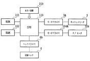
図7は、記録装置M1000における制御系のブロック構成図であり、CPU100は、後述する動作の制御処理やデータ処理等を実行する。ROM101は、それらの処理手順等のプログラムが格納され、またRAM102は、それらの処理を実行するためのワークエリアなどとして用いられる。記録ヘッド6からのインクの吐出は、CPU100が電気熱変換体などの駆動データ(画像データ)および駆動制御信号(ヒートパルス信号)をヘッドドライバ6Aに供給することにより行われる。CPU100は、キャリッジ1を主走査方向に駆動するためのキャリッジモータ3をモータドライバ3Aを介して制御し、また記録用紙5を副走査方向に搬送するためのP.Fモータ104をモータドライバ104Aを介して制御する。
FIG. 7 is a block diagram of a control system in the recording apparatus M1000, and the
図4は、インクタンクT2000の外観斜視図、図5は、そのインクタンクT2000の内部構成を説明するための斜視図、図6は、そのインクタンクT2000の分解斜視図である。 4 is an external perspective view of the ink tank T2000, FIG. 5 is a perspective view for explaining the internal configuration of the ink tank T2000, and FIG. 6 is an exploded perspective view of the ink tank T2000.
インクタンクT2000は、液体のインクを収納するための液体収納容器であり、図4に示すように、容器本体T2017と蓋部材T2018とを含み、それらの内側にインクの収納室が形成されている。インクタンクT2000の底面には、記録ヘッド6にインクを供給するためのインク供給口T2002が形成されている。さらにインクタンクT2000は、図6に示すように、ばね部材T2005、板部材T2022、可撓性フィルムT2004、メニスカス形成部材T2020、押え板T2021、および攪拌部材T2015を含む。
The ink tank T2000 is a liquid storage container for storing liquid ink. As shown in FIG. 4, the ink tank T2000 includes a container main body T2017 and a lid member T2018, and an ink storage chamber is formed inside them. . An ink supply port T2002 for supplying ink to the
容器本体T2017は、例えば、ポリプロピレンによって形成されており、図6に示すように、その容器本体T2017の底部のインク供給口T2002には、メニスカス形成部材T2020が備えられている。そのメニスカス形成部材T2020の外側には、押え部材T2021が取り付けられている。メニスカス形成部材T2020は、例えば、ポリプロピレンの繊維材料から形成されて毛細管力を有する毛管部材、あるいは、その毛管部材とフィルター部材とを組み合わせたものである。そのフィルター部材は、透過寸法が15〜30μm程度であり、その材質は、例えば、ステンレス材料やプリプロピレン等である。メニスカス形成部材T2020と容器本体T2017の内部はインク流路T2019によって連通されており、後述のインク収納室に外部から気泡が侵入しないように、インクのメニスカスを形成する。 The container main body T2017 is made of, for example, polypropylene. As shown in FIG. 6, the ink supply port T2002 at the bottom of the container main body T2017 includes a meniscus forming member T2020. A pressing member T2021 is attached to the outside of the meniscus forming member T2020. The meniscus forming member T2020 is, for example, a capillary member formed from a polypropylene fiber material and having a capillary force, or a combination of the capillary member and a filter member. The filter member has a transmission dimension of about 15 to 30 μm, and the material thereof is, for example, a stainless material or propylene. The meniscus forming member T2020 and the inside of the container main body T2017 are communicated with each other by an ink flow path T2019, and an ink meniscus is formed so that bubbles do not enter the ink storage chamber described later.
容器本体T2017の開口周縁部T2016には、可撓性フィルムT2004の周縁部が溶着され、これにより、容器本体T2017の内壁と可撓性フィルムT2004との間に、インクを収納するためのインク収納室が形成される。可撓性フィルムT2004は、例えば、ポリプロピレンの薄膜を含むフィルム部材(厚み20〜100μm程度)である。可撓性フィルムT2004は、ばね部材T2005により板部材T2022を介して外方に付勢され、これにより、インク収納室内に負圧が発生する。ばね部材T2005と板部材T2022は、例えば、ステンレス材料により形成されている。容器本体T2017の開口部には蓋部材T2018が取り付けられ、これにより、外方に凸型となる可撓性フィルムT2004が保護される。蓋部材T2018には大気連通部(不図示)が設けられ、これにより、可撓性フィルムT2004によってインク収納室と隔てられた蓋部材T2018の内側が大気圧とされている。 The peripheral edge portion of the flexible film T2004 is welded to the opening peripheral edge portion T2016 of the container main body T2017, and thereby ink storage for storing ink between the inner wall of the container main body T2017 and the flexible film T2004. A chamber is formed. The flexible film T2004 is, for example, a film member (thickness of about 20 to 100 μm) including a polypropylene thin film. The flexible film T2004 is biased outward by the spring member T2005 via the plate member T2022, thereby generating a negative pressure in the ink storage chamber. The spring member T2005 and the plate member T2022 are made of, for example, a stainless material. A lid member T2018 is attached to the opening of the container body T2017, thereby protecting the flexible film T2004 that is convex outward. The lid member T2018 is provided with an atmospheric communication portion (not shown), and thereby the inside of the lid member T2018 separated from the ink storage chamber by the flexible film T2004 is set to atmospheric pressure.
インク収納室内のインクがインク供給口T2002を通して記録ヘッド6へ供給されて、そのインクが消費されるにつれて、ばね部材T2005が縮み、および可撓性フィルムT2004の撓みを伴って、インク収納室T2001の容積が減少する。板部材T2022には、後述する支持部材T2023との干渉を避けるための開口T2027が設けられている。そのため、板部材T2022が容器本体T2017の内壁に接するまで、インク収納室内のインクを消費することが可能である。
As the ink in the ink storage chamber is supplied to the
攪拌部材T2015には、支持部材T2023によって支持される被支持端と、揺動自在な移動端と、が形成されており、キャリッジ1が移動する矢印Xの主走査方向に揺動することが可能である。攪拌部材T2015は、インクの比重よりも重い材料(例えばSUS)によって構成されており、後述する記録動作時および撹拌動作時に、キャリッジ1の往復移動によって生じる慣性力により揺動して、インク収納室内のインクを攪拌する。支持部材T2023の先端には抜け止め部T2024が設けられており、攪拌部材T2015の脱落が防止される。 The stirring member T2015 is formed with a supported end supported by the support member T2023 and a swingable moving end, and can swing in the main scanning direction of the arrow X in which the carriage 1 moves. It is. The agitation member T2015 is made of a material heavier than the specific gravity of ink (for example, SUS), and oscillates by an inertial force generated by the reciprocating movement of the carriage 1 during a recording operation and an agitation operation described later, thereby Stir the ink. A stopper T2024 is provided at the tip of the support member T2023 to prevent the stirring member T2015 from falling off.
図1は、インクタンクT2000内のインクの攪拌するために、インクジェット記録装置M1000によって実行される動作を説明するためのフローチャートである。 FIG. 1 is a flowchart for explaining an operation executed by the ink jet recording apparatus M1000 for stirring the ink in the ink tank T2000.
インクジェット記録装置M1000には、パーソナルコンピュータ(PC)等の外部装置(ホスト装置)から、記録信号が入力される(ステップS1)。その記録信号が入力されたときに、前回のキャリッジ1の往復移動の終了時点からの経過時間T、つまりインクタンクT2000内のインクが攪拌されてからの経過時間Tを読み込む(ステップS2)。インクの撹拌は、後述する記録動作または撹拌動作によって行なわれる。記録装置M1000あるいは記録ヘッドには、このような経過時間Tを計測するためのタイマーが備わっている。 A recording signal is input to the ink jet recording apparatus M1000 from an external apparatus (host apparatus) such as a personal computer (PC) (step S1). When the recording signal is input, the elapsed time T from the end of the previous reciprocating movement of the carriage 1, that is, the elapsed time T after the ink in the ink tank T2000 is stirred is read (step S2). Ink agitation is performed by a recording operation or an agitation operation described later. The recording apparatus M1000 or the recording head is provided with a timer for measuring such elapsed time T.
経過時間Tが規定時間T1よりも短い場合には、入力された記録信号に基づいて記録動作を行う(ステップS3)。この記録動作においては、入力した記録信号に基づき、キャリッジの往復移動を伴って記録用紙5上に画像を記録し、その際に、撹拌部材T2015が揺動してインク収納室内のインクを攪拌する。このような記録動作は、ホスト装置から順次入力される記録信号に基づいて繰り返し実行する(ステップS3,4)。そして、このような一連の記録動作が終了すると次のステップS5に移行し、その記録動作時における記録量として、キャリッジの往復移動の回数つまりスキャン回数を読み込む。そのスキャン回数は、ステップS4の記録動作時に順次カウントして、記録ヘッドに備わる記憶素子に記憶させておいて、その記憶内容を記録装置が読み込むようにしてもよい。
If the elapsed time T is shorter than the specified time T1, a recording operation is performed based on the input recording signal (step S3). In this recording operation, based on the input recording signal, an image is recorded on the
ステップS5においては、記録動作時における記録量としてのスキャン回数に応じて、インクタンク内のインクを攪拌するためのキャリッジ移動の条件(ここでは、キャリッジの移動回数)を設定する。すなわち、スキャン回数が多い場合、つまり記録動作(ステップS3)時における記録量が多かった場合には、その記録動作時におけるインクの撹拌程度が比較的高いため、撹拌動作(ステップS6)時におけるキャリッジの往復移動の回数を比較的少なめに設定する。例えば、攪拌のための往復移動回数を20回に設定する。なお、記録量が十分に多かった場合には攪拌不要であるため、攪拌のための往復移動回数を0回に設定する。一方、スキャン回数が少ない場合、つまり記録動作(ステップS3)時における記録量が少なかった場合には、その記録動作時におけるインクの撹拌程度が比較的低いため、撹拌動作(ステップS6)時におけるキャリッジの往復移動の回数を比較的多めに設定する。例えば、攪拌のための往復移動回数を50回に設定する。 その後、その往復移動回数だけキャリッジを往復移動させることにより、撹拌部材T2015によってインク収納室内のインクを攪拌する(ステップS6)。このときには画像の記録動作を伴わないため、このステップS6におけるキャリッジの往復移動を撹拌動作ともいう。 In step S5, a carriage movement condition (here, the number of carriage movements) for stirring the ink in the ink tank is set in accordance with the number of scans as the recording amount during the recording operation. That is, when the number of scans is large, that is, when the amount of recording during the recording operation (step S3) is large, the degree of ink agitation during the recording operation is relatively high, and thus the carriage during the agitation operation (step S6). Set the number of reciprocating movements to a relatively small number. For example, the number of reciprocating movements for stirring is set to 20 times. It should be noted that when the recording amount is sufficiently large, stirring is not required, so the number of reciprocating movements for stirring is set to zero. On the other hand, when the number of scans is small, that is, when the recording amount during the recording operation (step S3) is small, the degree of ink agitation during the recording operation is relatively low, and thus the carriage during the agitation operation (step S6). Set a relatively large number of reciprocal movements. For example, the number of reciprocating movements for stirring is set to 50 times. After that, the carriage is reciprocated by the number of reciprocations, thereby agitating the ink in the ink storage chamber by the agitating member T2015 (step S6). At this time, since no image recording operation is involved, the reciprocating movement of the carriage in step S6 is also referred to as a stirring operation.
このように、記録動作(ステップS3)時におけるインクの撹拌の程度に応じて、撹拌動作(ステップS6)のためのキャリッジの往復移動の回数を設定する。これにより、撹拌部材T2015を利用してインク収納室内のインクを充分に攪拌することができる。なお、前述した通り、スキャン回数が多くて、記録動作(ステップS3)時にインクが充分に攪拌された場合には、撹拌動作(ステップS6)を行わなくてもよい。 In this manner, the number of carriage reciprocations for the stirring operation (step S6) is set according to the degree of ink stirring during the recording operation (step S3). Accordingly, the ink in the ink storage chamber can be sufficiently stirred using the stirring member T2015. As described above, when the number of scans is large and the ink is sufficiently stirred during the recording operation (step S3), the stirring operation (step S6) may not be performed.
撹拌動作(ステップS6)の終了後は、経過時間Tを計測するためのタイマーをリセットする(ステップS7)。そのタイマーは、この時点から経過時間Tの計測をスタートすることになる。その後、記録ヘッド6のノズルからのインク蒸発、およびノズル内におけるインクの固着を防止するために、そのノズルをインクジェット記録装置M1000のキャッピング装置8により被覆する(ステップS8)。
After completion of the stirring operation (step S6), a timer for measuring the elapsed time T is reset (step S7). The timer starts measuring the elapsed time T from this point. Thereafter, in order to prevent ink evaporation from the nozzles of the
一方、ステップ2において経過時間Tが所定の規定時間T1より長い場合には、記録動作に先立ち、ステップS9において、キャリッジを所定回数だけ往復移動させてインクタンク内のインクを攪拌する(撹拌動作)。その後、ノズルのクリーニング動作を行なう(ステップS10)。そのクリーニング動作においては、前述したように、記録ヘッドのノズル部を被覆したキャップ内に負圧を導入することにより、画像の記録に寄与しないインクをノズルから吸引排出(吸引回復動作)する。この吸引回復動作により、インク流路およびインクタンク内のインクが所定量排出されることになる。
On the other hand, if the elapsed time T is longer than the predetermined specified time T1 in
その後、前述したステップS3,4と同様に記録動作(ステップS11,12)を行ってから、前述したステップS7,8と同様に、タイマーのリセット(ステップS13)とキャッピング(ステップS14)を行なう。 Thereafter, the recording operation (steps S11 and S12) is performed in the same manner as in steps S3 and S4 described above, and then the timer is reset (step S13) and capping (step S14) is performed in the same manner as in steps S7 and S8 described above.
なお、前回のキャリッジ移動終了からの経過時間Tが短い場合、インクタンク内の顔料成分の沈降の程度は比較的小さいため、記録結果に与える影響は少ない。したがって、経過時間Tが規定時間T1よりも小さい場合には、ステップS3のように、撹拌動作を行なうことなく記録動作を行っても問題はない。特に、記録動作時の記録動作量が多い場合はインクタンク内のインクが充分に撹拌されるため、撹拌動作を行なわなくても顔料成分の沈降の進行を抑制することができる。一方、経過時間Tが短く記録動作量が少ない場合には、記録動作(ステップS3)後に撹拌動作(ステップS6)を行なうため、記録信号が入力されてから記録を終了するまでの間に、撹拌動作に要する時間は含まれない。したがって、記録速度を犠牲にすることなく、インクタンク内におけるインクの顔料成分の沈降を防止することができる。 Note that when the elapsed time T from the end of the previous carriage movement is short, the degree of sedimentation of the pigment component in the ink tank is relatively small, and therefore the influence on the recording result is small. Therefore, when the elapsed time T is smaller than the specified time T1, there is no problem even if the recording operation is performed without performing the stirring operation as in step S3. In particular, when the amount of recording operation during the recording operation is large, the ink in the ink tank is sufficiently agitated, so that the progress of sedimentation of the pigment component can be suppressed without performing the agitation operation. On the other hand, when the elapsed time T is short and the recording operation amount is small, the agitation operation (step S6) is performed after the recording operation (step S3), so that the agitation is performed after the recording signal is input until the recording is finished. The time required for operation is not included. Therefore, it is possible to prevent sedimentation of the pigment component of the ink in the ink tank without sacrificing the recording speed.
また、記録量に対応する情報として、キャリッジのスキャン回数(移動回数)に代えて、ドットカウント値を用いてもよい。すなわち、インクジェット記録装置においては、入力された記録信号に基づいて記録ヘッドからインク滴を吐出して画像を記録するため、インク滴の吐出数、つまりインク滴によって形成されるドット数が記録量に対応する。したがって、記録信号(記録データ)に基づいて、インク滴の吐出数をドットカウント値としてカウントし、それを記録量に対応する情報として用いることができる。つまり、そのドットカウント値に応じて、ステップS6の攪拌動作時におけるキャリッジの往復移動の回数を設定することができる。 Further, as information corresponding to the recording amount, a dot count value may be used instead of the carriage scan count (movement count). In other words, in an ink jet recording apparatus, an image is recorded by ejecting ink droplets from a recording head based on an input recording signal, so the number of ink droplets ejected, that is, the number of dots formed by ink droplets, is the recording amount. Correspond. Therefore, based on the recording signal (recording data), the number of ink droplet ejections can be counted as a dot count value and used as information corresponding to the recording amount. That is, the number of reciprocating movements of the carriage during the stirring operation in step S6 can be set according to the dot count value.
(第2の実施形態)
図8は、本発明の第2の実施形態を説明するためのフローチャート図である。本実施形態においては、記録量を判断するステップS5Aが前述した図1の実施形態のステップS5と異なっており、同じステップについては同一の符号を付して説明を省略する。
(Second Embodiment)
FIG. 8 is a flowchart for explaining the second embodiment of the present invention. In this embodiment, step S5A for determining the recording amount is different from step S5 of the embodiment of FIG. 1 described above, and the same steps are denoted by the same reference numerals and description thereof is omitted.
インクタンク内に設けた攪拌部材T2015は、キャリッジの往復移動により生じる慣性力によって、インクタンク内を移動してインクを攪拌する。そのため、その攪拌部材T2015に作用する慣性力が大きい程、攪拌部材T2015の移動範囲が大きくなると共に移動速度も速くなる。撹拌部材T2015の移動範囲が大きく、移動速度が速くなる程、インクの攪拌効率が上がるため、キャリッジの移動速度が速い場合には、記録動作時におけるキャリッジの移動回数が少なくてもインクの攪拌の程度を高めることができる。このようにキャリッジの移動条件に応じて、インクの攪拌効率は変化する。 The stirring member T2015 provided in the ink tank moves in the ink tank and stirs the ink by the inertial force generated by the reciprocating movement of the carriage. Therefore, the greater the inertial force acting on the stirring member T2015, the larger the moving range of the stirring member T2015 and the faster the moving speed. As the moving range of the stirring member T2015 is larger and the moving speed is faster, the ink stirring efficiency increases. Therefore, when the carriage moving speed is high, the ink stirring speed can be reduced even if the number of times of carriage movement is small. The degree can be increased. As described above, the ink stirring efficiency changes according to the carriage moving condition.
そこで本実施形態においては、ステップS5Aにて、記録信号に対応する記録量と、インクジェット記録装置を制御するドライバ(プログラム)上に設定された記録モードと、を読み込む。そして、それらの情報に基づいて、ステップS6の攪拌動作におけるキャリッジの往復移動の回数を設定する。 Therefore, in the present embodiment, in step S5A, the recording amount corresponding to the recording signal and the recording mode set on the driver (program) that controls the ink jet recording apparatus are read. Then, based on the information, the number of times the carriage is reciprocated in the stirring operation in step S6 is set.
記録モードとしては、例えば、キャリッジが高速移動する高速記録モード、キャリッジが通常の速度で移動する通常記録モード、およびキャリッジが定速移動する高品位記録モードが選択的に設定される。高速記録モード、通常記録モード、および高品位記録モードにおけるキャリッジの移動速度Va、Vb、Vcは、Va>Vb>Vcの関係にある。高速記録モードによる記録動作(ステップS3)後に必要な攪拌動作量、つまり攪拌動作(ステップS6)におけるキャリッジの往復移動の回数はN(a)とする。同様に、通常記録モードによる記録動作(ステップS3)後に必要な攪拌動作量をN(b)、高品位記録モードによる記録動作(ステップS3)後に必要な攪拌動作量をN(c)とする。それぞれの攪拌動作量は、N(c)>N(b)>N(a)の関係となるように設定する。 As the recording mode, for example, a high-speed recording mode in which the carriage moves at a high speed, a normal recording mode in which the carriage moves at a normal speed, and a high-quality recording mode in which the carriage moves at a constant speed are selectively set. The carriage moving speeds Va, Vb, and Vc in the high-speed recording mode, the normal recording mode, and the high-quality recording mode have a relationship of Va> Vb> Vc. The amount of stirring operation required after the recording operation (step S3) in the high-speed recording mode, that is, the number of times the carriage reciprocates in the stirring operation (step S6) is N (a). Similarly, the amount of stirring operation required after the recording operation in the normal recording mode (step S3) is N (b), and the amount of stirring operation required after the recording operation in the high-quality recording mode (step S3) is N (c). The respective stirring operation amounts are set so as to satisfy the relationship of N (c)> N (b)> N (a).
このように、記録動作時におけるキャリッジの移動速度(キャリッジの移動条件)に応じて攪拌動作量を設定することにより、効率よく攪拌動作(ステップS6)を行なうことができる。つまり、インクの攪拌に要するキャリッジの往復移動回数を少なく設定して、充分な攪拌効果を得ることができる。 As described above, the agitation operation (step S6) can be efficiently performed by setting the agitation operation amount according to the carriage movement speed (carriage movement condition) during the recording operation. That is, it is possible to obtain a sufficient stirring effect by setting the number of times of reciprocation of the carriage required for stirring the ink.
(他の実施形態)
上記第1、第2の本実施形態では、攪拌動作のためのキャリッジ移動の条件として、キャリッジ移動回数を設定する構成について説明したが、本発明で設定可能な条件はこれに限られるものではない。インクが攪拌される程度は、キャリッジの移動距離や移動速度、加速度・移動時間によっても異なる。そこで、攪拌動作のためのキャリッジ移動の条件として、キャリッジの移動距離・キャリッジの移動速度・キャリッジの加速度・キャリッジの移動時間を設定する構成であってもよい。
(Other embodiments)
In the first and second embodiments, the configuration in which the number of carriage movements is set as the carriage movement condition for the stirring operation has been described. However, the conditions that can be set in the present invention are not limited to this. . The degree to which the ink is agitated also depends on the moving distance, moving speed, acceleration, and moving time of the carriage. Thus, the carriage movement conditions for the stirring operation may be set such that the carriage movement distance, carriage movement speed, carriage acceleration, and carriage movement time are set.
また、記録動作における画像の記録量を検知する方法としては、その記録動作時におけるキャリッジ移動の回数を検知する方法の他、記録データに基づくドットかウンド数を検知する方法であってもよい。また、画像の記録に用いる記録媒体の種類に応じてキャリッジの移動条件が異なる場合には、記録モードやキャリッジの往復移動速度の他、その記録媒体の種類に基づいて、インクを攪拌するためのキャリッジの往復移動回数を設定してもよい。 Further, as a method for detecting the image recording amount in the recording operation, there may be a method for detecting the number of dots or sounds based on the recording data in addition to a method for detecting the number of carriage movements during the recording operation. In addition, when the carriage moving condition varies depending on the type of the recording medium used for image recording, the ink is stirred based on the type of the recording medium in addition to the recording mode and the reciprocating speed of the carriage. The number of carriage reciprocations may be set.
T2000 インクタンク
T2015 攪拌部材
M1000 記録装置
1 キャリッジ
5 記録用紙(記録媒体)
6 記録ヘッド
8 キャッピング装置
100 CPU
101 ROM
102 RAM
T2000 Ink tank T2015 Stirring member M1000 Recording device 1
6
101 ROM
102 RAM
Claims (6)
前記キャリッジの前回の移動終了からの経過時間が所定時間以上の場合は、前記キャリッジを所定回数往復移動させて前記インクタンク内のインクを撹拌する撹拌動作を行った後に前記記録ヘッドに記録動作を行わせ、前記経過時間が前記所定時間未満の場合は、撹拌動作を行うことなく前記記録ヘッドに記録動作を行わせる制御手段と、
を備えるインクジェット記録装置において、
前記制御手段は、前記経過時間が前記所定時間未満の場合に、前記記録動作における記録量に応じて前記記録動作の後に撹拌動作を行うか否かを決定することを特徴とするインクジェット記録装置。 A recording head for recording by ejecting ink, an ink tank and a possible mounting carriage for containing ink to be supplied to said recording head,
When the elapsed time from the end of the previous movement of the carriage is equal to or longer than a predetermined time, a recording operation is performed on the recording head after performing a stirring operation of stirring the ink in the ink tank by reciprocating the carriage a predetermined number of times. Control means for causing the recording head to perform a recording operation without performing an agitation operation when the elapsed time is less than the predetermined time; and
In an inkjet recording apparatus comprising:
The control unit determines whether or not to perform a stirring operation after the recording operation according to a recording amount in the recording operation when the elapsed time is less than the predetermined time .
前記キャリッジの前回の移動終了からの経過時間が所定時間以上の場合は、前記キャリッジを所定回数往復移動させて前記インクタンク内のインクを撹拌する撹拌動作を行った後に前記記録ヘッドに記録動作を行わせ、前記経過時間が前記所定時間未満の場合は、撹拌動作を行うことなく前記記録ヘッドに記録動作を行わせる制御手段と、
を備えるインクジェット記録装置において、
前記制御手段は、前記経過時間が前記所定時間未満の場合に、前記記録動作の後に前記記録動作における記録モードに応じた回数前記キャリッジを往復移動させて撹拌動作を行うことを特徴とするインクジェット記録装置。 A carriage capable of mounting a recording head that performs recording by discharging ink, and an ink tank that stores ink supplied to the recording head;
When the elapsed time from the end of the previous movement of the carriage is equal to or longer than a predetermined time, a recording operation is performed on the recording head after performing a stirring operation of stirring the ink in the ink tank by reciprocating the carriage a predetermined number of times. Control means for causing the recording head to perform a recording operation without performing an agitation operation when the elapsed time is less than the predetermined time; and
In an inkjet recording apparatus comprising:
The control means performs an agitating operation by reciprocating the carriage a number of times according to a recording mode in the recording operation after the recording operation when the elapsed time is less than the predetermined time. apparatus.
Priority Applications (2)
| Application Number | Priority Date | Filing Date | Title |
|---|---|---|---|
| JP2006130794A JP5037855B2 (en) | 2006-05-09 | 2006-05-09 | Inkjet recording device |
| US11/743,703 US7914101B2 (en) | 2006-05-09 | 2007-05-03 | Ink jet printing apparatus with ink stirring by carriage reciprocation |
Applications Claiming Priority (1)
| Application Number | Priority Date | Filing Date | Title |
|---|---|---|---|
| JP2006130794A JP5037855B2 (en) | 2006-05-09 | 2006-05-09 | Inkjet recording device |
Publications (3)
| Publication Number | Publication Date |
|---|---|
| JP2007301772A JP2007301772A (en) | 2007-11-22 |
| JP2007301772A5 JP2007301772A5 (en) | 2011-03-24 |
| JP5037855B2 true JP5037855B2 (en) | 2012-10-03 |
Family
ID=38684688
Family Applications (1)
| Application Number | Title | Priority Date | Filing Date |
|---|---|---|---|
| JP2006130794A Active JP5037855B2 (en) | 2006-05-09 | 2006-05-09 | Inkjet recording device |
Country Status (2)
| Country | Link |
|---|---|
| US (1) | US7914101B2 (en) |
| JP (1) | JP5037855B2 (en) |
Families Citing this family (21)
| Publication number | Priority date | Publication date | Assignee | Title |
|---|---|---|---|---|
| JP4886586B2 (en) * | 2006-05-09 | 2012-02-29 | キヤノン株式会社 | Liquid storage container, head cartridge, inkjet recording apparatus, and liquid storage container stirring method |
| JP4926538B2 (en) * | 2006-05-11 | 2012-05-09 | キヤノン株式会社 | Liquid storage container and recording apparatus |
| JP4164519B2 (en) * | 2006-06-16 | 2008-10-15 | キヤノン株式会社 | Inkjet recording device |
| US8172380B2 (en) * | 2007-10-01 | 2012-05-08 | Brother Kogyo Kabushiki Kaisha | Dual chamber, liquid apparatus having liquid permeability |
| JP5268623B2 (en) * | 2008-12-24 | 2013-08-21 | キヤノン株式会社 | Ink jet recording apparatus and recording head recovery method thereof |
| EP3855297A3 (en) | 2009-09-22 | 2021-10-27 | Apple Inc. | Device method and graphical user interface for manipulating user interface objects |
| US9310907B2 (en) | 2009-09-25 | 2016-04-12 | Apple Inc. | Device, method, and graphical user interface for manipulating user interface objects |
| US8832585B2 (en) | 2009-09-25 | 2014-09-09 | Apple Inc. | Device, method, and graphical user interface for manipulating workspace views |
| JP5760309B2 (en) * | 2009-10-30 | 2015-08-05 | セイコーエプソン株式会社 | Liquid ejector |
| US8985836B2 (en) | 2010-05-12 | 2015-03-24 | Seiko Epson Corporation | Liquid stirring device |
| JP5660283B2 (en) * | 2010-05-12 | 2015-01-28 | セイコーエプソン株式会社 | Liquid supply device and droplet discharge device |
| JP5773584B2 (en) * | 2010-06-18 | 2015-09-02 | キヤノン株式会社 | Printing apparatus and ink supply method thereof |
| US9081494B2 (en) | 2010-07-30 | 2015-07-14 | Apple Inc. | Device, method, and graphical user interface for copying formatting attributes |
| US9098182B2 (en) | 2010-07-30 | 2015-08-04 | Apple Inc. | Device, method, and graphical user interface for copying user interface objects between content regions |
| JP5644248B2 (en) * | 2010-08-11 | 2014-12-24 | セイコーエプソン株式会社 | Droplet discharge device |
| JP5664023B2 (en) * | 2010-08-27 | 2015-02-04 | セイコーエプソン株式会社 | Image forming apparatus |
| JP2012076422A (en) | 2010-10-05 | 2012-04-19 | Canon Inc | Printing apparatus and pigment ink stirring method |
| JP5197872B2 (en) * | 2012-07-09 | 2013-05-15 | キヤノン株式会社 | Inkjet recording device |
| US11077689B2 (en) * | 2015-12-07 | 2021-08-03 | The Procter & Gamble Company | Systems and methods for providing a service station routine |
| US11590782B2 (en) | 2015-12-07 | 2023-02-28 | The Procter & Gamble Company | Systems and methods for providing a service station routine |
| JP7164448B2 (en) * | 2019-01-23 | 2022-11-01 | 株式会社ミマキエンジニアリング | Inkjet printer and method of controlling an inkjet printer |
Family Cites Families (11)
| Publication number | Priority date | Publication date | Assignee | Title |
|---|---|---|---|---|
| JP3335050B2 (en) * | 1995-10-09 | 2002-10-15 | キヤノン株式会社 | Ink jet recording device |
| US5988782A (en) * | 1995-04-07 | 1999-11-23 | Canon Kabushiki Kaisha | Ink-jet printing apparatus |
| JP3190540B2 (en) * | 1995-04-07 | 2001-07-23 | キヤノン株式会社 | Inkjet printing equipment |
| JP3431051B2 (en) * | 1996-05-20 | 2003-07-28 | セイコーエプソン株式会社 | Ink jet recording apparatus and ink cartridge |
| KR100186618B1 (en) * | 1996-09-16 | 1999-05-15 | 삼성전자주식회사 | Density uniforming method of pigment ink |
| JP4464059B2 (en) * | 2002-03-25 | 2010-05-19 | キヤノン株式会社 | Inkjet recording device |
| JP2003311933A (en) * | 2002-04-24 | 2003-11-06 | Dainippon Screen Mfg Co Ltd | Patch measuring device and printing device incorporating the same |
| JP2004167701A (en) * | 2002-11-15 | 2004-06-17 | Seiko Epson Corp | Liquid ejector |
| JP2004216761A (en) | 2003-01-16 | 2004-08-05 | Seiko Epson Corp | Ink tank and inkjet printer |
| JP2005066520A (en) | 2003-08-26 | 2005-03-17 | Seiko Epson Corp | Liquid housing body, liquid tank, liquid stirrer and liquid injector |
| JP2006044153A (en) * | 2004-08-06 | 2006-02-16 | Seiko Epson Corp | Liquid storing body and liquid injection device |
-
2006
- 2006-05-09 JP JP2006130794A patent/JP5037855B2/en active Active
-
2007
- 2007-05-03 US US11/743,703 patent/US7914101B2/en active Active
Also Published As
| Publication number | Publication date |
|---|---|
| JP2007301772A (en) | 2007-11-22 |
| US7914101B2 (en) | 2011-03-29 |
| US20070263025A1 (en) | 2007-11-15 |
Similar Documents
| Publication | Publication Date | Title |
|---|---|---|
| JP5037855B2 (en) | Inkjet recording device | |
| JP4235633B2 (en) | Ink tank and recording device | |
| JP4926538B2 (en) | Liquid storage container and recording apparatus | |
| JP5272363B2 (en) | Fluid ejection device | |
| JP4646745B2 (en) | Ink tank | |
| JP4444934B2 (en) | Liquid storage container | |
| JP4273819B2 (en) | Liquid ejecting apparatus and control method thereof | |
| JP5223277B2 (en) | Flushing method for fluid ejection device | |
| JP2002273912A (en) | Ink jet recording device | |
| JP4916190B2 (en) | Ink tank and printer | |
| JP5343673B2 (en) | Recording apparatus and method for controlling fine vibration in recording apparatus | |
| JP3842568B2 (en) | Liquid ejector | |
| JP3319733B2 (en) | INK JET RECORDING APPARATUS AND CONTROL METHOD THEREOF | |
| JP2007160716A (en) | Liquid ejector | |
| US7621627B2 (en) | Liquid container | |
| JP5441397B2 (en) | Recording method in recording apparatus | |
| JP2010137516A (en) | Recording head control device, recording device, and recording head control method | |
| JP2010105310A (en) | Liquid jet device | |
| JP2008074113A (en) | Liquid jetting apparatus, and driving method for apparatus | |
| JP5282585B2 (en) | Image forming apparatus | |
| JP6142615B2 (en) | Printing device | |
| JP2002264353A (en) | Ink jet recorder | |
| JP2004034471A (en) | Liquid ejector | |
| US20230339232A1 (en) | Liquid storage container, liquid consumption apparatus, and recording apparatus | |
| JP2011121243A (en) | Ink tank and liquid ejection device |
Legal Events
| Date | Code | Title | Description |
|---|---|---|---|
| A621 | Written request for application examination |
Free format text: JAPANESE INTERMEDIATE CODE: A621 Effective date: 20090511 |
|
| RD02 | Notification of acceptance of power of attorney |
Free format text: JAPANESE INTERMEDIATE CODE: A7422 Effective date: 20101106 |
|
| A521 | Request for written amendment filed |
Free format text: JAPANESE INTERMEDIATE CODE: A523 Effective date: 20110207 |
|
| A977 | Report on retrieval |
Free format text: JAPANESE INTERMEDIATE CODE: A971007 Effective date: 20110628 |
|
| A131 | Notification of reasons for refusal |
Free format text: JAPANESE INTERMEDIATE CODE: A131 Effective date: 20110708 |
|
| A521 | Request for written amendment filed |
Free format text: JAPANESE INTERMEDIATE CODE: A523 Effective date: 20110906 |
|
| TRDD | Decision of grant or rejection written | ||
| A01 | Written decision to grant a patent or to grant a registration (utility model) |
Free format text: JAPANESE INTERMEDIATE CODE: A01 Effective date: 20120703 |
|
| A01 | Written decision to grant a patent or to grant a registration (utility model) |
Free format text: JAPANESE INTERMEDIATE CODE: A01 |
|
| A61 | First payment of annual fees (during grant procedure) |
Free format text: JAPANESE INTERMEDIATE CODE: A61 Effective date: 20120705 |
|
| FPAY | Renewal fee payment (event date is renewal date of database) |
Free format text: PAYMENT UNTIL: 20150713 Year of fee payment: 3 |
|
| R151 | Written notification of patent or utility model registration |
Ref document number: 5037855 Country of ref document: JP Free format text: JAPANESE INTERMEDIATE CODE: R151 |
|
| FPAY | Renewal fee payment (event date is renewal date of database) |
Free format text: PAYMENT UNTIL: 20150713 Year of fee payment: 3 |