JP5037726B2 - Pressurized body and pellicle sticking device - Google Patents
Pressurized body and pellicle sticking device Download PDFInfo
- Publication number
- JP5037726B2 JP5037726B2 JP2011518116A JP2011518116A JP5037726B2 JP 5037726 B2 JP5037726 B2 JP 5037726B2 JP 2011518116 A JP2011518116 A JP 2011518116A JP 2011518116 A JP2011518116 A JP 2011518116A JP 5037726 B2 JP5037726 B2 JP 5037726B2
- Authority
- JP
- Japan
- Prior art keywords
- pellicle
- pressurizing
- pressure
- photomask
- mask
- Prior art date
- Legal status (The legal status is an assumption and is not a legal conclusion. Google has not performed a legal analysis and makes no representation as to the accuracy of the status listed.)
- Active
Links
Images
Classifications
-
- G—PHYSICS
- G03—PHOTOGRAPHY; CINEMATOGRAPHY; ANALOGOUS TECHNIQUES USING WAVES OTHER THAN OPTICAL WAVES; ELECTROGRAPHY; HOLOGRAPHY
- G03F—PHOTOMECHANICAL PRODUCTION OF TEXTURED OR PATTERNED SURFACES, e.g. FOR PRINTING, FOR PROCESSING OF SEMICONDUCTOR DEVICES; MATERIALS THEREFOR; ORIGINALS THEREFOR; APPARATUS SPECIALLY ADAPTED THEREFOR
- G03F1/00—Originals for photomechanical production of textured or patterned surfaces, e.g., masks, photo-masks, reticles; Mask blanks or pellicles therefor; Containers specially adapted therefor; Preparation thereof
- G03F1/62—Pellicles, e.g. pellicle assemblies, e.g. having membrane on support frame; Preparation thereof
- G03F1/64—Pellicles, e.g. pellicle assemblies, e.g. having membrane on support frame; Preparation thereof characterised by the frames, e.g. structure or material, including bonding means therefor
-
- G—PHYSICS
- G03—PHOTOGRAPHY; CINEMATOGRAPHY; ANALOGOUS TECHNIQUES USING WAVES OTHER THAN OPTICAL WAVES; ELECTROGRAPHY; HOLOGRAPHY
- G03F—PHOTOMECHANICAL PRODUCTION OF TEXTURED OR PATTERNED SURFACES, e.g. FOR PRINTING, FOR PROCESSING OF SEMICONDUCTOR DEVICES; MATERIALS THEREFOR; ORIGINALS THEREFOR; APPARATUS SPECIALLY ADAPTED THEREFOR
- G03F1/00—Originals for photomechanical production of textured or patterned surfaces, e.g., masks, photo-masks, reticles; Mask blanks or pellicles therefor; Containers specially adapted therefor; Preparation thereof
- G03F1/68—Preparation processes not covered by groups G03F1/20 - G03F1/50
Landscapes
- Physics & Mathematics (AREA)
- General Physics & Mathematics (AREA)
- Preparing Plates And Mask In Photomechanical Process (AREA)
Description
本発明は、フォトマスクに、ペリクル膜及び支持フレームによって構成されるペリクル組立体を貼り付けるための貼付装置、及び、当該貼付装置においてフォトマスクとペリクル組立体とを加圧するための加圧体、に関する。 The present invention relates to an application device for attaching a pellicle assembly composed of a pellicle film and a support frame to a photomask, and a pressurizing body for applying pressure to the photomask and the pellicle assembly in the application device, About.
従来、フォトマスクにペリクル組立体を貼り付けるためのペリクル貼付装置が、知られている。ペリクル貼付装置の一例が、特許文献1に記載されている。
Conventionally, a pellicle sticking device for sticking a pellicle assembly to a photomask is known. An example of a pellicle sticking device is described in
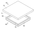
図13は、フォトマスク70とペリクル組立体80とを示す斜視図である。フォトマスク70は、半導体やフラットパネルディスプレイなどの電子部品の内部回路を、光学的な転写によって作成するための原板である。フォトマスク70の一方の面はクロム面(パターン面)71であり、クロム面71には回路パターンが描かれた露光パターン領域71aが形成されている。フォトマスク70の他方の面は、一般的には、ガラス面72と呼ばれている。
FIG. 13 is a perspective view showing the
ペリクル組立体80は、フレーム付きのペリクル膜を意味しており、ペリクル膜81とペリクルフレーム82とから構成されている。ペリクル膜81は、ペリクルフレーム82の下面に張られている。ペリクル組立体80は、ペリクル膜81をフォトマスク70に固定するために、使用される。フォトマスク70に固定されたペリクル組立体80は、クロム面71を塵挨から保護する。
The
ペリクル貼付装置は、フォトマスク70とペリクル組立体80とを挟み込み、両者を互いに押し付ける。ここで、ペリクルフレーム82の上面には、接着剤層90が設けられている。このため、フォトマスク70とペリクル組立体80とが加圧されることによって、フォトマスク70にペリクル組立体80が貼り付けられる。
The pellicle sticking apparatus sandwiches the
現在、主流の半導体用フォトマスクは、一辺が152mm(6インチ)の正方形であり、その厚みは、約6.3mmである。このフォトマスクは、一般的に、6インチマスク又は6025フォトマスクと呼ばれる。6インチのフォトマスクの場合、ペリクル膜がクロム面の露光パターン領域を覆うように、ペリクル組立体がクロム面に貼り付けられる。 Currently, the mainstream semiconductor photomask is a square with sides of 152 mm (6 inches), and its thickness is about 6.3 mm. This photomask is generally referred to as a 6 inch mask or 6025 photomask. In the case of a 6-inch photomask, the pellicle assembly is attached to the chrome surface so that the pellicle film covers the exposed pattern region of the chrome surface.
半導体の製造工程によっては、別の半導体用フォトマスクも用いられている。この半導体用フォトマスクは、一辺が126.6mm(5インチ)の正方形であり、その厚みは、約2.3mmである。5インチのフォトマスクの場合、ペリクル組立体がクロム面に貼り付けられる場合と、ペリクル組立体がクロム面及びガラス面の双方に貼り付けられる場合とがある。 Other semiconductor photomasks are also used depending on the semiconductor manufacturing process. This semiconductor photomask is a square having a side of 126.6 mm (5 inches) and a thickness of about 2.3 mm. In the case of a 5-inch photomask, the pellicle assembly may be attached to the chrome surface, and the pellicle assembly may be attached to both the chrome surface and the glass surface.
ペリクル貼付装置において、フォトマスクにペリクル組立体を貼り付けるときのフォトマスクの姿勢は、次の2通りの姿勢が、一般的である。第1の姿勢では、フォトマスクが水平に保持されており、クロム面が下方を向いている。第2の姿勢では、フォトマスクが鉛直に保持されており、クロム面が水平方向を向いている。当然ながら、フォトマスクに貼り付けるペリクル組立体の姿勢も、フォトマスクの姿勢に対応して設定されている。 In the pellicle sticking apparatus, the posture of the photomask when the pellicle assembly is stuck to the photomask is generally the following two postures. In the first posture, the photomask is held horizontally and the chrome surface faces downward. In the second posture, the photomask is held vertically, and the chrome surface faces the horizontal direction. Of course, the posture of the pellicle assembly to be attached to the photomask is also set corresponding to the posture of the photomask.
図14は、従来のペリクル貼付装置1の要部を示す正面図である。ペリクル貼付装置1は水平式である。ペリクル貼付装置1においてフォトマスク70は水平に保持される。ペリクル貼付装置1は、下から上に向けて、下側エアシリンダ2、下側ベース部材3、ペリクル加圧体4、マスク加圧体5、及び上側ベース部材6を備えている。ペリクル加圧体4とマスク加圧体5との間には、下側のペリクル組立体80と、上側のフォトマスク70と、が配置される。ここで、ペリクル組立体80は、ペリクル加圧体4の上に載っており、フォトマスク70は、フォトマスク70を支持するための枠状のステージ(図示せず)の上に載っている。
FIG. 14 is a front view showing a main part of a conventional
ペリクル貼付装置1において、下側エアシリンダ2の駆動によって、ペリクル加圧体4が上側に移動する。ペリクル加圧体4は、ペリクル組立体80を介してフォトマスク70を押し上げながら、上昇する。ペリクル加圧体4及びマスク加圧体5は一対の圧子を構成しており、これらの間に配置されているフォトマスク70とペリクル組立体80とが加圧される。この結果、接着剤層90によって、ペリクル組立体80がフォトマスク70に貼り付けられる。
In the
ペリクル貼付装置1は、ペリクル組立体80及びフォトマスク70のサイズの変更に対応できるように、構成されている。具体的には、ペリクル組立体80及びフォトマスク70の異なるサイズに対応して、異なるサイズのペリクル加圧体4及びマスク加圧体5が用意されている。また、ペリクル組立体80に応じてペリクル加圧体4を交換できるように、ペリクル加圧体4が下側ベース部材3に対して着脱自在である。フォトマスク70に応じてマスク加圧体5を交換できるように、マスク加圧体5が上側ベース部材6に対して着脱自在である。
The
ペリクル加圧体4及びマスク加圧体5は、金属(硬質アルミ)又はエンジニアリングプラスチックを機械加工することによって製造された成型品である。ペリクル加圧体4は、ペリクル組立体80のペリクルフレーム82のみに接触する突出部4aを有しており、ペリクルフレーム82のみを加圧する。マスク加圧体5は、フォトマスク70の外周部のみに接触する突出部5aを有しており、フォトマスク70の外周部のみを加圧する。ここで、外周部は、ガラス面72において、クロム面71上のパターン領域71aの外側を指している。なお、フォトマスク70の加圧においては、ガラス面72の外周部を加圧する場合だけでなく、ガラス面72の内部(ガラス面72においてペリクルフレーム82に対応する部分)を加圧する場合もある。
The
集積回路である半導体は、年々、微細化が進んでいる。このため、半導体の製造工程(露光工程)で使用される半導体用フォトマスクの露光パターンも、可能な限り微細化が進んでいる。ここで、半導体の製造工程(露光工程)では、フォトマスク70の露光パターン領域71aを通過した照射光が、レンズを介して、シリコンウエハ上に結像する。このため、露光パターンの微細化は、結像位置のズレにおける許容範囲が小さくなることを意味している。
Semiconductors, which are integrated circuits, are increasingly miniaturized year by year. For this reason, the exposure pattern of the semiconductor photomask used in the semiconductor manufacturing process (exposure process) is also miniaturized as much as possible. Here, in the semiconductor manufacturing process (exposure process), the irradiation light that has passed through the
接着剤層90によってペリクル組立体80がフォトマスク70に固定されると、フォトマスク70に微細な歪みが発生する。露光パターン領域71aにおける歪みは、露光工程における結像位置を変化させてしまう。
When the
このような歪みが発生する原因は、弾性を有する接着剤層90が、加圧処理において面方向に不均一な加圧荷重を受けること、である。以下で詳しく説明する。
The cause of such distortion is that the elastic
接着剤層90は、一般的に熱可塑性樹脂系接着剤をペリクルフレーム82の上面に塗布することによって、成形されている。つまり、接着剤層90は、常温では、可塑性を発揮せず、弾性を有している。このため、加圧処理において、加圧荷重を受けた接着剤層90は、塑性変形することなく、弾性変形する。
The
ペリクル貼付装置1において、フォトマスク70とペリクル膜81とができるだけ平行に近くなるように、機械加工精度及び組立精度が考慮されている。例えば、ペリクル加圧面P4の平坦度が5μm以下且つマスク加圧面P5の平坦度が5μm以下となるように、ペリクル加圧体4及びマスク加圧体5の機械加工精度が保たれている。また、ペリクル加圧面P4とマスク加圧面P5との平行度が10μm以下となるように、ペリクル貼付装置1を構成する各部品の組立精度が保たれている。ここで、ペリクル加圧面P4は、ペリクル加圧体4においてペリクルフレーム82に接触する面(突出部の上面)を指しており、マスク加圧面P5は、マスク加圧体5においてフォトマスク70に接触する面(突出部の下面)を指している。
In the
フォトマスク70及びペリクル組立体80は剛体であるので、加圧処理において変形することはない。また、ペリクル貼付装置1は、接着剤層90が発揮できる弾性力より大きな加圧荷重を加えることによって、接着剤層90を圧縮できる。このため、加圧面P4、P5間の平行度がそのまま、接着剤層90の両面(上面及び下面)間の平行度となる。平行度がゼロではないとき、接着剤層90の両面間の距離が不均一である。両面間の距離が近い部分は、両面間の距離が遠い部分よりも大きな加圧荷重を受けることによって、両面間の距離が遠い部分よりも大きく変形している。この結果、接着剤層90が加圧方向だけでなく、面方向にも変形する。加圧処理が終了すると、ペリクル貼付装置1からペリクル組立体80付きフォトマスク70が取り出される。加圧荷重の付与がなくなったとき、接着剤層90において、加圧方向の変形は解消されるが、面方向の変形は残留する。このため、接着剤層90が、フォトマスク70のクロム面71を引き延ばす又は押し縮めるように、面方向において弾性力を及ぼす。この結果、露光パターン領域71aに微細な歪みが発生する。
Since the
つまり、本発明の課題は、加圧処理において、接着剤層に加わる加圧荷重を面方向において均一にすること、である。面方向において均一な加圧荷重を接着剤層に加えることによって、接着剤層の変形量を面方向において均一にできる。接着剤層の変形量を面方向において均一にすることによって、接着剤層がフォトマスクの露光パターンに歪みを発生させることを防止できる。 That is, the subject of this invention is making the pressurization load added to an adhesive bond layer uniform in a surface direction in a pressurization process. By applying a uniform pressure load to the adhesive layer in the surface direction, the deformation amount of the adhesive layer can be made uniform in the surface direction. By making the deformation amount of the adhesive layer uniform in the surface direction, it is possible to prevent the adhesive layer from distorting the exposure pattern of the photomask.
加圧荷重を面方向において均一に近づけるために、一対の加圧面間の平行度について、加圧処理中の平行度(実際値)を、機械加工精度及び組立精度によって発生する平行度(初期値)よりも小さくすること、が必要である。そこで、本発明は、加圧荷重を受けたときに、一対の加圧面間の平行度を小さくするように作動する加圧体を、提供する。 In order to make the pressure load uniform in the surface direction, the parallelism between the pair of pressure surfaces (actual value) during the pressure treatment (actual value) is the parallelism generated by machining accuracy and assembly accuracy (initial value) ) Is necessary. Therefore, the present invention provides a pressure body that operates to reduce the parallelism between a pair of pressure surfaces when a pressure load is applied.
第1発明は、所定の加圧方向に沿って、フォトマスクと、ペリクル膜と前記ペリクル膜を支持するペリクルフレームとによって構成されているペリクル組立体とを、加圧するための加圧体において、前記加圧方向の一側において、前記フォトマスク又は前記ペリクル組立体に接触するための、3以上の接触部材と、前記接触部材を前記一側に脱落不能に支持し、且つ、前記接触部材を支持する位置を前記加圧方向に直交する平面内で変更可能とする、開口部が形成された、本体と、前記加圧方向の他側において、前記本体に固定される、カバー体と、前記加圧方向において、前記接触部材と前記カバー体との間に配置される、緩衝材部材と、を備えている。 A first invention is a pressurizing body for pressurizing a pellicle assembly constituted by a photomask, a pellicle film, and a pellicle frame that supports the pellicle film along a predetermined pressurizing direction. Three or more contact members for contacting the photomask or the pellicle assembly on one side in the pressurizing direction, the contact member supported on the one side so as not to fall off, and the contact member The main body in which an opening is formed, and the cover body fixed to the main body on the other side of the pressurizing direction, the supporting position being changeable in a plane orthogonal to the pressurizing direction, And a buffer member disposed between the contact member and the cover body in the pressurizing direction.
第1発明によれば、一対の加圧体間に作用する加圧荷重に応じて、緩衝材部材が変形するので、加圧処理中の平行度(実際値)を、機械加工精度及び組立精度によって発生する平行度(初期値)よりも小さくできる。この結果、接着剤層に加わる加圧荷重を、面方向において均一に近づけることができる。 According to the first aspect of the present invention, since the cushioning member is deformed in accordance with the pressure load acting between the pair of pressure bodies, the parallelism (actual value) during the pressure process is determined by machining accuracy and assembly accuracy. The parallelism (initial value) generated by can be made smaller. As a result, the pressure load applied to the adhesive layer can be made uniform in the surface direction.
更に、加圧面の面方向における加圧荷重の偏りに応じて、加圧体内に配置する接触部材の数及び位置を適宜調整することによって、加圧処理中の平行度(実際値)を、より一層小さくすることができる。 Furthermore, the parallelism (actual value) during the pressurizing process can be further improved by appropriately adjusting the number and position of the contact members arranged in the pressurizing body according to the bias of the pressurizing load in the surface direction of the pressurizing surface. It can be made even smaller.
第1発明は、次の構成(a)〜(e)を採用することが好ましい。 The first invention preferably employs the following configurations (a) to (e).
(a)前記開口部に前記一側に脱落不能に支持されると共に、前記開口部を閉鎖するように前記接触部材と並べて配置されることによって、前記緩衝材部材が前記一側に露出するのを防止する、被覆部材を、更に備えている。 (A) The cushioning member is exposed to the one side by being supported by the opening on the one side so as not to fall off and arranged side by side with the contact member so as to close the opening. Further, a covering member is provided.
構成(a)によれば、緩衝材部材から塵挨が発生しても、その塵挨が開口部から外部に排出されることを防止できる。 According to the configuration (a), even if dust is generated from the cushioning material member, the dust can be prevented from being discharged to the outside from the opening.
(b)構成(a)において、前記開口部が、4以上の貫通孔の集合である。 (B) In the configuration (a), the opening is a set of four or more through holes.
(c)構成(a)において、複数の前記被覆部材を備えており、1つの前記接触部材及び1つの前記被覆部材が、それぞれ、1つの前記貫通孔を閉鎖できる寸法を有している。 (C) In the configuration (a), a plurality of the covering members are provided, and each of the one contact member and one of the covering members has a dimension capable of closing one of the through holes.
(d)構成(c)において、前記貫通孔の内面がテーパー状であり、前記接触部材及び前記被覆部材が、前記貫通孔の内面に対応するテーパー状の外面を有している。 (D) In the configuration (c), the inner surface of the through hole is tapered, and the contact member and the covering member have a tapered outer surface corresponding to the inner surface of the through hole.
構成(d)によれば、接触部材及び被覆部材が加圧方向に移動するときに、接触部材及び被覆部材が貫通孔に摩擦接触しない。したがって、接触部材及び被覆部材が加圧方向に移動しても、塵挨の発生が防止される。 According to the configuration (d), when the contact member and the covering member move in the pressurizing direction, the contact member and the covering member do not frictionally contact the through hole. Therefore, even if the contact member and the covering member move in the pressurizing direction, the generation of dust is prevented.
(e)複数の前記緩衝材部材を備えており、前記各緩衝材部材が、前記平面に沿って異なる位置に配置されている。 (E) A plurality of the buffer material members are provided, and each of the buffer material members is disposed at a different position along the plane.
(f)構成(e)において、前記緩衝材部材の素材が、前記位置に応じて異なっている。 (F) In the configuration (e), the material of the cushioning member is different depending on the position.
構成(f)によれば、異なる位置にある緩衝材部材の加圧方向における変形量を、異ならせることができる。したがって、加圧面の面方向における加圧荷重の偏りに応じて、素材の異なる緩衝材部材を適宜用いることによって、加圧処理中の平行度(実際値)を、より一層小さくすることができる According to the configuration (f), the amount of deformation in the pressurizing direction of the buffer member at different positions can be varied. Therefore, the parallelism (actual value) during the pressurizing process can be further reduced by appropriately using a cushioning material member having a different material according to the bias of the pressurizing load in the surface direction of the pressurizing surface.
(g)構成(e)において、前記緩衝材部材の前記加圧方向における厚みが、前記位置に応じて異なっている。 (G) In the configuration (e), the thickness of the cushioning member in the pressing direction is different depending on the position.
構成(g)によれば、異なる位置にある緩衝材部材の加圧方向における変形量を、異ならせることができる。したがって、加圧面の面方向における加圧荷重の偏りに応じて、厚みの異なる緩衝材部材を適宜用いることによって、加圧処理中の平行度(実際値)を、より一層小さくすることができる。 According to the structure (g), the deformation amount in the pressurizing direction of the buffer member at different positions can be varied. Therefore, the parallelism (actual value) during the pressure treatment can be further reduced by appropriately using the cushioning material members having different thicknesses according to the bias of the pressure load in the surface direction of the pressure surface.
第2発明は、所定の加圧方向に沿って、フォトマスクと、ペリクル膜と前記ペリクル膜を支持するペリクルフレームとによって構成されているペリクル組立体とを加圧するための、一対の加圧体と、前記一対の加圧体の少なくとも一方を、前記加圧方向に沿って付勢可能なアクチュエータと、を備えている、ペリクル貼付装置であって、前記一対の加圧体の少なくとも一方が、第1発明の加圧体である。 According to a second aspect of the present invention, there is provided a pair of pressurizing bodies for pressurizing a pellicle assembly including a photomask, a pellicle film, and a pellicle frame that supports the pellicle film along a predetermined pressurizing direction. And an actuator capable of energizing at least one of the pair of pressure bodies along the pressure direction, and at least one of the pair of pressure bodies, It is a pressurization body of the 1st invention.
(第1実施例)
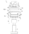
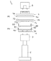
図1は、第1実施例におけるペリクル貼付装置1の要部を示す正面図である。図1において、ペリクル貼付装置1は水平式である。ペリクル貼付装置1においてフォトマスク70は水平に保持される。ペリクル貼付装置1は、下から上に向けて、下側エアシリンダ2、下側ベース部材3、ペリクル加圧体4、マスク加圧体50、及び上側ベース部材6を備えている。下側エアシリンダ2及び上側ベース部材6は、ペリクル貼付装置1のフレーム(図示せず)に固定されている。(First embodiment)
FIG. 1 is a front view showing a main part of a
ペリクル加圧体4とマスク加圧体50との間には、下側のペリクル組立体80と、上側のフォトマスク70と、が配置される。ここで、ペリクル組立体80は、ペリクル加圧体4の上に載っており、フォトマスク70は、フォトマスク70を支持するための枠状のステージ(図示せず)の上に載っている。フォトマスク70において、ガラス面72は上側に面しており、クロム面71は下側に面している。クロム面71の中央部には、露光パターン領域71aが形成されている。ペリクル組立体80は、ペリクル膜81と、ペリクルフレーム82と、から構成されている。ペリクルフレーム82の上面には接着剤層90が設けられている。
A
接着剤層90は、一般的に熱可塑性樹脂系接着剤をペリクルフレーム82の上面に塗布することによって、成形されている。
The
ペリクル貼付装置1において、下側エアシリンダ2の駆動によって、ペリクル加圧体4が上側に移動する。ペリクル加圧体4は、ペリクル組立体80を介してフォトマスク70を押し上げながら、上昇する。ペリクル加圧体4及びマスク加圧体50は一対の圧子を構成しており、これらの間に配置されているフォトマスク70とペリクル組立体80とが加圧される。この結果、接着剤層90によって、ペリクル組立体80がフォトマスク70に貼り付けられる。
In the
ペリクル貼付装置1は、ペリクル組立体80及びフォトマスク70のサイズの変更に対応できるように、構成されている。具体的には、ペリクル組立体80及びフォトマスク70の異なるサイズに対応して、異なるサイズのペリクル加圧体4及びマスク加圧体50が用意されている。また、ペリクル組立体80に応じてペリクル加圧体4を交換できるように、ペリクル加圧体4が下側ベース部材3に対して着脱自在である。フォトマスク70に応じてマスク加圧体50を交換できるように、マスク加圧体50が上側ベース部材6に対して着脱自在である。
The
ペリクル加圧体4は、金属(硬質アルミ)又はエンジニアリングプラスチックを機械加工することによって製造された成型品である。ペリクル加圧体4は、ペリクル組立体80のペリクルフレーム82のみに接触する突出部4aを有しており、ペリクルフレーム82のみを加圧する。突出部4aは、ペリクルフレーム82の形状に対応しており、四角形の枠状の部分である。
The pellicle
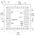
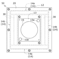
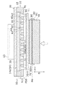
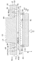
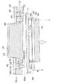
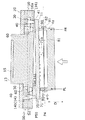
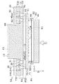
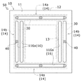
図2〜図5を参照して、マスク加圧体50を説明する。図2は、マスク加圧体を下側から見た下面図である。図3は、マスク加圧体を上側から見た上面図である。図4は、図2のA−A断面図(正面断面図)である。図5は、図2のB−B断面図(正面断面図)である。
The
図4において、マスク加圧体50は、本体10と、カバー体20と、緩衝材部材30と、複数の加圧ピン(接触部材)40と、複数のキャップピン(被覆部材)60と、を備えている。加圧ピン40は、フォトマスク70に直接接触する部品である。緩衝材部材30は、加圧ピン40を弾性的に支持する部材である。本体10及びカバー体20は、加圧ピン40及び緩衝材部材30を支持する。
In FIG. 4, the
以下において、マスク加圧体50の姿勢を、ペリクル貼付装置1における使用時の姿勢を基準として、説明する。例えば、図4の紙面の上側及び下側は、実際の鉛直方向に対応している。また、本実施形態では、マスク加圧体50及びペリクル加圧体4が、フォトマスク70及びペリクル組立体80を加圧する加圧方向Dは、鉛直方向である。
Below, the attitude | position of the
図2〜図4において、本体10は、底板部11と、側板部12と、基部13と、を備えている。底板部11は、板状部分である。底板部11の形状は、水平面内において、正方形に近い四角形である。側板部12は、底板部11の外周部を囲う四角形の枠状部材であり、底板部11から上方へ延びている。基部13は、底板部11の中央部から上方へ延びる柱状体である。
2 to 4, the
図2〜図4において、基部13の上面の中央部には、磁性体15が固定されている。また、基部13の上面の端部には、対角線上に2つの位置決め穴13a、13aが形成されている。一方、図1において、マスク加圧体50を支持する上側ベース部材6には、電磁石9(又は強磁性体)と、2つの位置決めピン6a、6aが設けられている。2つの位置決め穴13a、13a内に2つの位置決めピン6a、6aに挿入された状態で、電磁石9に磁性体15が固定されると、マスク加圧体50が上側ベース部材6に固定される。
2 to 4, a
図2〜図4において、本体10には、側板部12と基部13との間に、溝14が形成されている。溝14は、四角形の枠状の溝である。溝14は、4つの辺部として、第1辺部14a、14aと、第2辺部14b、14bと、を有している。第1辺部14a、14aは、前後に配置されている。第2辺部14b、14bは、左右に配置されている。第2辺部14bの幅は、第1辺部14aの幅よりも2倍程度大きい。
2 to 4, a
図2、図4において、底板部11は、開口部16を有している。開口部16は、多数(4以上)の貫通孔16aの集合である。貫通孔16aは、底板部11を鉛直方向に貫通している。貫通孔16aは、溝14の形成領域に沿って配置されている。第1辺部14aの形成領域において、貫通孔16aが一列配置されている。第2辺部14bの形成領域において、貫通孔16aが二列配置されている。貫通孔16aは、下底面B1及び上底面B2を有する円錐台形状の孔である。
2 and 4, the
図2において、加圧ピン40が、一部の貫通孔16aに挿入されている。図4において、加圧ピン40は、底板部11よりも下方に突出している。加圧ピン40は、円錐台状の軸部41と、円盤状の底部42と、からなっている。軸部41の長さは、底板部11の厚みh11よりも長い。軸部41の軸断面は、軸部41の中間部において下底面B1に等しく、軸部41の上端において上底面B2に等しい。軸部41及び貫通孔16aが共にテーパーであるので、加圧ピン40は、底板部11よりも下側(加圧方向Dの一側)に脱落しない。1つの加圧ピン40は、1つの貫通孔16aを閉鎖する。また、底部42の軸断面は、上底面B2よりも広い。底部42は、緩衝材部材30に接触する面積を広く確保するために、設けられている。このため、隣り合う加圧ピン40、40同士が接触しない程度に、底部42の大きさが最大限大きく設定されている。
In FIG. 2, the
図2において、キャップピン60が、一部の貫通孔16aに挿入されている。図4において、キャップピン60は、底板部11よりも下方には突出しない。キャップピン60も、円錐台状の軸部61と、円盤状の底部62と、からなっている。軸部61の長さは、底板部11の厚みh11に略等しい。軸部61の軸断面は、軸部61の下端において下底面B1に等しく、軸部41の上端において上底面B2に等しい。軸部61及び貫通孔16aも共にテーパーであるので、キャップピン60も、底板部11よりも下側(加圧方向Dの一側)に脱落しない。1つのキャップピン60は、1つの貫通孔16aを閉鎖する。また、底部62も、加圧ピン40の底部42と同様に、軸部41よりも幅広に形成されている。
In FIG. 2, the
図2において、緩衝材部材30は、溝14の形成領域に沿って、溝14内に配置されている。緩衝材部材30は、長手の板状の直方体である。第1辺部14aの形成領域において、緩衝材部材30が1つ配置されている。第2辺部14bの形成領域において、緩衝材部材30が平行に2つ配置されている。緩衝材部材30の下面は、加圧ピン40の底部42及びキャップピン60の底部62に接触している。
In FIG. 2, the
図4において、カバー体20は、本体10の上側(加圧方向Dの他側)に設けられている。より詳しくは、カバー体20は、側板部12の上に固定されている。図3において、カバー体20は、水平面内において、正方形に近い四角形の枠状部材である。カバー体20は、溝14を上方から被覆できる。このとき、鉛直方向において、緩衝材部材30が、下側の加圧ピン40及びキャップピン60と、上側のカバー体20とによって、位置決めされる。
In FIG. 4, the
図2を参照して、開口部16及び溝14の構成を説明する。マスク加圧体50は、従来のマスク加圧体5と同様に、フォトマスク70の面方向における外周部を加圧するように構成されている。ここで、マスク加圧体50による加圧部分は、フォトマスク70のガラス面72において、ペリクルフレーム82の真裏に対応する裏側部分、又は裏側部分の外側にある外側部分である。本実施形態では、第1辺部14a内の一列の貫通孔16aは、ガラス面72の裏側部分に近い外側部分(以下、略裏側部分)に対応している。第2辺部14b内の内側の一列における貫通孔16aも、ガラス面72の裏側部分に対応している。第2辺部14b内の外側の一列における貫通孔16aは、ガラス面72の外側部分に対応している。
With reference to FIG. 2, the structure of the
図2において、8つの加圧ピン40が、2つの第1辺部14aと、2つの第2辺部14bの外側部分とに、配置されている。つまり、図2における加圧ピン40の配置は、ペリクルフレーム82の略裏側部分と、ペリクルフレーム82の外側部分と、を加圧するように、設定されている。8つの加圧ピン40の位置は、四角形の頂点位置及び各辺の中点位置である。また、残りの貫通孔16aには、キャップピン60が配置されている。このようにして、加圧ピン40及びキャップピン60によって、開口部16内の貫通孔16aの全てが閉鎖されている。
In FIG. 2, eight pressure pins 40 are disposed on the two
図6〜図9を参照して、マスク加圧体50の作動を説明する。図6、図7は、ピン40、60の配置における第1使用例を示している。図8、図9は、ピン40、60の配置における第2使用例を示している。
The operation of the
上述したように、マスク加圧体50は、複数の加圧ピン40及びキャップピン60を備えている。このため、開口部16内に配置する加圧ピン40の数及び位置を適宜調整することが可能である。開口部16内に配置される加圧ピン40の数及び位置によって、マスク加圧体50が加圧荷重を受けたときのマスク加圧面P50の傾きが変化する。
As described above, the
第1使用例は、図2に示されるように、開口部16内に加圧ピン40が均一に配置された場合を示している。
As shown in FIG. 2, the first usage example shows a case where the pressure pins 40 are uniformly arranged in the
図6は、加圧処理の開始直後におけるマスク加圧体50を見た正面断面図である。開始直後とは、フォトマスク70及びペリクル組立体80が、ペリクル加圧体4及びマスク加圧体50によって挟まれた直後を指している。つまり、この開始時点以降に、フォトマスク70とペリクル組立体80との間の接着剤層90に、加圧荷重が加わる。
FIG. 6 is a front sectional view of the
図6において、ペリクル加圧面P4は右上がりであり、マスク加圧面P50は右下がりである。ペリクル貼付装置1における機械加工精度及び組立精度のため、ペリクル加圧面P4とマスク加圧面P50との平行度は、ゼロではない。ここで、ペリクル加圧面P4は、ペリクル加圧体4においてペリクルフレーム82に接触する面であり、突出部4aの上面を指している。マスク加圧面P50は、マスク加圧体50においてフォトマスク70に接触する面であり、各加圧ピン40の下端位置を通過する面を指している。図6に示される時点において、フォトマスク70及びペリクル組立体80の右端部のみが、ペリクル加圧面P4及びマスク加圧体50によって挟まれている。この結果、加圧荷重Fは、フォトマスク70及びペリクル組立体80の右端部にのみ掛かっている。
In FIG. 6, the pellicle pressure surface P4 is raised to the right, and the mask pressure surface P50 is lowered to the right. Due to the machining accuracy and assembly accuracy in the
図7は、加圧処理の開始後におけるマスク加圧体50を見た正面断面図である。ペリクル加圧体4が図6の状態よりも上昇することによって、加圧処理が進行する。ここで、加圧方向Dにおいて、接着剤層90だけでなく、緩衝材部材30が、変形しうる。このため、接着剤層90及び緩衝材部材30の変形によって、ペリクル加圧体4がより上方に移動できる。この結果、ペリクル加圧体4及びマスク加圧体50によって、ペリクルフレーム82及びフォトマスク70が、右端部だけでなく左端部も含む全体において、加圧される。図7において、ペリクルフレーム82及びフォトマスク70の右側には加圧荷重FRが加わっており、ペリクルフレーム82及びフォトマスク70の左側には加圧荷重FLが加わっている。
FIG. 7 is a front sectional view of the
加圧荷重は、一対の加圧面P4、P50間の距離に応じて、異なっている。加圧面P4、P50間の距離が近い部分は、加圧面P4、P50間の距離が遠い部分よりも、大きく加圧荷重を受ける。したがって、図7において、右側の加圧荷重FRは、左側の加圧荷重FLよりも、大きい。 The pressure load varies depending on the distance between the pair of pressure surfaces P4 and P50. The portion where the distance between the pressurization surfaces P4 and P50 is short receives a greater pressure load than the portion where the distance between the pressurization surfaces P4 and P50 is far. Therefore, in FIG. 7, the right side pressure load FR is larger than the left side pressure load FL.
本実施形態のマスク加圧体50では、緩衝材部材30が変形できる。図6の状態から図7の状態に移行する間、右側の加圧荷重FRは徐々に小さくなっていくが、右側の加圧荷重FRは常に左側の加圧荷重FLよりも大きい。左側および右側の緩衝材部材30も、当然ながら、加圧荷重の大きさに応じて、変形する。したがって、右側の緩衝材部材30の変形量は、左側の緩衝材部材30の変形量よりも、大きい。変形量差S1は、左右における変形量の差である。このように、緩衝材部材30が変形することによって、一対の加圧面P4、P50間の平行度が、図6の開始時(初期値)よりも図7の加圧処理中(実際値)において、小さくなっている。
In the
図7において、一対の加圧面P4、P50間の平行度がゼロではないため、接着剤層90の左右にも変形量差が発生する。しかし、一対の加圧面P4、P50間の平行度が小さくされているので、接着剤層90の左右における変形量差も小さくなっている。このため、緩衝材部材30を有しない従来のマスク加圧体を用いる場合と比べて、本実施形態のマスク加圧体50を用いる場合は、面方向における接着剤層90の変形量の不均一さを小さくできる。
In FIG. 7, since the parallelism between the pair of pressure surfaces P4 and P50 is not zero, a difference in deformation also occurs between the left and right sides of the
更に、緩衝材部材30の圧縮弾性率(硬さ、柔らかさの程度)及び厚みを適宜変更することによって、緩衝材部材30の変形量を変更できる。特に、緩衝材部材30の変形量を大きくすることによって、接着剤層90の変形量を小さくできる。つまり、加圧荷重の偏りを緩衝材部材30により一層吸収させることによって、接着剤層90に及ぶ加圧荷重の偏りの影響を、低減できる。
Furthermore, the amount of deformation of the
第2使用例は、図8に示されるように、開口部16内に加圧ピン40が部分的に不均一に配置された場合を示している。作業者は、第1使用例をペリクル貼付装置1に適用した結果に基づいて、ペリクル貼付装置1における加圧荷重の偏りの傾向を、把握できる。具体的には、加圧荷重を検出できる検出機器を用いて、接着剤層90の面方向における各部に掛かる加圧荷重を計測することによって、加圧荷重の偏りの傾向が把握される。そこで、第2使用例では、加圧荷重の不均一さに対応するように、加圧ピン40が配置されている。
In the second usage example, as shown in FIG. 8, the
図8において、7つの加圧ピン40が配置されている。加圧ピン40は、中央及び左側にはそれぞれ3つ配置されているが、右側には2つしか配置されていない。このため、マスク加圧体50の左右に均一な加圧荷重が加わった場合、右側の緩衝材部材30の変形量が、左側の緩衝材部材30の変形量よりも大きくなる。つまり、第2使用例の加圧面P50は、第1使用例の加圧面P50よりも、右上がりになり易い。
In FIG. 8, seven
図9は、加圧処理の開始後におけるマスク加圧体50を見た正面断面図である。図9は、図7に対応している。図9において、変形量差S2は、左側における変形量の差である。第2使用例の変形量差S2は、第1使用例の変形量差S1よりも大きい。これは、第2使用例では、右側の加圧ピン40の数が、左側の加圧ピン40よりも少ないためである。ここで、加圧ピン40の数に応じて、加圧ピン40と緩衝材部材30との接触面積が変化する。第2使用例においては、右側における接触面積は、左側の接触面積の2/3である。接触面積が小さくなるほど、緩衝材部材30の単位面積当たりに加わる加圧荷重が大きくなる。つまり、右側の緩衝材部材30において加圧ピン40に接触している部分は、左側の緩衝材部材30において加圧ピン40に接触している部分よりも、変形しやすい。したがって、右側の加圧ピン40の方が、左側の加圧ピン40よりも、加圧方向Dに移動しやすい。この結果、一対の加圧面P4、P50間の平行度を、第1使用例よりも、小さくできる。このため、接着剤層90の左右における変形量差を、第1使用例よりも小さくできる。
FIG. 9 is a front sectional view of the
作業者は、第1使用例の結果に基づいて、第2使用例の配置を決定することができる。第1使用例では、加圧ピン40が、加圧面P50の面方向において均一に配置されている。加圧処理の結果として、接着剤層90の変形量に面方向において偏りが発生していれば、一対の加圧体P4、P50間の平行度がゼロでないことが明らかである。この場合、作業者は、その偏りを小さくするように、加圧ピン40の配置を変更する。このようにして、一対の加圧体P4、P50間の平行度をゼロに近づけることができる。
The operator can determine the arrangement of the second usage example based on the result of the first usage example. In the first usage example, the pressure pins 40 are arranged uniformly in the surface direction of the pressure surface P50. If the deformation amount of the
上記構成のマスク加圧体50によれば、一対の加圧体P4、P50間に作用する加圧荷重に応じて、緩衝材部材30が変形するので、加圧処理中の平行度(実際値)を、機械加工精度及び組立精度によって発生する平行度(初期値)よりも小さくできる。この結果、接着剤層90に加わる加圧荷重を、面方向において均一に近づけることができる。
According to the
更に、マスク加圧面P50の面方向における加圧荷重の偏りに応じて、マスク加圧体50内に配置する加圧ピン40の数及び位置を適宜調整することによって、加圧処理中の平行度(実際値)を、より一層小さくすることができる。
Furthermore, by adjusting the number and position of the pressure pins 40 arranged in the
マスク加圧体50は、キャップピン60を備えている。このため、緩衝材部材30から塵挨が発生しても、その塵挨が開口部16から外部に排出されることを防止できる。
The
貫通孔16aの内面、加圧ピン40の外面、及びキャップピン60の外面が、テーパー状である。このため、加圧ピン40及びキャップピン60が加圧方向Dに移動するときに、加圧ピン40及びキャップピン60が貫通孔16aに摩擦接触しない。したがって、加圧ピン40及びキャップピン60が加圧方向Dに移動しても、塵挨の発生が防止される。
The inner surface of the through-
マスク加圧体50は、加圧ピン40の配置において、次の変形例を適用できる。
The
開口部16は、ペリクルフレーム82の真裏に対応する裏側部分、又は裏側部分の外側にある外側部分に対応して、設定されている。上述の第1及び第2使用例は、裏側部分及び外側部分の双方を加圧する場合を示している。
The
図10は、第3使用例のマスク加圧体50を示している。図10において、加圧ピン40が裏側部分のみを加圧するように、開口部16に加圧ピン40が配置されている。つまり、加圧ピン40が、第2辺部14b内の内側の一列における貫通孔16aに配置されている。この場合、加圧処理におけるフォトマスク70の歪みの発生を、より一層、低減できる。
FIG. 10 shows the
マスク加圧体50内に配置する加圧ピン40の数は、最低3つである。3つあれば、マスク加圧体50は、フォトマスク70を加圧できる。作業者は、加圧処理の結果を参照することによって、加圧ピン40の数を4以上に変更し、且つ、加圧ピン40の位置を適宜設定することができる。このようにして、作業者は、一対の加圧面P4、P50間の平行度を限りなくゼロに近づけることができる。
The number of pressure pins 40 arranged in the
(他の実施例)
マスク加圧体50は、次の変形構成を適用できる。(Other examples)
For the
加圧ピン40は、マスク加圧面P50を構成する接触部材の一例である。また、キャップピン60は、開口部16を閉鎖する被覆部材の一例である。接触部材及び被覆部材は、開口部16から抜け落ちない形状を有していればよく、ピン(軸部材)に限定されない。接触部材及び被覆部材の形状は、例えば、球体であってもよい。
The
本実施形態では、開口部16は、ペリクルフレーム82に対応するように、平面視において四角形状に形成されている。しかし、この構成に限定されない。開口部16の位置は、加圧ピン40がフォトマスク70を少なくとも3点で支持できるように、設定されていればよい。このため、貫通孔16aの全てが同一直線上に配置されることはない。
In the present embodiment, the
加圧ピン40は、加圧処理における加圧荷重によって変形しない硬度を有している。このため、加圧ピン40がフォトマスク70のガラス面72に接触した後に、ガラス面72に接触痕(タッチマーク)が残りにくい。したがって、ガラス面72が、加圧ピン40によって、汚染されにくい。加圧ピン40の素材として、例えば、エンジニアリングプラスチックである、PEEK(登録商標)、ベスペル(登録商標)、及びPBI(ポリベンゾイミダゾール)が利用できる。
The
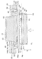
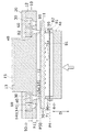
図11は、第2実施例における、図2のA−A断面図(正面断面図)である。図11において、左側の溝14(第2辺部14b)には、緩衝材部材31及び敷板39が設けられている。緩衝材部材31及び敷板39を合わせた加圧方向Dにおける厚みは、緩衝材部材30の厚みT30に等しい。つまり、緩衝材部材31の厚みT31は、緩衝材部材30の厚みT30よりも小さい。
FIG. 11 is a cross-sectional view (front cross-sectional view) taken along line AA of FIG. 2 in the second embodiment. In FIG. 11, a
このため、左側の緩衝材部材31及び右側の緩衝材部材30に同一の加圧荷重が加えられた場合に、左側の緩衝材部材31の変形量が、右側の緩衝材部材30の変形量よりも小さくなる。したがって、厚みの異なる緩衝材部材30、31を用いることによって、異なる位置にある緩衝材部材30、31の加圧方向における変形量を、異ならせることができる。
For this reason, when the same pressure load is applied to the
厚みではなく、素材の異なる緩衝材部材30、31を用いる場合も、異なる位置にある緩衝材部材の加圧方向における変形量を、異ならせることができる。
Even when the
なお、加圧荷重や接着剤層90の変更などに対応するために、加圧体50内に配置する全ての緩衝材部材30について、厚みや素材を変更してもよい。
In addition, in order to cope with a change in the pressure load, the
本実施形態では、1つの緩衝材部材30が複数の貫通孔16aに対応するように、緩衝材部材30の寸法が設定されている。この構成に代えて、各加圧ピン40に、例えば、底部42に対応する大きさの緩衝材部材30を、固定しても良い。つまり、加圧ピン40の数に応じて、加圧荷重を受ける部位の緩衝材部材30の面積が増大する構成であれば、他の構成を適用してもよい。
In the present embodiment, the size of the
また、図11において、緩衝材部材30、31の厚みの差をカバーするために、敷板39が用いられている。敷板39の代わりに、異なる軸方向長さを有する加圧ピン40及びキャップピン60を、用いてもよい。つまり、カバー体20の下面からマスク加圧面P50までの距離が一定であればよい。加圧方向Dにおける、加圧ピン40(キャップピン60)、緩衝材部材、及び敷板の合計長さが、加圧面P50の面方向において等しければよい。
Further, in FIG. 11, a
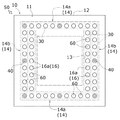
図12は、第3実施例における、マスク加圧体を下側から見た下面図である。図12において、開口部16が、貫通孔16aに代えて、長孔116aによって構成されている。長孔116aによって構成される開口部16においても、加圧ピン40の位置を変更することが可能である。マスク加圧体50がフォトマスク70を3点で支持できるように、開口部16は、3以上の長孔116aの集合によって構成されている。
FIG. 12 is a bottom view of the mask pressurizing body as viewed from below in the third embodiment. In FIG. 12, the
以上においては、加圧ピン40及び緩衝材部材30を備えた本発明の加圧体を、マスク加圧体50に適用した例を示している。しかし、本発明の加圧体は、ペリクル加圧体4に適用することもできる。更に、一対の加圧体4、50の双方に、本発明の加圧体を、適用することもできる。
In the above, the example which applied the pressurization body of the present invention provided with
1 ペリクル貼付装置
2 下側エアシリンダ(アクチュエータ)
10 本体
16 開口部
16a 貫通孔
20 カバー体
30 緩衝材部材
40 加圧ピン(接触部材)
60 キャップピン(被覆部材)
70 フォトマスク
80 ペリクル組立体
81 ペリクル膜
D 加圧方向
P4 ペリクル加圧面
P50 マスク加圧面1
DESCRIPTION OF
60 Cap pin (coating material)
70
Claims (9)
前記加圧方向の一側において、前記フォトマスク又は前記ペリクル組立体に接触するための、3以上の接触部材と、
前記接触部材を前記一側に脱落不能に支持し、且つ、前記接触部材を支持する位置を前記加圧方向に直交する平面内で変更可能とする、開口部が形成された、本体と、
前記加圧方向の他側において、前記本体に固定される、カバー体と、
前記加圧方向において、前記接触部材と前記カバー体との間に配置される、緩衝材部材と、
を備えている。In a pressurizing body for pressurizing a pellicle assembly constituted by a photomask, a pellicle film and a pellicle frame that supports the pellicle film along a predetermined pressing direction,
Three or more contact members for contacting the photomask or the pellicle assembly on one side of the pressing direction;
A body formed with an opening that supports the contact member on the one side so as not to fall off and allows the position for supporting the contact member to be changed within a plane perpendicular to the pressing direction;
A cover body fixed to the main body on the other side in the pressing direction;
A buffer member disposed between the contact member and the cover body in the pressurizing direction;
It has.
前記開口部に前記一側に脱落不能に支持されると共に、前記開口部を閉鎖するように前記接触部材と並べて配置されることによって、前記緩衝材部材が前記一側に露出するのを防止する、被覆部材を、更に備えている。It is a pressurization object according to claim 1, Comprising:
The opening is supported on the one side so as not to fall off, and is arranged side by side with the contact member so as to close the opening, thereby preventing the cushioning member from being exposed to the one side. And a covering member.
前記開口部が、4以上の貫通孔の集合である。It is a pressurization object according to claim 2, Comprising:
The opening is a set of four or more through holes.
複数の前記被覆部材を備えており、
1つの前記接触部材及び1つの前記被覆部材が、それぞれ、1つの前記貫通孔を閉鎖できる寸法を有している。It is a pressurization object according to claim 3,
A plurality of the covering members,
Each of the one contact member and the one covering member has a dimension capable of closing the one through hole.
前記貫通孔の内面がテーパー状であり、
前記接触部材及び前記被覆部材が、前記貫通孔の内面に対応するテーパー状の外面を有している。It is a pressurization object according to claim 4, Comprising:
The inner surface of the through hole is tapered,
The contact member and the covering member have a tapered outer surface corresponding to the inner surface of the through hole.
複数の前記緩衝材部材を備えており、
前記各緩衝材部材が、前記平面に沿って異なる位置に配置されている。It is a pressurization object according to claim 1, Comprising:
A plurality of the cushioning member,
Each said buffer material member is arrange | positioned in the position which differs along the said plane.
前記緩衝材部材の素材が、前記位置に応じて異なっている。It is a pressurization object according to claim 6, Comprising:
The material of the cushioning member is different depending on the position.
前記緩衝材部材の前記加圧方向における厚みが、前記位置に応じて異なっている。It is a pressurization object according to claim 6, Comprising:
The thickness of the cushioning member in the pressurizing direction varies depending on the position.
前記一対の加圧体の少なくとも一方を、前記加圧方向に沿って付勢可能なアクチュエータと、
を備えている、ペリクル貼付装置であって、
前記一対の加圧体の少なくとも一方が、請求項1〜8のいずれか1つに記載の加圧体である。A pair of pressurizing bodies for pressurizing a pellicle assembly constituted by a photomask, a pellicle film, and a pellicle frame supporting the pellicle film along a predetermined pressurizing direction;
An actuator capable of biasing at least one of the pair of pressurizing bodies along the pressurizing direction;
A pellicle sticking device comprising:
At least one of the pair of pressure bodies is the pressure body according to any one of claims 1 to 8.
Applications Claiming Priority (1)
| Application Number | Priority Date | Filing Date | Title |
|---|---|---|---|
| PCT/JP2009/060084 WO2010140223A1 (en) | 2009-06-02 | 2009-06-02 | Pressing body and pellicle sticking device |
Publications (2)
| Publication Number | Publication Date |
|---|---|
| JP5037726B2 true JP5037726B2 (en) | 2012-10-03 |
| JPWO2010140223A1 JPWO2010140223A1 (en) | 2012-11-15 |
Family
ID=43297369
Family Applications (1)
| Application Number | Title | Priority Date | Filing Date |
|---|---|---|---|
| JP2011518116A Active JP5037726B2 (en) | 2009-06-02 | 2009-06-02 | Pressurized body and pellicle sticking device |
Country Status (3)
| Country | Link |
|---|---|
| JP (1) | JP5037726B2 (en) |
| KR (1) | KR101318147B1 (en) |
| WO (1) | WO2010140223A1 (en) |
Families Citing this family (3)
| Publication number | Priority date | Publication date | Assignee | Title |
|---|---|---|---|---|
| JP5600921B2 (en) * | 2009-10-19 | 2014-10-08 | 凸版印刷株式会社 | Pellicle sticking device |
| WO2012172642A1 (en) * | 2011-06-14 | 2012-12-20 | 松下精機株式会社 | Pellicle application device |
| US10455549B2 (en) * | 2013-06-25 | 2019-10-22 | Nokia Solutions And Networks Oy | Control of resources |
Citations (3)
| Publication number | Priority date | Publication date | Assignee | Title |
|---|---|---|---|---|
| JPH09146261A (en) * | 1995-11-20 | 1997-06-06 | Nikon Corp | Automatic pellicle pasting device |
| JP2005165170A (en) * | 2003-12-05 | 2005-06-23 | Matsushita Seiki Kk | Pellicle sticking apparatus for fpd mask |
| JP2009058956A (en) * | 2007-08-29 | 2009-03-19 | Samsung Electronics Co Ltd | Pellicle adhesion apparatus and pellicle adhesion method using the same |
-
2009
- 2009-06-02 KR KR1020117026915A patent/KR101318147B1/en active Active
- 2009-06-02 JP JP2011518116A patent/JP5037726B2/en active Active
- 2009-06-02 WO PCT/JP2009/060084 patent/WO2010140223A1/en not_active Ceased
Patent Citations (3)
| Publication number | Priority date | Publication date | Assignee | Title |
|---|---|---|---|---|
| JPH09146261A (en) * | 1995-11-20 | 1997-06-06 | Nikon Corp | Automatic pellicle pasting device |
| JP2005165170A (en) * | 2003-12-05 | 2005-06-23 | Matsushita Seiki Kk | Pellicle sticking apparatus for fpd mask |
| JP2009058956A (en) * | 2007-08-29 | 2009-03-19 | Samsung Electronics Co Ltd | Pellicle adhesion apparatus and pellicle adhesion method using the same |
Also Published As
| Publication number | Publication date |
|---|---|
| KR101318147B1 (en) | 2013-10-15 |
| KR20130053357A (en) | 2013-05-23 |
| WO2010140223A1 (en) | 2010-12-09 |
| JPWO2010140223A1 (en) | 2012-11-15 |
Similar Documents
| Publication | Publication Date | Title |
|---|---|---|
| US8159654B2 (en) | Pressure body and pellicle mounting apparatus | |
| US9892949B2 (en) | Imprint method, imprint apparatus, and article manufacturing method | |
| JP5395769B2 (en) | Template chuck, imprint apparatus, and pattern forming method | |
| KR101325762B1 (en) | Optical inspection device | |
| US9568819B2 (en) | Holding apparatus, imprint apparatus and article manufacturing method using same | |
| KR20110089071A (en) | Lithography pellicle and its manufacturing method | |
| JP5037726B2 (en) | Pressurized body and pellicle sticking device | |
| US20110198769A1 (en) | Imprint apparatus and article manufacturing method | |
| US20160016354A1 (en) | Mold, imprint apparatus, and article manufacturing method | |
| US20150261104A1 (en) | Electrostatic chuck cleaner, cleaning method, and exposure apparatus | |
| KR20170086405A (en) | Substrate holding apparatus, lithography apparatus, photomask testing apparatus, and photomask manufacturing method | |
| TWI412883B (en) | Pressure body and pellicle mounting apparatus | |
| JP2011017833A (en) | Device for sticking pellicle and method for sticking pellicle, and mask with pellicle | |
| WO2017038788A1 (en) | Article-holding device, exposure device, method for manufacturing flat panel display, method for manufacturing device, method for holding article, and exposure method | |
| JP2012058400A (en) | Manufacturing method of pellicle | |
| JP5328495B2 (en) | Imprint apparatus and article manufacturing method | |
| JP6874314B2 (en) | Object holding device, exposure device, flat panel display manufacturing method, and device manufacturing method | |
| JP2023173638A (en) | Substrate processing equipment | |
| JP6231576B2 (en) | Semiconductor processing apparatus and semiconductor processing method | |
| JP2011085831A (en) | Pellicle sticking device, method for sticking pellicle, and mask with pellicle | |
| JP2007331041A (en) | Flat work equipment | |
| JP2004219934A (en) | Substrate bonding apparatus and substrate bonding method | |
| JP2007299925A (en) | Stage apparatus and exposure apparatus | |
| KR101773556B1 (en) | The position alignment device and the method using the same | |
| KR20260008748A (en) | Substrate support |
Legal Events
| Date | Code | Title | Description |
|---|---|---|---|
| TRDD | Decision of grant or rejection written | ||
| A01 | Written decision to grant a patent or to grant a registration (utility model) |
Free format text: JAPANESE INTERMEDIATE CODE: A01 Effective date: 20120605 |
|
| A01 | Written decision to grant a patent or to grant a registration (utility model) |
Free format text: JAPANESE INTERMEDIATE CODE: A01 |
|
| A61 | First payment of annual fees (during grant procedure) |
Free format text: JAPANESE INTERMEDIATE CODE: A61 Effective date: 20120704 |
|
| FPAY | Renewal fee payment (event date is renewal date of database) |
Free format text: PAYMENT UNTIL: 20150713 Year of fee payment: 3 |
|
| R150 | Certificate of patent or registration of utility model |
Ref document number: 5037726 Country of ref document: JP Free format text: JAPANESE INTERMEDIATE CODE: R150 Free format text: JAPANESE INTERMEDIATE CODE: R150 |
|
| R250 | Receipt of annual fees |
Free format text: JAPANESE INTERMEDIATE CODE: R250 |
|
| R250 | Receipt of annual fees |
Free format text: JAPANESE INTERMEDIATE CODE: R250 |
|
| R250 | Receipt of annual fees |
Free format text: JAPANESE INTERMEDIATE CODE: R250 |
|
| R250 | Receipt of annual fees |
Free format text: JAPANESE INTERMEDIATE CODE: R250 |
|
| R250 | Receipt of annual fees |
Free format text: JAPANESE INTERMEDIATE CODE: R250 |
|
| R250 | Receipt of annual fees |
Free format text: JAPANESE INTERMEDIATE CODE: R250 |
|
| R250 | Receipt of annual fees |
Free format text: JAPANESE INTERMEDIATE CODE: R250 |
|
| R250 | Receipt of annual fees |
Free format text: JAPANESE INTERMEDIATE CODE: R250 |
|
| R250 | Receipt of annual fees |
Free format text: JAPANESE INTERMEDIATE CODE: R250 |
|
| R250 | Receipt of annual fees |
Free format text: JAPANESE INTERMEDIATE CODE: R250 |
|
| R250 | Receipt of annual fees |
Free format text: JAPANESE INTERMEDIATE CODE: R250 |