JP5033242B2 - Washing machine - Google Patents
Washing machine Download PDFInfo
- Publication number
- JP5033242B2 JP5033242B2 JP2010532991A JP2010532991A JP5033242B2 JP 5033242 B2 JP5033242 B2 JP 5033242B2 JP 2010532991 A JP2010532991 A JP 2010532991A JP 2010532991 A JP2010532991 A JP 2010532991A JP 5033242 B2 JP5033242 B2 JP 5033242B2
- Authority
- JP
- Japan
- Prior art keywords
- stator
- tightening
- washing machine
- tab
- bearing housing
- Prior art date
- Legal status (The legal status is an assumption and is not a legal conclusion. Google has not performed a legal analysis and makes no representation as to the accuracy of the status listed.)
- Expired - Fee Related
Links
Images


Classifications
-
- D—TEXTILES; PAPER
- D06—TREATMENT OF TEXTILES OR THE LIKE; LAUNDERING; FLEXIBLE MATERIALS NOT OTHERWISE PROVIDED FOR
- D06F—LAUNDERING, DRYING, IRONING, PRESSING OR FOLDING TEXTILE ARTICLES
- D06F37/00—Details specific to washing machines covered by groups D06F21/00 - D06F25/00
- D06F37/20—Mountings, e.g. resilient mountings, for the rotary receptacle, motor, tub or casing; Preventing or damping vibrations
- D06F37/206—Mounting of motor
-
- D—TEXTILES; PAPER
- D06—TREATMENT OF TEXTILES OR THE LIKE; LAUNDERING; FLEXIBLE MATERIALS NOT OTHERWISE PROVIDED FOR
- D06F—LAUNDERING, DRYING, IRONING, PRESSING OR FOLDING TEXTILE ARTICLES
- D06F37/00—Details specific to washing machines covered by groups D06F21/00 - D06F25/00
- D06F37/26—Casings; Tubs
- D06F37/261—Tubs made by a specially selected manufacturing process or characterised by their assembly from elements
- D06F37/262—Tubs made by a specially selected manufacturing process or characterised by their assembly from elements made of plastic material, e.g. by injection moulding
-
- D—TEXTILES; PAPER
- D06—TREATMENT OF TEXTILES OR THE LIKE; LAUNDERING; FLEXIBLE MATERIALS NOT OTHERWISE PROVIDED FOR
- D06F—LAUNDERING, DRYING, IRONING, PRESSING OR FOLDING TEXTILE ARTICLES
- D06F37/00—Details specific to washing machines covered by groups D06F21/00 - D06F25/00
- D06F37/26—Casings; Tubs
- D06F37/267—Tubs specially adapted for mounting thereto components or devices not provided for in preceding subgroups
- D06F37/269—Tubs specially adapted for mounting thereto components or devices not provided for in preceding subgroups for the bearing of the rotary receptacle
-
- D—TEXTILES; PAPER
- D06—TREATMENT OF TEXTILES OR THE LIKE; LAUNDERING; FLEXIBLE MATERIALS NOT OTHERWISE PROVIDED FOR
- D06F—LAUNDERING, DRYING, IRONING, PRESSING OR FOLDING TEXTILE ARTICLES
- D06F37/00—Details specific to washing machines covered by groups D06F21/00 - D06F25/00
- D06F37/30—Driving arrangements
- D06F37/304—Arrangements or adaptations of electric motors
-
- Y—GENERAL TAGGING OF NEW TECHNOLOGICAL DEVELOPMENTS; GENERAL TAGGING OF CROSS-SECTIONAL TECHNOLOGIES SPANNING OVER SEVERAL SECTIONS OF THE IPC; TECHNICAL SUBJECTS COVERED BY FORMER USPC CROSS-REFERENCE ART COLLECTIONS [XRACs] AND DIGESTS
- Y10—TECHNICAL SUBJECTS COVERED BY FORMER USPC
- Y10T—TECHNICAL SUBJECTS COVERED BY FORMER US CLASSIFICATION
- Y10T29/00—Metal working
- Y10T29/53—Means to assemble or disassemble
Description
本発明は、洗濯機及び洗濯機の組立方法に係り、特に、洗濯作動中に発生する騒音及び振動が低減するとともに、モーターがしっかりと取り付けられるように構成された洗濯機に関するものである。 The present invention relates to a washing machine and a method for assembling the washing machine, and more particularly, to a washing machine configured to reduce noise and vibration generated during a washing operation and to which a motor is firmly attached.
図1は、従来技術による洗濯機の構成を示す縦断面図であり、図2は、図1におけるA部の拡大詳細図で、従来技術による洗濯機における駆動部の構造を示す縦断面図である。 FIG. 1 is a longitudinal sectional view showing a configuration of a washing machine according to the prior art, and FIG. 2 is an enlarged detailed view of a portion A in FIG. 1, and a longitudinal sectional view showing a structure of a drive unit in the washing machine according to the prior art. is there.
図1及び図2を参照すると、従来技術による洗濯機は、キャビネット1の内側に設置されるタブ2と、タブ2の内側に設置されるドラム3と、ドラム3に軸支されて、モーター5の駆動力をドラム3に伝達するシャフト4と、シャフト4の両端部において外周面上に設置されるベアリングと、を備える。タブ2の背壁部30の中央には、シャフト4の両端部に設置されるベアリングを支持するためのベアリングハウジング7が設けられる。ここで、ベアリングハウジング7は、タブ2の射出成形時にインサートされる。
Referring to FIGS. 1 and 2, a washing machine according to the prior art includes a
一方、シャフト4の後端部の中心にはロータ13が締め付けられ、ロータ13の内側においてタブ2の背壁部30にステータ14が締め付けられて、直結式モーター5を構成する。
On the other hand, the
タブ2の背壁部30上には、タブ2の射出成形時にベアリングハウジング7がその内部にインサートされるハブ31が設けられ、ハブ31の外側には締付け部材15aを用いてステータ14をタブ2の背壁部30上に固定させるための締付け用ボス32が、円周方向に沿って等間隔で設けられる。
A
タブ2の背壁部30とステータ14との間には、ステータ14を支持するサポータ17が介在される。サポータ17をタブの背壁部30に取り付けるために、サポータ17の外周面の内側には複数個の締付け部材15dが結合され、サポータ17にステータ14を固定するために別の締付け部材15aを有する。
A
従来技術による洗濯機は、タブの背壁部にサポータが設置された後に、このサポータにステータが設置されるので、それぞれの部材を締め付けるためのボス及び締付け部材が要求され、装着構造が複雑になるという問題点があった。 In the conventional washing machine, since the supporter is installed on the back wall of the tab, the stator is installed on the supporter. Therefore, a boss and a fastening member for fastening each member are required, and the mounting structure is complicated. There was a problem of becoming.
また、従来技術による洗濯機は、プラスチックタブにサポータが設置されるので、サポータを締め付ける作業時に外力によりタブが歪むことがあり、ステータが正確な位置を外れて固定されるため、同心度も維持し難く、しかも、洗濯作動中に部品間に干渉が生じ、騒音及び振動につながることがある。したがって、これらの従来の洗濯機における問題を解決するための方案が要求されている。 Also, in the washing machine according to the prior art, since the supporter is installed on the plastic tab, the tab may be distorted by an external force during the work of tightening the supporter, and the concentricity is maintained because the stator is fixed out of the correct position. In addition, interference may occur between parts during washing operations, leading to noise and vibration. Therefore, a method for solving the problems in these conventional washing machines is required.
本発明は上記の点に鑑みてなされたもので、その目的は、装着構造を単純化することによって設置作業に要求される部品数を減少できる洗濯機及び洗濯機の組立方法を提供することにある。 The present invention has been made in view of the above points, and an object thereof is to provide a washing machine and a method for assembling the washing machine that can reduce the number of parts required for installation work by simplifying the mounting structure. is there.
また、本発明の他の目的は、装着構造を改善することによって、部品を正確な位置に組み立てることができる洗濯機及び洗濯機の組立方法を提供することにある。 Another object of the present invention is to provide a washing machine and a washing machine assembling method capable of assembling parts at accurate positions by improving the mounting structure.
また、本発明のさらに他の目的は、駆動中に発生する騒音や振動を低減できる洗濯機及び洗濯機の組立方法を提供することにある。 It is still another object of the present invention to provide a washing machine and a method for assembling the washing machine that can reduce noise and vibration generated during driving.
また、本発明のさらに他の目的は、部材間の締付け強度を向上させることができる洗濯機及び洗濯機の組立方法を提供することにある。 It is still another object of the present invention to provide a washing machine and a method for assembling the washing machine that can improve the tightening strength between members.
また、本発明のさらに他の目的は、部材間の結合構造を改善することによって、組立性を向上させることができる洗濯機及び洗濯機の組立方法を提供することにある。 Another object of the present invention is to provide a washing machine and a method for assembling the washing machine that can improve the assemblability by improving the connecting structure between the members.
本発明の一側面による洗濯機は、タブと;前記タブの外部に締付け部が露出されるように前記タブにインサート射出されるベアリングハウジングと;前記締付け部に結合されるステータと;を含む。 A washing machine according to an aspect of the present invention includes a tab; a bearing housing that is insert-injected into the tab such that the tightening portion is exposed to the outside of the tab; and a stator that is coupled to the tightening portion.
また、前記締付け部は、前記タブの背壁部から突出するように設けられる。 Further, the tightening portion is provided so as to protrude from the back wall portion of the tab.
また、前記締付け部は、締付け孔を含む。一実施例として、前記締付け孔にはネジ山が形成される。他の実施例として、前記締付け孔の形成された部分は、前記締付け部から突出するように形成される。さらに他の実施例として、前記締付け孔の位置に対応する前記ステータの位置には係止突部が形成される。 The tightening portion includes a tightening hole. As an example, a screw thread is formed in the tightening hole. As another embodiment, the portion where the tightening hole is formed is formed to protrude from the tightening portion. As still another embodiment, a locking projection is formed at the position of the stator corresponding to the position of the tightening hole.
また、本発明は、前記ステータを支持し、前記ベアリングハウジングに向けて前記ステータを加圧するように配置されるブラケットをさらに含む。また、前記締付け部は、前記タブの背壁部から突出するように設けられる。また、前記締付け部は、締付け孔を含み、前記締付け孔の形成された部分は、前記締付け部から突出するように形成される。また、前記ブラケットは、前記ステータに形成された貫通孔部に対応する位置に形成される結合孔部と;シャフトが貫通する通過穴部と;前記通過穴部の周縁部が前記タブ方向に傾くように形成される傾斜部と;を含む。前記ブラケットは、前記ベアリングハウジングで発生する熱を放出する冷却孔部をさらに含む。また、前記ブラケットの内側は、前記タブの後端部により支持されるように形成される。また、前記ブラケットの内側は、前記タブの後端部の外周面に密着される。また、前記ブラケットの内側は、前記ベアリングハウジングの後端部により支持されるように形成される。また、前記ブラケットの内側は、前記ベアリングハウジングの後端部の外周面に密着される。 The present invention further includes a bracket arranged to support the stator and pressurize the stator toward the bearing housing. Further, the tightening portion is provided so as to protrude from the back wall portion of the tab. In addition, the tightening portion includes a tightening hole, and a portion where the tightening hole is formed is formed to protrude from the tightening portion. The bracket includes a coupling hole formed at a position corresponding to the through-hole formed in the stator; a passage hole through which the shaft passes; and a peripheral part of the passage hole inclines in the tab direction. And an inclined portion formed as described above. The bracket further includes a cooling hole for releasing heat generated in the bearing housing. The inner side of the bracket is formed to be supported by the rear end of the tab. The inner side of the bracket is in close contact with the outer peripheral surface of the rear end of the tab. The inner side of the bracket is formed to be supported by a rear end portion of the bearing housing. The inner side of the bracket is in close contact with the outer peripheral surface of the rear end portion of the bearing housing.
また、本発明は、前記ステータと前記ブラケットとを結合する結合部をさらに含む。前記結合部は、前記ステータに形成される締付け穴部と;前記締付け穴部に対応する位置において前記ブラケットに形成される補助結合部と;を含む。 The present invention further includes a coupling portion that couples the stator and the bracket. The coupling portion includes: a tightening hole portion formed in the stator; and an auxiliary coupling portion formed in the bracket at a position corresponding to the tightening hole portion.
本発明の一側面による洗濯機の組立方法は、ベアリングハウジングを成形する段階と;ジグを用いて前記ベアリングハウジングを支持した状態で、前記ベアリングハウジングの締付け部が前記タブの外部に露出されるように前記タブに前記ベアリングハウジングをインサート射出成形する段階と;を含む。 A method of assembling a washing machine according to an aspect of the present invention includes forming a bearing housing; and supporting the bearing housing with a jig so that a tightening portion of the bearing housing is exposed to the outside of the tab. And insert-molding the bearing housing into the tab.
また、前記ベアリングハウジングをインサート射出成形する段階は、前記締付け部が前記タブの外部に突出するように成形することを特徴とする。 In the insert injection molding of the bearing housing, the tightening portion may be molded to protrude outside the tab.
また、前記ベアリングハウジングをインサート射出成形する段階は、前記ジグを用いて前記締付け部を支持しながらインサート射出することを特徴とする。 The step of insert injection molding the bearing housing is characterized in that insert injection is performed using the jig while supporting the tightening portion.
また、本発明は、前記締付け部にステータを結合する段階と;前記ステータにブラケットを結合する段階と;前記ブラケット、ステータ、締付け部を締付け部材を用いて締め付ける段階と;をさらに含む。 The present invention may further include a step of coupling a stator to the tightening portion; a step of coupling a bracket to the stator; and a step of tightening the bracket, the stator and the tightening portion using a tightening member.
本発明の他の側面による洗濯機の組立方法は、ベアリングハウジングを成形する段階と;ジグを用いて前記ベアリングハウジングを支持した状態で、前記ベアリングハウジングの締付け部が前記タブの外部に露出されるように前記タブに前記ベアリングハウジングをインサート射出成形する段階と;ステータとブラケットとを結合する段階と;結合した前記ステータとブラケットとを前記締付け部に結合する段階と;前記ブラケット、ステータ、締付け部を締付け部材を用いて締め付ける段階と;を含む。 A method of assembling a washing machine according to another aspect of the present invention includes a step of forming a bearing housing; and a tightening portion of the bearing housing is exposed to the outside of the tab in a state where the bearing housing is supported using a jig. Insert-molding the bearing housing into the tabs; coupling the stator and the bracket; coupling the coupled stator and bracket to the clamp; the bracket, the stator and the clamp Tightening with a tightening member.
また、前記ベアリングハウジングをインサート射出成形する段階は、前記締付け部が外部に突出するように成形することを特徴とする。 The step of insert injection molding the bearing housing is characterized in that the clamping part is molded so as to protrude to the outside.
また、前記ベアリングハウジングをインサート射出成形する段階は、前記ジグを用いて前記締付け部を支持した状態でインサート射出することを特徴とする。 In the insert injection molding of the bearing housing, the insert injection may be performed with the tightening portion supported using the jig.
本発明の他の側面による洗濯機は、タブと;ベアリングハウジングの締付け孔が前記タブの外部に露出されるように前記タブにインサート射出されるベアリングハウジングと;前記締付け孔に結合されるステータと;を含む。 A washing machine according to another aspect of the present invention includes a tab; a bearing housing that is insert-injected into the tab such that a tightening hole of the bearing housing is exposed to the outside of the tab; and a stator coupled to the tightening hole. ;including.
本発明による洗濯機は、別の締付け部材無しにベアリングハウジングがタブ背面にインサート射出されることによって、ベアリングハウジング装着に必要な締付け部材が省かれ、タブ背面の構造が単純化するので、モーター設置にかかる時間及び費用を節減することができる。 In the washing machine according to the present invention, since the bearing housing is inserted and injected into the back surface of the tab without a separate tightening member, the tightening member necessary for mounting the bearing housing is omitted, and the structure of the tab back surface is simplified. Saving time and money.
また、本発明は、ベアリングハウジングにおいてステータが装着される締付け部がタブの背壁部から突出するため、金属材質のベアリングハウジングと金属材質のステータとが密着して結合されるので、ステータの組立時に部材間の歪みが起こらず、ステータを所望の位置に正確に組み立てることができる。 Further, according to the present invention, since the tightening portion on which the stator is mounted in the bearing housing protrudes from the back wall portion of the tab, the metal bearing housing and the metal stator are in close contact with each other. Sometimes distortion between members does not occur, and the stator can be accurately assembled at a desired position.
また、本発明は、ベアリングハウジングにおいてステータが装着される締付け部がタブの背壁部から突出しているため、タブのインサート射出成形時に締付け部をジグで拘束して所望の位置に正確に配置させた状態で成形作業を行うことができ、結果としてステータ及びシャフトの同心度を維持することができる。なお、ステータ及びシャフトの同心度を維持できるから、これらが結合されるタブとドラムとの間隔を減らし、洗濯機を小型化することができる。 Further, according to the present invention, since the tightening portion on which the stator is mounted in the bearing housing protrudes from the back wall portion of the tab, the tightening portion is restrained with a jig at the time of insert injection molding of the tab and is accurately arranged at a desired position. As a result, the concentricity of the stator and the shaft can be maintained. In addition, since the concentricity of the stator and the shaft can be maintained, the distance between the tab and the drum to which they are coupled can be reduced, and the washing machine can be downsized.
また、本発明は、締付け孔の形成された部分が突出するように形成され、締付け孔に対応するステータに係止突部が形成されるため、ベアリングハウジングにステータを組み立てる時、係止突部の内側に締付け孔の形成された部分が着座しながらステータが正確な位置に置かれるので、ステータとロータとの間隔を均一に維持でき、かつモーターの騒音発生を抑えることができる。 Further, according to the present invention, since the portion in which the tightening hole is formed is formed to protrude, and the locking protrusion is formed in the stator corresponding to the tightening hole, the locking protrusion is formed when the stator is assembled to the bearing housing. Since the stator is placed at an accurate position while the portion where the tightening hole is formed is seated on the inner side of the motor, the distance between the stator and the rotor can be maintained uniformly, and the generation of noise in the motor can be suppressed.
また、本発明は、ブラケットがステータをベアリングハウジングに加圧して支持するので、ベアリングハウジングとステータとの締付け力を向上させることができ、かつ、特定の部分に力が集中する現象を防止できるので、ステータが偏心して結合されることを防止することができる。さらに、洗濯機の駆動中に発生する振動によりステータが動くことを抑制でき、騒音発生を抑えることができ、製品の寿命を延長することができる。 In addition, since the bracket presses and supports the stator on the bearing housing, the tightening force between the bearing housing and the stator can be improved, and the phenomenon of force concentration on a specific portion can be prevented. The stator can be prevented from being eccentrically coupled. Furthermore, it is possible to suppress the movement of the stator due to vibration generated during the operation of the washing machine, it is possible to suppress noise generation, and extend the life of the product.
また、本発明は、ステータとブラケットとを結合させる結合部を備え、ステータとブラケットとが組み立てられた組立体をベアリングハウジングに結合できるので、組立性が向上し、生産性を向上させることができる。 In addition, the present invention includes a coupling portion that couples the stator and the bracket, and the assembly in which the stator and the bracket are assembled can be coupled to the bearing housing. Therefore, the assembling property can be improved and the productivity can be improved. .
また、本発明は、ブラケットの内側がタブの後端部またはベアリングハウジングの後端部により支持されるので、シャフトで発生する振動を效果的に分散させることができる。 Further, according to the present invention, since the inner side of the bracket is supported by the rear end portion of the tab or the rear end portion of the bearing housing, vibration generated in the shaft can be effectively dispersed.
また、本発明は、外部に露出される締付け部を支持した状態でベアリングハウジングがタブにインサートされるので、インサート作業を容易に行うことができ、生産性も向上し、ベアリングハウジングを正確な位置にインサートさせることができる。 Further, according to the present invention, since the bearing housing is inserted into the tab in a state where the tightening portion exposed to the outside is supported, insertion work can be easily performed, productivity is improved, and the bearing housing is accurately positioned. Can be inserted.
以下、添付の図面を参照しつつ、本発明に係る洗濯機の好適な実施例について説明する。以下では、説明の便宜上、ドラム洗濯機を例に上げて説明する。図面において、線の厚さや構成要素の大きさなどが、説明の明瞭性及び便宜のために誇張して示されることがある。また、後述される用語は、本発明での機能を考慮して定義されたものである。これらの用語は使用者、運用者の意図または慣例によって異なって定義することができ、よって、それら用語に対する定義は、本明細書全般にわたる内容に基づいてなされるべきである。 Hereinafter, preferred embodiments of a washing machine according to the present invention will be described with reference to the accompanying drawings. Hereinafter, for convenience of explanation, a drum washing machine will be described as an example. In the drawings, the thickness of a line, the size of a component, or the like may be exaggerated for the sake of clarity and convenience. Moreover, the term mentioned later is defined considering the function in this invention. These terms can be defined differently depending on the intentions or conventions of users, operators, and therefore the definitions for these terms should be made based on the contents throughout this specification.
図3は、本発明の一実施例による洗濯機のステータ装着構造を示す分解斜視図であり、図4は、図3におけるステータ装着構造の断面図である。 FIG. 3 is an exploded perspective view showing a stator mounting structure of a washing machine according to an embodiment of the present invention, and FIG. 4 is a cross-sectional view of the stator mounting structure in FIG.
図3及び図4を参照すると、本発明の一実施例による洗濯機は、タブ50と、ベアリングハウジング60と、ステータ67と、ブラケット80とを含む。
Referring to FIGS. 3 and 4, the washing machine according to an embodiment of the present invention includes a
ベアリングハウジング60は、シャフト52を軸支し、締付け部70が露出されるようにタブ50にインサート射出される。タブ50の射出成形時に、締付け部70が露出されるように成形するので、タブ50の外部に露出された締付け部70をジグ(図示せず)で固定した状態でタブ50を射出することができる。このように締付け部70がジグ(図示せず)により固定された状態でタブ50が射出成形されるので、タブ50に対してベアリングハウジング60を所望の位置に正確に安着させることができる。このようにタブ50の背壁部51から露出される締付け部70は、ベアリングハウジング60及びタブ50の同心度が維持されるようにガイドし、また、ベアリングハウジング60及びタブ50の同心度がずれることを防止する。上記のように、ベアリングハウジング60及びタブ50の同心度が維持されるので、ベアリングハウジング60に設置されるステータ67とシャフト52に設置されるロータ69との同心度も維持される。また、シャフト52に結合するドラム(図示せず)とタブ50間の間隔も均一に維持できるので、動作時にタブ50とドラム間の干渉により発生する歪みや破損を防止することができる。タブ50とドラム間の干渉が抑えられるから、タブ50及び/またはドラムの大きさを減らすことができる。すなわち、洗濯機の小型化が図られる。
The bearing
本実施例で、ベアリングハウジング60は金属材質からなり、タブ50はプラスチック材質からなる。高速で回転するベアリングハウジング60の特性から、ベアリングハウジング60はアルミニウムやアルミニウム合金からなることが好ましい。他の実施例として、タブ50が金属材質からなり、ベアリングハウジング60がプラスチック材質からなることもでき、または、タブ50やベアリングハウジング60のそれぞれが、プラスチック材質または金属材質などの同一材質からなることもできる。これら両部材が金属材質からなる場合、ダイカストなどの方法で成形することができる。ベアリングハウジング60の詳細な構成は、添付の図面を参照して後述する。
In this embodiment, the bearing
ステータ67は、締付け部70に結合される。ステータ67は、金属材質の締付け部70に結合されるので、締付け作業時に加えられた締付け力によりステータ67の位置が変わることを防止することができる。すなわち、ステータ67をプラスチック材質のタブ50に結合する場合、締付け力によってステータ67がタブ50に締め付けられる部位に歪みが生じる問題があるが、本実施例のステータ67は、金属材質の締付け部70に結合されることから、このような問題を防止することができる。また、ステータ67の結合を容易にさせるために、締付け部70はタブ50の背壁部から突出して形成されることが好ましい。
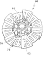
図5は、本発明の一実施例による洗濯機のベアリングハウジングを示す斜視図であり、図6は、図4におけるB部の詳細図であり、図7は、本発明の一実施例による洗濯機のステータ装着構造を示す分解断面図である。 5 is a perspective view showing a bearing housing of a washing machine according to an embodiment of the present invention, FIG. 6 is a detailed view of a portion B in FIG. 4, and FIG. 7 is a laundry according to an embodiment of the present invention. It is a disassembled sectional view which shows the stator mounting structure of a machine.
図3及び図5〜図7を参照すると、ベアリングハウジング60には、シャフト52が回転可能に支持される穴部61が形成される。穴部61は、ベアリングハウジング60の中央に形成され、シャフト52を収容する。穴部61の内壁には段部61aが形成され、ベアリング54はこの段部61aに設置される。
Referring to FIGS. 3 and 5 to 7, the bearing
ベアリングハウジング60には締付け部70が設けられる。締付け部70は、穴部61から所定間隔隔たって設けられ、タブ50の背壁部から露出されるように設けられたり突出するように設けられる。洗濯機の駆動中に発生する振動によりベアリングハウジング60が歪んだり破損することを防止するために、締付け部70の間にはリブ63が形成される。リブ63は、円周方向または半径方向に形成される。
The bearing
締付け部70は、締付け孔72を含み、ステータ67には締付け孔72に対応する位置に貫通孔部67aが形成される。ベアリングハウジング60とステータ67とは、締付け孔72及び貫通孔部67aに挿入される第1締付け部材76により結合される。一方、締付け孔72には、第1締付け部材76が結合するようにネジ山が形成される。
The tightening
一実施例として、締付け孔72の形成された部分72cは、締付け部70から突出して形成される。締付け孔72の形成された部分72cにステータ67が結合される。締付け孔72の形成された部分72cが突出して形成されているので、組立時に、他の部材との干渉なしにステータ67をベアリングハウジング60に結合することができる。
As an example, the
図示してはいないが、締付け孔72がタブ50の背壁部から露出されたり、締付け孔72の形成された部分72cがタブ50の背壁部から突出するように設けられることもできる。すなわち、締付け部70がタブ50にインサートされ、ステータ67が結合される締付け孔72や締付け孔72の形成された部分72cが、タブ50の背壁部から突出するように設けられることも可能である。
Although not shown, the tightening
ステータ67の内側には、締付け孔72の形成された部分72cに対応して係止突部67bが形成される。ステータ67とベアリングハウジング60との結合時に、係止突部67bの内側に、締付け孔72の形成された部分72cが嵌められるので、ステータ67はベアリングハウジング60の所望の位置に正確に結合される。本実施例で、ステータ67は別の部材を介在することなく金属材質のベアリングハウジング60に直接結合されるので、ステータ67を正確な位置に結合することができる。
On the inner side of the
また、ステータ67には、着座凹溝67cが形成される。ブラケット80とステータ67との組立を容易にするために、着座凹溝67cは、ブラケット80に対応するステータ67の背壁部に形成される。
In addition, a seating
ブラケット80は、ステータ67を支持し、ベアリングハウジング60側に加圧する役割を果たす。ブラケット80は、貫通孔部67aに対応する位置に形成される結合孔部82と、シャフト52が貫通する通過穴部86と、通過穴部86の縁部がタブ50の方向に傾くように形成されてなる傾斜部88と、を含む。ベアリングハウジング60の締付け部70に配置されたステータ67の着座凹溝67cにブラケット80を挿入した後、結合孔部82及び貫通孔部67aに第1締付け部材76を挿入して締付け孔72に結合することで、ステータ67及びブラケット80がベアリングハウジング60に結合される。この場合、第1締付け部材76がブラケット80をステータ67側に加圧し、ブラケット80はステータ67と複数の箇所で点接触、線接触または面接触することとなる。すなわち、第1締付け部材76が締め付けられる部位における圧力集中現象を防止するために、ブラケット80は、ステータ67と部分的または全体的に点接触、線接触または面接触して結合される。これにより、加圧力がステータ67に均一に伝達されるので、ステータ67をベアリングハウジング60に密着させることができる。第1締付け部材76による締付け力がブラケット80を通じて分散されつつステータ67を加圧するから、特定の箇所における圧力集中現象を防止することができ、かつ、ステータ67の同心度を維持することができる。また、ブラケット80によってベアリングハウジング60とステータ67との同心度が維持されるので、ステータ67とシャフト52に設置されるロータ69間の間隔も均一に維持することができる。
The
ブラケット80の傾斜部88は、ステータ67の内側方向に延突し、傾斜部88の中央に形成される通過穴部86にベアリングハウジング60の穴部61が挿入される。ブラケット80の内側80fは、タブ50の後端部50fにより支持される。ブラケット80の内側80fは、通過穴部86の周縁部が折り曲がって形成されることが好ましい。一実施例として、ブラケット80の内側80fは、タブ50の後端部50fの外周面に密着されるように形成される。このように、ブラケット80とタブ50とが接触して結合される場合、ブラケット80がタブ50の後端部50fにより支持され、かつ、シャフト52から発生する振動がブラケット80を通じて分散される。本実施例では、ブラケット80の内側80fがタブ50の後端部50fにより支持される例を説明したが、本発明は、これに限定されずに様々な変形実施が可能であり、例えば、ブラケット80の内側80fがベアリングハウジング60の後端部により支持される構成にしても良い。
The
ブラケット80には、ベアリングハウジング60で発生する熱を放出する一つ以上の冷却孔部84が形成される。洗濯機の駆動中に発生する熱は冷却孔部84から放出される。冷却孔部84は、結合孔部82と通過穴部86との間に形成されたり、または、傾斜部88に形成される。冷却孔部84は、ブラケット80の全体にわたって形成されることが好ましい。
The
上述の通り、本実施例では、一つの締付け部材76を用いてベアリングハウジング60、ステータ67、ブラケット80を結合する場合を例に上げて説明したが、本発明は、これに限定されず、締付け部材を用いて上記の3つの部材のうち2つずつをそれぞれ結合するなど、様々な変形実施が可能である。
As described above, in the present embodiment, the case where the bearing
次に、上記のように構成された本発明の一実施例による洗濯機の組立方法について説明する。 Next, a method for assembling a washing machine according to an embodiment of the present invention configured as described above will be described.
図8は、本発明の一実施例による洗濯機の組立方法を示すフローチャートである。 FIG. 8 is a flowchart illustrating a method of assembling a washing machine according to an embodiment of the present invention.
図8を参照すると、射出成形などの方法でベアリングハウジング60を製造する(S10)。その後、ベアリングハウジング60をジグ(図示せず)などを用いて支持した状態でタブ50をインサート射出成形する(S20)。この時、ベアリングハウジング60の締付け部70や締付け孔72がタブ50の外部に露出されるようにタブ50をインサート射出し、締付け部70や締付け孔72の形成された部分72cがタブ50の背壁部から突出するようにインサート射出することが好ましい。また、射出成形時に、ベアリングハウジング60は、ジグにより締付け部70や締付け孔72の形成された部分72cで支持されることが好ましい。このように、タブ50の内側にインサートされる部分以外の、外部に露出された締付け部70や締付け孔72の形成された部分72cがジグにより支持された状態でベアリングハウジング60がタブ50にインサートされるので、インサート作業を容易に行うことができ、生産性も向上し、ベアリングハウジング60を正確な位置にインサートさせることができる。
Referring to FIG. 8, the bearing
インサート射出作業が完了した後、ベアリングハウジング60の締付け部70にステータ67とブラケット80を配置した状態で、結合孔部82、貫通孔部67a及び締付け孔72に第1締付け部材76を結合することで、ステータ67及びブラケット80を結合させる(S30,S40,S50)。この時、金属材質からなるベアリングハウジング60、ステータ67及びブラケット80が互いに接触して支持されるので、各部材が安定して支持され、かつ、より効率的に同心度を維持することができる。
After the insert injection operation is completed, the first tightening
図9は、本発明の他の実施例による洗濯機のステータ装着構造を示す断面図であり、図10は、図9におけるC部の詳細図であり、図11は、本発明の他の実施例による洗濯機のステータ装着構造を示す分解断面図である。 9 is a sectional view showing a stator mounting structure of a washing machine according to another embodiment of the present invention, FIG. 10 is a detailed view of a portion C in FIG. 9, and FIG. 11 is another embodiment of the present invention. It is an exploded sectional view showing the stator mounting structure of the washing machine by the example.
説明の便宜のために、上記の実施例と実質的に同一の構成及び作用を有する構成要素には同一の参照番号を付し、その詳細な説明は省略する。 For convenience of explanation, the same reference numerals are given to components having substantially the same configuration and operation as the above embodiment, and detailed description thereof will be omitted.
図9〜図11を参照すると、本発明の他の実施例による洗濯機は、ステータ67とブラケット80とを結合させる結合部90を含む。結合部90は、ステータ67に形成される締付け穴部92と、締付け穴部92に対応する位置においてブラケット80に形成される補助結合部94と、を含む。本発明の他の実施例による洗濯機は、ベアリングハウジング60、ステータ67、ブラケット80を1回の作業で結合する上記の一実施例とは違い、少なくとも2回の作業で結合する。まず、ステータ67とブラケット80とを第2締付け部材96により結合する。その後、ステータ67とブラケット80とが結合された組立体を、第1締付け部材76を用いてベアリングハウジング60に結合する。すなわち、本発明の一実施例は一回の締付け作業で3つの部材、すなわち、ベアリングハウジング60、ステータ67及びブラケット80を同時に結合するのに対し、本発明の他の実施例は、ステータ67とブラケット80とが組み立てられた状態でこの組立体とベアリングハウジング60とを結合するので、組立性が向上する。したがって、本発明の他の実施例は、モーター65を容易に組み立てることができ、組立作業にかかる時間や費用を節減することができる。
9 to 11, the washing machine according to another embodiment of the present invention includes a
図12は、本発明の他の実施例による洗濯機の組立方法を示すフローチャートである。 FIG. 12 is a flowchart illustrating a method of assembling a washing machine according to another embodiment of the present invention.
図12を参照すると、射出成形などの方法でベアリングハウジング60を製造する(S100)。その後、ベアリングハウジング60をジグ(図示せず)などを用いて支持した状態でタブ50をインサート射出成形する(S200)。この時、ベアリングハウジング60の締付け部70や締付け孔72がタブ50の外部に露出されるようにタブ50をインサート射出し、締付け部70や締付け孔72の形成された部分72cがタブ50の背壁部から突出するようにインサート射出することが好ましい。また、射出成形時に、ベアリングハウジング60はジグにより締付け部70や締付け孔72の形成された部分72cで支持されることが好ましい。このように、タブ50の内側にインサートされる部分以外の、外部に露出された締付け部70や締付け孔72の形成された部分72cがジグにより支持された状態でベアリングハウジング60がタブ50にインサートされるので、インサート作業を容易に行うことができ、生産性も向上し、ベアリングハウジング60を正確な位置にインサートさせることができる。
Referring to FIG. 12, the bearing
インサート射出作業が完了した後、ステータ67とブラケット80とをまず結合する(S300)。その後、結合されたステータ67とブラケット80との組立体を締付け部70や締付け孔72に位置させた後(S400)、該組立体を締付け部材を用いて締付け部70や締付け孔72に締め付ける(S500)。
After the insert injection operation is completed, the
以上では図面に基づく実施例に挙げて本発明を説明してきたが、これらの実施例は例示的なものに過ぎず、当該技術分野における通常の知識を有する者には、本発明の範囲内で様々な変形実施が可能であるということが理解できる。また、以上ではドラム洗濯機を例にして説明したが、このドラム洗濯機に限定されず、他の洗濯機にも本発明を適用することができる。したがって、本発明の真の技術的保護範囲は、添付の特許請求の範囲により定められるべきである。 Although the present invention has been described with reference to the embodiments based on the drawings, these embodiments are merely illustrative, and those having ordinary knowledge in the technical field are within the scope of the present invention. It can be understood that various modifications can be made. Further, the drum washing machine has been described above as an example. However, the present invention is not limited to this drum washing machine, and the present invention can be applied to other washing machines. Accordingly, the true technical protection scope of the present invention should be determined by the appended claims.
Claims (10)
前記タブの外部に締付け部が露出されるように前記タブにインサート射出されるベアリングハウジングと、
前記締付け部に結合されるステータと、
前記ステータを支持し、前記ベアリングハウジングに向けて前記ステータを加圧するように配置されるブラケットと、
を含み、
前記締付け部は、前記タブの背壁部から突出するように設けられており、
前記ブラケットは、
前記ステータに形成された貫通孔部に対応する位置に形成される結合孔部と、
シャフトが貫通する通過穴部と、
前記通過穴部の周縁部が前記タブ方向に傾くように形成される傾斜部と、
を含むことを特徴とする洗濯機。Tabs,
A bearing housing that is insert-injected into the tab such that a tightening portion is exposed to the outside of the tab;
A stator coupled to the tightening portion;
A bracket arranged to support the stator and pressurize the stator toward the bearing housing;
Including
The tightening portion is provided so as to protrude from the back wall portion of the tab,
The bracket is
A coupling hole formed at a position corresponding to the through hole formed in the stator;
A passage hole through which the shaft passes,
An inclined portion formed so that a peripheral edge portion of the passage hole portion is inclined in the tab direction;
A washing machine comprising:
前記ステータに形成される締付け穴部と、
前記締付け穴部に対応する位置において前記ブラケットに形成される補助結合部と、
を含むことを特徴とする、請求項9に記載の洗濯機。The coupling portion is
A tightening hole formed in the stator;
An auxiliary coupling portion formed on the bracket at a position corresponding to the tightening hole portion;
The washing machine according to claim 9 , comprising:
Applications Claiming Priority (7)
| Application Number | Priority Date | Filing Date | Title |
|---|---|---|---|
| KR1020070112004A KR101297996B1 (en) | 2007-11-05 | 2007-11-05 | Washing machine and assembling method thereof |
| KR1020070112006A KR20090046069A (en) | 2007-11-05 | 2007-11-05 | Washing machine and assembling method thereof |
| KR1020070112005A KR101297997B1 (en) | 2007-11-05 | 2007-11-05 | Washing machine and assembling method thereof |
| KR10-2007-0112006 | 2007-11-05 | ||
| KR10-2007-0112005 | 2007-11-05 | ||
| KR10-2007-0112004 | 2007-11-05 | ||
| PCT/KR2008/005849 WO2009061080A1 (en) | 2007-11-05 | 2008-10-06 | Washing machine and assembling method thereof |
Publications (2)
| Publication Number | Publication Date |
|---|---|
| JP2011502622A JP2011502622A (en) | 2011-01-27 |
| JP5033242B2 true JP5033242B2 (en) | 2012-09-26 |
Family
ID=40586758
Family Applications (1)
| Application Number | Title | Priority Date | Filing Date |
|---|---|---|---|
| JP2010532991A Expired - Fee Related JP5033242B2 (en) | 2007-11-05 | 2008-10-06 | Washing machine |
Country Status (5)
| Country | Link |
|---|---|
| US (1) | US20090113941A1 (en) |
| EP (1) | EP2217753A4 (en) |
| JP (1) | JP5033242B2 (en) |
| CN (1) | CN101849060B (en) |
| WO (1) | WO2009061080A1 (en) |
Families Citing this family (11)
| Publication number | Priority date | Publication date | Assignee | Title |
|---|---|---|---|---|
| KR20100085379A (en) * | 2009-01-20 | 2010-07-29 | 삼성전자주식회사 | Bearing housing, water tub for washing machine and manufacturing mold for the same |
| EP2459791B1 (en) * | 2009-07-31 | 2023-08-30 | LG Electronics Inc. | A fabric treating machine |
| DE102009044574B3 (en) * | 2009-11-18 | 2011-02-17 | Miele & Cie. Kg | Plastic container for a washing machine |
| IT1398582B1 (en) * | 2010-03-09 | 2013-03-01 | Skf Ab | CANNOTTO COSTAMPABILE WITH WASHING MACHINE TANKS |
| EP2392719A1 (en) * | 2010-06-01 | 2011-12-07 | Electrolux Home Products Corporation N.V. | Assembly method and assembly apparatus for assembly the washing group of a laundry washing machine |
| ITTO20130744A1 (en) * | 2013-09-13 | 2015-03-14 | Skf Ab | CANNOTTO COSTAMPABILE WITH WASHING MACHINE TANKS |
| KR20160038241A (en) * | 2014-09-30 | 2016-04-07 | 동부대우전자 주식회사 | Washing machine with tub and manufacturing method the same |
| KR102252508B1 (en) * | 2015-01-05 | 2021-05-14 | 엘지전자 주식회사 | laundry machine |
| US10975513B2 (en) | 2017-03-23 | 2021-04-13 | Midea Group Co., Ltd. | Tub with bearing housing insert for a laundry washing machine |
| US10487435B2 (en) | 2017-03-23 | 2019-11-26 | Midea Group Co., Ltd. | Tub for a laundry washing machine |
| CN109167457A (en) * | 2018-10-17 | 2019-01-08 | 珠海凯邦电机制造有限公司 | A kind of end cover for motor and the washing machine with it |
Family Cites Families (15)
| Publication number | Priority date | Publication date | Assignee | Title |
|---|---|---|---|---|
| KR100245291B1 (en) * | 1997-10-27 | 2000-02-15 | 구자홍 | A bearing housing of the direct connecting type washing machine |
| DE19755537A1 (en) * | 1997-12-13 | 1999-06-17 | Fhp Motors Gmbh | Transport safety mechanism for assembled and justified motor kit brushless DC motor, e.g for washing machines |
| DE19960501A1 (en) * | 1999-12-15 | 2001-06-21 | Bsh Bosch Siemens Hausgeraete | Suds container for a washing machine |
| DE10056986A1 (en) * | 2000-11-17 | 2002-05-23 | Bsh Bosch Siemens Hausgeraete | Fitting or removing drive elements in domestic machine involves fitting extension adapter part to free end of shaft, carrying out fitting and removal of drive elements using adapter part |
| DE10060940A1 (en) * | 2000-12-07 | 2002-06-13 | Bsh Bosch Siemens Hausgeraete | Motor has protrusion on stator bearer part to form guiding engagement with aperture near bearer star for assembly with approximate positioning with respect to center axis |
| KR100651980B1 (en) * | 2003-12-02 | 2006-11-30 | 엘지전자 주식회사 | structure of driving unit of drum-type washing machine |
| DE60320873D1 (en) * | 2002-12-10 | 2008-06-19 | Lg Electronics Inc | drum washing machine |
| KR100595192B1 (en) * | 2003-11-06 | 2006-06-30 | 엘지전자 주식회사 | structure of driving unit in drum-type washing machine |
| DE102004049549A1 (en) * | 2004-03-24 | 2005-10-13 | Diehl Ako Stiftung & Co. Kg | Motor as direct drive and method of mounting the motor |
| KR101022222B1 (en) * | 2004-11-17 | 2011-03-17 | 삼성전자주식회사 | Washing machine |
| KR101227483B1 (en) * | 2005-11-09 | 2013-01-29 | 엘지전자 주식회사 | motor for direct drive type washing machine and method for fabricating the same |
| KR100720581B1 (en) * | 2005-11-21 | 2007-05-22 | 엘지전자 주식회사 | Washing machine |
| EP2052104B1 (en) * | 2006-07-20 | 2013-01-30 | LG Electronics Inc. | Drum type laundry machine |
| KR20070004508A (en) * | 2006-12-20 | 2007-01-09 | 주식회사 대우일렉트로닉스 | Washing machine |
| DE102007030508B4 (en) * | 2007-06-30 | 2014-10-16 | Schaeffler Technologies Gmbh & Co. Kg | Washing machines direct drive |
-
2008
- 2008-10-06 CN CN2008801146982A patent/CN101849060B/en not_active Expired - Fee Related
- 2008-10-06 JP JP2010532991A patent/JP5033242B2/en not_active Expired - Fee Related
- 2008-10-06 WO PCT/KR2008/005849 patent/WO2009061080A1/en active Application Filing
- 2008-10-06 EP EP08846286A patent/EP2217753A4/en not_active Withdrawn
- 2008-10-30 US US12/261,236 patent/US20090113941A1/en not_active Abandoned
Also Published As
| Publication number | Publication date |
|---|---|
| WO2009061080A1 (en) | 2009-05-14 |
| CN101849060B (en) | 2012-09-05 |
| US20090113941A1 (en) | 2009-05-07 |
| EP2217753A1 (en) | 2010-08-18 |
| CN101849060A (en) | 2010-09-29 |
| JP2011502622A (en) | 2011-01-27 |
| EP2217753A4 (en) | 2012-02-22 |
Similar Documents
| Publication | Publication Date | Title |
|---|---|---|
| JP5033242B2 (en) | Washing machine | |
| US7114355B2 (en) | Drum type washing machine having a driving unit | |
| US7441421B2 (en) | Drum type washing machine | |
| US20090064726A1 (en) | Driving apparatus for washing machine | |
| KR101297996B1 (en) | Washing machine and assembling method thereof | |
| US20080122305A1 (en) | Direct Drive Motor in Washing Machine | |
| US8256247B2 (en) | Washing machine and manufacturing method thereof | |
| JP4938856B2 (en) | Drum washing machine | |
| KR101297997B1 (en) | Washing machine and assembling method thereof | |
| KR101319852B1 (en) | Washing machine | |
| KR20090046069A (en) | Washing machine and assembling method thereof | |
| EP1439254A2 (en) | Structure of driving unit in drum type washing machine | |
| KR101297993B1 (en) | Washing machine | |
| KR20110032959A (en) | Drum type washing machine |
Legal Events
| Date | Code | Title | Description |
|---|---|---|---|
| RD04 | Notification of resignation of power of attorney |
Free format text: JAPANESE INTERMEDIATE CODE: A7424 Effective date: 20111115 |
|
| A977 | Report on retrieval |
Free format text: JAPANESE INTERMEDIATE CODE: A971007 Effective date: 20111129 |
|
| A131 | Notification of reasons for refusal |
Free format text: JAPANESE INTERMEDIATE CODE: A131 Effective date: 20111206 |
|
| A521 | Written amendment |
Free format text: JAPANESE INTERMEDIATE CODE: A523 Effective date: 20120306 |
|
| TRDD | Decision of grant or rejection written | ||
| A01 | Written decision to grant a patent or to grant a registration (utility model) |
Free format text: JAPANESE INTERMEDIATE CODE: A01 Effective date: 20120626 |
|
| A01 | Written decision to grant a patent or to grant a registration (utility model) |
Free format text: JAPANESE INTERMEDIATE CODE: A01 |
|
| A61 | First payment of annual fees (during grant procedure) |
Free format text: JAPANESE INTERMEDIATE CODE: A61 Effective date: 20120629 |
|
| R150 | Certificate of patent or registration of utility model |
Ref document number: 5033242 Country of ref document: JP Free format text: JAPANESE INTERMEDIATE CODE: R150 Free format text: JAPANESE INTERMEDIATE CODE: R150 |
|
| FPAY | Renewal fee payment (event date is renewal date of database) |
Free format text: PAYMENT UNTIL: 20150706 Year of fee payment: 3 |
|
| R250 | Receipt of annual fees |
Free format text: JAPANESE INTERMEDIATE CODE: R250 |
|
| R250 | Receipt of annual fees |
Free format text: JAPANESE INTERMEDIATE CODE: R250 |
|
| R250 | Receipt of annual fees |
Free format text: JAPANESE INTERMEDIATE CODE: R250 |
|
| R250 | Receipt of annual fees |
Free format text: JAPANESE INTERMEDIATE CODE: R250 |
|
| R250 | Receipt of annual fees |
Free format text: JAPANESE INTERMEDIATE CODE: R250 |
|
| LAPS | Cancellation because of no payment of annual fees |