JP5023508B2 - Wireless positioning system, wireless positioning method, and program for wireless positioning - Google Patents
Wireless positioning system, wireless positioning method, and program for wireless positioning Download PDFInfo
- Publication number
- JP5023508B2 JP5023508B2 JP2006042633A JP2006042633A JP5023508B2 JP 5023508 B2 JP5023508 B2 JP 5023508B2 JP 2006042633 A JP2006042633 A JP 2006042633A JP 2006042633 A JP2006042633 A JP 2006042633A JP 5023508 B2 JP5023508 B2 JP 5023508B2
- Authority
- JP
- Japan
- Prior art keywords
- base station
- time
- mobile terminal
- pulse
- positioning
- Prior art date
- Legal status (The legal status is an assumption and is not a legal conclusion. Google has not performed a legal analysis and makes no representation as to the accuracy of the status listed.)
- Expired - Fee Related
Links
Images


Description
本発明は、無線測位システム、無線測位方法および無線測位のためのプログラムに関し、特に移動端末の位置検出に用いて好適な無線測位システム、無線測位方法および無線測位のためのプログラムに関する。
The present invention relates to a radio positioning system, a radio positioning method, and a program for radio positioning, and more particularly, to a radio positioning system , a radio positioning method, and a program for radio positioning suitable for use in detecting the position of a mobile terminal.
移動端末の位置を検出する測位方式として、GPS(Global Positioning System:全地球測位システム)のように、複数の基地局(衛星)から送信した電波が移動端末までに到達する時間差(以下TDOA:Time Difference of Arrival)を用いる方式がある。 As a positioning method for detecting the position of a mobile terminal, a time difference (hereinafter referred to as TDOA: Time) in which radio waves transmitted from a plurality of base stations (satellites) reach the mobile terminal, such as GPS (Global Positioning System). There is a method using the Difference of Arrival).
図1に、TDOAの原理図を示す。図1において、101は基地局A、102は基地局B、103は基地局C、104は基地局D、105は移動端末M、106は双曲線、107は双曲線をそれぞれ示す。移動端末M105から基地局A101、基地局B102、基地局C103までのそれぞれの距離をra、rb、rcとする。距離差(ra−rb)が求まると、基地局A101と基地局B102を焦点とした双曲線106が描ける。同様に、距離差(ra−rc)が求まると、基地局A101と基地局C103を焦点とした双曲線107が描ける。前記2つの双曲線106、107の交点が移動端末M105となる。前記の距離ra、rb、rcは、移動端末M105から同時に送信された電波が、基地局A101、基地局B102、基地局C103で受信された時刻を用いて、各距離を伝播した電波の遅延時間が求まる。移動端末M105から基地局A101までと、移動端末M105から基地局B102までの遅延時間の差により、距離差(ra−rb)が求まり、移動端末M105から基地局A101までと、移動端末M105ら基地局C103までの遅延時間の差により、距離差(ra−rc)が求まる。
FIG. 1 shows a principle diagram of TDOA. In FIG. 1, 101 is a base station A, 102 is a base station B, 103 is a base station C, 104 is a base station D, 105 is a mobile terminal M, 106 is a hyperbola, and 107 is a hyperbola. The distances from the mobile terminal M105 to the base station A101, base station B102, and base station C103 are denoted by r a , r b , and rc, respectively. When the distance difference (r a −r b ) is obtained, a
前記のTDOA方式により移動端末M105の位置検出を行うには、複数の基地局から
電波を発信するタイミングが一致または固定であれば、移動端末側で到達時間差を求めることができる。そのためには、各基地局が時間同期している必要がある。
In order to detect the position of the mobile terminal M105 by the TDOA method, the arrival time difference can be obtained on the mobile terminal side if the timing of transmitting radio waves from a plurality of base stations coincides or is fixed. For that purpose, each base station needs to be time-synchronized.
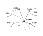
GPSでは、各衛星に原子時計を搭載しているため時間のずれは小さいが、各衛星の原子時計が同期していないため、少しずつずれる。そこで、図2に示す方法が採られる。 In GPS, since the atomic clock is mounted on each satellite, the time lag is small, but since the atomic clocks of the satellites are not synchronized, they are shifted little by little. Therefore, the method shown in FIG. 2 is adopted.
図2において、201は衛星A、202は衛星B、203は衛星C、204は地上制御局、205は地上移動端末をそれぞれ示し、<1>はGPS信号受信、<2>は衛星時計補正値計算、<3>は補正値衛星送信、<4>は補正値データ送信のステップをそれぞれ示す。 In FIG. 2, 201 is a satellite A, 202 is a satellite B, 203 is a satellite C, 204 is a ground control station, 205 is a ground mobile terminal, <1> is a GPS signal reception, and <2> is a satellite clock correction value. Calculation, <3> indicates a step of transmitting correction value satellite, and <4> indicates a step of transmitting correction value data.
地上制御局205はステップ<1>によりGPS信号を受信して、ステップ<2>により各衛星の時計の補正計算を行い、各衛星の時計のずれを監視し、ステップ<3>により各衛星に補正値を送り、ステップ<4>により各衛星から時間補正情報を航法メッセージに乗せて、移動端末205に送信する同期方法が用いられる。
The
また、従来技術として、移動端末(携帯電話)の測位を行う目的で、各基地局内や、基地局間のケーブル遅延を補正するための疑似基地局を設け、GPS信号を用いて同期用クロックを生成し、該クロックにより各基地局の時間を同期させている(特許文献1参照)。 In addition, as a conventional technique, for the purpose of positioning a mobile terminal (mobile phone), a pseudo base station for correcting cable delays in each base station and between base stations is provided, and a synchronization clock is generated using a GPS signal. The time of each base station is synchronized with the generated clock (see Patent Document 1).
また、各基地局を有線あるいは無線で接続して各基地局のクロックを同期させる方法がある(特許文献2参照)。しかし、有線で接続するのは、ケーブル敷設の手間がかかり、コスト高になる。 In addition, there is a method in which the base stations are connected by wire or wireless to synchronize the clocks of the base stations (see Patent Document 2). However, the wired connection requires time and labor for laying the cable, resulting in high costs.
また、無線でクロックを同期させるためには、無線信号からクロックを抽出して、自局のクロックを同期させる必要があり、回路が複雑となる。また、常時、無線により同期信号を送るため、同期信号専用の無線チャンネルが必要となっていた。
前記のGPSに相当する電波測位システムを地上で構築する場合、前記GPSと同じ時間同期方式を使用すると、制御局と各基地局とで、本来不要な専用通信路が必要であり、制御局が全ての基地局の時計のずれを管理するため、制御局の動作が複雑になり、基地局が多いと制御局の制御が、各移動端末の測位周期に間に合わなくなる。 When a radio positioning system corresponding to the GPS is constructed on the ground, if the same time synchronization method as that of the GPS is used, a dedicated communication channel that is originally unnecessary is required between the control station and each base station. Since the clock deviation of all the base stations is managed, the operation of the control station becomes complicated, and if there are many base stations, the control of the control station will not be in time for the positioning cycle of each mobile terminal.
また、GPS信号を用いて同期用クロックを生成し、各基地局を同期させる方法は、GPS信号からの同期用クロック精度は数10nsec程度であり、1m以下の精度が必要な場合は、1nsec程度の時間精度が必要となり、GPS信号からのクロックでは前記1m以下の精度は実現出来ない。 In addition, a method of generating a synchronization clock using a GPS signal and synchronizing each base station has a synchronization clock accuracy of about several tens of nsec from the GPS signal, and about 1 nsec when accuracy of 1 m or less is required. Therefore, the accuracy of 1 m or less cannot be realized with the clock from the GPS signal.
また、時間精度を上げるために、GPSに相当する安定な同期信号を生成し、各基地局に送信し同様なシステムを構成しようとしても、同期用の信号伝送と測位用の信号伝送に異なる電波が必要となり、システムが複雑でコスト高となる。 In addition, in order to improve time accuracy, a stable synchronization signal equivalent to GPS is generated and transmitted to each base station to form a similar system. However, different radio waves are used for synchronization signal transmission and positioning signal transmission. Is required, and the system is complicated and expensive.
従って、本発明の目的の1つは移動端末の位置を正確に検出する無線測位装置、無線測位方法および無線測位のためのプログラムを提供することである。 Accordingly, one of the objects of the present invention is to provide a radio positioning apparatus, a radio positioning method, and a program for radio positioning that accurately detect the position of a mobile terminal.
尚、上記目的に限らず、後述する発明を実施するための最良の形態に示す各構成により導かれる結果であって、従来の技術によっては得られない効果を奏することも、本発明の他の目的の1つとして位置付けることができる。 The present invention is not limited to the above-mentioned object, and is a result derived from each configuration shown in the best mode for carrying out the invention described later, and has an effect that cannot be obtained by conventional techniques. It can be positioned as one of the purposes.
(1)本発明では、
少なくも3つの基地局から測位信号パルスを送信して、移動端末の位置座標を決定する無線測位システムであって、
前記基地局は、1つの主基地局と複数の従基地局を含み、
前記主基地局は、
同期信号パルスを前記従基地局に送信する送信手段と、
前記同期信号パルスの送信時刻に所定の時間を加えた時刻に、前記移動端末に第1測位信号パルスを送信する手段とを備え、
前記従基地局は、
前記同期信号パルスの受信時刻の決定を、前記従基地局が備えた基準クロックを基準として、前記基準クロックで動作する粗タイマーと、前記基準クロックよりも細かい刻みで動作する精密タイマーを用いて行い、
前記主基地局から送信された同期信号パルスの受信時刻と前記従基地局の前記基準クロックとの間のずれ時間T fb を測定する手段と、
前記ずれ時間T fb と、予め設定された遅延時間T pb とから前記主基地局の基準クロックと前記従基地局の基準クロックとの間のクロックのずれ時間T ob を求める手段と、
前記主基地局の前記第1測位信号の送信時刻に前記クロックのずれ時間T ob を加えた時刻に、第2測位信号パルス及び前記クロックのずれ時間T ob を前記移動端末に送信する手段とを備え、
前記移動端末は、
前記第2測位信号パルスを受信した時刻を前記クロックのずれ時間T ob を用いて補正
する手段と、
前記第1測位信号パルスを受信した時刻および前記補正後の第2測位信号パルスを受信した時刻と、前記移動端末に保存した前記主基地局と前記従基地局の位置座標とを用いて、前記移動端末の位置座標を決定する手段と、
を備えたことを特徴とする無線測位システムを用いる。
(1) In the present invention,
A radio positioning system that determines the position coordinates of a mobile terminal by transmitting positioning signal pulses from at least three base stations,
The base station includes one master base station and a plurality of slave base stations,
The main base station is
Transmitting means for transmitting a synchronization signal pulse to the slave base station ;
Means for transmitting a first positioning signal pulse to the mobile terminal at a time obtained by adding a predetermined time to the transmission time of the synchronization signal pulse;
The slave base station is
The determination of the reception time of the synchronizing signal pulses, with reference to the reference clock, wherein the slave base station is provided, a crude timer operates at the reference clock is performed with a precision timer operating in finer increments than the reference clock ,
Means for measuring a time difference T fb between the reception time of the synchronization signal pulse transmitted from the master base station and the reference clock of the slave base station;
Means for obtaining a clock shift time Tob between a reference clock of the master base station and a reference clock of the slave base station from the shift time T fb and a preset delay time T pb ;
The time obtained by adding the delay times T ob of the clock to the transmission time of the first positioning signal of the main base station, and means for transmitting the second positioning signal pulse and shift time T ob of the clock to the mobile terminal Prepared,
The mobile terminal
Means for correcting using the shift time T ob of said time of receiving said second positioning signal pulse clock,
Using the time when the first positioning signal pulse is received and the time when the corrected second positioning signal pulse is received, and the position coordinates of the master base station and the slave base station stored in the mobile terminal, Means for determining the position coordinates of the mobile terminal;
A wireless positioning system characterized by comprising:
好ましくは、前記基地局は、前記移動端末への前記第1測位信号パルスの送信を、所定の周期で繰り返す手段を備えたことを特徴とする請求項1記載の無線測位システムを用いる。
Preferably, the base station, the transmission of the first positioning signal pulse to said mobile terminal, using a radio positioning system according to
好ましくは、前記基地局は、前記移動端末に送信する前記第1測位信号パルスを、前記主基地局と前記従基地局からの前記第2測位信号パルスが前記移動端末において時間的に重ならない時間差をつけた所定の時刻に送信する手段と、前記時間的に重ならない時間差のデータを前記移動端末に送信する手段と、を備えたことを特徴とする請求項1記載の無線測位システムを用いる。
Good Mashiku, said base station, said first positioning signal pulse to be transmitted to the mobile terminal, temporally in the second positioning signal pulses the mobile terminal from the main base station and the subordinate base station heavy The wireless positioning system according to
好ましくは、前記基地局は、前記時間的に重ならない時間差で行なう測位信号パルスの送信と、前記時間差のデータの送信を、所定の周期で繰りかえす手段を備えたことを特徴とする請求項1記載の無線測位システムを用いる。
Preferably, the base station, the transmission of the positioning signal pulses carried by temporally non-overlapping time difference, the transmission of data of said time difference, according to
好ましくは、前記従基地局は、前記時間的に重ならない時間差をつけて前記第2測位信号パルスを送信する時刻の決定を、前記従基地局が備えた前記基準クロックを基準として、前記基準クロックで動作する前記粗タイマーと、前記基準クロックよりも細かい刻みで動作する前記精密タイマーを用いて行なうことを特徴とする請求項1記載の無線測位システムを用いる。
Preferably, the slave base station, the determination of the time for transmitting the second positioning signal pulses with a time difference that does not overlap with the time, based on said reference clock said slave base station with the reference clock in said coarse timer operates, the radio positioning system according to
好ましくは、前記主基地局は、前記同期信号パルスの機能を備えた前記第1測位信号パルスを送信する手段を備えたことを特徴とする請求項1記載の無線測位システムを用いる。
2. The radio positioning system according to
好ましくは、前記主基地局は、前記同期信号パルスの機能を備えた前記第1測位信号パルスの前記移動端末への送信を、所定の周期で繰り返す手段を備えたことを特徴とする請求項1記載の無線測位システムを用いる。
Preferably, the main base station, according to
好ましくは、前記基地局は、所定の擬似ランダムディジタル信号が、任意のディジタル信号によりパルス位置変調される手段と、前記パルス位置変調された擬似ランダムディジタル信号のチップ幅の特定位置でインパルス化した超広帯域無線信号を生成する手段と、前記インパルス化した超広帯域無線信号により、前記同期の機能を備えた測位信号パルスを送信する手段と、を備えたことを特徴とする請求項1記載の無線測位システムを用いる。
Preferably, the base station, a predetermined pseudo-random digital signal, and impulse-at a particular position of the device and the pulse position modulated chip width of the pseudorandom digital signal pulse position modulation by any
好ましくは、前記従基地局は、前記主基地局から受信した、前記同期の機能を備えた前記第2測位信号パルスの受信時刻の決定を、前記従基地局が備えた前記基準クロックを基準として、前記基準クロックで動作する前記粗タイマーと、前記基準クロックよりも細かい刻みで動作する前記精密タイマーを用いて行うことを特徴とする請求項1記載の無線測位システムを用いる。
Preferably, the slave base station received from the main base station, the determination of the reception time of having the synchronization function the second positioning signal pulse, based on said reference clock said slave base station with , using the rough timer and a radio positioning system according to
(2)また、前記基地局は、インパルス化された超広帯域無線信号を送信することを特徴
とする請求項1記載の無線測位システムを用いる。
(2) In addition, the base station uses the wireless positioning system according to
好ましくは、前記基地局は、所定の擬似ランダムディジタル信号が、任意のディジタル信号によりパルス位置変調され、該パルス位置変調された擬似ランダムディジタル信号のチップ幅の特定位置でインパルス化された信号を送信することを特徴とする請求項1記載の無線測位システムを用いる。
Preferably, the base station transmits a predetermined pseudo-random digital signal is pulse position modulated by any of the digital signal, the impulse signal at a particular position of the tip width of the pulse position modulated pseudo-random digital signal The wireless positioning system according to
好ましくは、前記基地局は、生成する擬似ランダムディジタル信号として、リードソロモン符号によりパルス位置変調された信号を用いることを特徴とする請求項1記載の無線測位システムを用いる。
Preferably, the base station, as a pseudo-random digital signal for generating, using a radio positioning system according to
好ましくは、前記基地局は、送信するインパルス化された信号を所定の帯域通過濾波器で帯域制限する手段を備えたことを特徴とする請求項1記載の無線測位システムを用いる。
Preferably, the base station uses a radio positioning system according to
好ましくは、前記従基地局は、前記同期信号パルスの受信時刻の決定を、前記従基地局が受信し検出した信号と、前記従基地局が備えた前記主基地局と同じ擬似ランダムディジタル信号との相関による時間比較により行う手段を備えたことを特徴とする請求項1記載の無線測位システム基地局を用いる。
(3)また、前記移動端末は、前記従基地局から受信した前記クロックのずれ時間T ob を用いて、前記第1、第2測位信号パルスを受信した時刻を補正する手段を備えたことを特徴とする請求項1記載の無線測位システムを用いる。
好ましくは、前記移動端末は、前記移動端末で決定された前記移動端末の位置座標を、識別された特定の他の移動端末のユーザに、前記基地局の少なくも1つを介して伝える手段と、識別された特定の固定端末のユーザに、前記基地局に接続されたネットワークを介して伝える手段と、を備えたことを特徴とする請求項1記載の無線測位システムを用いる
。
Preferably, the slave base station, the determination of the reception time of the sync pulse, and the signal in which the slave base station detects received, the same pseudo-random digital signal and the main base station the slave base station is provided with The wireless positioning system base station according to
(3) Further, the mobile terminal uses the time offset T ob of the clock received from the slave base station, further comprising: a first means for compensation a time of receiving the second positioning signal pulse the use of radio positioning system according to
Preferably, the mobile terminal, the position coordinates of the mobile terminal determined by the mobile terminal, the user of certain other mobile terminals identified, and means for transmitting through even one less of the base station The wireless positioning system according to
好ましくは、前記移動端末は、前記主基地局と前記従基地局からの前記第1、第2測位信号パルスの受信時刻の決定を、前記移動端末が受信し検出した信号と、前記移動端末に備えた前記主基地局と前記従基地局に固有の擬似ランダムディジタル信号との相関による時間比較により行う手段を備えたことを特徴とする請求項1記載の無線測位システムを用いる。
Preferably, the mobile terminal, the first from the slave base station and the main base station, the determination of the reception time of the second positioning signal pulse, a signal which the mobile terminal has detected received, to the
好ましくは、前記移動端末は、前記時間的に重ならない時間差のデータを用いて、前記移動端末で決定された前記移動端末の位置座標を、識別された特定の他の移動端末のユーザに、前記基地局の少なくも1つを介して伝える手段と、識別された特定の固定端末のユーザに、前記基地局に接続されたネットワークを介して伝える手段と、を備えたことを特徴とする請求項1記載の無線測位システムを用いる。
Preferably, the mobile terminal, using the data of the time difference does not overlap with the time, the position coordinates of the mobile terminal determined by the mobile terminal, the user of certain other mobile terminals identified, the claim that the means for transmitting the base station at least through one, characterized in that the user of a particular fixed terminal identified and and means for transmitting via a network connected to the
好ましくは、前記移動端末は、前記基地局から受信した前記移動端末において時間的に重ならない時間差のデータを用いて、前記基地局から測位信号パルスを受信した時刻を、所定の周期で補正する手段を備えたことを特徴とする請求項1記載の無線測位システムを用いる。
Preferably, the mobile terminal uses the data of the temporally non-overlapping time difference at said mobile terminal received from the base station, the time of reception of the positioning signal pulse from the base station, means for correcting a predetermined cycle The wireless positioning system according to
好ましくは、前記移動端末は、前記基地局から前記時間差で送信された前記第1、第2測位信号パルスの受信時刻の決定を、前記移動端末が受信し検出した信号と、前記移動端末に備えた前記各基地局に共通の擬似ランダムディジタル信号との相関による時間比較により行う手段と、前記測位信号パルスの受信時刻を、前記前記基地局から受信した時間差のデータで補正する手段とを備えたことを特徴とする請求項1記載の無線測位システムを用いる。
Preferably, the mobile terminal, the first sent by the time difference from the base station, the determination of the reception time of the second positioning signal pulse, a signal which the mobile terminal has detected received, provided to the mobile terminal And means for performing time comparison by correlation with a pseudo-random digital signal common to each base station, and means for correcting the reception time of the positioning signal pulse with time difference data received from the base station. The wireless positioning system according to
好ましくは、前記移動端末は、前記同期信号パルスの機能を備えた前記第1、第2測位信号パルスの受信時刻を用いて決定された前記移動端末の位置座標を、識別された特定の他の移動端末のユーザに、前記基地局の少なくも1つを介して伝える手段と、識別された特定の固定端末のユーザに、前記基地局に接続されたネットワークを介して伝える手段と、を備えたことを特徴とする請求項1記載の無線測位システムを用いる
好ましくは、前記移動端末は、前記同期信号パルスの機能を備えた前記第1、第2測位信号パルスを受信した時刻を、前記基地局から受信した時間差のデータを用いて、所定の周期で補正する手段を備えたことを特徴とする請求項1記載の無線測位システムを用いる。
Preferably, the mobile terminal, the first having the function of the sync pulse, the position coordinates of the second positioning signal pulse the mobile terminal which is determined using the reception time of the identified specific other was Means for communicating to a user of a mobile terminal via at least one of the base stations, and means for communicating to a user of a specific identified fixed terminal via a network connected to the base station. preferably using wireless positioning system of
好ましくは、前記移動端末は、前記基地局から受信した前記同期信号パルスの機能を備えた前記第1、第2測位信号パルスの受信時刻の決定を、前記移動端末が受信し検出した信号と、前記移動端末に備えた前記基地局に共通の擬似ランダムディジタル信号との相関による時間比較により行うことを特徴とする請求項1記載の無線測位システムを用いる。(4)本発明では、少なくも3つの基地局から測位信号パルスを送信して、移動端末の位置座標を決定する無線測位方法であって、前記基地局は、1つの主基地局と複数の従基地局を含み、前記主基地局が、同期信号パルスを前記従基地局に送信するステップと、前記同期信号パルスの送信時刻に所定の時間を加えた時刻に、前記移動端末に第1測位信号パルスを送信するステップと、前記従基地局が、前記同期信号パルスの受信時刻の決定を、前記従基地局が備えた基準クロックを基準として、前記基準クロックで動作する粗タイマーと、前記基準クロックよりも細かい刻みで動作する精密タイマーを用いて行うステップと、前記主基地局から送信された同期信号パルスの受信時刻と前記従基地局の前記基準クロックとの間のずれ時間T fb を測定するステップと、前記ずれ時間T fb と、予め設定された遅延時間T pb とから前記主基地局の基準クロックと前記従基地局の基準クロックとの間のクロックのずれ時間T ob を求めるステップと、前記主基地局の前記第1測位信号の送信時刻に前記クロックのずれ時間T ob を加えた時刻に、第2測位信号パルス及び前記クロックのずれ時間T ob を前記移動端末に送信するステップと、前記移動端末が、前記第2測位信号パルスを受信した時刻を前記クロックのずれ時間T ob を用いて補正するステップと、前記第1測位信号パルスを受信した時刻および前記補正後の第2測位信号パルスを受信した時刻と、前記移動端末に保存した前記主基地局と前記従基地局の位置座標とを用いて、前記移動端末の位置座標を決定するステップと、を含む無線測位方法を用いる。
(5)本発明では、1つの主基地局から複数の従基地局に同期信号パルスを送信して、前記従基地局が、移動端末に送信する測位信号パルスの送信時刻を決定する、無線測位のためのプログラムであって、前記従基地局が備えたコンピュータを、予め前記主基地局から通知された前記主基地局における前記同期信号パルスの送信終了時刻から、前記第1測位信号パルスの送信開始時刻までの時間Taと、前記主基地局から前記従基地局までの前記測位信号パルスの事前に測定して分かっていた伝播遅延時間Tpiと、事前に測定して分
かっていた前記主基地局のクロックに対する前記従基地局のクロックのずれ時間T0iと、
予め前記主基地局から通知された前記主基地局におけるクロック周期Tkとを入力する手段、加減算、除算の整数部分の計算、および乗算により、
Ti={(Ta−Tpi+T0i)divTk}×Tk
の演算を行う手段、および前記演算結果Tiを、前記従基地局が、前記主基地局の前記同期信号パルスを受信した時刻から、前記測位信号パルスを送信する時刻までの時間差として出力する手段、として機能させるための無線測位のためのプログラムを用いる。
Preferably, the mobile terminal, the first having the function of the synchronization signal pulses received from the base station, the determination of the reception time of the second positioning signal pulse, a signal which the mobile terminal has detected the received 2. The radio positioning system according to
(5) In the present invention, radio positioning is performed in which a synchronization signal pulse is transmitted from one master base station to a plurality of slave base stations, and the slave base station determines a transmission time of a positioning signal pulse to be transmitted to a mobile terminal. For transmitting the first positioning signal pulse from the synchronization signal pulse transmission end time in the main base station notified in advance from the main base station. time and T a until the start time, and the positioning signal pulse in advance and we know they were propagation delay time measurement of T pi from the main base station to the slave base stations, and pre-measured minute
And the shift time T 0i of the slave base station in response to of had bought the main base station clock clock,
By means of inputting the clock period T k in the main base station previously notified from the main base station, addition / subtraction, calculation of the integer part of division, and multiplication,
T i = {(T a −T pi + T 0i ) divT k } × T k
And means for outputting the calculation result T i as a time difference from the time when the slave base station receives the synchronization signal pulse of the master base station to the time when the positioning signal pulse is transmitted. , Use a program for wireless positioning to function as.
本発明によれば、複数基地局の時間合せが正確に行えることにより、移動端末の位置座標の決定が正確に出来る。 According to the present invention, the time coordinates of a plurality of base stations can be accurately adjusted, so that the position coordinates of the mobile terminal can be determined accurately.
以下、図面を参照することにより、本発明の実施の形態について説明する。 Hereinafter, embodiments of the present invention will be described with reference to the drawings.
この実施例においては、基準局を兼ねた1つの基地局から他の少なくも2つの基地局に対し、同期用信号を同報し、該他の少なくも2つの基地局は受信した同期信号の時刻から、それぞれ自局のタイマーのずれを測定し、ずれの補正値をデータ信号に乗せて移動端末に送信し、移動端末は、各基地局から送信された測位信号の受信時刻を前記補正値により補正し、該移動端末の位置を検出する。
・「実施例1の無線測位システムの通信ルート構成」
本実施例における無線測位システムの原理的な通信ルート構成を図3に示し、実際的な通信ルート構成を図4に示す。
In this embodiment, a synchronization signal is broadcast from one base station that also serves as a reference station to at least two other base stations, and the other two base stations receive the time of the received synchronization signal. Then, each of the timers of the own station is measured, and a correction value of the deviation is transmitted on the data signal to the mobile terminal, and the mobile terminal determines the reception time of the positioning signal transmitted from each base station by the correction value. It correct | amends and detects the position of this mobile terminal.
"Communication route configuration of wireless positioning system of Example 1"
FIG. 3 shows the basic communication route configuration of the wireless positioning system in this embodiment, and FIG. 4 shows the actual communication route configuration.
図3において、301は基準局、302は基地局B、303は基地局C、304は基地局D、305は移動端末Mをそれぞれ示し、<1>は同期信号送信、<2>は同期信号受信、<3>は自己時計補正値計算、<4>は補正値データ送信のステップをそれぞれ示す。 In FIG. 3, 301 is a reference station, 302 is a base station B, 303 is a base station C, 304 is a base station D, 305 is a mobile terminal M, <1> is a synchronization signal transmission, and <2> is a synchronization signal reception. , <3> represents a self-clock correction value calculation, and <4> represents a correction value data transmission step.
図4において、図3と同じものは同一の番号を付してあり、401は基地局Aをそれぞれ示し、<1>は基地局A受信、<2>は自己時計補正値計算、<3>は補正値データ送信のステップをそれぞれ示す。 4, the same components as those in FIG. 3 are given the same numbers, 401 indicates the base station A, <1> is the base station A reception, <2> is the self-clock correction value calculation, <3> Indicates steps of correction value data transmission.
図3に示すように本実施例では、時間の基準局301を定め、ステップ<1>により基準局301からの同期用電波を他の基地局に送信する。各基地局では、前もって基準局301と各基地局間の遅延を求めておき、各基地局はステップ<2>による基準局301からの同期用電波の受信時刻を用いて、ステップ<3>により自局の時計のずれが分かる。ステップ<4>により、各基地局から移動端末305に送信する測位電波に、前記の自局の補正値データを乗せる。移動端末305では、補正データを受信して各基地局からの測位電波の時計のずれを補正することで、正確な到達時間差を求めることが出来る。
As shown in FIG. 3, in this embodiment, a
図4では、基地局A401が基準局301を兼ね、さらに、ステップ<1>により、基地局A401からの測位用信号と同期用信号とを同じ電波に乗せて送信すると、基準局301と基地局401とを別にしなくて済むため局の数を減らすことができる。また、同期用信号と測位信号を異なる電波で送る必要がなくなり回路が簡単になる。ステップ<2>により、同期用信号を受信した各基地局が自局の時計を計算し、ステップ<3>により各基地局から移動端末305に送信する測位電波に、前記の自局の補正値データを乗せる。
In FIG. 4, when the base station A401 also serves as the
本実施例においては、電波として、インパルス電波(UWB−IR:Ultra Wideband−Impulse Radio)を使用するので、電波の到達時刻を高精度に求めることが出来、測位精度が向上する。30cm程度の精度で測位するためには、1nsec程度の時間精度が必要であり、到達時刻をクロックカウンターで求めようとすると1GHz以上の高速動作が必要となり、安価な回路では実現できない。 In the present embodiment, an impulse radio wave (UWB-IR) is used as the radio wave, so that the arrival time of the radio wave can be obtained with high accuracy, and the positioning accuracy is improved. In order to perform positioning with an accuracy of about 30 cm, a time accuracy of about 1 nsec is required. If an arrival time is to be obtained by a clock counter, a high-speed operation of 1 GHz or more is required, which cannot be realized with an inexpensive circuit.
本実施例では、通常のCMOS回路で簡単に実現できるように、クロックカウンターは100MHz(周期10nsec)程度で動作させ(以下粗タイマーと称す)、10nsec以下の刻みについては、回路の遅延を利用したタイマー(以下精密タイマーと称す)で測定する。粗タイマーの値に同期することは容易なため、各基地局は、受信した同期用信号から取り出した信号を、まず粗タイマーの値に同期させ、次に補正値として精密タイマーの値を用いることにより、受信時刻の補正データ精度を上げることができる。
・「実施例1の無線測位システムの装置構成と動作」
本実施例における基地局Aのブロック図を図5に、基地局Bのブロック図を図6に、送信データフォーマットを図7にそれぞれ示す。
In this embodiment, the clock counter is operated at about 100 MHz (period 10 nsec) (hereinafter referred to as “rough timer”), and the delay of the circuit is used for steps of 10 nsec or less so that it can be easily realized with a normal CMOS circuit. Measure with a timer (hereinafter referred to as precision timer). Since it is easy to synchronize with the value of the coarse timer, each base station first synchronizes the signal extracted from the received synchronization signal with the value of the coarse timer, and then uses the value of the fine timer as the correction value. As a result, the accuracy of the correction data of the reception time can be improved.
・ "Device configuration and operation of the wireless positioning system of the first embodiment"
FIG. 5 shows a block diagram of the base station A in this embodiment, FIG. 6 shows a block diagram of the base station B, and FIG. 7 shows a transmission data format.
図5において、501はMPU(マイクロプロセッサーユニット)、502は送信データ、503はPPM(パルス位置変調)データ変調部、504はPN系列発生部、505は基準クロック、506はインパルス生成部、507は送信BPF(バンドパスフィルタ)、508はPA(電力増幅器)、509は送信アンテナをそれぞれ示す。 In FIG. 5, 501 is an MPU (microprocessor unit), 502 is transmission data, 503 is a PPM (pulse position modulation) data modulation unit, 504 is a PN sequence generation unit, 505 is a reference clock, 506 is an impulse generation unit, and 507 is A transmission BPF (bandpass filter), 508 indicates a PA (power amplifier), and 509 indicates a transmission antenna.
図6において、601はMPU(マイクロプロセッサーユニット)、602は送信データ、603はPPM(パルス位置変調)データ変調部、604はPN系列発生部、605は周期タイマー、606はインパルス生成部、607は送信BPF(バンドパスフィルタ)、608はPA(電力増幅器)、609は送信アンテナ、610は基準クロック、611は受信アンテナ、612は受信BPF(バンドパスフィルタ)、613はLNA(低雑音増幅器)、614はパルス検出部、615は精密タイマー、616は相関器、617はラッチ、618はPN系列発生部をそれぞれ示す。 In FIG. 6, 601 is an MPU (microprocessor unit), 602 is transmission data, 603 is a PPM (pulse position modulation) data modulation unit, 604 is a PN sequence generation unit, 605 is a period timer, 606 is an impulse generation unit, and 607 is Transmit BPF (band pass filter), 608 PA (power amplifier), 609 transmit antenna, 610 reference clock, 611 receive antenna, 612 receive BPF (band pass filter), 613 LNA (low noise amplifier), Reference numeral 614 denotes a pulse detector, 615 denotes a precision timer, 616 denotes a correlator, 617 denotes a latch, and 618 denotes a PN sequence generator.
図7において、D701はプリアンブル部(無変調)、D702はデータ部(PPM変調)、711は1チップ分の位置ホッピング、712は1チップ分の位置ホッピングをそれぞれ示す。 In FIG. 7, D701 indicates a preamble part (no modulation), D702 indicates a data part (PPM modulation), 711 indicates position hopping for one chip, and 712 indicates position hopping for one chip.
・「実施例1の基地局Aの動作」
基地局A501における送信動作を、図5と図7により説明する。
"Operation of base station A of the first embodiment"
The transmission operation in the base station A501 will be described with reference to FIGS.
送信データ502の最初の部分はプリアンブルD701の区間であり、MPU501から送られる送信データ502は、1パルス1μsecのパルスであるが、プリアンブルD701では7パルス7μsecの区間はすべて0である。
The first part of the
図5において、PPMデータ変調部503は、PN系列発生部504から入力したパルスチップの時間位置を、MPU501から送られた送信データ502が0の時は変えず、1の時は1チップ分変化する(ホッピングする)パルス位置変調を行う。
In FIG. 5, the PPM
PN系列発生部504は、PN系列の一種である8値のRS(リードソロモン)系列の符号列を生成し、1チップ100nsecのパルスを、1μsecの周期毎に、前記生成した符号に対応した時間に配置したパルス波形を発生する。例えば5763421の符号に対応し、100nsecのパルスは、最初の5に対しては最初の1μs区間の500nsecの位置に、次の7に対しては次の1μsec区間の700nsecの位置、以下6、3、・・に対応した位置に配置された波形である。
The PN
また、図5に示す、MPU501から送られる送信データ502は、1μsecのパルスの組み合わせ符号であり、図7の送信データの始めのプリアンブル部D701と、これに続くデータ部D702で構成される。
Also, the
図7のプリアンブル部D701では、送信データ502は、1周期7μsec内のパルスがすべて0である。この時、PPMデータ変調部503では、変調入力がすべて0であるから、PN系列発生部504からのパタン波形のパルス位置がそのままとなって出力し、図7のプリアンブル部D701に示されたパルス信号波形となる。
In the preamble part D701 in FIG. 7, the
プリアンブル部D701の後にデータ部D702が続く。 The data part D702 follows the preamble part D701.
データ部D702では、送信データは所定の周期内に任意の符号を有している。例えば送信データが0110・・・の場合、PPMデータ変調部503では、PN系列発生部504からのパタン波形5763421・・・(通常プリアンブル部の7符合より多くなる)により、チップのパルス位置が0110・・・に対応して、符号1で1チップ分ホッピングし(図7の711、712に示す)、5873・・・と変調され、500nsec、800nsec、700nsec、300nsec ・・・の位置にホッピングされ、図7のデータ部D702に示されたパルス信号波形となる。
In the data part D702, the transmission data has an arbitrary code within a predetermined period. For example, when the transmission data is 0110..., The PPM
図5においてPPM変調されたパルス信号は、インパルス生成部506に送られ、ステップリカバリダイオードにより、パルスの立ち上がり部で非常に細いインパルスが生成される。生成されたままのインパルスは、非常に広い周波数帯域のスペクトラムを有しているが、BPF507(帯域通過濾波器で、例えば、3.1GHz〜10.6GHzの通過帯域)を通すことで、許容帯域外(例えば、3.1GHz以下および10.6GHz以上)のスペクトラム成分を除去することが出来る。BPF通過後、PA508(電力増幅器)で増幅し、送信アンテナ509から電波が放射される。
In FIG. 5, the PPM-modulated pulse signal is sent to the
・「実施例1の基地局Bの動作」
基地局B302の送信動作は、前記基地局Aと同じである。
"Operation of base station B of
The transmission operation of the base station B302 is the same as that of the base station A.
基地局B302の受信動作を図6と図7により説明する。 The reception operation of the base station B302 will be described with reference to FIGS.
基地局B302のアンテナ611から受信されたインパルス電波は、BPF612で不要な周波数成分を除去後、LNA613で低雑音増幅され、パルス検出部614でパルス信号波形が検出される。パルス検出部614は、高周波ダイオードによる包絡線検波回路とコンパレータ等で実現される。検出されたパルスは、PN系列発生部618で発生したRS系列の符号列と、デジタルマッチドフィルタによる相関器616で比較される。相関器616によりプリアンブル部D701が検出されたならば、同期が確立されたとして、次に続くデータ部D702の最初のパルスの受信時刻を保持し、データ部D702の受信PPM信号が復調される。
The impulse radio wave received from the
基地局B302における受信時刻の決定を、図8、図9を用いて説明する。 The determination of the reception time in the base station B302 will be described with reference to FIGS.
図8において、800は入力信号、811は第1の遅延回路、812は第2の遅延回路、813は第3の遅延回路、814は第4の遅延回路、819は第9の遅延回路、820はDFF(Delay Flip Flop)、830は遅延0の出力、831は遅延1の出力、832は遅延2の出力、833は遅延3の出力、834は遅延4の出力、839は遅延9の出力をそれぞれ表す。
In FIG. 8, 800 is an input signal, 811 is a first delay circuit, 812 is a second delay circuit, 813 is a third delay circuit, 814 is a fourth delay circuit, 819 is a ninth delay circuit, 820 Is DFF (Delay Flip Flop), 830 is output of
図9において、901、902、903はエンコード値を粗タイマーでラッチする時刻、D901はDFF入力波形、D902はDFF出力をそれぞれ示す。
In FIG. 9,
図8において、入力信号800は、図6のパルス検出部で検出された受信インパルス波形を立ち上がり時間でラッチした波形である。遅延回路811は入力信号800を1nsec遅延させ、該遅延信号をDFF820と、次の遅延回路812に出力する。遅延回路812は、遅延回路811から入力した信号をさらに1nsec遅延させ、該遅延信号をDFF820と、次の遅延回路813に出力する。以下遅延回路814・・・遅延回路819は前記と同様にそれぞれ1nsec遅延させ、DFF820に出力する。
In FIG. 8, an input signal 800 is a waveform obtained by latching the received impulse waveform detected by the pulse detection unit of FIG. The
図9において、D901は遅延が0である信号と前記9個の遅延回路から出力した計10個のデータを示す。DFF820は100MHzのクロックで動作する10個のDFFより構成されており、該10個の入力データは100MHzのクロックにより、時刻901、時刻902、時刻903・・・において、入力信号が0か1かを判断しラッチされる。時刻901、時刻902、時刻903・・の間隔は10nsecであり、粗タイマーと称することとする。
In FIG. 9, D901 indicates a signal with a delay of 0 and a total of 10 data output from the 9 delay circuits. The DFF 820 is composed of 10 DFFs that operate with a clock of 100 MHz, and the 10 input data is 0 or 1 at
図8に示す入力信号800は、粗タイマーの周期10nsecに対し、5.5nsecの端数を持った信号の場合を示す。DFF820への入力データは10個の遅延回路により1nsecのステップで遅延したデータ(以下エンコード値と称する)であるから、図9のD901に示す波形となる。例えば入力信号800の遅延が前記5.4nsecの場合を図9のD902に示し、遅延回路1から遅延回路4に対応したDFF820の出力は1となり、遅延回路5に対応したDFF820の出力以降が01となり、1nsec単位の時刻は5nsecと決定する。即ち、入力信号の遅延時刻は、DFF820の出力が1から0に変化した最初の遅延回路の番号により精密時刻を決定する。本方法により、図8に示す回路は10nsecの粗タイマーから、1nsec単位の精密な時刻を決定することができるので精密タイマーと称することとする。
An input signal 800 shown in FIG. 8 represents a signal having a fraction of 5.5 nsec with respect to a coarse timer period of 10 nsec. Since the input data to the DFF 820 is data delayed by 1 nsec step by 10 delay circuits (hereinafter referred to as an encoded value), it has a waveform indicated by D901 in FIG. For example, the case where the delay of the input signal 800 is 5.4 nsec is shown in D902 of FIG. 9, the output of the DFF 820 corresponding to the
・「実施例1における基地局Bの受信時刻の補正方法」
基地局Bにおけるタイミング補正方法を図10により説明する。
-"Method for correcting reception time of base station B in the first embodiment"
A timing correction method in the base station B will be described with reference to FIG.
簡単のため、単一パルスとして説明する。 For simplicity, it will be described as a single pulse.
図10において、1000は同期信号パルスPas、1001は測位信号パルスPar、1002は同期信号パルスPbs、1003は測位信号パルスPbr、D101は同期信号区間、D102は測位信号区間、D103は同期信号区間をそれぞれ示す。 In FIG. 10, 1000 is a synchronization signal pulse P as , 1001 is a positioning signal pulse P ar , 1002 is a synchronization signal pulse P bs , 1003 is a positioning signal pulse P br , D101 is a synchronization signal interval, D102 is a positioning signal interval, D103 is Each of the synchronization signal sections is shown.
基地局A401が同期信号Pas1000を送信すると、基地局B302は基地局A401と基地局B302間の遅延分ずれTpb後に同期信号Pbs1002を受信する。遅延時間Tpbは事前に測定して分かっているものとする。基地局A401基地局B302ともに、粗クロック(ここでは繰り返し周波数=100MHz、周期Tk=10nsecとする)で動作しているが、基地局A401と基地局B302は同期していないため、クロックがT0b時間ずれている。基地局A401からの同期信号を、基地局B302で受信した時刻を、基地局B302のタイマーでカウントした時、粗クロックに対してTfbずれて測定されたならば、
When the base station A401 transmits the

ただし、modは剰余計算
・ 式により、基地局Aに対する基地局Bのタイマのずれが分かる。
However, mod indicates the deviation of the timer of the base station B from the base station A by the remainder calculation / expression.
例えば、Tpb=104nsec、Tfb=3nsec の時、T0b=(104−3) mod 10=1 となり、基地局A401と基地局B302の精密タイマのずれT0bは1nsecということが分かる。
For example, when T pb = 104 nsec and T fb = 3 nsec, T 0b = (104-3) mod 10 = 1, and it can be seen that the difference T 0b between the precision timers of the
基地局A401では、同期信号パルスPas1000送信後、Ta時間後に測位信号Par1001を送信する。基地局B302では、同期信号パルスPbs1002受信後の、次のクロックからTb時間後に測位信号パルスPbr1003を送信する。Tbは(2)式で求まる。 The base station A401, transmits sync signal pulse P the as 1000 after sending a positioning signal P ar 1001 after T a time. The base station B302, a sync pulse P bs 1002 after receiving, transmitting a positioning signal pulse P br 1003 from the next clock after T b Time. Tb is obtained by equation (2).
但し、divは割り算の整数部分
例えば、Ta=1000nsec、Tpb=104nsec、T0b=1nsecの時、Tb={(1000−104+1 1) div10}×10=890となる。Par1001とPbr1003は、クロックがずれているため、同時に出すことはできず、Pbr1003はPar1001に対してT0bだけ時刻がずれて送信される。このクロックのずれT0bを基地局B302からの測位信号D103にデータとして乗せて、移動端末M305に送信する。
However, div is an integer part of division, for example, when T a = 1000 nsec, T pb = 104 nsec, and T 0b = 1 nsec, T b = {(1000−104 + 1 1) div10} × 10 = 890.
上記は、各局から単一パルスが送信されものとして説明したが、実際には各局からは複数の信号パルス列が送信されるので、以下に説明する。
・「実施例1の各局における信号の送信と受信のタイミング」
図11に各局における信号の送信と受信のタイミングを示す。
In the above description, it is assumed that a single pulse is transmitted from each station. However, since a plurality of signal pulse trains are actually transmitted from each station, a description will be given below.
"Signal transmission and reception timing at each station in the first embodiment"
FIG. 11 shows signal transmission and reception timing in each station.
図11において、1101は同期信号送信、1102は同期基準パルス送信時刻tsa、1103は測位信号A送信、1104は基準パルスA送信時刻tta、1105は基地局Aデータ送信、1106は同期信号受信、1107は同期基準パルス受信時刻tsb、1108は測位信号B送信、1109は基準パルスB送信時刻ttb、1110は基地局Bデータ送信、1111は同期信号受信、1112は測位信号A受信、1113は測位信号B受信、1114は基準パルスA受信時刻tra、1115は基準パルスB受信時刻trb、1116は基地局Aデータ受信、1117は基地局Bデータ受信をそれぞれ示す。 In FIG. 11, 1101 is a synchronization signal transmission, 1102 is a synchronization reference pulse transmission time tsa , 1103 is a positioning signal A transmission, 1104 is a reference pulse A transmission time tta , 1105 is a base station A data transmission, and 1106 is a synchronization signal reception. 1107 is a synchronization reference pulse reception time t sb , 1108 is a positioning signal B transmission, 1109 is a reference pulse B transmission time t tb , 1110 is a base station B data transmission, 1111 is a synchronization signal reception, 1112 is a positioning signal A reception, and 1113 Is a positioning signal B reception, 1114 is a reference pulse A reception time tr , 1115 is a reference pulse B reception time trb , 1116 is base station A data reception, and 1117 is base station B data reception.
基地局A401から、同期信号パルス列1101が送信されるが、プリアンブル後の最初のパルスの位置tsa1102が時間基準になる。基地局B302では、Tpb時間後の時刻tsb1107に基準パルスが受信される。基地局A401では、基準パルス送信後Taに測位信号A1103のパルス列が送信される。
A synchronization signal pulse train 1101 is transmitted from the
基地局B302では、基準パルスを時刻tsb1107で受信した後の、クロック同期Tb後に、測位信号Bパルス列1108が送信される。測位信号Aパルス1103と測位信号Bパルス1108は、T0bずれており、基地局A401の測位信号A送信1103のプリアンブル後の基準パルスの時刻tta1104と、基地局B302の測位信号B送信1108のプリアンブル後の基準パルスの時刻ttb1409も、T0bずれている。
The base station B302, after receiving the reference pulse at time t sb 1107, after clock synchronization T b, the positioning signal B pulse train 1108 is transmitted. The positioning
測位信号Aパルス列1103の基準パルスは、送信時刻tta1104からTma後の時刻tra1114に移動端末M305に到着し、測位信号Bパルス列1108の基準パルスは、送信時刻ttb1109からTmb後の時刻trb1115に移動端末M305に到着する。移動端末M305では、tra1114とtrb1115の時刻を測定して、到着時間差を求める。
The reference pulse of the positioning signal
基地局A305と基地局B302から送信する測位信号の時間は重なるため、異なる擬似ランダム符号系列(以下PN系列)を使用することで、同期信号パルス列を区別する。
Since the positioning signals transmitted from the
図6における基地局B302の受信部の相関器616で、同期信号受信1106内のプリアンブルが検出され、基準パルスが検出されたならば、その時の精密タイマーの値tsb1107がラッチされ、MPU601に取り込まれる。MPU601はその時点から、(2)式によりTbの演算を行い、Tb後を周期タイマ−605で測定し、その時刻に、測位信号パルス列1108の送信が開始される。
If the preamble in the
また、基地局A401と基地局B302のクロックのずれT0bは、MPU601内において、(1)式により計算され、補正値送信データとして移動端末M305に送られる。
Also, the clock shift T 0b between the
尚、基地局B302で受信する基準パルスの時刻位置tsb1107は、PN系列によって最初のパルス位置がホッピングされてずれているため、該ホッピング値は到着時刻に対して補正する。
Note that the
「実施例1の移動端末における到着時間差と位置座標の決定方法」
図4における移動端末M305では、各基地局からの測位信号電波の到着時刻差を求めるが、例えば、基地局A401と基地局B302とでは、同時に測位信号が出ておらず、T0bだけずれているため、移動端末M305で求まった到着時間差に対して、T0bを差し引いて補正する。
“Determining Arrival Time Difference and Position Coordinate in Mobile Terminal of First Embodiment”
The mobile terminal M305 in FIG. 4 obtains the arrival time difference of positioning signal radio waves from each base station. For example, the base station A401 and the base station B302 do not output positioning signals at the same time, and are shifted by T0b. Therefore, T 0b is subtracted from the arrival time difference obtained by the mobile terminal M305 and corrected.
移動端末M305の動作を図12を用いて説明する。 The operation of the mobile terminal M305 will be described with reference to FIG.
図12において、1201はMPU(マイクロプロセッサーユニット)、1202aは受信ブロックA、1202bは受信ブロックB、1202cは受信ブロックC、1203はラッチ、1204はラッチ、1205はPN系列発生部、1206は受信データ、1207はPPMデータ復調部、1208は相関器、1209は基準クロック、1210は粗タイマー、1211は精密タイマー、1212はパルス検出部、1213はLNA(低雑音増幅器)、1214は受信BPF(バンドパスフィルタ)、1215は受信アンテナをそれぞれ示す。
In FIG. 12, 1201 is an MPU (microprocessor unit), 1202a is a reception block A, 1202b is a reception block B, 1202c is a reception block C, 1203 is a latch, 1204 is a latch, 1205 is a PN sequence generation unit, and 1206 is reception data. 1207 is a PPM data demodulator, 1208 is a correlator, 1209 is a reference clock, 1210 is a coarse timer, 1211 is a fine timer, 1212 is a pulse detector, 1213 is an LNA (low noise amplifier), 1214 is a received BPF (bandpass)
移動端末M305は、基地局の数だけ受信ブロックを有し、同時に複数の基地局からパルス信号が来ても受信できるようになっている。 The mobile terminal M305 has reception blocks as many as the number of base stations, and can receive a pulse signal from a plurality of base stations at the same time.
パルス信号が受信されると、パルスのエッジが粗タイマー1210および精密タイマー1211により測定されるとともに、各受信ブロックの相関器1208に入力される。基地局ごとに異なるPN系列が割り振られているため、各PN系列に従って、相関器1208で相関演算が行われる。
When the pulse signal is received, the edge of the pulse is measured by the
受信ブロックA1202aでは、基地局A401からのパルス信号検出する。基地局A401からの同期信号パルス列のプリアンブルが検出されたならば、プリアンブル後の最初の基準パルスで精密タイマーの値と粗タイマーの値がラッチされ、MPU1201に入力される。また、基地局A401から送信されたデータは、PPMデータ復調部1207でPPM復調されて、MPU1201に入力される。粗タイマー1210と精密タイマ−1211の動作は、図8、図9を用いて説明した基地局B302の場合と同様である。
The reception block A1202a detects a pulse signal from the base station A401. If the preamble of the synchronization signal pulse train from the
MPU1201では、入力した各基地局からのパルスの到着時刻を用いて、到着時刻差を求めることにより測位計算を行う。各基地局の位置座標は、各基地局から送信データに乗せられ移動端末M305に通知される。
The
MPU1201内では、受信ブロックA1202aの粗タイマー1210と精密タイマー1211から通知された値から、基地局Aの測位信号パルスの到着時刻tra1114を求める。また、受信ブロックBからの、粗タイマーの値と精密タイマーの値から到着時刻trb1115を求め、さらに、到着時刻trb1115は、送信時刻がT0bずれているため、(3)式による補正を行う。
In the
(3)式により補正された値trb0が正確な到着時刻を示す。
基地局C304については、基地局A401に対し、前記T0bと同様にして求めた送信時刻のずれT0cを用いて、補正した到着時刻trc0が求められ、(4)式となる。
A value trb0 corrected by the equation (3) indicates an accurate arrival time.
The base station C304, to the base station A401, using said deviation T 0c of T 0b and transmission time calculated in the same manner, is corrected arrival time t rc0 sought, the equation (4).
図13を用いて、移動端末M305の位置を決定する方法を説明する。 A method for determining the position of the mobile terminal M305 will be described with reference to FIG.
図13において、図4と同じものは同一の番号を付してある。基地局A401、基地局B302、基地局C303および移動端末M305の位置座標を、それぞれ(xa、ya)、(xb、yb)、(xc、yc)、(xm、ym)とし、移動端末M305から、基地局A301、基地局B302、基地局C303までの距離をそれぞれ、ra、rb、rcとする。
In FIG. 13, the same components as those in FIG. 4 are given the same numbers. The position coordinates of the
各座標と距離の関係は、 The relationship between each coordinate and distance is
また、移動端末M305から、基地局A301までと基地局B302までの距離差dab=ra−rbは、光速をcとすれば、dab=c(tra−trb0)であるから、rbは(8)式となる。 Further, the mobile terminal M305, the distance difference d ab = r a -r b to the base station B302 to the base station A301, if the velocity of light is c, since a d ab = c (t ra -t rb0) , Rb is given by equation (8).
同様に、移動端末M305から、基地局A301までと基地局C303までの距離差dac=ra−rcは、dac=c(tra−trc0)であるから、rcは(9)式となる。 Similarly, since the distance difference d ac = r a −r c from the mobile terminal M305 to the base station A301 and the base station C303 is d ac = c (t ra −t rc0 ), r c is (9 ).
(8)、(9)式によるrb、rcを、(6)、(7)式に代入すれば、
(5)、(6)、(7)式から、未知数xm、ym、raを含む連立方程式を表すマトリクスの式(10)が得られる。
(8), the r b, r c by (9), (6), by substituting the equation (7),
(5), (6), (7) from the equation, the unknowns x m, y m, expression of matrix representing simultaneous equations containing r a (10) is obtained.
ただし、Aは2行2列のマトリクスで、各要素は、
a11=2(xb−xa) a12=2(yb−ya)
a21=2(xc−xa) a22=2(yc−ya)
Bは2行1列のマトリクスで、各要素は、
b1=2c(tra−trb0)
b2=2c(tra−trc0)
Cは2行1列のマトリクスで、各要素は、
c1=−xa 2+xb 2−ya 2+yb 2−c2(tra−trb0)2
c2=−xa 2+xc 2−ya 2+yc 2−c2(tra−trc0)2
(10)式より、detA≠0の条件でxm、ymを求めると、Aの逆マトリクスA−1を用いて(11)式となる。
However, A is a matrix of 2 rows and 2 columns, and each element is
a 11 = 2 (x b -x a) a 12 = 2 (y b -y a)
a 21 = 2 (x c -x a) a 22 = 2 (y c -y a)
B is a matrix with 2 rows and 1 column.
b 1 = 2c (t ra -t rb0)
b 2 = 2c ( tra −t rc0 )
C is a matrix with 2 rows and 1 column.
c 1 = -x a 2 + x b 2 -y a 2 + y b 2 -c 2 (t ra -t rb0) 2
c 2 = −x a 2 + x c 2 −y a 2 + y c 2 −c 2 ( tra −t rc0 ) 2
When x m and y m are obtained from the equation (10) under the condition of detA ≠ 0, the equation (11) is obtained using the inverse matrix A −1 of A.
(11)式によるxm、ymをそれぞれ、(5)式に代入すると、
未知数xm、ymを含まない、未知数raに関する2次式となり、raは、各基地局の座標と、各基地局で測定された移動局M305からの信号到着時間差により表現された解として求まる。得られた解raを、(11)式に代入すれば、求める移動局Mの座標値xmとymがそれぞれ求められ、移動局M305の位置が決定される。
(11) x m, the y m, respectively by an equation, and substituting the expression (5),
Unknowns x m, does not contain y m, are the secondary equation for unknowns r a, r a is the coordinates of each base station, the solution expressed by the signal arrival time difference from the mobile station M305 measured at each base station It is obtained as The resulting solution r a, (11) By substituting the equation, coordinate values x m and y m of the mobile station M is determined respectively for determining the position of the mobile station M305 is determined.
尚、図11において、各基地局の測位信号の後には、測位のためのデータが送信され、移動端末M305で受信される。基地局A301から送信される基地局Aデータ送信1105は、基地局A401の座標(xa,ya)を含む。また、基地局B302から送信される基地局Bデータ送信1110は、基地局B302の座標(xb,yb)と、タイマーのずれT0bを含む。同様に基地局C303から送信される基地局Cデータ送信(図示せず)は、基地局C303の座標(xc,yc)と、タイマーのずれT0cを含む。
In FIG. 11, after the positioning signal of each base station, positioning data is transmitted and received by the mobile terminal M305. The base station
また、TDOAによる2次元測位では、基地局は最低3局あれば良いが、電波遮蔽等で基地局からの電波が移動端末で受信できない場合があるため、4基地局以上の冗長構成を取ることが現実的である。図4には、4つの基地局の場合を示す。この場合基地局D304のタイミングのずれT0dは、前記と同様にして求まり、移動端末M305における、基地局D304からの補正された到達時刻trd0も同様にして求まる。従って、例えば基地局C303からの信号が遮断された場合は、基地局D304からの信号により、(9)式においてtrc0の代わりにtrd0を用い、rcの代わりにrdを用い、基地局C303の座標(xc,yc)の変わりに、基地局D304の座標(xd,yd)を用い、前記と同様にして移動端末M305の位置座標(xm,ym)が決定できる。 In the two-dimensional positioning by TDOA, it is sufficient if there are at least three base stations. However, radio waves from the base station may not be received by the mobile terminal due to radio wave shielding, etc., so a redundant configuration with four or more base stations should be adopted. Is realistic. FIG. 4 shows the case of four base stations. Deviation T 0d timing in this case the base station D304 is Motomari in the same manner as described above, in the mobile terminal M305, corrected arrival time t rd0 from the base station D304 also obtained in a similar manner. Thus, for example if the signal from the base station C303 is interrupted by a signal from a base station D304, using a t rd0 instead of t rc0 in (9), with r d instead of r c, the base Using the coordinates (x d , y d ) of the base station D304 instead of the coordinates (x c , y c ) of the station C303, the position coordinates (x m , y m ) of the mobile terminal M305 are determined in the same manner as described above. it can.
また、実施例1では、前記移動端末305は1台としたが、複数の移動端末とすることも出来る。この場合、各基地局が各移動端末に対し測位信号を各移動端末ごとに個別に、あるいは、同報的に信号電波を送信し、前記各移動端末は受信した時刻と、前記各基地局から送信された、前記各基地局のクロックのずれ時間を含む時間差データと、各基地局の位置座標を用いて、前記複数移動端末の位置座標を決定することが出来る。
In the first embodiment, the number of the
実施例2においては、基準局を兼ねた1つの基地局から他の少なくも2つの基地局に対し、同期用信号を同報し、該他の少なくも2つの基地局は受信した同期信号の時刻から、それぞれ自局のタイマーのずれを測定し、さらに、各基地局は測位信号パルスが、移動端末で時間的に重ならないように、測位信号パルスの送信時刻に差つけて送信する。測位信号の送信時刻の差は、各基地局からのデータ信号に乗せて移動端末に送信し、移動端末は、各基地局から送信された測位信号の受信時刻を、前記送信時刻の差により補正し、該移動端末の位置を検出する。
・「実施例2の無線測位システムの通信ルート構成」
本実施例における無線測位システムの通信ルート構成は、実施例1と同じで図4に示す。
・「実施例2の各局における信号の送信と受信のタイミング」
図14に、実施例2による各局からの信号の送信と受信のタイミングを示す。
In the second embodiment, a synchronization signal is broadcast from one base station that also serves as a reference station to at least two other base stations, and the time of the received synchronization signal is transmitted to the at least two other base stations. Therefore, each base station measures the deviation of the timer of its own station, and each base station transmits the positioning signal pulse with a transmission time of the positioning signal pulse so as not to overlap in time with the mobile terminal. The difference in the transmission time of the positioning signal is transmitted to the mobile terminal on the data signal from each base station, and the mobile terminal corrects the reception time of the positioning signal transmitted from each base station by the difference in the transmission time. Then, the position of the mobile terminal is detected.
"Communication route configuration of wireless positioning system of Example 2"
The communication route configuration of the wireless positioning system in the present embodiment is the same as that in the first embodiment and is shown in FIG.
"Signal transmission and reception timing at each station in the second embodiment"
FIG. 14 shows signal transmission and reception timing from each station according to the second embodiment.
図14において、1401は同期信号送信、1402は同期基準パルス送信時刻tsa、1403は測位信号A送信、1404は基準パルスA送信時刻tta、1405は基地局Aデータ送信、1406は同期信号受信、1407は同期基準パルス受信時刻tsb、1408は測位信号B送信、1409は基準パルスB送信時刻ttb、1410は同期信号受信、1411は測位信号A受信、1412は基準パルスA受信時刻tra、1413は測位信号B受信、1414は基準パルスB受信時刻trb、1415は基地局Aデータ受信をそれぞれ示す。 In FIG. 14, 1401 is a synchronization signal transmission, 1402 is a synchronization reference pulse transmission time t sa , 1403 is a positioning signal A transmission, 1404 is a reference pulse A transmission time t ta , 1405 is a base station A data transmission, and 1406 is a synchronization signal reception. , 1407 is a synchronization reference pulse reception time t sb , 1408 is a positioning signal B transmission, 1409 is a reference pulse B transmission time t tb , 1410 is a synchronization signal reception, 1411 is a positioning signal A reception, and 1412 is a reference pulse A reception time tra , 1413 indicates positioning signal B reception, 1414 indicates reference pulse B reception time trb , and 1415 indicates base station A data reception.
基地局A401から、同期信号パルス列1401が送信されるが、プリアンブル後の最初のパルスの位置tsa1402が時間基準になる。基地局B302では、Tp時間後の時刻tsb1407に基準パルスが受信される。基地局A401では、基準パルス送信後Taに測位信号A1403のパルス列が送信される。
A synchronization
基地局B302では、基準パルスを時刻tsb1407で受信した後の、測位信号A1403の送信開始時刻から(12)式に示すTwbの時間待って、測位信号A1403の送信が終了した時刻以降の、基準パルス1407受信終了からTb後に、測位信号Bパルス列1108が送信される。
In the base station B302, after receiving the reference pulse at the
ただし、Tasは基地局Aにおける測位信号A1601の送信期間、Tammaxは基地局A401から移動端末M305が移動する範囲の最大伝播遅延時間を示す。
Where T as is the transmission period of the
Tbは(13)式で計算される。 Tb is calculated by equation (13).
測位信号Aパルス1403と測位信号Bパルス1408は、送信開始時刻がTwbずれており、基地局A401の測位信号A送信1103のプリアンブル後の基準パルスの時刻tta1404と、基地局B302の測位信号B送信1408のプリアンブル後の基準パルスの時刻ttb1409も、Twbずれている。
Positioning
測位信号Aパルス列1403の基準パルスは、送信時刻tta1404からTma後の時刻tra1412に移動端末M305に到着し、測位信号Bパルス列1408の基準パルスは、送信時刻ttb1409からTmb後の時刻trb1414に移動端末M305に到着する。移動端末M305では、tra1412とtrb1414の時刻を測定して、到着時間差を求める。
The reference pulse of the positioning signal
実施例2においては、基地局A305と基地局B302から送信する測位信号の時間は重ならないため、同じPN系列を使用することができる。 In Example 2, since the time of the positioning signal transmitted from base station A305 and base station B302 does not overlap, the same PN sequence can be used.
実施例2における、基地局A401と基地局Bの構成は、実施例1と同じく図5、および図6に示される
図6における基地局B302の受信部の相関器616で、図14の同期信号受信1406内のプリアンブルが検出され、基準パルスが検出されたならば、その時の精密タイマーの値tsb1407がラッチされ、MPU601に取り込まれる。MPU601はその時点から、(13)式によりTbの演算を行い、Tb後を周期タイマ−605で測定し、その時刻に、測位信号パルス列1408の送信が開始される。
In the second embodiment, the configurations of the
また、基地局A401と基地局B302のクロックのずれT0bは、MPU601内において、実施例1と同じく、(1)式により計算され、補正値送信データとして(13)式のT0bに反映され、(12)式の条件を満たすTwbの設定に用いられ、設定されたTwbの情報データは移動端末M305に送られる。
In addition, the clock shift T 0b between the
尚、基地局B302で受信する基準パルスの時刻位置tsb1407は、PN系列によって最初のパルス位置がホッピングされてずれているため、該ホッピング値は到着時刻に対して補正する。
Note that the
また、図14において、各基地局の測位信号の後には、測位のためのデータが送信され、移動端末M305で受信される。基地局A301から送信される基地局Aデータ送信1405は、基地局A401の座標(xa,ya)を含む。また、基地局B302から送信される基地局Bデータ送信(図示せず)は、基地局B302の座標(xb,yb)と、送信時刻の差Twbを含む。同様に基地局C303から送信される基地局Cデータ送信(図示せず)は、基地局C303の座標(xc,yc)と、送信時刻の差Twcを含む。
In FIG. 14, after the positioning signal of each base station, data for positioning is transmitted and received by the mobile terminal M305. The base station
基地局C303における、測位信号の送信開始時刻と、基地局A401の測位信号送信開始時刻の差Twcは、前記Twbと同様の目的により、(14)式で設定する。
The difference T wc between the positioning signal transmission start time at the base station C303 and the positioning signal transmission start time at the
ただし、Tbsは基地局Bにおける測位信号Bの送信期間、Tbmmaxは基地局B302から移動端末M305が移動する範囲の最大伝播遅延時間、Twbは基地局B302における測位信号B1408を送信開始する時刻と、測位信号A送信1403を送信開始する時刻との時間差を示す。
However, T bs is the transmission period of the positioning signal B in the base station B, T bmmax is the maximum propagation delay time in the range in which the mobile terminal M305 moves from the base station B302, and T wb starts transmission of the positioning signal B1408 in the base station B302. The time difference between the time and the time when the positioning
また、基地局C303が、(14)式によるTwcの条件を満たし、前記測位信号Cを送信開始する時刻は、基準パルス受信時刻からの差Tc(15)式により計算される。
「実施例2の移動端末における到着時間差と位置座標の決定方法」
図4における移動端末M305では、各基地局からの測位信号電波の到着時刻差を求めるが、例えば、基地局A401と基地局B302とでは、同時に測位信号が出ておらず、Twbだけずれているため、移動端末M305で求まった到着時間差に対して、Twbを差し引いて補正する。
“Determining Arrival Time Difference and Position Coordinate in Mobile Terminal of Second Embodiment”
The mobile terminal M305 in FIG. 4 obtains the arrival time difference of the positioning signal radio waves from each base station. For example, the base station A401 and the base station B302 do not output positioning signals at the same time, and are shifted by T wb. Therefore, the arrival time difference obtained by the mobile terminal M305 is corrected by subtracting T wb .
移動端末M305の動作を図15を用いて説明する。 The operation of the mobile terminal M305 will be described with reference to FIG.
図15において、1501はMPU(マイクロプロセッサーユニット)、1502はラッチ、1503はラッチ、1504はPN系列発生部、1505は受信データ、1506はPPMデータ復調部、1507は相関器、1508は基準クロック、1509は粗タイマー、1510は精密タイマー、1511はパルス検出部、1512はLNA(低雑音増幅器)、1513は受信BPF(バンドパスフィルタ)、1514は受信アンテナをそれぞれ示す。 15, 1501 is an MPU (microprocessor unit), 1502 is a latch, 1503 is a latch, 1504 is a PN sequence generator, 1505 is received data, 1506 is a PPM data demodulator, 1507 is a correlator, 1508 is a reference clock, 1509 is a coarse timer, 1510 is a precision timer, 1511 is a pulse detection unit, 1512 is an LNA (low noise amplifier), 1513 is a reception BPF (bandpass filter), and 1514 is a reception antenna.
実施例2における移動端末M305は、各基地局からの信号は時分割で送信されるので、1系統の受信機能で複数基地局からのパルス信号を受信できる。 Since the signal from each base station is transmitted in a time division manner, the mobile terminal M305 in the second embodiment can receive pulse signals from a plurality of base stations with a single reception function.
パルス信号が受信されると、パルスのエッジが粗タイマー1509および精密タイマー1510により測定されるとともに、相関器1507に入力される。各基地局共通のPN系列が用いられるため、1つのPN系列発生部1504を用いて、相関器1507で相関演算が行われる。
When a pulse signal is received, the edge of the pulse is measured by the
相関器1507において、基地局A401からの同期信号パルス列のプリアンブルが検出されたならば、プリアンブル後の最初の基準パルスで精密タイマーの値と粗タイマーの値がラッチされ、MPU1501に入力される。また、基地局A401から送信されたデータは、PPMデータ復調部1506でPPM復調されて、MPU1501に入力される。粗タイマー1509と精密タイマ−1510の動作は、図8、図9を用いて説明した実施例1の基地局B302の場合と同様である。
When the
MPU15011内では、粗タイマー1509と精密タイマー1510から通知された値から、基地局A401からの測位信号パルスの到着時刻tra1412、基地局B302からの測位信号パルスの到着時刻trb1414を求める。
In the MPU 15011, the
さらに、trb1414に対しては、基地局B302からの測位信号パルスの送信時刻がTwbずれているため、(16)式による補正を行う。 Furthermore, for trb 1414, since the transmission time of the positioning signal pulse from the base station B302 is shifted by T wb , the correction is performed by the equation (16).
(16)式により補正された値trb0が正確な到着時刻を示す。
基地局C304については、基地局A401に対し、前記Twbと同様にして求めた送信時刻のずれTwcを用いて、補正した到着時刻trc0が求められ、(17)式となる。
A value trb0 corrected by the equation (16) indicates an accurate arrival time.
The base station C304, to the base station A401, using said deviation T wc of T wb and transmission time calculated in the same manner, is corrected arrival time t rc0 sought, the equation (17).
移動端末M305内のMPU1501では、前記各基地局からの測位信号パルスの到着時刻を用いて、各基地局から移動端末M305までの到着時刻差を求める。
The
各基地局の位置座標は、各基地局から送信データに乗せられ移動端末M305に通知されたデータを使用する。 As the position coordinates of each base station, data transmitted from each base station to the transmission data and notified to the mobile terminal M305 is used.
各基地局から移動端末M305までの測位信号パルスの到着時間差と、各基地局の位置座標が求まると、実施例1と同様にて、(5)〜(11)により、移動端末M305の位置座標(xm,ym)が決定できる。 When the arrival time difference of positioning signal pulses from each base station to the mobile terminal M305 and the position coordinates of each base station are obtained, the position coordinates of the mobile terminal M305 are obtained by (5) to (11) as in the first embodiment. (X m , y m ) can be determined.
また、TDOAによる2次元測位では、基地局は最低3局あれば良いが、電波遮蔽等で基地局からの電波が移動端末で受信できない場合があるため、4基地局以上の冗長構成を取ることが現実的である。図4には、4つの基地局の場合を示す。この場合基地局D304のタイミングのずれT0dは、前記と同様にして求まり、移動端末M305における、基地局D304からの補正された到達時刻trd0も同様にして求まる。従って、例えば基地局C303からの信号が遮断された場合は、基地局D304からの信号により、(9)式においてtrc0の代わりにtrd0を用い、rcの代わりにrdを用い、基地局C303の座標(xc,yc)の変わりに、基地局D304の座標(xd,yd)を用い、前記と同様にして移動端末M305の位置座標(xm,ym)が決定できる。 In the two-dimensional positioning by TDOA, it is sufficient if there are at least three base stations. However, radio waves from the base station may not be received by the mobile terminal due to radio wave shielding, etc., so a redundant configuration with four or more base stations should be adopted. Is realistic. FIG. 4 shows the case of four base stations. Deviation T 0d timing in this case the base station D304 is Motomari in the same manner as described above, in the mobile terminal M305, corrected arrival time t rd0 from the base station D304 also obtained in a similar manner. Thus, for example if the signal from the base station C303 is interrupted by a signal from a base station D304, using a t rd0 instead of t rc0 in (9), with r d instead of r c, the base Using the coordinates (x d , y d ) of the base station D304 instead of the coordinates (x c , y c ) of the station C303, the position coordinates (x m , y m ) of the mobile terminal M305 are determined in the same manner as described above. it can.
また、実施例2では、前記移動端末305は1台としたが、複数の移動端末とすることも出来る。この場合、各基地局が各移動端末に対し測位信号を各移動端末ごとに個別に、あるいは、同報的に測位信号パルスを送信し、前記各移動端末は前記測位信号パルスを受信した時刻と、前記各基地局から送信された、前記各基地局のクロックのずれ時間を含む時間差データと、各基地局の位置座標を用いて、前記複数移動端末の位置座標を決定することが出来る。
In the second embodiment, the number of
実施例3においては、基準局を兼ねた1つの基地局から、他の基地局および移動端末に送信する測位信号パルスを、同期用信号としても用い、該他の少なくも2つの基地局は受信した同期信号の時刻から、それぞれ自局のタイマーのずれを測定し、さらに、各基地局は測位信号パルスが、移動端末で時間的に重ならないように、測位信号パルスの送信時刻に差つけて送信する。測位信号の送信時刻の差は、各基地局からのデータ信号に乗せて移動端末に送信し、移動端末は、各基地局から送信された測位信号の受信時刻を、前記送信時刻の差により補正し、該移動端末の位置を検出する。
・「実施例3の無線測位システムの通信ルート構成」
本実施例における無線測位システムの通信ルート構成は、実施例1と同じで図4に示す。
・「実施例3の各局における信号の送信と受信のタイミング」
図16に、実施例3による各局からの信号の送信と受信のタイミングを示す。
In the third embodiment, a positioning signal pulse transmitted from one base station that also serves as a reference station to other base stations and mobile terminals is used as a synchronization signal, and at least two other base stations receive it. Each base station measures the deviation of its own timer from the time of the synchronization signal, and each base station transmits the positioning signal pulse with the transmission time of the positioning signal pulse so that it does not overlap in time with the mobile terminal. To do. The difference in the transmission time of the positioning signal is transmitted to the mobile terminal on the data signal from each base station, and the mobile terminal corrects the reception time of the positioning signal transmitted from each base station by the difference in the transmission time. Then, the position of the mobile terminal is detected.
"Communication route configuration of wireless positioning system of Example 3"
The communication route configuration of the wireless positioning system in the present embodiment is the same as that in the first embodiment and is shown in FIG.
"Signal transmission and reception timing in each station of the third embodiment"
FIG. 16 shows signal transmission and reception timing from each station according to the third embodiment.
図16において、1601は測位信号A送信、1602は基準パルスA送信時刻tta、1603は基地局Aデータ送信、1604は測位信号A受信、1605は基準パルスA受信時刻tsb、1606は測位信号B送信、1607は基準パルスB送信時刻ttb、1608は測位信号A受信、1609は基準パルスA受信時刻tsc、1610は測位信号C送信、1611は基準パルスB送信時刻ttb、1612は測位信号A受信、1613は基準パルスA受信時刻tra、1614は測位信号B受信、1615は基準パルスB受信時刻trb、1616は測位信号C受信、1617は基準パルスC受信時刻trc、1618は基地局Aデータ受信をそれぞれ示す。 In FIG. 16, 1601 is a positioning signal A transmission, 1602 is a reference pulse A transmission time t ta , 1603 is a base station A data transmission, 1604 is a positioning signal A reception, 1605 is a reference pulse A reception time t sb , and 1606 is a positioning signal. B transmission, 1607 is a reference pulse B transmission time t tb , 1608 is a positioning signal A reception, 1609 is a reference pulse A reception time t sc , 1610 is a positioning signal C transmission, 1611 is a reference pulse B transmission time t tb , and 1612 is positioning. Signal A reception, 1613 is a reference pulse A reception time tr , 1614 is a positioning signal B reception, 1615 is a reference pulse B reception time trb , 1616 is a positioning signal C reception, 1617 is a reference pulse C reception time trc , and 1618 is Each of base station A data reception is shown.
基地局B302から送信される測位信号B送信1606は、実施例2の場合と同じく、基地局A401の測位信号A送信1601とは、移動端末M305において重ならない様に、(12)式により前もって決められた固定値Twbの時間差をつけて送信される。
The positioning
前記測位信号B送信1606の送信開始時刻は、時刻tsb1605の次のクロックから(18)式によるTbの時間差待った時刻に設定される。 Transmission start time of the positioning signal B transmitted 1606 is set from the next clock time t sb 1605 (18) at the time of waiting time difference T b by formula.
ただし、Twbは前記(12)式による時間差、tsbは基地局A401からの測位信号Aの基準パルス受信時刻1605、Tpbは基地局A401から基地局B302までの伝播遅延時間、T0bは基地局B302と基地局A401の時刻ずれ、Tkはクロック周期をそれぞれ示す。
However, T wb is the time difference according to the equation (12), t sb is the reference
同様にして、基地局C303の測位信号C送信1611の送信開始時刻は、時刻tsc1609の次のクロックから(19)式によるTcの時間差待った時刻に設定される。
Similarly, the transmission start time of the positioning signal C transmission 1611 of the base station C303 is set to a time waiting for a time difference of Tc according to the equation (19) from the clock next to the
ただし、Twcは(20)式による時間差、Tpcは基地局A401から基地局C303までの伝播遅延時間、T0cは基地局C303と基地局A401の時刻ずれ、Tkはクロック周期をそれぞれ示す。
Where T wc is the time difference according to equation (20), T pc is the propagation delay time from
ただし、Tbsは基地局B302における測位信号B1606の送信期間、Twbは(12)式で設定した基地局B302の測位信号B1606の遅延時間、をそれぞれ示す。 However, T bs indicates the transmission period of the positioning signal B1606 at the base station B302, T wb is the delay time, the positioning signal B1606 base station B302 set in (12), respectively.
第3の実施例では、同期専用の信号を必要としないので、基地局A401の構成が簡単になる。
In the third embodiment, since a signal dedicated to synchronization is not required, the configuration of the
・「実施例3の移動端末における到着時間差と位置座標の決定方法」
移動端末M305の構成は、実施例2の場合と同じく図15に示される。
"Determination method of arrival time difference and position coordinates in mobile terminal of
The configuration of the mobile terminal M305 is shown in FIG. 15 as in the second embodiment.
実施例3では、実施例2における移動端末M305と同様にして、移動端末M305内のMPU1501が、前記各基地局からの測位信号パルスの到着時刻の補正を、(16)、(17)式を用いて行い、各基地局から移動端末M305までの到着時刻差を求める。
In the third embodiment, in the same manner as the mobile terminal M305 in the second embodiment, the
各基地局の位置座標は、各基地局から送信データに乗せられ移動端末M305に通知されたデータを使用する。 As the position coordinates of each base station, data transmitted from each base station to the transmission data and notified to the mobile terminal M305 is used.
各基地局から移動端末M305までの測位信号パルスの到着時間差と、各基地局の位置座標が求まると、実施例1と同様にて、(5)〜(11)により、移動端末M305の位置座標(xm,ym)が決定できる。 When the arrival time difference of positioning signal pulses from each base station to the mobile terminal M305 and the position coordinates of each base station are obtained, the position coordinates of the mobile terminal M305 are obtained by (5) to (11) as in the first embodiment. (X m , y m ) can be determined.
また、TDOAによる2次元測位では、基地局は最低3局あれば良いが、電波遮蔽等で基地局からの電波が移動端末で受信できない場合があるため、4基地局以上の冗長構成を取ることが現実的である。図4には、4つの基地局の場合を示す。この場合基地局D304のタイミングのずれT0dは、前記と同様にして求まり、移動端末M305における、基地局D304からの補正された到達時刻trd0も同様にして求まる。従って、例えば基地局C303からの信号が遮断された場合は、基地局D304からの信号により、(9)式においてtrc0の代わりにtrd0を用い、rcの代わりにrdを用い、基地局C303の座標(xc,yc)の変わりに、基地局D304の座標(xd,yd)を用い、前記と同様にして移動端末M305の位置座標(xm,ym)が決定できる。 In the two-dimensional positioning by TDOA, it is sufficient if there are at least three base stations. However, radio waves from the base station may not be received by the mobile terminal due to radio wave shielding, etc., so a redundant configuration with four or more base stations should be adopted. Is realistic. FIG. 4 shows the case of four base stations. Deviation T 0d timing in this case the base station D304 is Motomari in the same manner as described above, in the mobile terminal M305, corrected arrival time t rd0 from the base station D304 also obtained in a similar manner. Thus, for example if the signal from the base station C303 is interrupted by a signal from a base station D304, using a t rd0 instead of t rc0 in (9), with r d instead of r c, the base Using the coordinates (x d , y d ) of the base station D304 instead of the coordinates (x c , y c ) of the station C303, the position coordinates (x m , y m ) of the mobile terminal M305 are determined in the same manner as described above. it can.
また、実施例3では、前記移動端末305は1台としたが、複数の移動端末とすることも出来る。この場合、各基地局が各移動端末に対し測位信号を各移動端末ごとに個別に、あるいは、同報的に信号電波を送信し、前記各移動端末は受信した時刻と、前記各基地局から送信された、前記各基地局のクロックのずれ時間を含む時間差データと、各基地局の位置座標を用いて、前記複数移動端末の位置座標を決定することが出来る。
(付記1)
少なくも3つの基地局から測位信号パルスを送信して、移動端末の位置座標を決定する無線測位システムであって、
前記基地局は、1つの主基地局と複数の従基地局を含み、
前記主基地局は、
同期信号パルスを前記従基地局に送信するとともに、前記移動端末に測位信号パルスを前記同期信号パルスの送信終了後の所定の時刻に送信する手段を備え、
前記従基地局は、
同期信号パルスの受信時刻の決定を、前記従基地局が備えた基準クロックを基準として、前記基準クロックで動作する粗タイマーと、前記基準クロックよりも細かい刻みで動作する精密タイマーを用いて行い、
前記主基地局から送信された同期信号パルスと前記従基地局のクロックとのクロックのずれ時間を測定する手段と、
前記主基地局の同期信号パルス受信時刻から、前記クロックのずれ時間を含む時間差を加えた時刻に、測位信号パルスを前記移動端末に送信する手段と、
前記時間差のデータを前記移動端末に送信する手段とを備え、
前記移動端末は、
前記測位信号パルスを受信した時刻を、前記主基地局と前記従基地局から送信された、クロックのずれ時間を含む所定の時間差のデータを用いて、所定の周期で補正する手段と、前記測位信号パルスを受信した時刻と、前記移動端末に保存した前記主基地局と前記従基地局の位置座標とを用いて、前記移動端末の位置座標を決定する手段と、
を備えたことを特徴とする無線測位システム。
(付記2)
付記1記載の基地局は、前記移動端末への測位信号パルスの送信を、所定の周期で繰り返す手段を備えたことを特徴とする基地局。
(付記3)
付記1記載の基地局は、インパルス化された超広帯域無線信号を送信することを特徴とする基地局。
(付記4)
付記1記載の基地局は、所定の擬似ランダムディジタル信号が、任意のディジタル信号によりパルス位置変調され、該パルス位置変調された擬似ランダムディジタル信号のチップ幅の特定位置でインパルス化された信号を送信することを特徴とする基地局。
(付記5)
付記1記載の基地局は、生成する擬似ランダムディジタル信号として、リードソロモン符号によりパルス位置変調された信号を用いることを特徴とする基地局。
(付記6)
付記1記載の基地局は、送信するインパルス化された信号を所定の帯域通過濾波器で帯域制限する手段を備えたことを特徴とする基地局。
(付記7)
付記1記載の従基地局は、同期信号パルスの受信時刻の決定を、前記従基地局が受信し検出した信号と、前記従基地局が備えた前記主基地局と同じ擬似ランダムディジタル信号との相関による時間比較により行う手段を備えたことを特徴とする基地局。
(付記8)
付記1記載の従基地局は、同期信号パルスの受信時刻の決定を、前記従基地局が備えた基準クロックを基準として、前記基準クロックで動作する粗タイマーと、前記基準クロックよりも細かい刻みで動作する精密タイマーを用いて行うことを特徴とする基地局。
(付記9)
付記1記載の基地局は、移動端末に送信する測位信号パルスを、前記主基地局と従基地局からの測位信号パルスが前記移動端末において時間的に重ならない時間差をつけた所定の時刻に送信する手段と、
前記時間的に重ならない時間差のデータを前記移動端末に送信する手段と、
を備えたことを特徴とする基地局。
(付記10)
付記1記載の基地局は、前記時間的に重ならない時間差で行なう測位信号パルスの送信と、前記時間差のデータの送信を、所定の周期で繰りかえす手段を備えたことを特徴とする基地局。
(付記11)
付記1記載の従基地局は、前記主基地局より受信した同期信号パルスの受信時刻の決定を、前記従基地局が備えた基準クロックを基準として、前記基準クロックで動作する粗タイマーと、前記基準クロックよりも細かい刻みで動作する精密タイマーを用いて行うことを特徴とする基地局。
(付記12)
付記1記載の従基地局は、前記時間的に重ならない時間差をつけて測位信号パルスを送信する時刻の決定を、前記従基地局が備えた基準クロックを基準として、前記基準クロックで動作する粗タイマーと、前記基準クロックよりも細かい刻みで動作する精密タイマーを用いて行なうことを特徴とする基地局。
(付記13)
付記1記載の主基地局は、前記同期信号パルスの機能を備えた測位信号パルスを送信する手段を備えたことを特徴とする基地局。
(付記14)
前記主基地局は、同期信号パルスの機能を備えた測位信号パルスの前記移動端末への送信を、所定の周期で繰り返す手段を備えたことを特徴とする基地局。
(付記15)
付記1記載の基地局は、所定の擬似ランダムディジタル信号が、任意のディジタル信号によりパルス位置変調される手段と、
前記パルス位置変調された擬似ランダムディジタル信号のチップ幅の特定位置でインパルス化した超広帯域無線信号を生成する手段と、
前記インパルス化した超広帯域無線信号により、前記同期の機能を備えた測位信号パルスを送信する手段と、
を備えたことを特徴とする基地局。
(付記16)
付記1記載の従基地局は、前記主基地局から受信した、前記同期の機能を備えた測位信号パルスの受信時刻の決定を、前記従基地局が備えた基準クロックを基準として、前記基準クロックで動作する粗タイマーと、前記基準クロックよりも細かい刻みで動作する精密タイマーを用いて行うことを特徴とする基地局。
(付記17)
付記1記載の移動端末は、前記測位信号パルスを受信した時刻を、前記主基地局と前記従基地局から送信された、クロックのずれ時間を含む所定の時間差のデータを用いて、所定の周期で補正する手段と、前記測位信号パルスを受信した時刻と、前記移動端末に保存した前記主基地局と前記従基地局の位置座標とを用いて、前記移動端末の位置座標を決定する手段と、
を備えたことを特徴とする移動端末。
(付記18)
付記1記載の移動端末は、
前記移動端末で決定された前記移動端末の位置座標を、識別された特定の他の移動端末のユーザに、前記基地局の少なくも1つを介して伝える手段と、
識別された特定の固定端末のユーザに、前記基地局に接続されたネットワークを介して伝える手段と、
を備えたことを特徴とする移動端末。
(付記19)
付記1記載の移動端末は、前記主基地局と前記従基地局からの測位信号パルスの受信時刻の決定を、該移動端末が受信し検出した信号と、該移動端末に備えた前記主基地局と前記従基地局に固有の擬似ランダムディジタル信号との相関による時間比較により行う手段を備えたことを特徴とする移動端末。
(付記20)
付記1記載の移動端末は、前記時間的に重ならない時間差のデータを用いて、前記移動端末で決定された前記移動端末の位置座標を、識別された特定の他の移動端末のユーザに、前記基地局の少なくも1つを介して伝える手段と、
識別された特定の固定端末のユーザに、前記基地局に接続されたネットワークを介して伝える手段と、
を備えたことを特徴とする移動端末。
(付記21)
付記1記載の移動端末は、前記基地局から受信した前記移動端末において時間的に重ならない時間差のデータを用いて、前記基地局から測位信号パルスを受信した時刻を、所定の周期で補正する手段を備えたことを特徴とする移動端末。
(付記22)
付記1記載の移動端末は、前記基地局から前記時間差で送信された測位信号パルスの受信時刻の決定を、前記移動端末が受信し検出した信号と、前記移動端末に備えた前記各基地局に共通の擬似ランダムディジタル信号との相関による時間比較により行う手段と、
前記測位信号パルスの受信時刻を、前記前記基地局から受信した時間差のデータで補正する手段とを備えたことを特徴とする移動端末。
(付記23)
付記1記載の移動端末は、前記同期信号パルスの機能を備えた測位信号パルスの受信時刻を用いて決定された前記移動端末の位置座標を、識別された特定の他の移動端末のユーザに、前記基地局の少なくも1つを介して伝える手段と、
識別された特定の固定端末のユーザに、前記基地局に接続されたネットワークを介して伝える手段と、
を備えたことを特徴とする移動端末。
(付記24)
付記1記載の移動端末は、前記同期信号パルスの機能を備えた前記測位信号パルスを受信した時刻を、前記基地局から受信した時間差のデータを用いて、所定の周期で補正する手段を備えたことを特徴とする移動端末。
(付記25)
付記1記載の移動端末は、前記基地局から受信した同期信号パルスの機能を備えた測位信号パルスの受信時刻の決定を、該移動端末が受信し検出した信号と、該移動端末に備えた前記基地局に共通の擬似ランダムディジタル信号との相関による時間比較により行うことを特徴とする移動端末。
(付記26)
少なくも3つの基地局から測位信号パルスを送信して、移動端末の位置座標を決定する無線測位方法であって、
前記基地局は、1つの主基地局と複数の従基地局を含み、
前記主基地局が、前記従基地局に同期信号パルスを送信するステップと、
前記移動端末に測位信号パルスを前記同期信号パルスの送信終了後の所定の時刻に送信するステップと、
前記従基地局が、
同期信号パルスの受信時刻の決定を、前記従基地局が備えた基準クロックを基準として、前記基準クロックで動作する粗タイマーと、前記基準クロックよりも細かい刻みで動作する精密タイマーを用いて行うステップと、
前記主基地局から送信された同期信号パルスと前記従基地局のクロックとのクロックのずれ時間を測定するステップと、
前記主基地局の同期信号パルス受信時刻から、前記クロックのずれ時間を含む時間差を加えた時刻に、測位信号パルスを前記移動端末に送信するステップと、
前記時間差のデータを前記移動端末に送信するステップと、
前記移動端末が、少なくも3つの前記測位信号パルスの受信時刻を、前記基地局から受信した前記時間差のデータを用いて、所定の周期で補正するステップと、
前記主基地局と前記従基地局から前記移動端末までの、各々の前記測位信号パルスの伝播遅延時間の差を決定するステップと、
前記各々の伝播遅延時間の差と、前記主基地局と前記従基地局の位置座標を用いて、前記移動端末の位置座標を決定するステップと、
を含む無線測位方法。
(付記27)
1つの主基地局から複数の従基地局に同期信号パルスを送信して、前記従基地局が、移動端末に送信する測位信号パルスの送信時刻を決定する、無線測位のためのプログラムであって、
前記従基地局が備えたコンピュータを、
前記主基地局における前記同期信号パルスの送信終了時刻から、前記測位信号パルスの送信開始時刻までの時間Taと、前記主基地局から前記従基地局までの前記測位信号パルスの伝播遅延時間Tpiと、前記主基地局のクロックに対する前記従基地局のクロックのずれ時間T0iと、前記主基地局におけるクロック周期Tkとを入力する手段、
加減算、除算の整数部分の計算、および乗算により、
Ti=[(Ta−Tpi+T0i)divTk]×Tk
の演算を行う手段、および
前記演算結果Tiを、前記従基地局が、前記主基地局の前記同期信号パルスを受信した時刻から、前記測位信号パルスを送信する時刻までの時間差として出力する手段、
として機能させるための無線測位のためのプログラム。
In the third embodiment, the number of the
(Appendix 1)
A radio positioning system that determines the position coordinates of a mobile terminal by transmitting positioning signal pulses from at least three base stations,
The base station includes one master base station and a plurality of slave base stations,
The main base station is
A means for transmitting a synchronization signal pulse to the slave base station, and a means for transmitting a positioning signal pulse to the mobile terminal at a predetermined time after completion of transmission of the synchronization signal pulse,
The slave base station is
The determination of the reception time of the synchronization signal pulse is performed using a coarse timer that operates with the reference clock and a fine timer that operates with finer increments than the reference clock with reference to the reference clock provided in the slave base station,
Means for measuring a clock shift time between a synchronization signal pulse transmitted from the master base station and a clock of the slave base station;
Means for transmitting a positioning signal pulse to the mobile terminal at a time obtained by adding a time difference including the clock shift time from the synchronization signal pulse reception time of the main base station;
Means for transmitting the time difference data to the mobile terminal,
The mobile terminal
Means for correcting the time at which the positioning signal pulse is received at a predetermined period using data of a predetermined time difference including a clock shift time transmitted from the main base station and the sub base station; Means for determining the position coordinates of the mobile terminal using the time when the signal pulse is received and the position coordinates of the master base station and the slave base station stored in the mobile terminal;
A wireless positioning system comprising:
(Appendix 2)
The base station according to
(Appendix 3)
The base station according to
(Appendix 4)
The base station described in
(Appendix 5)
The base station according to
(Appendix 6)
The base station as set forth in
(Appendix 7)
The slave base station described in
(Appendix 8)
The slave base station according to
(Appendix 9)
The base station described in
Means for transmitting time difference data that does not overlap in time to the mobile terminal;
A base station characterized by comprising:
(Appendix 10)
The base station according to
(Appendix 11)
The slave base station according to
(Appendix 12)
The slave base station described in
(Appendix 13)
The base station as set forth in
(Appendix 14)
The base station, comprising: means for repeating transmission of positioning signal pulses having a function of a synchronization signal pulse to the mobile terminal at a predetermined cycle.
(Appendix 15)
The base station described in
Means for generating an ultra-wideband radio signal impulsed at a specific position of the chip width of the pulse position modulated pseudo-random digital signal;
Means for transmitting a positioning signal pulse having the synchronization function by the impulsed ultra-wideband radio signal;
A base station characterized by comprising:
(Appendix 16)
The slave base station according to
(Appendix 17)
The mobile terminal according to
A mobile terminal comprising:
(Appendix 18)
The mobile terminal described in
Means for communicating the position coordinates of the mobile terminal determined by the mobile terminal to a user of the identified other mobile terminal via at least one of the base stations;
Means for communicating to a user of a particular identified fixed terminal via a network connected to the base station;
A mobile terminal comprising:
(Appendix 19)
The mobile terminal described in
(Appendix 20)
The mobile terminal according to
Means for communicating to a user of a particular identified fixed terminal via a network connected to the base station;
A mobile terminal comprising:
(Appendix 21)
The mobile terminal according to
(Appendix 22)
The mobile terminal described in
A mobile terminal comprising: means for correcting the reception time of the positioning signal pulse with time difference data received from the base station.
(Appendix 23)
The mobile terminal according to
Means for communicating to a user of a particular identified fixed terminal via a network connected to the base station;
A mobile terminal comprising:
(Appendix 24)
The mobile terminal according to
(Appendix 25)
The mobile terminal according to
(Appendix 26)
A wireless positioning method for determining a position coordinate of a mobile terminal by transmitting positioning signal pulses from at least three base stations,
The base station includes one master base station and a plurality of slave base stations,
The master base station transmitting a synchronization signal pulse to the slave base station;
Transmitting a positioning signal pulse to the mobile terminal at a predetermined time after transmission of the synchronization signal pulse;
The slave base station is
The step of determining the reception time of the synchronization signal pulse using a coarse timer that operates at the reference clock and a fine timer that operates at a finer step than the reference clock with reference to the reference clock provided in the slave base station When,
Measuring a clock shift time between the synchronization signal pulse transmitted from the master base station and the clock of the slave base station;
Transmitting a positioning signal pulse to the mobile terminal at a time obtained by adding a time difference including the clock shift time from the synchronization signal pulse reception time of the main base station;
Transmitting the time difference data to the mobile terminal;
The mobile terminal corrects the reception time of at least three positioning signal pulses at a predetermined period using the time difference data received from the base station;
Determining a difference in propagation delay time of each of the positioning signal pulses from the primary base station and the slave base station to the mobile terminal;
Determining the position coordinates of the mobile terminal using the difference between the propagation delay times of the respective and the position coordinates of the master base station and the slave base station;
Wireless positioning method including.
(Appendix 27)
A program for radio positioning, wherein a synchronization signal pulse is transmitted from one master base station to a plurality of slave base stations, and the slave base station determines a transmission time of a positioning signal pulse to be transmitted to a mobile terminal. ,
A computer provided in the slave base station,
A time Ta from the transmission end time of the synchronization signal pulse at the master base station to a transmission start time of the positioning signal pulse, and a propagation delay time T of the positioning signal pulse from the master base station to the slave base station means for inputting pi , a clock shift time T 0i of the slave base station with respect to the clock of the master base station, and a clock cycle T k in the master base station;
By adding, subtracting, calculating the integer part of division, and multiplying,
T i = [(T a −T pi + T 0i ) divT k ] × T k
And means for outputting the calculation result T i as a time difference from the time when the slave base station receives the synchronization signal pulse of the master base station to the time when the positioning signal pulse is transmitted. ,
Program for wireless positioning to function as.
101 基地局A
102 基地局B
103 基地局C
104 基地局D
105 移動端末M
106 双曲線
107 双曲線
201 衛星A
202 衛星B
203 衛星C
204 地上制御局
205 地上移動端末M
301 基準局
302 基地局B
303 基地局C
304 基地局D
305 移動端末M
401 基地局A
501 MPU(マイクロプロセッサーユニット)
502 送信データ
503 PPM(パルス位置変調)データ変調部
504 PN系列発生部
505 基準クロック
506 インパルス生成部
507 送信BPF(バンドパスフィルタ)
508 PA(電力増幅器)
509 送信アンテナ
601 MPU(マイクロプロセッサーユニット)
602 送信データ
603 PPM(パルス位置変調)データ変調部
604 PN系列発生部
605 周期タイマー
606 インパルス生成部
607 送信BPF(バンドパスフィルタ)
608 PA(電力増幅器)
609 送信アンテナ
610 基準クロック
611 受信アンテナ
612 受信BPF(バンドパスフィルタ)
613 LNA(低雑音増幅器)
614 パルス検出部
615 精密タイマー
616 相関器
617 ラッチ
618 PN系列発生部
711 1チップ分の位置ホッピング
712 1チップ分の位置ホッピング
800 入力信号
811 第1の遅延回路
812 第2の遅延回路
813 第3の遅延回路
814 第4の遅延回路
819 第9の遅延回路
820 DFF(Delay Flip Flop)
830 遅延0の出力
831 遅延1の出力
832 遅延2の出力
833 遅延3の出力
834 遅延4の出力
839 遅延9の出力
901 エンコード値を粗タイマーでラッチする時刻
902 エンコード値を粗タイマーでラッチする時刻
903 エンコード値を粗タイマーでラッチする時刻
1000 同期信号パルスPas
1001 測位信号パルスPar
1002 同期信号パルスPbs
1003 測位信号パルスPbr、
1101 同期信号送信
1102 同期基準パルス送信時刻tsa
1103 測位信号A送信
1104 基準パルスA送信時刻tta
1105 基地局Aデータ送信
1106 同期信号受信
1107 同期基準パルス受信時刻tsb
1108 測位信号B送信
1109 基準パルスB送信時刻ttb
1110 基地局Bデータ送信
1111 同期信号受信
1112 測位信号A受信
1113 測位信号B受信
1114 基準パルスA受信時刻tra
1115 基準パルスB受信時刻trb
1116 基地局Aデータ受信
1117 基地局Bデータ受信
1201 MPU(マイクロプロセッサーユニット)
1202a 受信ブロックA
1202b 受信ブロックB
1202c 受信ブロックC
1203 ラッチ
1204 ラッチ
1205 PN系列発生部
1206 受信データ
1207 PPMデータ復調部
1208 相関器
1209 基準クロック
1210 粗タイマー
1211 精密タイマー
1212 パルス検出部
1213 LNA(低雑音増幅器)
1214 受信BPF(バンドパスフィルタ)
1215 受信アンテナ
1401 同期信号送信
1402 同期基準パルス送信時刻tsa
1403 測位信号A送信
1404 基準パルスA送信時刻tta
1405 基地局Aデータ送信
1406 同期信号受信
1407 同期基準パルス受信時刻tsb
1408 測位信号B送信
1409 基準パルスB送信時刻ttb
1410 同期信号受信
1411 測位信号A受信
1412 基準パルスA受信時刻tra
1413 測位信号B受信
1414 基準パルスB受信時刻trb
1415 基地局Aデータ受信
1501 MPU(マイクロプロセッサーユニット)
1502 ラッチ
1503 ラッチ
1504 PN系列発生部
1505 受信データ
1506 PPMデータ復調部
1507 相関器
1508 基準クロック
1509 粗タイマー
1510 精密タイマー
1511 パルス検出部
1512 LNA(低雑音増幅器)
1513 受信BPF(バンドパスフィルタ)
1514 受信アンテナ
1601 測位信号A送信
1602 基準パルスA送信時刻tta
1603 基地局Aデータ送信
1604 測位信号A受信
1605 基準パルスA受信時刻tsb
1606 測位信号B送信
1607 基準パルスB送信時刻ttb
1608 測位信号A受信
1609 基準パルスA受信時刻tsc
1610 測位信号C送信
1611 基準パルスB送信時刻ttb
1612 測位信号A受信
1613 基準パルスA受信時刻tra
1614 測位信号B受信
1615 基準パルスB受信時刻trb
1616 測位信号C受信
1617 基準パルスC受信時刻trc
1618 基地局Aデータ受信
101 Base station A
102 Base station B
103 Base station C
104 Base station D
105 Mobile terminal M
106
202 Satellite B
203 Satellite C
204
301
303 Base station C
304 Base station D
305 Mobile terminal M
401 Base station A
501 MPU (microprocessor unit)
502
508 PA (Power Amplifier)
509
602
608 PA (Power Amplifier)
609 transmit
613 LNA (Low Noise Amplifier)
614
830
1001 Positioning signal pulse Par
1002 Synchronous signal pulse P bs
1003 Positioning signal pulse P br ,
1101
1103 Positioning
1105 base station
1108 Positioning
1110 Base station B data transmission 1111
1115 Reference pulse B reception time trb
1116 Base station
1202a Reception block A
1202b Reception block B
1202c Reception block C
1203
1214 Reception BPF (band pass filter)
1215
1403 Positioning
1405 base station
1408 Positioning
1410
1413 Positioning signal B reception 1414 Reference pulse B reception time trb
1415 Base station
1502
1513 Received BPF (band pass filter)
1514
1603 Base station
1606 Positioning signal B transmission 1607 Reference pulse B transmission time t tb
1608 Positioning
1610 Positioning signal C transmission 1611 Reference pulse B transmission time t tb
1612 Positioning
1614 Positioning
1616 Positioning
1618 Base station A data reception
Claims (5)
前記基地局は、1つの主基地局と複数の従基地局を含み、
前記主基地局は、
同期信号パルスを前記従基地局に送信する送信手段と、
前記同期信号パルスの送信時刻に所定の時間を加えた時刻に、前記移動端末に第1測位信号パルスを送信する手段とを備え、
前記従基地局は、
前記同期信号パルスの受信時刻の決定を、前記従基地局が備えた基準クロックを基準として、前記基準クロックで動作する粗タイマーと、前記基準クロックよりも細かい刻みで動作する精密タイマーを用いて行い、
前記主基地局から送信された同期信号パルスの受信時刻と前記従基地局の前記基準クロックとの間のずれ時間T fb を測定する手段と、
前記ずれ時間T fb と、予め設定された遅延時間T pb とから前記主基地局の基準クロックと前記従基地局の基準クロックとの間のクロックのずれ時間T ob を求める手段と、
前記主基地局の前記第1測位信号の送信時刻に前記クロックのずれ時間T ob を加えた時刻に、第2測位信号パルス及び前記クロックのずれ時間T ob を前記移動端末に送信する手段とを備え、
前記移動端末は、
前記第2測位信号パルスを受信した時刻を、前記クロックのずれ時間T ob を用いて補正する手段と、
前記第1測位信号パルスを受信した時刻および前記補正後の第2測位信号パルスを受信した時刻と、前記移動端末に保存した前記主基地局と前記従基地局の位置座標とを用いて、前記移動端末の位置座標を決定する手段と、を備えたことを特徴とする無線測位システム。 A radio positioning system that determines the position coordinates of a mobile terminal by transmitting positioning signal pulses from at least three base stations,
The base station includes one master base station and a plurality of slave base stations,
The main base station is
Transmitting means for transmitting a synchronization signal pulse to the slave base station ;
A time obtained by adding a predetermined time to the transmission time of the sync pulse, and means for transmitting a first positioning signal pulse to said mobile terminal,
The slave base station is
The determination of the reception time of the synchronizing signal pulses, with reference to the reference clock, wherein the slave base station is provided, a crude timer operates at the reference clock is performed with a precision timer operating in finer increments than the reference clock ,
Means for measuring a time difference T fb between the reception time of the synchronization signal pulse transmitted from the master base station and the reference clock of the slave base station;
Means for obtaining a clock shift time T ob between the reference clock of the master base station and the reference clock of the slave base station from the shift time T fb and a preset delay time T pb ;
The time obtained by adding the delay times T ob of the clock to the transmission time of the first positioning signal of the main base station, and means for transmitting the second positioning signal pulse and shift time T ob of the clock to the mobile terminal Prepared,
The mobile terminal
The time of reception of the second positioning signal pulses, means for correcting by using the shift time T ob of the clock,
Using the time when the first positioning signal pulse is received and the time when the corrected second positioning signal pulse is received, and the position coordinates of the master base station and the slave base station stored in the mobile terminal, Means for determining a position coordinate of a mobile terminal.
ルス位置変調する手段と、
前記パルス位置変調された擬似ランダムディジタル信号のチップ幅の特定位置でインパルス化した超広帯域無線信号を生成する手段と、
前記インパルス化した超広帯域無線信号により、同期信号パルスと測位信号パルスを送信する手段とを備えたことを特徴とする請求項1記載の無線測位システム。 The base station comprises means for pulse position modulating a predetermined pseudo-random digital signal with an arbitrary digital signal;
Means for generating an ultra-wideband radio signal impulsed at a specific position of the chip width of the pulse position modulated pseudo-random digital signal;
The radio positioning system according to claim 1, further comprising means for transmitting a synchronization signal pulse and a positioning signal pulse by the impulsed ultra-wideband radio signal.
前記基地局は、1つの主基地局と複数の従基地局を含み、
前記主基地局が、
同期信号パルスを前記従基地局に送信するステップと、
前記同期信号パルスの送信時刻に所定の時間を加えた時刻に、前記移動端末に第1測位信号パルスを送信するステップと、
前記従基地局が、
前記同期信号パルスの受信時刻の決定を、前記従基地局が備えた基準クロックを基準として、前記基準クロックで動作する粗タイマーと、前記基準クロックよりも細かい刻みで動作する精密タイマーを用いて行うステップと、
前記主基地局から送信された同期信号パルスの受信時刻と前記従基地局の前記基準クロックとの間のずれ時間T fb を測定するステップと、
前記ずれ時間T fb と、予め設定された遅延時間T pb とから前記主基地局の基準クロックと前記従基地局の基準クロックとの間のクロックのずれ時間T ob を求めるステップと、
前記主基地局の前記第1測位信号の送信時刻に前記クロックのずれ時間T ob を加えた時刻に、第2測位信号パルス及び前記クロックのずれ時間T ob を前記移動端末に送信するステップと、
前記移動端末が、
前記第2測位信号パルスを受信した時刻を前記クロックのずれ時間T ob を用いて補正するステップと、
前記第1測位信号パルスを受信した時刻および前記補正後の第2測位信号パルスを受信した時刻と、前記移動端末に保存した前記主基地局と前記従基地局の位置座標とを用いて、前記移動端末の位置座標を決定するステップと、
を含む無線測位方法。 A wireless positioning method for determining a position coordinate of a mobile terminal by transmitting positioning signal pulses from at least three base stations,
The base station includes one master base station and a plurality of slave base stations,
The main base station is
Transmitting a synchronization signal pulse to the slave base station ;
Transmitting a first positioning signal pulse to the mobile terminal at a time obtained by adding a predetermined time to the transmission time of the synchronization signal pulse;
The slave base station is
The determination of the reception time of the synchronizing signal pulses, with reference to the reference clock, wherein the slave base station is provided, carried out using a crude timer operates at the reference clock, the precision timer operating in finer increments than the reference clock Steps,
Measuring a time difference T fb between the reception time of the synchronization signal pulse transmitted from the master base station and the reference clock of the slave base station;
Said deviation time T fb, determining a clock drift time T ob between the reference clock of the reference clock of the main base station from the preset delay time T pb said slave base station,
Transmitting to the time obtained by adding the delay times T ob of the clock to the transmission time of the first positioning signal of the main base station, the second positioning signal pulse and shift time T ob of the clock to the mobile terminal,
The mobile terminal is
Correcting the time at which the second positioning signal pulse is received using the clock shift time Tob ;
Using the time of reception of the second positioning signal pulses of time and the corrected received the first positioning signal pulse, the position coordinates of the main base station and the subordinate base station stored in the mobile terminal, wherein Determining the position coordinates of the mobile terminal;
Wireless positioning method including.
前記従基地局が備えたコンピュータを、
予め前記主基地局から通知された前記主基地局における前記同期信号パルスの送信終了時刻から、前記第1測位信号パルスの送信開始時刻までの時間Taと、
前記主基地局から前記従基地局までの前記測位信号パルスの事前に測定して分かっていた伝播遅延時間Tpiと、
事前に測定して分かっていた前記主基地局のクロックに対する前記従基地局のクロックのずれ時間T0iと、
予め前記主基地局から通知された前記主基地局におけるクロック周期Tkとを入力する手段、
加減算、除算の整数部分の計算、および乗算により、
Ti={(Ta−Tpi+T0i)divTk}×Tk
の演算を行う手段、および
前記演算結果Tiを、前記従基地局が、前記主基地局の前記同期信号パルスを受信した時刻から、前記測位信号パルスを送信する時刻までの時間差として出力する手段、
として機能させるための無線測位のためのプログラム。 A program for radio positioning, in which a synchronization signal pulse is transmitted from one master base station to a plurality of slave base stations, and the slave base station determines a transmission time of a second positioning signal pulse to be transmitted to a mobile terminal. There,
A computer provided in the slave base station,
The transmission end time of the sync pulse in advance the main base station the main base station notified from the time and T a to the transmission start time of the first positioning signal pulse,
Propagation delay time T pi that was known in advance by measuring the positioning signal pulses from the master base station to the slave base station;
A shift time T 0i of the slave base station clock with respect to the master base station clock, which has been known in advance, and
Means for inputting a clock cycle T k in the main base station previously notified from the main base station;
By adding, subtracting, calculating the integer part of division, and multiplying,
T i = {(T a −T pi + T 0i ) divT k } × T k
And means for outputting the calculation result T i as a time difference from the time at which the slave base station receives the synchronization signal pulse of the master base station to the time at which the positioning signal pulse is transmitted. ,
Program for wireless positioning to function as.
Priority Applications (1)
| Application Number | Priority Date | Filing Date | Title |
|---|---|---|---|
| JP2006042633A JP5023508B2 (en) | 2006-02-20 | 2006-02-20 | Wireless positioning system, wireless positioning method, and program for wireless positioning |
Applications Claiming Priority (1)
| Application Number | Priority Date | Filing Date | Title |
|---|---|---|---|
| JP2006042633A JP5023508B2 (en) | 2006-02-20 | 2006-02-20 | Wireless positioning system, wireless positioning method, and program for wireless positioning |
Publications (3)
| Publication Number | Publication Date |
|---|---|
| JP2007218857A JP2007218857A (en) | 2007-08-30 |
| JP2007218857A5 JP2007218857A5 (en) | 2009-01-29 |
| JP5023508B2 true JP5023508B2 (en) | 2012-09-12 |
Family
ID=38496304
Family Applications (1)
| Application Number | Title | Priority Date | Filing Date |
|---|---|---|---|
| JP2006042633A Expired - Fee Related JP5023508B2 (en) | 2006-02-20 | 2006-02-20 | Wireless positioning system, wireless positioning method, and program for wireless positioning |
Country Status (1)
| Country | Link |
|---|---|
| JP (1) | JP5023508B2 (en) |
Families Citing this family (16)
| Publication number | Priority date | Publication date | Assignee | Title |
|---|---|---|---|---|
| JP2009063539A (en) * | 2007-09-10 | 2009-03-26 | Nec Corp | Position calculating system, mobile station, position calculation method, program and recording medium |
| US8059028B2 (en) * | 2008-08-14 | 2011-11-15 | Trueposition, Inc. | Hybrid GNSS and TDOA wireless location system |
| JP2009273053A (en) * | 2008-05-09 | 2009-11-19 | Fujitsu Ltd | Transmitting apparatus, receiving apparatus and communication system |
| US20110312339A1 (en) * | 2009-03-09 | 2011-12-22 | Telefonaktiebolaget L M Ericsson (Publ) | Methods and Arrangements in a Wireless Communication System |
| KR101092209B1 (en) | 2009-05-18 | 2011-12-08 | 한국전기연구원 | IR-UWB Location Positioning Method and System with Wireless Synchronization |
| KR101244936B1 (en) | 2012-03-15 | 2013-03-20 | 한국전기연구원 | Method of clock offset compensation for wireless positioning and apparatus thereof |
| KR101304849B1 (en) | 2012-09-04 | 2013-09-05 | 한국전기연구원 | Wireless positioning server using clock offset compensation and wireless positioning method using the same |
| US9885773B2 (en) * | 2015-03-07 | 2018-02-06 | Verity Studios Ag | Distributed localization systems and methods and self-localizing apparatus |
| US10111044B2 (en) | 2015-05-29 | 2018-10-23 | Verity Studios Ag | Methods and systems for scheduling the transmission of localization signals and operating self-localizing apparatus |
| US10749778B2 (en) | 2015-07-28 | 2020-08-18 | Acorn Technologies, Inc. | Communication system determining time of arrival using matching pursuit |
| CN105388454B (en) * | 2015-10-16 | 2016-10-12 | 四川中电昆辰科技有限公司 | For realizing the quasi synchronous device of signal, positioner and method |
| JP6374440B2 (en) * | 2016-06-15 | 2018-08-15 | 東京エレクトロニツクシステムズ株式会社 | Positioning terminal |
| CN108037484A (en) * | 2017-11-30 | 2018-05-15 | 百色学院 | A kind of interior LED visible light localization method, system and device |
| JP2020051789A (en) * | 2018-09-25 | 2020-04-02 | 株式会社日立国際電気 | Ground wave positioning system |
| CN111866710B (en) * | 2020-07-01 | 2024-04-05 | 黄珊 | UWB positioning system, tag positioning method and device |
| CN112272403B (en) * | 2020-10-29 | 2023-04-28 | 深圳鹏锐信息技术股份有限公司 | UWB-based positioning clock error resolving method |
Family Cites Families (5)
| Publication number | Priority date | Publication date | Assignee | Title |
|---|---|---|---|---|
| JPS5814627B2 (en) * | 1976-01-31 | 1983-03-19 | 有限会社三和電子製作所 | time interval measuring device |
| KR100220672B1 (en) * | 1994-10-31 | 1999-09-15 | 전주범 | Time interval measurer having parallel architecture |
| JPH11271418A (en) * | 1998-03-20 | 1999-10-08 | Fujitsu Ltd | Radio wave positioning system, device, and method therefor |
| JP2003101508A (en) * | 2001-09-21 | 2003-04-04 | Sony Corp | Wireless communication system, base station apparatus, and terminal equipment |
| JP2004354121A (en) * | 2003-05-28 | 2004-12-16 | Hitachi Ltd | Wireless terminal position measuring method |
-
2006
- 2006-02-20 JP JP2006042633A patent/JP5023508B2/en not_active Expired - Fee Related
Also Published As
| Publication number | Publication date |
|---|---|
| JP2007218857A (en) | 2007-08-30 |
Similar Documents
| Publication | Publication Date | Title |
|---|---|---|
| JP5023508B2 (en) | Wireless positioning system, wireless positioning method, and program for wireless positioning | |
| US11271713B2 (en) | Methods for nanosecond-scale time synchronization over a network | |
| US10627474B1 (en) | Method and system for radiofrequency localization of transmitting devices via a mesh network | |
| JP4829571B2 (en) | Receiver and positioning distance measuring system | |
| US8335173B2 (en) | Inserting time of departure information in frames to support multi-channel location techniques | |
| JP6876794B2 (en) | Positioning based on telegram division | |
| JP2007187639A (en) | Radio positioning system | |
| JP5173623B2 (en) | Wireless ranging system and wireless ranging method | |
| JP2008039738A (en) | Positioning method | |
| JP2007071819A5 (en) | ||
| JP2007212420A (en) | Distance measuring system | |
| JP2008002888A (en) | Wireless positioning system | |
| US11658798B1 (en) | Methods for time synchronization and localization in a mesh network | |
| CN110445512A (en) | A kind of capture and synchronous method suitable for high-speed frequency hopping system | |
| KR20120024054A (en) | Apparatus and method for ultra-fast gnss initial positioning scheme with peer assistance, and recording medium thereof | |
| Vashistha et al. | E-DTDOA based localization for wireless sensor networks with clock drift compensation | |
| JP2010019597A (en) | Positioning system and positioning base station group | |
| JP2008085558A (en) | Receiver, receiver for positioning system using the same, and the positioning method | |
| JP2005513449A (en) | System and method for estimating arrival time | |
| CN103618560A (en) | Precise synchronization-unrequired coal mine underground spread spectrum accurate ranging method and device | |
| US11686805B1 (en) | Method and system for radiofrequency localization of transmitting devices via a mesh network | |
| JP2007218868A (en) | Position detection method of mobile station, and mobile station, position-detecting device thereof, and base station | |
| KR20070069732A (en) | Dissemination method of coordinated universal time via communication satellite | |
| JP4553634B2 (en) | Distance measuring device and distance measuring method | |
| Zhao et al. | Design and implementation of a wireless time synchronization based positioning system |
Legal Events
| Date | Code | Title | Description |
|---|---|---|---|
| A521 | Written amendment |
Free format text: JAPANESE INTERMEDIATE CODE: A523 Effective date: 20081208 |
|
| A621 | Written request for application examination |
Free format text: JAPANESE INTERMEDIATE CODE: A621 Effective date: 20081208 |
|
| A131 | Notification of reasons for refusal |
Free format text: JAPANESE INTERMEDIATE CODE: A131 Effective date: 20110531 |
|
| A977 | Report on retrieval |
Free format text: JAPANESE INTERMEDIATE CODE: A971007 Effective date: 20110601 |
|
| A521 | Written amendment |
Free format text: JAPANESE INTERMEDIATE CODE: A523 Effective date: 20110729 |
|
| TRDD | Decision of grant or rejection written | ||
| A01 | Written decision to grant a patent or to grant a registration (utility model) |
Free format text: JAPANESE INTERMEDIATE CODE: A01 Effective date: 20120522 |
|
| A01 | Written decision to grant a patent or to grant a registration (utility model) |
Free format text: JAPANESE INTERMEDIATE CODE: A01 |
|
| A61 | First payment of annual fees (during grant procedure) |
Free format text: JAPANESE INTERMEDIATE CODE: A61 Effective date: 20120604 |
|
| FPAY | Renewal fee payment (event date is renewal date of database) |
Free format text: PAYMENT UNTIL: 20150629 Year of fee payment: 3 |
|
| R150 | Certificate of patent or registration of utility model |
Free format text: JAPANESE INTERMEDIATE CODE: R150 |
|
| LAPS | Cancellation because of no payment of annual fees |