JP5022986B2 - Image processing apparatus, image processing method, and program for executing image processing method - Google Patents
Image processing apparatus, image processing method, and program for executing image processing method Download PDFInfo
- Publication number
- JP5022986B2 JP5022986B2 JP2008128790A JP2008128790A JP5022986B2 JP 5022986 B2 JP5022986 B2 JP 5022986B2 JP 2008128790 A JP2008128790 A JP 2008128790A JP 2008128790 A JP2008128790 A JP 2008128790A JP 5022986 B2 JP5022986 B2 JP 5022986B2
- Authority
- JP
- Japan
- Prior art keywords
- image
- attribute
- image processing
- metadata
- evaluation
- Prior art date
- Legal status (The legal status is an assumption and is not a legal conclusion. Google has not performed a legal analysis and makes no representation as to the accuracy of the status listed.)
- Expired - Fee Related
Links
Images


Classifications
-
- H—ELECTRICITY
- H04—ELECTRIC COMMUNICATION TECHNIQUE
- H04N—PICTORIAL COMMUNICATION, e.g. TELEVISION
- H04N1/00—Scanning, transmission or reproduction of documents or the like, e.g. facsimile transmission; Details thereof
- H04N1/32—Circuits or arrangements for control or supervision between transmitter and receiver or between image input and image output device, e.g. between a still-image camera and its memory or between a still-image camera and a printer device
- H04N1/32101—Display, printing, storage or transmission of additional information, e.g. ID code, date and time or title
- H04N1/32106—Display, printing, storage or transmission of additional information, e.g. ID code, date and time or title separate from the image data, e.g. in a different computer file
- H04N1/32112—Display, printing, storage or transmission of additional information, e.g. ID code, date and time or title separate from the image data, e.g. in a different computer file in a separate computer file, document page or paper sheet, e.g. a fax cover sheet
-
- H—ELECTRICITY
- H04—ELECTRIC COMMUNICATION TECHNIQUE
- H04N—PICTORIAL COMMUNICATION, e.g. TELEVISION
- H04N1/00—Scanning, transmission or reproduction of documents or the like, e.g. facsimile transmission; Details thereof
- H04N1/00127—Connection or combination of a still picture apparatus with another apparatus, e.g. for storage, processing or transmission of still picture signals or of information associated with a still picture
- H04N1/00204—Connection or combination of a still picture apparatus with another apparatus, e.g. for storage, processing or transmission of still picture signals or of information associated with a still picture with a digital computer or a digital computer system, e.g. an internet server
- H04N1/00244—Connection or combination of a still picture apparatus with another apparatus, e.g. for storage, processing or transmission of still picture signals or of information associated with a still picture with a digital computer or a digital computer system, e.g. an internet server with a server, e.g. an internet server
-
- H—ELECTRICITY
- H04—ELECTRIC COMMUNICATION TECHNIQUE
- H04N—PICTORIAL COMMUNICATION, e.g. TELEVISION
- H04N2201/00—Indexing scheme relating to scanning, transmission or reproduction of documents or the like, and to details thereof
- H04N2201/0008—Connection or combination of a still picture apparatus with another apparatus
- H04N2201/0034—Details of the connection, e.g. connector, interface
- H04N2201/0037—Topological details of the connection
- H04N2201/0039—Connection via a network
-
- H—ELECTRICITY
- H04—ELECTRIC COMMUNICATION TECHNIQUE
- H04N—PICTORIAL COMMUNICATION, e.g. TELEVISION
- H04N2201/00—Indexing scheme relating to scanning, transmission or reproduction of documents or the like, and to details thereof
- H04N2201/0077—Types of the still picture apparatus
- H04N2201/0082—Image hardcopy reproducer
-
- H—ELECTRICITY
- H04—ELECTRIC COMMUNICATION TECHNIQUE
- H04N—PICTORIAL COMMUNICATION, e.g. TELEVISION
- H04N2201/00—Indexing scheme relating to scanning, transmission or reproduction of documents or the like, and to details thereof
- H04N2201/0077—Types of the still picture apparatus
- H04N2201/0094—Multifunctional device, i.e. a device capable of all of reading, reproducing, copying, facsimile transception, file transception
-
- H—ELECTRICITY
- H04—ELECTRIC COMMUNICATION TECHNIQUE
- H04N—PICTORIAL COMMUNICATION, e.g. TELEVISION
- H04N2201/00—Indexing scheme relating to scanning, transmission or reproduction of documents or the like, and to details thereof
- H04N2201/32—Circuits or arrangements for control or supervision between transmitter and receiver or between image input and image output device, e.g. between a still-image camera and its memory or between a still-image camera and a printer device
- H04N2201/3201—Display, printing, storage or transmission of additional information, e.g. ID code, date and time or title
- H04N2201/3212—Display, printing, storage or transmission of additional information, e.g. ID code, date and time or title of data relating to a job, e.g. communication, capture or filing of an image
- H04N2201/3222—Display, printing, storage or transmission of additional information, e.g. ID code, date and time or title of data relating to a job, e.g. communication, capture or filing of an image of processing required or performed, e.g. forwarding, urgent or confidential handling
-
- H—ELECTRICITY
- H04—ELECTRIC COMMUNICATION TECHNIQUE
- H04N—PICTORIAL COMMUNICATION, e.g. TELEVISION
- H04N2201/00—Indexing scheme relating to scanning, transmission or reproduction of documents or the like, and to details thereof
- H04N2201/32—Circuits or arrangements for control or supervision between transmitter and receiver or between image input and image output device, e.g. between a still-image camera and its memory or between a still-image camera and a printer device
- H04N2201/3201—Display, printing, storage or transmission of additional information, e.g. ID code, date and time or title
- H04N2201/3225—Display, printing, storage or transmission of additional information, e.g. ID code, date and time or title of data relating to an image, a page or a document
- H04N2201/3242—Display, printing, storage or transmission of additional information, e.g. ID code, date and time or title of data relating to an image, a page or a document of processing required or performed, e.g. for reproduction or before recording
-
- H—ELECTRICITY
- H04—ELECTRIC COMMUNICATION TECHNIQUE
- H04N—PICTORIAL COMMUNICATION, e.g. TELEVISION
- H04N2201/00—Indexing scheme relating to scanning, transmission or reproduction of documents or the like, and to details thereof
- H04N2201/32—Circuits or arrangements for control or supervision between transmitter and receiver or between image input and image output device, e.g. between a still-image camera and its memory or between a still-image camera and a printer device
- H04N2201/3201—Display, printing, storage or transmission of additional information, e.g. ID code, date and time or title
- H04N2201/3261—Display, printing, storage or transmission of additional information, e.g. ID code, date and time or title of multimedia information, e.g. a sound signal
- H04N2201/3263—Display, printing, storage or transmission of additional information, e.g. ID code, date and time or title of multimedia information, e.g. a sound signal of a graphical motif or symbol, e.g. Christmas symbol, logo
-
- H—ELECTRICITY
- H04—ELECTRIC COMMUNICATION TECHNIQUE
- H04N—PICTORIAL COMMUNICATION, e.g. TELEVISION
- H04N2201/00—Indexing scheme relating to scanning, transmission or reproduction of documents or the like, and to details thereof
- H04N2201/32—Circuits or arrangements for control or supervision between transmitter and receiver or between image input and image output device, e.g. between a still-image camera and its memory or between a still-image camera and a printer device
- H04N2201/3201—Display, printing, storage or transmission of additional information, e.g. ID code, date and time or title
- H04N2201/3261—Display, printing, storage or transmission of additional information, e.g. ID code, date and time or title of multimedia information, e.g. a sound signal
- H04N2201/3266—Display, printing, storage or transmission of additional information, e.g. ID code, date and time or title of multimedia information, e.g. a sound signal of text or character information, e.g. text accompanying an image
-
- H—ELECTRICITY
- H04—ELECTRIC COMMUNICATION TECHNIQUE
- H04N—PICTORIAL COMMUNICATION, e.g. TELEVISION
- H04N2201/00—Indexing scheme relating to scanning, transmission or reproduction of documents or the like, and to details thereof
- H04N2201/32—Circuits or arrangements for control or supervision between transmitter and receiver or between image input and image output device, e.g. between a still-image camera and its memory or between a still-image camera and a printer device
- H04N2201/3201—Display, printing, storage or transmission of additional information, e.g. ID code, date and time or title
- H04N2201/3271—Printing or stamping
-
- H—ELECTRICITY
- H04—ELECTRIC COMMUNICATION TECHNIQUE
- H04N—PICTORIAL COMMUNICATION, e.g. TELEVISION
- H04N2201/00—Indexing scheme relating to scanning, transmission or reproduction of documents or the like, and to details thereof
- H04N2201/32—Circuits or arrangements for control or supervision between transmitter and receiver or between image input and image output device, e.g. between a still-image camera and its memory or between a still-image camera and a printer device
- H04N2201/3201—Display, printing, storage or transmission of additional information, e.g. ID code, date and time or title
- H04N2201/3274—Storage or retrieval of prestored additional information
Description
本発明は、画像処理装置及び画像処理方法ならびに画像処理方法を実行するプログラムに関する。特に、PDLデータの印刷時にアプリケーションおよびPDLの解析処理により判断された属性を再評価する際、PDL印刷時の環境に応じて自動的に再評価するかどうかを判断する技術に関するものである。 The present invention relates to an image processing apparatus, an image processing method, and a program for executing the image processing method. In particular, the present invention relates to a technique for determining whether to automatically re-evaluate according to the environment at the time of PDL printing when re-evaluating an attribute determined by an application and PDL analysis processing when printing PDL data.
近年の複写機は、内部画像処理のデジタル化によって、目覚しいスピードで多機能化が進んでいる。基本的な機能を挙げるだけでも、原稿を複写するコピー機能、ホストコンピュータで作成した文書のプリントが可能なPDL機能がある。それらの機能に加え、ネットワークを介して原稿を複写機外部に送るSEND機能、コピー機能やPDL機能によって生成される原稿画像を複写機内部に保存して再利用を可能とするBOX機能がある。また、BOX機能によって複写機内部に保存した原稿画像を利用する合成や製本といった編集機能など、数え切れないほどの機能を有している。 In recent years, copying machines have become multifunctional at a remarkable speed due to the digitization of internal image processing. There are a copy function to copy a manuscript and a PDL function that can print a document created by a host computer. In addition to these functions, there are a SEND function that sends a document to the outside of the copier via a network, and a BOX function that allows a manuscript image generated by the copy function and the PDL function to be stored inside the copier and reused. In addition, the BOX function has countless functions such as editing functions such as composition and bookbinding that use original images stored in the copying machine.
一方で、画像の品質に対する要求も高く、原稿の高い再現性を求めるあまり、複写機内部の画像処理解像度は600dpiから1200dpi、2400dpiへ、信号のビット数は8bitから10bit、12bitへと増加の一途と辿っている。膨れ上がった情報量を持つ内部処理用のビットマップデータに耐えるだけのメモリやストレージの追加、高性能なCPUへの置き換えなどによって、機器や開発のコストの増加が無視できない状況になっている。 On the other hand, there is a high demand for image quality and high reproducibility of the original, so the image processing resolution inside the copier has increased from 600dpi to 1200dpi and 2400dpi, and the number of signal bits has increased from 8bit to 10bit and 12bit. It traces. Increases in equipment and development costs cannot be ignored due to the addition of memory and storage that can withstand the bitmap data for internal processing with a large amount of information, and replacement with high-performance CPUs.
こうした機能の中で、PDLデータの印刷における高画質化技術として、各オブジェクトを例えばText, Graphics, Image等といった属性に分けて処理する技術があった。Textには高解像度のハーフトーン処理およびジャギー軽減のためのエッジ処理、Graphicsに関しては高解像度のハーフトーン処理、Imageに関しては高階調のハーフトーン処理等を行うことにより高画質を図ることができた。 Among these functions, there has been a technique for processing each object by dividing it into attributes such as Text, Graphics, Image, etc., as a technique for improving image quality in printing PDL data. High-resolution halftone processing and edge processing to reduce jaggies for Text, high-resolution halftone processing for Graphics, high-tone halftone processing for Image, and so on were able to achieve high image quality. .
また、ビットマップデータに対してベクトル化を行いベクトルデータにする技術やフォントデータに変換するOCR技術等があった。 In addition, there is a technique for vectorizing bitmap data to vector data, an OCR technique for converting to font data, and the like.
また、ベクトル化するオブジェクトを指定してベクトル化を実行する技術(特許文献1)や、ドライバ上でオブジェクト種を指定する技術(特許文献2)などもあった。
しかしながら、上述した従来技術では、アプリケーションがテキストデータを文字属性ではなくイメージ属性やグラフィクス属性として送信してきた場合適切な画像処理を行うためには、処理を行う際に常にユーザが属性修正指示を出す必要があった。また、データとその属性が一致しない状況が発生しないクライアント環境(アプリケーションや、OS、PDL種別等)で属性修正指示を行う必要がないにもかかわらず、属性修正処理のために出力時間がかかってしまうという問題があった。 However, in the above-described prior art, when an application transmits text data as an image attribute or graphics attribute instead of a character attribute, in order to perform appropriate image processing, the user always issues an attribute correction instruction at the time of processing. There was a need. In addition, there is no need to issue an attribute correction instruction in a client environment (application, OS, PDL type, etc.) where the data and its attributes do not match. There was a problem that.
また、属性修正指示を行う際にオブジェクト数が大量にある場合は、目的のオブジェクトを検索するのに非常に手間がかかるという問題もあった。 In addition, when there are a large number of objects when an attribute correction instruction is given, there is a problem that it takes much time to search for a target object.
本発明は、かかる問題点に鑑み、一度属性情報を修正したクライアント環境において、次回以降ユーザの手を煩わせることなく自動的に属性情報修正処理を施すことを目的とする。 SUMMARY OF THE INVENTION The present invention has been made in view of the above problems, and it is an object of the present invention to automatically perform an attribute information correction process in the client environment in which the attribute information has been corrected once without the user's hand from the next time.
また、データとその属性が一致しない状況が起きないユーザ環境においては、通常通りの処理で常に処理時間がかかるのを回避することを目的とする。 In addition, in a user environment where a situation in which data does not match its attribute does not occur, it is an object to avoid that processing time is always required for normal processing.
また、初回修正時に大量のオブジェクトがある際に目的のオブジェクトを見つけ出すのに非常に不便であったが、簡単に目的のオブジェクトを見つけ出すことを可能とすることを目的とする。 Further, although it is very inconvenient to find a target object when there are a large number of objects at the time of initial correction, it is an object to make it possible to easily find a target object.
上述した課題を解決するために、本発明の画像処理装置は、クライアントから画像と該画像を構成するオブジェクトとを受信する受信手段と、前記クライアントの動作環境を、前記画像を構成するオブジェクトのメタデータとして保存する保存手段と、前記受信手段にて受信したオブジェクトの属性を評価する評価手段と、前記評価手段によって属性を評価されたオブジェクトの属性を再評価することが指示された場合に、前記属性の再評価を行った記録をメタデータとして記録する記録手段と、前記画像とは別の画像を受信する際、該画像に対して画像処理の指示をしたクライアントの動作環境が前記保存手段によって保存されたクライアントの動作環境と同一で、前記記録手段によって属性の再評価を行った記録が有る場合に、受信した前記別の画像を構成するオブジェクトの属性の再評価を実行する実行手段とを有することを特徴とする。
To solve the problems described above, the image processing apparatus of the present invention comprises receiving means for receiving the objects constituting the image and the image from the client, the operating environment of the client, meta objects constituting the image A storage unit for storing the data, an evaluation unit for evaluating the attribute of the object received by the reception unit, and an instruction to reevaluate the attribute of the object whose attribute is evaluated by the evaluation unit , Recording means for recording the record that has undergone attribute re-evaluation as metadata, and when receiving an image different from the image, the operating environment of the client that instructed the image processing for the image is determined by the storage means. the same as the operating environment of the stored client, when the recording was performed re-evaluation of the attribute by said recording means is, received And having and execution means for executing a re-evaluation of the attributes of the object that constitutes the serial-specific images.
また、本発明の画像処理装置は、画像をクライアントから受信する受信手段と、過去に前記クライアントから別の画像を受信し、該別の画像を構成するオブジェクトに対して評価された属性の再評価を行ったという情報がある場合、前記受信手段にて受信した画像を構成するオブジェクトに対して属性の再評価を実行する実行手段とを有することを特徴とする。
In addition, the image processing apparatus of the present invention includes a receiving unit that receives an image from a client, and a re-evaluation of an attribute that has been received from the client in the past and has been evaluated for an object that constitutes the other image. If there is information that was characterized by having an execution unit for executing re-evaluation of the attribute for the objects constituting the image received by said receiving means.
また、本発明の画像処理方法は、受信手段が、クライアントから画像と該画像を構成するオブジェクトに対する画像処理の指示を受信する受信工程と、保存手段が、前記クライアントの動作環境を、前記画像を構成するオブジェクトのメタデータとして記憶部に保存する保存工程と、評価手段が、前記受信工程にて受信したオブジェクトの属性を評価する評価工程と、記録手段が、前記評価工程によって属性を評価されたオブジェクトの属性を再評価することが指示された場合に、前記属性の再評価を行った記録をメタデータとして記憶部に記録する記録工程と、実行手段が、前記画像とは別の画像を受信する際、該画像に対して画像処理の指示をしたクライアントの動作環境が前記保存工程にて保存されたクライアントの動作環境と同一で、前記属性の再評価を行った記録が有る場合に、受信した前記別の画像を構成するオブジェクトの属性の再評価を実行する実行工程とを有することを特徴とする。
In the image processing method of the present invention, the receiving means receives from the client an image processing instruction for the image and the object constituting the image, and the storage means stores the operating environment of the client. A storage step of saving in the storage unit as metadata of the object to be configured, an evaluation unit that evaluates the attribute of the object received in the reception step, and a recording unit that has evaluated the attribute by the evaluation step When it is instructed to re-evaluate the attribute of the object, a recording step of recording the re-evaluated record of the attribute in the storage unit as metadata, and the execution unit receives an image different from the image to time, the same as the operating environment of the client that the client operating environment in which the instruction for image processing to the image is stored at the storing step When the recording was performed re-evaluation of the attribute is present, and having an execution step of executing the re-evaluation of the attribute of the object constituting the another image received.
また、本発明の画像処理法補は、受信手段が、画像をクライアントから受信する受信工程と、実行手段が、過去に前記クライアントから別の画像を受信し、該別の画像を構成するオブジェクトに対して評価された属性の再評価を行ったという情報がある場合、前記受信工程にて受信した画像を構成するオブジェクトに対して属性の再評価を実行する実行工程とを有することを特徴とする。
The image processing method complement of the present invention, the receiving means, a reception step of receiving image from the client, the execution unit receives a separate image from the client in the past, the object constituting an image of said another When there is information indicating that the evaluated attribute has been re-evaluated, an execution step is performed for executing the attribute re-evaluation on the object constituting the image received in the receiving step. .
更に、上記画像処理方法の各工程をコンピュータに実行させるためのプログラム、及び該プログラムを記憶したコンピュータで読み取り可能な記憶媒体を提供する。 Furthermore, a program for causing a computer to execute each step of the image processing method, and a computer-readable storage medium storing the program are provided.
本発明により、一度属性情報を修正したクライアント環境(アプリケーション、OS、PDL)においては、次回以降ユーザの手を煩わせることなく自動的に属性情報修正処理を施し、データとその属性を一致させることが出来る。 According to the present invention, in the client environment (application, OS, PDL) once the attribute information has been corrected, the attribute information correction process is automatically performed without troublesome user's work from the next time, and the data and the attribute are matched. I can do it.
また、データとその属性が一致しない状況が起きないユーザ環境においても通常通りの処理ですむため、常に処理時間がかかる問題を回避することが可能となる。 In addition, even in a user environment where the situation where data does not match its attribute does not occur, normal processing can be performed, so that it is possible to avoid the problem that processing time is always required.
また、従来は初回修正時に大量のオブジェクトがある際に目的のオブジェクトを見つけ出すのに非常に不便であったが、簡単に目的のオブジェクトを見つけ出すことが可能となる。 Conventionally, it is very inconvenient to find a target object when there are a large number of objects at the time of initial correction, but it becomes possible to easily find a target object.
以下、本発明の実施形態について、図面を用いて詳細に説明する。 Hereinafter, embodiments of the present invention will be described in detail with reference to the drawings.
<本実施形態の画像処理システムの構成例>
図1Aは、本発明の実施形態の画像処理システムの構成を示すブロック図である。
<Example of Configuration of Image Processing System of Present Embodiment>
FIG. 1A is a block diagram showing a configuration of an image processing system according to an embodiment of the present invention.
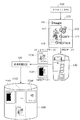
実施形態1の画像処理システムは、情報処理装置として参照されるクライアントPC100と画像処理装置120がネットワーク140で接続された環境で実現する。ここで、本実施形態のクライアントPCは、制御部(不図示)を有しており、クライアント環境(アプリケーション、OS、PDL)やドライバを制御する。また、画像処理装置120としては多機能複合機(MFP)とするが、これに限定されない。また、図1Aの構成は一例であり、ネットワーク140ではなくUSBなどでの直接接続でもよいし、クライアントPCやMFP自体が複数あっても問題ない。
The image processing system according to the first embodiment is realized in an environment in which a client PC 100 referred to as an information processing apparatus and the
一方、実施形態2の画像処理システムでは、クライアントPC100と画像処理装置120に、更に、図1Aに破線で示したプリントサーバ130がネットワーク140で接続された環境で、本発明が実現される。
On the other hand, in the image processing system according to the second embodiment, the present invention is realized in an environment in which the client PC 100 and the
<本実施形態の画像処理装置の構成例>
本実施形態を適用するに好適なMFPであるカラー複合機120の構成について、図1Bを用いて説明する。ここで説明する、カラー複合機は1つのドラムでカラー画像形成を行なう1Dカラー複合機である。
<Example of Configuration of Image Processing Device of Present Embodiment>
A configuration of the color multifunction peripheral 120, which is a suitable MFP for applying the present embodiment, will be described with reference to FIG. 1B. The color complex machine described here is a 1D color complex machine that forms a color image with one drum.
1Dカラー複合機は、スキャナ部(図中、原稿露光部)101、レーザ露光部102、感光ドラム103、作像部104、定着部105、給紙/搬送部106、及びこれらを制御する不図示のプリンタ制御部から構成される。
The 1D color multifunction peripheral includes a scanner unit (document exposure unit in the figure) 101, a
スキャナ部101は、原稿台に置かれた原稿に対して、照明を当てて原稿画像を光学的に読み取り、その像を電気信号に変換して画像データを作成する。 The scanner unit 101 illuminates a document placed on a document table, optically reads a document image, converts the image into an electrical signal, and creates image data.
レーザ露光部102は、作成及び受信した画像データに応じて、変調されたレーザ光などの光線を等角速度で回転する回転多面鏡(ポリゴンミラー)に入射させ、反射走査光として感光ドラム103に照射する。
The
作像部104は、以下の一連の電子写真プロセスを実行して作像する。感光ドラム103を回転駆動し、帯電器によって帯電させ、前記レーザ露光部102によって感光ドラム103上に形成された潜像をトナーによって現像化する。そして、そのトナー像をシートに転写する。転写されずに感光ドラム103上に残った微小トナーを回収する。その際、シートが転写ドラム107の所定位置に巻きつき、4回転する。その間に、マゼンタ(M)、シアン(C)、イエロー(Y)、ブラック(K)のトナーを持つそれぞれの現像ユニット(現像ステーション)が入れ替わりで順次前述の電子写真プロセスを繰り返し実行する。4回転の後、4色のフルカラートナー像を転写されたシートは、転写ドラム107を離れ、定着部105へ搬送される。
The
定着部105は、ローラやベルトの組み合わせによって構成され、ハロゲンヒータなどの熱源を内蔵し、前記作像部によってトナー像が転写されたシート上のトナーを、熱と圧力によって溶解、定着させる。
The
給紙/搬送部106は、シートカセットやペーパーデッキに代表されるシート収納庫を1つ以上持っている。そして、前記不図示のプリンタ制御部の指示に応じて、シート収納庫に収納された複数のシートの中から一枚分離し、作像部104から定着部105へ搬送する。シートは、作像部104の転写ドラム107に巻きつけられ、4回転した後に定着部105へ搬送される。4回転する間に前述のYMCK各色のトナー像がシートに転写される。また、シートの両面に画像形成する場合は、定着部105を通過したシートを再度、作像部104へ搬送する搬送経路を通るように制御する。
The sheet feeding /
不図示のプリンタ制御部は、カラー複合機全体を制御するコントロールユニットと通信して、その指示に応じて制御を実行する。そして、前述のスキャナ、レーザ露光、作像、定着、給紙/搬送の各部の状態を管理しながら、全体が調和を保って円滑に動作できるよう指示を行う。 A printer control unit (not shown) communicates with a control unit that controls the entire color multifunction peripheral and executes control in accordance with the instruction. Then, while managing the states of the scanner, laser exposure, image forming, fixing, and paper feeding / conveying units, an instruction is given so that the entire apparatus can operate smoothly and in harmony.
(コントロールユニットの構成例1)
図1Cは、本実施形態に係るカラー複合機120のコントロールユニット(コントローラとも言う)の一構成例を示すブロック図である。
(Control unit configuration example 1)
FIG. 1C is a block diagram illustrating a configuration example of a control unit (also referred to as a controller) of the color multifunction peripheral 120 according to the present embodiment.
図1Cにおいて、コントロールユニット200は、画像入力デバイスであるスキャナ201や画像出力デバイスであるプリンタエンジン202と接続し、画像データの読み取りやプリント出力のための制御を行う。また、コントロールユニット200は、LAN10や公衆回線204と接続することで、画像情報やデバイス情報をネットワーク経由で入出力するためのコントロールでもある。
In FIG. 1C, a
図1Cに示すコントロールユニット200において、CPU205はカラー複合機1の全体を制御するための中央処理装置である。RAM206は、CPU205が動作するためのシステムワークメモリであり、入力された画像データを一時記憶するための画像メモリでもある。RAM206には、画像データの外に以下のフローチャートの分岐で判断されるユーザにより設定入力された各種フラグも一次記憶される。さらに、ROM207はブートROMであり、システムのブートプログラムが格納されている。HDD208はハードディスクドライブであり、各種処理のためのシステムソフトウェア及び入力された画像データや文書ファイル等を格納する。
In the
なお、以下の図3及び図4に示す本実施形態のメタデータも、画像データと対応づけてHDD208に格納される。また、以下の図5、図6、図10、図12、図13のフローチャートで示されるプログラムを含む、CPU205で実行されるアプリケーションプログラムもHDD208に記憶されており、実行時にRAM206にロードされて実行される。あるいは、アプリケーションプログラムが、図示しないCDなどの外部記憶装置やネットワークを介してダウンロードされてもよい。
Note that the metadata of this embodiment shown in FIGS. 3 and 4 below is also stored in the
さらに、図1Cにおいて、操作部I/F209は、画像データ等を表示可能な表示画面を有する操作部210に対するインタフェース部であり、当該操作部210に対して画像データを出力する。また、操作部I/F209は、操作部210から操作者(すなわち、本画像処理システムの利用者)が入力した情報をCPU205に伝える役割をする。さらに、ネットワークインタフェース211は、例えばLANカードで実現され、図1Aのネットワーク140に相当するLAN10に接続して外部装置との間で情報の入出力を行う。さらにまた、モデム212は公衆回線204に接続し、外部装置との間で情報の入出力を行う。
1C, an operation unit I /
本実施形態に係るコントロールユニット200では、以上のデバイスがシステムバス213上に配置されている。
In the
次に、イメージバスI/F214は、システムバス213と画像データを高速で転送する画像バス215とを接続するためのインタフェースであり、データ構造を変換するバスブリッジである。画像バス215は、PCIバス又はIEEE1394で構成される。そして、画像バス215上には、以下で説明するRIP216、デバイスI/F217、スキャナ画像処理部218、プリンタ画像処理部219、画像編集用画像処理部220、カラーマネージメントモジュール(図中、CMM)230といったデバイスが接続される。
Next, the image bus I /
ラスタイメージプロセッサ(RIP)216は、ディスプレイリスト(DL)を解釈し、ラスタイメージ及びラスタイメージの各ピクセルに対応する属性ビットを作成(レンダリング)する。デバイスI/F部217は、スキャナ201やプリンタエンジン202とコントロールユニット200とを接続し、画像データの同期系/非同期系の変換を行う。
A raster image processor (RIP) 216 interprets the display list (DL) and creates (renders) attribute bits corresponding to the raster image and each pixel of the raster image. A device I /
また、スキャナ画像処理部218は、入力画像データに対して、補正、加工、編集等の各種処理を行う。プリンタ画像処理部219は、プリント出力画像データに対して、プリンタの補正、解像度変換等の処理を行う。画像編集用画像処理220は、画像データの回転や、画像データの圧縮伸長処理及び、RIP216の生成した属性ビットに基づいた各種画像処理を行う。さらに、CMM230は、画像データに対して、プロファイルやキャリブレーションデータに基づいた、色変換処理を施す専用ハードウェアモジュールである。
The scanner
[実施形態1]
<実施形態1の画像処理のデータフロー例>
上記画像処理システムの構成における実施形態1の画像処理のデータフロー例を、図2を使い説明する。
[Embodiment 1]
<Example of Data Flow of Image Processing of Embodiment 1>
A data flow example of image processing according to the first embodiment in the configuration of the image processing system will be described with reference to FIG.
クライアントPC100上のアプリケーションで作成された印刷データが、ドライバにて画像処理装置120に最適なPDLデータに変換される。そして、このPDLデータは、ネットワーク140を介してクライアントPC100から画像処理装置120へ転送される。本実施形態では、ページ110を印刷する場合を一例として考える。
Print data created by an application on the
ユーザが印刷しようとするページ110は、アプリケーションおよびドライバによって作成されたイメージオブジェクト、グラフィクスオブジェクト、テキストオブジェクトで構成されている。ページ110を詳細にみると、オブジェクト111および112はビットマップイメージとして作成され、オブジェクト113,115はグラフィクスオブジェクト、オブジェクト114はテキストオブジェクトから構成されている
これらのデータが、クライアントPC100からネットワーク140を介し画像処理装置120へPDLデータとして送信される。受信されたPDLデータは、画像処理装置120内のインタープリタにおいて、オブジェクトごとに中間データに変換されて、2次記憶装置(図1CのHDD208)に記憶される。
A
2次記憶装置(HDD208)内部では、ドキュメントを構成しているオブジェクトごとに保存することが可能である。各々のオブジェクトには、そのオブジェクトの特徴を示すメタデータを対応付けて付加させることが可能である。 In the secondary storage device (HDD 208), it is possible to save each object constituting the document. Each object can be associated with metadata indicating the characteristics of the object.
<本実施形態のメタデータの構成例>
次に、図3を用いて画像処理装置120のHDD208内に保持されるメタデータの構成を説明する。
<Configuration example of metadata of this embodiment>
Next, the configuration of metadata held in the
メタデータは図3に示したとおり階層構造を有している。例えば、メタデータとして最上位層には、画像処理装置120の情報や基本的情報を保持する機器内共通の機器内共通メタデータ300がある。機器内共通メタデータ300の下位層に、画像処理装置120で処理される各ジョブの情報を保持するジョブ内共通のジョブ内共通メタデータ301、302がある。ジョブ内共通メタデータ301、302には、このメタデータ内にジョブ投入された作成日や作成者、作成されたアプリケーション名、ドライバのバージョン、PDL名称、その各々のバージョン番号などが記述されている。
The metadata has a hierarchical structure as shown in FIG. For example, in the uppermost layer as metadata, there is in-device
また、ジョブ内共通メタデータ301、302の下位層に、各ジョブに含まれるページ毎のページ内共通メタデータ310、320がある。このページ毎のページ内共通メタデータ310、320内には、該当ページのサイズ、メディア、カラー情報などが記述されている。
Further, in-layer
続いて、ページ毎のページ内共通メタデータ310、320の下位層に、各ページ内のオブジェクト単位のメタデータ311がある。オブジェクト単位のメタデータ311内には、オブジェクトの属性(Graphics,Image,Text)などが記述され、例えばTextオブジェクトの場合はそのテキスト内容などが保持されている。
Subsequently, in the lower layer of the in-page
(メタデータの内容の具体例)
図4を用いてメタデータの具体例を説明する。なお、図4はメタデータの一例であって、その用途や目的に従って有効な項目が準備されればよい。
(Specific examples of metadata contents)
A specific example of metadata will be described with reference to FIG. Note that FIG. 4 is an example of metadata, and an effective item may be prepared according to its use and purpose.
まず、機器内共通メタデータ300として、機器名称、属性修正情報など機器として共通のデータを保持している。次に、ジョブ内共通メタデータ301として、ジョブ投入日時、ジョブ作成者、アプリ、OS、PDLなどの情報を保持している。次に、ページ内共通メタデータ310として、サイズやメディアなどを保持している。
First, as the in-device
続いて、オブジェクトごとのメタデータ311については、3種類の属性ごとに説明する。まず、テキストオブジェクトのメタデータ例311−1は、属性情報(図の<属性>)、フォント名(図の<名称>)、サイズ(図の<サイズ>)、内容(図の<内容>)を保持する。また、グラフィクス属性のメタデータ例311−2として、属性情報(図の<属性>)と関数などのグラフィクスの情報(図の<情報>)を持つ。次に、イメージ属性のメタデータ例311−3として、属性情報(図の<属性>)および圧縮方式などの情報(図の<情報>)を持つ。ここで、ジョブ内共通メタデータ301で規定されているICCProfileタグを再びイメージ属性のメタデータ例311−3内で定義しているが、このような利用方法も問題ない。
Subsequently, the
なお、メタデータの記載に関して、本実施形態では記述言語としてXMLを使用したが、記述方式は自由である。 Regarding the description of metadata, in this embodiment, XML is used as a description language, but the description method is arbitrary.
<実施形態1の画像処理の手順例>
以下、上記本実施形態の画像処理システムの構成による、画像処理の手順を詳細に説明する。
<Example of Image Processing Procedure of First Embodiment>
Hereinafter, the procedure of image processing according to the configuration of the image processing system of the present embodiment will be described in detail.
<PDL印刷におけるユーザ指示による属性再評価を含む手順例>
図5のフローチャートを用いて、ユーザの指示によるオブジェクト属性再評価方法の手順例に関して説明する。図5において、ステップS501とS502はクライアントPC100における処理である。ステップS503以降が画像処理装置120の処理であり、CPU205により実行される。
<Example procedure including attribute re-evaluation by user instruction in PDL printing>
A procedure example of the object attribute reevaluation method in accordance with a user instruction will be described with reference to the flowchart of FIG. In FIG. 5, steps S501 and S502 are processes in the
まず、ユーザは通常、クライアントPC100上のアプリケーションでデータを作成する(S501)。アプリケーションから印刷指示を行うと、選択されたドライバにて該当画像処理装置120にて処理可能なPDLデータへと変換され、ネットワーク140上をPDLデータが送信される(S502)。
First, the user usually creates data with an application on the client PC 100 (S501). When a print instruction is issued from the application, the data is converted into PDL data that can be processed by the corresponding
画像処理装置120にてPDLデータを受信し、PDLデータを解釈するためにPDLインタープリタにて処理を行う(S503)。インタープリタの処理が終了すると、PDLデータはPDLに依存しない中間データに変換される(S504)。その後、中間データは2次記憶装置(HDD208)にスプールされる(S505)。
The PDL data is received by the
次に、オブジェクトの属性再評価を指示可能な属性再評価UI(図7)を画面生成し、その生成された画面の表示をクライアントPC100に対して指示する(S506)。なお、かかる表示はWebブラウザを介するのが望ましいがこれに限定されない。クライアントPC100上の表示画面(図7)から再評価オブジェクトが選択され、続いて実行ボタン(図8のスタート701に相当)が押されたことを認識すると、CPU205はステップS507からS508に分岐する。選択された再評価オブジェクトに対してOCR処理などにより文字認識を行い(S508)、HDD208内のメタデータを更新する(S509)。
Next, an attribute reevaluation UI (FIG. 7) capable of instructing attribute reevaluation of the object is generated on the screen, and the
その後、再評価が実行されても実行されなくても、メタデータに基づいて、ステップS504で変換した中間データをレンダリングして(S510)、印刷する(S511)。 Thereafter, whether the re-evaluation is executed or not, the intermediate data converted in step S504 is rendered based on the metadata (S510) and printed (S511).
(メタデータ更新:S509の処理手順例)
図5におけるメタデータの更新(S509)の手順例の詳細な説明を、図6のフローチャートを使って説明する。
(Metadata update: example of processing procedure in S509)
A detailed description of an example of the procedure for updating metadata (S509) in FIG. 5 will be described with reference to the flowchart in FIG.
まず、OCR処理(S508)などの結果から、属性情報の変更があったかどうかを確認する(S1001)。 First, it is confirmed from the result of the OCR process (S508) whether or not the attribute information has been changed (S1001).
属性情報の変更があった場合には、アプリケーションによって最初に付与された属性である元属性がイメージで、この元属性を改めてテキストに変更するかどうかを判断する(S1002)。変更すると判断された場合は、まずメタデータ311内の属性情報(<属性>)を"イメージ"から"テキスト"に変更する(S1003)。OCR処理でフォント名が分かったかどうかを判断し(S1004)、分かった場合はメタデータのフィント名(<名称>)へ追加する(S1005)。同様に、フォントサイズ(<サイズ>)もメタデータ311へ追加し(S1006)、判明したテキストの内容も同様にメタデータの内容(<内容>)へ追加する(S1007)。
If the attribute information has been changed, the original attribute, which is the attribute initially given by the application, is an image, and it is determined whether or not this original attribute is to be changed to text again (S1002). If it is determined to be changed, the attribute information (<attribute>) in the
次に、機器内共通メタデータ300の属性修正情報タグ(<属性修正情報>)における環境タグ(<環境>)を検索し(S1008)、同一の環境情報があるかどうか判断する(S1009)。同一の環境情報がない場合は、新規に環境タグを作成し(S1010)、修正回数タグ(<修正回数>)をインクリメントする(S1011)。かかる修正回数タグ(<修正回数>)は、属性変更の種類の数だけ準備されている。
ここで、同一の環境とは、クライアント環境(アプリケーション、OS、PDL)が同じことを指す。
Next, the environment tag (<environment>) in the attribute modification information tag (<attribute modification information>) of the in-device
Here, the same environment refers to the same client environment (application, OS, PDL).
ステップS1002においてイメージからテキストの変更ではなかった場合、グラフィクスからテキストへの変更か判断する(S1012)。もしこのグラフィックスからテキストへの変更であった場合は、イメージからテキストと同様の処理を行う。もしイメージからグラフィクスへの変更であった場合(S1013)、メタデータ311内の属性情報タグ(<属性>)を"イメージ"から"グラフィック"に変更し(S1014)、情報タグ(<情報>)も追加する(S1015)。
If it is not the change from the image to the text in step S1002, it is determined whether the change is from the graphics to the text (S1012). If it is a change from graphics to text, the same processing is performed from the image to text. If the change is from image to graphics (S1013), the attribute information tag (<attribute>) in the
<本実施形態の指示UIの表示画面例>
次に図7、図8、図9を用いて、図5のステップS506におけるUIによる属性再評価指示の一例を示す。クライアントPC100の表示画面には、指定ジョブに含まれるオブジェクトすべてが一覧として表示される。なお、大量のオブジェクトがある場合には、各オブジェクトの縮小表示やスクロール、あるいは複数ページ表示などが考えられる。
<Example of display screen of instruction UI of this embodiment>
Next, an example of an attribute re-evaluation instruction by the UI in step S506 in FIG. 5 will be described with reference to FIGS. On the display screen of the
(オブジェクト一覧画面:図7)
まず、図7のオブジェクト一覧画面の表示がクライアントPC100に指示される。かかるオブジェクト一覧画面にて、ユーザは例えば属性を再評価したいオブジェクト601を選択する。本実施形態では、PDLデータにおいては、アプリケーションによりイメージ属性として元属性を付与され、画像処理装置120へ送信されたオブジェクトを選択するものとする。
(Object list screen: Fig. 7)
First, the
602−1にオブジェクト601のメタデータを示す。ユーザによるオブジェクト601の選択が画像処理装置120に通知されると、クライアントPCの制御部によって自動的に対応するメタデータ602−1の表示が指示されるのが望ましい。
Reference numeral 602-1 denotes metadata of the
(属性再評価指示画面:図8)
図7でユーザによってオブジェクト601の選択が通知されると、クライアントPCの制御部は図8に表示画面を遷移させる。
(Attribute re-evaluation instruction screen: FIG. 8)
When the selection of the
図8の表示画面で、ユーザがスタートボタン701を押下することにより、このユーザからの指示をクライアントの制御部が受け、属性再評価の指示をクライアントPCから画像処理装置120に通知する。
通知を受けた画像処理装置120は、属性再評価作業を開始する。
When the user presses the
Upon receiving the notification, the
(属性再評価後のオブジェクト一覧画面:図9)
属性再評価作業が終了すると、図9のように再度オブジェクト一覧画面に表示画面を遷移させる。ここで、ユーザがオブジェクト601を選択してメタデータを確認すると、オブジェクト601対応するメタデータ602−2の表示が指示される。メタデータ602−2は、図7にてアプリケーションによって最初に付与された属性であるイメージオブジェクトから、OCR処理などによりテキスト属性として再認識されて変更された属性や内容に変更されている。
(Object list screen after attribute reevaluation: Fig. 9)
When the attribute re-evaluation work is completed, the display screen is changed again to the object list screen as shown in FIG. Here, when the user selects the
<属性再評価以降のジョブ投入時の処理手順例>
図10のフローチャートを用いて、属性再評価以降のジョブ投入時の処理手順例の説明を行う。かかる図10においても、図5と同様に、ステップS901とS902はクライアントPC100における処理である。ステップS903以降が画像処理装置120の処理であり、CPU205により実行される。
<Example of processing procedure when submitting job after attribute re-evaluation>
An example of a processing procedure at the time of job submission after attribute re-evaluation will be described using the flowchart of FIG. Also in FIG. 10, steps S901 and S902 are processes in the
クライアントPC100においてアプリケーションにて印刷データを作成する(S901)。アプリケーションから印刷指示を行うと、選択されたドライバにて該当画像処理装置にて処理可能なPDLデータへと変換され、クライアントPC100から画像処理装置120へPDLデータが送信される(S902)。
Print data is created by an application in the client PC 100 (S901). When a print instruction is issued from the application, the data is converted into PDL data that can be processed by the selected image processing apparatus using the selected driver, and the PDL data is transmitted from the
画像処理装置120が受信したPDLデータは、画像処理装置120内のPDLインタープリタにてインタープリタ処理を行う(S903)。インタープリタの処理の結果、PDL言語に依存しない中間データに変換され(S904)、メタデータが作成される(S905)。
The PDL data received by the
その際に、機器内共通メタデータ300における属性修正情報タグ(<属性修正情報>)内の環境(<環境>)を検索し、受信したPDLデータを処理した環境が、過去に修正済みのユーザ環境か否かを確認する(S906)。もし、過去にユーザが修正済みでない場合は、図5と同様に、中間データをスプールし(S907)、クライアントPC100に対して属性再評価UI表示の指示を行う(S908)。なお、図10では、図5のステップS507からS509の再評価実行処理は、煩雑さを避けるために省略されている。
At that time, the environment (<environment>) in the attribute correction information tag (<attribute correction information>) in the in-device
ステップS906の判定において、受信したPDLデータを処理した環境が過去に修正したことのあるユーザ環境であった場合は、該当オブジェクトがグラフィクスであるかどうかを判断する(S909)。判断結果がもしグラフィクスの場合は該当オブジェクトを一旦レンダリングする(S910)。
つまり、1度属性を修正した環境を有するクライアントから送信されたデータに関しては、オブジェクトの属性の修正を自動的に行う。
If it is determined in step S906 that the environment in which the received PDL data has been processed is a user environment that has been corrected in the past, it is determined whether or not the corresponding object is graphics (S909). If the determination result is graphics, the object is once rendered (S910).
That is, with respect to data transmitted from a client having an environment in which the attribute is corrected once, the attribute of the object is automatically corrected.
ステップS910でレンダリングした結果、又はテキストやイメージのオブジェクトをOCR処理にかけてテキスト判定し(S911)、新オブジェクトおよび新メタデータを作成し(S912)、既存中間データと合成する(S913)。 The result of rendering in step S910, or text or image object is subjected to OCR processing to determine text (S911), a new object and new metadata are created (S912), and synthesized with existing intermediate data (S913).
ユーザ指示の属性再評価、ユーザ環境が同じための自動属性再評価、再評価なし、のいずれの場合も、ページ全体をレンダリング処理し(S914)、その結果を印刷する(S915)。 In any case of attribute re-evaluation of the user instruction, automatic attribute re-evaluation for the same user environment, and no re-evaluation, the entire page is rendered (S914), and the result is printed (S915).
上記処理手順により、ユーザが一度属性情報を修正した(再評価した)環境においては、修正以降はユーザが再度指定することなく自動的に属性情報の再評価処理を施すことが可能となる。また、再評価が必要でないユーザ環境においては一致するユーザ環境が保持されてないので、再評価処理は実行されない。そのため、常に再評価の処理時間がかかるという問題も避けることが可能となる。 According to the above processing procedure, in an environment in which the user has corrected (re-evaluated) the attribute information, the attribute information can be automatically re-evaluated after the correction without being designated again by the user. In addition, in a user environment that does not require re-evaluation, a matching user environment is not held, so that the re-evaluation process is not executed. Therefore, it is possible to avoid the problem that it always takes a re-evaluation processing time.
[実施形態2]
以下、本発明の実施形態2について、図面を用いて詳細に説明する。
[Embodiment 2]
Hereinafter, Embodiment 2 of the present invention will be described in detail with reference to the drawings.
<実施形態2の画像処理のデータフロー例>
本実施形態2では、図11のデータフローを用いて、図1Aに破線で示した画像処理サーバとして参照されるプリントサーバ130が接続された形態での、属性情報再評価方法について説明する。
<Example of Data Flow of Image Processing of Second Embodiment>
In the second embodiment, an attribute information reevaluation method in a form in which a
クライアントPC100上のアプリケーションにて印刷データを作成し、ドライバを用いてプリントサーバ130が理解できるPDLデータに変換し、PDLデータ110をプリントサーバ130へ送信する。
Print data is created by an application on the
プリントサーバ130では、受信したPDLデータをレンダリング(展開)したビットマップデータ1130と属性データ1131とを、画像処理装置120へ転送する。本実施形態2では、一例として属性データ1131において、図2と同様に、113と115はグラフィクスオブジェクト、111と112はイメージオブジェクト、114はテキストオブジェクトとした。
In the
画像処理装置120では、受信したレンダリング済みのビットマップデータ1130と属性データ1131とを、2次記憶装置(HDD208)に保存する。特に、属性データ1131は、イメージ部分1142と、テキスト部分1143と、グラフィクス部分1144とを分解して保持する。
The
<実施形態2の画像処理の手順例>
図12のフローチャートを用いて、実施形態2における画像処理の手順例を説明する。なお、図12においては、ステップS1201とS1202はクライアントPC100における処理である。ステップS1203はプリントサーバ130における処理である。ステップS1204以降が画像処理装置120の処理であり、CPU205により実行される。
<Example of Image Processing Procedure of Second Embodiment>
An example of an image processing procedure according to the second embodiment will be described with reference to the flowchart of FIG. In FIG. 12, steps S1201 and S1202 are processes in the
実施形態1と同様に、アプリケーションで印刷データを作成し(S1201)、ドライバでPDLデータを生成してプリントサーバ130に送信する(S1202)。 As in the first embodiment, print data is created by an application (S1201), PDL data is generated by a driver and transmitted to the print server 130 (S1202).
PDLデータをプリントサーバ130が受信する。プリントサーバ130にて、PDLデータからレンダリング済みのビットマップデータ1130および属性データ1131を生成し、画像処理装置120に転送する(S1203)。
The
ビットマップデータ1130および属性データ1131を受信した画像処理装置120は、実施形態1における図6から図8と同様のUI表示を指示する(S1205)。
The
ユーザにより再評価を実行するオブジェクトが選択されて、再評価の実行指示があったかを判断する(S1206)。再評価の実行指示の通知を受けると、再評価実行と判断したオブジェクトに対して、該当箇所にOCR処理を行い(S1207)、その結果からメタデータを実施形態1の図6と同様の手順で更新する(S1208)。その後、属性データ1142〜1144の該当部分を変更する(S1209)。
It is determined whether an object to be re-evaluated is selected by the user and a re-evaluation execution instruction has been issued (S1206). When the notification of the re-evaluation execution instruction is received, the OCR process is performed on the corresponding part for the object determined to be re-evaluation execution (S1207), and the metadata is obtained from the result in the same procedure as in FIG. 6 of the first embodiment. Update (S1208). Thereafter, the corresponding part of the
ビットマップデータ1130と属性データ1131に基づき印刷を行う(S1210)。
Printing is performed based on the
その後、次回以降の処理、つまり属性再評価以降のジョブ投入後の処理に関しては実施形態1における処理と同等であるため省略する。
実施形態2のプリントサーバ130を用いた環境にて、PDLデータを印刷処理する際も、実施形態1と同様にユーザが一度属性情報を修正した環境において、修正以降は自動的に属性情報の再評価処理を施すことが可能となる。
また、再評価が必要でないユーザ環境においては一致するユーザ環境が保持されてないので、再評価処理は実行されない。そのため、常に再評価の処理時間がかかるという問題も避けることが可能となる。
また、実施形態2では、レンダリング処理が終了した後に画像処理装置へデータを送信するので、画像処理装置内での処理の手間が省ける。
Thereafter, the processing after the next time, that is, the processing after the job input after attribute re-evaluation is the same as the processing in the first embodiment, and the description thereof is omitted.
When PDL data is printed in an environment using the
In addition, in a user environment that does not require re-evaluation, a matching user environment is not held, so that the re-evaluation process is not executed. Therefore, it is possible to avoid the problem that it always takes a re-evaluation processing time.
In the second embodiment, since the data is transmitted to the image processing apparatus after the rendering process is completed, the processing time in the image processing apparatus can be saved.
また、プリントサーバ130を用いないPDLデータの印刷処理の系においても、実施形態2と同様に、レンダリング処理が終了した後に実施形態2と同様の処理を行っても同等であり、同様の効果が奏される。
Also, in the PDL data printing process system that does not use the
[実施形態3]
上記実施形態では、クライアントPC100の表示画面に、指定ジョブに含まれるオブジェクトすべてが一覧として表示される例を説明した。しかしながら、属性修正指示を行う際にオブジェクト数が大量にある場合は、目的のオブジェクトを検索するのに非常に手間がかかる。
[Embodiment 3]
In the above-described embodiment, an example in which all objects included in the specified job are displayed as a list on the display screen of the
本実施形態3では、クライアントPC100の表示画面に表示されるオブジェクトの数を適切に制限して、目的のオブジェクトの検索を容易にできて属性再評価をするオブジェクトを選択可能な処理例を示す。
In the third embodiment, a processing example in which the number of objects displayed on the display screen of the
<属性再評価UI表示の一手順例>
図13のフローチャートを用いて、UI画面に表示するオブジェクトを選択する処理手順を説明する。なお、かかる図13の処理は、上記実施形態における「属性再評価UI表示指示」の処理に適用される。
<Example of procedure for attribute re-evaluation UI display>
A processing procedure for selecting an object to be displayed on the UI screen will be described with reference to the flowchart of FIG. The process of FIG. 13 is applied to the “attribute re-evaluation UI display instruction” process in the above embodiment.
まず、中間データからオブジェクトを選択し(S1301)、テキストオブジェクトか否かを判断する(S1302)。テキストオブジェクトの場合は、UI選択対象とはならないため直ちにステップS1301に戻って次のオブジェクトを選択する。 First, an object is selected from the intermediate data (S1301), and it is determined whether it is a text object (S1302). In the case of a text object, since it is not a UI selection target, the process immediately returns to step S1301 to select the next object.
もしテキストオブジェクトでなかった場合は、オブジェクトサイズを確認し、あるサイズ以上の大きさであるか否かを判断する(S1303)。このサイズが小さい場合、テキストオブジェクトである可能性が少ないと考えられるので、もし非常に小さなサイズのオブジェクトであった場合は、UI表示対象とせずにステップS1301に戻って次のオブジェクトを選択する。 If it is not a text object, the object size is confirmed, and it is determined whether or not the object is larger than a certain size (S1303). If this size is small, it is considered that there is little possibility of being a text object. If it is an extremely small object, the process returns to step S1301 without selecting a UI display target, and the next object is selected.
ある大きさ以上の大きさであると判断した場合は、単純なフィル(fill)図形か否かを判断するためにエッジの個数をカウントする(S1304)。エッジの数が所定数以上であるか否かを判断する(S1305)。このエッジ数が少ない場合、テキストオブジェクトである可能性が少ないと考えられるので、エッジがテキストオブジェクトではない程の所定数より少なかった場合もUI表示対象とせずに、ステップS1301に戻って次のオブジェクトを選択する。 If it is determined that the size is greater than a certain size, the number of edges is counted in order to determine whether or not it is a simple fill graphic (S1304). It is determined whether or not the number of edges is equal to or greater than a predetermined number (S1305). If the number of edges is small, it is considered that the possibility of being a text object is low. Therefore, even when the number of edges is less than a predetermined number that is not a text object, the UI returns to step S1301 without returning to the next object. Select.
エッジの数が所定数以上であった場合に、初めてUI表示対象のオブジェクトと選別してメタデータ内にマークし、クライアントPC100への表示画面に付加して(S1306)、処理を終了する。 When the number of edges is equal to or larger than the predetermined number, the object is first selected as a UI display target object, marked in the metadata, added to the display screen on the client PC 100 (S1306), and the process ends.
なお、しきい値のエッジの数は固定値であっても、変更可能であってもよい。表示画面のサイズやオブジェクトの個数などに対応して、適切なエッジの数が選択されるのが望ましい。 Note that the number of threshold edges may be a fixed value or changeable. It is desirable to select an appropriate number of edges corresponding to the size of the display screen, the number of objects, and the like.
実施形態3によって、クライアントPC100の表示画面に、指定ジョブに含まれるオブジェクトが大量にある際、全てのオブジェクトではなく、ある条件を満たした一部のオブジェクトのみを画面に表示するため、目的のオブジェクトを検索することが容易になる。
According to the third embodiment, when there are a large number of objects included in the specified job on the display screen of the
[実施形態4]
本実施形態では、UI画面に表示するオブジェクトを選択する他の例を示す。
[Embodiment 4]
In the present embodiment, another example of selecting an object to be displayed on the UI screen is shown.
<属性再評価UI表示の他の手順例>
実施形態4では、実施形態1乃至3における、図7の表示画面内のオブジェクト一覧表示おいて、グラフィクスオブジェクトのみ、又はイメージオブジェクトのみを選別して表示画面を生成する。かかるオプションは、上記実施形態3と組み合わせても実行可能である。
<Other example procedures for displaying attribute re-evaluation UI>
In the fourth embodiment, in the object list display in the display screen of FIG. 7 in the first to third embodiments, only the graphics object or only the image object is selected to generate the display screen. Such an option can also be executed in combination with the third embodiment.
実施形態4によってオブジェクトの属性ごとに、表示画面内に一覧表示するため、目的のオブジェクトのを検索しやすくなる上に、変更時の操作が容易になる。 According to the fourth embodiment, a list is displayed on the display screen for each attribute of the object, so that it becomes easy to search for a target object and an operation at the time of change is facilitated.
[その他の実施形態]
なお、本実施形態では、PDLデータによる印刷ジョブにより本発明の特徴を説明したが、本発明はPDLデータによる印刷ジョブに限定されない。例えば、本実施形態の画像処理装置120は多機能複写機であるので、スキャナ読込み処理、複写処理、データ送受信処理、ファクシミリ送受信処理などにも、同様に適用できる。
[Other Embodiments]
In the present embodiment, the features of the present invention have been described using a print job using PDL data. However, the present invention is not limited to a print job using PDL data. For example, since the
更に、画像処理装置120をクライアント装置やサーバ装置に置き換えても本発明は有効であり、これらも本発明に含まれる。
Furthermore, the present invention is effective even if the
また、本発明は、複数の機器(例えばホストコンピュータ、インタフェース機器、プリンタなど)から構成されるシステムあるいは統合装置に適用しても、ひとつの機器からなる装置に適用してもよい。 In addition, the present invention may be applied to a system or an integrated device including a plurality of devices (for example, a host computer, an interface device, a printer, etc.) or an apparatus including a single device.
又、本発明の目的は、前述した実施形態の機能を実現するソフトウェアのプログラムコードを記録した記憶媒体(または記録媒体)を、システムあるいは装置に供給する。そして、そのシステムあるいは装置のコンピュータ(またはCPUやMPU)が記憶媒体に格納されたプログラムコードを読み出し実行することによっても、達成されることは言うまでもない。この場合、記憶媒体から読み出されたプログラムコード自体が前述した実施形態の機能を実現することになり、そのプログラムコードを記憶した記憶媒体は本発明を構成することになる。又、コンピュータが読み出したプログラムコードを実行することにより、前述した実施形態の機能が実現されるだけではない。そのプログラムコードの指示に基づき、コンピュータ上で稼働しているオペレーティングシステム(OS)などが実際の処理の一部または全部を行い、その処理によって前述した実施形態の機能が実現される場合も含まれることは言うまでもない。 Another object of the present invention is to supply a storage medium (or recording medium) in which a program code of software that realizes the functions of the above-described embodiments is recorded to a system or apparatus. Needless to say, this can also be achieved by the computer (or CPU or MPU) of the system or apparatus reading and executing the program code stored in the storage medium. In this case, the program code itself read from the storage medium realizes the functions of the above-described embodiments, and the storage medium storing the program code constitutes the present invention. The functions of the above-described embodiments are not only realized by executing the program code read by the computer. This includes the case where the operating system (OS) running on the computer performs part or all of the actual processing based on the instruction of the program code, and the functions of the above-described embodiments are realized by the processing. Needless to say.
さらに、記憶媒体から読み出されたプログラムコードが、コンピュータに挿入された機能拡張カードやコンピュータに接続された機能拡張ユニットに備わるメモリに書込まれる。その後、そのプログラムコードの指示に基づき、その機能拡張カードや機能拡張ユニットに備わるCPUなどが実際の処理の一部または全部を行なう。このような処理によって前述した実施形態の機能が実現される場合も含まれることは言うまでもない。 Further, the program code read from the storage medium is written in a memory provided in a function expansion card inserted into the computer or a function expansion unit connected to the computer. Thereafter, based on the instruction of the program code, the CPU or the like provided in the function expansion card or function expansion unit performs part or all of the actual processing. It goes without saying that the case where the functions of the above-described embodiments are realized by such processing is also included.
本発明を上記記憶媒体に適用する場合、その記憶媒体には、先に説明したフローチャートに対応するプログラムコードが格納されることになる。 When the present invention is applied to the storage medium, the storage medium stores program codes corresponding to the flowcharts described above.
Claims (17)
前記クライアントの動作環境を、前記画像を構成するオブジェクトのメタデータとして保存する保存手段と、
前記受信手段にて受信したオブジェクトの属性を評価する評価手段と、
前記評価手段によって属性を評価されたオブジェクトの属性を再評価することが指示された場合に、前記属性の再評価を行った記録をメタデータとして記録する記録手段と、
前記画像とは別の画像を受信する際、該画像に対して画像処理の指示をしたクライアントの動作環境が前記保存手段によって保存されたクライアントの動作環境と同一で、前記記録手段によって属性の再評価を行った記録が有る場合に、受信した前記別の画像を構成するオブジェクトの属性の再評価を実行する実行手段と
を有することを特徴とする画像処理装置。 Receiving means for receiving the objects constituting the image and the image from the client,
Storage means for storing the operating environment of the client as metadata of objects constituting the image;
Evaluation means for evaluating the attributes of the object received by the receiving means;
A recording unit that records a record of the re-evaluation of the attribute as metadata when instructed to reevaluate the attribute of the object whose attribute is evaluated by the evaluation unit;
When an image different from the image is received, the operating environment of the client that instructed the image processing for the image is the same as the operating environment of the client stored by the storing unit, and attribute recording is performed by the recording unit. An image processing apparatus comprising: execution means for executing re-evaluation of an attribute of an object constituting the received another image when there is a record of evaluation.
属性の再評価の結果に基づいて、前記オブジェクトの属性を更新する更新手段と
を更に有することを特徴とする請求項1に記載の画像処理装置。 Display instruction means for instructing display of a screen capable of instructing re-evaluation of the attribute of the object;
The image processing apparatus according to claim 1, further comprising an update unit configured to update the attribute of the object based on a result of attribute re-evaluation.
前記クライアントの動作環境と属性の再評価の記録は、前記クライアントから前記画像を受信した装置に共通のメタデータとして保持され、
前記オブジェクトの属性は、前記装置に共通のメタデータの下位層のオブジェクト単位のメタデータとして保持されることを特徴とする請求項1乃至3のいずれ一項に記載の画像処理装置。 The metadata is held in a hierarchical structure,
A record of the client's operating environment and attribute reevaluation is maintained as metadata common to the device that received the image from the client,
The attributes of the object, an image processing apparatus according to any one of claims 1 to 3, characterized in that it is held as the metadata of the object unit of the lower layer of the common metadata to the device.
前記オブジェクト単位に保存されたメタデータは、前記ページに共通のメタデータの下位層として保持されることを特徴とする請求項4に記載の画像処理装置。 The hierarchical structure of the metadata is held in metadata common to jobs held in a lower layer of metadata common to apparatuses receiving the image from the client, and held in a lower layer of metadata common to the jobs. Metadata that is common to all pages
The image processing apparatus according to claim 4, wherein the metadata stored in units of objects is held as a lower layer of metadata common to the pages.
前記画面生成手段は、前記選別されたオブジェクトから前記属性の再評価を行うオブジェクトを選択することが可能になるように表示する画面を生成することを特徴とする請求項6に記載の画像処理装置。 The display instruction means includes a selection means for selecting an object from objects included in one job based on the size of the object and the number of edges of the object,
The image processing apparatus according to claim 6, wherein the screen generation unit generates a screen to be displayed so that an object for which the attribute is re-evaluated can be selected from the selected objects. .
前記画面生成手段は、前記選別されたオブジェクトから前記属性の再評価を行うオブジェクトを選択可能に表示する画面を生成することを特徴とする請求項6に記載の画像処理装置。 The display instruction means includes a selection means for selecting a graphics object or an image object from objects included in one job,
The image processing apparatus according to claim 6, wherein the screen generation unit generates a screen for selectively displaying an object on which the attribute is re-evaluated from the selected objects.
過去に前記クライアントから別の画像を受信し、該別の画像を構成するオブジェクトに対して評価された属性の再評価を行ったという情報がある場合、前記受信手段にて受信した画像を構成するオブジェクトに対して属性の再評価を実行する実行手段と
を有することを特徴とする画像処理装置。 Receiving means for receiving an image from a client;
If there is information that a different image has been received from the client in the past and the attribute evaluated for the object constituting the different image has been re-evaluated, the image received by the receiving unit is configured. the image processing apparatus characterized by having a <br/> and execution means for executing a re-evaluation of the attribute for the objects.
保存手段が、前記クライアントの動作環境を、前記画像を構成するオブジェクトのメタデータとして記憶部に保存する保存工程と、
評価手段が、前記受信工程にて受信したオブジェクトの属性を評価する評価工程と、
記録手段が、前記評価工程によって属性を評価されたオブジェクトの属性を再評価することが指示された場合に、前記属性の再評価を行った記録をメタデータとして記憶部に記録する記録工程と、
実行手段が、前記画像とは別の画像を受信する際、該画像に対して画像処理の指示をしたクライアントの動作環境が前記保存工程にて保存されたクライアントの動作環境と同一で、前記属性の再評価を行った記録が有る場合に、受信した前記別の画像を構成するオブジェクトの属性の再評価を実行する実行工程と
を有することを特徴とする画像処理方法。 A receiving step in which a receiving means receives an image processing instruction for an image and an object constituting the image from a client ;
A storage unit that stores the operating environment of the client in a storage unit as metadata of an object constituting the image;
An evaluation means for evaluating an attribute of the object received in the reception step;
When the recording means is instructed to reevaluate the attribute of the object whose attribute has been evaluated by the evaluation step, a recording step of recording a record in which the attribute is reevaluated as metadata in a storage unit ;
When the execution means receives an image different from the image, the operating environment of the client that instructed the image processing to the image is the same as the operating environment of the client stored in the storing step, and the attribute An image processing method comprising: executing a re-evaluation of an attribute of an object constituting the received another image when there is a record in which the re-evaluation is performed.
更新手段が、属性再評価の結果に基づいて、前記オブジェクトの属性を更新する更新工程と
を更に有することを特徴とする請求項12に記載の画像処理方法。 A display instruction step for instructing display of a screen on which display instruction means can instruct attribute re-evaluation of the object;
Updating means, based on the result of the attribute reevaluation, image processing method according to claim 12, further comprising an update step of updating the attributes of the object.
1つのジョブに含まれるオブジェクトから、オブジェクトのサイズ及びオブジェクトのエッジ数に基づいてオブジェクトを選別する選別工程と、
前記選別されたオブジェクトを選択可能に表示する画面を生成する画面生成工程と
を有することを特徴とする請求項13に記載の画像処理方法。 The display instruction step includes
A selection step of selecting an object from objects included in one job based on the size of the object and the number of edges of the object;
The image processing method according to claim 13, further comprising: a screen generation step of generating a screen that displays the selected objects in a selectable manner.
実行手段が、過去に前記クライアントから別の画像を受信し、該別の画像を構成するオブジェクトに対して評価された属性の再評価を行ったという情報がある場合、前記受信工程にて受信した画像を構成するオブジェクトに対して属性の再評価を実行する実行工程と
を有することを特徴とする画像処理方法。 A receiving step in which the receiving means receives the image from the client ;
When there is information that the execution means has received another image from the client in the past and re-evaluated the attribute evaluated for the object constituting the other image, the information is received in the receiving step an image processing method characterized by having a <br/> and execution step of executing the re-evaluation of the attribute for the objects constituting the image.
Priority Applications (2)
| Application Number | Priority Date | Filing Date | Title |
|---|---|---|---|
| JP2008128790A JP5022986B2 (en) | 2008-05-15 | 2008-05-15 | Image processing apparatus, image processing method, and program for executing image processing method |
| US12/433,900 US8264744B2 (en) | 2008-05-15 | 2009-05-01 | Image processing apparatus, image processing method, and program to execute image processing method |
Applications Claiming Priority (1)
| Application Number | Priority Date | Filing Date | Title |
|---|---|---|---|
| JP2008128790A JP5022986B2 (en) | 2008-05-15 | 2008-05-15 | Image processing apparatus, image processing method, and program for executing image processing method |
Publications (3)
| Publication Number | Publication Date |
|---|---|
| JP2009277092A JP2009277092A (en) | 2009-11-26 |
| JP2009277092A5 JP2009277092A5 (en) | 2011-08-18 |
| JP5022986B2 true JP5022986B2 (en) | 2012-09-12 |
Family
ID=41315861
Family Applications (1)
| Application Number | Title | Priority Date | Filing Date |
|---|---|---|---|
| JP2008128790A Expired - Fee Related JP5022986B2 (en) | 2008-05-15 | 2008-05-15 | Image processing apparatus, image processing method, and program for executing image processing method |
Country Status (2)
| Country | Link |
|---|---|
| US (1) | US8264744B2 (en) |
| JP (1) | JP5022986B2 (en) |
Families Citing this family (5)
| Publication number | Priority date | Publication date | Assignee | Title |
|---|---|---|---|---|
| JP2011034460A (en) * | 2009-08-04 | 2011-02-17 | Canon Inc | Image processing coordination system |
| US20110310434A1 (en) * | 2010-06-17 | 2011-12-22 | Toshiba Tec Kabushiki Kaisha | Printer driver device, method for controlling printer driver device, and image forming system |
| US9535913B2 (en) * | 2013-03-08 | 2017-01-03 | Konica Minolta Laboratory U.S.A., Inc. | Method and system for file conversion |
| JP6581910B2 (en) * | 2016-01-08 | 2019-09-25 | シャープ株式会社 | Print management system |
| US11245801B2 (en) * | 2020-03-31 | 2022-02-08 | Kyocera Document Solutions Inc. | Image forming apparatus and image forming method capable of changing guidance screen from terminal |
Family Cites Families (15)
| Publication number | Priority date | Publication date | Assignee | Title |
|---|---|---|---|---|
| EP1224529A2 (en) * | 1999-10-19 | 2002-07-24 | Electronics for Imaging, Inc. | Method and apparatus for smart job ticket processing for print streams |
| JP4514168B2 (en) | 2000-03-10 | 2010-07-28 | キヤノン株式会社 | Image processing system and image processing method |
| JP2003122651A (en) * | 2001-10-17 | 2003-04-25 | Sony Corp | Communication terminal equipment and method for managing its capability information |
| JP3932875B2 (en) * | 2001-11-28 | 2007-06-20 | 富士ゼロックス株式会社 | Printing control method and printing system |
| JP2004112695A (en) * | 2002-09-20 | 2004-04-08 | Canon Inc | Image processing apparatus and processing method thereof |
| US7215814B2 (en) * | 2002-12-06 | 2007-05-08 | Kabushiki Kaisha Toshiba | Image forming apparatus performing image correction for object, and method thereof |
| JP3796500B2 (en) * | 2003-11-21 | 2006-07-12 | キヤノン株式会社 | Image processing apparatus, control method therefor, and program |
| JP2006254199A (en) * | 2005-03-11 | 2006-09-21 | Canon Inc | Image processing apparatus |
| JP4125302B2 (en) * | 2005-03-31 | 2008-07-30 | キヤノン株式会社 | Printing system, information processing apparatus, printing method, and program |
| JP4760255B2 (en) * | 2005-09-21 | 2011-08-31 | 富士ゼロックス株式会社 | Network printing system |
| JP2007129444A (en) * | 2005-11-02 | 2007-05-24 | Canon Inc | Image processor having function for learning attribute information |
| JP2007323162A (en) * | 2006-05-30 | 2007-12-13 | Fuji Xerox Co Ltd | Client device, server device, and program |
| US8189920B2 (en) * | 2007-01-17 | 2012-05-29 | Kabushiki Kaisha Toshiba | Image processing system, image processing method, and image processing program |
| US20100100813A1 (en) * | 2008-10-20 | 2010-04-22 | Kabushiki Kaisha Toshiba | Document processing apparatus and document processing method |
| JP4862933B2 (en) * | 2009-09-18 | 2012-01-25 | コニカミノルタビジネステクノロジーズ株式会社 | Image forming apparatus, image forming method, and program |
-
2008
- 2008-05-15 JP JP2008128790A patent/JP5022986B2/en not_active Expired - Fee Related
-
2009
- 2009-05-01 US US12/433,900 patent/US8264744B2/en not_active Expired - Fee Related
Also Published As
| Publication number | Publication date |
|---|---|
| US20090284769A1 (en) | 2009-11-19 |
| JP2009277092A (en) | 2009-11-26 |
| US8264744B2 (en) | 2012-09-11 |
Similar Documents
| Publication | Publication Date | Title |
|---|---|---|
| JP5038229B2 (en) | Image processing apparatus, image processing method, image processing program, and recording medium for recording the same | |
| JP4928373B2 (en) | Image processing apparatus, image processing method, and image processing program | |
| JP2007249301A (en) | Information processor and printer device | |
| JP5058904B2 (en) | Image processing apparatus, image processing method, and program thereof | |
| US20080180707A1 (en) | Image processing apparatus, image processing system, and image processing method | |
| JP5188201B2 (en) | Image processing apparatus, control method therefor, program, and storage medium | |
| JP5006764B2 (en) | Image processing apparatus, image processing method, program, and storage medium | |
| JP5084606B2 (en) | Image processing apparatus, control method therefor, and program | |
| JP4892427B2 (en) | Image processing apparatus, image processing method, and image processing program | |
| JP5288879B2 (en) | Printing apparatus, control method therefor, program, and computer-readable storage medium | |
| JP5022986B2 (en) | Image processing apparatus, image processing method, and program for executing image processing method | |
| JP5258313B2 (en) | Image processing system, image processing method, and program | |
| JP2009165025A (en) | Image processing system, control method of image processing system, and control program | |
| JP5084543B2 (en) | Image processing apparatus and image processing method | |
| JP5036636B2 (en) | Image processing apparatus, method, and program | |
| US20160147483A1 (en) | Image processing system, image forming apparatus, and image processing method | |
| JP5265042B2 (en) | Image processing apparatus, image processing method, image processing program, and recording medium for recording the same | |
| JP5454259B2 (en) | Information processing apparatus, image processing system, and program | |
| JP2010081549A (en) | Image processing apparatus | |
| JP2000293349A (en) | Image processor, image processing system, image processing method and storage medium | |
| JP2009188677A (en) | Image processing apparatus and its processing method | |
| JP2014138990A (en) | Printing device, printing method and program | |
| JP2010145889A (en) | Image processor and control method, program and storing medium of the same | |
| JP2010262374A (en) | Image forming device, image forming method and program for executing the image forming method |
Legal Events
| Date | Code | Title | Description |
|---|---|---|---|
| A621 | Written request for application examination |
Free format text: JAPANESE INTERMEDIATE CODE: A621 Effective date: 20110516 |
|
| A521 | Written amendment |
Free format text: JAPANESE INTERMEDIATE CODE: A523 Effective date: 20110705 |
|
| A977 | Report on retrieval |
Free format text: JAPANESE INTERMEDIATE CODE: A971007 Effective date: 20120514 |
|
| TRDD | Decision of grant or rejection written | ||
| A01 | Written decision to grant a patent or to grant a registration (utility model) |
Free format text: JAPANESE INTERMEDIATE CODE: A01 Effective date: 20120518 |
|
| A01 | Written decision to grant a patent or to grant a registration (utility model) |
Free format text: JAPANESE INTERMEDIATE CODE: A01 |
|
| A61 | First payment of annual fees (during grant procedure) |
Free format text: JAPANESE INTERMEDIATE CODE: A61 Effective date: 20120618 |
|
| R151 | Written notification of patent or utility model registration |
Ref document number: 5022986 Country of ref document: JP Free format text: JAPANESE INTERMEDIATE CODE: R151 |
|
| FPAY | Renewal fee payment (event date is renewal date of database) |
Free format text: PAYMENT UNTIL: 20150622 Year of fee payment: 3 |
|
| LAPS | Cancellation because of no payment of annual fees |