JP4892427B2 - Image processing apparatus, image processing method, and image processing program - Google Patents
Image processing apparatus, image processing method, and image processing program Download PDFInfo
- Publication number
- JP4892427B2 JP4892427B2 JP2007184655A JP2007184655A JP4892427B2 JP 4892427 B2 JP4892427 B2 JP 4892427B2 JP 2007184655 A JP2007184655 A JP 2007184655A JP 2007184655 A JP2007184655 A JP 2007184655A JP 4892427 B2 JP4892427 B2 JP 4892427B2
- Authority
- JP
- Japan
- Prior art keywords
- file
- size
- additional information
- image processing
- information data
- Prior art date
- Legal status (The legal status is an assumption and is not a legal conclusion. Google has not performed a legal analysis and makes no representation as to the accuracy of the status listed.)
- Expired - Fee Related
Links
Images


Classifications
-
- H—ELECTRICITY
- H04—ELECTRIC COMMUNICATION TECHNIQUE
- H04N—PICTORIAL COMMUNICATION, e.g. TELEVISION
- H04N1/00—Scanning, transmission or reproduction of documents or the like, e.g. facsimile transmission; Details thereof
- H04N1/32—Circuits or arrangements for control or supervision between transmitter and receiver or between image input and image output device, e.g. between a still-image camera and its memory or between a still-image camera and a printer device
- H04N1/32101—Display, printing, storage or transmission of additional information, e.g. ID code, date and time or title
-
- G—PHYSICS
- G06—COMPUTING; CALCULATING OR COUNTING
- G06F—ELECTRIC DIGITAL DATA PROCESSING
- G06F16/00—Information retrieval; Database structures therefor; File system structures therefor
- G06F16/50—Information retrieval; Database structures therefor; File system structures therefor of still image data
- G06F16/56—Information retrieval; Database structures therefor; File system structures therefor of still image data having vectorial format
-
- H—ELECTRICITY
- H04—ELECTRIC COMMUNICATION TECHNIQUE
- H04N—PICTORIAL COMMUNICATION, e.g. TELEVISION
- H04N1/00—Scanning, transmission or reproduction of documents or the like, e.g. facsimile transmission; Details thereof
- H04N1/00127—Connection or combination of a still picture apparatus with another apparatus, e.g. for storage, processing or transmission of still picture signals or of information associated with a still picture
- H04N1/00347—Connection or combination of a still picture apparatus with another apparatus, e.g. for storage, processing or transmission of still picture signals or of information associated with a still picture with another still picture apparatus, e.g. hybrid still picture apparatus
-
- H—ELECTRICITY
- H04—ELECTRIC COMMUNICATION TECHNIQUE
- H04N—PICTORIAL COMMUNICATION, e.g. TELEVISION
- H04N2201/00—Indexing scheme relating to scanning, transmission or reproduction of documents or the like, and to details thereof
- H04N2201/0008—Connection or combination of a still picture apparatus with another apparatus
- H04N2201/0034—Details of the connection, e.g. connector, interface
- H04N2201/0037—Topological details of the connection
- H04N2201/0039—Connection via a network
-
- H—ELECTRICITY
- H04—ELECTRIC COMMUNICATION TECHNIQUE
- H04N—PICTORIAL COMMUNICATION, e.g. TELEVISION
- H04N2201/00—Indexing scheme relating to scanning, transmission or reproduction of documents or the like, and to details thereof
- H04N2201/0077—Types of the still picture apparatus
- H04N2201/0094—Multifunctional device, i.e. a device capable of all of reading, reproducing, copying, facsimile transception, file transception
-
- H—ELECTRICITY
- H04—ELECTRIC COMMUNICATION TECHNIQUE
- H04N—PICTORIAL COMMUNICATION, e.g. TELEVISION
- H04N2201/00—Indexing scheme relating to scanning, transmission or reproduction of documents or the like, and to details thereof
- H04N2201/32—Circuits or arrangements for control or supervision between transmitter and receiver or between image input and image output device, e.g. between a still-image camera and its memory or between a still-image camera and a printer device
- H04N2201/3201—Display, printing, storage or transmission of additional information, e.g. ID code, date and time or title
- H04N2201/3274—Storage or retrieval of prestored additional information
Abstract
Description
本発明は、ネットワークを介して、装置間で印刷データを送受信する画像処理装置に関する。 The present invention relates to an image processing apparatus that transmits and receives print data between apparatuses via a network.
従来、ネットワークに接続された、スキャナ等の画像入力装置において入力された画像データを、プリンタ等に代表される他の画像出力装置に出力するリモートコピーの技術が広く用いられている。一般的には、画像入力装置において読み取られた原稿画像を、画像出力装置において印刷出力するように、従来のコピー動作におけるスキャン動作とプリント動作がネットワーク上の異なる機器で行われる処理が、リモートコピーと呼ばれている。一方、スキャン動作からプリント動作までが同一の装置において行われる処理は、ローカルコピーとして知られている。 2. Description of the Related Art Conventionally, remote copy technology for outputting image data input by an image input device such as a scanner connected to a network to another image output device typified by a printer or the like has been widely used. In general, remote copy is a process in which a scan operation and a print operation in a conventional copy operation are performed by different devices on a network so that a document image read by an image input device is printed out by an image output device. is called. On the other hand, processing performed in the same apparatus from scanning operation to printing operation is known as local copy.
リモートコピーによって、例えば、画像入力装置のプリンタ機能が、他のジョブの印刷処理を実行しているためにローカルコピーができない場合に、リモートコピー機能によって、プリント動作をネットワーク上の他の装置に代替処理させることができる。また、コピー出力を遠隔地にいるユーザに人手を介して配布する場合に、リモートコピー機能を用いてユーザの近傍に設置されている装置に印刷出力することによって、配布にかかる工数を省くことができる。 For example, when the local copy is not possible because the printer function of the image input device is executing print processing for another job, the remote copy function replaces the print operation with another device on the network. Can be processed. In addition, when distributing copy output to a user in a remote location by hand, it is possible to save the man-hours for distribution by printing out to a device installed near the user using the remote copy function. it can.
そのようなリモートコピーの技術に関して、様々な技術が開発されており、下記の特許文献1には、スキャン等によって入力されたビットマップデータを、解像度に依存しないベクタデータに変換する技術も開発されている。そのような技術が用いられることによって、リモートコピーが実行される場合に、ベクタデータ形式で、画像出力装置に送信することができる。更に、その場合に画像出力装置において、ベクタデータをビットマップデータに展開するので、ビットマップデータを解像度変換する必要がない。従って、ビットマップデータの解像度変換処理に伴う画像劣化を防止することができ、高品質なリモートコピーを実現することができる。
Various technologies have been developed for such remote copy technology, and the following
また、画像入力装置から入力した画像を画像出力装置内の二次記憶装置等にファイルとして保存するボックス機能が、広く知られている。そのようなボックス機能を用いることによって、保存されたファイルを、ユーザーが所望の時間に取り出して、繰り返し、印刷出力することができる。このボックス機能において、画像出力装置に保存可能なファイルのデータの種類は、上述したビットマップデータや、ベクタデータである。また、このボックス機能で保存されたファイル数が増大した場合、印刷出力対象のファイルを容易に選択できるようにするためには、ファイルの検索機能が必要になることが考えられる。検索を行う際には、ビットマップデータをベクタデータに変換する際などに得られる、メタデータと呼ばれる副次情報を、ファイル検索用のキーワードとして保持する手法を用いることが考えられる。 A box function that saves an image input from an image input device as a file in a secondary storage device or the like in the image output device is widely known. By using such a box function, a saved file can be taken out by a user at a desired time and repeatedly printed out. In this box function, the types of file data that can be stored in the image output apparatus are the above-described bitmap data and vector data. Further, when the number of files saved by this box function increases, it is considered that a file search function is required in order to easily select a file to be printed out. When performing a search, it is conceivable to use a technique of holding secondary information called metadata, which is obtained when bitmap data is converted into vector data, as file search keywords.
ユーザによって検索されるファイルには、複数のファイルが合成されている場合がある。例えば、ユーザにより、フィニッシング処理の設定を行う場合に複数のファイルを纏めてステイプルする等の設定が行われた場合に、ファイルの合成が行われる。複数のファイルが合成されると、ユーザが所望する印刷データの内容だけでなく、上述の副次情報も合成されることになる。ここで、同一内容のファイルが合成されると、同一の内容である副次情報も重複してしまい、その結果、ファイルの検索速度が低下してしまう。 There are cases where a plurality of files are combined in the file searched by the user. For example, when setting of finishing processing is performed by a user, setting of stapling a plurality of files is performed, and then the files are combined. When a plurality of files are combined, not only the contents of the print data desired by the user but also the above-mentioned subsidiary information is combined. Here, when files having the same content are combined, subsidiary information having the same content is also duplicated, and as a result, the file search speed is lowered.
下記の特許文献2においては、複数の印刷ジョブ間で共通のデータを共有させることができ、効率的なデータ処理及びデータ記憶を実現できる印刷制御装置が開示されている。しかしながら、記憶装置に格納されたファイルの検索速度の低下については、特に課題とされていない。
そこで、上記の点に鑑み、本発明は、合成されたファイルの検索の高速化を図ることができる画像処理装置を提供することを目的とする。 Therefore, in view of the above points, an object of the present invention is to provide an image processing apparatus capable of speeding up the search for a synthesized file.
上記課題を解決するため、本発明に係る画像処理装置は、記憶領域にファイルを格納する画像処理装置であって、ユーザの操作によって、ファイルと、ファイルとは異なる他のファイルとを合成するように指示された場合に、ファイルと他のファイルとに含まれるそれぞれの付加情報データを参照し、一致する付加情報データがあるか否かを判定する一致判定手段と、一致判定手段によって、一致する付加情報データがあると判定された場合に、ファイルと他のファイルとを合成した合成サイズと、基準サイズとを比較するサイズ判定手段と、サイズ判定手段によって、合成サイズが基準サイズ未満であると判定された場合に、ファイル又は他のファイルのいずれか一方に含まれる一致する付加情報データに、検索対象外であることを示すフラグを付加するフラグ付加手段と、サイズ判定手段によって、合成サイズが基準サイズ以上であると判定された場合に、ファイル又は他のファイルのいずれか一方に含まれる一致する付加情報データを削除する削除手段と、フラグ付加手段、又は、削除手段の結果、新たに生成された合成ファイルを、記憶領域に格納する格納手段とを備える。 In order to solve the above problems, an image processing apparatus according to the present invention is an image processing apparatus that stores a file in a storage area, and combines a file and another file different from the file by a user operation. Are matched by the coincidence determination unit and the coincidence determination unit that refer to each additional information data included in the file and the other file and determine whether or not there is a matching additional information data. When it is determined that there is additional information data, the combined size is smaller than the reference size by the size determination unit that compares the combined size of the file and the other file with the reference size, and the size determination unit. If it is determined, the matching additional information data included in either the file or the other file is not included in the search target file. Deletion that deletes the matching additional information data included in either the file or the other file when the combined size is determined to be equal to or larger than the reference size by the flag adding unit for adding the file and the size determining unit. Means and a storage means for storing the newly generated composite file in the storage area as a result of the flag adding means or the deleting means.
本発明によれば、合成されたファイルの検索の高速化を図ることができる。 According to the present invention, it is possible to speed up the search for a synthesized file.
以下に、本発明を実施するための最良の形態について、図面を参照しながら詳しく説明する。なお、同一の構成要素には同一の参照番号を付して、説明を省略する。 The best mode for carrying out the present invention will be described below in detail with reference to the drawings. The same constituent elements are denoted by the same reference numerals, and the description thereof is omitted.
図1は、本実施形態に係る画像処理システムの全体構成を示す図である。図1に示すように、本画像処理システムは、画像処理装置1、画像処理装置2、画像処理装置3が、LAN等のネットワークを介して接続されている。本実施形態において、画像処理装置1乃至3として、1Dカラー系のMFP(Muti-Function Peripheral:マルチファンクションペリフェラル)が用いられる。MFPとは、プリンタ機能、コピー機能、ファックス機能、スキャン機能等、多様な機能が複合された複合機能デバイスを示している。以下において、画像処理装置をMFPともいう。図1において、MFP1、MFP2、MFP3は、それぞれ二次記憶装置(記憶領域)を有している。ここで、二次記憶装置として、例えば、ハードディスクドライブが用いられても良い。
FIG. 1 is a diagram illustrating an overall configuration of an image processing system according to the present embodiment. As shown in FIG. 1, in this image processing system, an
図1に示すMFP1、MFP2、MFP3は、それぞれ固有のプリンタエンジンを有している。従って、MFP1、MFP2、MFP3のプリンタエンジンは、それぞれ異なる出力解像度(以下、解像度とする)を有している。本実施形態において、MFP1及びMFP3におけるプリンタエンジンの解像度は、例えば、600dpiであり、MFP2におけるプリンタエンジンの解像度は、1200dpiである。また、MFP1、MFP2、MFP3は、それぞれ固有のレンダラを有している。レンダラとはラスタライザともいい、一般的に、ASIC等のハードウエアで構成される場合が多く、描画命令群を処理し、ビットマップデータに展開することができる。レンダラで処理される描画命令群は一般的にディスプレイリストと呼ばれ、複雑な描画情報で記述されているベクタデータから、ソフトウエアにより生成されることができる。また、そのようなディスプレイリストは、ハードウエアによって処理されることができるので、装置に搭載されたプリンタエンジンの解像度に依存する解像度依存データである。一方、ベクタデータは解像度に依存しないので、本実施形態においては、解像度非依存データともいう。図1において、MFP1及びMFP2が有するレンダラが「RA」で示され、MFP3が有するレンダラが「RB」で示されている。図1に示すMFP1、MFP2、MFP3は、ネットワークプロトコルを用いて、相互に通信することができる。ここで、図1において、例えば、汎用PCや、サーバ、プリンタが、ネットワークに接続されていても良い。
Each of MFP1, MFP2, and MFP3 shown in FIG. 1 has a unique printer engine. Accordingly, the printer engines of MFP1, MFP2, and MFP3 have different output resolutions (hereinafter referred to as resolutions). In the present embodiment, the resolution of the printer engine in
図2は、本発明の実施形態に係るMFPの全体構成の概要を示す図である。図2に示すように、MFP1は、スキャナ部11、レーザ露光部12、作像部13、定着部14、給紙搬送部15と、図示されていないプリンタ制御部とを含んでいる。スキャナ部11は、原稿台に配置された原稿に対し照明を照射することにより、原稿の画像を光学的に読み取り、原稿の画像を電気信号に変換して画像データ(入力データ)を生成する。レーザ露光部12は、生成された画像データに応じて変調されたレーザ光等の光線を等角速度で回転する回転多面鏡(ポリゴンミラー)に入射し、反射された反射走査光を感光ドラムに照射する。作像部13は、感光ドラムを回転駆動し、また、帯電器によって感光ドラムを帯電している。また、作像部13は、レーザ露光部によって感光ドラム上に形成された潜像を、トナーによって現像化する。現像化されたトナー像は、シートに転写され、感光ドラム上に残留した微小トナーは、回収される。作像部13において、そのような一連の電子写真プロセスが実行されることによって、作像が行われる。給紙搬送部15から搬送されたシートが転写ベルトの所定位置に巻きついて4回転する間に、マゼンタ(M)、シアン(C)、イエロー(Y)、ブラック(K)のトナーを有する各現像ユニットが、入れ替わりで、電子写真プロセスを繰り返す。その結果、4色のフルカラートナー像が転写されたシートは、転写ドラムを離れて、定着部14に搬送される。定着部14は、ローラやベルトが組み合わされて構成され、ハロゲンヒータ等の熱源を内蔵している。作像部13においてトナー像が転写されたシート上のトナーは、定着部14において、熱と圧力により溶解、定着される。給紙搬送部15は、シートカセットやペーパーデッキ等のシート収納庫を少なくとも1つ有している。図示されていないプリンタ制御部からの指示に応じて、シート収納庫に収納された複数のシートの中から1枚を分離し、作像部13又は定着部14に搬送する。作像部13に搬送されたシートは、転写ドラムに巻きつけられ、4回転した後に定着部14に搬送される。既に説明したように、4回転する間に、マゼンタ、シアン、イエロー、ブラックの各色のトナー像が、シートに転写される。また、シートの両面に画像を形成する場合には、定着部14を通過したシートが、再度、作像部13に搬送されるように制御される。図示されていないプリンタ制御部は、MFP1全体を制御するMFP制御部と通信しながら、スキャナ部11、レーザ露光部12、作像部13、定着部14、給紙搬送部15を制御する。
FIG. 2 is a diagram showing an overview of the overall configuration of the MFP according to the embodiment of the present invention. As shown in FIG. 2, the
図3は、MFPのコントロールユニットの構成を示すブロック図である。コントロールユニット300は、画像入力デバイスであるスキャナ301や、画像出力デバイスであるプリンタエンジン302に接続され、画像データを読取り、又は、プリント出力するように制御している。また、コントロールユニット300は、ネットワークや公衆回線と接続されていて、画像情報やデバイス情報等をネットワークや公衆回線を介して入出力するように制御している。
FIG. 3 is a block diagram showing the configuration of the control unit of the MFP. The
CPU305は、MFP1全体を制御するための中央処理装置である。RAM306は、CPU305が動作する際に用いられるシステムワークメモリであり、入力された画像データを一時記憶するための画像メモリとしても用いられる。ROM307は、ブートROMであり、例えば、システムのブートプログラムが格納されている。HDD308はハードディスクドライブであり、例えば、各種処理のためのシステムソフトウェアや入力された画像データを格納することができる。操作部インタフェース309は、画像データ等を表示できる表示画面を有する操作部310とのインタフェースであり、操作部310に操作画面データを出力することができる。また、操作部インタフェース309は、ユーザが操作部310において入力した情報をCPU305に供給する。ネットワークインタフェース311は、例えば、LANカードで構成され、LANに接続することにより、外部装置との間で情報の入出力を行うことができる。更に、モデム312は、公衆回線に接続され、外部装置との間で情報の入出力を行うことができる。以上において説明したCPU305からモデム312までの機能ブロックは、システムバス313に接続され、相互に通信することができる。
A
イメージバス(画像バス)インタフェース314は、システムバス313と、画像データを高速で転送する画像バス315とを接続するバスブリッジであり、システムバス313と画像バス315とにおけるデータ構造を変換することができる。図1に示すように、画像バス315には、ラスタイメージプロセッサ316、デバイスインタフェース317、スキャナ画像処理部318、プリンタ画像処理部319、画像編集用画像処理部320、カラーマネジメントモジュール330が接続されている。ラスタイメージプロセッサ316は、PDL(Page Description Language:ページ記述言語)コードや、ベクタデータをイメージに展開することができる。デバイスインタフェース317は、スキャナ301及びプリンタエンジン302と、コントロールユニット300とを接続し、画像データの同期系又は非同期系通信を変換することができる。スキャナ画像処理部318は、スキャナ301から入力された画像データに、補正、加工、編集等の処理を行う。プリンタ画像処理部319は、プリント出力する画像データに、プリンタエンジン302に応じた補正、解像度変換等の処理を行う。画像編集用画像処理部320は、画像データに、回転、圧縮伸長等の画像処理を行う。カラーマネジメントモジュール330は、画像データに、プロファイルやキャリブレーションデータに基づく色変換処理を行う専用ハードウェアモジュールである。ここで、プロファイルとは、装置に依存した色空間で表現したカラー画像データを、「L*a*bカラーモデル」等の装置に依存しない色空間に変換するための情報をいう。また、キャリブレーションデータとは、スキャナ301やプリンタエンジン302における色再現特性を修正する場合に用いられるデータをいう。
The image bus (image bus)
図4は、MFPに実装されるソフトウェアの構成を示すブロック図である。図4の構成で示されるソフトウエアは、MFPの動作を制御するコントローラソフトウエアとして、機能する。また、このコントローラソフトウエアは、例えば、HDD308に格納されていて、図3において説明した各機能ブロックを動作させて、MFPの機能を実現する。プリンタインターフェイス400は、ネットワークを介して外部との通信を行うインタフェースである。プロトコル制御部401は、ネットワーク通信におけるプロトコルを解析し、MFP1の外部との通信を可能とする。ベクタデータ生成部402は、ビットマップイメージから、解像度に依存しない描画記述であるベクタデータを生成する(以下、ベクタライズともいう)。メタデータ生成部403は、ベクタライズにおいて得られる副次情報をメタデータとして生成する。本実施形態において、生成されたメタデータは、後の工程において、描画用としてではなく、付加的なデータとしてファイルの検索等に用いられる。PDL解析部404は、PDLコードを解析し、ハードウエアにおいて処理が容易な形式の中間コード、即ち、既に説明したディスプレイリストに変換する。PDL解析部404において生成された中間コードは、データ描画部405に供給される。データ描画部405は、レンダラにより、供給された中間コードをビットマップデータに展開し、展開されたビットマップデータは、揮発性のメモリであるページメモリ406に逐次、格納される。パネル入出力制御部407は、操作部310に含まれる操作パネルにおける、ユーザによる入出力操作を制御する。ドキュメント記憶部408は、ハードディスク等の二次記憶装置によって実現され、入力された画像データについてジョブ単位毎に、ベクタデータ、ディスプレイリスト、メタデータを含むデータファイルが格納される。そのようなデータファイルは、本実施形態において、ドキュメントという。スキャン制御部409は、スキャナ301において入力された画像データに、補正、加工、編集等の処理を行う。印刷制御部410は、ページメモリ406の内容をビデオ信号に変換し、プリンタエンジン部411に転送する。プリンタエンジン部411は、印刷機構部であり、転送されたビデオ信号に基づいて記録紙に画像を形成する。
FIG. 4 is a block diagram showing a configuration of software installed in the MFP. The software shown in the configuration of FIG. 4 functions as controller software that controls the operation of the MFP. Also, this controller software is stored in, for example, the
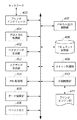
図5は、本実施形態に係るドキュメント合成時における画像処理装置の処理の手順を示すフローチャートである。リモートコピーとは、例えば、MFP1において読み取られた原稿画像をMFP2において印刷出力するように、従来のコピー動作におけるスキャン動作とプリント動作がネットワーク上の異なる機器で行われる処理をいう。一方、スキャン動作からプリント動作までが同一の装置において行われる処理をローカルコピーという。例えば、MFPのプリンタ機能が、他のジョブの印刷処理を実行しているためにローカルコピーを行うことの出来ない場合に、リモートコピー機能によって、プリント動作をネットワーク上の他の装置に代替処理させることができる。また、コピー出力を遠隔地にいるユーザに人手を介して配布する場合に、リモートコピー機能を用いて当該ユーザの近傍に設置されている装置に印刷出力することによって、配布にかかる工数を省くことができる。本実施形態において、スキャン動作を行う側のMFPをローカルMFPとし、印刷出力を行う側のMFPをリモートMFPとする。また、図5において、リモートコピーが実行され、ドキュメントがリモートMFPの記憶装置に格納され、ユーザが、格納されたドキュメントに対して合成、検索等の処理を行う。
FIG. 5 is a flowchart showing a processing procedure of the image processing apparatus at the time of document composition according to the present embodiment. Remote copy refers to a process in which a scanning operation and a printing operation in a conventional copying operation are performed by different devices on a network so that a document image read by the
図5に示すフローチャートは、ローカルMFPのコントロールユニット300のCPU305によって実行される。また、CPU305に制御されて、コントロールユニット300に示されるいずれかの機能ブロックにおいて実行されるようにしても良い。まず、ステップS501において、ユーザにより、ドキュメント(ファイル)の合成が指示される。次に、ステップS502において、リモートMFPの記憶装置に格納されている当該合成が指示されたファイルに関して重複するメタデータの制御が行われ、重複するメタデータが削除されるか、又は、検索対象外とされる。次に、ステップS503において、ドキュメント(ファイル)が合成され、新たに合成されたドキュメント(以下、合成ファイルともいう)として、記憶装置に格納される。
The flowchart shown in FIG. 5 is executed by the
このように本実施形態においては、ユーザにより、ドキュメントを合成するように指示された場合に、検索対象のメタデータが重複しないように処理され、その結果、記憶装置内のファイルの検索等において高速化を図ることができる。以下、詳細について説明する。 As described above, in the present embodiment, when a user instructs to synthesize a document, processing is performed so that metadata to be searched does not overlap, and as a result, search for a file in a storage device is performed at high speed. Can be achieved. Details will be described below.
図6は、ユーザが、リモートコピーを指示する場合に、ローカルMFPの操作部に表示される画面の一例を示す図である。画面601は、リモートコピーの設定および開始を行うために操作部に表示される画面であり、ユーザがリモートコピーモードボタン602を押下すると表示される。
FIG. 6 is a diagram illustrating an example of a screen displayed on the operation unit of the local MFP when the user instructs remote copying. A
ユーザは、プリンタ選択ボタン603を押下すると、リモートコピーの出力先として指定できるリモート装置のプルダウンリストが表示され(図示されていない)、所望のリモート機器を選択することができる。選択されたリモート装置の名称は、表示604に表示される。リモートコピーの出力先として指定できるリモート装置のリストは、あらかじめ装置内に保持されていても良い。また、ネットワークに接続された、指定可能なリモート装置のリストを管理するサーバ等から取得するようにしてもよい。また、リモートコピーを受付けることができる装置を検索するパケットをネットワーク上にブロードキャスト送信し、応答のあった装置をリスト化するようにしても良い。
When the user presses the
ボタン605は、リモートコピーを実行する際に、リモート装置のボックス(記憶部)に保存するか否かを選択するボックス保存選択ボタンである。本実施形態において、ボックス保存選択ボタンは、トグル制御になっていて、一回押下すると選択された状態になり、再度押下すると選択が解除された状態となる。
A
倍率指定ボタン606によって、リモートコピー時に、拡大縮小倍率を指定することができる。倍率指定ボタン606を押下することにより、不図示の倍率指定画面が表示され、ユーザは、画面上で拡大縮小倍率を指定することができる。また、倍率指定ボタン606の「等倍」を押下することにより、倍率指定画面を表示することなく、拡大縮小倍率100%を指定することができる。ユーザが指定した、拡大縮小倍率は表示領域607に表示される。
An enlargement / reduction ratio can be designated by a
用紙選択ボタン608によって、印刷出力を行う用紙を選択することができる。ユーザが用紙選択ボタン608を押下すると、印刷出力時に選択可能な用紙サイズのリストが表示される。印刷出力を行う用紙として選択された用紙サイズは、表示領域609に表示される。本実施形態においては、「AUTO」が選択されており、その結果、原稿のスキャン時に原稿サイズを検知すると共に、ユーザの指定した拡大縮小倍率を考慮し、最適な出力用紙が自動的に選択される。
A paper to be printed out can be selected by a
表示領域610には、リモートコピー時のコピー部数が表示される。コピー部数は、ユーザが、不図示のハードキーを操作することにより設定できる。フィニッシング設定ボタン611によって、フィニッシャ設定を行うことができる。フィニッシング設定ボタン611を押下することにより、不図示のフィニッシャ設定画面が表示され、ソートやステイプル、パンチャー等の印刷後の用紙に対する各種のフィニッシィングに関する設定を行うことできる。
A
両面指定ボタン612によって、両面コピーの指定を行うことができる。両面指定ボタン612を押下することにより、不図示の両面設定画面が表示され、両面、片面設定や、両面設定時の綴じ方向の設定等を行うことができる。応用機能設定ボタン613によって、応用機能設定を行うことができる。応用機能設定ボタン613を押下することにより、ページ連写、製本、縮小レイアウト設定等、MFPが有する高度な応用機能の設定を行うことができる。カラーモード設定ボタン614によって、カラーモードの設定を行うことができる。カラーモード設定ボタン614を押下することにより、「カラーコピー」、「モノクロコピー」、「AUTO」のリストが表示され、ユーザは、所望の項目を選択することができる。「カラーコピー」、「モノクロコピー」が選択されると、それぞれ選択されたモードでの印刷出力が行われる。一方、「AUTO」が選択されると、原稿がスキャンされた際に、原稿がカラー原稿であるか、又は、モノクロ原稿であるかが自動判定され、カラー原稿であればカラーコピーが実行され、モノクロ原稿であればモノクロコピーが実行される
図7は、ユーザが、画像出力装置の二次記憶装置(以下、ボックスともいう)に保存されたファイルの合成を指示する場合において、操作部の表示部に表示される画面の一例を示す図である。図7に示す表示701において、ボックス内に保存されたファイルが、一覧表示される。ボタン702は合成ボタンであり、ユーザが、表示701上において複数のファイルを選択し、ボタン702の合成ボタンを押下することによって、選択されたファイルが合成される。ボタン703は、検索ボタンである。ユーザが、ファイルの検索を所望する場合に、ボタン703を押下することによって、図示されていない、所望の文字列を入力する画面が表示される。その結果、入力された所望の文字列によりボックス内のファイルのメタデータが検索され、表示701に検索結果が表示される。
A
次に、本実施形態において、ベクタデータ、ディスプレイリスト、メタデータが含まれるドキュメントが構成される処理について説明する。 Next, in the present embodiment, a process for configuring a document including vector data, a display list, and metadata will be described.
図8は、スキャン動作時におけるドキュメントを生成する手順の全体概要を示す図である。スキャナ部11に配置された紙原稿は、スキャン処理d1によってビットマップデータに変換される。次に、ベクタライズ処理d2とメタデータ生成処理d4とによって、ビットマップデータから、解像度に依存しないベクタデータと、メタデータが生成される。即ち、例えば、ローカルMFPである画像処理装置は、解像度非依存であるベクタデータを生成する解像度非依存データ生成手段と、付加情報データであるメタデータを生成する付加情報データ生成手段を有している。
FIG. 8 is a diagram showing an overview of a procedure for generating a document during a scanning operation. The paper document placed on the
次に、ドキュメント生成処理d3によって、ベクタデータとメタデータが関連付けられたドキュメントが生成される。次に、ディスプレイリスト生成処理d5により、ドキュメントに含まれるベクタデータからディスプレイリストが生成される。即ち、例えば、ローカルMFPである画像処理装置は、解像度依存であるディスプレイリストを生成する解像度依存データ生成手段を有している。生成されたディスプレイリストは、ドキュメントに格納されると共に、レンダリング処理d7において、ビットマップデータに展開される。展開されたビットマップデータは印刷処理d8によって、紙媒体に記録されて印刷物とされる。ここで、出力された印刷物を、再度、スキャナ部11に配置すると、スキャン処理d1からの処理を、再度行うことができる。
Next, a document in which vector data and metadata are associated is generated by document generation processing d3. Next, a display list is generated from the vector data included in the document by display list generation processing d5. That is, for example, an image processing apparatus that is a local MFP has resolution-dependent data generation means for generating a display list that is resolution-dependent. The generated display list is stored in the document and developed into bitmap data in the rendering process d7. The developed bitmap data is recorded on a paper medium by the printing process d8 to be printed. Here, when the output printed matter is again arranged in the
図9は、図8におけるメタデータ生成処理d4の処理の手順を示すフローを示す図である。図9に示すように、領域分割処理d1において、ビットマップデータから領域分割が行われる。ここで、領域分割とは、入力されたビットマップ画像データを解析し、画像データに含まれるオブジェクト毎に領域分割し、各領域の属性を判定し、分類する処理をいう。属性としては、例えば、文字「TEXT」、画像「PHOTO」、線「LINE」、図形「PICTURE」、表「TABLE」が挙げられる。 FIG. 9 is a flowchart illustrating a processing procedure of the metadata generation processing d4 in FIG. As shown in FIG. 9, in the area division processing d1, area division is performed from bitmap data. Here, the area division refers to a process of analyzing input bitmap image data, dividing the area for each object included in the image data, determining the attribute of each area, and classifying. Examples of the attribute include a character “TEXT”, an image “PHOTO”, a line “LINE”, a figure “PICTURE”, and a table “TABLE”.
ここで、領域分割の一例について説明する。図10は、入力画像に対して領域分割を行った場合の一例を示す図である。入力画像91に対して領域分割を行った結果が、判定結果92である。判定結果92における点線で囲った部分が、画像を解析した結果、生成された1つのオブジェクト単位を表している。また、各オブジェクト単位に対して付されている属性の種類が、領域分割の判定結果である。
Here, an example of area division will be described. FIG. 10 is a diagram illustrating an example when region division is performed on an input image. A
属性毎に分類された領域において、文字属性で示される領域は、OCR処理d2により文字認識処理されて文字列に変換される。即ち、変換された文字列は、紙面に印字されている文字列である。また、属性毎に分類された領域において、画像属性で示される領域は、画像情報抽出処理d8によって、画像情報に変換される。ここで、画像情報とは画像の特徴を現す文字列であり、例えば、「花」や「顔」といった文字列を示す。画像情報の抽出において、画像を構成するピクセルの周波数や濃度等の画像特徴を検出する画像特徴検出や、顔認識等の一般的に知られる画像処理技術を用いても良い。生成された文字列と画像情報は、フォーマット変換処理d4によって、後述するデータフォーマットに整えられて、メタデータが生成される。 In the area classified for each attribute, the area indicated by the character attribute is subjected to character recognition processing by the OCR processing d2 and converted into a character string. That is, the converted character string is a character string printed on paper. In the region classified for each attribute, the region indicated by the image attribute is converted into image information by the image information extraction process d8. Here, the image information is a character string representing the characteristics of the image, and for example, indicates a character string such as “flower” or “face”. In the extraction of image information, generally known image processing techniques such as image feature detection for detecting image features such as the frequency and density of pixels constituting the image, and face recognition may be used. The generated character string and image information are arranged in a data format to be described later by the format conversion process d4, and metadata is generated.
図11は、PDLプリント時におけるドキュメントを生成する手順の全体概要を示す図である。PDLプリントとは、例えば、汎用PCに実装されたアプリケーションソフトから印刷を指示した場合に、プリンタドライバによって生成されたページ記述言語に基づいて出力するプリンタ動作をいう。本実施形態において、例えば、LIPS(LBP Image Processing System)(登録商標)や、PS(PostScript)(登録商標)が、PDLとして用いられる。 FIG. 11 is a diagram showing an overview of a procedure for generating a document during PDL printing. PDL printing refers to, for example, a printer operation that outputs based on a page description language generated by a printer driver when printing is instructed from application software installed on a general-purpose PC. In the present embodiment, for example, LIPS (LBP Image Processing System) (registered trademark) or PS (PostScript) (registered trademark) is used as the PDL.
図11に示すように、受信したPDLデータがPDLデータ解析処理d1において解析され、ベクタデータが生成される。次に、ディスプレイリスト生成処理d2において、ベクタデータからディスプレイリストが生成される。生成されたディスプレイリストは、レンダリング処理d3に送信され、ビットマップデータに展開される。展開されたビットマップデータは、印刷処理d4において、紙媒体に記録されて印刷物となる。また、図9において説明したように、レンダリング処理d3において、生成されたビットマップデータから、メタデータ生成処理d5により、文字列や画像情報がメタデータとして生成される。図11に示すフローにおいて、生成されたベクタデータ、ディスプレイリスト、メタデータは、ドキュメント生成処理d6において、ドキュメントに格納される。図11においてメタデータが生成される場合に、PDLが、文字列情報を有しているのであれば、PDLデータ解析時に、文字列情報からメタデータが生成されて、ドキュメントに格納されても良い。 As shown in FIG. 11, the received PDL data is analyzed in a PDL data analysis process d1, and vector data is generated. Next, in the display list generation process d2, a display list is generated from the vector data. The generated display list is transmitted to the rendering process d3 and developed into bitmap data. In the printing process d4, the developed bitmap data is recorded on a paper medium to become a printed matter. Further, as described in FIG. 9, in the rendering process d3, a character string and image information are generated as metadata from the generated bitmap data by the metadata generation process d5. In the flow shown in FIG. 11, the generated vector data, display list, and metadata are stored in the document in the document generation process d6. When the metadata is generated in FIG. 11, if the PDL has character string information, the metadata may be generated from the character string information and stored in the document at the time of PDL data analysis. .
図8及び図9において、ビットマップデータからベクタデータとメタデータを生成する手順を説明したが、実際には、ビットマップデータの領域の分割種別について、それぞれの処理が行われる場合がある。図12は、分割された領域種別について、ベクタデータとメタデータとが生成される手順を示す図である。 Although the procedure for generating vector data and metadata from bitmap data has been described with reference to FIGS. 8 and 9, each process may be actually performed for the division type of the bitmap data area. FIG. 12 is a diagram illustrating a procedure in which vector data and metadata are generated for the divided area types.
ステップS1101において、図9における説明と同様の領域分割の処理が行われる。ステップS1102において、領域の種別、即ち、属性が、「TEXT」、「GRAPHIC」、「IMAGE」に分類される。例えば、図10において分類されていた属性の内、「PHOTO」と「PICURE」は、「IMAGE」に分類され、「LINE」と「TABLE」は、「GRAPHIC」に分類される。ステップS1102において、領域の属性が「TEXT」である場合には、ステップS1103に進み、OCR処理が行われ、ステップS1104において、文字列が抽出される。更に、ステップS1105において、文字列がメタデータに変換され、ステップS1106において、文字輪郭がベクタデータに変換される。文字列から変換されたメタデータは、文字コードの羅列であり、本実施形態において、ファイルのキーワード検索等に用いられる。しかしながら、ステップS1103におけるOCR処理は、文字コードを認識することができるが、明朝体やゴシック体等の書体、10pt等の文字サイズ、イタリックやボールド等の文字修飾等を認識することができない。しかしながら、本実施形態においては、ステップS1106において、文字輪郭がベクタデータに変換されているので、描画する際に必要な情報を含むことができる。 In step S1101, the same region division processing as described in FIG. 9 is performed. In step S1102, the type of area, that is, the attribute is classified into “TEXT”, “GRAPHIC”, and “IMAGE”. For example, among the attributes classified in FIG. 10, “PHOTO” and “PICURE” are classified as “IMAGE”, and “LINE” and “TABLE” are classified as “GRAPHIC”. If the region attribute is “TEXT” in step S1102, the process proceeds to step S1103, where OCR processing is performed, and in step S1104, a character string is extracted. Further, in step S1105, the character string is converted into metadata, and in step S1106, the character outline is converted into vector data. The metadata converted from the character string is an enumeration of character codes, and is used for file keyword search or the like in this embodiment. However, although the OCR process in step S1103 can recognize the character code, it cannot recognize the font size such as Mincho type or Gothic type, character size such as 10 pt, character modification such as italic or bold. However, in this embodiment, since the character outline is converted into vector data in step S1106, information necessary for drawing can be included.
また、ステップS1102において、領域の属性が「IMAGE」である場合には、ステップS1107に進み、画像情報抽出処理が行われる。ステップS1107において、図9における説明と同様に、画像特徴量検出や顔認識等の一般的に知られる画像処理技術が用いられて、画像の特徴が検出される。次に、ステップS1108に進み、ステップS1107において検出された画像の特徴が、文字列に変換される。ここで、例えば、MFP1が、HDD308等に、特徴を示すパラメータと文字列との対応テーブルを、予め保持するようにしても良い。次に、ステップS1109において、文字列がメタデータに変換される。また、領域の属性が「IMAGE」である場合には、イメージデータが、そのままベクタデータとして保持される。また、ステップS1102において、領域の属性が「GRAPHIC」である場合には、ステップS1110に進み、ベクタライズ処理が行われる。
If the region attribute is “IMAGE” in step S1102, the process proceeds to step S1107, and image information extraction processing is performed. In step S1107, similar to the description in FIG. 9, image features are detected using generally known image processing techniques such as image feature amount detection and face recognition. Next, proceeding to step S1108, the image features detected at step S1107 are converted into a character string. Here, for example, the
本実施形態においては、ベクタデータ、ディスプレイリスト、メタデータを含んだドキュメントが生成され、リモートコピーにおいて、そのドキュメントが印刷される。以下に、本実施形態におけるドキュメントの印刷の手順について説明する。 In this embodiment, a document including vector data, a display list, and metadata is generated, and the document is printed in remote copy. Hereinafter, a procedure for printing a document in the present embodiment will be described.
図13は、生成されたドキュメントを印刷する処理の手順を示すフローチャートである。但し、図13においては、ローカルMFPからリモートMFPにデータが送信されるステップについては、示されていない。 FIG. 13 is a flowchart illustrating a processing procedure for printing a generated document. However, FIG. 13 does not show the step of transmitting data from the local MFP to the remote MFP.
ステップS1201において、印刷制御部410がビットマップデータから生成されたドキュメント(図8に示すドキュメント生成処理d3)を受け取り、ステップS1202においてドキュメントに含まれるベクタデータからディスプレイリストが生成される。次に、ステップS1203において、生成されたディスプレイリストが、ドキュメントに追加される。ステップS1204において、ドキュメントからディスプレイリストが抽出され、ディスプレイリストがビットマップデータにレンダリングされる。最後に、ステップS1205において、レンダリングされたデータ(出力データ)の紙媒体への印刷処理が行われる。
In step S1201, the
図14は、PDLプリント時における、生成されたドキュメントを印刷処理の手順を示すフローチャートである。但し、図13の場合と同様に、図14においても、ローカルMFPからリモートMFPにデータが送信されるステップについては、示されていない。 FIG. 14 is a flowchart showing a procedure for printing a generated document during PDL printing. However, as in FIG. 13, FIG. 14 does not show the step of transmitting data from the local MFP to the remote MFP.
ステップS1301において、PDLデータが解析され、文字列情報等のメタデータが含まれているのであれば、別処理において、そのメタデータがドキュメントに追加される。ステップS1303において、メタデータ以外のデータが、ベクタデータに変換され、ステップS1304において、ドキュメントが生成される。次に、ステップS1305において、ベクタデータからディスプレイリストが生成され、ステップS1306において、生成されたディスプレイリストがドキュメントに追加される。ステップS1307において、ドキュメントからディスプレイリストが抽出され、ディスプレイリストがレンダリングされてビットマップデータに展開される。最後に、ステップS1308において、レンダリングされたデータ(出力データ)の紙媒体への印刷処理が行われる。 In step S1301, if the PDL data is analyzed and metadata such as character string information is included, the metadata is added to the document in a separate process. In step S1303, data other than metadata is converted into vector data, and in step S1304, a document is generated. Next, in step S1305, a display list is generated from the vector data, and in step S1306, the generated display list is added to the document. In step S1307, a display list is extracted from the document, and the display list is rendered and developed into bitmap data. Finally, in step S1308, the rendered data (output data) is printed on a paper medium.
次に、本実施形態において生成されるドキュメントのフォーマットについて説明する。 Next, the format of a document generated in this embodiment will be described.
図15は、ドキュメントのデータ構造を示す図である。図15に示すように、ドキュメントは、ベクタデータと、メタデータと、ディスプレイリストとを含んでいて、それぞれが複数のページを有している。また、図15に示すように、ドキュメントは、ドキュメントヘッダ1401を上位として、階層構造とされている。ベクタデータとディスプレイリストは、それぞれ、ページヘッダ1402及び1407を有していて、ドキュメントヘッダ1401の下位に位置している。ドキュメントヘッダ1401には、ベクタデータ及びディスプレイリストのメモリ等への格納場所が記述されているので、ベクタデータとディスプレイリストは、ドキュメントヘッダ1401を介して、相互に関連付けられている。ベクタデータにおいては、複数のページヘッダ1402のそれぞれの下位に、サマリ1403が構成されている。ベクタデータは、プリンタエンジンの解像度に非依存の描画データであり、ページヘッダ1402には、ページの大きさ、向き等のレイアウト情報が記述されている。また、図15に示すように、複数のサマリが関連付けられているが、それぞれのサマリの下位に、オブジェクト1404が構成されている。オブジェクト1404には、ライン、多角形、ベジェ曲線などの描画データが一つずつリンクされていて、複数のオブジェクトが、まとめてサマリ1403に関連付けられている。サマリ1403には、複数のオブジェクトの特徴をまとめた情報が記述されていて、例えば、図10において説明した分割領域の属性情報等が記述されている。
FIG. 15 is a diagram illustrating a data structure of a document. As shown in FIG. 15, the document includes vector data, metadata, and a display list, each having a plurality of pages. Further, as shown in FIG. 15, the document has a hierarchical structure with the
図15に示すメタデータとは、描画処理には関係せず、例えば、ファイル検索用の付加情報として用いられる。図15に示すように、メタデータは、ページ情報1405及び詳細情報1406で構成される情報を、複数有している。本実施形態において、ページ情報1405には、例えば、メタデータがビットマップデータ又はPDLデータから生成された情報が記述されていて、詳細情報1406には、例えば、OCR情報や画像情報として生成された文字コード列が記述されている。本実施形態においては、ベクタデータのサマリ1403から、メタデータの対応するページ情報1405の詳細情報1406を参照することができる。
The metadata shown in FIG. 15 is not related to the drawing process and is used as additional information for file search, for example. As shown in FIG. 15, the metadata has a plurality of pieces of information including
図15に示すディスプレイリストとは、レンダラがビットマップデータに展開する際に用いられる中間コードである。図15に示すように、ディスプレイリストは、ページヘッダ1407及び描画展開用のインストラクション1408から構成されている。本実施形態において、ページヘッダ1407には、そのページ内の描画情報(インストラクション)の管理テーブル等が記述されていて、インストラクション1408は、プリンタエンジンの解像度に依存するインストラクションで構成されている。
The display list shown in FIG. 15 is an intermediate code used when the renderer develops bitmap data. As shown in FIG. 15, the display list includes a
図16は、ドキュメントのデータ構成の一例を示す図である。図16に示すように、1ページ目を示すページヘッダ1501は、属性情報「TEXT」を有するサマリ1502と、属性情報「IMAGE」を有するサマリ1503とを含んでいる。また、サマリ1502に関連付けられるオブジェクト1504には、「Hello」の各文字の文字輪郭を示すベクタデータがリンクされている。オブジェクト1505には、「World」の各文字の文字輪郭を示すベクタデータがリンクされている。また、サマリ1503に関連付けられるオブジェクト1506には、例えば、JPEG形式の蝶の写真画像がリンクされている。サマリ1502は、メタデータの詳細情報の領域1507に含まれている文字コード列を参照していて、サマリ1503は、メタデータの詳細情報の領域1508に含まれている「butterfly」という画像情報を参照している。本実施形態において、例えば、「World」というキーワードによって、ページ中のテキストが検索される場合には、メタデータの詳細情報における領域1507が参照される。
FIG. 16 is a diagram illustrating an example of a data structure of a document. As shown in FIG. 16, the
図17は、図15に示すドキュメントが、メモリ又はファイル上に配置される一例を示す図である。図17の(a)は、図15に示すドキュメントが、メモリ上のアドレスに配置される一例を示す図である。図17の(a)に示すように、ドキュメントはベクタデータ領域、メタデータ領域、ディスプレイリスト領域が、メモリ上の任意のアドレスに配置されている。矢印1601、矢印1602、矢印1603は、図16において説明したような、ベクタデータからメタデータが参照されることを示している。図17の(b)に示すように、ベクタデータ領域、メタデータ領域、ディスプレイリスト領域が、一つのファイルにシリアライズされている。図17の(a)においては、ベクタデータからメタデータは、ポインタにより参照されているが、図17の(b)においては、ベクタデータからメタデータは、オフセット情報により参照されている。
FIG. 17 is a diagram illustrating an example in which the document illustrated in FIG. 15 is arranged on a memory or a file. FIG. 17A shows an example in which the document shown in FIG. 15 is arranged at an address on the memory. As shown in FIG. 17A, in the document, a vector data area, a metadata area, and a display list area are arranged at arbitrary addresses on the memory. An
再び、本実施形態に係る動作について説明する。図5に示すステップS502において、図19又は図20のような制御が行われる。図18は、本実施形態に係るメタデータの重複の制御を説明する図である。図18に示すように、以下、リモートMFPの記憶装置に格納されているドキュメントAとドキュメントBを合成する場合について説明する。ドキュメントAとドキュメントBは、それぞれ、「Hello」、「World」というテキストを属性情報として有するサマリと、蝶のイメージデータを属性情報として有するサマリとを含むベクタデータを有している。また、ドキュメントA及びドキュメントBは、それぞれ、同一の内容のメタデータ1801、メタデータ1802を有している。
The operation according to this embodiment will be described again. In step S502 shown in FIG. 5, the control as shown in FIG. 19 or 20 is performed. FIG. 18 is a diagram for explaining control of metadata duplication according to the present embodiment. As shown in FIG. 18, a case where the document A and the document B stored in the storage device of the remote MFP are combined will be described below. The document A and the document B each have vector data including a summary having texts “Hello” and “World” as attribute information and a summary having butterfly image data as attribute information. Document A and document B have
図19は、本実施形態において、検索対象フラグが用いられる場合を説明する図である。図19に示すように、フラグ1901及び1902は、メタデータに付加される検索対象フラグである。図19においては、フラグ1902がオフと設定されている。その結果、重複するドキュメントBのメタデータが検索対象外とされ、例えばローカルMFPのCPU305はメタデータ1802に対して検索処理を行わない。また、フラグ1901はオンと設定されているので、メタデータ1801に対しては、検索処理を行う。
FIG. 19 is a diagram illustrating a case where a search target flag is used in the present embodiment. As shown in FIG. 19,
図20は、本実施形態において、重複するメタデータが削除される場合を説明する図である。図20に示すように、重複するドキュメントBのメタデータ1802が、ドキュメントBから削除されていて、ドキュメントBは、ドキュメントAのメタデータを参照するように変更されている。その結果、ドキュメントAとドキュメントBが合成された図20に示すドキュメントは、メタデータ1801のみを有しているので、検索処理もメタデータ1801に対してのみ行われる。
FIG. 20 is a diagram illustrating a case where duplicate metadata is deleted in the present embodiment. As shown in FIG. 20, the duplicate
図21は、図5における重複メタデータ制御処理の手順を示すフローチャートである。まず、ステップS2101において、例えば、ローカルMFPのCPU305は、合成される両方のドキュメントのメタデータを検索する。次に、ステップS2102において、検索されたメタデータについて、重複の有無が判定される。即ち、本実施形態に係る画像処理装置は、それぞれの付加情報データを参照し、一致しているか否かを判定する一致判定手段を有している。ここで、重複が無しと判定された場合には、本フローチャートを終了し、通常のドキュメントの合成処理が行われる。一方、重複が有りと判定された場合には、ステップS2103に進み、基準となるデータサイズの閾値が算出される。データサイズの閾値については後述する。ステップS2104において、合成されたドキュメントのデータサイズが検出され、ステップS2105において、合成されたドキュメントのデータサイズが、データサイズの閾値以上であるか、閾値未満であるかが判定される。即ち、本実施形態に係る画像処理装置は、ドキュメントのデータサイズと、閾値を示すデータサイズとを比較するサイズ判定手段を有している。ここで、ドキュメントのデータサイズが、閾値以上である場合には、ステップS2106に進み、重複するメタデータが削除される。一方、データサイズが、閾値未満である場合には、ステップS2107に進み、重複するメタデータのいずれか一方に検索対象外を示すフラグを付加する。その場合に、重複するメタデータの内、他の一方には、検索対象を示すフラグを付加する。そのようなメタデータに対してフラグを付加する処理(フラグ付加手段)は、ローカルMFPのCPU305が、例えば、RAM306上で行っても良い。また、検索対象を示すフラグを「1」で示し、検索対象外を示すフラグを「0」で示すようにしても良いし、他の方法が用いられても良い。
FIG. 21 is a flowchart showing the procedure of the duplicate metadata control process in FIG. First, in step S2101, for example, the
従って、本実施形態において、合成後のドキュメントのサイズ、即ち、合成サイズが、閾値となるデータサイズ、即ち、基準サイズ以上であれば、重複するメタデータを削除する。一方、合成サイズが、基準サイズ未満であれば、ドキュメントのサイズが十分に小さいと判断し、重複するメタデータは削除せず、フラグを付加することによって検索処理の対象外とする。このように、本実施形態では、ドキュメントを合成した際に、重複するメタデータを削除または検索対象フラグをオフにするので、検索の高速化を図ることができる。 Therefore, in the present embodiment, if the size of the combined document, that is, the combined size is equal to or larger than the threshold data size, that is, the reference size, duplicate metadata is deleted. On the other hand, if the combined size is less than the reference size, it is determined that the document size is sufficiently small, and the duplicate metadata is not deleted, and is excluded from the search processing target by adding a flag. As described above, in the present embodiment, when documents are combined, duplicate metadata is deleted or the search target flag is turned off, so that the search speed can be increased.
図22は、サイズ閾値算出処理の手順を示すフローチャートである。既に説明したように、本実施形態においては、閾値となるデータサイズが、算出される。まず、ステップS2201において、画像処理装置が接続されているネットワークインターフェイスの転送レートが算出される。本実施形態において、例えば、ネットワークインターフェイスが、例えば、汎用のNIC(Network Interface Card)等のハードウェアで構成されている場合には、そのハードウェアの性能値から転送レートを取得しても良い。また、ネットワークインターフェイスが、ソフトウェアで構成されている場合には、CPUの性能から転送レートを算出しても良い。 FIG. 22 is a flowchart illustrating the procedure of the size threshold calculation process. As already described, in this embodiment, the data size serving as the threshold is calculated. First, in step S2201, the transfer rate of the network interface to which the image processing apparatus is connected is calculated. In the present embodiment, for example, when the network interface is configured by hardware such as a general-purpose NIC (Network Interface Card), the transfer rate may be acquired from the performance value of the hardware. If the network interface is configured by software, the transfer rate may be calculated from the performance of the CPU.
次に、ステップS2202において、プリンタエンジン速度(以下、エンジン速度とする)が取得され、ステップS2203に進む。ステップS2203において、そのエンジン速度によって、転送、受信が可能なドキュメントサイズが算出される。本実施形態において、ドキュメントサイズDmaxは、次式(1)によって求められる。 In step S2202, a printer engine speed (hereinafter referred to as engine speed) is acquired, and the process advances to step S2203. In step S2203, a document size that can be transferred and received is calculated based on the engine speed. In the present embodiment, the document size Dmax is obtained by the following equation (1).
Dmax = Tr×60/Es ・・・(1)
式(1)において、Trは、「MB/sec」を単位として表される、単位時間当りに転送可能なファイルサイズを表す転送レートを示している。Esは、「page/min」を単位として表される、単位時間当たりに転送可能なページ数を示すエンジン速度を示している。従って、式(1)によって、1ページ当りのデータサイズで示されるドキュメントサイズDmaxが求められる。
Dmax = Tr × 60 / Es (1)
In the formula (1), Tr represents a transfer rate that represents a file size that can be transferred per unit time and is expressed in units of “MB / sec”. Es indicates an engine speed indicating the number of pages that can be transferred per unit time, expressed in units of “page / min”. Therefore, the document size Dmax indicated by the data size per page is obtained by the equation (1).
図23は、サイズ閾値算出処理の他の手順を示すフローチャートである。本例においては、ドキュメントが保存される記憶装置における未使用の容量を、閾値となるデータサイズとして決定する。まず、ステップS2301において、ドキュメントが保存されるハードディスク等の記憶装置における残り容量(未使用の空きディスク容量)が検出される。次に、ステップS2302において、残りディスク容量自体を閾値として決定する。本例においては、ドキュメントが保存されるハードディスクが圧迫されるまで、重複するメタデータの削除処理は行われない。従って、メタデータが削除される処理がされていないので、合成されたファイルを分離する場合において、重複メタデータを復帰させる処理を行う必要がない。 FIG. 23 is a flowchart illustrating another procedure of the size threshold calculation process. In this example, the unused capacity in the storage device in which the document is stored is determined as the data size serving as a threshold value. First, in step S2301, the remaining capacity (unused free disk capacity) in a storage device such as a hard disk in which a document is stored is detected. Next, in step S2302, the remaining disk capacity itself is determined as a threshold value. In this example, the process of deleting duplicate metadata is not performed until the hard disk in which the document is stored is compressed. Accordingly, since the process for deleting the metadata is not performed, it is not necessary to perform the process for restoring the duplicate metadata when the synthesized file is separated.
本発明には、プログラム(画像処理プログラム)コードの指示に基づき、コンピュータ上で稼働しているオペレーティングシステム(OS)などが実際の処理の一部または全部を行い、その処理によって前述した実施形態の機能が実現される場合も含まれる。さらに、記憶媒体から読み出されたプログラムコードが、コンピュータに挿入された機能拡張カードやコンピュータに接続された機能拡張ユニットに備わるメモリに書込まれた場合についても、本発明は適用される。その場合、書き込まれたプログラムコードの指示に基づき、その機能拡張カードや機能拡張ユニットに備わるCPUなどが実際の処理の一部または全部を行い、その処理によって前述した実施形態の機能が実現される。 In the present invention, an operating system (OS) operating on a computer performs part or all of actual processing based on an instruction of a program (image processing program) code, and the processing of the above-described embodiment is performed by the processing. This includes cases where functions are realized. Furthermore, the present invention is also applied to the case where the program code read from the storage medium is written into a memory provided in a function expansion card inserted into the computer or a function expansion unit connected to the computer. In that case, the CPU of the function expansion card or function expansion unit performs part or all of the actual processing based on the instruction of the written program code, and the functions of the above-described embodiments are realized by the processing. .
また、本発明は、複数の機器から構成されるシステムに適用されても良いし、また、例えば、スキャナ、プリンタ、PC、複写機、複合機及びファクシミリ装置のような一つの機器からなる装置に適用されても良い。本発明は、前述した実施形態の各機能を実現するソフトウェアプログラムを、システム若しくは装置に対して直接または遠隔から供給し、そのシステム等に含まれるコンピュータが、該供給されたプログラムコードを読み出して実行することによっても達成される。従って、本発明の機能、処理をコンピュータで実現するために、該コンピュータにインストールされるプログラムコード自体によって、本発明が実現されても良い。即ち、上記の機能、処理を実現するためのコンピュータプログラム自体も本発明に含まれる。その場合、プログラムの機能を有していれば、オブジェクトコード、インタプリタにより実行されるプログラム、OSに供給するスクリプトデータ等の形態とされても良い。また、プログラムを供給するための記録媒体として、例えば、フレキシブルディスク、ハードディスク、光ディスク、光磁気ディスク、MO、CD−ROM、CD−R、CD−RW等が用いられても良い。更に、記録媒体として、磁気テープ、不揮発性のメモリカード、ROM、DVD(DVD−ROM、DVD−R)等が用いられても良い。 Further, the present invention may be applied to a system constituted by a plurality of devices, and for example, to an apparatus comprising a single device such as a scanner, a printer, a PC, a copier, a multifunction peripheral, and a facsimile machine. May be applied. The present invention supplies a software program that implements the functions of the above-described embodiments directly or remotely to a system or apparatus, and a computer included in the system reads and executes the supplied program code. Is also achieved. Therefore, in order to realize the functions and processes of the present invention by a computer, the present invention may be realized by program code itself installed in the computer. That is, the present invention includes a computer program for realizing the above functions and processes. In that case, as long as it has the function of a program, it may be in the form of object code, a program executed by an interpreter, script data supplied to the OS, and the like. As a recording medium for supplying the program, for example, a flexible disk, a hard disk, an optical disk, a magneto-optical disk, MO, CD-ROM, CD-R, CD-RW, or the like may be used. Further, a magnetic tape, a nonvolatile memory card, ROM, DVD (DVD-ROM, DVD-R), or the like may be used as a recording medium.
また、プログラムは、クライアントコンピュータのブラウザを用いてインターネット/イントラネットのウェブサイトからダウンロードされるようにしても良い。即ち、該ウェブサイトから、本発明のコンピュータプログラム自体、又は、圧縮されて自動インストール機能を含むファイルとして、ハードディスク等の記録媒体にダウンロードされても良い。また、本発明のプログラムを構成するプログラムコードが複数のファイルに分割され、それぞれのファイルが異なるウェブサイトからダウンロードされるようにしても良い。つまり、本発明の機能処理をコンピュータで実現するためのプログラムファイルが、WWW(World Wide Web)サーバによって複数のユーザに対してダウンロードされても良い。また、本発明のプログラムが暗号化され、CD−ROM等の記憶媒体に格納され、ユーザに配布されても良い。その場合に、所定条件をクリアしたユーザにのみ、ネットワークを介してウェブサイトから暗号化を解く鍵情報をダウンロードし、鍵情報によって暗号化されたプログラムを復号して実行し、プログラムをコンピュータにインストールするようにしてもよい。また、コンピュータが、読み出したプログラムを実行することによって、本発明の実施形態の機能が実現されてもよい。
The program may be downloaded from an Internet / intranet website using a browser of a client computer. That is, the computer program itself of the present invention or a compressed file including an automatic installation function may be downloaded from the website onto a recording medium such as a hard disk. The program code constituting the program of the present invention may be divided into a plurality of files, and each file may be downloaded from a different website. That is, a program file for realizing the functional processing of the present invention on a computer may be downloaded to a plurality of users by a WWW (World Wide Web) server. The program of the present invention may be encrypted, stored in a storage medium such as a CD-ROM, and distributed to users. In that case, only the user who cleared the predetermined condition downloads the key information to be decrypted from the website via the network, decrypts and executes the program encrypted by the key information, and installs the program in the computer You may make it do. Further, the functions of the embodiments of the present invention may be realized by a computer executing a read program.
1、2、3 MFP
11 スキャナ部
12 レーザ露光部
13 作像部
14 定着部
15 給紙搬送部
300 コントロールユニット
301 スキャナ
302 プリンタエンジン
305 CPU
306 RAM
307 ROM
308 HDD
309 操作部インタフェース
311 ネットワークインタフェース
312 モデム
313 システムバス
314 イメージバスインタフェース
315 画像バス
316 ラスタイメージプロセッサ
317 デバイスインタフェース
318 スキャナ画像処理部
319 プリンタ画像処理部
320 画像編集用画像処理部
330 カラーマネジメントモジュール
400 プリンタインタフェース
401 プロトコル制御部
402 ベクタデータ生成部
403 メタデータ生成部
404 PDL解析部
405 データ描画部
406 ページメモリ
407 パネル入出力制御部
408 ドキュメント記憶部
409 スキャン制御部
410 印刷制御部
411 プリンタエンジン部
1, 2, 3 MFP
DESCRIPTION OF
306 RAM
307 ROM
308 HDD
309
Claims (9)
ユーザの操作によって、前記ファイルと、前記ファイルとは異なる他のファイルとを合成するように指示された場合に、前記ファイルと前記他のファイルとに含まれるそれぞれの付加情報データを参照し、一致する付加情報データがあるか否かを判定する一致判定手段と、
前記一致判定手段によって、前記一致する付加情報データがあると判定された場合に、前記ファイルと前記他のファイルとを合成した合成サイズと、基準サイズとを比較するサイズ判定手段と、
前記サイズ判定手段によって、前記合成サイズが前記基準サイズ未満であると判定された場合に、前記ファイル又は前記他のファイルのいずれか一方に含まれる前記一致する付加情報データに、検索対象外であることを示すフラグを付加するフラグ付加手段と、
前記サイズ判定手段によって、前記合成サイズが前記基準サイズ以上であると判定された場合に、前記ファイル又は前記他のファイルのいずれか一方に含まれる前記一致する付加情報データを削除する削除手段と、
前記フラグ付加手段、又は、前記削除手段の結果、新たに生成された合成ファイルを、前記記憶領域に格納する格納手段と、
を備えることを特徴とする画像処理装置。 An image processing apparatus for storing a file in a storage area,
When it is instructed by the user's operation to synthesize the file and another file different from the file, the respective additional information data included in the file and the other file are referred to and matched. Match determination means for determining whether there is additional information data to be performed;
A size determination unit that compares a combined size obtained by combining the file and the other file with a reference size when the match determination unit determines that the matching additional information data exists;
When the size determination means determines that the combined size is less than the reference size, the matching additional information data included in either the file or the other file is not subject to search. Flag adding means for adding a flag indicating that;
A deletion unit that deletes the matching additional information data included in either the file or the other file when the size determination unit determines that the combined size is equal to or larger than the reference size;
Storage means for storing a newly generated composite file in the storage area as a result of the flag adding means or the deleting means;
An image processing apparatus comprising:
更に備えることを特徴とする請求項1乃至4のいずれか1項記載の画像処理装置。 Additional information data generating means for generating additional information data added as additional information to the input data and used for searching the input data from the input data,
The image processing apparatus according to claim 1, further comprising:
前記解像度非依存データ生成手段によって生成された前記解像度非依存データから、解像度に依存しビットマップデータに描画展開するために用いられる解像度依存データを生成する解像度依存データ生成手段と、
前記解像度非依存データ生成手段によって生成された前記解像度非依存データと、前記付加情報データ生成手段によって生成された前記付加情報データと、前記解像度依存データ生成手段によって生成された前記解像度依存データとを関連付け、前記ファイルとして前記記憶領域に保存する保存手段と、
を、更に備えることを特徴とする請求項5記載の画像処理装置。 Resolution-independent data generating means for generating resolution-independent data independent of resolution from the input data;
Resolution-dependent data generating means for generating resolution-dependent data used for rendering and rendering bitmap data depending on the resolution from the resolution-independent data generated by the resolution-independent data generating means;
The resolution-independent data generated by the resolution-independent data generating unit, the additional information data generated by the additional information data generating unit, and the resolution-dependent data generated by the resolution-dependent data generating unit. Associating and storing means for storing in the storage area as the file;
The image processing apparatus according to claim 5, further comprising:
前記画像処理装置は、リモートコピーの指示に応じて、入力データに基づいて、前記外部の画像出力装置の記憶領域に前記ファイルを格納する、
ことを特徴とする請求項1記載の画像処理装置。 The storage area is a storage area of an external image output device,
The image processing device stores the file in a storage area of the external image output device based on input data in response to a remote copy instruction.
The image processing apparatus according to claim 1.
一致判定手段が、ユーザの操作によって、前記ファイルと、前記ファイルとは異なる他のファイルとを合成するように指示された場合に、前記ファイルと前記他のファイルとに含まれるそれぞれの付加情報データを参照し、一致する付加情報データがあるか否かを判定する一致判定工程と、
サイズ判定手段が、前記一致判定工程によって、前記一致する付加情報データがあると判定された場合に、前記ファイルと前記他のファイルとを合成した合成サイズと、基準サイズとを比較するサイズ判定工程と、
フラグ付加手段が、前記サイズ判定工程によって、前記合成サイズが前記基準サイズ未満であると判定された場合に、前記ファイル又は前記他のファイルのいずれか一方に含まれる前記一致する付加情報データに、検索対象外であることを示すフラグを付加するフラグ付加工程と、
削除手段が、前記サイズ判定工程によって、前記合成サイズが前記基準サイズ以上であると判定された場合に、前記ファイル又は前記他のファイルのいずれか一方に含まれる前記一致する付加情報データを削除する削除工程と、
格納手段が、前記フラグ付加工程、又は、前記削除工程の結果、新たに生成された合成ファイルを、前記記憶領域に格納する格納工程と、
を備えることを特徴とする画像処理方法。 An image processing method for storing a file in a storage area,
When the match determination unit is instructed by the user's operation to combine the file with another file different from the file, each additional information data included in the file and the other file A match determination step for determining whether there is additional information data that matches,
A size determination step in which a size determination unit compares a combined size obtained by combining the file and the other file with a reference size when it is determined by the match determination step that there is the matching additional information data. When,
When the flag adding means determines that the combined size is less than the reference size by the size determining step, the matching additional information data included in either one of the file or the other file, A flag addition step of adding a flag indicating that the search is not performed;
When the size determining step determines that the combined size is equal to or larger than the reference size, a deleting unit deletes the matching additional information data included in either the file or the other file. Delete process,
A storage step of storing a newly generated composite file in the storage area as a result of the flag addition step or the deletion step;
An image processing method comprising:
ユーザの操作によって、前記ファイルと、前記ファイルとは異なる他のファイルとを合成するように指示された場合に、前記ファイルと前記他のファイルとに含まれるそれぞれの付加情報データを参照し、一致する付加情報データがあるか否かを判定する一致判定手段と、
前記一致判定手段によって、前記一致する付加情報データがあると判定された場合に、前記ファイルと前記他のファイルとを合成した合成サイズと、基準サイズとを比較するサイズ判定手段と、
前記サイズ判定手段によって、前記合成サイズが前記基準サイズ未満であると判定された場合に、前記ファイル又は前記他のファイルのいずれか一方に含まれる前記一致する付加情報データに、検索対象外であることを示すフラグを付加するフラグ付加手段と、
前記サイズ判定手段によって、前記合成サイズが前記基準サイズ以上であると判定された場合に、前記ファイル又は前記他のファイルのいずれか一方に含まれる前記一致する付加情報データを削除する削除手段と、
前記フラグ付加手段、又は、前記削除手段の結果、新たに生成された合成ファイルを、前記記憶領域に格納する格納手段と、
してコンピュータを機能させるための画像処理プログラム。 An image processing program for storing a file in a storage area,
When it is instructed by the user's operation to synthesize the file and another file different from the file, the respective additional information data included in the file and the other file are referred to and matched. Match determination means for determining whether there is additional information data to be performed;
A size determination unit that compares a combined size obtained by combining the file and the other file with a reference size when the match determination unit determines that the matching additional information data exists;
When the size determination means determines that the combined size is less than the reference size, the matching additional information data included in either the file or the other file is not subject to search. Flag adding means for adding a flag indicating that;
A deletion unit that deletes the matching additional information data included in either the file or the other file when the size determination unit determines that the combined size is equal to or larger than the reference size;
Storage means for storing a newly generated composite file in the storage area as a result of the flag adding means or the deleting means;
An image processing program for causing a computer to function.
Priority Applications (2)
| Application Number | Priority Date | Filing Date | Title |
|---|---|---|---|
| JP2007184655A JP4892427B2 (en) | 2007-07-13 | 2007-07-13 | Image processing apparatus, image processing method, and image processing program |
| US12/170,840 US8185504B2 (en) | 2007-07-13 | 2008-07-10 | Image processing apparatus and image processing method |
Applications Claiming Priority (1)
| Application Number | Priority Date | Filing Date | Title |
|---|---|---|---|
| JP2007184655A JP4892427B2 (en) | 2007-07-13 | 2007-07-13 | Image processing apparatus, image processing method, and image processing program |
Publications (3)
| Publication Number | Publication Date |
|---|---|
| JP2009021946A JP2009021946A (en) | 2009-01-29 |
| JP2009021946A5 JP2009021946A5 (en) | 2010-08-26 |
| JP4892427B2 true JP4892427B2 (en) | 2012-03-07 |
Family
ID=40254003
Family Applications (1)
| Application Number | Title | Priority Date | Filing Date |
|---|---|---|---|
| JP2007184655A Expired - Fee Related JP4892427B2 (en) | 2007-07-13 | 2007-07-13 | Image processing apparatus, image processing method, and image processing program |
Country Status (2)
| Country | Link |
|---|---|
| US (1) | US8185504B2 (en) |
| JP (1) | JP4892427B2 (en) |
Families Citing this family (8)
| Publication number | Priority date | Publication date | Assignee | Title |
|---|---|---|---|---|
| EP2480964A1 (en) * | 2009-09-25 | 2012-08-01 | OCE-Technologies B.V. | Method of creating a printable raster image file |
| US11016938B2 (en) | 2010-09-01 | 2021-05-25 | Apple Inc. | Consolidating information relating to duplicate images |
| US8774561B2 (en) | 2010-09-01 | 2014-07-08 | Apple Inc. | Consolidating information relating to duplicate images |
| US9535913B2 (en) * | 2013-03-08 | 2017-01-03 | Konica Minolta Laboratory U.S.A., Inc. | Method and system for file conversion |
| JP6281528B2 (en) * | 2015-06-11 | 2018-02-21 | 京セラドキュメントソリューションズ株式会社 | Information processing apparatus and information processing program |
| US11755758B1 (en) * | 2017-10-30 | 2023-09-12 | Amazon Technologies, Inc. | System and method for evaluating data files |
| US11768804B2 (en) * | 2018-03-29 | 2023-09-26 | Konica Minolta Business Solutions U.S.A., Inc. | Deep search embedding of inferred document characteristics |
| JP2021103846A (en) * | 2019-12-25 | 2021-07-15 | キヤノン株式会社 | Information processing apparatus, information processing system, information processing method, and program |
Family Cites Families (9)
| Publication number | Priority date | Publication date | Assignee | Title |
|---|---|---|---|---|
| US5532839A (en) * | 1994-10-07 | 1996-07-02 | Xerox Corporation | Simplified document handler job recovery system with reduced memory duplicate scanned image detection |
| JP3580060B2 (en) | 1996-05-09 | 2004-10-20 | 富士ゼロックス株式会社 | Print control apparatus and method |
| JP2000194712A (en) * | 1998-12-25 | 2000-07-14 | Fujitsu Ltd | Data processor and recording medium |
| US7003551B2 (en) * | 2000-11-30 | 2006-02-21 | Bellsouth Intellectual Property Corp. | Method and apparatus for minimizing storage of common attachment files in an e-mail communications server |
| JP4186678B2 (en) * | 2003-04-02 | 2008-11-26 | セイコーエプソン株式会社 | Print job management apparatus, program used therefor, and print job management method |
| JP4227569B2 (en) | 2004-07-07 | 2009-02-18 | キヤノン株式会社 | Image processing system, control method for image processing apparatus, program, and recording medium |
| US7809695B2 (en) * | 2004-08-23 | 2010-10-05 | Thomson Reuters Global Resources | Information retrieval systems with duplicate document detection and presentation functions |
| JP2008153820A (en) * | 2006-12-15 | 2008-07-03 | Brother Ind Ltd | Method and system for synthetic printing, printing apparatus, and program |
| US7676501B2 (en) * | 2008-03-22 | 2010-03-09 | Wilson Kelce S | Document integrity verification |
-
2007
- 2007-07-13 JP JP2007184655A patent/JP4892427B2/en not_active Expired - Fee Related
-
2008
- 2008-07-10 US US12/170,840 patent/US8185504B2/en not_active Expired - Fee Related
Also Published As
| Publication number | Publication date |
|---|---|
| US8185504B2 (en) | 2012-05-22 |
| US20090019074A1 (en) | 2009-01-15 |
| JP2009021946A (en) | 2009-01-29 |
Similar Documents
| Publication | Publication Date | Title |
|---|---|---|
| JP4928373B2 (en) | Image processing apparatus, image processing method, and image processing program | |
| JP4892427B2 (en) | Image processing apparatus, image processing method, and image processing program | |
| JP5038229B2 (en) | Image processing apparatus, image processing method, image processing program, and recording medium for recording the same | |
| JP5043715B2 (en) | Image processing device | |
| US8255832B2 (en) | Image processing device, image processing method, and storage medium | |
| US20080180707A1 (en) | Image processing apparatus, image processing system, and image processing method | |
| JP5084606B2 (en) | Image processing apparatus, control method therefor, and program | |
| JP5188201B2 (en) | Image processing apparatus, control method therefor, program, and storage medium | |
| US8259330B2 (en) | Output efficiency of printer forming image by interpreting PDL and performing output by using print engine | |
| JP5426843B2 (en) | Information processing apparatus, information processing method, program, and storage medium for storing program | |
| JP5258313B2 (en) | Image processing system, image processing method, and program | |
| US20090174898A1 (en) | plurality of image processing in image processing system having one or more network-connected image processing apparatuses | |
| US20070247653A1 (en) | Image processing apparatus and image processing method | |
| US20090284769A1 (en) | Image processing apparatus, image processing method, and program to execute image processing method | |
| US8259313B2 (en) | Image processing apparatus, method, and computer-readable medium storing the program thereof | |
| US8179560B2 (en) | Image processing apparatus and image processing method | |
| JP5036636B2 (en) | Image processing apparatus, method, and program | |
| JP5247394B2 (en) | Metadata determination method and image forming apparatus | |
| JP2009188677A (en) | Image processing apparatus and its processing method |
Legal Events
| Date | Code | Title | Description |
|---|---|---|---|
| A521 | Written amendment |
Free format text: JAPANESE INTERMEDIATE CODE: A523 Effective date: 20100709 |
|
| A621 | Written request for application examination |
Free format text: JAPANESE INTERMEDIATE CODE: A621 Effective date: 20100709 |
|
| A977 | Report on retrieval |
Free format text: JAPANESE INTERMEDIATE CODE: A971007 Effective date: 20111017 |
|
| TRDD | Decision of grant or rejection written | ||
| A01 | Written decision to grant a patent or to grant a registration (utility model) |
Free format text: JAPANESE INTERMEDIATE CODE: A01 Effective date: 20111121 |
|
| A01 | Written decision to grant a patent or to grant a registration (utility model) |
Free format text: JAPANESE INTERMEDIATE CODE: A01 |
|
| A61 | First payment of annual fees (during grant procedure) |
Free format text: JAPANESE INTERMEDIATE CODE: A61 Effective date: 20111219 |
|
| R151 | Written notification of patent or utility model registration |
Ref document number: 4892427 Country of ref document: JP Free format text: JAPANESE INTERMEDIATE CODE: R151 |
|
| FPAY | Renewal fee payment (event date is renewal date of database) |
Free format text: PAYMENT UNTIL: 20141222 Year of fee payment: 3 |
|
| LAPS | Cancellation because of no payment of annual fees |