JP5018538B2 - Bearing unit for swing arm of magnetic disk device, and method for manufacturing swing arm bearing unit of magnetic disk device - Google Patents
Bearing unit for swing arm of magnetic disk device, and method for manufacturing swing arm bearing unit of magnetic disk device Download PDFInfo
- Publication number
- JP5018538B2 JP5018538B2 JP2008034843A JP2008034843A JP5018538B2 JP 5018538 B2 JP5018538 B2 JP 5018538B2 JP 2008034843 A JP2008034843 A JP 2008034843A JP 2008034843 A JP2008034843 A JP 2008034843A JP 5018538 B2 JP5018538 B2 JP 5018538B2
- Authority
- JP
- Japan
- Prior art keywords
- housing
- bearings
- bearing
- housings
- bearing unit
- Prior art date
- Legal status (The legal status is an assumption and is not a legal conclusion. Google has not performed a legal analysis and makes no representation as to the accuracy of the status listed.)
- Active
Links
Images
Description
本発明は、例えば、磁気ディスク装置(ハードディスクドライブ(以下、HDDという))のスイングアームを支持するためのピボット軸受ユニットなどのように、所定の回動部材が4つ以上の軸受によって支持された軸受ユニットに関し、特に、これらの軸受を位置決め固定するハウジング構造の改良に関する。 In the present invention, for example, a predetermined rotating member is supported by four or more bearings such as a pivot bearing unit for supporting a swing arm of a magnetic disk device (hard disk drive (hereinafter referred to as HDD)). The present invention relates to a bearing unit, and more particularly, to an improvement in a housing structure for positioning and fixing these bearings.
従来から、所定の軸とハウジングの間に位置決め固定され、所定のアーム部材を回動自在に支持するための4つ以上の軸受で構成される各種の軸受ユニットが知られている。
例えば、HDDは、情報(データ)を記録する磁気ディスク(ハードディスク)と、当該ハードディスクを回転させるスピンドルモータと、先端部に磁気ヘッドが取り付けられたスイングアームとを備えており、当該スイングアームが複数の軸受が組み込まれたピボット軸受ユニットによって回動自在に支持されている。そして、ピボット軸受ユニットによってスイングアームがスムーズに回動され、磁気ヘッドをハードディスク上でトレースさせることで、当該ハードディスクへデータが書き込まれるとともに、当該ハードディスクからデータが読み込まれる。
2. Description of the Related Art Conventionally, various bearing units are known that include four or more bearings that are positioned and fixed between a predetermined shaft and a housing and rotatably support a predetermined arm member.
For example, the HDD includes a magnetic disk (hard disk) for recording information (data), a spindle motor that rotates the hard disk, and a swing arm with a magnetic head attached to the tip, and there are a plurality of the swing arms. Are pivotally supported by a pivot bearing unit in which the bearing is incorporated. Then, the swing arm is smoothly rotated by the pivot bearing unit, and the magnetic head is traced on the hard disk, whereby data is written to the hard disk and data is read from the hard disk.
通常、HDDは、基台(ベースプレート)上に設けられた軸に沿って垂直方向に複数の軸受が並べて外装され、これら複数の軸受に外装されたハウジング(スリーブ)にスイングアームを取り付けることで、当該スイングアームを前記軸に沿って回動させている。
その際、ピボット軸受ユニットは、2つの転がり軸受でスイングアームを回動自在に支持する構成とすることができるが、ラジアル剛性をより向上させることを目的として、4つの転がり軸受でスイングアームを支持する構成とされる場合も少なくない(特許文献1参照)。
At that time, the pivot bearing unit can be configured to support the swing arm rotatably by two rolling bearings, but for the purpose of further improving the radial rigidity, the swing arm is supported by four rolling bearings. In many cases, it is configured to do so (see Patent Document 1).
4つの転がり軸受でピボット軸受ユニットが構成される場合、例えば、4つの軸受の内輪を軸に接着固定するとともに、外輪をハウジング(スリーブ)に接着固定することで、当該ピボット軸受ユニットを組み立てることができる。この場合、ハウジングを単一の部材で成る一体構造とすると、軸受を接着固定した後(すなわち、組み立て後)のピボット軸受ユニットのHDDへの組み込みは容易となる。その一方で、4つの軸受に対して最適な予圧を付与するためには、各軸受の外輪を相互に精度よくハウジング(スリーブ)に位置決め固定する必要があり、ピボット軸受ユニット自体の組み立てをスムーズに行うことが困難となる虞がある。そこで、特許文献1においては、4つの軸受のうち、少なくとも2つの軸受を内外輪の幅寸法が異なる構造とすることで、間座などによる幅調整を行うことなく予圧の付与が可能なピボット軸受ユニットを実現している。 When a pivot bearing unit is composed of four rolling bearings, for example, the pivot bearing unit can be assembled by adhering and fixing the inner ring of the four bearings to the shaft and adhering and fixing the outer ring to the housing (sleeve). it can. In this case, if the housing is an integral structure made of a single member, the pivot bearing unit can be easily incorporated into the HDD after the bearing is bonded and fixed (that is, after assembly). On the other hand, in order to give the optimum preload to the four bearings, it is necessary to position and fix the outer rings of the bearings to the housing (sleeve) with high accuracy, and the pivot bearing unit itself can be assembled smoothly. It can be difficult to do. Therefore, in Patent Literature 1, at least two of the four bearings have a structure in which the inner and outer rings have different width dimensions, so that a preload can be applied without adjusting the width by a spacer or the like. The unit is realized.
これに対し、ハウジング(スリーブ)を複数(一例として、2つ)の独立部材で成る別体構造とすると、例えば、各ハウジング(スリーブ)にそれぞれ2つずつ軸受を接着固定させれば済むため、上述した一体構造の場合と比較して軸受(外輪)の位置決めが行いやすく、ピボット軸受ユニット自体の組み立ては容易となる。その一方で、2つの組み立て後のピボット軸受ユニットを個別にHDDへ組み込む必要があり、当該組込作業が煩雑となってしまう。 On the other hand, if the housing (sleeve) is a separate structure made up of a plurality of (for example, two) independent members, for example, two bearings may be bonded and fixed to each housing (sleeve). The bearing (outer ring) can be easily positioned as compared with the case of the integrated structure described above, and the assembly of the pivot bearing unit itself is facilitated. On the other hand, it is necessary to separately incorporate the two assembled pivot bearing units into the HDD, and the assembling work becomes complicated.
このため、上述した一体構造における装置(一例として、HDD)への組み込みの容易性と、別体構造における自身の組み立て容易性を併せ持つ軸受ユニット(一例として、ピボット軸受ユニット)のハウジング構造の改良が望まれているが、現時点では有効なハウジング構造は知られていない。 For this reason, the housing structure of a bearing unit (for example, a pivot bearing unit) having both the ease of incorporation into the above-described device (for example, an HDD) and the ease of assembly in a separate structure has been improved. Although desirable, no effective housing structure is known at this time.
本発明は、このような要望に応えるためになされており、その目的は、装置への組み込みの容易性と、自身の組み立ての容易性とを併せ持つハウジング構造を備えた軸受ユニットを提供することにある。 The present invention has been made to meet such demands, and an object of the present invention is to provide a bearing unit having a housing structure that has both ease of incorporation into an apparatus and ease of assembly. is there.
このような目的を達成するために、本発明は、相対回転可能に対向配置された一対の内輪及び外輪を含む4つの軸受と、一端部から他端部まで延出し、前記軸受の各内輪が固定される軸と、前記軸受の各外輪が固定され、当該軸に沿って回動自在とされるスイングアームが取付けられるためのハウジングを備えた、磁気ディスク装置のスイングアーム用軸受ユニットであって、前記4つの軸受は2つずつの第1と第2の2組の軸受から構成され、各組の2つの軸受の外輪間に間座が介在されるとともに、当該第1の組の軸受の内輪と当該第2の組の軸受の内輪との間にスペーサが介在され、前記ハウジングは、所定の肉厚の円筒状とされた、第1と第2の2つのハウジングが組み付けられて一体となる分割構造を成しており、当該第1のハウジングに前記第1の組の軸受の両外輪が、当該第2のハウジングに前記第2の組の軸受の両外輪がそれぞれ固定されるとともに、当該第1と第2のハウジングの軸方向寸法は、それぞれ、前記第1と第2の組の軸受の軸方向寸法よりも大きな寸法とされ、前記第1と第2のハウジングは、外径側の肉が欠落された一方のハウジングと、内径側の肉が欠落された他方のハウジングとが、前記第1と第2の組の互いに隣接する外輪の間にて、相対する端面同士を相互に隙間なく突き当てた状態で係合させて固定されることで、一体を成して組み付けられる。
In order to achieve such an object, the present invention includes four bearings including a pair of inner rings and outer rings that are opposed to each other so as to be relatively rotatable , and extend from one end to the other end. A bearing unit for a swing arm of a magnetic disk device, comprising: a fixed shaft; and a housing on which each outer ring of the bearing is fixed and a swing arm that is rotatable along the shaft is mounted. The four bearings are composed of two pairs of first and second sets of bearings, with a spacer interposed between the outer rings of the two bearings of each set, and the first set of bearings. A spacer is interposed between the inner ring and the inner ring of the second set of bearings, and the housing has a cylindrical shape with a predetermined thickness. The first how Both outer rings of the first set of bearings are fixed to the second housing, both outer rings of the second set of bearings are fixed to the second housing, and the axial dimensions of the first and second housings are The first and second housings have dimensions larger than the axial dimensions of the first and second sets of bearings, respectively, and the first and second housings include one housing from which the outer diameter side meat is missing, and the inner diameter side. The other housing from which the flesh is missing is fixed between the first and second sets of outer rings adjacent to each other with the opposing end faces abutting each other without a gap therebetween. By doing so, it can be assembled together.
本発明において、前記第1と第2のハウジングは、前記端面を相互に同一角度で逆方向にそれぞれ傾斜させた傾斜部を有しており、当該傾斜部を密着させることで前記第1と第2のハウジングが一体を成して組み付けられている。In the present invention, the first and second housings have inclined portions in which the end surfaces are inclined in the opposite direction at the same angle, and the first and second housings are brought into close contact with each other. Two housings are assembled together.
本発明において、前記第1と第2のハウジングには、相互に係合可能な段差部が前記端面にそれぞれ形成されており、当該段差部を係合させることで前記第1と第2のハウジングが一体を成して組み付けられている。In the present invention, the first and second housings are formed with stepped portions that can be engaged with each other on the end faces, and the first and second housings can be formed by engaging the stepped portions. Are assembled together.
本発明は、磁気ディスク装置のスイングアーム用軸受ユニットを製造するための方法であって、前記第1と第2のハウジングには、前記軸受を接着により固定し、当該第1と第2のハウジングは、前記端面同士を接着により固定することで、一体を成して組み付け、当該端面同士の接着は、前記第1と第2のハウジングと前記軸受との接着固定と同時に行う。
本発明において、前記第1と第2のハウジングには、前記軸受の外輪を2つずつそれぞれ接着により固定し、当該第1と第2のハウジングは、前記端面同士を接着により固定することで、一体を成して組み付け、当該端面同士の接着は、前記第1と第2のハウジングと前記軸受の外輪との接着固定と同時に行う。
The present invention is a method for manufacturing a bearing unit for a swing arm of a magnetic disk apparatus, wherein the bearing is fixed to the first and second housings by bonding, and the first and second housings are provided. Are assembled together by fixing the end faces together by bonding, and the end faces are bonded together with the first and second housings and the bearing.
In the present invention, two outer rings of the bearing are fixed to each of the first and second housings by bonding, and the first and second housings are fixed by bonding the end surfaces to each other, The two end surfaces are bonded together and bonded together with the first and second housings and the outer ring of the bearing.
本発明によれば、ハウジングを2つの構造体が組み付けられて一体となる分割構造とし、各構造体をその端面同士が突き当てられた状態で固定して一体化させることで、装置への組み込みの容易性と、自身の組み立ての容易性とを併せ持つハウジング構造を備えた軸受ユニットを提供することができる。 According to the present invention, the housing is divided into an integrated structure in which two structures are assembled, and each structure is fixed and integrated in a state in which the end faces are abutted against each other, thereby being incorporated into the apparatus. It is possible to provide a bearing unit having a housing structure that has both the ease of assembly and the ease of assembly.
以下、本発明の実施形態に係る軸受ユニットについて、添付図面を参照して説明する。
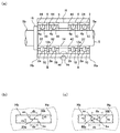
図1(a)〜(c)には、本発明の一実施形態に係る軸受ユニットが示されており、当該軸受ユニットには、相対回転可能に対向配置された一対の軌道輪22,42,62,82,24,44,64,84で成る4つ以上の軸受2,4,6,8と、一端部Sbから他端部Saまで延出し、前記軸受2,4,6,8の一方の軌道輪22,42,62,82が固定される軸Sと、当該軸受2,4,6,8の他方の軌道輪24,44,64,84が固定されるハウジングHが備えられている。
Hereinafter, a bearing unit according to an embodiment of the present invention will be described with reference to the accompanying drawings.
1 (a) to 1 (c) show a bearing unit according to an embodiment of the present invention. The bearing unit includes a pair of
この場合、軸Sは、図示しない所定の基板(例えば、ハードディスクドライブ(HDD)のベースプレートなど)に一端部Sbが固定され、当該一端部Sbから所定長さで他端部Saまで延出されているとともに、ハウジング(例えは、HDDのスリーブなど)Hは、軸Sの外径寸法よりも大きな内径寸法に設定された円筒状を成しており、当該軸Sの外周部を覆うように位置付けられている。そして、当該軸Sに対して所定の回動部材(例えば、HDDのスイングアームなど)を回動自在に支持するために、4つの転がり軸受2,4,6,8が軸SとハウジングHの間に介在されている。
In this case, the shaft S has one end Sb fixed to a predetermined substrate (not shown) (for example, a base plate of a hard disk drive (HDD)), and extends from the one end Sb to the other end Sa by a predetermined length. In addition, the housing (for example, HDD sleeve) H has a cylindrical shape set to an inner diameter larger than the outer diameter of the shaft S, and is positioned so as to cover the outer peripheral portion of the shaft S. It has been. The four
具体的には、各転がり軸受2,4,6,8は、相対回転可能に内輪22,42,62,82と外輪24,44,64,84が対向配置され、当該内外輪間に転動可能に複数の転動体(玉)10が組み込まれた構成を成しており、各内輪22,42,62,82がその内周面を軸Sの外周面と密着させて固定されているとともに、各外輪24,44,64,84がその外周面をハウジングHの内周面と密着させて固定されている。その際、内輪22,42,62,82と軸Sとの固定方法、及び外輪24,44,64,84とハウジングHとの固定方法は、これらを相互に安定して固定することが可能であれば、特に限定されない。例えば、嵌合固定や圧入固定など任意の方法を選択すればよいが、本実施形態においては、これらが各種の接着剤により接着固定されている場合を一例として想定する。
Specifically, each of the
なお、内輪22,42,62,82の外周面、並びに外輪24,44,64,84の内周面には、それぞれ転動体(玉)10を転動させるための軌道面2a,4aが全周に亘って形成されており、転動体(玉)10は当該軌道面2a,4a間に組み込まれている。その際、各軌道面2a,4aを転動する転動体(玉)10の転動トレースがバラつき、トルク変動(トルクのうねり)が大きくなることを防止するため、当該各軌道面2a,4aの曲率半径は、転動体(玉)の直径寸法の55%以上に設定することが好ましい。これにより、各軌道面2a,4aを転動する転動体(玉)10の転動トレースを安定させ、トルクのうねりを低減させることができる。
In addition, on the outer peripheral surfaces of the
また、転動体(玉)10は、保持器(図示しない)のポケット内に1つずつ回転自在に保持された状態で、軌道面2a,4a間に組み込んでもよい。これにより、各転動体(玉)10は、所定間隔を保った状態で、その転動面が相互に接触することなく、軌道面2a,4a間を転動することができ、結果として、当該各転動体(玉)10が相互に接触して摩擦が生じることによる回転抵抗の増大や、焼付きなどを防止することができる。
Further, the rolling elements (balls) 10 may be incorporated between the
ここで、転動体10としては、図1(a)に示すような玉を適用してもよいし、軸受ユニットの使用条件や使用目的などに応じて各種のころ(円錐ころ、円筒ころ及び球面ころなど)を適用してもよい。また、保持器としては、転動体10の種類に応じて任意のタイプを適用すればよい。例えば、転動体を玉とした場合、波型の合わせタイプや冠型などのタイプを適用することができ、転動体を各種のころ(円錐ころ、円筒ころ及び球面ころなど)とした場合、もみ抜き型、くし型及びかご型などのタイプを適用することができる。その際、保持器の材質は特に限定されず、転動体10の種類や材質(金属、樹脂、セラミック等)などに応じて各種の金属製や樹脂製などとすればよい。
Here, as the
また、図1(a)に示す構成においては、同図の右側に位置する2つの転がり軸受2,4が一組とされているとともに、同図の左側に位置する2つの転がり軸受6,8が一組とされている。転がり軸受2,4の外輪24,44の間には、円環状を成す間座12aが介在されており、当該間座12aは、軸Sの延出方向(図1(a)の左右方向(以下、軸方向という))の両端面が軸方向へ相対する外輪24の端面及び外輪44の端面と当接するように位置付けられている(以下、一組の軸受2,4と間座12aの組付体を軸受Aという)。一方、転がり軸受6,8の外輪64,84の間には、円環状を成す間座12bが介在されており、当該間座12bは、軸方向の両端面が当該軸方向へ相対する外輪64の端面及び外輪84の端面と当接するように位置付けられている(以下、一組の軸受6,8と間座12bの組付体を軸受Bという)。
なお、間座12a,12bは、必ずしも円環状の部材でなくともよく、例えば、環の一部が欠落されたC字状を成す部材などであってもよい。
Further, in the configuration shown in FIG. 1 (a), two rolling
The
そして、軸受Aと軸受Bの内輪42,62の間には、円筒状を成すスペーサ14が介在されており、当該スペーサ14は、軸方向の両端面が当該軸方向へ相対する内輪42の端面及び内輪62の端面と当接するように位置付けられている。ただし、スペーサ14は、必ずしも円筒状の部材でなくともよく、例えば、環の一部が欠落された断面の輪郭形状がC字状を成す部材などであってもよい。
軸受Aと軸受Bをこのように位置付けることで、間座12a,12b及びスペーサ14によって軸方向に対して所定位置に位置決めされるとともに、これらの軸受A,B(2,4,6,8)に対して所定の予圧が付与されている。なお、転がり軸受8の軸方向の一端部Sb側には、所定の係止部材(例えば、環状部材や環の一部が欠落されたC字状を成す部材など)16が軸Sに外装されており、当該係止部材16の外装位置を基準として、軸受A及び軸受Bが軸Sに対して位置決めされている。
A
By positioning the bearings A and B in this way, the
本実施形態において、ハウジングHは、2つの構造体Ha,Hbが組み付けられて一体となる分割構造を成しており、各構造体Ha,Hbに転がり軸受2,4,6,8の外輪24,44,64,84が2つ以上ずつそれぞれ固定されるとともに、前記各構造体Ha,Hbが軸方向に相対する端面as,bs同士を突き当てた状態で固定されることで、一体を成して組み付けられている。図1(a)には、ハウジングHを軸方向の略中間位置で分割した2つの円筒状の構造体(以下、第1ハウジングHa及び第2ハウジングHbという)を組み付けて一体化される分割構造が示されている。
In the present embodiment, the housing H has a divided structure in which two structures Ha and Hb are assembled and integrated, and the
この場合、第1ハウジングHaは、一例として、その内径寸法が軸受A(転がり軸受2,4の外輪24,44及び間座12a)の外径寸法と略同一寸法に設定され、その軸方向寸法が軸受Aの軸方向寸法よりも大きな寸法に設定された所定の肉厚の円筒状を成している。また、第2ハウジングHbは、一例として、その内径寸法が軸受B(転がり軸受6,8の外輪64,84及び間座12b)の外径寸法と略同一寸法に設定され、その軸方向寸法が軸受Bの軸方向寸法よりも大きな寸法に設定された所定の肉厚の円筒状を成している。なお、第1ハウジングHa及び第2ハウジングHbの肉厚は、例えば、これらのハウジングHa,Hbの材質や軸受ユニットの使用条件や使用目的などに応じて任意の値に設定すればよいため、ここでは特に限定しない。
In this case, as an example, the inner diameter of the first housing Ha is set to be approximately the same as the outer diameter of the bearing A (the
このような分割構造を成すハウジングHに対しては、第1ハウジングHaに軸受A(具体的には、転がり軸受2,4の外輪24,44及び間座12a)が接着固定されており、第2ハウジングHbに軸受B(具体的には、転がり軸受6,8の外輪64,84及び間座12b)が接着固定されている。これにより、4つの転がり軸受2,4,6,8で構成される軸受ユニットでありながら、第1ハウジングHaごとに、並びに第2ハウジングHbごとに軸受の取付作業を行うことが可能となる。したがって、2つの転がり軸受で構成される軸受ユニット、すなわち1つのハウジングに2つの軸受が固定される構造の軸受ユニットと同様にユニット自身の組立作業を行うことができ、4つの転がり軸受2,4,6,8で構成される軸受ユニットであっても、前記組立作業をスムーズに行うことができる。
For the housing H having such a divided structure, the bearing A (specifically, the outer rings 24 and 44 of the rolling
さらに、軸受Aが接着固定された第1ハウジングHaと軸受Bが接着固定された第2ハウジングHbとは、当該第1ハウジングHaの端面asと当該第2ハウジングHbの端面bsとを突き当てた状態で固定されることで、一体を成して組み付けられている。その際、端面as,bs同士の固定方法は、これらを相互に安定して固定することが可能であれば、特に限定されない。例えば、嵌合固定や圧入固定など任意の方法を選択すればよいが、本実施形態においては、これらが各種の接着剤により接着固定されている場合を一例として想定する。 Further, the first housing Ha to which the bearing A is bonded and fixed and the second housing Hb to which the bearing B is bonded and fixed abut the end surface as of the first housing Ha and the end surface bs of the second housing Hb. By being fixed in a state, it is assembled integrally. At that time, the fixing method of the end faces as and bs is not particularly limited as long as they can be stably fixed to each other. For example, any method such as fitting and press-fitting may be selected, but in the present embodiment, a case where these are bonded and fixed with various adhesives is assumed as an example.
また、端面as,bs同士を接着固定するタイミングは、第1ハウジングHaと軸受Aとの接着固定、及び第2ハウジングHbと軸受Bとの接着固定がいずれも完了した後であってもよいが、これらの接着固定と同時に行うことが好ましい。これにより、第1ハウジングHaと第2ハウジングHbの分割構造のハウジングHでありながら、単一の部材で成る一体構造のハウジングと同様の取り扱いをすることが可能となり、軸受ユニットを装置(例えば、HDD)へ容易に組み込むことができる。 Further, the timing of bonding and fixing the end surfaces as and bs may be after the bonding and fixing of the first housing Ha and the bearing A and the bonding and fixing of the second housing Hb and the bearing B are completed. It is preferable to carry out simultaneously with these adhesive fixings. Thereby, although it is the housing H of the divided structure of the first housing Ha and the second housing Hb, it can be handled in the same manner as the single-piece housing composed of a single member, and the bearing unit can be attached to the device (for example, HDD).
なお、第1ハウジングHaの端面asと第2ハウジングHbの端面bsの突き当て部位の構造(突き合わせ構造)は、これらの第1ハウジングHaと第2ハウジングHbを相互に安定して、かつスムーズに固定することが可能な構造であれば特に限定されず、軸受ユニットの使用条件や使用目的などに応じて任意の構造を選択することができる。 The structure (butting structure) of the abutting portion of the end surface as of the first housing Ha and the end surface bs of the second housing Hb is stable and smooth between the first housing Ha and the second housing Hb. The structure is not particularly limited as long as it can be fixed, and an arbitrary structure can be selected according to the use condition or purpose of the bearing unit.
例えば、図1(b)には、第1ハウジングHa及び第2ハウジングHbに対し、相互に係合可能な段差部30a,30bを端面as,bsにそれぞれ形成し、当該段差部30a,30bを係合させることで、これらの第1ハウジングHa及び第2ハウジングHbが一体を成して組み付けられる段差構造を一例として示している。
また、図1(c)には、第1ハウジングHa及び第2ハウジングHbに対し、端面as,bsを相互に同一角度で逆方向にそれぞれ傾斜させた傾斜部50a,50bを形成し、当該傾斜部50a,50bを密着させることで、これらの第1ハウジングHa及び第2ハウジングHbが一体を成して組み付けられる傾斜構造を一例として示している。
For example, in FIG. 1B, stepped
In FIG. 1 (c),
図1(b)に示す構成において、第1ハウジングHaは、端面asの外径側(同図の下側)が全周に亘って所定の深さ(同図の距離da)で、所定の径(同、距離ra)だけ縮径されるように、当該外径側の肉が矩形の凹状に欠落された段差形状を成している(以下、かかる段差部分を第1段差部30aという)。これに対し、第2ハウジングHbは、端面bsの内径側(同図の上側)が全周に亘って所定の深さ(同図の距離db)で、所定の径(同、距離rb)だけ拡径されるように、当該内径側の肉が矩形の凹状に欠落された段差形状を成している(以下、かかる段差部分を第2段差部30bという)。
In the configuration shown in FIG. 1 (b), the first housing Ha has a predetermined depth (distance da in the figure) on the outer diameter side (the lower side in the figure) of the end surface as at a predetermined depth. The outer diameter side meat has a stepped shape with a rectangular concave shape so that the diameter is reduced by the diameter (distance ra) (hereinafter, this stepped portion is referred to as a first stepped
一例として、この場合、第1段差部30aと第2段差部30bは、その深さda,dbが同一寸法に設定されているとともに、その径ra,rbが同一寸法(第1ハウジングHa及び第2ハウジングHbの肉厚寸法の略半寸)に設定されている。なお、第1段差部30aと第2段差部30bの深さda,dbは、それぞれ同一のあるいは異なる任意の寸法に設定することができるが、段差部30a,30bを係合させ、第1ハウジングHa及び第2ハウジングHbをより安定して一体的に組み付けるためには、同一寸法に設定することが好ましい。
As an example, in this case, the first stepped
深さda,db及び径ra,rbをこのような設定とすることで、第1段差部30aと第2段差部30bを軸方向に突き当てることにより、これらの段差部30a,30bを相互に容易、かつ隙間なく係合させることができる。この結果、第1ハウジングHaと第2ハウジングHbは、一方の端面as,bsが他方の段差部30a,30bに突き当てられた状態となり、これらのハウジングHa,Hbを強固に一体を成して組み付けることができる。また、その際には、第1段差部30a及び第2段差部30bがガイドとなるため、第1ハウジングHaと第2ハウジングHbの組み付けを非常にスムーズに行うことができる。
By setting the depth da, db and the diameter ra, rb in such a manner, the first stepped
また、段差部30a,30bの径ra,rbが同一寸法(第1ハウジングHa及び第2ハウジングHbの肉厚寸法の略半寸)に設定されているため、第1ハウジングHaと第2ハウジングHbを容易に同芯上に位置付けることができるとともに、これらのハウジングHa,Hbに固定された軸受A(具体的には、転がり軸受2,4及び間座12a)と、軸受B(具体的には、転がり軸受6,8及び間座12b)を容易に同芯上に位置決め固定(接着固定)することができる。
Further, since the diameters ra and rb of the stepped
すなわち、第1ハウジングHa、第2ハウジングHb、軸受A(転がり軸受2,4及び間座12a)、及び軸受B(転がり軸受6,8及び間座12b)の同芯度を高めることができる。この結果、軸受ユニットの剛性(特にラジアル剛性)が高められ、軸受ユニットのトルクのうねりを改善することができる。また、かかる軸受ユニットを装置(例えば、HDD)に組み込む前に、当該軸受ユニットのトルクのうねりなどを評価することができるため、前記装置の初期不良の発生を低減させることが可能となる。
That is, the concentricity of the first housing Ha, the second housing Hb, the bearing A (the rolling
また、図1(c)に示す構成において、第1ハウジングHaは、端面asの外径側(同図の下側)が全周に亘って所定の深さ(同図の距離da)で、当該端面asへ向かうに従って徐々に所定の径(同、距離ra)だけ縮径されるように、当該外径側の肉が欠落された傾斜形状を成している(以下、かかる傾斜部分を第1傾斜部50aという)。これに対し、第2ハウジングHbは、端面bsの内径側(同図の上側)が全周に亘って所定の深さ(同図の距離db)で、当該端面bsへ向かうに従って徐々に所定の径(同、距離rb)だけ拡径されるように、当該内径側の肉が欠落された傾斜形状を成している(以下、かかる傾斜部分を第2傾斜部50bという)。
In the configuration shown in FIG. 1C, the first housing Ha has an outer diameter side (the lower side in the figure) of the end surface as having a predetermined depth (distance da in the figure) over the entire circumference. In order to gradually reduce the diameter by a predetermined diameter (same as the distance ra) toward the end surface as, an inclined shape is formed in which the meat on the outer diameter side is missing (hereinafter, the inclined portion is referred to as the first portion). 1
一例として、この場合、第1傾斜部50aと第2傾斜部50bは、その深さda,dbが同一寸法に設定されているとともに、その径ra,rbが同一寸法(第1ハウジングHa及び第2ハウジングHbの肉厚寸法よりも小寸)に設定されている。これにより、第1傾斜部50aと第2傾斜部50bを、相互に同一角度(図1(c)の角度θ)で逆方向にそれぞれ傾斜させた構造とすることができる。なお、第1傾斜部50aと第2傾斜部50bの深さda,dbは、それぞれ同一のあるいは異なる任意の寸法に設定することができるが、傾斜部50a,50bを密着させ、第1ハウジングHa及び第2ハウジングHbをより安定して一体的に組み付けるためには、同一寸法に設定することが好ましい。
As an example, in this case, the first
深さda,db及び径ra,rbをこのような設定とすることで、第1傾斜部50aと第2傾斜部50bを軸方向に突き当てることにより、これらの傾斜部50a,50bを相互に容易、かつ隙間なく密着させることができ、第1ハウジングHaと第2ハウジングHbを強固に一体を成して組み付けることができる。また、その際には、第1傾斜部50a及び第2傾斜部50bがガイドとなるため、第1ハウジングHaと第2ハウジングHbの組み付けを非常にスムーズに行うことができる。
By setting the depth da, db and the diameter ra, rb in such a manner, the first
また、傾斜部50a,50bの傾斜角度が同一角度θに設定されている(傾斜部50a,50bが同一角度θで傾斜している)ため、これらの傾斜部50a,50bを相互に軸方向に突き当てた際、その傾斜面に沿って第1ハウジングHa及び第2ハウジングHbの相対的な位置をフレキシブルに調整することができる。したがって、上述したような端面as,bsに段差部30a,30bを形成した場合(図1(b))と比べ、第1ハウジングHaと第2ハウジングHbを容易に、かつより高精度に同芯上に位置付けることができるとともに、これらのハウジングHa,Hbに固定された軸受A(具体的には、転がり軸受2,4及び間座12a)と、軸受B(具体的には、転がり軸受6,8及び間座12b)を容易に、かつより高精度に同芯上に位置決め固定(接着固定)することができる。
In addition, since the inclination angles of the
すなわち、第1ハウジングHa、第2ハウジングHb、軸受A(転がり軸受2,4及び間座12a)、及び軸受B(転がり軸受6,8及び間座12b)の同芯度をさらに高めることができる。この結果、軸受ユニットの剛性(特にラジアル剛性)をより高められ、軸受ユニットのトルクのうねりをさらに改善することができる。また、かかる軸受ユニットを装置(例えば、HDD)に組み込む前に、当該軸受ユニットのトルクのうねりなどをより高精度に評価することができるため、前記装置の初期不良の発生をさらに低減させることが可能となる。
That is, the concentricity of the first housing Ha, the second housing Hb, the bearing A (the rolling
なお、上述した本実施形態においては、第1ハウジングHa及び第2ハウジングHbの材質について特に言及しなかったが、軸受ユニットの使用条件や使用目的などに応じて任意の素材を選択してこれらのハウジングHa,Hbを成形すればよい。 In the above-described embodiment, the material of the first housing Ha and the second housing Hb is not particularly mentioned, but any material is selected according to the use condition or purpose of use of the bearing unit. The housings Ha and Hb may be molded.
例えば、これらのハウジングHa,Hbを各種の金属製とした場合、バー材より旋削加工して内径面及び外径面を仕上げるとともに、段差部30a,30b、あるいは傾斜部50a,50bを同時に旋削加工する。その後、研削加工してより高精度に仕上げることもできる。
For example, when these housings Ha and Hb are made of various metals, the inner and outer diameter surfaces are finished by turning from the bar material, and the stepped
また、第1ハウジングHa及び第2ハウジングHbのいずれか一方、あるいは双方に対し、間座12a,12bを一体的に形成した構造としてもよい。これにより、部品点数を減少させることができ、組立作業をより効率化することができる。
Further, the
2,4,6,8 転がり軸受
22,42,62,82 内輪
24,44,64,84 外輪
H ハウジング
Ha 第1ハウジング
Hb 第2ハウジング
S 軸
Sa 軸他端部
Sb 軸一端部
as,bs ハウジング端面
2, 4, 6, 8
Claims (5)
前記4つの軸受は2つずつの第1と第2の2組の軸受から構成され、各組の2つの軸受の外輪間に間座が介在されるとともに、当該第1の組の軸受の内輪と当該第2の組の軸受の内輪との間にスペーサが介在され、
前記ハウジングは、所定の肉厚の円筒状とされた、第1と第2の2つのハウジングが組み付けられて一体となる分割構造を成しており、当該第1のハウジングに前記第1の組の軸受の両外輪が、当該第2のハウジングに前記第2の組の軸受の両外輪がそれぞれ固定されるとともに、当該第1と第2のハウジングの軸方向寸法は、それぞれ、前記第1と第2の組の軸受の軸方向寸法よりも大きな寸法とされ、
前記第1と第2のハウジングは、外径側の肉が欠落された一方のハウジングと、内径側の肉が欠落された他方のハウジングとが、前記第1と第2の組の互いに隣接する外輪の間にて、相対する端面同士を相互に隙間なく突き当てた状態で係合させて固定されることで、一体を成して組み付けられることを特徴とする磁気ディスク装置のスイングアーム用軸受ユニット。 Four bearing including a pair of inner and outer rings which are rotatable relative to opposed, extending from one end to the other end, a shaft the inner race of the bearing is fixed, the outer ring of the bearing is fixed A bearing unit for a swing arm of a magnetic disk device, comprising a housing for mounting a swing arm that is rotatable along the axis ,
The four bearings are composed of two pairs of first and second sets of bearings, with a spacer interposed between the outer rings of the two bearings of each set, and the inner rings of the first set of bearings. And a spacer is interposed between the inner ring of the second set of bearings,
The housing has a cylindrical structure with a predetermined thickness, and has a split structure in which the first and second housings are assembled together, and the first set is attached to the first housing. Both outer rings of the bearings are fixed to the second housing, and both outer rings of the second set of bearings are fixed to the second housing, and the axial dimensions of the first and second housings are the first and second bearings, respectively. A dimension greater than the axial dimension of the second set of bearings;
In the first and second housings, one housing from which the outer diameter side meat is missing and the other housing from which the inner diameter side meat is missing are adjacent to each other in the first and second sets. A bearing for a swing arm of a magnetic disk device, wherein the bearings are assembled in an integrated manner by engaging and fixing the end faces facing each other with no gap between the outer rings. unit.
前記第1と第2のハウジングには、前記軸受を接着により固定し、
当該第1と第2のハウジングは、前記端面同士を接着により固定することで、一体を成して組み付け、当該端面同士の接着は、前記第1と第2のハウジングと前記軸受との接着固定と同時に行うことを特徴とする磁気ディスク装置のスイングアーム用軸受ユニット製造方法。 A method for manufacturing a bearing unit for a swing arm of a magnetic disk device according to claim 1 ,
The bearings are fixed to the first and second housings by bonding,
The first and second housings are assembled together by fixing the end faces by bonding, and the end faces are bonded to each other by bonding the first and second housings to the bearing. A method for manufacturing a bearing unit for a swing arm of a magnetic disk device, wherein the method is performed simultaneously.
当該第1と第2のハウジングは、前記端面同士を接着により固定することで、一体を成して組み付け、当該端面同士の接着は、前記第1と第2のハウジングと前記軸受の外輪との接着固定と同時に行うことを特徴とする請求項4に記載の磁気ディスク装置のスイングアーム用軸受ユニット製造方法。
Two outer rings of the bearing are fixed to each of the first and second housings by bonding,
The first and second housings are assembled together by fixing the end surfaces by bonding, and the bonding between the end surfaces is performed between the first and second housings and the outer ring of the bearing. 5. The method for manufacturing a swing arm bearing unit for a magnetic disk drive according to claim 4 , wherein the method is performed simultaneously with adhesive fixing.
Priority Applications (1)
| Application Number | Priority Date | Filing Date | Title |
|---|---|---|---|
| JP2008034843A JP5018538B2 (en) | 2008-02-15 | 2008-02-15 | Bearing unit for swing arm of magnetic disk device, and method for manufacturing swing arm bearing unit of magnetic disk device |
Applications Claiming Priority (1)
| Application Number | Priority Date | Filing Date | Title |
|---|---|---|---|
| JP2008034843A JP5018538B2 (en) | 2008-02-15 | 2008-02-15 | Bearing unit for swing arm of magnetic disk device, and method for manufacturing swing arm bearing unit of magnetic disk device |
Publications (3)
| Publication Number | Publication Date |
|---|---|
| JP2009192014A JP2009192014A (en) | 2009-08-27 |
| JP2009192014A5 JP2009192014A5 (en) | 2010-11-25 |
| JP5018538B2 true JP5018538B2 (en) | 2012-09-05 |
Family
ID=41074213
Family Applications (1)
| Application Number | Title | Priority Date | Filing Date |
|---|---|---|---|
| JP2008034843A Active JP5018538B2 (en) | 2008-02-15 | 2008-02-15 | Bearing unit for swing arm of magnetic disk device, and method for manufacturing swing arm bearing unit of magnetic disk device |
Country Status (1)
| Country | Link |
|---|---|
| JP (1) | JP5018538B2 (en) |
Families Citing this family (2)
| Publication number | Priority date | Publication date | Assignee | Title |
|---|---|---|---|---|
| JP5615465B2 (en) * | 2012-06-29 | 2014-10-29 | 三菱重工業株式会社 | Shaft system assembling method and shaft system assembling jig for a regenerative energy generator |
| JP5615466B2 (en) * | 2012-06-29 | 2014-10-29 | 三菱重工業株式会社 | Shaft system assembling method and shaft system assembling jig for regenerative energy generator |
Family Cites Families (6)
| Publication number | Priority date | Publication date | Assignee | Title |
|---|---|---|---|---|
| EP0126607A3 (en) * | 1983-05-19 | 1985-11-21 | Federal-Mogul Corporation | Cartridge bearing apparatus and method |
| JP2000310224A (en) * | 1999-04-28 | 2000-11-07 | Nsk Ltd | Spindle device |
| JP2002227862A (en) * | 2001-01-29 | 2002-08-14 | Nsk Ltd | Rolling bearing device |
| JP4383766B2 (en) * | 2003-04-18 | 2009-12-16 | Ntn株式会社 | Synthetic resin cages and angular contact ball bearings for angular contact ball bearings |
| JP2005207455A (en) * | 2004-01-20 | 2005-08-04 | Nsk Ltd | Pivot bearing device of bearing device hdd and assembling method for bearing device |
| JP2005188756A (en) * | 2005-03-04 | 2005-07-14 | Nsk Ltd | Rolling bearing unit for swing arms |
-
2008
- 2008-02-15 JP JP2008034843A patent/JP5018538B2/en active Active
Also Published As
| Publication number | Publication date |
|---|---|
| JP2009192014A (en) | 2009-08-27 |
Similar Documents
| Publication | Publication Date | Title |
|---|---|---|
| US6655847B2 (en) | Pivot bearing assembly | |
| JP6158482B2 (en) | Pivot bearing unit for hard disk actuator | |
| JP2007305268A (en) | Bearing unit | |
| JP5018538B2 (en) | Bearing unit for swing arm of magnetic disk device, and method for manufacturing swing arm bearing unit of magnetic disk device | |
| JP6304795B2 (en) | Manufacturing method of bearing device | |
| JP2009243555A (en) | Bearing unit and pivot device | |
| JP3419053B2 (en) | Double-row rolling bearing device with preload | |
| US6554479B2 (en) | Bell bearing and method of producing the same | |
| US7056030B2 (en) | Pivot bearing for a swing arm of a hard disk drive device | |
| US8786981B2 (en) | Bearing device, method of manufacturing bearing device, and information recording/reproducing apparatus | |
| JP6529211B2 (en) | Bearing device, manufacturing method of bearing device, and information recording and reproducing apparatus | |
| JP6209374B2 (en) | Bearing device, bearing device manufacturing method, and information recording / reproducing device | |
| JP2010190403A (en) | Rolling bearing device and pivot device | |
| JP6210623B2 (en) | Bearing device, bearing device manufacturing method, and information recording / reproducing device | |
| JP5144558B2 (en) | Rolling bearing device | |
| JP6508972B2 (en) | Bearing device and magnetic recording device | |
| JP6230421B2 (en) | Bearing device and information recording / reproducing device | |
| JP6493936B2 (en) | Manufacturing method of bearing device | |
| JP2013024396A (en) | Bearing retainer | |
| JP2008144783A (en) | Bearing fixing method | |
| JP2006214504A (en) | Rolling bearing device | |
| JP2004286070A (en) | Bearing device, and pivot assembly provided with the same | |
| JP2004270797A (en) | Bearing apparatus, head supporting apparatus and recording reproducing and apparatus | |
| JP2007292149A (en) | Bearing unit | |
| JP2006002875A (en) | Rolling bearing for swing arm and rolling bearing device |
Legal Events
| Date | Code | Title | Description |
|---|---|---|---|
| A621 | Written request for application examination |
Free format text: JAPANESE INTERMEDIATE CODE: A621 Effective date: 20100830 |
|
| A521 | Written amendment |
Free format text: JAPANESE INTERMEDIATE CODE: A523 Effective date: 20101013 |
|
| A977 | Report on retrieval |
Free format text: JAPANESE INTERMEDIATE CODE: A971007 Effective date: 20111027 |
|
| A131 | Notification of reasons for refusal |
Free format text: JAPANESE INTERMEDIATE CODE: A131 Effective date: 20111108 |
|
| A521 | Written amendment |
Free format text: JAPANESE INTERMEDIATE CODE: A523 Effective date: 20120105 |
|
| TRDD | Decision of grant or rejection written | ||
| A01 | Written decision to grant a patent or to grant a registration (utility model) |
Free format text: JAPANESE INTERMEDIATE CODE: A01 Effective date: 20120515 |
|
| A01 | Written decision to grant a patent or to grant a registration (utility model) |
Free format text: JAPANESE INTERMEDIATE CODE: A01 |
|
| A61 | First payment of annual fees (during grant procedure) |
Free format text: JAPANESE INTERMEDIATE CODE: A61 Effective date: 20120528 |
|
| R150 | Certificate of patent or registration of utility model |
Ref document number: 5018538 Country of ref document: JP Free format text: JAPANESE INTERMEDIATE CODE: R150 Free format text: JAPANESE INTERMEDIATE CODE: R150 |
|
| FPAY | Renewal fee payment (event date is renewal date of database) |
Free format text: PAYMENT UNTIL: 20150622 Year of fee payment: 3 |