JP5017600B2 - Evaluation method of non-uniform directional residual stress using instrumented indentation test method - Google Patents
Evaluation method of non-uniform directional residual stress using instrumented indentation test method Download PDFInfo
- Publication number
- JP5017600B2 JP5017600B2 JP2009548978A JP2009548978A JP5017600B2 JP 5017600 B2 JP5017600 B2 JP 5017600B2 JP 2009548978 A JP2009548978 A JP 2009548978A JP 2009548978 A JP2009548978 A JP 2009548978A JP 5017600 B2 JP5017600 B2 JP 5017600B2
- Authority
- JP
- Japan
- Prior art keywords
- residual stress
- indentation
- ratio
- stress
- load
- Prior art date
- Legal status (The legal status is an assumption and is not a legal conclusion. Google has not performed a legal analysis and makes no representation as to the accuracy of the status listed.)
- Active
Links
- 238000007373 indentation Methods 0.000 title claims description 236
- 238000011156 evaluation Methods 0.000 title claims description 22
- 238000010998 test method Methods 0.000 title claims description 22
- 238000006073 displacement reaction Methods 0.000 claims description 86
- 238000006243 chemical reaction Methods 0.000 claims description 59
- 238000012360 testing method Methods 0.000 claims description 53
- 238000000034 method Methods 0.000 claims description 40
- 238000004590 computer program Methods 0.000 claims description 4
- 239000000463 material Substances 0.000 description 41
- 230000000694 effects Effects 0.000 description 17
- 238000002474 experimental method Methods 0.000 description 16
- 229910000831 Steel Inorganic materials 0.000 description 10
- 239000010959 steel Substances 0.000 description 10
- 238000005452 bending Methods 0.000 description 9
- 230000001066 destructive effect Effects 0.000 description 9
- 238000011160 research Methods 0.000 description 9
- 238000011161 development Methods 0.000 description 8
- 238000004458 analytical method Methods 0.000 description 6
- 239000013078 crystal Substances 0.000 description 6
- 238000012795 verification Methods 0.000 description 6
- 238000010438 heat treatment Methods 0.000 description 5
- 238000002360 preparation method Methods 0.000 description 5
- 238000010586 diagram Methods 0.000 description 4
- 102200082816 rs34868397 Human genes 0.000 description 4
- 239000010409 thin film Substances 0.000 description 4
- 238000003466 welding Methods 0.000 description 4
- 238000005094 computer simulation Methods 0.000 description 3
- 230000000704 physical effect Effects 0.000 description 3
- 238000000137 annealing Methods 0.000 description 2
- 238000005266 casting Methods 0.000 description 2
- 230000005489 elastic deformation Effects 0.000 description 2
- 238000003754 machining Methods 0.000 description 2
- 238000004519 manufacturing process Methods 0.000 description 2
- 238000005259 measurement Methods 0.000 description 2
- 238000000691 measurement method Methods 0.000 description 2
- 238000003825 pressing Methods 0.000 description 2
- 238000012545 processing Methods 0.000 description 2
- 239000012925 reference material Substances 0.000 description 2
- 230000003746 surface roughness Effects 0.000 description 2
- 238000009864 tensile test Methods 0.000 description 2
- 230000009466 transformation Effects 0.000 description 2
- 230000007704 transition Effects 0.000 description 2
- 229910001204 A36 steel Inorganic materials 0.000 description 1
- OKTJSMMVPCPJKN-UHFFFAOYSA-N Carbon Chemical compound [C] OKTJSMMVPCPJKN-UHFFFAOYSA-N 0.000 description 1
- 238000005848 Knoop reaction Methods 0.000 description 1
- 238000007545 Vickers hardness test Methods 0.000 description 1
- 238000013459 approach Methods 0.000 description 1
- 238000004364 calculation method Methods 0.000 description 1
- 229910052799 carbon Inorganic materials 0.000 description 1
- 239000011248 coating agent Substances 0.000 description 1
- 238000000576 coating method Methods 0.000 description 1
- 239000002131 composite material Substances 0.000 description 1
- 238000001816 cooling Methods 0.000 description 1
- 238000005260 corrosion Methods 0.000 description 1
- 230000007797 corrosion Effects 0.000 description 1
- 238000005520 cutting process Methods 0.000 description 1
- 230000007423 decrease Effects 0.000 description 1
- 229910003460 diamond Inorganic materials 0.000 description 1
- 239000010432 diamond Substances 0.000 description 1
- 239000012530 fluid Substances 0.000 description 1
- 238000005242 forging Methods 0.000 description 1
- 230000010354 integration Effects 0.000 description 1
- 238000005304 joining Methods 0.000 description 1
- 239000002184 metal Substances 0.000 description 1
- 239000000203 mixture Substances 0.000 description 1
- 230000003287 optical effect Effects 0.000 description 1
- 239000002245 particle Substances 0.000 description 1
- 230000035515 penetration Effects 0.000 description 1
- 238000005498 polishing Methods 0.000 description 1
- 230000002250 progressing effect Effects 0.000 description 1
- 238000001953 recrystallisation Methods 0.000 description 1
- 230000000452 restraining effect Effects 0.000 description 1
- 238000005096 rolling process Methods 0.000 description 1
- 235000019592 roughness Nutrition 0.000 description 1
- 238000005480 shot peening Methods 0.000 description 1
Images


Classifications
-
- G—PHYSICS
- G01—MEASURING; TESTING
- G01N—INVESTIGATING OR ANALYSING MATERIALS BY DETERMINING THEIR CHEMICAL OR PHYSICAL PROPERTIES
- G01N3/00—Investigating strength properties of solid materials by application of mechanical stress
- G01N3/40—Investigating hardness or rebound hardness
- G01N3/42—Investigating hardness or rebound hardness by performing impressions under a steady load by indentors, e.g. sphere, pyramid
-
- G—PHYSICS
- G01—MEASURING; TESTING
- G01N—INVESTIGATING OR ANALYSING MATERIALS BY DETERMINING THEIR CHEMICAL OR PHYSICAL PROPERTIES
- G01N3/00—Investigating strength properties of solid materials by application of mechanical stress
- G01N3/08—Investigating strength properties of solid materials by application of mechanical stress by applying steady tensile or compressive forces
-
- G—PHYSICS
- G01—MEASURING; TESTING
- G01N—INVESTIGATING OR ANALYSING MATERIALS BY DETERMINING THEIR CHEMICAL OR PHYSICAL PROPERTIES
- G01N2203/00—Investigating strength properties of solid materials by application of mechanical stress
- G01N2203/02—Details not specific for a particular testing method
- G01N2203/025—Geometry of the test
- G01N2203/0254—Biaxial, the forces being applied along two normal axes of the specimen
-
- G—PHYSICS
- G01—MEASURING; TESTING
- G01N—INVESTIGATING OR ANALYSING MATERIALS BY DETERMINING THEIR CHEMICAL OR PHYSICAL PROPERTIES
- G01N2203/00—Investigating strength properties of solid materials by application of mechanical stress
- G01N2203/02—Details not specific for a particular testing method
- G01N2203/026—Specifications of the specimen
- G01N2203/0262—Shape of the specimen
- G01N2203/0272—Cruciform specimens
Landscapes
- Physics & Mathematics (AREA)
- Health & Medical Sciences (AREA)
- Life Sciences & Earth Sciences (AREA)
- Chemical & Material Sciences (AREA)
- Analytical Chemistry (AREA)
- Biochemistry (AREA)
- General Health & Medical Sciences (AREA)
- General Physics & Mathematics (AREA)
- Immunology (AREA)
- Pathology (AREA)
- Investigating Strength Of Materials By Application Of Mechanical Stress (AREA)
Description
本発明は、材料の機械的物性評価を非破壊的に測定する計装化試験法に関するものである。また、本発明は、一般的に熔接部及び構造材料に作用する非等方的な残留応力評価法に関するものである。 The present invention relates to an instrumentation test method for nondestructively measuring the mechanical property evaluation of a material. The present invention also relates to an anisotropic residual stress evaluation method that generally acts on welds and structural materials.
既存の残留応力評価法は、評価材料が破壊されるか否かによって破壊的あるいは非破壊的な評価法に区分される。特に、実際に使われている建築物や産業設備の残留応力を測定するためには破壊的な実験方法が使用できないので、非破壊的な測定方法が導入される必要がある。 Existing residual stress evaluation methods are classified into destructive or non-destructive evaluation methods depending on whether or not the evaluation material is destroyed. In particular, a destructive experimental method cannot be used to measure the residual stress of a building or industrial facility that is actually used, so a non-destructive measurement method needs to be introduced.
これによって、材料の表面に連続して荷重の印加と除去を繰り返すことによって、押込荷重と押込深さ(変位)を測定し、これに基づいて残留応力を非破壊的に計算する方法に関する技術が開示されている。 Thus, there is a technique relating to a method for measuring the indentation load and the indentation depth (displacement) by repeatedly applying and removing the load on the surface of the material, and calculating the residual stress based on this measurement. It is disclosed.
例えば、大韓民国における特許登録第0416723号の“残留応力測定装置及びこの装置を用いた残留応力データ測定方法、残留応力測定方法及びこの測定方法を記録した記録媒体”、及び大韓民国における特許登録第0517857号の“連続押込試験法を用いた残留応力の測定方法”が開示されている。 For example, Patent Registration No. 0416723 in Korea “Residual Stress Measuring Device, Residual Stress Data Measuring Method Using This Device, Residual Stress Measuring Method and Recording Medium Recording This Measuring Method”, and Korean Patent Registration No. 0517857 "Residual stress measurement method using continuous indentation test method" is disclosed.
本発明は、前述した問題点を解決するために案出したものであって、材料の機械的物性評価のうち、非等方的な残留応力を非等方性圧子を用いて非破壊的に測定することを目的とする。 The present invention has been devised in order to solve the above-described problems. In the mechanical property evaluation of a material, anisotropic residual stress is nondestructively generated using an anisotropic indenter. The purpose is to measure.
前述した問題点を解決するための本発明は、一軸引張及び等方向を含んだ二軸引張残留応力を印加した後、ヌープ圧子及びビッカース圧子を用いた計装化押込試験を遂行するステップと、上記ヌープ圧子の長軸が最も大きい残留応力が印加された方向と垂直に押込まれる時の押込荷重−変位曲線の勾配と無応力状態の押込荷重−変位曲線の勾配とを比較し、ヌープ圧子の長軸が最も大きい残留応力が印加された方向と平行になるように押込まれる時の押込荷重−変位曲線の勾配と無応力状態の押込荷重−変位曲線の勾配とを比較するステップと、を含む計装化押込試験法を用いた非等方向残留応力の評価方法を提供する。 The present invention for solving the above-described problems includes a step of performing an instrumented indentation test using a Knoop indenter and a Vickers indenter after applying a biaxial tensile residual stress including uniaxial tension and equal direction, and indentation load of gradients and stress-free state of the displacement curve - - indentation load when the long axis of the Knoop indenter pushed perpendicular to the largest and the direction of the residual stress is applied by comparing the slope of the displacement curve, Knoop indenter comparing a slope of the displacement curve, - indentation load of gradients and stress-free state of the displacement curve - the long axis of the pushing load when the largest residual stress pushed so as to be parallel to the direction applied A method for evaluating non-uniform residual stress using an instrumented indentation test method is provided.
この際、上記ヌープ圧子は、長軸と短軸との割合が7.11:1であってもよい。 In this case, the Knoop indenter may have a ratio of the major axis to the minor axis of 7.11: 1.
一方、一軸残留応力とヌープ圧子の長軸方向に従って残留応力と残留応力により誘導された押込荷重の差とを連結させる変換係数(α⊥,α//)の割合を決定するステップと、上記変換係数の割合と二軸残留応力状態でヌープ圧子の長軸が最も大きい残留応力が印加された方向と垂直及び水平に押込まれる時に得られる押込荷重差(ΔL1とΔL2)の割合とを用いて残留応力の異方性係数(残留応力の割合=残留応力の異方性係数:p)を決定するステップと、を更に含むことができる。 On the other hand, determining the ratio of the conversion factor (α⊥, α //) that connects the residual stress and the difference in indentation load induced by the residual stress according to the major axis direction of the Knoop indenter, and the above conversion indentation load difference obtained when the proportion and the long axis of the Knoop indenter biaxially residual stress state is the largest residual stress pushed in the vertical and horizontal directions are applied coefficients and the ratio of ([Delta] L 1 and [Delta] L 2) And determining the anisotropy coefficient of the residual stress (the ratio of the residual stress = the anisotropy coefficient of the residual stress: p).
また、上記変換係数の割合が0.34であってもよい。 Further, the ratio of the conversion coefficient may be 0.34.
また、上記残留応力の異方性係数は、上記変換係数の割合と、上記押込荷重差の割合とにより次の数式により決定できる。 Further, the anisotropy coefficient of the residual stress can be determined by the following formula based on the ratio of the conversion coefficient and the ratio of the indentation load difference.

また、上記変換係数と上記残留応力の割合及び和が含まれた次の数式を解いて、上記長軸と短軸の残留応力を決定するステップを更に含むことができる。 Further, the method may further include a step of solving the following mathematical formula including the conversion coefficient and the ratio and sum of the residual stress to determine the residual stress of the major axis and the minor axis.
また、有限要素解釈を通じて上記圧子の幾何学的形状と上記変換係数の割合とが関連することを確認するステップを更に含むことができる。 The method may further include confirming that the geometric shape of the indenter and the ratio of the conversion coefficient are related through finite element interpretation.
更に他の様態によれば、本発明は前述した計装化押込試験法が含まれたコンピュータプログラムが記録された記録媒体を提供する。 According to yet another aspect, the present invention provides a recording medium on which a computer program including the instrumented indentation test method described above is recorded.
更に他の様態によれば、本発明は前述した計装化押込試験法が含まれたコンピュータプログラムが記録された記録媒体が実行されて計装化押込試験を遂行する押込試験装置を提供する。 According to still another aspect, the present invention provides an indentation test apparatus for executing an instrumentation indentation test by executing a recording medium on which a computer program including the above-described instrumentation indentation test method is recorded.
本発明によれば、材料の機械的物性評価のうち、非等方的な残留応力が非破壊的に測定される効果がある。 According to the present invention, there is an effect that non-destructive measurement of anisotropic residual stress is performed in the mechanical property evaluation of a material.
以下、添付の図面を参照しつつ本発明の実施形態を詳細に説明する。 Hereinafter, embodiments of the present invention will be described in detail with reference to the accompanying drawings.
1.概要
残留応力(Residual stress)は、外部で作用する荷重や温度変化、拘束条件が除去された後にも材料の内部に残っている応力を定義する。大部分の材料は加工あるいは製造過程を経ながら残留応力が発生する。熱処理(heat treatment)、熔接(welding)、鋳造(casting)、切削(cutting)、引抜(drawing)、圧延(rolling)、押出(extruding)、ピーニング(shot peening)、コーティング(coating)等、全ての製造及び加工過程で発生し、熔接の場合は、降伏応力位の残留応力が存在する。また、複合材料及び薄膜の場合は界面で相互拘束により残留応力が蓄積される。
1. Overview Residual stress defines the stress that remains in the material after the externally applied load, temperature changes, and constraints are removed. Most materials generate residual stresses during processing or manufacturing processes. Heat treatment, welding, casting, cutting, drawing, rolling, extruding, shot peening, coating, etc. In the case of welding, it occurs in the manufacturing and processing process, and there is a residual stress at the yield stress level. In the case of composite materials and thin films, residual stress accumulates due to mutual restraint at the interface.
残留応力は、材料の強度及び機械的性質に影響を及ぼす。残留応力によって、疲労、破壊、腐食などが進展または遅延される効果も発生する。したがって、残留応力の正確な分析は構造設備から電子製品のように超微細な領域に至るまで重要な問題となる。 Residual stress affects the strength and mechanical properties of the material. Residual stress also causes the effect of progressing or delaying fatigue, fracture, corrosion, and the like. Therefore, accurate analysis of residual stress is an important issue from structural equipment to ultra-fine areas such as electronic products.
既存の残留応力評価法は、破壊的な方法と非破壊的な方法とに大別できる。しかしながら、既存の評価法は破壊的であるとか、試片の制限などにより、現場で使用中の材料への適用が可能でないという限界がある。これによって、試片の用意が非常に簡単で、かつ非破壊的であるため、現場適用性が優れ、局部的な物性評価が可能な計装化押込試験法(Instrumented Indentation Technique)が新たな残留応力評価方法として注目を受けている。 Existing residual stress evaluation methods can be broadly divided into destructive methods and non-destructive methods. However, there is a limit that the existing evaluation methods are destructive or cannot be applied to materials currently used in the field due to limitations of specimens. As a result, the preparation of specimens is very simple and non-destructive, so there is a new residual instrumented indentation technique that has excellent field applicability and allows local physical property evaluation. It is receiving attention as a stress evaluation method.
計装化押込試験法は、ナノからマクロスケールまで全領域に亘って適用可能である。既存の圧痕観察を通じた硬度法とは異なり、連続的に押込荷重と変位を測定することにより得られる押込荷重−変位曲線を用いて硬度及び弾性係数を含んで流動物性、残留応力、破壊靭性のような材料の機械的物性評価が可能である。 The instrumented indentation test method can be applied over the entire range from nano to macro scale. Unlike the existing hardness method through indentation observation, the indentation load-displacement curve obtained by continuously measuring the indentation load and displacement is used to determine the fluid properties, residual stress, and fracture toughness, including hardness and elastic modulus. It is possible to evaluate the mechanical properties of such materials.
多様な機械的物性評価の中でも計装化押込試験法を用いた残留応力評価法は、残留応力が存在しない無応力状態(stress-free state)と、残留応力が存在する状態の差によって発生する押込荷重の変化量と、その時の接触面積を通じて残留応力を評価する。 Among various mechanical properties, the residual stress evaluation method using the instrumented indentation test method is caused by the difference between the stress-free state where there is no residual stress and the state where there is residual stress. Residual stress is evaluated through the amount of change in indentation load and the contact area at that time.
しかしながら、等方性圧子を使用する既存の方法は、平均的な残留応力のみを測定することで、等方向二軸残留応力のみに適用される限界がある。薄膜を除いては実際の材料に存在する残留応力は非等方向二軸の場合が大部分であると知られている。 However, existing methods using isotropic indenters have limitations that apply only to isotropic biaxial residual stress by measuring only the average residual stress. Except for the thin film, it is known that the residual stress existing in the actual material is mostly non-uniform biaxial.
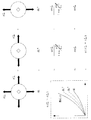
本発明者は、本明細書で非等方性圧子(ヌープ圧子)を用いて残留応力の方向性を決定する。一般的に、ヌープ押込試験は材料の異方性研究にたくさん使われて来た。幾何学的な形状により長軸と短軸との割合が7.11:1のピラミッド形態のヌープ圧子(図1参照)を持って押込方向に従う押込荷重−変位曲線の遷移現象を数式的にモデリングし、実験的に検証した。また、ヌープ押込を通じてのみ各軸の残留応力を決定する研究を行った。 The inventor uses the anisotropic indenter (knoop indenter) in the present specification to determine the direction of the residual stress. In general, the Knoop indentation test has been used extensively for material anisotropy studies. Mathematically model the transition phenomenon of indentation load-displacement curve according to the indentation direction with a pyramid-shaped Knoop indenter (see Fig. 1) whose ratio of major axis to minor axis is 7.11: 1 due to geometric shape And verified experimentally. In addition, a study was conducted to determine the residual stress of each axis only through Knoop indentation.
先行研究(参考資料:Y. H. Lee and D. Kwon:Acta Mater., Vol. 52(2004)p. 1555)において等方性圧子が押込まれる時、残留応力の有無によって押込荷重−変位曲線の勾配が変わることが公知である。最大の押込変位が一定に維持されるように押込んだ場合、引張残留応力によってはsink-inの発生により接触面積の減少が発生する。したがって、応力がかかっていない場合に比べて小さな荷重を印加しても最大押込変位に到達できる。圧縮残留応力の場合は、その反対に、pile-upの発生により接触面積が増加し、押込荷重も増加するようになる。押込荷重差は残留応力の増加と比例関係を有することを確認することができる。しかしながら、前述したように、等方性圧子を使用する場合、残留応力の異方性係数を決定できないことによって、平均残留応力のみしか求められないといった限界がある。 In the previous study (Reference: YH Lee and D. Kwon: Acta Mater., Vol. 52 (2004) p. 1555), when the isotropic indenter is pushed, the slope of the indentation load-displacement curve depends on the presence or absence of residual stress. Is known to change. When pushed in so that the maximum pushing displacement is kept constant, the contact area decreases due to sink-in depending on the tensile residual stress. Therefore, the maximum indentation displacement can be reached even when a smaller load is applied than when no stress is applied. In the case of compressive residual stress, conversely, the occurrence of pile-up increases the contact area and the indentation load. It can be confirmed that the indentation load difference is proportional to the increase in residual stress. However, as described above, when an isotropic indenter is used, there is a limit that only the average residual stress can be obtained because the anisotropy coefficient of the residual stress cannot be determined.
したがって、本明細書では残留応力の異方性係数を決定するために非等方性圧子である図1に図示したヌープ圧子を用いてモデリングした。ヌープ圧子は1939年ヌープなど(参考資料:F. Knoop, C. G. Peters and W. B. Emerson:J. Nat. Bur. Stand, Vol. 23(1939)p. 39)により初めて導入された。 Therefore, in this specification, modeling was performed using the Knoop indenter illustrated in FIG. 1 which is an anisotropic indenter in order to determine the anisotropy coefficient of the residual stress. Knoop indenters were first introduced in 1939 by Knoop and others (reference materials: F. Knoop, C. G. Peters and W. B. Emerson: J. Nat. Bur. Stand, Vol. 23 (1939) p. 39).
等方性圧子であるビッカース(Vickers)圧子の場合は、等方的な形状により平均的な残留応力のみを求める限界を有する。<数1>のように、残留応力の異方性係数pを知らなくては残留応力の定量的な評価に困難性がある。しかしながら、平均残留応力の評価は可能である。一方、押込荷重差と平均残留応力との関係は<数2>に整理できる。
In the case of the Vickers indenter which is an isotropic indenter, there is a limit for obtaining only an average residual stress due to an isotropic shape. As in <
残留応力が印加された状態での接触面積は複雑な押込形状の変化によって測定や計算が困難である。したがって、押込硬度が不変であるという既存の先行研究の結果(参考資料:T. Y. Tsui, W. C. Oliver and G. M. Pharr:J. Mater. Res., Vol. 11(1996)p. 752)に基づいてAOLS/LOにより接触面積が決定できる。ここで、AO、LOは無応力状態の接触面積と押込荷重を指す。無応力状態の接触面積はOliver-Pharr方法(参考資料: W. C. Oliver and G. M. Pharr:J. Mater. Res., Vol. 7(1992)p. 1564)により容易に接触面積を求めることができる。また、押込荷重差(LO−LS)は同一押込変位での無応力状態の荷重と残留応力が印加された状態の荷重の差により求められる。押込荷重を残留応力に変えるα(conversion factor)を導入すれば、<数2>は<数3>のように表現できる。
It is difficult to measure and calculate the contact area in a state where the residual stress is applied due to a complicated change in the indentation shape. Therefore, indentation hardness results of existing previous studies that it is invariant (Reference: TY Tsui, WC Oliver and GM Pharr:..... J Mater Res, Vol 11 (1996) p 752) on the basis of A O The contact area can be determined by L S /
<数3>を展開すると、<数4>のように表現できる。
By expanding <
押込荷重差(LO−LS)で、LSに<数4>を代入して展開すると、押込荷重差(ΔL)と残留応力との和の比例関係が得られる。
By substituting <
α σres/LOは1よりだいぶ小さな値を有するので、<数5>の通り展開できる。本明細書では先行研究を通じて実験的に検証された残留応力と残留応力により誘導された荷重差の関係が比例することを数式的に証明した。 Since α σres / L O has a value much smaller than 1, it can be developed as shown in <Equation 5>. In this specification, it is proved mathematically that the relationship between the residual stress experimentally verified through previous research and the load difference induced by the residual stress is proportional.
2.モデリング
2.1.残留応力方向性の決定
ヌープ圧子は、図1に示すように、長軸と短軸との割合が7.11:1である四辺が引き延ばされたピラミッド型の非等方性圧子である。その非等方的な形状により押込方向に従って非等方的な残留応力が二軸に作用する場合、図2のように互いに異なる押込荷重−変位曲線が得られる。二軸に引張残留応力が印加されているため、押込方向に関わらず、無応力状態の時より勾配が低い押込荷重−変位曲線を求めることができる。y軸よりx軸に、より大きい引張残留応力が印加された場合には、ヌープ長軸の方向がx軸と垂直に押込んだ場合に勾配が相対的に最も低く、x軸と平行になるように押込む時、その勾配が相対的に最も高くなる。
2. Modeling 2.1. Determination of Residual Stress Directionality As shown in FIG. 1, the Knoop indenter is a pyramid-type anisotropic indenter with four sides extended with a ratio of the major axis to the minor axis of 7.11: 1. . When anisotropic residual stress acts on two axes according to the pushing direction due to its anisotropic shape, mutually different pushing load-displacement curves are obtained as shown in FIG. Since tensile residual stress is applied to the two axes, an indentation load-displacement curve having a lower gradient than that in the no-stress state can be obtained regardless of the indentation direction. When a larger tensile residual stress is applied to the x-axis than the y-axis, the gradient is relatively lowest when the direction of the Knoop major axis is pushed perpendicular to the x-axis, and is parallel to the x-axis. So that the gradient is relatively highest.
このような現象を通じて押込方向によって得られる押込荷重差の割合が実際の残留応力の割合であるpの関数で表現できる。ここで、ΔL1、ΔL2は各々ヌープ長軸がx軸と垂直、平行になるように押込む時に得られる同一変位での無応力状態との押込荷重差である。 Through such a phenomenon, the ratio of the indentation load difference obtained by the indentation direction can be expressed by a function of p which is the actual ratio of residual stress. Here, ΔL 1 and ΔL 2 are the indentation load difference from the no-stress state at the same displacement obtained when pushing so that the Knoop major axis is perpendicular and parallel to the x-axis.
先に数式的に証明されたように、ビッカース圧子が押込まれる時、残留応力により誘導された押込荷重差は各軸の残留応力のサイズに比例して発生し、その和の形態で押込荷重−変位曲線を形成するようになる。図3にそのような関係を図式化した。 As proved mathematically earlier, when the Vickers indenter is pushed in, the indentation load difference induced by the residual stress occurs in proportion to the size of the residual stress of each axis, and the indentation load in the form of the sum -A displacement curve is formed. Figure 3 illustrates such a relationship.
ビッカース圧子と同様に、四辺が引き延ばされたピラミッド型の圧子であるヌープ圧子の場合も印加された残留応力と押込荷重の差が比例関係を有することを仮定することができる。しかしながら、ヌープ圧子の場合は非等方的な形状によって長軸と短軸方向の残留応力と押込荷重の関係は、図4及び図5に示すように、残留応力と押込方向によってα⊥とα//の変換係数を導入することによって、その関係を<数6>のように仮定した。
Similar to the Vickers indenter, in the case of a Knoop indenter, which is a pyramid indenter with four sides extended, it can be assumed that the difference between the applied residual stress and the indentation load has a proportional relationship. However, in the case of a Knoop indenter, the relationship between the residual stress in the major axis and minor axis direction and the indentation load depends on the anisotropic shape, as shown in FIGS. By introducing the conversion coefficient of //, the relationship was assumed as <
互いに異なる軸の残留応力が押込荷重に及ぼす効果が和の関係として表現できるという仮定を証明するために、図6のような実験を行った。一軸のみに200MPaの残留応力を印加した試片に押込方向を長軸が残留応力と垂直に、そして平行になるように押込むことにより得られた押込荷重差の和と両軸に200MPaの残留応力が印加された試片に押込を通じて得られた押込荷重差と比較した。 In order to prove the assumption that the effect of residual stress of different axes on the indentation load can be expressed as a sum relation, an experiment as shown in FIG. 6 was conducted. The sum of the indentation load difference obtained by pushing the specimen in which the residual stress of 200 MPa is applied to only one axis and the major axis is perpendicular to and parallel to the residual stress and the residual pressure of 200 MPa to both axes. It compared with the indentation load difference obtained through indentation to the test piece to which stress was applied.
ヌープの長軸が残留応力と印加された方向と垂直に押込むことにより得られる押込荷重−変位曲線をL1と定義し、反対に、平行になるように押込む時に得られる押込荷重−変位曲線をL2と定義した。 Indentation load long axis of Knoop is obtained by pushing perpendicular to the direction applied with residual stress-free - displacement curve is defined as L 1, indentation load resulting Conversely, pushed upon in parallel - displacement the curve was defined as L 2.
図6のように、一軸に印加された残留応力により誘導された押込荷重の和が実際に二軸に印加された残留応力により誘導された押込荷重差と等しければ、<数6>で定義した押込荷重差と残留応力との関係が成立するといえる。実験的に初期押込部分を除いて5%範囲内で一致する結果を得る。その結果は図7の通りである。このような実験的結果を通じて垂直な軸で作用する残留応力が押込荷重に及ぼす影響は和の関係と仮定することができる。
As shown in FIG. 6, if the sum of the indentation loads induced by the residual stress applied to one axis is equal to the indentation load difference actually induced by the residual stress applied to two axes, it is defined by <
Oppel(参考資料:G. U. Oppel:Experimental Mech., Vol. 4(1964)p. 135)により進行されたヌープ圧子を残留応力と関連付けた研究でも、図8が示すように、残留応力の方向とヌープの長軸方向とが一致または垂直な場合に、押込硬度の差が最も少ないか最も大きいというような傾向を表した。45゜、135゜回転して得られた押込硬度は、そのΔH1、ΔH2の間の値を有し、互いに同一な値を表した。また、ΔH1+ΔH2=ΔH45゜+ΔH135゜の結果から見て、剪断歪(shear strain)は押込硬度変化に影響を及ぼさず、通常の歪(normal strain)のみが、押込硬度に影響を及ぼすことを確認した。 In the study that linked the Knoop indenter with the residual stress, proceeded by Oppel (Reference: GU Oppel: Experimental Mech., Vol. 4 (1964) p. 135), as shown in FIG. In the case where the major axis direction coincides or is perpendicular, the difference in indentation hardness is the smallest or largest. The indentation hardness obtained by rotating at 45 ° and 135 ° had a value between ΔH 1 and ΔH 2 and the same value. Further, from the result of ΔH 1 + ΔH 2 = ΔH 45 ° + ΔH 135 ° , the shear strain does not affect the indentation hardness change, and only normal strain affects the indentation hardness. It was confirmed that
即ち、垂直な方向の主残留応力により影響を受けることを確認することができる。既存の研究結果と前述したように実験的に証明された相関関係とを通じて、ΔL1とΔL2とは各軸の残留応力により誘導された押込荷重差の和に決定される。 That is, it can be confirmed that it is influenced by the main residual stress in the vertical direction. Through the existing research results and the experimentally proven correlation as described above, ΔL 1 and ΔL 2 are determined as the sum of the indentation load differences induced by the residual stress of each axis.
押込方向によって得られるΔL1とΔL2との割合は残留応力の方向性を表す残留応力の割合pの関数で表現できる。 The ratio of ΔL 1 and ΔL 2 obtained by the indentation direction can be expressed as a function of the residual stress ratio p representing the direction of the residual stress.
<数7>の分母と分子をα⊥σxresで分けると、<数8>のように表現できる。
If the denominator and numerator of <
ここで、α⊥/α//を変換係数の割合(conversion factor ratio)と命名できる。変換係数の割合を決定することで、2回の押込により得られる押込荷重の差を用いて残留応力の方向性を決定できる。 Here, α⊥ / α // can be named as a conversion factor ratio. By determining the ratio of the conversion coefficient, the directionality of the residual stress can be determined using the difference in the indentation load obtained by the indentation twice.
変換係数の割合は実験的検証を通じて材料に影響を受けず、押込変位に関わらず一定の定数に決定された。一般的に、変換係数は押込変位によって影響を受ける変数である。しかしながら、ヌープ押込により押込方向に従って決定されたα⊥、α//の割合は一定な値を有することを実験的に確認することができた。 The ratio of the conversion factor was not affected by the material through experimental verification, and was determined to be a constant regardless of the indentation displacement. In general, the conversion factor is a variable that is affected by indentation displacement. However, it was experimentally confirmed that the ratio of α⊥ and α // determined according to the indentation direction by Knoop indentation had a constant value.
2.2.残留応力の評価
等方性圧子を用いた計装化押込試験だけでは、非等方向残留応力が二軸に存在する場合、各軸の残留応力の決定が可能でない。これは、表面押込変形に非等方向二軸応力が作用するが、圧子の等方性により残留応力により誘導された荷重変化が押込方向に関わらず1つの押込軸のみに伝えられるためである。
2.2. Evaluation of Residual Stress Only instrumented indentation tests using an isotropic indenter cannot determine the residual stress of each axis when there is bi-axial residual stress. This is because the non-isodirectional biaxial stress acts on the surface indentation deformation, but the load change induced by the residual stress due to the isotropic property of the indenter is transmitted to only one indentation shaft regardless of the indentation direction.
しかしながら、残留応力の異方性係数p(残留応力の方向性係数若しくは残留応力の割合)が決定されれば、<数1>を通じて各軸の残留応力の評価が可能である。一般に、一軸(p=0)あるいは等方向二軸(p=1)残留応力の場合は、異方性係数の情報が与えられるため、<数1>を通じて残留応力の評価が可能である。しかしながら、一般的に薄膜の他の特殊な場合を除いては、熔接部や機械的加工部、あるいは構造設備など、多数の残留応力が問題となる対象が二軸非等方的な残留応力を含んでいるので、応力方向性を決定しなければならないという要求が大きい。イ ユン ヒら(参考資料:Y. H. Lee, K. Takashima and D. Kwon:Scripta Mater., Vol. 50(2004)p. 1193)は、Rockwell押込試験を遂行し、対応する圧痕形状を表面照度器により測定して残留応力の割合を確認しようとした。この研究に基づいて図9のように二軸方向に測定した圧痕周辺のpile-up割合が残留応力の割合と比例的な相関関係があることを確認した。
However, if the residual stress anisotropy coefficient p (residual stress directionality coefficient or residual stress ratio) is determined, the residual stress of each axis can be evaluated through <
その他にも、原子顕微鏡(atomic force microscope)などを用いて観察された圧痕形状を3次元的に分析して、新たな応力因子と応力方向性を判断しようとする研究も遂行中である。しかしながら、この研究においては、計装化押込試験の以外に圧痕観察をしなければならないという短所があり、2回のヌープ押込試験を行うことによって残留応力の異方性係数を決定する。この方法は、等方性圧子であるビッカース押込試験の以後に、さらにヌープ押込試験を行わなければならないという問題を有する。 In addition, research is underway to determine new stress factors and stress directions by analyzing indentations observed using an atomic force microscope in a three-dimensional manner. However, in this study, there is a disadvantage that indentation must be observed in addition to the instrumented indentation test, and the anisotropic coefficient of residual stress is determined by performing two Knoop indentation tests. This method has a problem that a Knoop indentation test must be performed after the Vickers indentation test, which is an isotropic indenter.
したがって、ヌープ押込試験だけで残留応力の決定に関する研究も行った。 Therefore, the study on the determination of residual stress was conducted only by the Knoop indentation test.
<数6>における押込方向に従う荷重差の和は、<数9>の通りである。
The sum of the load differences according to the pushing direction in <
<数6>で導入された変換係数、α⊥、α//は、一軸に残留応力を印加した後、残留応力が印加された方向とヌープの長軸が垂直、平行になるように押込まれる時、残留応力により誘導された荷重と残留応力を連結させる変位によって決定される定数である。したがって、残留応力のサイズを変化させながら、各変位でのα⊥、α//が決定できる。<数9>に実験的に得られた変換係数の和を入れれば、押込荷重差から残留応力の和が得られる。
The conversion coefficients α⊥ and α // introduced in <
<数8>及び<数9>を残留応力の和と割合で展開すれば、<数10>のように表現できる。
<
α⊥、α//は実験的に決定される値であり、ΔL1とΔL2は押込荷重−変位曲線を通じて決定される。<数10>の連立方程式を解けば、各軸の残留応力がヌープ押込試験のみにより決定される。
α⊥ and α // are experimentally determined values, and ΔL 1 and ΔL 2 are determined through an indentation load-displacement curve. If the simultaneous equations of <
本発明の一実施形態に従う計装化押込試験の数式展開過程は、図10のように示される。 The mathematical expression expansion process of the instrumented indentation test according to one embodiment of the present invention is shown in FIG.
3.実験方法
本明細書で提案されたヌープ押込試験を通して、残留応力異方性係数評価及び残留応力評価技法の実験的検証が行なわれた。
3. Experimental Method Through the Knoop indentation test proposed here, the residual stress anisotropy coefficient evaluation and the experimental verification of the residual stress evaluation technique were performed.
残留応力発生装置によって、多様な二軸残留応力が印加されて、等方向若しくは非等方向応力状態が形成される。次に、計装化押込試験が行なわれて、印加応力と押込方向によって変化する押込荷重−変位曲線が得られる。最後に、印加応力と押込方向によって変化する押込荷重−変位曲線と、無応力状態で得られた押込荷重−変位曲線と、を比較した。 Various biaxial residual stresses are applied by the residual stress generator to form an isotropic or non-isostatic stress state. Next, an instrumented indentation test is performed to obtain an indentation load-displacement curve that varies depending on the applied stress and the indentation direction. Finally, the indentation load-displacement curve that changes depending on the applied stress and the indentation direction was compared with the indentation load-displacement curve obtained in the no-stress state.
上記で提案されたヌープモデルを使用して押込荷重印加曲線の形状変化から実際の残留応力の割合と各軸の残留応力を決定した。また、有限要素解釈(Finite Element Analysis)を通じて変換係数の割合の物理的意味に対して考察した。ここでは、残留応力印加装置に対する紹介と使用試片の用意、ヌープ圧子と使用した計装化押込試験器、及び実験方法、そして有限要素解釈について記述する。 Using the Knoop model proposed above, the actual residual stress ratio and the residual stress of each axis were determined from the shape change of the indentation load application curve. We also considered the physical meaning of the ratio of conversion coefficients through Finite Element Analysis. This section describes the introduction to the residual stress application device and the preparation of the test piece, the instrumented indentation tester used with the Knoop indenter, the experimental method, and the finite element interpretation.
3.1.残留応力印加装置
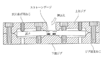
十字形試片(cruciform specimen)または一字形試片(beam or rectangular specimen)に非等方向二軸表面残留応力(σxress≠σyres≠0、σzres=0)を印加するための曲げ装置を図11と図12で示されるように考案した。
3.1. Bending to apply residual stress biaxial surface residual stress (σxres s ≠ σyres ≠ 0, σzres = 0) to cruciform specimen or beam or rectangular specimen The device was devised as shown in FIGS.
十字形試片が支持できるように溝(groove)を形成した上部及び下部ジグ(jig)の間に幅×厚み×長さが各々40×15×185mmの試片を取り付けてジグ結束ねじ(jig joining screw)を用いて固定した。以後、試片の両端に形成されたねじ孔に機械的荷重が印加できるねじ(specimen bending screw)を押し込むことによって、試片に曲げ応力を誘発させた。試片曲げ用ねじを上部あるいは下部ジグに導入することによって、試片の中央部には各々引張及び圧縮残留応力が印加され、ねじの導入変位を異にすることによって、試片の中央部に位置したストレーンゲージを通じて印加応力の大きさが調節できる。試片の中心部を強固に拘束して面外変形(out of plane deformation)を最小化させると共に、弾性曲げ応力を円滑に伝達するために図11と図12の曲型支持部(curved supporting part)が考案された。また、曲げ変形された試片の中心に押込荷重を印加する時に発生する印加応力の緩和を最小化するために、ジグ結束ねじの内部と外部に各々4個ずつ配置し、15mmの厚板試片を使用した。 Jig bundling screw (jig) by attaching a specimen of width x thickness x length 40 x 15 x 185 mm each between upper and lower jigs with grooves formed to support the cruciform specimen. It was fixed using joining screw). Thereafter, bending stress was induced in the specimen by pushing a screw (specimen bending screw) capable of applying a mechanical load into the screw holes formed at both ends of the specimen. By introducing the specimen bending screw into the upper or lower jig, tensile and compressive residual stresses are applied to the central part of the specimen, respectively. The magnitude of applied stress can be adjusted through the positioned strain gauge. In order to minimize out-of-plane deformation by firmly restraining the center of the specimen, the curved supporting part of FIGS. 11 and 12 is used to smoothly transmit elastic bending stress. ) Was devised. In addition, in order to minimize the relaxation of the applied stress generated when an indentation load is applied to the center of the bent specimen, four pieces are arranged inside and outside the jig binding screw, respectively, and a 15 mm thick plate specimen is placed. A piece was used.
3.2 試片の用意及びヌープ圧子、計装化押込試験器
3.2.1.使用した試片と試片の用意
本試験に使用した試片として、<表1>の組成と機械的物性を有するAPI X−65鋼材及びJIS S45C鋼材が用いられた。表1において後の方に記載された鋼材は機械的性質が優れるので、構造設備及び熔接材にたくさん使われている。前節で説明したように、十字あるいは一字ビーム形態の試片は機械で加工された後、試片の内部に蓄積された残留応力を除去するために熱処理が施される。
3.2 Preparation of specimen and Knoop indenter, instrumented indentation tester 3.2.1. Specimens used and preparation of specimens As specimens used in this test, API X-65 steel and JIS S45C steel having the composition and mechanical properties shown in Table 1 were used. Since the steel materials described later in Table 1 have excellent mechanical properties, they are often used for structural equipment and welding materials. As described in the previous section, a cross or single beam specimen is machined and then heat treated to remove residual stress accumulated in the specimen.
鍛造、鋳造、機械加工、及び熔接などにより生じた残留応力を除去させるために、A1点以下の適当な温度で加熱する熱処理は、応力除去焼鈍(stress relief annealing)という。残留応力が残っている金属部品をそのまま使用すれば、時間が経過するにつれて徐々にその応力が緩和されて寸法や形態が変化される場合がある。また、機械加工により一部分を除去すれば、物体の内部の応力が平衡が維持できなくなって、新たな応力平衡状態に変化されるので、変形が表れる場合が多い。このような変形を防止するためには、材料を適当な温度に加熱して残留応力を充分に除去する必要がある。通常、再結晶温度(450℃)以上、A1変態点以下で行なう。この温度で厚み25mm当たり1時間維持し、200℃/hでゆっくりと冷却させる。 In order to remove the residual stress generated by forging, casting, machining, welding, etc., heat treatment that is heated at an appropriate temperature below A 1 is called stress relief annealing. If a metal part in which residual stress remains is used as it is, the stress may be gradually relaxed over time and the dimensions and form may be changed. Further, if a part is removed by machining, the stress inside the object cannot be maintained in equilibrium and is changed to a new stress equilibrium state, so that deformation often appears. In order to prevent such deformation, it is necessary to sufficiently remove the residual stress by heating the material to an appropriate temperature. Usually, it is carried out at a recrystallization temperature (450 ° C.) or more and A 1 transformation point or less. This temperature is maintained for 1 hour per 25 mm thickness and slowly cooled at 200 ° C./h.
一般に、加熱温度が高まるほど材料は軟らかくなり、残留応力により塑性変形が起こるので応力が緩和除去される。一般的に、炭素量の多い鋼であるほど残留応力が多く、また除去が困難である。残留応力除去と共に結晶粒の微細化や組織の調節も同時にしようとする場合には、完全焼鈍やノーマライジングを行う。 In general, the higher the heating temperature, the softer the material becomes, and plastic deformation occurs due to residual stress, so that the stress is relaxed and removed. Generally, the higher the carbon content, the more residual stress and the more difficult it is to remove. Complete annealing and normalizing are performed in order to simultaneously refine the grain size and adjust the structure as well as remove residual stress.
本明細書では経験的にAPI X−65は600℃で約2時間、その他の材料は500℃で約1時間の間維持した後、炉冷を行った。残留応力除去熱処理の後、引張試験と超音波波動速度分析結果に、降伏強度、弾性係数、ポアソン(poisson)比を得た。計装化押込試験とストレーンゲージ付着のために、表面を100、200、400、600、800、1000、1500回、紙やすりで研磨した。 In this specification, API X-65 was empirically maintained at 600 ° C. for about 2 hours, and other materials were maintained at 500 ° C. for about 1 hour, followed by furnace cooling. After the residual stress relief heat treatment, yield strength, elastic modulus and poisson ratio were obtained in tensile test and ultrasonic wave velocity analysis results. The surface was polished 100, 200, 400, 600, 800, 1000, 1500 times with sandpaper for instrumented indentation testing and strain gauge attachment.
3.2.2.ヌープ圧子、計装化押込試験器
既存のヌープ圧子は、図13のように長軸と短軸との割合が7.11:1の異方性を持っているので、材料の異方性の評価に主に使われて来た。これは、材料の結晶方向に従って圧痕の長軸の長さが変化する現象から起因したものであり、これを硬度に換算すれば結晶方向との関係を導出することができる。図8で提示したように、ヌープ押込硬度を通じて残留応力との関係を提示した既存の研究もあった。
3.2.2. Knoop indenter, instrumented indentation tester The existing Knoop indenter has an anisotropy of 7.11: 1 between the major axis and the minor axis as shown in FIG. It has been mainly used for evaluation. This originates from the phenomenon that the length of the major axis of the indentation changes according to the crystal direction of the material. If this is converted into hardness, the relationship with the crystal direction can be derived. As presented in FIG. 8, there was also an existing study that presented the relationship with residual stress through Knoop indentation hardness.
しかしながら、圧痕の光学的観察の場合、誤差の素地が多くて、塑性のみを表す硬度を用いて残留応力を求める限界点が存在するので、残留応力の定量的評価に直接適用するには限界点がある。併せて、既存のヌープ圧子は微小領域で使われたので、圧痕の歪みが発生しない押込荷重範囲が6kgf以下の微細荷重領域であり、このような微小領域の押込荷重では、ロードセル(load cell)の分解能の影響による誤差が発生するようになって、正確な実験値の誘導が困難であるという問題点が発生する。したがって、本明細書では幾何学的に同一なヌープ圧子形状を有するダイヤモンド材質の圧子を製作し、これを通じて100kgf以上のマクロ(macro)な領域までの押込荷重の付加が可能となる。使用した計装化押込試験器は、Frontic Inc.のAIS 3000(最大荷重:300kgf、荷重分解能:5.6gf、変位分解能:0.1?)である。計装化押込試験の際、ロードセルで測定される荷重と変位センサで測定される変位信号を同期化させて押込荷重−変位曲線を形成する。機器のコンプライアンス効果を最小化するために、図14で示されるように圧子のホルダーが計装化押込試験器と一体型で製作された。図15は、図14に図示したヌープ圧子の測定値を示している。図16は、本発明の一実施形態で使われる計装化押込試験装置の写真である。 However, in the case of optical observation of indentations, there are many error bases, and there is a limit point for determining residual stress using hardness that represents only plasticity. There is. In addition, since the existing Knoop indenter was used in a very small area, the indentation load range in which indentation distortion does not occur is a minute load area of 6 kgf or less. With such an indentation load in such a minute area, a load cell An error due to the effect of the resolution occurs, and it is difficult to accurately derive experimental values. Accordingly, in the present specification, a diamond indenter having the geometrically identical Knoop indenter shape is manufactured, and through this, an indentation load can be applied to a macro region of 100 kgf or more. The instrumented indentation tester used was Frontic Inc. AIS 3000 (maximum load: 300 kgf, load resolution: 5.6 gf, displacement resolution: 0.1?). In the instrumented indentation test, the indentation load-displacement curve is formed by synchronizing the load measured by the load cell and the displacement signal measured by the displacement sensor. In order to minimize the compliance effect of the instrument, the indenter holder was made integral with the instrumented indentation tester as shown in FIG. FIG. 15 shows the measured values of the Knoop indenter shown in FIG. FIG. 16 is a photograph of an instrumented indentation test apparatus used in one embodiment of the present invention.
3.3.実験方法
3.3.1.最適実験条件決定
計装化押込試験を遂行するには、事前に種々の実験条件が決定されなければならない。実験値に影響を及ぼす要因は2つに大別される。第1に、分析外的な実験変数として計装化押込試験の基本データである押込荷重−変位曲線の再現性に影響を及ぼす実験変数である。押込速度及び表面の粗さ、そして押込変位などがある。圧痕面積の内部に約10個以下の結晶粒が存在する場合には、材料の平均的な変形物性が得られるよりは、変形が誘発された結晶粒の個別的な物性を表すことができる。図17のように、球形圧子でAPI X−65材料に最大150?押込んだ場合に平均結晶粒のサイズは10?と仮定する時、圧子直下塑性域の内部に数十万個、弾性域の内部には数百万個の結晶粒が存在するようになる。したがって、本明細書では多様な押込変位で反復実験を通じて、反復性の良い100?が最適の押込変位として決定された。表面の粗さと押込速度との関係を知るために、多様な粗さで押込速度を変えながら20、40、60、80、100?の押込変位での標準偏差が比較された。図18の結果に基づいて表面研磨条件が決定されて、押込速度は0.1mm/minとして決定された。
3.3. Experimental method 3.3.1. Determination of optimum experimental conditions In order to perform an instrumented indentation test, various experimental conditions must be determined in advance. Factors that affect experimental values are roughly divided into two. First, it is an experimental variable that affects the reproducibility of the indentation load-displacement curve, which is the basic data of the instrumented indentation test, as an experimental variable outside the analysis. Indentation speed and surface roughness, indentation displacement, etc. When there are about 10 or less grains within the indentation area, the individual physical properties of the crystal grains in which deformation is induced can be expressed rather than the average deformation physical properties of the material. As shown in FIG. 17, when it is assumed that the average grain size is 10? When the spherical indenter is pushed into the API X-65 material up to 150 ?, hundreds of thousands in the plastic area directly under the indenter, There are millions of crystal grains inside. Therefore, in this specification, 100? With good repeatability was determined as the optimum indentation displacement through repeated experiments with various indentation displacements. In order to know the relationship between the surface roughness and the indentation speed, the standard deviations at indentation displacements of 20, 40, 60, 80, and 100? Were compared while varying the indentation speed with various roughnesses. Surface polishing conditions were determined based on the results of FIG. 18, and the indentation speed was determined as 0.1 mm / min.
第2に、分析内的な実験変数としては、分析方法が最も大きい影響を及ぼすと見ることができる。本明細書では初期押込変位を除外した20?から100?の押込変位まで、各10?変位毎に無応力状態の荷重と残留応力が印加された状態の荷重を求めて、その差を通じて分析した。 Second, as an experimental variable within the analysis, it can be seen that the analysis method has the greatest influence. In this specification, from 20? Excluding the initial indentation displacement to 100? Indentation displacement, an unstressed load and a residual stress applied load are obtained for each 10? Displacement and analyzed through the difference. .
3.3.2.実験過程
残留応力が印加される前に、各々の試片に対して無応力状態の押込荷重−変位曲線(stress free indentation load-depth curve)を得るために、次のような実験過程が適用される。試片の用意過程を終えた十字形あるいは一字形試片を図11の残留応力発生印加装置に取り付けた後、上部ジグの中心に位置した押込孔(indenting hole)を通じて計装化押込試験を行った。押込変位100?まで0.1mm/minで押込んだ後、荷重除去率は70%まで荷重が除去された。ゼロインデックス(Zero index)は1kgとされた。角立った圧子の場合、ゼロインデックス(zero index)を機器の最小荷重である0.06kgにする場合、非線形的な区間が発生するようになる。したがって、初期接触荷重が1kgfに決定された。押込方向を各軸によって3回以上繰り返して実験が行われたた。各々の圧痕の間は相互間の塑性域の重畳を避けるために、各々3mmの間隔を置いて押込を行った 。
3.3.2. Experimental process The following experimental process was applied to obtain a stress free indentation load-depth curve for each specimen before the residual stress was applied. The After installing the cross-shaped or single-shaped specimen after the preparation process of the specimen, the instrumented indentation test is conducted through the indenting hole located at the center of the upper jig after attaching the residual stress generating device shown in FIG. It was. After pushing at a pushing displacement of 100 mm at 0.1 mm / min, the load was removed to a load removal rate of 70%. The zero index was 1 kg. In the case of a square indenter, when the zero index is set to 0.06 kg which is the minimum load of the device, a non-linear section is generated. Therefore, the initial contact load was determined to be 1 kgf. Experiments were performed with the indentation direction repeated three or more times for each axis. Indentation was carried out with an interval of 3 mm between each indentation in order to avoid overlapping of plastic zones between each other.
無応力状態の押込荷重−変位曲線を得た後、試片の表面に二軸ストレーンゲージを付着し、曲げ用ねじを回してストレーンゲージを通じて弾性変形率を得ることができる。このように得られた弾性変形率は、<数11>を通じて各軸の残留応力に換算できる。
After obtaining a stress-free indentation load-displacement curve, a biaxial strain gauge is attached to the surface of the test piece, and the elastic deformation rate can be obtained through the strain gauge by turning a bending screw. The elastic deformation rate obtained in this way can be converted into residual stress of each axis through <
Tresca降伏条件を適用して弾性限度内の残留応力が印加された。 Applying the Tresca yield condition, the residual stress within the elastic limit was applied.
また、目標変形率に到達するまで非対称的な試片の歪みを防ぐために、試片の両端に約50μεの微小な曲げ変形率を段階的に増加させた。計装化押込試験は無応力状態の押込試験と同一な条件で遂行した。 Further, in order to prevent the distortion of the asymmetric specimen until reaching the target deformation ratio, a minute bending deformation ratio of about 50 με was gradually increased at both ends of the specimen. The instrumented indentation test was performed under the same conditions as the unstressed indentation test.
計装化押込試験により得られた押込曲線を重畳させて、中心部に位置する曲線を各応力状態を代表する曲線に選択して分析した。無応力状態と最も大きい残留応力が付加された軸をx軸と決定した時、x、y軸にヌープ圧子の長軸が垂直に押込まれて得られた押込荷重−変位曲線を通じて各変位で求められる荷重差を各々ΔL1、ΔL2に決定する。 The indentation curve obtained by the instrumented indentation test was superimposed, and the curve located at the center was selected as a curve representing each stress state and analyzed. When the axis with no stress and the largest residual stress is determined as the x-axis, the displacement is obtained through the indentation load-displacement curve obtained by pushing the long axis of the Knoop indenter perpendicular to the x and y axes. The load difference to be determined is determined to be ΔL 1 and ΔL 2 , respectively.
3.3.3.直接加算検証実験
2.1で前述したように、互いに異なる軸の残留応力が押込荷重に及ぼす効果が和の関係として表現できるという仮定を証明するために、図6に示されるような実験を行った。一軸のみに200MPaの残留応力を印加された試片が押込方向を長軸が残留応力と垂直に、そして平行になるように押込まれることにより得られた押込荷重差の和が、両軸に200MPaの残留応力が印加された試片が押込まれることにより得られた押込荷重差と、比較された。
3.3.3. As described above in the direct addition verification experiment 2.1, an experiment as shown in FIG. 6 was conducted to prove the assumption that the effects of residual stresses of different axes on the indentation load can be expressed as a sum relation. It was. The sum of the indentation load difference obtained when the specimen with 200 MPa residual stress applied to only one axis is pushed in such a way that the major axis is perpendicular to and parallel to the residual stress is obtained on both axes. This was compared with the indentation load difference obtained by indenting the specimen to which a residual stress of 200 MPa was applied.
3.3.4.変換係数の割合決定実験
変換係数の割合を決定するためには、まず変換係数を決定しなければならない。<数6>で導入された変換係数α⊥、α//は、一軸に残留応力を印加した後、残留応力が印加された方向とヌープ圧子の長軸が垂直、平行になるように押込まれる時、残留応力により誘導された荷重と残留応力を連結させる変位によって決定される定数である。したがって、残留応力のサイズを変化させながら各変位でのα⊥、α//を決定する。図19は、変換係数を決定するために遂行した実験の模式図である。このように求められた各変位での変換係数は、その割合と和を通じて、残留応力の異方性係数及び残留応力を決定できる。
3.3.4. Conversion coefficient ratio determination experiment In order to determine the conversion coefficient ratio, the conversion coefficient must first be determined. The conversion coefficients α⊥ and α // introduced in <
3.3.5.モデリング検証実験
一軸引張を含んだ多様な二軸引張残留応力を印加した後、ヌープ圧子の押込方向を各軸に平行になるように押込後、得られた荷重差の割合を用いて残留応力の異方性係数を決定し、その結果を実際の残留応力の割合と比較した。また、荷重差の和を通じて残留応力の和を決定し、先に得た残留応力の割合との連立方程式の計算を通じて各軸の残留応力を測定して、実際の各軸に印加された残留応力と比較した。
3.3.5. Modeling verification experiment After applying various biaxial tensile residual stresses including uniaxial tension, and pushing the Knoop indenter so that the indentation direction is parallel to each axis, the residual stress is measured using the ratio of the obtained load difference. The anisotropy coefficient was determined and the result compared with the actual residual stress ratio. Also, determine the sum of residual stresses through the sum of the load differences, measure the residual stress of each axis through the calculation of simultaneous equations with the ratio of the residual stress obtained earlier, and apply the residual stress applied to each actual axis. Compared with.
4.有限要素解釈
ヌープ押込試験の電算模写を遂行するために、MSC. Patranで入力ファイルを生成し、ABAQUS有限要素コードを用いて有限要素解釈作業を遂行した。ヌープ圧子の幾何学的形状が二つの折り目で対称であるので、全体試片の1/4形状にモデリングした。32160個の8節レンガ状要素を用いて3次元試片形状を構成した。計算時間を減らすために次数低減積分(reduced integration)が導入されたし、有限要素解釈のためにVon Mises降伏条件を適用した。境界条件設定は、試片の底面は軸方向に固定し、中心面に沿って対称境界条件(symmetry boundary condition)を適用した。圧子は剛体(rigid body)であり、試片は炭素性挙動をするものと仮定した。計装化押込試験の有限要素解釈に使われた材料はAPI X−65で、弾性挙動は3.2.1で測定された弾性係数とポアソン(poission)比を用いて降伏強度まで使用し、一軸引張試験により求められた材料の引張曲線を用いて塑性挙動をモデリングした。
4). Finite Element Interpretation In order to perform a computer copy of the Knoop indentation test, an input file was generated by MSC. Patran, and finite element interpretation work was performed using the ABAQUS finite element code. Since the geometric shape of the Knoop indenter is symmetrical at the two folds, it was modeled as a quarter shape of the whole specimen. A three-dimensional specimen shape was constructed using 32160 8-node brick-like elements. Reduced integration was introduced to reduce computation time, and Von Mises yield condition was applied for finite element interpretation. The boundary condition was set by fixing the bottom surface of the specimen in the axial direction and applying a symmetry boundary condition along the center plane. The indenter was assumed to be a rigid body, and the specimen was assumed to be carbonaceous. The material used for the finite element interpretation of the instrumented indentation test is API X-65, and the elastic behavior is up to the yield strength using the elastic modulus and poission ratio measured in 3.2.1, The plastic behavior was modeled using the tensile curve of the material obtained by uniaxial tensile test.
試片の両端に均一な応力場を形成することによって、多様な残留応力を印加した。最大押込変位120?の変位制御により押込電算模写が行われた。
Various residual stresses were applied by forming a uniform stress field at both ends of the specimen. The indentation computer simulation was performed by the displacement control of the
5.結果及び考察
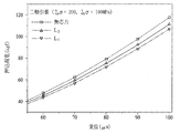
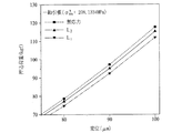
一軸引張を含んで非等方向二軸及び、等方向二軸引張残留応力を印加した後、ヌープ圧子の長軸がx、y軸に垂直に押込んで得られた押込荷重−変位曲線をそれぞれL1、L2と定義した。
5. Results and Discussion Indentation load-displacement curve obtained by applying a long axis of Knoop indenter perpendicular to the x and y axes after applying non-isobiaxial and residual biaxial tensile residual stress including uniaxial tension Were defined as L 1 and L 2 , respectively.
そして、無応力状態で得られた曲線と重畳した結果を図20乃至図22に示している。100?押込まれる時、本明細書で使用した全ての試片の押込荷重が100kgf以上の結果を表した。また、無応力状態や二軸等方向の残留応力が印加された場合、押込方向に関わらず、一定の押込荷重−変位曲線が示された。微小硬度試験やナノ押込試験でヌープ圧子の押込方向によって硬度の変化が生じることは、材料の結晶学的方向性による効果が大きいことが分かる。しかしながら、本明細書ではだいぶ深く押込むことによって、圧子の下部に多数の結晶粒を含むようになり、その結果として等方性(isotropic)の材料に押込む効果が得られた。即ち、材料の結晶学的方向の効果を除いて、残留応力の異方性効果のみを考慮することができた。マクロ範囲では、本明細書のモデリング適用において、問題が無いことを確認した。しかしながら、ナノあるいは微小硬度試験範囲では結晶学的方向性に対する考慮が必要である。また、本明細書では表面の二軸残留応力に対してのみ考慮してモデリングしたので、変位方向に対する残留応力(out of plane residual stress)の効果は表れない。したがって、今後変位方向の残留応力効果を含んだ研究が必要であり、薄膜及び微細素子への適用のためには、結晶学的異方性の効果を含んだモデリングがなされる必要がある。本章では、変換係数の決定に対する結果と、これに基づいて前述されたヌープモデリングに対する検証実験結果及びこれに対する考察が行われた。また、有限要素解釈を通じて変換係数の割合が圧子の非等方性に関連した因子であることを表す結果が提示された。 And the result of superimposing on the curve obtained in the unstressed state is shown in FIGS. When 100? Was pushed in, all the test pieces used in this specification showed a result that the pushing load was 100 kgf or more. In addition, when a residual stress in an unstressed state or biaxial equal direction was applied, a constant indentation load-displacement curve was shown regardless of the indentation direction. It can be seen that the change in hardness depending on the indentation direction of the Knoop indenter in the microhardness test or nanoindentation test has a great effect due to the crystallographic orientation of the material. However, in the present specification, by pressing deeply, a large number of crystal grains are included in the lower part of the indenter, and as a result, an effect of pressing into an isotropic material is obtained. That is, only the anisotropy effect of the residual stress could be considered except for the effect of the crystallographic direction of the material. In the macro range, it was confirmed that there was no problem in the modeling application of this specification. However, crystallographic orientation needs to be considered in the nano or micro hardness test range. Further, in this specification, modeling is performed considering only the biaxial residual stress on the surface, and therefore the effect of the residual stress (out of plane residual stress) on the displacement direction does not appear. Therefore, research including the residual stress effect in the displacement direction is required in the future, and modeling including the effect of crystallographic anisotropy needs to be performed for application to thin films and micro devices. In this chapter, the results for the determination of the transform coefficient, the verification experiment results for the Knoop modeling described above, and the discussion on this were performed. In addition, a result indicating that the ratio of the conversion coefficient is a factor related to the anisotropy of the indenter was presented through finite element interpretation.
5.1.変換係数の割合決定
変換係数の割合を決定するためには、まず変換係数を決定しなければならない。<数6>で導入された変換係数、α⊥、α//は、一軸に残留応力が印加された後、残留応力が印加された方向とヌープの長軸が垂直または平行になるように押込まれる際、残留応力により誘導された荷重と残留応力を連結させる変位によって決定される定数である。したがって、残留応力のサイズを変化させながら各変位でのα⊥、α//を決定することができる。図23は、一軸に208、389MPaの残留応力が印加された時、残留応力により誘導された荷重差が各変位で原点を通る直線にフィッティングされたものを表す。3点を通る直線は、1つに決定される。フィッティングされた直線が一直線上に近いという結果は、ビッカース圧子を用いた先行研究結果とも一致するものであって、残留応力に比例して荷重差が発生することを表す。
5.1. Determining the conversion factor ratio In order to determine the conversion factor ratio, the conversion factor must first be determined. The transformation coefficients α⊥ and α // introduced in <
図24は、各々の変位で求められた変換係数、α⊥、α//が変位によって図式化されたものである。結果から分かるように、変換係数、α⊥、α//は、押込変位が大きくなるほど増加する傾向を表している。各々の変位で直接的に変換係数の値を決定し、変換係数の割合をその割合として決定することを、今後「前進方法」と名付ける。 FIG. 24 is a diagram in which conversion coefficients, α /, α // obtained by each displacement are graphically represented by the displacement. As can be seen from the results, the conversion coefficients, α⊥ and α //, tend to increase as the indentation displacement increases. The method of directly determining the value of the conversion coefficient at each displacement and determining the ratio of the conversion coefficient as the ratio will be hereinafter referred to as “advance method”.
押込荷重差の割合を通じても、変換係数の割合の決定が可能である。 The ratio of the conversion coefficient can also be determined through the ratio of the indentation load difference.
一軸引張の場合はp=0に決定されるので、<数8>は<数12>のように表現できる。
In the case of uniaxial tension, p = 0 is determined, so <
この方法を「反転方法」と命名できる。前進方法と反転方法を通して得られた値の比較から、先に仮定した直接加算の検証が可能であり、全モデリングの妥当性が証明できる。
もし、変換係数が押込方向に関して決定され、またその比の値がモデリングによって<数12>からも同じ値が得られるならば、その比の値がモデリングのために立てた仮定(直接加算)が検証される。図25及び図26は、API X−65に関して変換係数の割合を決定したものである。図27及び図28は、ASTM A35の変換係数の割合に対する結果を示す。図29及び図30は、JIS S45Cの変換係数の割合に対する結果を示す。図31は3種の鉄鋼材料に対する変換係数の割合を各変位毎に比較した結果である。図32の結果から分かるように、押込変位に関わらず、0.34という値を中心として一定の傾向が見受けられる。
This method can be named “inversion method”. From the comparison of the values obtained through the forward method and the inversion method, it is possible to verify the direct addition assumed earlier, and prove the validity of all modeling.
If the conversion factor is determined with respect to the indentation direction and the value of the ratio is obtained from <
しかしながら、API X−65の前進方法で分析した結果は、約0.35の値を示しており、ASTM A36の場合は0.31の値を示している。但し、2つの残留応力の付加に従う実験上の誤差要因が発生した部分があると考察し、したがって、各々の材料から得たデータを総合して残留応力のサイズと荷重差との関係をまた分析した。図32に示すように、材料に関わらず残留応力のサイズに比例して押込荷重の差が発生することが分かり、このような結果により変換係数の割合を0.34に決定することができた。総3種の鉄鋼材料に限定されるが、6つの残留応力が付加され、そのサイズのみに比例するという結果を得た。また、押込変位に関わらず、その割合が一定であるという結果から、変換係数の割合がヌープ圧子と二軸に作用する残留応力の間の関係を表す1つの定数として使用できるという結論が得られた。5.3で詳述されるように、有限要素解釈を通じて変換係数の割合が圧子の非等方性と関連した関数であることを証明した。本研究結果を通じて、各軸の残留応力に比例して押込荷重差が発生し、二軸の場合は各軸により発生する押込荷重差が和と表現できることを実験的に、そして理論的に検証した。 However, the results analyzed by the API X-65 advance method show a value of about 0.35, and ASTM A36 shows a value of 0.31. However, it is considered that there is a part where experimental error factors are generated according to the addition of two residual stresses. Therefore, the relationship between the size of the residual stress and the load difference is also analyzed by combining the data obtained from each material. did. As shown in FIG. 32, it can be seen that a difference in indentation load is generated in proportion to the size of the residual stress regardless of the material. Based on such a result, the ratio of the conversion coefficient could be determined to be 0.34. . Although limited to a total of three steel materials, six residual stresses were applied, and the result was proportional to only the size. Also, from the result that the ratio is constant regardless of the indentation displacement, it can be concluded that the ratio of the conversion coefficient can be used as one constant representing the relationship between the Knoop indenter and the residual stress acting on the two axes. It was. As detailed in 5.3, it has been proved through the finite element interpretation that the ratio of the conversion coefficient is a function related to the anisotropy of the indenter. Through this research result, we verified experimentally and theoretically that an indentation load difference was generated in proportion to the residual stress of each axis, and that in the case of two axes, the indentation load difference generated by each axis could be expressed as a sum. .
5.2.ヌープモデリング検証
前述されたヌープモデリングを検証するために、残留応力印加装置を用いて一軸引張残留応力が印加された後、残留応力が印加された各軸にヌープ圧子の長軸が平行になるように計装化押込試験が遂行された。その結果、得られたΔL1とΔL2を<数13>に代入することによって、残留応力の異方性係数及び各軸の残留応力が算出される。
5.2. Knoop modeling verification In order to verify the Knoop modeling described above, after applying uniaxial tensile residual stress using a residual stress applying device, the long axis of the Knoop indenter is made parallel to each axis to which the residual stress is applied. An instrumented indentation test was performed. As a result, by substituting the obtained ΔL 1 and ΔL 2 into <Equation 13>, the anisotropy coefficient of the residual stress and the residual stress of each axis are calculated.
このように求められた残留応力の異方性係数を実際の残留応力の割合と比較し、各軸の残留応力も実際に印加された残留応力と比較した。 The anisotropy coefficient of the residual stress thus obtained was compared with the ratio of the actual residual stress, and the residual stress of each axis was also compared with the actually applied residual stress.
5.2.1.残留応力の異方性係数の決定
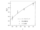
決定された変換係数の割合(p=0.34)を通じて実際のモデリングの結果が実験結果と一致するかを確認した。図33は、API X−65材料に対して多様な残留応力を印加した場合における計装化押込試験を通じて得た押込荷重差と、実際の残留応力の割合pと、を比較した図である。<数14>でフィッティングされた関数にその結果が一致するという結果は、ヌープモデリングの妥当性を見せるものである。
5.2.1. Determination of Anisotropy Coefficient of Residual Stress Through the ratio of conversion coefficient determined (p = 0.34), it was confirmed whether the actual modeling result was consistent with the experimental result. FIG. 33 is a diagram comparing the indentation load difference obtained through the instrumented indentation test when various residual stresses are applied to the API X-65 material, and the actual residual stress ratio p. The result that the result matches the function fitted by <Equation 14> shows the validity of Knoop modeling.
本明細書に使われた3種の鉄鋼材料に多様な二軸引張残留応力を印加した後、計装化押込試験により得られた押込荷重差と実際の残留応力の割合を図34に示した。押込荷重差を通じて残留応力の異方性係数pの決定が可能であることを確認することができた。 After applying various biaxial tensile residual stresses to the three types of steel materials used in this specification, the indentation load difference obtained by the instrumented indentation test and the ratio of the actual residual stress are shown in FIG. . It was confirmed that the anisotropy coefficient p of the residual stress can be determined through the indentation load difference.
5.2.2.残留応力の決定
図35は、前節で決定された変換係数、α⊥、α//の和を変位によって示すグラフである。このように各変位毎に決定された変換係数の和は、<数15>を通じて残留応力の和として計算される。
5.2.2. Determination of Residual Stress FIG. 35 is a graph showing the sum of the conversion coefficients, α⊥ and α // determined in the previous section, by displacement. Thus, the sum of the conversion coefficients determined for each displacement is calculated as the sum of residual stresses through <Equation 15>.
<数14>及び<数15>を通じて決定された残留応力の割合と和は、連立方程式を解くことにより各軸の残留応力に換算される。一軸に208MPaの引張残留応力が印加された時の残留応力の結果が例として挙げられる。図36は、一軸に208MPaの引張残留応力が印加されたAPI X−65十字試片のヌープ押込試験結果である。押込荷重差の和は、押込荷重差ΔL1とΔL2から導き出される。<数14>及び<数15>から誘導された残留応力の割合との連立方程式を解いた結果が<表2>に表されている。このような方法により計算した残留応力を図37に表した。 The ratio and sum of the residual stress determined through <Equation 14> and <Equation 15> are converted into the residual stress of each axis by solving simultaneous equations. An example is a result of residual stress when a tensile residual stress of 208 MPa is applied to one axis. FIG. 36 shows a Knoop indentation test result of an API X-65 cross specimen in which a tensile residual stress of 208 MPa is applied to one axis. The sum of the indentation load differences is derived from the indentation load differences ΔL 1 and ΔL 2 . The results of solving simultaneous equations with the ratio of residual stress derived from <Equation 14> and <Equation 15> are shown in <Table 2>. The residual stress calculated by such a method is shown in FIG.
しかしながら、変位によって決定される変換係数の和を通じて残留応力の和が誘導されるので、押込変位が変わるにつれて最終的に決定される残留応力の大きさは、影響を受けることがある。一方、残留応力の割合は、変位に関係しない一定の定数である変換係数の割合を通じて決定されるので、押込変位に関わらず一定の値を表す。したがって、残留応力の決定は、今後変換係数の物理的意味に対する考察を通じて研究が進行される部分が多い。 However, since the residual stress sum is derived through the sum of the conversion factors determined by the displacement, the magnitude of the residual stress that is ultimately determined as the indentation displacement changes may be affected. On the other hand, since the ratio of the residual stress is determined through the ratio of the conversion coefficient, which is a constant that is not related to the displacement, it represents a constant value regardless of the indentation displacement. Therefore, in the determination of residual stress, many studies will be conducted in the future through consideration of the physical meaning of the conversion coefficient.
5.3.有限要素解釈を通じて変換係数の割合の物理的な意味の考察
決定された変換係数の割合は、ヌープ圧子の非等方性と関連した関数と仮定された。実際のビッカース圧子のように等方性の圧子は押込方向に関わらず、多様な残留応力状態で1つの押込荷重−変位曲線のみを形成し、押込荷重の差は平均残留応力のサイズに比例する。しかしながら、ヌープチップ(Knoop tip)は、7.11:1の非等方性の形状によって、押込方向に従って互いに異なる押込荷重−変位曲線を形成する。特に、ヌープ圧子の長軸が最も大きい引張残留応力が印加された軸方向に垂直あるいは水平に押込まれる時、押込荷重は相対的に最も小さいか大きい傾向を表す。したがって、非等方性が大きくなると、図38に示されるようにその効果はより大きく反映されると予想できる。
5.3. Consideration of the physical meaning of the conversion factor ratio through finite element interpretation The determined conversion factor ratio was assumed to be a function related to the anisotropy of the Knoop indenter. An isotropic indenter like an actual Vickers indenter forms only one indentation load-displacement curve in various residual stress states regardless of the indentation direction, and the difference in indentation load is proportional to the size of the average residual stress. . However, Knoop tips form different indentation load-displacement curves according to the indentation direction due to the anisotropic shape of 7.11: 1. In particular, when the Knoop indenter is pushed vertically or horizontally in the axial direction to which the largest tensile residual stress is applied, the push load tends to be relatively small or large. Therefore, when the anisotropy increases, the effect can be expected to be reflected more greatly as shown in FIG.
ここでは、ABAQUS常用プログラムを通じて変形されたヌープ押込試験が遂行された。図39は、実際の無応力状態のAPI X−65にヌープ圧子で押込んだ実験結果とFEAを通じて得られた結果とを比較したものである。実際の押込試験結果と一致するか否かによって、FEAの妥当性を検証した。また、実際の実験と同一なサイズの二軸残留応力を印加した後、電算模写を通じて得られた結果が図40に表されている。5.2.1で決定されたヌープモデリングによりフィッティングされた曲線に一致する結果を表した。 Here, a modified Knoop indentation test was performed through the ABAQUS regular program. FIG. 39 shows a comparison between the experimental results obtained by pushing a Knoop indenter into API X-65 in an actual unstressed state and the results obtained through FEA. The validity of the FEA was verified by whether or not it coincided with the actual indentation test result. Further, FIG. 40 shows a result obtained through computer copying after applying a biaxial residual stress having the same size as the actual experiment. The results are shown in agreement with the curve fitted by Knoop modeling as determined in 5.2.1.
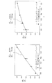
図41は、長軸と短軸との割合を3.5:1、そして14:1に変化させながら多様な二軸引張残留応力状態(p=0、0.25、0.5、1)で得られたFEA結果である。3.5:1の割合を有する場合には、変換係数の割合が実際のヌープ圧子の0.34より高い0.63の値を有する一方、非等方性が大きい14:1の場合は、0.14の値を有することを確認した。即ち、先に予想した通り、非等方性がヌープ圧子より大きくなるにつれて変換係数の割合は0に近づいて、刃物のような圧子で押込まれる時に発生する押込荷重差の割合は実際の残留応力の割合と1:1の関係を有するようになる。 FIG. 41 shows various biaxial tensile residual stress states (p = 0, 0.25, 0.5, 1) while changing the ratio of the major axis to the minor axis to 3.5: 1 and 14: 1. This is the FEA result obtained in (1). In the case of having a ratio of 3.5: 1, the ratio of the conversion coefficient has a value of 0.63 which is higher than 0.34 of the actual Knoop indenter, while in the case of 14: 1 having a large anisotropy, It was confirmed to have a value of 0.14. That is, as previously predicted, as the anisotropy becomes larger than the Knoop indenter, the ratio of the conversion coefficient approaches 0, and the ratio of the indentation load difference that occurs when the indenter is pushed with an indenter such as a blade is the actual residual It has a 1: 1 relationship with the stress ratio.
このような結果を通じて変換係数の割合は、圧子の非等方性に従って決定される定数であり、非等方性が極大化するにつれて、一軸の残留応力のみに影響を受けるようになることを予測できる。一方、等方性に近くなるほど変換係数の割合は1に近くなる。即ち、変換係数の割合は圧子の非等方性の関数で表現できる。本明細書では、3.5:1、14:1の変形されたヌープ圧子を通じてFEA電算模写を遂行し、その傾向性に対する推移のみを観察した。今後、圧子の幾何学的な形状と変換係数の割合を連結させる研究が進行される必要がある。 Through these results, the ratio of the conversion coefficient is a constant determined according to the anisotropy of the indenter, and it is predicted that as the anisotropy is maximized, only the uniaxial residual stress is affected. it can. On the other hand, the ratio of the conversion coefficient becomes closer to 1 as it becomes more isotropic. In other words, the ratio of the conversion coefficient can be expressed by an anisotropic function of the indenter. In this specification, FEA computer simulation was performed through modified Knoop indenters of 3.5: 1 and 14: 1, and only the transition with respect to the tendency was observed. In the future, research to connect the geometrical shape of the indenter and the ratio of the conversion coefficient needs to be advanced.
6.結論
ヌープ押込試験を用いて非等方向の二軸残留応力の方向性係数の決定及び各軸の残留応力を決定した。既存の等方性圧子を用いて残留応力を評価するためには、残留応力の方向性係数(p)が決定されなければならないという限界があった。しかしながら、本明細書で提示されたヌープモデリングを通じて方向性係数の決定及び各軸の残留応力のサイズまで決定可能である。
6). CONCLUSION The Knoop indentation test was used to determine the directional coefficient of biaxial residual stress in non-uniform directions and the residual stress in each axis. In order to evaluate the residual stress using the existing isotropic indenter, there is a limit that the directivity coefficient (p) of the residual stress must be determined. However, it is possible to determine the directivity coefficient and the size of the residual stress on each axis through the Knoop modeling presented herein.
1.一軸引張及び等方向を含んだ二軸引張残留応力を印加した後、ヌープ押込試験を行った。ヌープ圧子の長軸が最も大きい残留応力が印加された方向と垂直に押込まれた時における押込荷重−変位曲線の勾配は、無応力状態の押込荷重−変位曲線と比較して最も低かった。また、ヌープ圧子の長軸が最も大きい残留応力が印加された方向と平行になるように押込まれた時における押込荷重−変位曲線の勾配は、無応力状態の押込荷重−変位曲線と比較して最も高かった。 1. After applying biaxial tensile residual stress including uniaxial tension and equal direction, Knoop indentation test was performed. The slope of the indentation load-displacement curve when the long axis of the Knoop indenter was pushed perpendicularly to the direction in which the largest residual stress was applied was the lowest compared to the indentation load-displacement curve in the unstressed state. The slope of the indentation load-displacement curve when the long axis of the Knoop indenter is pushed in parallel with the direction in which the largest residual stress is applied is compared to the indentation load-displacement curve in the no-stress state. It was the highest.
2.ヌープ圧子の長軸と短軸との割合が7.11:1という非等方性の効果によって、押込方向に従って残留応力により誘導された荷重差が変わることを実験的に確認した。このような実験結果に基づいて既存のビッカースモデリングを応用してヌープモデリングを遂行した。変換係数(α⊥、α//)を通じて二軸残留応力状態での押込荷重差を数式化し、実験的に検証した。変換係数(α⊥、α//)は、残留応力と残留応力により誘導された押込荷重差とを結びつける。また、残留応力は一軸残留応力でありヌープ圧子の長軸方向であると見なされる。 2. It has been experimentally confirmed that the load difference induced by the residual stress changes in accordance with the indentation direction due to the anisotropic effect that the ratio between the major axis and the minor axis of the Knoop indenter is 7.11: 1. Based on the experimental results, Knoop modeling was performed by applying the existing Vickers modeling. The indentation load difference in the biaxial residual stress state was formulated through conversion coefficients (α⊥, α //) and verified experimentally. The conversion factor (α⊥, α //) links the residual stress and the indentation load difference induced by the residual stress. Further, the residual stress is a uniaxial residual stress and is considered to be the long axis direction of the Knoop indenter.
3.二軸残留応力状態でヌープ圧子の長軸が最も大きい残留応力が印加された方向と垂直または水平に押込まれる時に得られる押込荷重差、ΔL1とΔL2との割合は、変換係数の割合(α⊥、α//)と実際の残留応力の割合(p)の関数となる。したがって、一軸に3種の鉄鋼材料に多様な引張残留応力が印加された後、実験的に決定された変換係数(α⊥、α//)の割合が決定されることによって、押込荷重差の割合から残留応力の異方性係数(残留応力の割合=残留応力の方向性係数:p)が決定される。 3. In the biaxial residual stress state, the indentation load difference obtained when the Knoop indenter is pushed in the vertical or horizontal direction with the largest residual stress in the Knoop indenter, the ratio of ΔL 1 and ΔL 2 is the ratio of the conversion coefficient It is a function of (α), α //) and the actual residual stress ratio (p). Therefore, after various tensile residual stresses are applied to three types of steel materials on one axis, the ratio of the experimentally determined conversion coefficients (α⊥, α //) is determined to Anisotropy coefficient of residual stress (residual stress ratio = residual stress directivity coefficient: p) is determined from the ratio.
4.実験的に変換係数の割合(α⊥、α//)は、材料の種類と押込変位に関係ない定数である0.34に決定された。多様な二軸引張残留応力を印加した後、3種の鉄鋼材料に対してヌープ押込試験を遂行し、ヌープモデリングを通じて残留応力の方向性係数を決定した。実際の残留応力の割合と比較した時、誤差範囲内で一致することを確認することができた。また、変換係数の和(α⊥、α//)が残留応力の和と比例関係であることを数式的に確認し、先に決定された残留応力の割合を通じて各軸の残留応力の決定が可能であることを確認した。 4). Experimentally, the ratio of conversion coefficients (α /, α //) was determined to be 0.34, which is a constant irrespective of the type of material and indentation displacement. After applying various biaxial tensile residual stresses, Knoop indentation tests were performed on three types of steel materials, and the direction factor of residual stress was determined through Knoop modeling. When compared with the ratio of the actual residual stress, it was confirmed that they matched within the error range. Also, mathematically confirm that the sum of conversion coefficients (α⊥, α //) is proportional to the sum of residual stress, and the residual stress of each axis can be determined through the ratio of the residual stress determined previously. Confirmed that it was possible.
5.有限要素解釈を通じて、変換係数の割合(α⊥、α//)は、圧子の幾何学的形状に関連した因子であることを確認することができた。非等方性が大きくなるにつれて、変換係数の割合は0に収束するようになり、結局、押込荷重差の割合は、実際の残留応力の割合と1:1の関係を有すると仮定することができる。しかしながら、本明細書では変形されたヌープ(14:1、3.5:1)を使用することによってFEAが遂行され、解釈の結果、仮定の妥当性が確認された。 5). Through the finite element interpretation, it was confirmed that the conversion factor ratio (α⊥, α //) was a factor related to the geometry of the indenter. As the anisotropy increases, the ratio of the conversion coefficient converges to 0. Eventually, the ratio of the indentation load difference may be assumed to have a 1: 1 relationship with the actual residual stress ratio. it can. However, FEA was performed here by using modified Knoops (14: 1, 3.5: 1), and the interpretation confirmed the validity of the assumptions.
6.本明細書の実質的な適用に問題となる部分は、無応力状態の押込荷重−変位曲線の決定である。また、主残留応力の方向が決定されなければならないという問題も発生する。根本的に、計装化押込試験法による残留応力の評価は、無応力押込荷重−変位曲線との重畳を通じて同一変位で残留応力により誘導された押込荷重差を通じて定量的に残留応力を誘導するものであるので、無応力の押込荷重−変位曲線の決定は避けられないこともある。このような問題を解決するために、最近ではFEAを通じて1回の押込試験により無応力状態まで決定するための研究が遂行されている。最後に、熔接部を除く主残留応力の方向が決定されることは非常に困難である。実際の熔接部では、溶接線を基準にして主残留応力の方向が決定される。したがって、既存のストレーンゲージ法を応用して、ヌープ圧子を45゜回転しながら4回押込試験を遂行し、それから得た押込荷重差から応力を誘導し、応力間の関係から主応力のサイズを決定した後に、主応力方向を決定する研究が遂行されている。 6). The part that poses a problem for the substantial application of this specification is the determination of the indentation load-displacement curve in the unstressed state. There is also the problem that the direction of the main residual stress has to be determined. Fundamentally, the evaluation of the residual stress by the instrumented indentation test method is to induce the residual stress quantitatively through the indentation load difference induced by the residual stress at the same displacement through the superposition of the unstressed indentation load-displacement curve. Therefore, determination of a stress-free indentation load-displacement curve may be unavoidable. In order to solve such a problem, recently, research has been carried out to determine an unstressed state through a single indentation test through FEA. Finally, it is very difficult to determine the direction of the main residual stress excluding the weld. In an actual weld, the direction of the main residual stress is determined with reference to the weld line. Therefore, the existing strain gauge method is applied, the indentation indenter is rotated 45 °, the indentation test is performed four times, the stress is derived from the indentation load difference obtained, and the size of the main stress is determined from the relationship between the stresses. After determination, research has been carried out to determine the principal stress direction.
以上、本発明の実施形態を説明したが、本発明の権利範囲は、このような実施形態に制限されず、当業者が容易に変形できる範囲にも権利が及ぶ。 Although the embodiment of the present invention has been described above, the scope of the right of the present invention is not limited to such an embodiment, and the right extends to a range that can be easily modified by those skilled in the art.
Claims (9)
前記ヌープ圧子の長軸が最も大きい残留応力が印加された方向と垂直に押込まれる時の押込荷重−変位曲線の勾配と無応力状態の押込荷重−変位曲線の勾配とを比較し、ヌープ圧子の長軸が最も大きい残留応力が印加された方向と平行になるように押込まれる時の押込荷重−変位曲線の勾配と無応力状態の押込荷重−変位曲線の勾配とを比較するステップと、
を含むことを特徴とする計装化押込試験法を用いた非等方向残留応力の評価方法。Performing an instrumented indentation test using a Knoop indenter and a Vickers indenter after applying biaxial tensile residual stress including uniaxial tension and isotropic; and
Indentation load of gradients and stress-free state of the displacement curve - - indentation load when the long axis of the Knoop indenter pushed perpendicular to the largest and the direction of the residual stress is applied by comparing the slope of the displacement curve, Knoop indenter comparing a slope of the displacement curve, - indentation load of gradients and stress-free state of the displacement curve - the long axis of the pushing load when the largest residual stress pushed so as to be parallel to the direction applied
A method for evaluating non-uniform residual stress using an instrumented indentation test method characterized by comprising:
前記変換係数の割合と二軸残留応力状態でヌープ圧子の長軸が最も大きい残留応力が印加された方向と垂直又は水平に押込まれる時に得られる押込荷重差(ΔL1とΔL2)の割合とを用いて残留応力の異方性係数(残留応力の割合=残留応力の異方性係数:p)を決定するステップと、
を更に含むことを特徴とする請求項2に記載の計装化押込試験法を用いた非等方向残留応力の評価方法。Determining the ratio of the conversion factor (α⊥, α //) that connects the residual stress and the difference in indentation load induced by the residual stress according to the major axis direction of the Knoop indenter , and uniaxial residual stress;
The ratio of the conversion coefficient and the ratio of the indentation load difference (ΔL 1 and ΔL 2 ) obtained when the Knoop indenter is pushed vertically or horizontally with the direction in which the largest residual stress is applied in the biaxial residual stress state. And determining the anisotropy coefficient of residual stress using the above (the ratio of residual stress = anisotropy coefficient of residual stress: p);
The method for evaluating non-uniform residual stress using the instrumented indentation test method according to claim 2, further comprising:
Applications Claiming Priority (1)
| Application Number | Priority Date | Filing Date | Title |
|---|---|---|---|
| PCT/KR2007/000621 WO2008096914A1 (en) | 2007-02-06 | 2007-02-06 | Estimation of non-equibiaxial stress using instrumented indentation technique |
Publications (2)
| Publication Number | Publication Date |
|---|---|
| JP2010518392A JP2010518392A (en) | 2010-05-27 |
| JP5017600B2 true JP5017600B2 (en) | 2012-09-05 |
Family
ID=39681805
Family Applications (1)
| Application Number | Title | Priority Date | Filing Date |
|---|---|---|---|
| JP2009548978A Active JP5017600B2 (en) | 2007-02-06 | 2007-02-06 | Evaluation method of non-uniform directional residual stress using instrumented indentation test method |
Country Status (5)
| Country | Link |
|---|---|
| US (1) | US8214162B2 (en) |
| EP (1) | EP2118635B1 (en) |
| JP (1) | JP5017600B2 (en) |
| KR (1) | KR101152323B1 (en) |
| WO (1) | WO2008096914A1 (en) |
Families Citing this family (25)
| Publication number | Priority date | Publication date | Assignee | Title |
|---|---|---|---|---|
| JP5148459B2 (en) * | 2008-11-20 | 2013-02-20 | 日立Geニュークリア・エナジー株式会社 | Residual stress measuring device and method |
| CN102507318B (en) * | 2011-10-20 | 2013-11-13 | 中国人民解放军装甲兵工程学院 | Equi-biaxial residual stress applying device |
| KR101373059B1 (en) * | 2013-01-31 | 2014-03-11 | (주)프론틱스 | Residual stress estimation method using instrumented indentation technique |
| KR101471938B1 (en) * | 2013-01-31 | 2014-12-11 | (주)프론틱스 | Residual stress estimation method and Principal stress estimation method using Instrumented Indentation Technique |
| CN103439206B (en) * | 2013-09-13 | 2015-03-25 | 徐州工程学院 | Micro-indentation-based method for testing residual stress of tiny area of tough block material |
| CA2939787A1 (en) * | 2014-02-19 | 2015-08-27 | Osmose Utilities Services, Inc. | Automated profiling of the hardness of wood |
| KR101655566B1 (en) | 2014-11-10 | 2016-09-07 | 현대자동차주식회사 | Apparatus for safety assessement of glass materials and evaluation method thereof |
| US9921128B2 (en) | 2015-03-27 | 2018-03-20 | Exponential Business And Technologies Company | Method and apparatus for residual stress measurement through indentation with in-situ generated reference |
| RU2611698C1 (en) * | 2015-12-07 | 2017-02-28 | Федеральное государственное бюджетное учреждение науки Институт механики Уральского отделения Российской академии наук | Method for young's modulus determination for micro- and nanoparticle material |
| WO2019030970A1 (en) * | 2017-08-10 | 2019-02-14 | 住友電気工業株式会社 | Indenter comprising polycrystalline diamond, cracking load evaluation method using same, and evaluation device therefor |
| CN108132193B (en) * | 2017-12-21 | 2020-06-16 | 西北工业大学 | Method for identifying anisotropic plastic parameters of material based on spherical indentation morphology |
| WO2020017039A1 (en) * | 2018-07-20 | 2020-01-23 | 住友電気工業株式会社 | Diamond polycrystal and tool provided with same |
| CN109239316B (en) * | 2018-08-08 | 2021-05-18 | 哈尔滨工业大学(深圳) | Concrete strength monitoring method based on concrete strength monitoring device |
| CN109187180B (en) * | 2018-08-16 | 2021-08-24 | 东南大学 | Material Poisson ratio measuring method based on biaxial tensile test |
| CN110118696B (en) * | 2019-05-20 | 2021-07-23 | 吉林大学 | Method for inducing Zr-based amorphous alloy nano crystallization by combining nano indentation with fatigue load |
| CN110261021B (en) * | 2019-06-18 | 2024-04-12 | 浙江工业大学 | Rotary pressure head assembly suitable for measuring anisometric residual stress |
| CN110261020A (en) * | 2019-06-18 | 2019-09-20 | 浙江工业大学 | Suitable for measuring four pressure head components of nonequiaxial residual stress |
| US11461519B2 (en) * | 2019-06-24 | 2022-10-04 | Nanyang Technological University | Machine learning techniques for estimating mechanical properties of materials |
| CN110568001B (en) * | 2019-08-14 | 2021-09-03 | 武汉科技大学 | Method for determining stress relief annealing temperature of cold-bending thick-wall section steel corner |
| CN110595658A (en) * | 2019-09-27 | 2019-12-20 | 浙江工业大学 | Residual stress introducing device capable of keeping central position motionless |
| CN113049425B (en) * | 2021-03-19 | 2022-03-08 | 西安电子科技大学 | Method for identifying plastic mechanical parameters of metal material by adopting spherical indentation morphology |
| CN113188890B (en) * | 2021-04-29 | 2022-03-08 | 北京科技大学 | Method for measuring material surface residual stress by using nano indentation technology |
| CN114518298B (en) * | 2022-01-14 | 2023-09-29 | 东南大学 | Pressing-in calibration method for unequal double-shaft residual stress |
| CN114777979B (en) * | 2022-04-25 | 2023-10-13 | 中国石油大学(华东) | Non-uniform welding joint residual stress test method based on indentation energy difference method |
| JP2024115598A (en) * | 2023-02-15 | 2024-08-27 | Jfeスチール株式会社 | Manufacturing method of metal plate structure |
Family Cites Families (16)
| Publication number | Priority date | Publication date | Assignee | Title |
|---|---|---|---|---|
| US5003982A (en) * | 1989-07-28 | 1991-04-02 | Johns Hopkins University | Dynamic indentation system |
| JP2731864B2 (en) * | 1989-09-05 | 1998-03-25 | 新日本製鐵株式会社 | Indentation type hardness tester |
| CA2118507A1 (en) * | 1992-04-21 | 1993-10-28 | Kyriacos Athanasiou | Arthroscopic indenter and method for using the same |
| US5432595A (en) * | 1993-07-13 | 1995-07-11 | Pechersky; Martin J. | Method for measuring residual stresses in materials by plastically deforming the material and interference pattern comparison |
| US6134954A (en) * | 1996-04-15 | 2000-10-24 | Massachusetts Institute Of Technology | Depth sensing indentation and methodology for mechanical property measurements |
| US6155104A (en) * | 1998-05-26 | 2000-12-05 | Subra Suresh | Method and apparatus for determining preexisting stresses based on indentation or other mechanical probing of a material |
| JP2001349815A (en) * | 2000-06-07 | 2001-12-21 | Bridgestone Corp | Method and instrument for measuirng hardness and elastic modulus of thin film |
| US6568250B1 (en) * | 2000-09-22 | 2003-05-27 | International Business Machines Corporation | Apparatus and method for determining residual stress |
| JP3702203B2 (en) * | 2001-01-12 | 2005-10-05 | ドンイル,クォン | Press-in testing machine for continuous press-in test, physical property measuring method and physical property calculating method using the same |
| US6470756B1 (en) * | 2001-02-23 | 2002-10-29 | The Regents Of The University Of California | System and method for measuring residual stress |
| KR100416723B1 (en) | 2002-04-04 | 2004-01-31 | (주)프론틱스 | Apparatus for determining residual stress, method for determining residual stress data using it, residual stress determining method using it and recording medium thereof |
| US7165463B2 (en) * | 2003-10-14 | 2007-01-23 | Northwestern University | Determination of young's modulus and poisson's ratio of coatings from indentation data |
| KR100491295B1 (en) * | 2004-11-09 | 2005-05-24 | (주)프론틱스 | Evaluating method of the fracture toughness using the continuous indentation method |
| KR100517857B1 (en) | 2004-12-16 | 2005-09-30 | (주)프론틱스 | Evaluating method of the residual stress determining method using the continuous indentation method |
| TWI282858B (en) * | 2005-12-30 | 2007-06-21 | Ind Tech Res Inst | Nano-indentation ultrasonic detecting system and method thereof |
| JP4328349B2 (en) * | 2006-11-29 | 2009-09-09 | 株式会社日立製作所 | Residual stress measurement method and apparatus |
-
2007
- 2007-02-06 US US12/526,166 patent/US8214162B2/en active Active
- 2007-02-06 WO PCT/KR2007/000621 patent/WO2008096914A1/en active Application Filing
- 2007-02-06 KR KR1020097016242A patent/KR101152323B1/en active IP Right Grant
- 2007-02-06 JP JP2009548978A patent/JP5017600B2/en active Active
- 2007-02-06 EP EP07708771.6A patent/EP2118635B1/en active Active
Also Published As
| Publication number | Publication date |
|---|---|
| KR101152323B1 (en) | 2012-06-11 |
| KR20100004940A (en) | 2010-01-13 |
| WO2008096914A1 (en) | 2008-08-14 |
| JP2010518392A (en) | 2010-05-27 |
| US20100198530A1 (en) | 2010-08-05 |
| EP2118635B1 (en) | 2019-10-09 |
| US8214162B2 (en) | 2012-07-03 |
| EP2118635A1 (en) | 2009-11-18 |
| EP2118635A4 (en) | 2011-11-09 |
Similar Documents
| Publication | Publication Date | Title |
|---|---|---|
| JP5017600B2 (en) | Evaluation method of non-uniform directional residual stress using instrumented indentation test method | |
| Peng et al. | Spherical indentation method for estimating equibiaxial residual stress and elastic–plastic properties of metals simultaneously | |
| Xing et al. | An experimental study of residual stress induced by ultrasonic shot peening | |
| US20160258852A1 (en) | Contact Mechanic Tests using Stylus Alignment to Probe Material Properties | |
| Wiederhorn et al. | Mechanical properties | |
| Rao et al. | On characterisation of local stress–strain properties in friction stir welded aluminium AA 5083 sheets using micro-tensile specimen testing and instrumented indentation technique | |
| Kim et al. | An indentation method for evaluation of residual stress: Estimation of stress-free indentation curve using stress-independent indentation parameters | |
| Dias et al. | Determination of stress-strain curve through Berkovich indentation testing | |
| Kim et al. | Estimation of principal directions of Bi-axial residual stress using instrumented Knoop indentation testing | |
| Ahn et al. | Directionality of residual stress evaluated by instrumented indentation testing using wedge indenter | |
| Acevedo et al. | Residual stress measurement techniques for Ti6Al4V parts fabricated using selective laser melting: State of the art review | |
| Gutiérrez-Moizant et al. | Experimental verification of the boundary conditions in the success of the Brazilian test with loading arcs. An uncertainty approach using concrete disks | |
| Ghosh et al. | Study of damage and fracture toughness due to influence of creep and fatigue of commercially pure copper by monotonic and cyclic indentation | |
| Xue et al. | Approach for obtaining material mechanical properties in local region of structure based on accurate analysis of micro-indentation test | |
| He et al. | Assessment of the Local Residual Stresses of 7050-T7452 Aluminum Alloy in microzones by the instrumented indentation with the Berkovich Indenter | |
| Teng et al. | Finite element analysis of circular patch welds | |
| CA2916042A1 (en) | Contact mechanic tests using stylus alignment to probe material properties | |
| François | Structural components: mechanical tests and behavioral laws | |
| Lee et al. | A dual indentation method for evaluating intrinsic material properties of metals under residual stress | |
| Mahmoudi et al. | Spherical Indentation, Part II: Experimental Validation for Measuring Equibiaxial Residual Stresses | |
| Syngellakis et al. | Weld zone material characterisation based on spherical indentation data | |
| Elmisteri et al. | Mechanical properties evaluation for engineering materials utilizing instrumented indentation: Finite element modelling approach | |
| Choi et al. | Determination of Residual Stress Directionality by Instrumented Indentation Testing Using Anisotropic Indenter | |
| Mirsayapov | A study of stress concentration zones under cyclic loading by thermal imaging method. | |
| HUIWEN | Evaluation of Non-equal Biaxial Residual Stress Using Modified Berkovich Indenter in Nano Scale |
Legal Events
| Date | Code | Title | Description |
|---|---|---|---|
| A131 | Notification of reasons for refusal |
Free format text: JAPANESE INTERMEDIATE CODE: A131 Effective date: 20111101 |
|
| A521 | Request for written amendment filed |
Free format text: JAPANESE INTERMEDIATE CODE: A523 Effective date: 20120131 |
|
| TRDD | Decision of grant or rejection written | ||
| A01 | Written decision to grant a patent or to grant a registration (utility model) |
Free format text: JAPANESE INTERMEDIATE CODE: A01 Effective date: 20120417 |
|
| A01 | Written decision to grant a patent or to grant a registration (utility model) |
Free format text: JAPANESE INTERMEDIATE CODE: A01 |
|
| A61 | First payment of annual fees (during grant procedure) |
Free format text: JAPANESE INTERMEDIATE CODE: A61 Effective date: 20120509 |
|
| R150 | Certificate of patent or registration of utility model |
Ref document number: 5017600 Country of ref document: JP Free format text: JAPANESE INTERMEDIATE CODE: R150 |
|
| FPAY | Renewal fee payment (event date is renewal date of database) |
Free format text: PAYMENT UNTIL: 20150622 Year of fee payment: 3 |
|
| R250 | Receipt of annual fees |
Free format text: JAPANESE INTERMEDIATE CODE: R250 |
|
| R250 | Receipt of annual fees |
Free format text: JAPANESE INTERMEDIATE CODE: R250 |
|
| R250 | Receipt of annual fees |
Free format text: JAPANESE INTERMEDIATE CODE: R250 |
|
| R250 | Receipt of annual fees |
Free format text: JAPANESE INTERMEDIATE CODE: R250 |
|
| R250 | Receipt of annual fees |
Free format text: JAPANESE INTERMEDIATE CODE: R250 |
|
| R250 | Receipt of annual fees |
Free format text: JAPANESE INTERMEDIATE CODE: R250 |
|
| R250 | Receipt of annual fees |
Free format text: JAPANESE INTERMEDIATE CODE: R250 |
|
| R250 | Receipt of annual fees |
Free format text: JAPANESE INTERMEDIATE CODE: R250 |
|
| R250 | Receipt of annual fees |
Free format text: JAPANESE INTERMEDIATE CODE: R250 |
|
| R250 | Receipt of annual fees |
Free format text: JAPANESE INTERMEDIATE CODE: R250 |