JP5016166B2 - Apparatus and method for immersion surface treatment - Google Patents
Apparatus and method for immersion surface treatment Download PDFInfo
- Publication number
- JP5016166B2 JP5016166B2 JP2001173363A JP2001173363A JP5016166B2 JP 5016166 B2 JP5016166 B2 JP 5016166B2 JP 2001173363 A JP2001173363 A JP 2001173363A JP 2001173363 A JP2001173363 A JP 2001173363A JP 5016166 B2 JP5016166 B2 JP 5016166B2
- Authority
- JP
- Japan
- Prior art keywords
- housing
- fingers
- finger
- groove
- processing
- Prior art date
- Legal status (The legal status is an assumption and is not a legal conclusion. Google has not performed a legal analysis and makes no representation as to the accuracy of the status listed.)
- Expired - Lifetime
Links
Images


Classifications
-
- B—PERFORMING OPERATIONS; TRANSPORTING
- B23—MACHINE TOOLS; METAL-WORKING NOT OTHERWISE PROVIDED FOR
- B23K—SOLDERING OR UNSOLDERING; WELDING; CLADDING OR PLATING BY SOLDERING OR WELDING; CUTTING BY APPLYING HEAT LOCALLY, e.g. FLAME CUTTING; WORKING BY LASER BEAM
- B23K9/00—Arc welding or cutting
- B23K9/0061—Underwater arc welding
Description
【0001】
【発明の属する技術分野】
本発明は、一般的に液没加工面を処理する装置及び方法に関し、特に液没加工面から液体を排除して、溶接用トーチ、加熱装置あるいはストレス緩和装置のような処理装置周りに局部乾燥領域をもたらす装置及び方法に関する。
【0002】
【従来の技術】
水面下又は液没環境のもとでの溶接、熱的ストレス付与等の処理用途は、処理すべき加工面から水を排除できるように、処理ヘッド周りに局部乾燥領域が必要となる。例えば、水没溶接では、溶融金属と付近の加熱ゾーンから水を排除して、過剰な酸化、早期冷却、その他の欠陥を防がなければならない。溶接ヘッド周辺の水を局部的に排除し、溶融金属プールのために化学的に不活性な雰囲気を形成するために、代表的には不活性ガスが使用される。しかしながら、多くの水没用途においては、加工面は、滑らかでないか、又は規則的でなく、新しい又は研磨されていない溶接パスが加工面に形成された後は、特にそうである。これらの場合、水排除装置は、加工面外形の高低に対し、しばしば急激な変化に対しても、完全に対応できる十分な排除範囲を有さねばならない。
【0003】
溶接の用途については、溶接トーチ周りの水の排除、及び加熱あるいは低温処理領域からの蒸気の排除は、低いガス流量で最も良く達成でき、これは、実行するのに高価であり、気泡過多形成による視認性不良、あるいは、液体金属層や局部乾燥ゾーン内の他の制御状態の乱れ、という高流量のもとで知られている問題を回避するものとなる。しかしながら、制限されたコンプライアンスシールが不充分な範囲のものであり、その周辺の一部で加工面から離れるような場合、あるいは、トーチ不活性ガスカップ内から水を排除するのにコンプライアンスシールなしで環状ガス流のみの設計を用いる場合には、面外形の大きな変化に対しては、十分な水排除を維持するために高いガス流量を使用しなければならない。この両方の場合、増大したギャップを横切って最低限の圧力差を維持し、水に向かって外向きのガス流が維持され、水または混合相が溶接処理ゾーンに逆流しないようにするための最低限必要なガス流がギャップを横切って維持されるようにするために、高い流出量が必要とされる。コンプライアンスシールとガス流ギャップの利点を組み合わせた設計は、いずれかの設計のみと対比して増大したコンプライアンス範囲をもつと期待できるが、この組み合わせ設計は、これら各設計が個々に有するのと類似した問題を依然として持っている。
【0004】
水没用途のための水その他の液体排除装置としての現存の設計は、3つの基本作動原理、すなわち、(1)例えば、溶接環境では、トーチ末端周りに設けたカップ型ガス充填部品のように、加工面とアプリケーターヘッドとの間のギャップを機械的にシールすること、(2)作動面とアプリケーターヘッドとの間の、比較的小さく制御された幅のギャップにわたってガスを流出させること、(3)あるいは、拡がり形状の水/ガス円錐を、制御されたギャップを横切って流出させ、作動面に対し円錐状接触領域内にある水を排除すること、という作動原理を有する。
【0005】
これら原理を組み合わせた種々の設計例は、流れる水またはガスの同心的な多段円錐に対するガス透過性のコンプライアンスシールを含むものである。ゴム状エレメントはコンプライアンスを与えるために変形されるものであり、このエレメントは、(塑性変形する前または完全に圧縮される前において)歪み範囲が限られており、同時に、排除量を大きくするためには非常に大きな力が必要になり、面形状に沿って所望の位置を維持するには、アプリケーターヘッドの操作によりこの力を克服しなければならないので、コンプライアンスシールに頼るこの設計は、本質的に実用上の作用範囲が限定される。力に対する要求と高い排除量は、より薄い、より軟らかい屈曲性シールエレメントを採用することにより、ある程度は減じることができる。しかしながら、これらの薄いエレメントは、使用中の不慮の過負荷により、又は処理操作中、あるいは、加工面の凹凸部や不連続部上を滑動する間の引き裂きにより、機械的損傷を受ける傾向が強くなる。
【特許文献1】
米国特許第4172974号 1979年10月発行
【特許文献2】
米国特許第5750954号 1998年5月発行
【特許文献3】
米国特許第5852271号 1998年12月発行
【特許文献4】
米国特許第6255616号 2001年7月発行
【0006】
ギャップを通して水やガス流を積極的に流すことに頼る設計は、局部外形が変化したり、アプリケータヘッドが傾斜したりした場合にギャップ差を生じ、結果としてギャップ周辺においてガス流の差をもたらすことが予期されるため、限界がある。ギャップが一つの領域で大きい場合、特に溶接において、ガスの流量と流速も大きくなり、ギャップの小さい残りの周辺領域の流量と流速が犠牲になる。ギャップの小さい領域で、流量が減少した場合、流量は、水/ガスの界面におけるサージングなしに水を押し返し、あるいは、極端な場合には、アプリケータヘッドハウジング内の乾燥溶接ゾーンまたは処理ゾーンへの水の逆流を抑制するのに最低限必要とされるものより低くなる。
【0007】
特に、現存の水排除装置は、基体表面の溝について使用する場合には、装置と溝の最も低い部分の間の流れ間隙を充填して間隙を制限するとか、「フローカーテン」型の装置の場合には、溝から離れているところで必要とされる量よりも多い流量を溝に差動的に供給する、といった装備がないので、この用途に対しては本質的に不充分である。その結果として、内部流れを用いて水を例えば溶接のような処理を妨げるレベル以下にまで排除する公知の装置の能力は、最良の場合でも制限があり、最悪の場合、効果はない。更に、深い溝内から水を取り除くためには、これら装置の効果には限界がある。これら装置が、溝の深さ限界能力内で溝の水を排除するために使用される場合においても、溝から離れた領域内で起こる流れは、溝自体にとって十分な流れを得るのに必要な量よりも多くなるため、パージ流体の浪費を生じる。最悪の場合、これら装置は、深い溝から水を排除するのに全く効果がない。
【0008】
【発明が解決しようとする課題】
本発明の好ましい実施形態では、装置内からの過度に高いガス流を用いることなく、液没基体材料に形成された浅い、または深い溝から液体、例えば水を排除する装置および方法が提供される。このような高ガス流は、例えば溶接のような処理を、溶融金属プールを冷却するか移動させるかして妨害するか、または、装置周囲に液体/ガス境界位置を形成するために通常使われる不活性ガスを浪費することになる。ガス流は、遂行中の処理を妨害しないように、十分に低くなければならないが、しかしながら排除装置と加工面との間のギャップ周りの液体を効果的に排除するほど十分に高くなければならない。蒸気は、高温または液状の金属と反応しがちであり、溶接の欠陥を起こす傾向があるので、過剰液体蒸気もまた、処理ゾーンへの進入を防止しなければならない。
【0009】
【課題を解決するための手段】
上述したことを達成するために、本発明の好ましい実施形態において、複数の、薄い平坦なフィンガーが、排除装置の対向する端部に平行で該端部に位置するように設けられ、該装置は、溝のような加工面領域に沿って溝の方向に、かつフィンガーに平行に移動可能であり、このフィンガーは、排除装置の先端縁および後端縁に隣接する溝の幾何学的形状に対応するように、異なる幾何学的形状を維持する。好ましくは、これらの薄い平坦なフィンガーは、装置の相対向する端部の各々において、横並びの関係で配置され、突出位置にピボット運動するように、一端がばね付勢されている。結果として、各フィンガーの自由端すなわち末端は、加工面に接する方向に付勢され、排除装置内から流体を実質的に排除するシールを形成する。装置の側部も同様に、加工領域または溝にまたがる表面との間でシールを形成する。フィンガーの末端に実質的な湾曲部を形作ることで、フィンガーの端部は、ばね付勢力のもとで、溝の外形面に追従し、加工面との間で十分な機械的シールを形成する。例えば、溶接ヘッドのような処理ヘッドは、フィンガーの先行側の列と後端側の列との間で装置内に位置し、処理用ガスまたはパージガスの適当な流れが形成されて、制御された間隙スペース内からあらゆる水を排除する。
【0010】
本発明のさらに好ましい実施形態では、互いに、かつ、加工面に沿う排除装置の移動方向に平行に延びる複数のブレードすなわちフィンガーが、該排除装置の先端縁および後端縁において並進運動可能に取り付けられる。特に、並進フィンガーは、全体とし移動方向に細長く、装置の移動方向に対して横方向に延びる一対のガイドロッド上にフィンガーを取り付けるための、間隔をもった垂直スロットを有する。ばね、好ましくは、中央の横方向に延びるビームと前方向および後方向に延びるリーフばねとを有するばねが、ハウジング上部に対するシールを形成し、ばねの末端部がフィンガーの上面に係合して、加工面に接触する下方方向にフィンガーを付勢する。フィンガーは垂直方向に並進運動するだけでなく、加工面の不規則性に対処するため、横方向軸周りに傾斜できる。このように、フィンガーの下部の細長い面は、加工面に係合し、ハウジング内から液体を実質的に排除するシールを形成する。並進ブレード間のギャップ、およびリーフばね間のギャップは十分に小さく、排除装置内のガス圧が、排除領域への液体漏洩を防止する。
【0011】
本発明の更に好ましい形態では、例えば、溶接ヘッド、またはトーチのような処理装置は、ばね付勢されたベローズを介して水排除装置に結合され、それによって、トーチヘッドと排除装置との間のトーチ軸に沿った相対的運動が可能になる。ベローズばねは、排除装置ハウジングを加工面に押しつける。使用の際、トーチヘッドは、操作装置あるいはロボットアームに取り付けられ、アームは、ベローズばねの付勢のもとで加工面に対し、排除装置を保持するための反力を与える。このように、前述した、ピボット運動あるいは並進フィンガーのいずれかを使用することにより、トーチヘッドは、加工面に対して適所に維持されることができる。例えば、自動アーク電圧制御溶接装置において、溶接ヘッドと、加工面との間に一定の電圧を維持することが望ましい。これは、典型的には、トーチヘッドと加工面との間のアーク全体にわたって電圧低下量に応じたサーボ制御により維持される。結果として、コンプライアンスシールとピボット運動または並進フィンガーと、排除装置内の高ガス圧とを使用することで加工面を液体のない状態に保ちながら、トーチヘッドをモーター駆動により加工面に対して接近しまたは遠ざかる方向に動かすことができる。
【0012】
本発明の好ましい実施形態では、溝のある液没加工面を処理する装置は、開口部を有し加工面に対し可動である閉ハウジングと、前記開口の少なくとも一部の周りの位置で、引込位置と前記ハウジングから突出した位置との間を、互いに独立に、かつ、全体として平行な軸線まわりにピボット運動可能なように、前記ハウジングによって支持された個々のフィンガーの列と、を備え、このフィンガーは、末端部に、前記軸線から間隔をおいて位置し、フィンガーの突出位置で溝に係合するか又は溝に近接して置かれる先端部を有し、ハウジングが表面に対し移動するのに伴なって、フィンガーが互いに実質的に独立して、突出位置にピボット運動して、フィンガー先端が加工面の溝に追従するようにする手段と、ハウジングによって支持され、フィンガーの内部にあり、開口部を通して、表面を処理する加工ヘッドが設けられている。
【0013】
本発明のさらに好ましい実施形態では、溝を含む液没加工面を処理する装置であって、開口部を有し加工面に対して可動な閉ハウジングと、該開口部の少なくとも一部の周りの位置で引込位置とハウジングから突出する位置との間を、互いに実質的に独立して並進運動可能なように互いに横並びの関係で該ハウジングによって支持される個々のフィンガー列と、を備え、該フィンガーは、並進運動方向に対しほぼ直角の方向に細長く、フィンガーの突出位置において溝に係合するかあるいは近接して置かれる長い端縁を有し、互いに実質的に独立して突出位置にフィンガーを移動させることにより、ハウジングが前記表面に対して移動するに伴なって、前記端縁が加工面の溝に追従できるようにする手段と、ハウジングによって支持され、フィンガーの内側にあって、開口部を通して、前記表面を処理する加工ヘッドと、が設けられた装置が提供される。
【0014】
本発明のなお一層好ましい実施形態では、溝を含む液没加工面を処理する装置であって、開口部を有し加工面に対し可動な閉ハウジングと、該開口部の少なくとも一部の周りの位置で、引込位置とハウジングから突出する位置との間を互いに実質的に独立して運動するように、該ハウジングによって支持される個々のフィンガーの列と、を備え、該フィンガーは、突出位置において、前記溝に係合するかあるいは近接しておかれる表面を有し、該フィンガーを互いに実質的に独立して突出位置に移動させ、ハウジングが表面に対し移動するのに伴なって、前記表面が加工面の溝に追従するようにする手段と、ハウジングに接近および遠ざかる方向に該ハウジングに対して運動可能にハウジングに取り付けられた加工ヘッドと、が設けられた装置が提供される。
【0015】
本発明の更に好ましい実施形態では、閉ハウジングと、開口部と、該ハウジングによって支持される加工ヘッドと、開口部の少なくとも一部の周りで、引込位置とハウジングから突出する位置との間を、互いに実質的に独立してピボット運動可能に支持された個々のフィンガーの列とを含み、液没加工面の溝を処理する装置において、該加工面から流体を排除する方法であって、ハウジングに対して互いに実質的に独立してフィンガーをピボット運動させて、該フィンガーの先端を突出位置において前記溝に係合させ、フィンガーが溝の外形に追従し互いに独立して移動可能な状態で、加工面に沿って装置を前進させ、ハウジング内の加工ヘッドにさらされた加工面から液体を実質的に排除し、フィンガーが加工面に沿って継続的に係合する状態で、装置が該加工面に沿って前進させられるのに伴い、開口部を通じて加工面を処理するように加工ヘッドを作動させることからなる方法が提供される。
【0016】
本発明の更に好ましい実施形態では、閉ハウジングと、開口部と、ハウジングに支持される加工ヘッドと、ハウジングの少なくとも一部の周りで引込位置とハウジングから突出した位置との間を、互いに実質的に独立して並進運動して、加工面の溝に沿って長い表面が係合するように支持された個々の細長いフィンガーの列を含み、液没加工面の溝を処理する装置において、加工面から流体を排除する方法であって、ハウジングに対して互いに実質的に独立してフィンガーを並進させて、該フィンガーの長い表面が、突出位置において前記溝に係合できるようにし、フィンガーが、前記溝の外形に追従し互いに独立して移動可能な状態で、加工面に沿って装置を前進させ、ハウジング内の加工ヘッドにさらされた加工面から流体を実質的に排除し、フィンガーが、加工面に沿って継続的に係合した状態で装置が加工面に沿って前進するのに伴なって、開口部を通して加工面を処理するように加工ヘッドを作動させる、段階を含む方法が提供される。
【0017】
本発明の更に好ましい実施形態では、閉ハウジングと、開口部と、該ハウジングに結合された加工ヘッドと、開口部の少なくとも一部の周りで引込位置とハウジングから突出した位置との間を、互いに実質的に独立して運動可能なように支持された、個々のフィンガーの列とを含み、液没加工面の溝を処理する装置において、加工面から流体を排除する方法であって、互いに実質的に独立してハウジングに対してフィンガーを突出させて、該フィンガーの表面が突出位置において前記溝に係合できるようにし、フィンガーが前記溝の外形に追従し互いに独立して可動な状態で、加工面に沿って装置を前進させ、ハウジング内の加工ヘッドにさらされた加工面から流体を実質的に排除し、フィンガーが加工面に沿って継続的に係合している状態で、装置を該加工面に沿って前進させるのに伴なって、開口部を通して加工面を処理する加工ヘッドを作動させ、処理ヘッドとハウジングとの間に相対的運動を行わせる、段階を含む方法が提供される。
【0018】
【発明の実施の形態】
さて、図面、特に図1を参照すると、水没または液没処理用途の排除装置が全体を10で示されている。水没装置は例えば溶接、水噴射洗浄、熱をベースとする表面残留応力改良、その他の用途のような種々の用途で使用できるものである。しかし、本説明は、本発明を水没溶接という特定の用途ついて説明しているが、本発明は水没溶接に限定されず、他の用途にも及ぶということが認識できるであろう。
【0019】
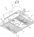
この装置10は、上部と側部および端部が閉じられたハウジング12を有し、その側部と端部の範囲における下側の面に沿って開口部13を有する。ハウジング12は、例えば溶接トーチのようなアプリケータヘッド14を有する。アプリケータヘッド14は、ヘッド14の先端がハウジング12の下方開口部を通して加工面を処理する位置、すなわち加工面の溝を溶接する位置に置かれるように、ハウジング12を通して延びている。図2に示すように、ハウジングは、溶接トーチ14を囲むマニホルド18を含み、パージガスが入口20を通ってハウジング12へ流れ、ハウジング開口部内の排除ゾーンに進入できるようにする。
【0020】
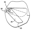
ハウジングは、側壁22と端壁24を有する。溝に沿って可動である装置10を用いて溝に沿って溶接を行うとき、端壁24は、先行側の端壁及び後側の端壁24を構成する。ハウジング12内では、個別にまたは独立して可動な個別フィンガー26の先行側および後側の列が形成される。各列のフィンガーは、互いに横並びの関係で平行に置かれる。すなわち、フィンガーの群は、装置10の相対向する端に置かれ、全体として平行な軸周りにピボット動可能である。図1に最も良く示されているように、フィンガー26は装置10の長さ方向に、すなわち端壁24の方向または移動方向に細長い形状である。図3に最も良く示されるように、各フィンガーは、その末端に大きな湾曲状先端30を有する。各フィンガー26の反対側の端は、隣接するフィンガー26を通る取り付け用ロッド32の手段によりハウジングにピボット取り付けされる。各フィンガー26を図3に鎖線で示す引込位置と、図3に実線で示す位置との間でピン32の軸線まわりにピボット動させるため、個別にばね34が設けられる。フィンガー26の横面が互いに密接するのを確実にするため、ばね34はフィンガー26の近位端にある凹部に位置させることができる。フィンガー26は、フィンガーの湾曲した端30が係合する面の形状に応じて、引込位置と突出位置との間で取付ピン32周りに独立してピボット動可能であるというだけで十分であろう。
【0021】
図4には、溝42、例えば直線的に延びる溝を備える加工面40が示される。
ハウジングの中心に位置するフィンガー26は、ばね34の付勢力のもとで、引込位置から溝42内に突出して、装置10の対向する端部で溝の表面形状に対し、実質的なシールを形成する。溝42の外側にあるフィンガー26においては、それら末端30が溝42にまたがって加工面に係合する。フィンガーの少なくとも湾曲部分は、隣接するフィンガー間の摩擦を減じるため被覆するか、または硬化させることができ、これによって、各フィンガーは、その引込位置と突出位置に対する位置が、該フィンガーの湾曲した末端30が係合する外形面の深さで決まることになる。大きな湾曲は、フィンガーが、外形の局部的変化に対して自在にスライドし、装置が横に、すなわち多重パスデポジットに隣の溶接ビードをデポジットする位置に向けて動く時、溝縁から登り出ることが可能となる。フィンガーの長さは、溝に沿うハウジング10の主な移動方向に平行に向けられる。
【0022】
装置の側壁22は、その下線に沿って、溝42をまたぐ作動面40に係合し、シールするための適当な順応シール44を有してもよい。ハウジング10が溝に沿って溝の方向に、すなわち、フィンガー26の長さ方向の範囲に平行に移動するのに伴なって、個々のフィンガーは、その末端が、溝42を含む加工面外形に沿って係合するように付勢される。注目すべき点は、フィンガーの先行側および後側の列がともに溝に係合することである。このように、フィンガーの先行側の列および後側の列は、装置10の側壁22と共に、装置10開口部13内の排除領域を形成し、開口部への水の侵入を禁止し、トーチの作動を可能にする。パージされたガスも又、排除領域内から外に水を維持する助けとなる。
【0023】
次に、図6、図7に示す本発明の好ましい実施形態について言及すると、排除装置の別の形態の装置が、全体を60で示されており、この装置は、(図に示されていないが先の実施形態にあったアプリケータヘッド14と類似するアプリケータ)を取り付けるためのマニホルド64を有するハウジング62を含む。加工面に沿った排除装置の移動方向にある先行端縁はチャンネル、例えば、水排除並進ブレードすなわちフィンガー68を収めるためのチャンネル66を備える。ハウジング62の相対向する端部の各々にあるフィンガー列68は、互いに横並びの平行関係で、加工面に沿った装置の移動方向に平行に取り付けられる。側壁70は、ハウジング62の両側と並進フィンガー68を囲む。
【0024】
図7に最も良く示されるように、各フィンガー68はハウジング62の移動方向に長円形であることが好ましく、直線状の上下縁または表面を円みをつけた両端部で接続した形状を有する。各フィンガーは、一対の、長さ方向に間隔を隔てて垂直方向に延びるスロット72を有する。スロット72は、ハウジング62の両側部間に横方向に延びるロッド74を受ける。したがって、フィンガー68の平坦な側部は互いに係合し、フィンガーは、垂直スロット72とロッド74から与えられる制限内で、垂直並進運動自在である。フィンガー68は又、ハウジング62の移動方向に垂直面内において傾斜運動が自在である。
【0025】
フィンガー68の下部縦方向縁部76を加工面に沿って係合状態に維持するため、ばね78がチャンネル66内でハウジング62に固定され、加工面の方向に向けて各フィンガー68を付勢する。好ましい実施形態では、ばね78は、ハウジング62の側面から側面まで横方向に延びてその内部表面をシールする中央ビーム80を有し、複数のそれぞれ前方および後方に延びるリーフばね82、84を有する。ばね82,84の末端は、スロット72の真上の位置でフィンガー68の上面に係合し、フィンガー68を均等に下向きに付勢するが、フィンガー68が互いに矢印86方向のいずれかに傾斜することを許容する。
【0026】
チャンネル66とフィンガー68の間の間隔が、小さな間隙をもたらし、この間隙が、その程度範囲で、ハウジング62内から流体を排除する一方、フィンガー68は、ばね78と組み合わされて、ハウジング内のガス圧とともに、ハウジング内部から液体を排除する。すなわち、横方向に隣接するリーフばね82、84間のギャップおよび隣接するフィンガー68間のギャップを通してのあらゆる漏洩路は十分に小さく、従ってハウジング内の圧力がギャップを通るガス流出をもたらし、ハウジング内から流体を排除する。その為、フィンガー68は、加工面に対してシールするために加工面方向に向けてハウジングから付勢される。加工面に沿ったあらゆる不規則性は、液体排除シールを維持するフィンガーの並進運動、および/又は傾斜運動よって許容される。
【0027】
次に、図8、図9を参照すると、本発明の好ましい実施形態として、水排除装置の別の好ましい実施形態が全体を90で示される。装置90は、ばね付勢型ベローズ96により、互いに連結されたアプリケータヘッドマウント92とハウジング94とを有する。アプリケータヘッドマウント92は、例えばロボットアームあるいは操作アームに固定された溶接トーチ(図示せず)のようなアプリケータを取り付ける。処理装置内から液体を排除するハウジング94は、図1〜図5又は図6〜図7いずれかの実施形態で示された形式でよい。しかし、本形態においては、ベローズ96は、アプリケータヘッドとハウジング94との間の相対的運動を許容する。ベローズ96は、液体を通さない任意の可撓性素材から形成され、マウント92とハウジング94を相互連結するための埋め込みばねを有するか、ベローズ内に別に設けたばねを収容する。ハウジングに対して相対的移動可能にアプリケータヘッドを取り付けることは、一定電圧をアプリケータヘッドと加工ヘッド間に維持できるようにするためにアーク電圧制御を使用する自動溶接において特に重要である。アプリケータヘッドと加工面との間の電圧降下測定は可能で、一定の電圧、たとえば一定のアーク長を維持するために、ハウジング94が加工領域から液体を排除する間に同時に、図示されていないサーボシステムを通じて、操作装置かロボットアームが加工面に対し接近しまたは遠ざかる方向に、ハウジング94に対してアプリケータヘッドを駆動することができる。
【0028】
図9に示されるように、マウント92上の対角線方向のコーナーにある開口部を通じて延びる直線状ベアリング102を受けるハウジング94から直立したピン100を使用することで、アプリケータヘッドマウント92とハウジング94の安定性がもたらされる。直線状ベアリング102は、マウントがハウジング94に対してぐらつかずにトーチ軸上でのみ動くことを可能にする。マウント92とハウジング94との間でぐらつきのある直線垂直動作が望まれる場合には、直線状ベアリングは除かれる。さらに、ベローズばねによってもたらされる付勢力を増強するために、マウント92とハウジング94との間で作用する圧縮ばね95を、マウント92の対角線方向コーナー部に設けることができる。しかしながら、直線ベアリングも圧縮ばねも不可欠ではない。アプリケータヘッドが加工面に沿って、操作装置かロボットアームによって動かされる場合、ベローズばねの付勢力が、ハウジング94とそれによって支持されるフィンガー、並びにコンプライアンスシールを加工面に沿ってシール係合状態に維持する。
【0029】
現在最も実用的で好ましいと思われる実施形態に関連して本発明を説明してきたが、本発明は、開示された実施の形態に限定されるものではなく、特許請求の範囲の技術思想と技術的範囲に含まれる種々の修正および等価な構成を含むものであることを理解すべきである。
【図面の簡単な説明】
【図1】 加工面に対する順応性機械シールを形成するフィンガーを示すために装置を下側から見た状態での本発明の好ましい実施形態における水面下排除装置の斜視図。
【図2】 溶接溝に沿うフィンガー位置を示すため部品を破断して装置を上部から見た斜視図。
【図3】 フィンガーの一つを、引込位置および突出位置で示す拡大部分側面図。
【図4】 フィンガが溝内にあり、装置の移動方向が図面に対し直角である状態で処理ヘッドを示す端面図。
【図5】 図1の装置の分解斜視図。
【図6】 並進取付けのフィンガーを用いた本発明の別の好ましい実施形態を示す図5と同様な図。
【図7】 表示を分かり易くするためハウジングを一部分を分解して示す並進フィンガーの拡大斜視図。
【図8】 本発明の別の好ましい実施形態におけるばね付勢型ベローズにより、互いに結合された処理ヘッドと排除装置の側面図。
【図9】 処理ヘッドと図8の排除装置を形成する種々の部品の分解斜視図。
【符号の説明】
10 排除装置
12 ハウジング
13 開口部
14 アプリケータヘッド
20 入口
22 側壁
24 端壁
26 フィンガー
44 シール[0001]
BACKGROUND OF THE INVENTION
The present invention relates generally to an apparatus and method for treating a submerged surface, and in particular to remove liquid from the submerged surface and locally dry around a processing device such as a welding torch, heating device or stress relief device. The present invention relates to an apparatus and method for providing an area.
[0002]
[Prior art]
Processing applications such as welding under submerged or submerged environments, thermal stressing, etc. require a local drying area around the processing head so that water can be removed from the processing surface to be processed. For example, in submerged welding, water must be excluded from the molten metal and nearby heating zones to prevent excessive oxidation, premature cooling, and other defects. An inert gas is typically used to locally remove water around the welding head and create a chemically inert atmosphere for the molten metal pool. However, in many submerged applications, the work surface is not smooth or regular, especially after a new or unpolished weld pass has been formed on the work surface. In these cases, the water drainage device must have a sufficient drainage range that can fully cope with the height of the machined surface profile, often even for sudden changes.
[0003]
For welding applications, the elimination of water around the welding torch and the elimination of steam from the heated or low temperature treatment area can best be achieved at low gas flow rates, which are expensive to carry out and excessive bubble formation. This avoids the problems known under high flow rates, such as poor visibility due to or a disturbed control state in the liquid metal layer or the local drying zone. However, if the limited compliance seal is inadequate and is part of the periphery away from the work surface, or without a compliance seal to remove water from within the torch inert gas cup When using an annular gas flow only design, high gas flow rates must be used to maintain sufficient water rejection for large changes in surface profile. In both of these cases, a minimum pressure differential across the increased gap is maintained, and an outward gas flow towards the water is maintained, preventing the water or mixed phase from flowing back into the welding process zone. High outflow is required to ensure that the limited gas flow is maintained across the gap. A design that combines the benefits of a compliance seal and gas flow gap can be expected to have an increased compliance range compared to either design alone, but this combined design is similar to what each of these designs has individually. Still have problems.
[0004]
Existing designs for water and other liquid evacuation devices for submersion applications have three basic operating principles: (1) In a welding environment, such as a cup-type gas-filled part around the torch end, Mechanically sealing the gap between the working surface and the applicator head, (2) allowing gas to flow over a relatively small and controlled width gap between the working surface and the applicator head, (3) Alternatively, it has the working principle of letting a splayed water / gas cone flow out across a controlled gap and eliminate water that is in the conical contact area with respect to the working surface.
[0005]
Various design examples that combine these principles include gas permeable compliance seals against concentric multi-stage cones of flowing water or gas. The rubbery element is deformed to give compliance, and this element has a limited strain range (before plastic deformation or before full compression) and at the same time to increase the amount of exclusion This design that relies on a compliance seal is essential because it requires a very large force and must be overcome by manipulating the applicator head to maintain the desired position along the surface shape. However, the practical working range is limited. Force requirements and high rejection can be reduced to some extent by employing thinner, softer flexible sealing elements. However, these thin elements are more prone to mechanical damage due to accidental overload during use, or during processing operations, or tearing while sliding over irregularities or discontinuities on the machined surface. Become.
[Patent Document 1]
US Pat. No. 4,172,974 issued in October 1979
[Patent Document 2]
US Pat. No. 5,750,954 issued in May 1998
[Patent Document 3]
US Pat. No. 5,852,271 issued in December 1998
[Patent Document 4]
US Pat. No. 6,255,616 issued in July 2001
[0006]
A design that relies on aggressive water or gas flow through the gap creates gap differences when the local profile changes or the applicator head tilts, resulting in gas flow differences around the gap. There is a limit because it is expected. When the gap is large in one region, especially in welding, the gas flow rate and flow velocity are also increased, and the flow rate and flow velocity in the remaining peripheral region with a small gap is sacrificed. If the flow rate decreases in a small gap area, the flow rate pushes back water without surging at the water / gas interface, or, in extreme cases, to a dry weld zone or processing zone in the applicator head housing. It becomes lower than what is required at least to suppress the backflow of water.
[0007]
In particular, existing water drainage devices, when used with grooves on the substrate surface, fill the flow gap between the device and the lowest part of the groove to limit the gap, or for “flow curtain” type devices. In some cases, there is no provision for differentially supplying the groove with a greater flow rate than is required away from the groove, which is essentially insufficient for this application. As a result, the ability of known devices to use internal flow to remove water below levels that interfere with processing such as welding, for example, is limited at best and ineffective at worst. Furthermore, the effectiveness of these devices is limited in removing water from deep trenches. Even when these devices are used to eliminate groove water within the depth limit capability of the groove, the flow occurring in the region away from the groove is necessary to obtain sufficient flow for the groove itself. More than the amount results in wasted purge fluid. In the worst case, these devices are completely ineffective at removing water from deep grooves.
[0008]
[Problems to be solved by the invention]
In a preferred embodiment of the present invention, an apparatus and method is provided that excludes liquid, eg, water, from shallow or deep grooves formed in a submerged substrate material without using an excessively high gas flow from within the apparatus. . Such high gas flows are commonly used to interfere with processes such as welding, for example, by cooling or moving the molten metal pool, or creating a liquid / gas boundary location around the device. Inert gas is wasted. The gas flow must be low enough so as not to interfere with the ongoing process, but it must be high enough to effectively eliminate the liquid around the gap between the rejecter and the work surface. Since vapor tends to react with hot or liquid metals and tends to cause weld defects, excess liquid vapor must also be prevented from entering the processing zone.
[0009]
[Means for Solving the Problems]
In order to achieve the above, in a preferred embodiment of the present invention, a plurality of thin flat fingers are provided parallel to and opposite the opposing ends of the rejecting device, the device comprising: Can be moved along the groove-like surface area in the direction of the groove and parallel to the finger, which corresponds to the groove geometry adjacent to the leading and trailing edges of the rejecting device To maintain different geometric shapes. Preferably, these thin flat fingers are arranged in a side-by-side relationship at each of the opposing ends of the device and are spring-biased at one end so as to pivot to the protruding position. As a result, the free or distal end of each finger is urged in a direction against the work surface to form a seal that substantially excludes fluid from within the exclusion device. The side of the device likewise forms a seal with the surface that spans the processing area or groove. By forming a substantially curved portion at the end of the finger, the end of the finger follows the outer surface of the groove under a spring biasing force and forms a sufficient mechanical seal with the work surface. . For example, a processing head, such as a welding head, is located in the apparatus between the leading and trailing rows of fingers and a suitable flow of processing gas or purge gas is formed and controlled. Eliminate any water from within the interstitial space.
[0010]
In a further preferred embodiment of the invention, a plurality of blades or fingers extending parallel to each other and in the direction of movement of the rejecting device along the work surface are mounted for translational movement at the leading and trailing edges of the rejecting device. . In particular, the translational fingers have spaced vertical slots for mounting the fingers on a pair of guide rods that are generally elongated in the direction of movement and extend transversely to the direction of movement of the device. A spring, preferably a spring having a central laterally extending beam and a leaf spring extending in the forward and backward directions forms a seal against the top of the housing, with the end of the spring engaging the upper surface of the finger; The finger is urged downward in contact with the processing surface. In addition to translation in the vertical direction, the fingers can be tilted about the transverse axis to deal with irregularities in the machined surface. Thus, the lower elongated surface of the finger engages the work surface and forms a seal that substantially excludes liquid from within the housing. The gap between the translation blades and the gap between the leaf springs are sufficiently small, and the gas pressure in the rejection device prevents liquid leakage into the rejection area.
[0011]
In a further preferred form of the invention, a processing device such as, for example, a welding head or a torch is coupled to the water drainage device via a spring-biased bellows, so that between the torch head and the drainage device. Allows relative movement along the torch axis. The bellows spring presses the rejecter housing against the work surface. In use, the torch head is attached to an operating device or a robot arm, and the arm applies a reaction force for holding the removal device against the processing surface under the bias of a bellows spring. In this way, the torch head can be maintained in place relative to the work surface by using either the pivoting or translational fingers described above. For example, in an automatic arc voltage control welding apparatus, it is desirable to maintain a constant voltage between the welding head and the work surface. This is typically maintained by servo control according to the amount of voltage drop over the entire arc between the torch head and the work surface. As a result, the torch head is moved closer to the machined surface by motor drive while keeping the machined surface free of liquids by using compliance seals, pivoting or translational fingers, and the high gas pressure in the rejector. Or you can move it away.
[0012]
In a preferred embodiment of the present invention, an apparatus for treating a grooved immersion surface includes a closed housing having an opening and movable relative to the processing surface, and retracting at a position around at least a portion of the opening. A row of individual fingers supported by the housing so as to be pivotable between a position and a position protruding from the housing independently of each other and about a generally parallel axis, The finger has a tip at a distal end that is spaced from the axis and engages the groove at or near the groove at the protruding position of the finger so that the housing moves relative to the surface. And means supported by the housing and means for causing the fingers to pivot to a protruding position substantially independently of each other so that the finger tips follow the grooves in the work surface. It is inside the finger, through the opening, the processing head for processing a surface is provided.
[0013]
In a further preferred embodiment of the present invention, an apparatus for treating a submerged machining surface including a groove, comprising a closed housing having an opening and movable relative to the machining surface, and around at least a part of the opening Individual finger rows supported by the housing in a side-by-side relationship so that they can translate substantially independently of each other between a retracted position and a position protruding from the housing. Is elongated in a direction substantially perpendicular to the direction of translation and has long edges that engage or lie in close proximity to the groove at the protruding position of the finger and place the fingers in the protruding position substantially independently of each other. By moving, as the housing moves relative to the surface, the end edge can follow the groove on the work surface, In the inside of the Nga, through the opening, and a processing head for processing the surface, a device provided is provided.
[0014]
In an even more preferred embodiment of the present invention, an apparatus for treating a submerged machining surface including a groove, comprising a closed housing having an opening and movable relative to the machining surface, and around at least a portion of the opening And a row of individual fingers supported by the housing to move substantially independently of each other between a retracted position and a position protruding from the housing, wherein the fingers are in the protruding position. Having a surface that engages or is proximate to the groove and moves the fingers to a protruding position substantially independently of each other as the housing moves relative to the surface. And a machining head mounted on the housing so as to be movable relative to the housing in a direction toward and away from the housing. There is provided.
[0015]
In a further preferred embodiment of the invention, between the retracted position and a position protruding from the housing around at least a part of the opening, the closed housing, the opening, the processing head supported by the housing, An apparatus for processing a groove in a submerged processing surface, comprising a row of individual fingers pivotally supported substantially independently of each other, wherein the fluid is removed from the processing surface, The fingers are pivoted substantially independently of each other, the tips of the fingers are engaged with the grooves at the protruding positions, and the fingers follow the outer shape of the grooves and are movable independently of each other. Advances the device along the surface, substantially eliminates liquid from the processing surface exposed to the processing head in the housing, and the fingers continuously engage along the processing surface In condition, device along with the is advanced along the pressurized cumene method comprising operating the processing head so as to process the working surface through the opening is provided.
[0016]
In a further preferred embodiment of the present invention, there is substantially no mutual connection between the closed housing, the opening, the machining head supported by the housing, and a retracted position and a position protruding from the housing around at least a portion of the housing. In an apparatus for processing a groove in a submerged processing surface, comprising a row of individual elongated fingers that are independently translated and supported so that a long surface engages along a groove in the processing surface. A method of removing fluid from the housing, translating the fingers substantially independently of each other with respect to the housing so that the long surfaces of the fingers can engage the groove in a protruding position, The device is advanced along the machining surface while following the groove profile and movable independently of each other, and fluid is substantially discharged from the machining surface exposed to the machining head in the housing. And actuating the machining head to treat the machining surface through the opening as the device advances along the machining surface with the fingers continuously engaged along the machining surface, Is provided.
[0017]
In a further preferred embodiment of the invention, a closed housing, an opening, a processing head coupled to the housing, and a retracted position and a position protruding from the housing around at least a portion of the opening are mutually connected. An apparatus for treating a groove in a submerged work surface, comprising a row of individual fingers supported in a substantially independently movable manner, wherein the fluid is removed from the work surface and substantially A finger protruding independently of the housing so that the surface of the finger can engage with the groove at the protruding position, and the fingers follow the outer shape of the groove and are movable independently of each other; Advancing the device along the machining surface, substantially excluding fluid from the machining surface exposed to the machining head in the housing, with the fingers continuously engaged along the machining surface Activating a processing head for processing the processing surface through the opening to cause relative movement between the processing head and the housing as the apparatus is advanced along the processing surface. Is provided.
[0018]
DETAILED DESCRIPTION OF THE INVENTION
Referring now to the drawings, and in particular to FIG. 1, an evacuation device for submersion or submersion treatment is generally indicated at 10. The submersion device can be used in various applications such as welding, water jet cleaning, heat based surface residual stress improvement, and other applications. However, although the present description describes the present invention for a particular application, submerged welding, it will be appreciated that the present invention is not limited to submerged welding and extends to other applications.
[0019]
The
[0020]
The housing has a
[0021]
FIG. 4 shows a
The
[0022]
The
[0023]
Referring now to the preferred embodiment of the present invention shown in FIGS. 6 and 7, another form of exclusion device is shown generally at 60, which is not shown in the figure. Includes a
[0024]
As best shown in FIG. 7, each
[0025]
To maintain the lower
[0026]
The spacing between the
[0027]
Next, referring to FIG. 8 and FIG. 9, another preferred embodiment of the water draining device is shown generally at 90 as a preferred embodiment of the present invention. The
[0028]
As shown in FIG. 9, the use of
[0029]
Although the present invention has been described in connection with the embodiments that are presently considered to be most practical and preferred, the invention is not limited to the disclosed embodiments, but is defined by the spirit and scope of the claims. It should be understood that various modifications and equivalent configurations included in the scope are included.
[Brief description of the drawings]
FIG. 1 is a perspective view of a subsurface drainage device in a preferred embodiment of the present invention with the device viewed from below to show fingers forming a conformable mechanical seal to a work surface.
FIG. 2 is a perspective view of the device viewed from above with parts broken away to show the finger position along the weld groove.
FIG. 3 is an enlarged partial side view showing one of the fingers in a retracted position and a protruding position.
FIG. 4 is an end view showing the processing head with the fingers in the grooves and the direction of movement of the apparatus perpendicular to the drawing.
FIG. 5 is an exploded perspective view of the apparatus shown in FIG.
6 is a view similar to FIG. 5 illustrating another preferred embodiment of the present invention using translationally mounted fingers.
FIG. 7 is an enlarged perspective view of a translation finger showing the housing partly exploded for easy understanding of the display.
FIG. 8 is a side view of a processing head and a rejection device coupled together by a spring biased bellows in another preferred embodiment of the present invention.
9 is an exploded perspective view of various components that form the processing head and the rejector of FIG. 8;
[Explanation of symbols]
10 Exclusion device
12 Housing
13 opening
14 Applicator head
20 entrance
22 side wall
24 end wall
26 fingers
44 Seal
Claims (8)
開口部(13)を有し、加工面に対し可動な閉ハウジング(12)と、
前記開口部の少なくとも一部の周りの位置で、引込位置と前記ハウジングから突出する位置との間を、互いに独立して、前記ハウジングの一端部に沿った第一の軸線のまわりにピボット運動可能に前記ハウジングにより支持された個々別体のフィンガー(26)の第一の列であって、前記軸線から間隔をおいて配置され前記フィンガーの前記突出位置で前記溝(42)に係合するか又は近接して置かれた先端(30)を末端に有するところのフィンガーの第一の列と、
前記ハウジングが前記表面に対し移動するのに伴って、前記フィンガーを、互いに独立して、前記突出位置にピボット運動させ、前記フィンガー先端が前記加工面の前記溝に追従するようにするピボット手段(34)と、
前記ハウジングによって支持され、前記フィンガーの内側にあり、前記開口部(13)を通して前記表面を処理する加工ヘッド(14)とを具備し、
前記フィンガーは、互いに横並びの関係に置かれ、細長い形状であり、前記先端(30)が前記加工面に係合する湾曲部を有し、
前記一端部と反対側にある前記ハウジングの他方の端部に沿って置かれた第二の列のフィンガー(26)が、前記第一の軸線と平行な第二の軸線の周りにピボット運動可能であり、
前記ハウジングが前記加工面をシールするための前記軸線に対しほぼ直角に延びるシール(44)を有する
ことを特徴とする加工面処理装置。An apparatus for processing a submerged processing surface including a groove (42),
A closed housing (12) having an opening (13) and movable relative to the working surface;
At the position of at least a portion around the opening, between a position projecting from the the retracted position the housing, and independent to each other, pivot around a first axis along the one end of the housing A first row of individually separated fingers (26) movably supported by the housing, spaced from the axis and engaging the groove (42) at the protruding position of the fingers A first row of fingers having a tip (30) at the end thereof,
With in the housing to move relative to said surface, said fingers pivot in independent to each other, is pivoted to said extended position said finger tip so as to follow the groove of the working surface Means (34);
A machining head (14) supported by the housing, inside the finger and treating the surface through the opening (13) ;
The fingers are placed in a side-by-side relationship with each other, have an elongated shape, and have a curved portion where the tip (30) engages the work surface
A second row of fingers (26) positioned along the other end of the housing opposite the one end is pivotable about a second axis parallel to the first axis. And
The machined surface processing apparatus, wherein the housing has a seal (44) extending substantially perpendicular to the axis for sealing the machined surface.
ハウジング(12)に対して互いに独立してフィンガー(26)をピボット運動させて、前記フィンガーの先端(30)を前記突出位置において前記溝に係合させ、
フィンガーが溝の外形に追従し、互いに独立して移動可能な状態で、前記加工面に沿って装置を前進させ、
前記ハウジング内の前記加工ヘッドにさらされた前記加工面から液体を排除し、前記フィンガーが前記加工面に沿って継続的に係合する状態で、装置が前記加工面に沿って前進させられるのに伴い、前記開口部を通して前記加工面を処理するように前記加工ヘッドを作動させ、
前記加工面をシールするために前記ハウジングに設けられた、前記第一及び第二の軸線に対しほぼ直角に延びる2つのシール(44)の間に前記溝を位置させて前記装置の前記前進を行う
ことを特徴とする、加工面流体除去方法。Between a retracted position and a position protruding from the housing around at least a portion of the opening; a closed housing (12); an opening (13); a machining head (14) supported by the housing; and a first column of the individual finger (26) which is pivotally supported about a first axis and independent of each other, independently of the first row of the fingers, of the opening Around the other part of the opening opposite the part, pivoting independently of each other about a second axis parallel to the first axis between a retracted position and a position protruding from the housing A device for treating a groove (42) of a submerged processing surface (40), comprising: a second row of individually supported individual fingers ;
A housing (12) finger (26) is independent to each other with respect by pivoting the tip of the finger (30) engaged in the groove in the protruding position,
With the fingers following the outer shape of the groove and being movable independently of each other, the device is advanced along the processing surface,
The liquid was exclusion from the processing surface exposed to the processing head in the housing, in a state where the finger is continuously engaged along the working surface, is advanced device along the working surface And operating the machining head to treat the machining surface through the opening ,
The groove is positioned between two seals (44) provided in the housing for sealing the work surface and extending substantially perpendicular to the first and second axes to facilitate the advancement of the device. A processed surface fluid removing method characterized by comprising:
Applications Claiming Priority (2)
| Application Number | Priority Date | Filing Date | Title |
|---|---|---|---|
| US09/590,677 US6373019B1 (en) | 2000-06-09 | 2000-06-09 | Apparatus and methods for processing a submerged work surface |
| US09/590677 | 2000-06-09 |
Publications (3)
| Publication Number | Publication Date |
|---|---|
| JP2002086266A JP2002086266A (en) | 2002-03-26 |
| JP2002086266A5 JP2002086266A5 (en) | 2008-07-17 |
| JP5016166B2 true JP5016166B2 (en) | 2012-09-05 |
Family
ID=24363218
Family Applications (1)
| Application Number | Title | Priority Date | Filing Date |
|---|---|---|---|
| JP2001173363A Expired - Lifetime JP5016166B2 (en) | 2000-06-09 | 2001-06-08 | Apparatus and method for immersion surface treatment |
Country Status (2)
| Country | Link |
|---|---|
| US (1) | US6373019B1 (en) |
| JP (1) | JP5016166B2 (en) |
Families Citing this family (9)
| Publication number | Priority date | Publication date | Assignee | Title |
|---|---|---|---|---|
| US6894251B2 (en) * | 2002-09-03 | 2005-05-17 | General Electric Company | Method for welding on stress-sensitive materials |
| US6889889B2 (en) * | 2003-06-05 | 2005-05-10 | General Electric Company | Fusion-welding of defective components to preclude expulsion of contaminants through the weld |
| US7076017B2 (en) * | 2003-08-15 | 2006-07-11 | General Electric Company | Apparatus and method for repairing reactor vessel cladding using a seal plate |
| US7312416B2 (en) * | 2004-06-07 | 2007-12-25 | General Electric Company | Apparatus and methods for underwater welding |
| JP4998771B2 (en) * | 2006-05-17 | 2012-08-15 | 株式会社Ihi | Submerged arc welding apparatus and submerged arc welding method |
| US7515673B2 (en) * | 2006-12-14 | 2009-04-07 | General Electric Company | Method and apparatus for repairing a jet pump diffuser adapter to tailpipe weld |
| US20080142489A1 (en) * | 2006-12-19 | 2008-06-19 | Willis Charles S | Apparatus for covering contoured surface of metal workpiece with inert gas |
| GB2510142B (en) * | 2013-01-25 | 2016-06-08 | Rolls Royce Plc | Contact device for contoured surfaces |
| CN117444355B (en) * | 2023-12-20 | 2024-03-15 | 海南中南标质量科学研究院有限公司 | Remote control underwater automatic welding device for deep-sea metal structure |
Family Cites Families (4)
| Publication number | Priority date | Publication date | Assignee | Title |
|---|---|---|---|---|
| CH608568A5 (en) * | 1976-03-05 | 1979-01-15 | Battelle Memorial Institute | |
| US5852271A (en) * | 1996-04-12 | 1998-12-22 | General Electric Company | Water exclusion device for underwater thermal processing |
| US5750954A (en) * | 1996-09-30 | 1998-05-12 | General Electric Company | Water exclusion device for underwater welding |
| US6255616B1 (en) * | 2000-01-14 | 2001-07-03 | General Electric Company | Apparatus and methods for submerged processing of a work surface |
-
2000
- 2000-06-09 US US09/590,677 patent/US6373019B1/en not_active Expired - Lifetime
-
2001
- 2001-06-08 JP JP2001173363A patent/JP5016166B2/en not_active Expired - Lifetime
Also Published As
| Publication number | Publication date |
|---|---|
| US6373019B1 (en) | 2002-04-16 |
| JP2002086266A (en) | 2002-03-26 |
Similar Documents
| Publication | Publication Date | Title |
|---|---|---|
| JP5016166B2 (en) | Apparatus and method for immersion surface treatment | |
| KR101893319B1 (en) | Cutting gas nozzle with a displaceable sleeve for setting flow characteristics and laser cutting method | |
| US4296308A (en) | Apparatus for welding impeller | |
| JP3161771B2 (en) | Microtome | |
| US8317932B2 (en) | Reduction of entrance and exit marks left by a substrate-processing meniscus | |
| JPH04217457A (en) | Method and apparatus for polishing surface of workpiece | |
| JPH028830B2 (en) | ||
| US20180133796A1 (en) | Laminating and shaping apparatus | |
| KR20130005214A (en) | Apparatus and method for providing an inerting gas during soldering | |
| JP4889864B2 (en) | Apparatus and method for underwater processing of a workpiece surface | |
| JPS6117607B2 (en) | ||
| US6417476B1 (en) | Apparatus and methods for submerged processing of a grooved work surface using a movable gate | |
| CN101711422B (en) | System, method and apparatus for maintaining separation of liquids in a controlled meniscus | |
| JP5103517B2 (en) | Proximity head with an inclined vacuum conduit system and apparatus and method thereof | |
| CN110860724B (en) | Cutting tool with guide structure | |
| US11554461B1 (en) | Articulating apparatus of a waterjet system and related technology | |
| KR101608821B1 (en) | CFRP supporting apparatus for laser system | |
| JP2005052820A (en) | Coating tool and coating device | |
| US20230381825A1 (en) | Substrate cleaning apparatus and substrate cleaning method | |
| JPH06134621A (en) | Watertight structure for dipping wire cut electric discharge machining device | |
| JP7340388B2 (en) | soldering equipment | |
| KR102445736B1 (en) | Substrate cleaning apparatus | |
| US20220178446A1 (en) | Sealing member and apparatus for treating substrate | |
| US20230162994A1 (en) | Apparatus for treating substrate | |
| KR0148714B1 (en) | Susceptor for low pressure chemical vapour deposition apparatus |
Legal Events
| Date | Code | Title | Description |
|---|---|---|---|
| A521 | Request for written amendment filed |
Free format text: JAPANESE INTERMEDIATE CODE: A523 Effective date: 20080530 |
|
| A621 | Written request for application examination |
Free format text: JAPANESE INTERMEDIATE CODE: A621 Effective date: 20080530 |
|
| RD02 | Notification of acceptance of power of attorney |
Free format text: JAPANESE INTERMEDIATE CODE: A7422 Effective date: 20101116 |
|
| RD04 | Notification of resignation of power of attorney |
Free format text: JAPANESE INTERMEDIATE CODE: A7424 Effective date: 20101116 |
|
| A131 | Notification of reasons for refusal |
Free format text: JAPANESE INTERMEDIATE CODE: A131 Effective date: 20110607 |
|
| A601 | Written request for extension of time |
Free format text: JAPANESE INTERMEDIATE CODE: A601 Effective date: 20110905 |
|
| A602 | Written permission of extension of time |
Free format text: JAPANESE INTERMEDIATE CODE: A602 Effective date: 20110928 |
|
| TRDD | Decision of grant or rejection written | ||
| A01 | Written decision to grant a patent or to grant a registration (utility model) |
Free format text: JAPANESE INTERMEDIATE CODE: A01 Effective date: 20120515 |
|
| A01 | Written decision to grant a patent or to grant a registration (utility model) |
Free format text: JAPANESE INTERMEDIATE CODE: A01 |
|
| A61 | First payment of annual fees (during grant procedure) |
Free format text: JAPANESE INTERMEDIATE CODE: A61 Effective date: 20120608 |
|
| FPAY | Renewal fee payment (event date is renewal date of database) |
Free format text: PAYMENT UNTIL: 20150615 Year of fee payment: 3 |
|
| R150 | Certificate of patent or registration of utility model |
Ref document number: 5016166 Country of ref document: JP Free format text: JAPANESE INTERMEDIATE CODE: R150 Free format text: JAPANESE INTERMEDIATE CODE: R150 |
|
| R250 | Receipt of annual fees |
Free format text: JAPANESE INTERMEDIATE CODE: R250 |
|
| R250 | Receipt of annual fees |
Free format text: JAPANESE INTERMEDIATE CODE: R250 |
|
| R250 | Receipt of annual fees |
Free format text: JAPANESE INTERMEDIATE CODE: R250 |
|
| R250 | Receipt of annual fees |
Free format text: JAPANESE INTERMEDIATE CODE: R250 |
|
| R250 | Receipt of annual fees |
Free format text: JAPANESE INTERMEDIATE CODE: R250 |
|
| R250 | Receipt of annual fees |
Free format text: JAPANESE INTERMEDIATE CODE: R250 |
|
| EXPY | Cancellation because of completion of term |