JP5015299B2 - Game machine - Google Patents
Game machine Download PDFInfo
- Publication number
- JP5015299B2 JP5015299B2 JP2010168042A JP2010168042A JP5015299B2 JP 5015299 B2 JP5015299 B2 JP 5015299B2 JP 2010168042 A JP2010168042 A JP 2010168042A JP 2010168042 A JP2010168042 A JP 2010168042A JP 5015299 B2 JP5015299 B2 JP 5015299B2
- Authority
- JP
- Japan
- Prior art keywords
- display control
- display
- symbol
- game
- command
- Prior art date
- Legal status (The legal status is an assumption and is not a legal conclusion. Google has not performed a legal analysis and makes no representation as to the accuracy of the status listed.)
- Expired - Fee Related
Links
Images


Description
本発明は、たとえばパチンコ遊技機やコイン遊技機、スロットマシンなどで代表される遊技機に関し、詳しくは、複数種類の識別情報の可変表示の表示結果が予め定められた特定の表示態様となったときに遊技者にとって有利な特定遊技状態に制御可能となる遊技機に関する。 The present invention relates to a gaming machine represented by, for example, a pachinko gaming machine, a coin gaming machine, a slot machine, and the like, and more specifically, a display result of variable display of a plurality of types of identification information has a predetermined specific display mode. The present invention relates to a gaming machine that can be controlled to a specific gaming state that is sometimes advantageous to a player.
この種の遊技機として従来から一般的に知られたものとして、たとえば、特別遊技装置の一例となる可変表示装置に図柄などの識別情報が可変表示された後、その表示結果が導出表示され、その表示結果が予め定められた特定の表示態様となった場合に大当りが発生するなどして、遊技者にとって有利な特定遊技状態に制御可能となる遊技機がある。 As what is conventionally known as this type of gaming machine, for example, after identification information such as symbols is variably displayed on a variable display device as an example of a special gaming device, the display result is derived and displayed, There is a gaming machine that can be controlled to a specific gaming state that is advantageous to the player, such as when a big hit occurs when the display result becomes a predetermined specific display mode.
この種の遊技機では、たとえば、遊技制御手段の一例となる遊技制御基板から出力される指令情報に従って、表示制御基板が可変表示装置の表示状態を制御し、可変表示装置を可変開始させた後にコマンドに基づいた表示結果を導出表示させる。たとえば、可変表示装置が可変表示されている最中、その他の所定の遊技状態においては、人物等の所定のキャラクタを可変表示装置の表示画面に登場させたり、あるいはリーチの成立に応じてスピーカから効果音を発生させもしくは遊技効果ランプを所定の態様で点滅させる等して遊技の演出効果を高める演出制御が行なわれる。 In this type of gaming machine, for example, after the display control board controls the display state of the variable display device in accordance with the command information output from the game control board as an example of the game control means, the variable display device is variably started. Display and display the display result based on the command. For example, while the variable display device is variably displayed, in other predetermined game states, a predetermined character such as a person appears on the display screen of the variable display device, or from the speaker according to the establishment of reach. Production control is performed to increase the production effect of the game by generating sound effects or flashing the game effect lamp in a predetermined manner.
しかしながら、この種の遊技機においては、前述したような所定の遊技状態に対応する演出態様が一律に定められがちであった。たとえば、可変表示装置で成立したリーチの種類が同一である限り、常に同一のキャラクタによる同一動作によってそのリーチ演出がなされ、また、スピーカからは同一の効果音が発生され、遊技効果ランプは同一の態様で点滅していた。このために、今一歩、遊技演出の効果に欠けるという問題があった。 However, in this type of gaming machine, the production mode corresponding to the predetermined gaming state as described above tends to be uniformly determined. For example, as long as the type of reach established in the variable display device is the same, the reach effect is always made by the same action by the same character, the same sound effect is generated from the speaker, and the game effect lamp is the same It was flashing in a manner. For this reason, there is a problem that the effect of the game production is lacking.
かかる問題を解決するべく、たとえば、遊技場の係員等が操作可能な所定の設定ボタン等を遊技機に設けてその設定ボタンの操作によって、所定の遊技状態に対応する演出態様を複数種類の中から選択して設定できるようにすることが考えられるが、設定ボタンを設けると、その分、遊技機の製造コストが余計にかかるという問題が生じる。 In order to solve such a problem, for example, a predetermined setting button or the like that can be operated by an attendant at a game hall is provided in the gaming machine, and the operation mode of the setting button is used to select a plurality of presentation modes corresponding to a predetermined gaming state. However, if the setting button is provided, there is a problem that the manufacturing cost of the gaming machine is increased accordingly.
本発明は、かかる実情に鑑み考え出されたものであり、その目的は、極力余計な製造コストをかけることなく、演出態様を設定することが可能な遊技機を提供することである。 The present invention has been devised in view of such circumstances, and an object thereof is to provide a gaming machine capable of setting a production mode without incurring extra manufacturing cost as much as possible.
請求項1に記載の本発明は、複数種類の識別情報の可変表示の表示結果が予め定められた特定の表示態様となったときに遊技者にとって有利な特定遊技状態に制御可能となる遊技機であって、
前記遊技機の遊技状態を制御する遊技制御手段と、
該遊技制御手段と別体に設けられ、遊技状態に応じて前記遊技制御手段から出力される指令情報に対応する演出制御を行なう演出制御手段と、
前記識別情報の可変表示を開始させる制御のために用いられ遊技媒体の通過を検出する検出手段とを含み、
前記遊技制御手段は、前記演出制御手段に対して、識別情報の可変表示の開始から終了までの期間である可変表示期間を特定可能な指令情報を識別情報の可変表示を開始するときに出力し、可変表示期間が終了したときに、識別情報の停止を示す指令情報を出力し、
前記演出制御手段は、
前記可変表示期間を特定可能な指令情報に基づいて前記識別情報の可変制御を行ない、前記識別情報の停止を示す指令情報が出力されたタイミングで識別情報を停止させ、
遊技状態に対応する演出態様を予め記憶している複数種類の中から選択して設定する手段であって、前記検出手段での検出に起因して前記遊技制御手段から出力される指令情報に応じて遊技に用いる演出態様の種類を設定する演出態様設定手段と、
前記遊技制御手段から出力される指令情報に基づいて、前記検出手段での検出に起因して前記遊技制御手段から出力される指令情報が入力された回数を特定する回数特定手段とを含み、
前記演出態様設定手段は、前記回数特定手段により特定された前記回数に応じて、異なる種類の演出態様を設定することを特徴とする。
The present invention according to
Game control means for controlling the gaming state of the gaming machine;
Effect control means provided separately from the game control means, for effect control corresponding to command information output from the game control means according to the game state;
Detecting means used for control to start variable display of the identification information, and detecting passage of a game medium,
The game control means outputs to the effect control means command information capable of specifying a variable display period that is a period from the start to the end of variable display of identification information when starting variable display of identification information. When the variable display period ends, the command information indicating the stop of the identification information is output,
The production control means includes
Perform variable control of the identification information based on the command information that can specify the variable display period, stop the identification information at the timing when the command information indicating the stop of the identification information is output,
And means for selecting and setting from among a plurality of types stored in advance an effect manner corresponding to the playing state, the command information that due to the detection of the previous SL detecting means is outputted from the game control unit a presentation mode setting means for setting a type of representation embodiment used in the game in accordance with,
And a number specifying means based on the command information output from the game control unit, specifying the number of times the instruction information is input that is output from said game control means due to the detection of the previous SL detecting means,
The effect mode setting means sets different types of effect modes according to the number of times specified by the number of times specifying means.
[作用]
請求項1に記載の本発明によれば、遊技制御手段の働きにより、前記遊技機の遊技状態が制御される。該遊技制御手段と別体に設けられた演出制御手段の働きにより、遊技状態に応じて前記遊技制御手段から出力される指令情報に対応する演出制御が行なわれる。識別情報の可変表示を開始させる制御のために用いられ遊技媒体の通過を検出する検出手段の働きにより、遊技媒体の通過が検出される。遊技状態に対応する演出態様が予め記憶されている複数種類の中から選択して設定する演出態様設定手段の働きにより、検出手段で遊技媒体の通過が検出されると、その検出手段での検出に起因して前記遊技制御手段から指令情報が出力され、遊技に用いる演出態様の種類がその指令情報に応じて設定される。
[Action]
According to the first aspect of the present invention, the game state of the gaming machine is controlled by the action of the game control means. By the action of the effect control means provided separately from the game control means, effect control corresponding to the command information output from the game control means is performed according to the game state. The passage of the game medium is detected by the function of the detection means used for control for starting the variable display of the identification information and detecting the passage of the game medium. By the action of the presentation mode setting means for directing manner corresponding to the playing state can be set by selecting from among a plurality of types stored in advance, when the passage of the game medium is detected by the detecting means, in the detection means command information from said game control means due to the detection output, the kind of effect is produced for use in the game is set in accordance with the instruction information.
請求項1に関しては、遊技に関わる制御のために用いられる検出手段を利用して演出態様の種類を設定できるために、極力余計な製造コストをかけることなく、演出態様を変更設定することが可能となる。 With respect to claim 1, in order to be able to set the type of representation embodiment by using the detection means used for control related to Yu technique, without applying much as possible extra production costs, to set change representation embodiment It becomes possible.
次に、本発明の実施の形態を図面に基づいて詳細に説明する。なお、本実施の形態では、遊技機の一例としてパチンコ遊技機をとり上げて説明するが、本発明はこれに限らず、たとえば、コイン遊技機等であってもよく、状態が変化可能な特別遊技装置を有し、所定の特別遊技条件の成立に応じて行なわれる該特別遊技装置による特別遊技の結果が所定の態様となった場合に遊技者にとって有利な特定遊技状態に制御可能となる遊技機であればすべて対象となる。 Next, embodiments of the present invention will be described in detail with reference to the drawings. In this embodiment, a pachinko gaming machine will be described as an example of a gaming machine. However, the present invention is not limited to this, and may be a coin gaming machine or the like, and a special game whose state can be changed. A gaming machine having a device and capable of being controlled to a specific gaming state advantageous to a player when a result of a special game by the special game device performed according to establishment of a predetermined special game condition is in a predetermined mode Then all.
図1は、カードユニットが隣接された遊技機の一例のパチンコ遊技機1を示す全体正面図である。図に示すように、パチンコ遊技機1は、額縁状に形成されたガラス扉枠2を有する。ガラス扉枠2の下部表面には打球供給皿3がある。打球供給皿3の下部には、打球供給皿3から溢れた景品玉を貯留する余剰玉受皿4と打球を発射する打球操作ハンドル(操作ノブ)5とが設けられている。ガラス扉枠2の後方には、遊技盤6が着脱可能に取付けられている。また、遊技盤6の前面には遊技領域7が設けられている。
FIG. 1 is an overall front view showing a
遊技領域7の中央付近には、可変表示部9を有する可変表示装置8が設けられており、その下方には始動入賞口14を構成する可変入賞球装置15が、その側部には打玉を導く通過ゲート11が、それぞれ設けられている。また、始動入賞口14の下方には、可変入賞球装置19が取付けられている。
A
可変表示部9には、「左図柄」、「中図柄」、「右図柄」の3つの特別図柄を上から下へスクロールさせることによって可変表示(変動)させる表示エリア(図示省略)の他に、「普通図柄」と呼ばれる図柄が表示される表示エリア10が図示する位置に表示され得る。特別図柄は、後述するように打玉が始動入賞口14へ始動入賞することに基づいて可変開始される。一方、普通図柄は、後述するように打玉が通過ゲート11を通過することに基づいて可変開始される。さらに可変表示部9には、遊技の演出効果を高めるための所定の人物等からなるキャラクタが表示される。このキャラクタは、たとえば特別図柄の可変表示途中に登場して特定の予告動作によって大当り予告をしたり、リーチが成立したことを特定の動作によって遊技者に報知したりする。
The
本発明に係わるパチンコ遊技機1は、たとえば遊技場の係員による簡単な設定操作によって、このキャラクタを予め複数種類定められたキャラクタのうちのいずれかに設定することができるように構成されている。たとえば、パチンコ遊技機1の電源投入後にガラス扉枠2を開放して、パチンコ玉を始動入賞口14に1つ投入した後、パチンコ玉を1つ通過ゲート11に投入すると、キャラクタAが設定され、続いてパチンコ玉をもう1つ通過ゲート11に投入すると、キャラクタAに代えてキャラクタBが設定される。このため、遊技場は、同一のパチンコ台でありながらも客の好みに合わせていろいろなバリエーションで遊技機設置島を構成することも可能となる。しかも、設定には始動入賞口14や通過ゲート11が利用されるために、別途、専用の設定スイッチを設ける場合と比較して遊技機の製造コストが高くなることもない。
The
可変表示装置8の側部の通過ゲート11に進入した打玉は、ゲートスイッチ12(以下、スイッチBともいう)により検出された後、玉出口13を経て、始動入賞口14の方に導かれる。ゲートスイッチ12で打玉が検出されると、可変表示装置8の表示エリア10に停止表示されている普通図柄が可変開始する。そして、その表示結果が予め定められた特定の表示結果(たとえば7)となった場合には、ソレノイド16が励磁されることによって始動入賞口14を構成している可変入賞球装置15が所定時間開成し、打玉を始動入賞口14に入賞させ易い状態となる。表示エリア10の可変表示中に打玉が通過ゲート11を通過した場合には、その通過が記憶され、表示エリア10の可変表示が終了して再度変動を開始可能な状態になってからその通過記憶に基づいて表示エリア10が可変開始する。この通過記憶の上限はたとえば「4」に定められており、現時点での通過記憶数は通過記憶表示器(図示せず)により表示される。
A hit ball that has entered the passing
始動入賞口14に入った始動入賞玉は、始動口スイッチ17(以下、スイッチAともいう)によって検出される。始動口スイッチ17で打玉が検出されると、可変表示装置8の特別図柄が可変開始する。たとえば、特別図柄の可変表示中に打玉が始動口スイッチ17で検出された場合には、その始動入賞が記憶され、特別図柄の変動が終了して再度、変動を開始可能な状態になってからその始動入賞記憶に基づいて特別図柄が可変開始する。この始動入賞記憶の上限はたとえば「4」に定められており、現時点での始動入賞記憶数は始動入賞記憶表示器18により表示される。始動入賞記憶表示器18は4個の表示部(LED)を有し、始動入賞が記憶される毎に、そのLEDを1つ追加して点灯する。そして、可変表示部9において特別図柄の可変表示が開始される毎に、LEDを1つ滅灯させる。
The start winning ball that has entered the
特別図柄の可変表示結果が予め定められた特定の表示態様(たとえば、777)であれば、大当り状態(特定遊技状態)となる。大当り状態となれば、ソレノイド21によって開閉板20が傾動し、可変入賞球装置19の大入賞口が開口する。これにより、可変入賞球装置19が遊技者にとって有利な第1の状態となる。この第1の状態は、所定期間(たとえば30秒間)の経過または打玉の所定個数(たとえば10個)の入賞のうちいずれか早い方の条件が成立することにより終了して遊技者にとって不利な第2の状態となる。大入賞口には、特定入賞領域(Vポケット)に入った入賞玉を検出するVカウントスイッチ22と、特定入賞領域以外の通常入賞領域へ入賞した入賞玉を検出するカウントスイッチ23とが設けられている。第1の状態となっている可変入賞球装置19内に進入した打玉が特定入賞領域(Vポケット)に入賞してVカウントスイッチ22により検出されれば、その回の第1の状態の終了を待って再度開閉板20が開成されて第1の状態となる。この第1の状態の繰返し継続制御は、最大15回まで実行可能である。
If the special symbol variable display result is a specific display mode (for example, 777) determined in advance, a big hit state (specific game state) is entered. When the big hit state is reached, the open /
可変表示装置8に表示された大当りの結果が特定の確変図柄により構成されるものである場合には、通常遊技状態に比べて大当りが発生する確率が高く変動した確率変動状態となる。以下、確変図柄による大当りを確変大当りという。通常遊技状態中に一旦、確変大当りが発生すると、少なくとも予め定められた確変継続回数(たとえば、1回、あるいは2回)大当りが発生するまで確率変動状態に継続制御される。また、確率変動状態中に確変大当りが発生すれば、その確変大当り以降、改めて確変継続回数が計数され、その後、少なくとも確変継続回数だけ大当りが発生するまで確率変動状態が継続する。そして、確変継続回数に達した大当りが確変図柄以外の非確変図柄によるものであった場合には、確率変動の生じていない通常遊技状態に戻る。
When the jackpot result displayed on the
したがって、確率変動状態の継続制御に制限を設けない場合には、少なくとも確変継続回数に達した大当りが確変大当りである限り、無制限に確率変動状態が継続する。このパチンコ遊技機1の場合には、ある程度、確率変動状態が継続すれば、一旦、確率変動状態への継続制御を終了させるべく、確率変動状態中に確変大当りが連続的に発生する回数について、上限回数が設定されている。そして、この上限回数に基づいて大当りの表示態様が非確変大当りとされた場合には、その時点で確率変動状態の継続制御が強制的に終了する。なお、確変図柄での大当りを禁止する制限が行なわれることは、リミッタの作動と呼ばれる。
Therefore, when no restriction is placed on the continuous control of the probability variation state, the probability variation state continues indefinitely at least as long as the big hit that has reached the number of times of the probability change continues is the probability change big hit. In the case of this
その他、遊技盤6には、複数の入賞口24が設けられている。また、遊技領域7の左右周辺には、遊技中に点灯表示される装飾ランプ25が設けられ、下部には、入賞しなかった打玉を回収するアウト口26がある。また、遊技領域7の外側の左右上部には、効果音を発する2つのスピーカ27が設けられている。遊技領域7の外周には、遊技効果LED28aおよび遊技効果ランプ28b,28cが設けられている。そして、この例では、一方のスピーカ27の近傍に、景品玉払出時に点灯する賞球ランプ51が設けられ、他方のスピーカ27の近傍に、補給玉が切れたときに点灯する玉切れランプ52が設けられている。さらに、図1には、パチンコ遊技台1に隣接して設置され、プリペイドカードが挿入されることにより玉貸を可能にするカードユニット50も示されている。
In addition, the
次に、パチンコ遊技機1の背面の構造について説明する。図2は、カードユニットが隣接されたパチンコ遊技機の一部内部構造を示す全体背面図である。
Next, the structure of the back surface of the
パチンコ遊技機1の遊技盤6の裏面側には、機構板36が設けられている。この機構板36の上部には玉タンク38が設けられ、パチンコ遊技機1が遊技機設置島に設置された状態でその上方からパチンコ玉が玉タンク38に供給される。玉タンク38内のパチンコ玉は、誘導樋39を通って玉払出装置に供給される。
A
機構板36には、中継基板30を介して可変表示部9の表示制御を行なう可変表示制御ユニット29、基板ケース32に覆われ遊技制御用マイクロコンピュータ等が搭載された遊技制御基板31、可変表示制御ユニット29と遊技制御基板31との間の信号を中継するための中継基板33、およびパチンコ玉の払出制御を行なう払出制御用マイクロコンピュータ等が搭載された賞球基板37が設置されている。さらに、機構板36には、モータの回転力を利用して打玉を遊技領域7に発射する打球発射装置34と、スピーカ27および遊技効果ランプ・LED28a,28b,28cに信号を送るためのランプ制御基板35が設けられている。
The
図3は、パチンコ遊技機1の遊技盤6を背面から見た背面図である。遊技盤6の裏面には、図3に示すように、各入賞口および入賞球装置に入賞した入賞玉を所定の入賞経路に沿って導く入賞玉集合カバー40が設けられている。入賞玉集合カバー40により導かれた入賞玉は入賞玉を1個宛処理する入賞玉処理装置(図示せず)に供給される。入賞玉処理装置には入賞球検出スイッチ99(図4参照)が設けられており、入賞球検出スイッチ99の検出信号は遊技制御基板31に送られる。
FIG. 3 is a rear view of the
図4は、遊技制御基板31における回路構成の一例を示すブロック図である。図4には、制御基板として、遊技制御基板(主基板ともいう)31、賞球基板37、ランプ制御基板35、音声制御基板70、発射制御基板91および表示制御基板80が示されている。
FIG. 4 is a block diagram illustrating an example of a circuit configuration in the game control board 31. FIG. 4 shows a game control board (also referred to as a main board) 31, a
賞球基板37、ランプ制御基板35、音声制御基板70、発射制御基板91および表示制御基板80には、マイクロコンピュータ等が搭載されており、たとえば、CPUやI/Oポートが設けられている。
The winning
賞球基板37には、玉払出装置97、および、カードユニット50が接続される。ランプ制御基板35には、遊技効果LED28a、賞球ランプ51、玉切れランプ52、および遊技効果ランプ28b,28cが接続される。発射制御基板91には、操作ノブ(打球操作ハンドル)5と打球ハンマー(図示省略)を駆動する駆動モータ94とが接続される。駆動モータ94の駆動力は、操作ノブ5の操作量に従って調整される。表示制御基板80には可変表示装置8(図示省略)が接続される。音声制御基板70にはスピーカ27が接続される。
A ball dispensing device 97 and a
遊技制御基板31には、遊技制御プログラムに従ってパチンコ遊技機1を制御する基本回路(遊技制御用マイクロコンピュータ)53と、スイッチ回路58と、ソレノイド回路59と、ランプ・LED回路60と、情報出力回路64と、初期リセット回路65と、定期リセット回路66と、アドレスデコード回路67とが設けられている。
The game control board 31 includes a basic circuit (game control microcomputer) 53 for controlling the
基本回路53は、遊技制御用のマイクロコンピュータであり、遊技制御用のプログラム等を記憶するROM54、ワークメモリとして使用されるRAM55、制御用のプログラムに従って制御動作を行なうCPU56、I/Oポート57を含む。
The
初期リセット回路65は、電源投入時に基本回路53をリセットする回路である。基本回路53は、初期リセット回路65から送られてきた初期リセットパルスに応答してパチンコ遊技機1を初期化する。定期リセット回路66は、基本回路53に対し、定期的(たとえば2msec毎)にリセットパルスを与え、ROM54に記憶されている遊技制御プログラムを先頭から繰返し実行させる回路である。アドレスデコード回路67は、基本回路53から与えられるアドレス信号をデコードしてI/Oポート57のうちのいずれかのポートを選択するための信号を出力する回路である。
The initial reset circuit 65 is a circuit that resets the
スイッチ回路58は、各種スイッチからの信号を基本回路53に与える回路である。スイッチ回路58には、ゲートスイッチ12、始動口スイッチ17、Vカウントスイッチ22、カウントスイッチ23、および、入賞球検出スイッチ99が接続される。
The switch circuit 58 is a circuit that supplies signals from various switches to the
情報出力回路64は、基本回路53から与えられるデータに従って、確率変動が生じて確率変動状態となっていることを示す確変情報、大当りが発生し特定遊技状態となっていることを示す大当り情報、および、始動入賞のうち可変表示部9の可変表示に有効に使用される始動入賞の発生を示す始動入賞情報をホール管理コンピュータ等のホストコンピュータに対して出力する回路である。
The information output circuit 64 is based on the data given from the
ソレノイド回路59は、始動口14の可動片を動作させるソレノイド16および可変入賞球装置19の開閉板20を開閉するソレノイド21を基本回路53からの指令に従って駆動する回路である。
The
ランプ・LED回路60は、始動記憶表示器18の点灯および滅灯を行なうとともに装飾ランプ25を駆動する回路である。
遊技制御基板31から賞球基板37、ランプ制御基板35、音声制御基板70、および表示制御基板80には、指令情報の一例となるコマンドが送信される。遊技制御基板31から賞球基板37に伝送されるコマンドには、賞球の払出制御に関する指令情報としてのコマンドと、貸玉の払出制御に関する指令情報としてのコマンド(たとえば、玉貸し禁止コマンド、玉貸し禁止解除コマンド等)が含まれる。
基本回路53は、大当りあるいは入賞等の発生に基づき、所定のランプ制御コマンドをランプ制御基板35へ出力する。ランプ制御基板35では、ランプ制御コマンドに基づく上記電気的装飾部品の点灯制御が行なわれる。
The lamp /
A command, which is an example of command information, is transmitted from the game control board 31 to the
The
基本回路53は、大当りあるいは入賞等の発生に基づき、所定の音声制御コマンドを音声制御基板70へ出力する。音声制御基板70では、音声制御コマンドに基づいて所定の効果音をスピーカ27から出力させる制御が行なわれる。
The
基本回路53は、入賞球検出スイッチ99の検出信号と始動口スイッチ17の検出信号、Vカウントスイッチ22の検出信号、カウントスイッチ23の検出信号に基づいて、所定個数の景品玉を払出すための賞球信号を賞球基板37に出力する。賞球基板37では、その出力されてきた賞球信号に基づいて玉払出装置を制御して所定個数の景品玉を払出すための制御を行なう。
The
具体的には、可変入賞球装置19の大入賞口に入賞した入賞玉については1個の入賞玉につきたとえば15個の景品玉が払出され、始動入賞口14に入賞した入賞玉については1個の入賞玉につきたとえば6個の景品玉が払出され、その他の入賞口24に入賞した入賞玉については入賞玉1個につきたとえば10個の景品玉が払出されるように制御される。
More specifically, for example, 15 prize balls are paid out for each winning ball for the winning ball that has won the big winning gate of the variable winning
このような3種類の個数の景品玉を払出制御するべく、遊技制御基板31は次のように制御動作を行なう。始動口スイッチ17、Vカウントスイッチ22またはカウントスイッチ23からの検出信号が入力されると、その検出信号を賞球の払出個数決定の際に用いる払出個数決定用データとして、スイッチに応じた賞球の払出個数別に一時的に内部に記憶する。その後、入賞球検出スイッチ99からの検出信号が入力されれば、その入力以前に始動口スイッチ17からの検出信号があったかどうかを払出個数決定用データを参照することによって判断し、あった場合には遊技制御基板31は賞球基板37に対し「6」の賞球個数を払出指令するための賞球指令信号を出力する。一方、入賞球検出スイッチ99からの検出信号があった場合に、それ以前にVカウントスイッチ22またはカウントスイッチ23からの検出信号があった場合には、遊技制御基板31は「15」の賞球個数の賞球指令信号を賞球基板37に出力する。さらに、入賞球検出スイッチ99からの検出信号があった場合において、それ以前に始動口スイッチ17,Vスイッチ22,カウントスイッチ23のいずれからも検出信号が入力されていなかった場合には、遊技制御基板31は「10」の賞球個数を払出し指令するための賞球指令信号を賞球基板37に出力する。
In order to control the payout of such three types of prize balls, the game control board 31 performs a control operation as follows. When a detection signal from the
遊技制御基板31から賞球基板37に送られた賞球個数信号は、賞球基板37に設けられた払出制御用マイクロコンピュータ(図示省略)により受信される。払出制御用マイクロコンピュータは、玉払出装置97を駆動して賞球個数信号により特定される個数の賞球を払出す制御を行なう。
The prize ball number signal sent from the game control board 31 to the
ただし、遊技機の状態が可変表示装置8に登場するキャラクタの種類を設定可能な設定可能状態となっている間(たとえば、電源の投入から15分間)は、遊技制御基板31は入賞球検出スイッチ99からの検出信号を無視する。これにより、設定可能状態となっている間は賞球の払出しが禁止される。
However, while the state of the gaming machine is in a settable state in which the type of character appearing on the
図5は、表示制御基板80内の回路構成を、画像表示を実現するCRT82とともに示すブロック図である。RAM101aを内蔵する表示制御用CPU101は、制御データROM102に格納されたプログラムに従って動作し、遊技制御基板31から入力バッファ回路105における入力バッファ105aを介してストローブ信号(割込信号)が入力されると表示制御用CPU101が割込動作状態となって表示制御用のコマンドデータを取込む。そして、取込んだ表示制御コマンドデータに従って、CRT82に表示される画像の表示制御を行なう。
FIG. 5 is a block diagram showing a circuit configuration in the
特に、パチンコ遊技機1の電源の投入後、一定期間は設定可能状態となり、その間に受信される表示制御コマンドの種類に応じて可変表示装置8に登場させるキャラクタの種類を設定する処理を実行する。具体的には、設定可能状態中において、特別図柄の変動を開始させる表示制御コマンド(特別図柄変動開始コマンド)および普通図柄の変動を開始させる表示制御コマンド(普通図柄変動開始コマンド)を受信し、その受信態様によって、キャラクタROM86に予め記憶されているデータに基づいてキャラクタの種類を決定する。
In particular, after the power of the
キャラクタの種類を決定した後は、その後に取込まれる表示制御コマンドデータに従って、CRT82に表示される画像の表示制御を行なう。具体的には、表示制御コマンドデータに応じた指令をVDP103に与える。表示制御コマンドデータに応じた指令をVDP103に与える。VDP103は、キャラクタROM86から必要なデータを読出す。そして、VDP103は、入力したデータに従ってCRT82に表示するための画像データを生成し、その画像データをVRAM87に格納する。そして、VRAM87内の画像データは、R(赤),G(緑),B(青)信号(RGB信号)に変換され、D/A変換回路104でアナログ信号に変換されてCRT82に出力される。
After the character type is determined, display control of an image displayed on the CRT 82 is performed in accordance with display control command data captured thereafter. Specifically, a command according to the display control command data is given to the
なお、図5には、VDP103をリセットするためのリセット回路83、VDP103に動作クロックを与えるための発振回路85、使用頻度の高い画像データを格納するキャラクタROM86、および表示制御コマンドデータを入力する入力バッファ回路105も示されている。キャラクタROM86に格納される使用頻度の高い画像データとは、たとえば、CRT82に表示される人物、動物、または、文字、図形もしくは記号等からなる画像などである。
In FIG. 5, a reset circuit 83 for resetting the
表示制御用CPU101は、後述する表示制御コマンドデータを記憶しておくためのRAM101aを内蔵しており、遊技制御基板31から表示制御コマンドを受信すると、各変動パターンにおいて予め決められている背景やキャラクタを画面上で移動表示する制御を行なう。なお、予め決められているタイミングで背景やキャラクタの切換も行なわれるが、それらも表示制御用CPU101が独自に制御する。
The
また、遊技制御基板31側の表示制御を出力する部分は、遊技制御基板31の内部から外部への情報の出力が可能であるが遊技制御基板31の外部から内部への情報の入力が不可能である不可逆性出力手段としての出力バッファ回路63により構成されている。また、表示制御基板80側において表示制御コマンドが入力される入力バッファ回路105も同様に、遊技制御基板31から表示制御基板80へ向かう方向にのみ信号の伝送を許容するが表示制御基板80側から遊技制御基板31側へ向かう信号の伝送を行なわない不可逆性を有する入力インタフェースである。従って、表示制御基板80側から遊技制御基板31側に信号が伝わる余地はなく、表示制御コマンドの伝送経路に不正改造が加えられても、不正改造によって出力される信号が遊技制御基板31側に伝わることはない。このため、遊技制御基板31と表示制御基板80との間の信号の一方向通信が担保され、表示制御コマンドの伝送経路を介して遊技制御基板31に不正な信号(データ)を入力させて不正な制御動作を行なわせる不正行為を確実に防ぐことができる。
In addition, the part that outputs display control on the game control board 31 side can output information from the inside of the game control board 31 to the outside, but cannot input information from the outside to the inside of the game control board 31. The output buffer circuit 63 is an irreversible output means. Similarly, the
図6は、このパチンコ遊技機1の制御に用いられる各種ランダムカウンタを示す図である。ランダムカウンタには、ランダム1、ランダム2−1、ランダム2−2、ランダム2−3、ランダム3、ランダム4、ランダム5、およびランダム6の8種類のランダムカウンタがある。なお、遊技効果を高めるために、その他のランダムカウンタも用いられている。
FIG. 6 is a diagram showing various random counters used for controlling the
ランダム1は、特定遊技状態(大当り状態)を発生させるか否かを決定するために用いられる大当り判定用のランダムカウンタであり、後述するように2ms毎に1ずつ加算更新され、0から加算更新されてその上限である249まで加算更新された後再度0から加算更新される。
ランダム2−1、ランダム2−2、ランダム2−3は、可変表示部9に停止表示されるはずれ図柄を事前決定するために用いられる。
Random 2-1, Random 2-2, and Random 2-3 are used for predetermining the off symbol that is stopped and displayed on the
ランダム2−1は左図柄決定用のランダムカウンタであり、0から加算されてその上限である11まで加算されると再度0から加算される。なお、表示結果がはずれとなるリーチを成立させる場合には、このランダム2−1によって左図柄と右図柄とが決定されることにより、リーチ図柄が定められる。ランダム2−1は、2ms毎および割込処理の余り時間に1ずつ加算される。ランダム2−2は、中図柄決定用のランダムカウンタであり、0から加算されてその上限である11まで加算されると再度0から加算される。ランダム2−2は、ランダム2−1の桁上げごとに1ずつ加算される。ランダム2−3は、右図柄決定用のランダムカウンタであり、0から加算されてその上限である11まで加算された後再度0から加算される。ランダム2−3は、ランダム2−2の桁上げごとに1ずつ加算される。 Random 2-1 is a random counter for determining the left symbol, and is added from 0 again when it is added from 0 and added to 11 which is the upper limit. In addition, when the reach where the display result is out of place is established, the reach symbol is determined by determining the left symbol and the right symbol by the random 2-1. Random 2-1 is incremented by 1 every 2 ms and the remaining time of the interrupt process. Random 2-2 is a random counter for medium symbol determination, and is added from 0 again when it is added from 0 and added to 11 which is the upper limit thereof. Random 2-2 is incremented by one for each carry of random 2-1. Random 2-3 is a random counter for determining the right symbol, is added from 0 and is added up to 11 which is the upper limit thereof, and is added again from 0. Random 2-3 is incremented by 1 for every carry of random 2-2.
ランダム3は、大当り図柄決定用のランダムカウンタであり、0から加算されてその上限である11まで加算されると再度0から加算される。ランダム3は、2ms毎に1ずつ加算される。
ランダム4は、ランダム1の値によってはずれとすることが決定された場合に、その結果を表示する前にリーチを成立させるか否かを決定するためのものであり、2ms毎および割込処理の余り時間に1ずつ加算され、0から加算されてその上限である1530まで加算された後再度0から加算される。
ここで、リーチ(リーチ状態)とは、表示状態が変化可能な可変表示装置を有し、該可変表示装置が時期を異ならせて複数の表示結果を導出表示し、該複数の表示結果が予め定められた特定の表示態様の組合せとなった場合に、遊技状態が遊技者にとって有利な遊技状態(特定遊技状態)となる遊技機において、前記複数の表示結果の一部がまだ導出表示されていない段階で、既に導出表示されている表示結果が前記特定の表示態様の組合せとなる条件を満たしている表示状態をいう。 Here, the reach (reach state) has a variable display device whose display state can be changed, and the variable display device derives and displays a plurality of display results at different times, and the plurality of display results are preliminarily displayed. In a gaming machine in which the gaming state becomes a gaming state advantageous for the player (specific gaming state) when a combination of specific display modes is determined, some of the plurality of display results are still derived and displayed. This means a display state in which a display result that has already been derived and displayed satisfies a condition that is a combination of the specific display modes at a stage that is not present.
また、別の表現をすれば、リーチ状態とは、可変表示装置の可変表示制御が進行して表示結果が導出表示される前段階にまで達した時点でも、前記特定の表示態様となる表示条件から外れていない表示態様をいう。そして、たとえば、前記特定の表示態様の組合せが揃った状態を維持しながら複数の前記可変表示部による可変表示を行なう状態もリーチ状態に含まれる。 In other words, the reach state is a display condition that becomes the specific display mode even when the variable display control of the variable display device proceeds and reaches the stage before the display result is derived and displayed. A display mode not deviating from the above. For example, the reach state includes a state where variable display is performed by the plurality of variable display units while maintaining a state where the combinations of the specific display modes are aligned.
また、リーチ状態とは、可変表示装置の表示制御が進行して表示結果が導出表示される前段階にまで達した時点での表示状態であって、前記表示結果が導出表示される以前に決定されている前記複数の可変表示部の表示結果の少なくとも一部が前記特定の表示態様となる条件を満たしている場合の表示状態をいう。 The reach state is a display state at the time when the display control of the variable display device progresses and reaches a stage before the display result is derived and displayed, and is determined before the display result is derived and displayed. The display state in the case where at least a part of the display results of the plurality of variable display sections that have been satisfied the condition for the specific display mode.
さらにリーチの中には、それが出現すると、通常のリーチに比べて、大当りが発生しやすいものがある。このような特定のリーチをスーパーリーチという。 In addition, some reach is likely to generate a big hit when it appears compared to a normal reach. Such a specific reach is called super reach.
ランダム5は、大当り予告を行なうか否かを決定するために用いられるランダムカウンタであり、2ms毎および割込処理の余り時間に1ずつ加算され、0から加算されてその上限である2まで加算された後再度0から加算される。
ランダム6は、リーチを表示する際の可変表示時間を決定するために用いられるランダムカウンタである。後で詳しく説明するが、この実施の形態では、リーチ時には、19.5秒、24.5秒および29.5秒のうちのいずれかの可変表示時間が用いられる。したがって、ランダム6の値に応じて、3種類の時間のうちのいずれかが決定される。なお、そのリーチ時の可変表示時間に対応したリーチの際の具体的な表示内容については、表示制御基板80側で決定される。このランダム6は、2ms毎および割込処理の余り時間に1ずつ加算され、0から加算されてその上限である29まで加算された後再度0から加算される。
図7は、基本回路53がランダムカウンタのカウンタ値に基づいて可変表示装置8の表示結果を事前に決定する手順を示すフローチャートである。
FIG. 7 is a flowchart showing a procedure in which the
始動記憶数が上限値に達していない状態で始動入賞が発生すると、ランダムカウンタランダム1のカウンタ値が抽出される。そして、高確率時(確率変動状態)でない低確率時(通常遊技状態)では、その抽出値が「3」のときには大当りを発生させることが事前決定される。一方、C_RND1の抽出値が「3」以外のときには、はずれが事前決定される。この場合には、ランダム2−1、2−2、および2−3のカウンタ値が抽出され、その抽出値に基づいて可変表示部9に表示される予定停止図柄(はずれ図柄)が決定される。これに対して、高確率時の場合には、ランダム1の抽出値が3,7,79,107のときに大当りを発生させることが決定され、それ以外のときに、はずれとすることが事前決定される。
When a start winning is generated in a state where the start memory number has not reached the upper limit value, the counter value of random counter random 1 is extracted. In a low probability (normal game state) that is not a high probability (probability variation state), it is determined in advance that a big hit will be generated when the extracted value is “3”. On the other hand, when the extracted value of C_RND1 is other than “3”, the loss is determined in advance. In this case, the counter values of random 2-1, 2-2, and 2-3 are extracted, and the scheduled stop symbol (offset symbol) displayed on the
図8は、基本回路53により実行されるメイン処理を示すフローチャートである。基本回路53により、まず、スタックポインタの指定アドレスをセットするためのスタックセット処理が行なわれ(S1)、続いて、初期化処理が行なわれる(S2)。次に、遊技制御等に用いられる各種タイマの計時を開始させるためのタイマスタート処理が実行される(S3)。このタイマスタート処理の中には、設定可能状態が終了したか否かを基本回路53自身で特定するために必要なタイマの計時を開始させる処理が含まれる。
FIG. 8 is a flowchart showing main processing executed by the
次に、賞球払出不能化処理が実行される(S4)。この賞球払出不能化処理には、入賞球検出スイッチ99から検出信号が入力された時点で設定可能状態にある場合にはその検出信号を無視するステップと、始動口スイッチ17やVカウントスイッチ22、カウントスイッチ23で入賞信号が入力された時点で設定可能状態にある場合にはその入賞信号を賞球の払出個数決定の際に用いる払出個数決定用データとして記憶しないようにするためのステップとが含まれる。この賞球払出不能化処理が実行されることにより、たとえば、始動入賞口14へ入賞した打玉が入賞球検出スイッチ99で検出された場合であっても、設定可能状態中は賞球基板37に賞球個数信号が出力されることがない。よって、設定可能状態中は、賞球の払出しが禁止される。
Next, a prize ball payout disabling process is executed (S4). In the prize ball payout disabling process, a step of ignoring the detection signal when the detection signal is input from the winning
次に、表示制御データ(コマンドデータ)を設定する表示制御データ設定処理が実行される(S5)。次に、S5で設定される表示制御データを表示制御基板80へ出力する表示制御データ出力処理が実行される(S6)。次に、ランプ制御基板35および音声制御基板70に音声発生やLED点灯制御用の所定のコマンドデータを送信するための処理を行なうとともに、ホール用管理コンピュータに大当り情報、始動情報、確率変動情報などのデータを送信するためのデータ出力処理が行なわれる(S7)。次に、パチンコ遊技機1の内部に備えられている自己診断機能によって種々の異常診断処理が行なわれ、その結果に応じて必要ならば警報が発せられるエラー処理が行なわれる(S8)。
Next, a display control data setting process for setting display control data (command data) is executed (S5). Next, a display control data output process for outputting the display control data set in S5 to the
次に、判定用乱数更新処理が実行される(S9)。ここでは、ランダム1やランダム4、ランダム5等のランダムカウンタを更新する処理が行なわれる。次に、特別図柄プロセス処理が行なわれる(S10)。特別図柄プロセス処理とは、特別図柄プロセスフラグに従って、パチンコ遊技機1を所定の順序で制御する処理である。たとえば、特別図柄の可変開始から大当りの発生および大当りの終了までの制御過程は複数のプロセスに分けられ、この特別図柄プロセス処理において、その過程が予め定められた手順で実行される。次に、普通図柄プロセス処理が行なわれる(S10)。普通図柄プロセス処理では、表示エリア10を所定の手順で表示制御する処理が実行される。次に、スイッチ処理が実行される(S12)。スイッチ処理では、ゲートスイッチ12、始動口スイッチ17、カウントスイッチ23、Vカウントスイッチ22等からの検出信号が入力されることによって各入賞口や可変入賞球装置に対する入賞があったか否かが判定される。次に、表示用乱数更新処理が行なわれる(S13)。この表示用乱数更新処理では、前述したランダム2(2−1、2−2、2−3)等についての加算処理が行なわれる。次に、入賞球信号処理が実行される(S14)。入賞球信号処理では、賞球基板37へ賞球個数信号を出力する処理が行なわれる。賞球基板37は、この賞球個数信号を受け、賞球個数信号で特定される個数の景品玉を払出すために玉払出装置97を制御する。次に、定期リセット回路66からリセットパルスが与えられるまで、すなわち、割込みがかかるまで、表示用乱数更新処理が無限ループにより繰返し行なわれる(S15)。
Next, a determination random number update process is executed (S9). Here, processing for updating random counters such as random 1, random 4, random 5, etc. is performed. Next, a special symbol process is performed (S10). The special symbol process is a process of controlling the
次に、始動入賞口14への入賞に基づいて基本回路56が実行する処理について、図9、図10のフローチャートを参照して説明する。図9は打玉が始動入賞口14に入賞したことを判定する処理を示し、図10は可変表示部9の停止図柄等を決定する処理を示す。
Next, processing executed by the
まず、図9を参照して、打玉が始動入賞口14に入賞すると、始動口センサ17がオンする。S12(図8参照)のスイッチ処理において、スイッチ回路58を介して始動口センサ17がオンしたと判定されると(S41)、始動入賞記憶数が最大値である4に達しているかどうかが判断される(S42)。始動入賞記憶数が4に達していなければ、始動入賞記憶数が1加算更新され(S43)、大当り判定用乱数(ランダム1)の値が抽出される。そして、その抽出値が始動入賞記憶数の値に対応した乱数値格納エリアに格納される(S45)。なお、始動入賞記憶数が4に達している場合には、始動入賞記憶数を増やす処理は行なわれず、その始動入賞は無効とされる。
First, referring to FIG. 9, when the hit ball wins the
次に、図10を参照して、始動入賞記憶数が確認される(S50)。始動入賞記憶数が0でなければ、始動入賞記憶数=1に対応する乱数値格納エリアに格納されている値が読出されるとともに(S51)、始動入賞記憶数が1減算更新され、かつ、各乱数値格納エリアの値がシフトされる(S52)。すなわち、始動入賞記憶数=n(n=2,3,4)に対応する乱数値格納エリアに格納されている値が、始動入賞記憶数=n−1に対応する乱数値格納エリアに格納される。 Next, with reference to FIG. 10, the start winning memorized number is confirmed (S50). If the starting winning memory number is not 0, the value stored in the random number storage area corresponding to the starting winning memory number = 1 is read (S51), and the starting winning memory number is updated by 1 subtraction, and The value in each random value storage area is shifted (S52). That is, the value stored in the random number value storage area corresponding to the starting winning memory number = n (n = 2, 3, 4) is stored in the random number value storing area corresponding to the starting winning memory number = n−1. The
次に、S51で読出された値、すなわち抽出されている大当り判定用乱数の値に基づいて当り/はずれが決定される(S53)。前述したように、低確率時にはたとえばその値が「3」である場合に「大当り」と決定され、それ以外の値である場合には「はずれ」と決定される。高確率時にはたとえばその値が「3」,「7」,「79」,「103」,「107」のいずれかである場合に「大当り」と決定され、それ以外の値である場合には「はずれ」と決定される。 Next, the winning / losing is determined based on the value read in S51, that is, the extracted value of the jackpot determination random number (S53). As described above, at the time of low probability, for example, when the value is “3”, it is determined as “big hit”, and when it is any other value, it is determined as “out of place”. At the time of high probability, for example, when the value is any one of “3”, “7”, “79”, “103”, “107”, “big hit” is determined, and when the value is other than “ It is determined as “out of”.
大当りと判定されたときには、大当り図柄判定用乱数の値に基づいて停止図柄が決定される。ここで、リミッタが作動中でないならば、大当り図柄決定用乱数ランダム3(特定図柄判定用乱数)の値に従って全図柄を含むテーブルから停止図柄が決定される(S54,S55)。リミッタが作動している場合には、大当り図柄決定用乱数ランダム3(特定図柄判定用乱数)の値に従って確率変動を引き起こす図柄の組合せ(確変図柄)を含まない図柄のテーブルから停止図柄が決定される(S54,S56)。リミッタは、連続して確変図柄に大当りが発生すること、すなわち連続して確率変動状態が継続することを制限するためのものである。たとえば、4回連続して確率変動状態が継続するとリミッタが作動状態となる。したがって、リミッタ作動状態では、確率変動が行なわれる特別図柄を含まないテーブルから停止図柄が決定される。
When the big hit is determined, the stop symbol is determined based on the value of the big hit symbol determining random number. Here, if the limiter is not in operation, the stop symbol is determined from the table including all symbols according to the value of the random symbol
さらに、大当り予告を行なうか否かが決定される。すなわち、大当り予告用乱数(ランダム5)の値が抽出され、その値が0または1ならば大当り予告を行なうことが決定される(S65)。次に、リーチ用乱数(ランダム6)が抽出され、その値に基づいてリーチ種類(可変表示時間)が決定される(S57)。 Further, it is determined whether or not to make a jackpot notice. In other words, the value of the random number for jackpot warning (random 5) is extracted, and if the value is 0 or 1, it is determined to perform the jackpot warning (S65). Next, the reach random number (random 6) is extracted, and the reach type (variable display time) is determined based on the value (S57).
はずれと判定された場合には、リーチとするか否か判定される(S58)。たとえば、リーチ判定用乱数(ランダム4)の値が「105」〜「1530」のいずれかである場合には、リーチを成立させないことが決定される。そして、リーチ判定用乱数(ランダム4)の値が「0」〜「104」のいずれかである場合にはリーチを成立させることが決定される。リーチを成立させることが決定されたときには、リーチ図柄が決定される。 If it is determined to be out of place, it is determined whether or not to reach (S58). For example, when the value of the random number for reach determination (random 4) is any one of “105” to “1530”, it is determined not to establish reach. Then, when the value of the random number for reach determination (random 4) is any one of “0” to “104”, it is determined that the reach is established. When it is determined to establish reach, the reach symbol is determined.
次に、リーチを成立させる場合には、ランダム2−1の値に従って左右図柄(リーチ図柄)が決定される(S59)。また、ランダム2−2の値に従って中図柄が決定される(S60)。ここで、決定された中図柄が左右図柄と一致した場合には、中図柄に対応した乱数の値に1加算した値に対応する図柄を中図柄の確定図柄として、大当り図柄と一致しないようにする。 Next, when the reach is established, the left and right symbols (reach symbols) are determined according to the random value 2-1 (S59). Further, the medium symbol is determined according to the value of random 2-2 (S60). Here, when the determined middle symbol matches the left and right symbols, the symbol corresponding to the value obtained by adding 1 to the random number value corresponding to the middle symbol is set as the determined symbol of the middle symbol so as not to match the jackpot symbol To do.
次に、大当り予告用乱数(ランダム5)の値が抽出され、その値が0または1ならば大当り予告を行なうことが決定される(S66)。また、リーチ用乱数(ランダム6)が抽出され、その値に基づいてリーチ種類(可変表示時間)が決定される(S57)。 Next, the value of the random number for jackpot warning (random 5) is extracted, and if the value is 0 or 1, it is decided to perform the jackpot warning (S66). Further, the reach random number (random 6) is extracted, and the reach type (variable display time) is determined based on the value (S57).
S58において、リーチを成立させないことが決定された場合には、ランダム2−1〜2−3の値に応じて左右中図柄が決定される(S61)。なお、後述するように、この実施の形態では、確率変動状態では、はずれ時の変動パターンとして変動時間が短縮されたものも使用される。そこで、確率変動状態では、CPU56は、通常のはずれ値の変動パターンを用いるか短縮された変動パターンを用いるのかを、たとえば所定の乱数などを用いて決定する。
When it is determined in S58 that the reach is not established, the left and right middle symbols are determined according to the random values 2-1 to 2-3 (S61). As will be described later, in this embodiment, in the probability variation state, a variation pattern having a shortened variation time is used as a variation pattern at the time of loss. Therefore, in the probability variation state, the
以上のようにして、始動入賞に基づく図柄変動の表示態様が大当りとするか、リーチ態様とするか、はずれとするか決定され、それぞれの停止図柄の組合せが決定される。 As described above, it is determined whether the display mode of the symbol variation based on the start winning is the big hit, the reach mode, or the off mode, and the combination of each stop symbol is determined.
また、確率変動状態において、次の大当りとなる確率が上昇するとともに、普通図柄の可変表示時間が短縮され、かつ、普通図柄の可変表示結果が値となったときの可変入賞球装置15の開放回数および開放時間が高められるようにパチンコ遊技機1が構成されていてもよいし、普通図柄の可変表示結果が当りとなる確率が高くなるように構成されていてもよい。
図11は、特別図柄プロセス処理を示すフローチャートである。この特別図柄プロセス処理は、図8のS10において2msごとに繰返し実行される処理である。特別図柄プロセス処理では、特別図柄プロセスフラグの値に応じて、S300〜S308の処理のうちのいずれかが実行される。
Further, in the probability variation state, the probability of the next big hit increases, the variable symbol variable display time is shortened, and the variable winning ball apparatus 15 is opened when the variable symbol variable display result becomes a value. The
FIG. 11 is a flowchart showing the special symbol process. This special symbol process is a process repeatedly executed every 2 ms in S10 of FIG. In the special symbol process, one of the processes of S300 to S308 is executed according to the value of the special symbol process flag.
特別図柄変動待ち処理(S300)は、始動口センサ17がオンした場合に、始動入賞記憶数が上限値に達していないことを条件として始動入賞記憶数を+1するとともに大当り決定用乱数を抽出する処理であり、すなわち、図9に示された処理である。特別図柄判定処理(S301)は、特別図柄の可変表示が開始できる状態になった場合に始動入賞記憶数を確認し、始動入賞記憶数が0でなければ、抽出されている大当り決定用乱数の値に応じて大当りとするかはずれとするかを決定する処理である。停止図柄設定処理(S302)は、左右中図柄の停止図柄を決定する処理である。コマンド送信完了待ち処理(S303)は、表示制御基板80へのコマンドデータの送信の完了を確認する処理である。全図柄停止待ち処理(S304)は、特別図柄の変動開始から所定時間経過後に可変表示部9において可変表示される特別図柄のすべてが停止されるように制御する処理である。大当り表示処理(S305)は、停止図柄が大当り図柄の組合せである場合には特別図柄プロセスフラグの値を大入賞口開放開始処理に移行できる値に更新し、そうでない場合には特別プロセスフラグの値を特別図柄変動待ち処理に移行できる値に更新する処理である。大入賞口開放開始処理(S306)は、可変入賞球装置19の大入賞口を開放する制御を開始する処理である。具体的にはカウンタやフラグを初期化するとともに、ソレノイド21を駆動して大入賞口を開放する処理である。大入賞口開放中処理(S307)は、10カウント表示やV入賞表示などに必要なコマンドデータを送信する処理や、大入賞口の閉成条件の成立を確認する処理などを行なう処理である。なお、大入賞口の閉成条件が成立した場合において、大当り状態の終了条件が成立しておれば特別図柄プロセスフラグの値が大当り終了処理に移行できる値に更新され、大当り状態の終了条件が成立していなければ特別図柄プロセスフラグの値がそのまま維持される。大当り終了処理(S308)は、大当り状態が終了したことを遊技者に報知するための処理である。その処理が終了すれば、特別図柄プロセスフラグが初期状態に更新され、次回の特別図柄プロセス処理時には特別図柄変動待ち処理に移行する。
In the special symbol variation waiting process (S300), when the
基本回路53は、始動入賞口14に打玉が始動入賞すると、特別図柄プロセス処理を実行することによって、大当りとするかはずれとするかを決定するとともに、停止図柄および可変表示時間を決定するが、その後、表示制御データ設定処理(S5)および表示制御データ出力処理(S6)を実行することによって、その決定に応じた表示制御コマンドを表示制御基板80の表示制御用CPU101に与える。表示制御用CPU101は、遊技制御基板31からの表示制御コマンドに応じて可変表示部9の表示制御を行なう。
The
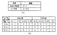
次に、特別図柄の変動内容について、具体例を用いて説明する。
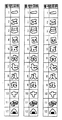
図12は、この実施形態において特別図柄として用いられる左右中図柄の例を示す説明図である。図12に示すように、この実施の形態では、左右中図柄として表示される各図柄は、左右中で同一の12図柄である。図柄番号12の図柄が表示されると、次に、図柄番号1の図柄が表示される。そうして、左右中図柄が、たとえば、「一」、「三」、「五」、「七」、「九」または「下駄」で揃って停止すると確率変動状態となる。すなわちそれらが確変図柄である。
Next, the variation content of the special symbol will be described using a specific example.
FIG. 12 is an explanatory diagram showing an example of left and right middle symbols used as special symbols in this embodiment. As shown in FIG. 12, in this embodiment, the symbols displayed as the left and right middle symbols are the same 12 symbols in the left and right. When the
図13は、可変表示部9に表示される背景画像の例を示す説明図である。この例では、特別図柄が可変表示される際にその背景として表示される背景画像として、道場(図には括弧書きで“部屋の中”と記載)(図13(A))、閃光(図13(B))、オーラ(図13(C))、および煙(図13(D))の背景が用いられる。また、図13(E)に示された表示は、遊技者によって遊技が行なわれていない場合に表示されるデモンストレーション画面(以下、デモ画面という)の一例である。このデモ画面としては、デモ画面A、デモ画面B、デモ画面C、およびデモ画面Dの4種類のうちの何れかを表示可能に構成されている。次に、このデモ画面について説明する。
FIG. 13 is an explanatory diagram illustrating an example of a background image displayed on the
図14および図15は、デモ画面A〜デモ画面Dの具体例を説明するための説明図である。図14(A)にはデモ画面Aの具体例として、道場(部屋の中)を示す画面が示されており、図14(B)には、デモ画面Bの具体例として太陽を表わす画面が示されている。また、図15(C)にはデモ画面Cの具体例として、月を表わす画面が示されており、図15(D)にはデモ画面Dの具体例としてハートを表わす画面が示されている。 14 and 15 are explanatory diagrams for explaining specific examples of the demonstration screen A to the demonstration screen D. FIG. 14A shows a screen showing the dojo (inside the room) as a specific example of the demonstration screen A, and FIG. 14B shows a screen showing the sun as a specific example of the demonstration screen B. It is shown. FIG. 15C shows a screen representing the moon as a specific example of the demonstration screen C, and FIG. 15D shows a screen representing the heart as a specific example of the demonstration screen D. .
これら4種類のデモ画面のうちのいずれが表示されるのかは、可変表示部9に登場するキャラクタの種類によって定められる。このパチンコ遊技機1では、予め定められた複数種類のキャラクタA〜Dのうちのいずれかを遊技場の係員等が任意に設定できるように構成されており、キャラクタAが設定された場合には、そのキャラクタに対応するデモ画面Aが表示される。一方、キャラクタBが設定された場合には、そのキャラクタに対応するデモ画面Bが表示される。同様に、キャラクタCが設定された場合にはそのキャラクタに対応するデモ画面Cが表示され、キャラクタDが設定された場合にはそのキャラクタに対応するデモ画面Dが表示される。これらデモ画面は、遊技者によって遊技が行なわれていない場合に表示されるとともに、遊技場の係員等による操作によってキャラクタが設定された時点においても表示される。これにより遊技場の係員等が設定内容を確認できるように構成されている。
Which of these four types of demonstration screens is displayed is determined by the type of character appearing on the
図16は、可変表示部9に表示されるキャラクタの例を示す説明図である。ここでは、キャラクタA〜キャラクタDのうち、キャラクタAとして分類されるキャラクタA1(図16(A))、キャラクタA2(図16(B))およびキャラクタA3(図16(C))が示されている。これらキャラクタA(A1、A2、A3)は、たとえば、武道大会に登場する格闘系のキャラクタである。このうち、キャラクタA1は、大当り予告用のキャラクタとしても用いられ、キャラクタA1の目が光るように表示されると(予告1)、またはキャラクタA1が吹き出しで予告すると(予告2)、大当り予告が行なわれたことになる。また、キャラクタA1は、リーチを成立させるためのキャラクタとしても用いられ、所定の条件が成立すると、キャラクタAの足が右図柄を蹴るように表示されて左右図柄が同一図柄で停止する表示制御が行なわれる。
FIG. 16 is an explanatory diagram illustrating an example of a character displayed on the
なお、ここでは可変表示部9に表示されるキャラクタとして、格闘系のキャラクタA(A1、A2、A3)のみを示すが、遊技場側で設定を変更することにより、このキャラクタAに代えて、全く系統の異なるキャラクタB(B1、B2、B3)やキャラクタC(C1、C2、C3)、あるいはキャラクタD(D1、D2、D3)を登場させることも可能である。キャラクタB(B1、B2、B3)〜キャラクタD(D1、D2、D3)の図示については省略するが、たとえば、キャラクタBとしては、男性客に好まれがちな格闘系のキャラクタAとは異なる、女性客に好まれがちなキャラクタを採用することが考えられる。なお、キャラクタA以外のキャラクタが設定された場合には、その背景画像もそのキャラクタの特性に応じて変化し、キャラクタAに対応する背景画像(図13(A)〜図13(D)参照))とは異なる背景画像が表示される。
Here, only the fighting characters A (A1, A2, A3) are shown as the characters displayed on the
図17〜図20は、遊技制御基板31から表示制御基板80に送信される表示制御コマンド例を示す説明図である。この例では、1つの表示制御コマンドは2バイト(CMD1,CMD2)で構成される。
17 to 20 are explanatory diagrams illustrating examples of display control commands transmitted from the game control board 31 to the
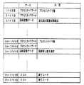
図17は、図柄(特別図柄または普通図柄)の可変表示時間を特定可能な表示制御コマンドと、全図柄(特別図柄または普通図柄)の停止を指示する表示制御コマンドと、大当り状態中の表示制御コマンドとを示す説明図である。 FIG. 17 shows a display control command that can specify the variable display time of a symbol (special symbol or normal symbol), a display control command that instructs to stop all symbols (special symbol or normal symbol), and display control during a big hit state. It is explanatory drawing which shows a command.
図示するように、特別図柄に関する可変表示時間を特定可能な表示コマンドとして、「はずれ(A0)」、「確変時全図柄変動(A2)」、「リーチ短時間(B1)」、「リーチ中期間(B2)」、および「リーチ長期間(B3)」が用意されている。これらの表示制御コマンドA0、A2、B1〜B3は、特別図柄の変動を開始させる際に遊技制御基板31から表示制御基板80に対して出力されるコマンド(特別図柄変動開始コマンド)である。特別図柄の変動を開始させること、およびその可変表示時間、リーチの有無がこれらの特別図柄変動開始コマンドによって表示制御基板80に指令される。また、大当り中の表示状態を指定するためのコマンドとして、「大当り表示」、「V入賞表示」、「10カウント表示」、「ラウンド表示」が用意されている。さらに、普通図柄の変動を開始させるために出力される表示制御コマンドとして、「普通図柄変動中」が用意されている。この「普通図柄変動中」は、普通図柄変動開始コマンドである。全図柄の停止を指示する表示制御コマンドとしては、特別図柄に関しては「全図柄停止」が用意されており、普通図柄に関しては「普通図柄が7で停止」および「普通図柄が0で停止」が用意されている。
As shown in the figure, the display commands that can specify the variable display time for the special symbol are “out of line (A0)”, “total symbol variation during probability variation (A2)”, “reach short time (B1)”, “reach medium period” (B2) "and" Reach long term (B3) "are prepared. These display control commands A0, A2, B1 to B3 are commands (special symbol variation start commands) that are output from the game control board 31 to the
図18には、左図柄の停止図柄を指定する表示制御コマンドが示されている。図18に示すように、2バイトの制御データCMD1,CMD2で構成される表示制御コマンドによって停止させる図柄が指定される。なお、それらの指定において、1バイト目の表示制御データCMD1の値は、「8B(H)」である。 FIG. 18 shows a display control command for designating a stop symbol of the left symbol. As shown in FIG. 18, a symbol to be stopped is designated by a display control command composed of 2-byte control data CMD1 and CMD2. In these designations, the value of the display control data CMD1 in the first byte is “8B (H)”.
図19には、中図柄の停止図柄を指定する表示制御コマンドが示されている。図18に示すように、2バイトの制御データCMD1,CMD2で構成される表示制御コマンドによって停止させる図柄が指定される。なお、それらの指定において、1バイト目の制御データCMD1の値は、「8C(H)」である。 FIG. 19 shows a display control command for designating a stop symbol as a middle symbol. As shown in FIG. 18, a symbol to be stopped is designated by a display control command composed of 2-byte control data CMD1 and CMD2. In these designations, the value of the control data CMD1 in the first byte is “8C (H)”.
図20には、右図柄の停止図柄を指定する表示制御コマンドが示されている。図20に示すように、2バイトの制御データCMD1,CMD2で構成される表示制御コマンドによって停止させる図柄が指定される。なお、それらの指定において、1バイト目の制御データCMD1の値は、「8D(H)」である。 FIG. 20 shows a display control command for designating a stop symbol of the right symbol. As shown in FIG. 20, a symbol to be stopped is designated by a display control command composed of 2-byte control data CMD1 and CMD2. In these designations, the value of the control data CMD1 in the first byte is “8D (H)”.
基本回路53のCPU56は、特別図柄の変動を開始させるときに、図17に示した変動時間を特定可能な特別図柄変動開始コマンドA0,A2,B1,B2,B3のいずれかを表示制御基板80に送出し、続けて、既に決定されている左右中の停止図柄を示す表示制御コマンドを表示制御基板80に送出する。また、図17ではコマンドを明示しなかったが、CPU56は、大当り予告を行なうか否かを示す表示制御コマンドも表示制御基板80に送出する。ただし、大当り予告を行なうか否かを示す情報は、変動時間を特定可能なコマンドに含めてもよい。
When the
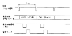
図21は、遊技制御基板31から表示制御基板80に送信される表示制御コマンドを示す説明図である。図21に示すように、表示制御コマンドは表示制御信号CD0〜CD7の8本の信号線で遊技制御基板31から表示制御基板80に送信される。また、遊技制御基板31と表示制御基板80との間には、ストローブ信号を送信するための表示制御信号INTの信号線、表示制御基板80の電源となる+5V,+12Vの供給線、および接地レベルを供給するための信号線も配線されている。
FIG. 21 is an explanatory diagram showing display control commands transmitted from the game control board 31 to the
図22は、遊技制御基板31から表示制御基板80に与えられる表示制御コマンドの送信タイミングの例を示すタイミング図である。この例では、表示制御コマンドを構成する2バイトの表示制御データは、2msごとに送出される。そして、各表示制御データに同期してストローブ信号(表示制御信号INT)が出力される。表示制御用CPU101にはストローブ信号の立上がりで割込がかかり、割込処理プログラムによって各表示制御データが表示制御用CPU101に取込まれる。
FIG. 22 is a timing chart showing an example of the transmission timing of the display control command given from the game control board 31 to the
次に、図23〜図28を参照して、特別図柄の変動パターンの例について説明する。なお、ここでは、キャラクタAが設定されている場合を例とする。 Next, an example of the variation pattern of the special symbol will be described with reference to FIGS. Here, a case where character A is set is taken as an example.
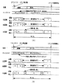
図23は、各変動パターンを構成するパターン(変動状態)を示す説明図である。図24は、リーチとしないはずれ時の図柄の変動の一例を示すタイミング図である。また、図25〜図28は、リーチ時(大当りの場合および大当りとしない場合)の図柄の変動の一例を示すタイミング図である。また、図において、コマンドA0、A2、B1〜B3は、特別図柄の変動を開始させることを指令する「特別図柄変動開始コマンド」である。 FIG. 23 is an explanatory diagram showing patterns (variation states) constituting each variation pattern. FIG. 24 is a timing chart showing an example of a change in symbol when the reach is not reached. FIG. 25 to FIG. 28 are timing charts showing an example of changes in symbols at the time of reach (in the case of big hit and not in big hit). In the figure, commands A0, A2, and B1 to B3 are “special symbol variation start commands” for instructing to start variation of special symbols.
まず、図24(A)に示すように、はずれ時には可変表示部9における「左」の図柄表示エリアにおいて、まず、パターンaに従って図柄の変動が行なわれる。パターンaは、図23に示すように、少しずつ変動速度が上がるパターンである。その後、パターンbの一定速の変動が行なわれ、停止図柄の3図柄前の図柄が表示されるように制御された後、パターンcに従って3図柄の変動が行なわれる。パターンcは、図23に示すように、徐々に遅くなって停止するパターンである。
First, as shown in FIG. 24 (A), in the “left” symbol display area in the
また、可変表示部9における「右」の図柄表示エリアにおいて、パターンaに従って図柄の変動が行なわれる。その後、一定速変動の後、停止図柄の3図柄前の図柄が表示されるように制御された後、パターンcに従って図柄の変動が行なわれる。「中」の図柄表示エリアにおいても、また、パターンaに従って図柄の変動が行なわれる。その後、一定速変動の後、停止図柄の3図柄前の図柄が表示されるように制御された後、パターンcに従って図柄の変動が行なわれる。
Further, in the “right” symbol display area in the
なお、表示制御基板80の表示制御用CPU101は、中図柄が確定するまで、左右図柄を変動方向の正方向と逆方向とに繰返し変動させる。すなわち、左右図柄を、いわゆる揺れ変動状態に表示制御する。揺れ変動とは、図柄が上下に揺れて表示されることをいう。また、揺れ変動は、最終停止図柄(確定図柄)が表示されるまで行なわれる。そして、遊技制御基板31から全図柄停止を指示する表示制御コマンドを受信すると、左右図柄の揺れ変動状態を終了させて左右中図柄が動かない確定状態になる。なお、中図柄も、パターンcによる変動の後に揺れ動作を行ない、その後確定状態になるようにしてもよい。
Note that the
図柄が変動している間、表示制御用CPU101は、背景として「道場」(図13(A)参照)が表示されるように表示制御を行なうとともに、画面上にキャラクタA1(図16参照)を表示して適宜キャラクタA1を運動させるように表示制御を行なう。具体的には、背景およびキャラクタA1をVDP103に通知する。すると、VDP103は、指示された背景の画像データを作成する。また、指示されたキャラクタの画像データを作成し背景画像と合成する。さらに、VDP103は、合成画像に、左右中図柄の画像データを合成する。VDP103は、キャラクタが運動するような表示制御および図柄が変動するような表示制御も行なう。すなわち、予め決められている運動パターンに従ってキャラクタの形状および表示位置を変える。また、表示制御用CPU101から通知される変動速度に応じて図柄表示位置を変えていく。なお、表示制御用CPU101は、左右中の図柄表示エリアにおいて、指定された停止図柄で図柄変動が停止するように、所定のタイミングで停止図柄の3図柄前の図柄を表示制御する。変動開始時に左右中の停止図柄が通知され、かつ、はずれ時の変動パターンは予め決められているので、表示制御用CPU101は、パターンaからパターンbへの切換タイミングおよびパターンbからパターンcへの切換タイミングを認識することができるとともに、差し替えるべき3図柄前の図柄も決定できる。決定された差し替え図柄はVDP103に通知され、VDP103は、そのときに表示している図柄に関係なく、通知された図柄を表示する。
While the symbols are changing, the
図24(B)は、確率変動状態におけるはずれ時の変動パターンの一例を示す。この変動パターンでは、図に示されるように、パターンaおよびパターンbに従って左右中図柄の変動が行なわれた後に、左右中図柄が同時に停止する。 FIG. 24B shows an example of a variation pattern at the time of deviation in the probability variation state. In this variation pattern, as shown in the figure, the left and right middle symbols are simultaneously stopped after the left and right middle symbols are varied according to the pattern a and the pattern b.
図25は、遊技制御基板31からの特別図柄変動開始コマンドによって変動時間19.5秒(リーチ短期間)が通知されたときに表示される変動パターンの例を示す。図25には、複数の変動パターンとして(A)〜(C)の3パターンが例示されている。表示制御用CPU101は、リーチ短期間が通知されると、19.5秒の複数の変動パターンのうちのいずれの変動パターンを用いるのかを独自に決定する。
FIG. 25 shows an example of a variation pattern displayed when a variation time of 19.5 seconds (reach short period) is notified by a special symbol variation start command from the game control board 31. FIG. 25 illustrates three patterns (A) to (C) as a plurality of variation patterns. When notified of the reach short period, the
図25(A)に示された変動パターンでは、左右中図柄が停止した後パターンdの中図柄の変動が行なわれる。パターンdは、変動速度が徐々に低下し、その後一定速度で変動が行なわれるパターンである。そして、リーチ動作に入り、パターンbおよびパターンcに従って中図柄の変動が行なわれる。遊技制御基板31から全図柄停止を指示する表示制御コマンドを受信すると、左右図柄の揺れ変動状態を終了させて左右中図柄が動かない確定状態になる。また、表示制御用CPU101は、遊技制御基板31から通知されている停止図柄で図柄が確定するように、リーチ動作開始前に図柄の差し替え(図柄の飛ばし制御)を行なう。変動パターンは予め決められているので、表示制御用CPU101は、パターンdからパターンbへの切換タイミングおよびパターンbからパターンcへの切換タイミングを認識することができるとともに、差し替えるべき3図柄前の図柄も決定できる。なお、中図柄の変動中に、背景およびキャラクタの種類は変化しない。
In the variation pattern shown in FIG. 25A, the middle symbol of the pattern d is varied after the left and right middle symbols are stopped. The pattern d is a pattern in which the fluctuation speed is gradually decreased and thereafter the fluctuation is performed at a constant speed. Then, the reach operation is started, and the middle symbols are changed according to the patterns b and c. When the display control command for instructing the stop of all symbols is received from the game control board 31, the left and right symbols are fluctuated and the fixed state in which the right and left middle symbols do not move is reached. Further, the
図25(B)に示された変動パターンでは、左右図柄が停止した後パターンdの中図柄の変動が行なわれる。そして、リーチ動作に入り、パターンaおよびパターンcに従って中図柄の変動が行なわれる。遊技制御基板31から全図柄停止を指示する表示制御コマンドを受信すると、左右図柄の揺れ変動状態を終了させて左右中図柄が動かない確定状態になる。また、表示制御用CPU101は、遊技制御基板31から通知されている停止図柄で図柄が確定するように、リーチ動作開始前に図柄の差し替えを行なう。なお、図25(B)に示された変動パターンでは右図柄停止時に、表示制御用CPU101は、キャラクタA1が右図柄を蹴るように表示制御を行なう(図16(A)参照)。したがって、遊技者は、あたかも、キャラクタA1が右図柄を蹴ることによってリーチが成立したように感ずる。
In the variation pattern shown in FIG. 25B, the middle symbol of the pattern d is varied after the left and right symbols are stopped. Then, the reach operation is started, and the middle symbols are changed according to the patterns a and c. When the display control command for instructing the stop of all symbols is received from the game control board 31, the left and right symbols are fluctuated and the fixed state in which the right and left middle symbols do not move is reached. Further, the
図25(C)に示された変動パターンでは、左右図柄が停止した後パターンdの中図柄の変動が行なわれる。そして、リーチ動作に入り、パターンbおよびパターンhに従って中図柄の変動が行なわれる。パターンhは、一時停止の後に、0.9図柄逆変動して0.9図柄順変動するパターンである。遊技制御基板31から全図柄停止を指示する表示制御コマンドを受信すると、左右図柄の揺れ変動状態を終了させて左右中図柄が動かない確定状態になる。また、表示制御用CPU101は、遊技制御基板31から通知されている停止図柄で図柄が確定するように、リーチ動作開始前に図柄の差し替えを行なう。なお、図25(C)に示された変動パターンでは、右図柄が停止すると、表示制御用CPU101は、背景画像を「オーラ」(図13(C)参照)に切換えるとともに、画面に現われるキャラクタをキャラクタA2(図16(B)参照)に切換える。
In the variation pattern shown in FIG. 25C, the middle symbol of the pattern d is varied after the left and right symbols are stopped. Then, the reach operation is started, and the middle symbols are changed according to the patterns b and h. The pattern h is a pattern in which 0.9 symbols reversely change and 0.9 symbols change in order after the temporary stop. When the display control command for instructing the stop of all symbols is received from the game control board 31, the left and right symbols are fluctuated and the fixed state in which the right and left middle symbols do not move is reached. Further, the
図25(A)〜(C)に示された変動時間19.5秒の変動パターンでも、表示制御用CPU101は、中図柄が確定するまで、左右図柄を上下に揺れ動作させる。また、中図柄の図柄差し替え制御は、右図柄が停止するタイミングで実行される。表示制御用CPU101は、変動開始時に遊技制御基板31から通知されている中停止図柄と、リーチ変動時間(たとえば図25(A)におけるパターンa、パターンbおよびパターンcの変動時間)における図柄の変動数とに応じて、差し替え図柄を決定する。
Even in the variation pattern with the variation time of 19.5 seconds shown in FIGS. 25A to 25C, the
図26は、遊技制御基板31からの特別図柄変動開始コマンドによって変動時間24.5秒(リーチ中期間)が通知されたときに表示される変動パターンの例を示す。図26には、複数の変動パターンとして(A)〜(C)の3パターンが例示されている。表示制御用CPU101は、変動時間として24.5秒が通知されると、複数の変動パターンのうちのいずれの変動パターンを用いるのかを独自に決定する。
FIG. 26 shows an example of a variation pattern that is displayed when a variation time of 24.5 seconds (during reach) is notified by a special symbol variation start command from the game control board 31. FIG. 26 illustrates three patterns (A) to (C) as a plurality of variation patterns. When the
図26(A)に示された変動パターンでは、左右図柄が停止した後パターンdの中図柄の変動が行なわれる。そして、リーチ動作に入り、パターンbおよびパターンfに従って中図柄の変動が行なわれる。パターンfは高速変動であり、パターンfによる変動開始後に一時停止期間がおかれる。遊技制御基板31から全図柄停止を指示する制御制御コマンドを受信すると、左右図柄の揺れ変動状態を終了させて左右中図柄が動かない確定状態になる。また、表示制御用CPU101は、遊技制御基板31から通知されている停止図柄で図柄が確定するように、リーチ動作開始前に図柄の差し替えを行なう。なお、図26(A)に示された変動パターンでは、右図柄が停止すると、表示制御用CPU101は、背景画像を「閃光」(図13(B)参照)に切換える。また、右図柄停止時に、表示制御用CPU101を、キャラクタA1が右図柄を蹴るように表示制御を行なう(図16(A)参照)。さらに、表示制御用CPU101は、大当り予告を行なうことが決定されている場合には、左右図柄変動期間において、キャラクタA1の目が光るような表示制御またはキャラクタが発生するような表示制御を行なう。
In the variation pattern shown in FIG. 26A, the middle symbol of the pattern d is varied after the left and right symbols are stopped. Then, the reach operation is started, and the middle symbols are changed according to the patterns b and f. The pattern f is a high-speed fluctuation, and a temporary stop period is set after the fluctuation start by the pattern f. When a control control command for instructing the stop of all symbols is received from the game control board 31, the left / right symbol fluctuation state is terminated and a fixed state in which the left / right middle symbols do not move is established. Further, the
図26(B)に示された変動パターンでは、左右図柄が停止した後パターンdの中図柄の変動が行なわれる。そして、リーチ動作に入り、パターンbおよびパターンhに従って中図柄の変動が行なわれる。遊技制御基板31から全図柄停止を指示する表示制御コマンドを受信すると、左右図柄の揺れ変動状態を終了させて左右中図柄が動かない確定状態になる。また、表示制御用CPU101は、遊技制御基板31から通知されている停止図柄で図柄が確定するように、リーチ動作開始前に図柄の差し替えを行なう。図26(B)に示された変動パターンでは、右図柄が停止すると、表示制御用CPU101は、背景画像を「閃光」(図13(B)参照)に切換える。また、表示制御用CPU101は、大当り予告を行なうことが決定されている場合には、左右図柄変動期間において、キャラクタA1の目が光るような表示制御またはキャラクタが発生するような表示制御を行なう。
In the variation pattern shown in FIG. 26B, the middle symbol of the pattern d is varied after the left and right symbols are stopped. Then, the reach operation is started, and the middle symbols are changed according to the patterns b and h. When the display control command for instructing the stop of all symbols is received from the game control board 31, the left and right symbols are fluctuated and the fixed state in which the right and left middle symbols do not move is reached. Further, the
図26(C)に示された変動パターンでは、左右図柄が停止した後パターンdの中図柄の変動が行なわれる。そして、リーチ動作に入り、パターンbおよびパターンcに従って中図柄の変動が行なわれる。遊技制御基板31から全図柄停止を指示する表示制御コマンドを受信すると、左右図柄の揺れ変動状態を終了させて左右中図柄が動かない確定状態になる。また、表示制御用CPU101は、遊技制御基板31から通知されている停止図柄で図柄が確定するように、リーチ動作開始前に図柄の差し替え(図柄の飛ばし制御)を行なう。図26(C)に示された変動パターンでは、右図柄が停止すると、表示制御用CPU101は、背景画像を「オーラ」(図13(C)参照)に切換えるとともに、画面に現われるキャラクタをキャラクタA2(図16(C)参照)に切換える。また、表示制御用CPU101は、大当り予告を行なうことが決定されている場合には、左右図柄変動期間において、キャラクタAの目が光るような表示制御またはキャラクタが発生するような表示制御を行なう。
In the variation pattern shown in FIG. 26C, the middle symbol of pattern d is varied after the left and right symbols have stopped. Then, the reach operation is started, and the middle symbols are changed according to the patterns b and c. When the display control command for instructing the stop of all symbols is received from the game control board 31, the left and right symbols are fluctuated and the fixed state in which the right and left middle symbols do not move is reached. Further, the
図26(A)〜(C)に示された変動時間24.5秒の変動パターンでも、表示制御用CPU101は、中図柄が確定するまで、左右図柄を上下に揺れ動作させる。また、中図柄の図柄飛ばし制御は、右図柄が停止するタイミングで実行される。
Even in the variation pattern of variation time 24.5 seconds shown in FIGS. 26A to 26C, the
図27および図28は、遊技制御基板31からの特別図柄変動開始コマンドによって変動時間29.5秒(リーチ長期間)が通知されたときに表示される変動パターンの例を示す。図27および図28には、複数の変動パターンとして3パターンが例示されている。表示制御用CPU101は、変動時間として29.5秒が通知されると、複数の変動パターンのうちのいずれの変動パターンを用いるのかを独自に決定する。なお、(C1)および(C2)の変動パターンは1つの変動パターンの異なる局面を示す例である。よって、以下、図28(C1)および(C2)に例示された変動パターンを図28(C)に示された変動パターンと呼ぶことがある。
27 and 28 show examples of variation patterns displayed when a variation time of 29.5 seconds (reach long-term) is notified by a special symbol variation start command from the game control board 31. FIG. 27 and 28 illustrate three patterns as a plurality of variation patterns. When 29.5 seconds is notified as the variation time, the
図27(A)に示された変動パターンでは、左右図柄が停止した後パターンdの中図柄の変動が行なわれる。そして、リーチ動作に入り、パターンbによる変動後、一時停止期間をおいてパターンfに従って中図柄の変動が行なわれる。また、表示制御用CPU101は、遊技制御基板31から通知されている停止図柄で図柄が確定するように、リーチ動作開始前に図柄の差し替えを行なう。なお、図27(A)に示された変動パターンでは、右図柄が停止すると、表示制御用CPU101は、背景画像を「閃光」(図13(B)参照)に切換える。また、表示制御用CPU101は、大当り予告を行なうことが決定されている場合には、左右図柄変動期間において、キャラクタA1の目が光るような表示制御またはキャラクタが発生するような表示制御を行なう。
In the variation pattern shown in FIG. 27A, the middle symbol of the pattern d is varied after the left and right symbols are stopped. Then, the reach operation is started, and after the fluctuation due to the pattern b, the middle symbol is changed according to the pattern f after a temporary stop period. Further, the
さらに、図27(A)に示された変動パターンでは、中図柄がパターンfで高速変動する際に、左右図柄も同様に高速変動する。したがって、最終停止図柄が大当り図柄の組合せである場合には、一時停止時の一時停止図柄も、図柄の種類は異なるが、やはり大当り図柄の組合せである。よって、遊技者は、一時停止時に大当りが発生したと感ずるとともに、再変動後に再度大当り図柄が提供されて再度興趣がかき立てられる。なお、一時停止図柄は表示制御用CPU101が、停止図柄から逆算して独自に決定した図柄である。パターンfの変動速度と変動時間とは予め決められているので、表示制御用CPU101は、最終停止図柄から一時停止図柄を容易に逆算することができる。
Further, in the variation pattern shown in FIG. 27A, when the middle symbol changes at high speed with the pattern f, the left and right symbols also change at high speed in the same manner. Therefore, when the final stop symbol is a combination of jackpot symbols, the temporary stop symbol at the time of pause is also a combination of jackpot symbols, although the types of symbols are different. Therefore, the player feels that a big hit has occurred at the time of the suspension, and is provided with the big hit symbol again after re-variation, and is intrigued again. The temporary stop symbol is a symbol uniquely determined by the
図27(B)に示された変動パターンでは、左右図柄が停止した後パターンdの中図柄の変動が行なわれる。そして、リーチ動作に入り、パターンbおよびパターンhによる変動後、一時停止期間をおいてパターンfに従って中図柄の変動が行なわれる。また、表示制御用CPU101は、遊技制御基板31から通知されている停止図柄で図柄が確定するように、リーチ動作開始前に図柄の差し替えを行なう。なお、図27(B)に示された変動パターンでは、右図柄が停止すると、表示制御用CPU101は、背景画像を「オーラ」(図13(C)参照)に切換えるとともに、画面に現われるキャラクタをキャラクタA2(図16参照)に切換える。また、表示制御用CPU101は、大当り予告を行なうことが決定されている場合には、左右図柄変動期間において、キャラクタA1の目が光るような表示制御またはキャラクタが発生するような表示制御を行なう。
In the variation pattern shown in FIG. 27B, the middle symbol of the pattern d is varied after the left and right symbols are stopped. Then, the reach operation is started, and after the fluctuation due to the pattern b and the pattern h, the middle symbol is changed according to the pattern f after a temporary stop period. Further, the
図28(C)に示された変動パターンでは、左右図柄が停止した後、パターンcに従って中図柄の変動が行なわれる。その後、パターンgに従って中図柄の変動が行なわれる。パターンgはコマ送りのパターンである。また、表示制御用CPU101は、遊技制御基板31から通知されている停止図柄で図柄が確定するように、リーチ動作開始前に図柄の差し替えを行なう。なお、図28(C)に示された変動パターンでは、右図柄が停止すると、表示制御用CPU101は、背景画像を「煙」(図13(D)参照)に切換えるとともに、画面に現われるキャラクタをキャラクタA3(図16参照)に切換える。また、表示制御用CPU101は、大当り予告を行なうことが決定されている場合には、左右図柄変動期間において、キャラクタA1の目が光るような表示制御またはキャラクタが発生するような表示制御を行なう。
In the variation pattern shown in FIG. 28C, after the left and right symbols are stopped, the middle symbol is varied according to the pattern c. Thereafter, the middle symbols are changed according to the pattern g. Pattern g is a frame advance pattern. Further, the
図27および図28に示された変動時間29.5秒の変動パターンでも、表示制御用CPU101は、中図柄が確定するまで、左右図柄を上下に揺れ動作させる。また、中図柄の図柄飛ばし制御は、右図柄が停止するタイミングで実行される。
Even in the variation pattern with the variation time of 29.5 seconds shown in FIGS. 27 and 28, the
図28(C)に示されたコマ送りを含む変動パターンでは、リーチ動作開始時に、大当りとするか否かにかかわらず、左右中の表示図柄を揃ったものとする。すると、左右中図柄の停止図柄は変動開始時に遊技制御基板31から表示制御基板80に送信されているので、停止図柄とリーチ動作開始時の図柄(左右中が揃ったもの)とから、コマ送り時のコマ数は決まる。
In the variation pattern including the frame advance shown in FIG. 28C, it is assumed that the left and right display symbols are aligned at the start of the reach operation regardless of whether or not the big hit is made. Then, since the stop symbols of the left and right middle symbols are transmitted from the game control board 31 to the
たとえば、図28(C1)に示された例では、確定図柄が「七」(左図柄)、「五」(中図柄)、「七」(右図柄)であった場合の例である。リーチ動作開始時の図柄は「七」、「七」、「七」であるから、コマ送り時には10図柄の変動がなされる必要がある。また、図28(C2)に示された例では、確定図柄が「七」(左図柄)、「二」(中図柄)、「七」(右図柄)であった場合の例である。リーチ動作開始時の図柄は「七」、「七」、「七」であるから、コマ送り時には7図柄の変動がなされる必要がある。 For example, in the example shown in FIG. 28 (C1), the confirmed symbols are “seven” (left symbol), “five” (middle symbol), and “seven” (right symbol). Since the symbols at the start of the reach operation are “seven”, “seven” and “seven”, it is necessary to change 10 symbols at the time of frame advance. The example shown in FIG. 28C2 is an example in which the confirmed symbols are “seven” (left symbol), “two” (middle symbol), and “seven” (right symbol). Since the symbols at the start of the reach operation are “seven”, “seven”, and “seven”, it is necessary to change seven symbols at the time of frame advance.
すると、コマ送りの時間を常に一定としておくと、変動時間が29.5秒からずれてしまう。ずらさないようにするためには、送りコマ数に応じてコマ送りの変動速度を変えなければならない。そのような表示制御を行なうのは不自然である。つまり、遊技者に不信感を与える。そこで、表示制御用CPU101は、図28(C)に示された変動パターンを用いることに決定した場合には、コマ送り変動時の変動速度が常に一定となるようにリーチ動作開始時のタイミングを調整する。
Then, if the frame advance time is always constant, the fluctuation time will deviate from 29.5 seconds. In order to avoid shifting, it is necessary to change the frame feed fluctuation speed in accordance with the number of frames to be fed. It is unnatural to perform such display control. That is, it gives distrust to the player. Therefore, if the
つまり、送りコマ数が少ないときにはリーチ動作開始のタイミングを遅らせ、送りコマ数が多いときにはリーチ動作開始のタイミングを相対的に早める。そのような表示制御を行なえば、全体の変動時間が29.5秒に保たれた上で、コマ送り変動時の変動速度を常に一定にすることができる。 That is, when the number of frames to be sent is small, the timing for starting the reach operation is delayed, and when the number of frames to be sent is large, the timing for starting the reach operation is relatively advanced. If such display control is performed, the fluctuation speed at the time of fluctuating frame feed can be made constant at all times while keeping the whole fluctuation time at 29.5 seconds.
以下、上述した表示例を実現するための遊技制御基板31および表示制御基板80における制御について説明する。
Hereinafter, control in the game control board 31 and the
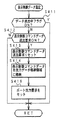
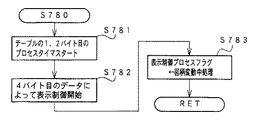
図29は、図11に示された特別図柄プロセス処理におけるコマンド送信完了待ち処理(S303)を示すフローチャートである。S302の停止図柄設定処理において変動時間と停止図柄とが決定されると、それらを指示するための表示制御コマンドの送出制御が行なわれるのであるが、まず、表示制御コマンドの送出が完了したか否かが判断される(S303a)。CPU56は、特別図柄の変動を開始させる際に、特別図柄変動開始コマンドと左右中の停止図柄を示す表示制御コマンドと大当り予告を行なうか否かを示す表示制御コマンドとを表示制御基板80に送出する。このS303aでは、それらのすべてのコマンドの送出が完了したか否かが確認される。
FIG. 29 is a flowchart showing command transmission completion waiting processing (S303) in the special symbol process shown in FIG. When the variation time and the stop symbol are determined in the stop symbol setting process of S302, the transmission control of the display control command for instructing them is performed. First, whether or not the transmission of the display control command is completed. Is determined (S303a). When starting the change of the special symbol, the
表示制御コマンドの送出が完了している場合には、表示制御基板80に通知した変動時間を遊技制御基板31側においても測定するための変動時間タイマがスタートされる(S303b)。次に、特別図柄プロセスフラグの値が、全図柄停止待ち処理に移行できる値に更新され(S303c)、処理が終了する。
図30は、図11に示された特別図柄プロセス処理における全図柄停止待ち処理(S304)を示すフローチャートである。S304では、まず、変動時間タイマがタイムアップしたか否かが確認される(S304a)。タイムアップしている場合には、全図柄停止を指示する表示制御コマンドが設定される(S304b)。次に、表示制御コマンドデータ送出要求がセットされ(S304c)。次に、特別図柄プロセスフラグの値が、大当り表示処理に移行できる値に更新され(S304d)、処理が終了する。なお、表示制御コマンドデータ送出要求は、表示制御データ設定処理(S5)で参照される。
When the transmission of the display control command is completed, a variable time timer for measuring the variable time notified to the
FIG. 30 is a flowchart showing the all symbol stop waiting process (S304) in the special symbol process shown in FIG. In S304, first, it is confirmed whether or not the variable time timer has expired (S304a). If the time is up, a display control command for instructing all symbols to stop is set (S304b). Next, a display control command data transmission request is set (S304c). Next, the value of the special symbol process flag is updated to a value that can shift to the jackpot display process (S304d), and the process ends. The display control command data transmission request is referred to in the display control data setting process (S5).
以上のように、特別図柄プロセス処理において、CPU56は、特別図柄の変動を開始させる際にその変動時間を特定可能な情報や停止図柄を指示する情報等を表示制御基板80に送出し、変動時間タイマがタイムアップしたら、すなわち指示した変動時間が終了したら、全図柄停止を指示する情報を表示制御基板80に送出する。その間、CPU56は、表示制御基板80に表示制御コマンドを送出しない。したがって、遊技制御基板31のCPU56の表示制御に要する負荷は大きく低減されている。
As described above, in the special symbol process, the
図31は、表示制御データ設定処理(図8に示されたメイン処理におけるS5)を示すフローチャートである。表示制御データ設定処理において、まず、データ送信中フラグがセットされているか否かが確認される(S411)。セットされていなければ、表示制御コマンドデータの送出要求フラグがセットされているか否かが確認される(S412)。送出要求フラグがセットされていれば、送出要求フラグがリセットされる(S413)。また、送出すべき表示制御コマンドデータが出力データ格納領域に設定されるとともに(S414)、ポート出力要求がセットされる(S416)。なお、表示制御コマンドデータの送出要求フラグは、特別図柄プロセス処理においてセットされる。また、データ送出中フラグは、後述する表示制御データ出力処理においてセットされる。 FIG. 31 is a flowchart showing the display control data setting process (S5 in the main process shown in FIG. 8). In the display control data setting process, first, it is confirmed whether or not the data transmission flag is set (S411). If it is not set, it is checked whether or not the display control command data transmission request flag is set (S412). If the transmission request flag is set, the transmission request flag is reset (S413). Further, display control command data to be sent is set in the output data storage area (S414), and a port output request is set (S416). The display control command data transmission request flag is set in the special symbol process. The data sending flag is set in the display control data output process described later.
図32は、図8に示されたメイン処理における表示制御データ出力処理(S6)を示すフローチャートである。表示制御データ出力処理において、まず、ポート出力要求がセットされているか否かが判定される(S421)。ポート出力要求がセットされていると判定された場合には、ポート出力要求がリセットされ(S422)、ポート格納領域の内容(表示制御コマンドの1バイト目)が出力ポート571に出力される(S423)。次に、ポート出力カウンタが+1される(S424)。次に、INT信号がローレベル(オン状態)とされ(S425)、データ送出中フラグがオンとされる(S426)。 FIG. 32 is a flowchart showing the display control data output process (S6) in the main process shown in FIG. In the display control data output process, first, it is determined whether or not a port output request is set (S421). If it is determined that the port output request is set, the port output request is reset (S422), and the contents of the port storage area (the first byte of the display control command) are output to the output port 571 (S423). ). Next, the port output counter is incremented by 1 (S424). Next, the INT signal is set to the low level (ON state) (S425), and the data sending flag is turned ON (S426).
ポート出力要求がセットされていない場合には、ポート出力カウンタの値が0であるか否かが判定される(S431)。ポート出力カウンタの値が0でない場合には、ポート出力カウンタの値が1であるか否かが確認される(S432)。ポート出力カウンタの値が1である場合には、表示制御コマンドの1バイト目に関するINT信号オフタイミングになっているため、INT信号がオフ状態(=1)とされる(S433)。また、ポート出力カウンタの値が+1される(S434)。 If the port output request is not set, it is determined whether or not the value of the port output counter is 0 (S431). If the value of the port output counter is not 0, it is confirmed whether or not the value of the port output counter is 1 (S432). If the value of the port output counter is 1, the INT signal is turned off for the first byte of the display control command, so the INT signal is turned off (= 1) (S433). Further, the value of the port output counter is incremented by 1 (S434).
ポート出力カウンタの値が2である場合には(S435)、表示制御コマンドの2バイト目が出力タイミングになっているので、ポート格納領域の内容(表示制御コマンドの2バイト目)が出力ポート571に出力される(S436)。次に、ポート出力カウンタが+1される(S437)。次に、INT信号がローレベルとされる(S438)。 When the value of the port output counter is 2 (S435), since the second byte of the display control command is the output timing, the contents of the port storage area (second byte of the display control command) are output port 571. (S436). Next, the port output counter is incremented by 1 (S437). Next, the INT signal is set to a low level (S438).
ポート出力カウンタの値が2でない場合には、すなわち3である場合には、表示制御コマンドの2バイト目に関するINT信号オブタイミングになっているので、ポート出力カウンタの値がクリアされるとともに(S441)、INT信号がオフ(ハイレベル状態)とされる(S442)。次に、データ送信中フラグがオフとされる(S443)。 When the value of the port output counter is not 2, that is, when it is 3, since it is the INT signal of timing related to the second byte of the display control command, the value of the port output counter is cleared (S441). ), The INT signal is turned off (high level state) (S442). Next, the data transmission flag is turned off (S443).
この実施の形態では、表示データ出力処理は2msに1回実行される。したがって、表示データ出力処理によって、図22に示されたように、2msごとに1バイトのデータが出力される。 In this embodiment, the display data output process is executed once every 2 ms. Therefore, by the display data output process, as shown in FIG. 22, 1-byte data is output every 2 ms.
図33は、大入賞口開放開始処理(図11のS306参照)を示すフローチャートである。大入賞口開放開始処理においては、まず、開放時間カウンタが+1される(S501)。開放時間カウンタは、可変入賞球装置19の継続開放時間(=30秒)を計時するためのカウンタである。次に、開放時間カウンタのカウント値が所定値(=30秒)に達しているか否かが判断される(S502)。所定値に達している場合には、大入賞口を閉成させるために後述するS508に処理が移行するが、所定値に達していない場合にはカウントスイッチ23による10カウントの検出があったか否かが判断される(S503)。10カウントの検出がないと判断された場合には、Vカウントスイッチ22によってV入賞が検出されたか否かが判断され(S514)、V入賞も検出されていない場合には、処理が終了する。一方、V入賞が検出されている場合には、V入賞の検出を示すV検出フラグがセットされ(S515)、その後、V入賞表示を行なうためのV表示要求フラグがセットされ(S516)、S504に移行する。
FIG. 33 is a flowchart showing a special winning opening opening process (see S306 in FIG. 11). In the big prize opening opening process, first, the opening time counter is incremented by 1 (S501). The opening time counter is a counter for measuring the continuous opening time (= 30 seconds) of the variable winning
S503でカウントスイッチ23による10カウントの検出出力があったと判断された場合、もしくはS516の処理の後、10カウントカウンタのカウント値が+1される(S504)。次に、10カウント表示を行なうための10カウント表示更新要求フラグがセットされる(S505)。
When it is determined in S503 that there is a 10 count detection output from the
次に、10カウントカウンタのカウント値が10以上であるか否かが判断される(S506)。10カウントカウンタのカウント値が10に達していないと判断された場合には(S506でNO)、ソレノイド21の励磁が継続される(S518)。一方、10カウントカウンタのカウント値が11に達している場合にはS506でYESの判断がなされ、10カウントカウンタのカウント値がリセットされる(S507)。その後、ソレノイド21の励磁が解除され(S508)、これにより大入賞口が閉成される。
Next, it is determined whether or not the count value of the 10 count counter is 10 or more (S506). When it is determined that the count value of the 10-count counter has not reached 10 (NO in S506), excitation of the
次に、V検出フラグが設定されているか否かが判断される(S509)。V検出フラグが設定されている場合にはV入賞が発生しているため、現在のラウンドが最終ラウンド(16ラウンド目)であるか否かが判断され(S510)、最終ラウンドでない場合にはラウンドカウンタのカウント値が+1される(S511)。その後、特別図柄プロセスフラグの値が大入賞口開放中処理に移行するための値に更新される(S512)。続いて、V検出フラグがリセットされ(S513)、処理が終了する。 Next, it is determined whether or not the V detection flag is set (S509). When the V detection flag is set, V winning has occurred, so it is determined whether or not the current round is the final round (the 16th round) (S510). The count value of the counter is incremented by 1 (S511). Thereafter, the value of the special symbol process flag is updated to a value for shifting to the special winning opening opening process (S512). Subsequently, the V detection flag is reset (S513), and the process ends.
S509でV検出フラグが設定されていないと判断された場合もしくはS510で最終ラウンドに達していると判断された場合には、特別図柄プロセスフラグの値が大当り終了処理に移行するための値に更新され(S517)、V検出フラグがリセットされた後に(S513)、処理が終了する。 If it is determined in S509 that the V detection flag is not set or if it is determined in S510 that the final round has been reached, the value of the special symbol process flag is updated to a value for shifting to the jackpot end process. (S517), after the V detection flag is reset (S513), the process ends.
次に、表示制御用CPU101の動作を説明する。
図34は、表示制御用CPU101のメイン処理を示すフローチャートである。パチンコ遊技機1の電源が投入されると、図21に示したように遊技制御基板31から+5V,+12Vの供給線を通じて表示制御基板80に電源が供給される。このメイン処理においては、その電源の供給に伴ってRAM101aやI/Oポート、VDP103などをイニシャライズする処理が実行される(S701)。次に、表示画面設定タイマおよび基準タイマの計時が開始される(S702)。表示画面設定タイマは、パチンコ遊技機1の電源の投入時から経過した時間を計時するタイマである。一方、基準タイマは、画像を表示するキャラクタの種類を設定可能な単位時間(5分)を計時するタイマである。次に、可変表示装置8にキャラクタの設定が可能である旨の表示がなされる(S703)。その表示例を図51に示す。なお、図51(C)は、一旦、何らかの設定がなされた後に、再度設定をやり直すことが可能であることを報知する表示である。たとえば、S703においては、図51(D)の表示がなされる。これにより、電源を投入した遊技場の係員等は、キャラクタの設定が可能な設定可能状態となったことを把握できる。特に、S703において図51(D)が表示されるのは、設定操作をしないで所定時間放置すると図51(D)の背景画面に対応するキャラクタDが自動的に設定されるように構成されているため、その旨を遊技場の係員等に報知するためである。
Next, the operation of the
FIG. 34 is a flowchart showing main processing of the
次に、表示用乱数(図35参照)を更新する処理が繰返し実行される(S704)。
図35は、表示制御用CPU101が扱う表示用乱数を示す説明図である。図35(A)に示すように、表示用乱数として、大当り予告用乱数とリーチ用乱数とが準備されている。大当り予告用乱数は大当り予告の内容(予告1または予告2)を決定するためのものであり、リーチ用乱数は、変動パターンを決定するためのものである。また、図35(B)には、リーチ用乱数の値と変動パターンとの関係が示されている。
Next, the process of updating the display random number (see FIG. 35) is repeatedly executed (S704).
FIG. 35 is an explanatory diagram showing display random numbers handled by the
図35(B)において、A,B,Cは、図25〜図28における(A),(B),(C)に対応している。すなわち、抽出されたリーチ用乱数の値が上段に示される値であれば、下段に示された変動パターンで図柄の変動が行なわれる。たとえば、遊技制御基板31から変動時間として29.5秒(リーチ長期間)が通知され、抽出したリーチ用乱数の値が21であり、大当りとする場合には、図28(C)に示された変動パターンで変動を行なうことが決定される。なお、大当りとするか否かは、変動時間を指定する表示制御コマンドとともに送出された左右中図柄の停止図柄を示す表示制御コマンドに基づいて判定される。 In FIG. 35B, A, B, and C correspond to (A), (B), and (C) in FIGS. That is, if the value of the extracted reach random number is the value shown in the upper stage, the symbols are changed in the change pattern shown in the lower stage. For example, when 29.5 seconds (reach long-term) is notified as a variation time from the game control board 31 and the extracted random number for reach is 21, which is a big hit, it is shown in FIG. It is determined that the variation is performed with the variation pattern. Whether or not to win is determined based on a display control command indicating a stop symbol of the middle left and right symbols sent together with a display control command designating a variation time.
この実施の形態では、実際の変動制御などは、タイマ割込処理によって行なわれる。タイマ割込は、たとえば2msごとに発生する。図36に示すように、タイマ割込処理では、表示制御用CPU101によって表示制御プロセス処理(S711)が実行される。表示制御プロセス処理では、表示制御プロセスフラグの値に応じた表示制御が行なわれる。
In this embodiment, actual variation control and the like are performed by timer interrupt processing. A timer interrupt occurs every 2 ms, for example. As shown in FIG. 36, in the timer interrupt process, the display control process (S711) is executed by the
図37は、表示制御用CPU101のIRQ2割込処理を示すフローチャートである。遊技制御基板31からの表示制御コマンドは、このIRQ2割込によって表示制御用CPU101に受信される。IRQ2割込処理において、まず、データ受信中フラグがセットされているか否かが確認される(S601)。セットされていない場合には、この割込は表示制御コマンドデータにおける第1バイトの表示制御データ送出による割込であると判断できる。そこで、この場合にはポインタがクリアされるとともに(S602)、データ受信中フラグがセットされる(S603)。その後、S604に移行する。ポインタは、表示制御用CPU101のRAMの表示制御コマンドデータ格納エリアにおける何バイト目に受信データを格納するか指し示すものである。
FIG. 37 is a flowchart showing the IRQ2 interrupt process of the
データ受信中フラグがセットされている場合には、ストローブ信号のオフを条件として(S604)、入力ポートからデータが入力され、表示制御コマンドデータ格納エリアにおいてポインタによって示されているアドレスにその入力データが格納される(S605)。次に、ポインタの値が+1される(S606)。 If the data receiving flag is set, data is input from the input port on condition that the strobe signal is turned off (S604), and the input data is stored at the address indicated by the pointer in the display control command data storage area. Is stored (S605). Next, the value of the pointer is incremented by 1 (S606).
次に、ポインタの値が2であるか否かが判断され(S607)、2でない場合には処理が終了するが、2の場合にも2バイトで構成される表示制御コマンドデータの受信が完了したことになるため、データ受信完了フラグがセットされた後(S608)、データ受信中フラグがリセットされる(S609)。以上のような処理によって、表示制御データCMD1,CMD2が表示制御基板80において受信される。
Next, it is determined whether or not the value of the pointer is 2 (S607). If it is not 2, the process ends, but in the case of 2, reception of display control command data composed of 2 bytes is also completed. Thus, after the data reception completion flag is set (S608), the data reception flag is reset (S609). The display control data CMD1 and CMD2 are received by the
図38は、図36に示されたタイマ割込処理における表示制御プロセス処理(S711)を示すフローチャートである。表示制御プロセス処理では、表示制御プロセスフラグの値に応じてステップS720〜S870のうちのいずれかの処理が行なわれる。各処理において、以下の処理が実行される。 FIG. 38 is a flowchart showing the display control process (S711) in the timer interrupt process shown in FIG. In the display control process, one of steps S720 to S870 is performed according to the value of the display control process flag. In each process, the following process is executed.
表示制御コマンド受信待ち処理(S720):IRQ2割込処理によって、変動時間を特定可能な表示制御コマンドを受信したか否か確認する。 Display control command reception waiting process (S720): It is confirmed whether or not a display control command capable of specifying the variation time is received by the IRQ2 interrupt process.
リーチ動作設定処理(S750):リーチ時には、図25〜図28に示された変動パターンのうちのいずれのパターンを使用するのかを決定するとともに、大当り予告の種類を決定する。 Reach operation setting process (S750): At the time of reach, it is determined which of the variation patterns shown in FIGS. 25 to 28 is used and the type of jackpot notice is determined.
全図柄変動開始処理(S780):左右中図柄の変動が開始されるように制御する。
図柄変動中処理(S810):変動パターンを構成する各変動状態(変動速度や背景、キャラクタ)の切換タイミングを制御するとともに、変動時間の終了を監視する。また、左右図柄の停止制御を行なう。
All symbol variation start processing (S780): Control is performed so that variation of the left and right middle symbols is started.
Symbol variation processing (S810): Controls the switching timing of each variation state (variation speed, background, character) constituting the variation pattern, and monitors the end of the variation time. In addition, left and right symbols are stopped.
全図柄停止待ち処理(S840):変動時間の終了時に、全図柄停止を指示する表示制御コマンドを受信していたら、図柄の変動を停止し最終停止図柄(確定図柄)を表示する制御を行なう。 All symbol stop waiting process (S840): If a display control command for instructing all symbols to be stopped is received at the end of the variation time, control for stopping the symbol variation and displaying the final stop symbol (determined symbol) is performed.
大当り表示処理(S870):変動時間の終了後、確変大当り表示または通常大当り表示の制御を行なう。 Big hit display processing (S870): After the end of the variation time, the control of the probability change big hit display or the normal big hit display is performed.
遊技制御基板31から表示制御基板80に最初に送信される表示制御コマンドは、変動時間を示すコマンドと左右中図柄の停止図柄を指定するコマンドである。また、予告ありなしの情報も受信されている。それらは、表示制御用CPU101のRAM101aの表示制御コマンドデータ格納エリアに格納されている。なお、以下、変動時間を特定可能な特別図柄変動開始コマンドとともに送られてきた停止図柄を、仮停止図柄と呼ぶ。
The display control command that is first transmitted from the game control board 31 to the
次に、表示制御コマンド受信待ち処理(S720)についての第1実施の形態について説明する。図39は、表示制御コマンド受信待ち処理(S720)についての第1実施の形態を示すフローチャートである。 Next, a first embodiment of the display control command reception waiting process (S720) will be described. FIG. 39 is a flowchart showing the first embodiment of the display control command reception waiting process (S720).
たとえば、パチンコ遊技機の電源が投入されることによって前述した表示制御用CPUのメイン処理が実行されると、表示画面設定タイマおよび基準タイマの計時が開始されるとともに、表示画面にキャラクタの設定が可能である旨の表示がなされる(図51(D)参照)。その後、この表示制御コマンド受信待ち処理に移行した場合には、まず、表示時間設定タイマのタイマ値が15分以内を示す値であるか否かが判断される(S721a)。たとえば、パチンコ遊技機の電源が投入された直後の場合には、このS721aでYESの判断がなされ、基準時間タイマのタイマ値が5分以内を示す値であるか否かが判断される(S722a)。基準時間タイマは、パチンコ遊技機の電源の投入時に計時が開始されるとともに、そのタイマ値が5分を経過した時点で後述のS740aにおいてリセットされて初期値から再び計時が開始されるタイマである。したがって、たとえば、パチンコ遊技機の電源投入時から5分が経過していない場合には、このS722aでYESの判断がなされ、設定可能化フラグがオンに設定される(S723a)。この設定可能化フラグは、表示時間設定タイマが15分を計時し終えた場合に後述のS744aでオフに設定される。よって、設定可能化フラグは、一旦、S723aでオンに設定された後は、表示時間設定タイマが15分を計時し終えるまで、そのオン状態が維持される。換言すれば、設定可能化フラグは、遊技機の状態が設定可能状態にあることを示すフラグである。 For example, when the main processing of the display control CPU described above is executed by turning on the power of the pachinko gaming machine, the display screen setting timer and the reference timer are started, and characters are set on the display screen. A message indicating that it is possible is displayed (see FIG. 51D). Thereafter, when the process shifts to the display control command reception waiting process, it is first determined whether or not the timer value of the display time setting timer is a value indicating within 15 minutes (S721a). For example, immediately after the power of the pachinko gaming machine is turned on, a determination of YES is made in S721a, and it is determined whether or not the timer value of the reference time timer is a value indicating within 5 minutes (S722a). ). The reference time timer is a timer that starts timing when the power of the pachinko gaming machine is turned on, and resets in S740a, which will be described later, when the timer value has passed 5 minutes and starts counting again from the initial value. . Therefore, for example, if five minutes have not elapsed since the power-on of the pachinko gaming machine, a YES determination is made in S722a, and the setting enable flag is set to ON (S723a). This setting enabling flag is set to OFF in S744a, which will be described later, when the display time setting timer finishes counting 15 minutes. Therefore, once the setting enable flag is set to ON in S723a, the ON state is maintained until the display time setting timer finishes counting 15 minutes. In other words, the setting enable flag is a flag indicating that the state of the gaming machine is in a settable state.
次に、コマンド無受信タイマがタイムアウトしているか否かが判断される(S724a)。コマンド無受信タイマは、表示制御コマンドが一定期間経過しても受信されない場合にタイムアウトする。S728aを用いて後述するように、このコマンド無受信タイマは表示時間設定タイマのタイマ値が15分以内の値である場合にはタイムアウトされないように繰返しその値がリセットされる。したがって、表示時間設定タイマのタイマ値が15分以内の値である場合には、このS724aにおいて、常にNOの判断がなされる。コマンド無受信タイマがタイムアウトしていないと判断された場合には、受信完了フラグがオンしているか否かが判断される(S725a)。受信完了フラグは、1単位の表示制御コマンド(CMD1,CMD2の2バイトデータ)が受信された場合にオンに設定されるフラグである。たとえば、遊技機の電源投入直後である場合には、何らの表示制御コマンドも受信されていないために、このS725aでNOの判断がなされ、一旦処理が終了する。そして、再び表示制御コマンド受信待ち処理が実行された段階において、何らかの表示制御コマンドの受信が完了している場合には受信完了フラグがオンに設定されているために、S725aでYESの判断がなされた後、受信完了フラグがクリアされる(S726a)。続いて、設定可能化フラグがオンに設定されているか否かが判断される(S727a)。たとえば、遊技機の電源の投入時点からまだ5分が経過していない段階では、設定可能化フラグはオンに設定されている(設定可能化フラグは遊技機の電源の投入時点から15分経過後にオフとされる)ため、このS727aではYESの判断がなされる。 Next, it is determined whether or not the command non-reception timer has timed out (S724a). The command non-reception timer times out when the display control command is not received after a certain period of time. As will be described later with reference to S728a, when the timer value of the display time setting timer is a value within 15 minutes, this command non-reception timer is repeatedly reset so as not to time out. Therefore, if the timer value of the display time setting timer is a value within 15 minutes, a NO determination is always made in S724a. If it is determined that the command non-reception timer has not timed out, it is determined whether or not the reception completion flag is on (S725a). The reception completion flag is a flag that is set to ON when one unit of display control command (2-byte data of CMD1 and CMD2) is received. For example, if the gaming machine has just been turned on, no display control command has been received, so a NO determination is made in S725a, and the process is temporarily terminated. Then, when the display control command reception waiting process is executed again, if the reception of any display control command is completed, the reception completion flag is set to on, so a YES determination is made in S725a. After that, the reception completion flag is cleared (S726a). Subsequently, it is determined whether or not the enable setting flag is set to ON (S727a). For example, in a stage where 5 minutes have not yet elapsed since the time when the gaming machine is turned on, the setting enabling flag is set to ON (the setting enabling flag is set to 15 minutes after the gaming machine is turned on). Therefore, in S727a, a determination of YES is made.
かかる場合、まず、コマンド無受信タイマのタイマ値がリセットされる(S728a)。このように、設定可能化フラグがオンに設定されている限り、コマンド無受信タイマが繰返しこのS728aでリセットされるため、表示時間設定タイマが15分を計時し終えていない段階ではコマンド無受信タイマがタイムアウトすることはない。次に、受信された表示制御コマンドの種類が特別図柄変動開始コマンドであるか否かが判断される(S729a)。特別図柄変動開始コマンドは、始動入賞に基づいて遊技制御基板31が表示制御基板80に対して出力するコマンドであり、特別図柄の変動開始を指令するコマンドである(図17のA0、A2、B1〜B3参照)。換言すれば、この特別図柄変動開始コマンドは、始動入賞口14に始動入賞が発生したことを示すコマンドともいえる。たとえば、パチンコ遊技機の電源を投入してから5分以内に遊技場の係員が始動入賞口14にパチンコ玉を投入した場合には、そのパチンコ玉が始動口スイッチ17(スイッチA)により検出され、その検出出力に基づいて特別図柄変動開始コマンドが遊技制御基板31から表示制御基板80へ出力される。この特別図柄変動開始コマンドが受信された場合には、S729aでYESの判断がなされ、まず、プロセスフラグの値がリーチ動作設定処理に移行するための値に更新される(S750a)。続いて、検出状態記憶領域に始動入賞が発生した旨(スイッチAの検出があった旨)が記憶される(S751a)。
In such a case, first, the timer value of the command non-reception timer is reset (S728a). As described above, as long as the setting enable flag is set to ON, the command non-reception timer is repeatedly reset in S728a. Therefore, the command non-reception timer is not used when the display time setting timer has not finished counting 15 minutes. Never time out. Next, it is determined whether or not the type of the received display control command is a special symbol variation start command (S729a). The special symbol change start command is a command that the game control board 31 outputs to the
検出状態記憶領域は、表示制御用CPU101に内蔵されたRAM101a(図5参照)に構成されている。この検出状態記憶領域には、第1格納部〜第4格納部が設けられており、特別図柄変動開始コマンドが受信された旨(始動入賞が発生した旨)を示す情報(以下、スイッチ検出情報Aと記載)、または普通図柄変動開始コマンドが受信された旨(ゲート通過スイッチBでゲートの通過が検出された旨)を示す情報(以下、スイッチ検出情報Bと記載)が、その受信順に第1格納部〜第4格納部に格納される。
The detection state storage area is configured in a RAM 101a (see FIG. 5) built in the
次に、検出状態記憶領域が参照され、検出状態記憶領域内にスイッチ検出情報がABの順で記憶されているか否かが判断される(S732a)。すなわち、第1格納部にスイッチ検出情報Aが格納され、かつ、第2格納部にスイッチ検出情報Bが記憶されているか否かが判断される。たとえば、遊技場の係員がパチンコ玉を始動入賞口14に1つ投入した段階においては、検出状態記憶領域内には1つの情報(スイッチ検出情報A)がその第1格納部に記憶されているのみであるため、このS732aでNOの判断がなされ、一旦処理が終了する。その後、遊技場の係員がパチンコ玉を通過ゲート11に投入した場合には、そのパチンコ玉がゲートスイッチ12により検出される。このゲートスイッチ12の検出に基づいて、遊技制御基板31から表示制御基板80に対して、普通図柄変動開始コマンドが送信される。その普通図柄変動開始コマンドの受信が完了した後、再度、表示制御コマンド受信待ち処理が実行された場合において、パチンコ遊技機1の電源を投入した時点から計時が開始された基準時間タイマが5分を計時し終えていない場合には、検出状態記憶領域には、先に記憶されたAが保持されている。この場合、受信された表示制御コマンドは、普通図柄変動開始コマンドであるために、S729aでNOの判断がなされた後、S730aでYESの判断がなされ、スイッチ検出情報Aに続いて検出状態記憶領域内にスイッチ検出情報Bが記憶される(S731a)。これにより、検出状態記憶領域には、その第1格納部にスイッチ検出情報Aが、その第2格納部にスイッチ検出情報Bが格納された状態となる。なお、受信された表示制御コマンドが特別図柄変動開始コマンドでもなく、普通図柄変動開始コマンドでもない場合には、S730aにおいてNOの判断がなされ、S732aに移行する。
Next, the detection state storage area is referred to, and it is determined whether or not the switch detection information is stored in the detection state storage area in the order of AB (S732a). That is, it is determined whether the switch detection information A is stored in the first storage unit and the switch detection information B is stored in the second storage unit. For example, at the stage where a stadium attendant puts one pachinko ball into the
次に、S732aで検出状態記憶領域内にスイッチ検出情報がABの順で記憶されていると判断された場合には、その記憶状態により処理が分岐する。たとえば、A,Bの記憶しかない場合、すなわち、第3格納部以降に情報が格納されていない場合には、表示画面設定フラグの値がキャラクタAバージョンを指定する値に設定される(S734a)。これにより、キャラクタの種類がAに設定される。次に、キャラクタAを用いたデモ画面が表示され(S735a)、これにより、キャラクタAバージョンに設定された旨が遊技場の係員に通知される。遊技場の係員は、このデモ画面を見ることによって、意図した設定がなされたか否かを確認することができる。なお、そのデモ画面Aの表示例は、図51(A)に示されている。 Next, when it is determined in S732a that the switch detection information is stored in the detection state storage area in the order of AB, the process branches depending on the storage state. For example, if only A and B are stored, that is, if no information is stored after the third storage unit, the value of the display screen setting flag is set to a value that designates the character A version (S734a). . As a result, the character type is set to A. Next, a demonstration screen using the character A is displayed (S735a), thereby notifying the game hall staff that the character A version has been set. The attendant at the amusement hall can check whether or not the intended setting has been made by looking at the demonstration screen. A display example of the demonstration screen A is shown in FIG.
S735aの後、一旦処理が終了する。キャラクタ設定がキャラクタAバージョンでよい場合には、その状態で放置することにより、やがて表示時間設定タイマが15分を計時し、S721aでNOの判断がなされ、設定可能である旨の表示が消去された後(S743a)、設定可能化フラグがオフに設定される(S744a)。これにより、パチンコ遊技機1の状態が設定可能状態から設定不能状態に変化する。
After S735a, the process is temporarily terminated. If the character setting may be the character A version, by leaving it in that state, the display time setting timer will eventually measure 15 minutes, and a determination of NO is made in S721a, and the display indicating that setting is possible is erased. After that (S743a), the setting enable flag is set to OFF (S744a). Thereby, the state of the
一方、キャラクタAとは異なるキャラクタを設定したい場合には、その後、基準時間タイマが5分を計時するまでの間に、パチンコ玉を通過ゲート11に投入する。なお、S735aにおいては、図51(A)に示すデモ画面Aが表示されるために、遊技場の係員等はさらに続けて設定可能であることを容易に把握できる。パチンコ玉を通過ゲート11に投入すれば、その投入に基づいて普通図柄変動開始コマンドが遊技制御基板31から表示制御基板80に送信される。これにより、S731aにおいて、検出状態記憶領域にさらにBが記憶される。この段階で、たとえば、検出状態記憶領域の第1格納部にはAが、第2格納部にはBが、第3格納部にはBがそれぞれ格納された状態となる。このため、次のS732aにおいてYESと判断されてS733aに移行し、表示画面設定フラグの値がキャラクタBバージョンを指定する値に設定される(S736a)。これにより、キャラクタの種類がBに設定される。次に、キャラクタBを用いたデモ画面が表示され(S737a)、これにより、キャラクタBバージョンに設定された旨が遊技場の係員に通知される。そのデモ画面Bの表示例は、図51(B)に示されている。遊技場の係員は、このデモ画面を見ることによって、意図した設定がなされたか否かを確認することができる。
On the other hand, when it is desired to set a character different from the character A, the pachinko ball is put into the passing
S737aの後、一旦処理が終了する。キャラクタ設定がキャラクタBバージョンでよい場合には、前述したようにその状態で放置することによりパチンコ遊技機1の状態が設定可能状態から設定不能状態に変化する。
After S737a, the process is temporarily terminated. When the character setting may be the character B version, the state of the
一方、キャラクタCを設定したい場合には、その後、基準時間タイマが5分を計時するまでの間に、パチンコ玉をさらにもう1つ通過ゲート11に投入する。パチンコ玉を通過ゲート11に投入すれば、S731aにおいて、検出状態記憶領域にさらにBが記憶される。この段階で、たとえば、検出状態記憶領域の第1格納部にはAが格納され、第2格納部〜第4格納部にはBがそれぞれ格納された状態となる。このため、次のS732aにおいてYESと判断されてS733aに移行し、表示画面設定フラグの値がキャラクタCバージョンを指定する値に設定される(S738a)。これにより、キャラクタの種類がCに設定される。次に、キャラクタCを用いたデモ画面が表示され(S739a)、これにより、キャラクタCバージョンに設定された旨が遊技場の係員に通知される。遊技場の係員は、このデモ画面を見ることによって、意図した設定がなされたか否かを確認することができる。
On the other hand, when it is desired to set the character C, another pachinko ball is put into the passing
S739aの後、基準時間5分を計時する基準時間タイマと検出状態記憶領域の記憶値とがリセットされる(S740a)。このように、基準時間タイマと検出状態記憶領域の記憶値とがともにリセットされるために、表示時間設定タイマのタイマ値が15分を計時し終えていない限りにおいて、再度キャラクタの設定をし直すことができる。次に、再設定が可能である旨の表示がなされる(S741a)。その表示例は、図51(C)に示されている。これにより、再度、設定をやり直すことが可能であることが遊技者に報知される。 After S739a, the reference time timer for measuring the reference time of 5 minutes and the stored value in the detection state storage area are reset (S740a). Thus, since the reference time timer and the stored value in the detection state storage area are both reset, the character is set again unless the timer value of the display time setting timer finishes counting 15 minutes. be able to. Next, an indication that resetting is possible is made (S741a). An example of the display is shown in FIG. This informs the player that the setting can be performed again.
また、S733aにおいて、検出状態記憶領域の記憶状態がAB、ABB、ABBBのいずれでもないと判断された場合にも、S740aに移行して基準時間5分を計時する基準時間タイマと検出状態記憶領域の記憶値とがリセットされ、再設定可能な状態となる。このため、設定操作を途中で誤った場合にも再度、設定をやり直すことができる。
Also, in S733a, when it is determined that the storage state of the detection state storage area is not AB, ABB, or ABBB, the process proceeds to S740a and the reference time timer for measuring the
さらに、設定操作の途中で設定操作の誤りに気づいた場合には、その状態でしばらく放置しておくことにより基準時間タイマがやがて5分を計時し終える。こかる場合には、S722aでNOの判断がなされて、同様にS740aにおいて基準時間タイマと記憶値とがリセットされる。これにより、再度設定をし直すことができる。 Furthermore, when an error in the setting operation is noticed during the setting operation, the reference time timer eventually finishes measuring 5 minutes by leaving it in that state for a while. In this case, NO is determined in S722a, and similarly, the reference time timer and the stored value are reset in S740a. Thereby, the setting can be performed again.
たとえば、S740aにおいて、一旦、基準時間タイマと検出状態記憶領域とがリセットされた後にパチンコ玉を再度始動入賞口14に投入した場合には、その投入に基づいて遊技制御基板31から出力される特別図柄変動開始コマンドが送信され、その送信された特別図柄変動開始コマンドに基づいて検出状態記憶領域の第1格納部にあらためて1つ目のスイッチ検出情報Aが格納される(S751a)。
For example, in S740a, when the reference time timer and the detection state storage area are once reset and the pachinko ball is again inserted into the
キャラクタの設定操作をし終えた後、または、何ら設定操作をしないで放置した後、やがて表示時間設定タイマが15分を計時すれば、S721aでNOの判断がなされ、表示画面に設定可能表示(または再設定可能表示)がなされているか否かが判断される(S742a)。そして、設定可能である旨の表示がなされている場合には、その表示が消去され(S743a)、続いて設定可能化フラグがオフに設定される(S744a)。これにより、パチンコ遊技機1の状態が設定可能状態から設定不能状態に変化する。
After the character setting operation is completed, or after being left without any setting operation, if the display time setting timer eventually measures 15 minutes, a NO determination is made in S721a, and a display that can be set on the display screen ( Alternatively, it is determined whether or not a resettable display has been made (S742a). If the display indicating that the setting is possible is made, the display is deleted (S743a), and then the setting enabling flag is set to OFF (S744a). Thereby, the state of the
このように、パチンコ遊技機1の電源の投入から一定時間が経過すれば、自動的に設定不能状態となるために、無期限に設定可能な状態が継続することによって、遊技者が遊技を行なっている最中に不意にキャラクタの内容が変化してしまうことを防止できる。
As described above, when a certain time has elapsed since the power of the
次に、S724aでコマンド無受信タイマがタイムアウトしていると判断された場合には、表示画面設定フラグがオンに設定されているか否かが判断され(S745a)、表示画面設定フラグがオンに設定されている場合にはその表示画面設定フラグに応じたデモ画面(デモ画面A、デモ画面B、デモ画面Cのうちのいずれか)が表示される(S746a)。一方、表示画面設定フラグがオンに設定されていない場合には、デモ画面Dが表示される(S747a)。ここで、表示画面設定フラグがオンに設定されていない場合とは、たとえば、キャラクタ設定可能な設定可能状態中に適当な設定がされなかった場合である。このように、適当な設定がされなかった場合には、一律にキャラクタDバージョンが選択され、その選択されたキャラクタに基づいたデモ画面Dが表示される。よって、キャラクタDを設定したい場合には、パチンコ遊技機1の電源を投入した後、そのまま放置すればよい。
Next, when it is determined in S724a that the command non-reception timer has timed out, it is determined whether or not the display screen setting flag is set to ON (S745a), and the display screen setting flag is set to ON. If so, a demo screen (any one of demo screen A, demo screen B, and demo screen C) corresponding to the display screen setting flag is displayed (S746a). On the other hand, if the display screen setting flag is not set to ON, the demonstration screen D is displayed (S747a). Here, the case where the display screen setting flag is not set to ON is, for example, the case where an appropriate setting has not been made during the setting possible state where the character can be set. As described above, when the appropriate setting is not made, the character D version is uniformly selected, and the demonstration screen D based on the selected character is displayed. Therefore, in order to set the character D, the
表示時間設定タイマが15分を計時し終えた後に遊技場が開店し、遊技者が遊技を開始する段階においては、このS746aまたはS747aにより適当なデモ画面が表示されている。その後、たとえば、遊技者が打球した打玉が始動入賞口14に入賞すれば、遊技制御基板31から表示制御基板80に対して特別図柄変動開始コマンドが出力される。この段階ではS744aにより設定可能化フラグがオフに設定されているために、S727aによりNOの判断がなされ、S748aにより特別図柄変動開始コマンドが受信されたと判断され、これに基づいてプロセスフラグの値がリーチ動作設定処理に移行するための値に更新される(S749a)。
When the game hall opens after the display time setting timer finishes counting 15 minutes and the player starts playing, an appropriate demonstration screen is displayed by S746a or S747a. Thereafter, for example, when a hit ball hit by the player wins the
図40は、表示制御コマンド受信待ち処理(S720)についての第1実施の形態に関し、スイッチA(始動口スイッチ17),スイッチB(ゲートスイッチ11)の検出出力と、それらの検出出力に伴って送信される表示制御コマンドデータの関係を説明するためのタイミングチャートである。 FIG. 40 relates to the first embodiment of the display control command reception waiting process (S720), and the detection outputs of the switch A (start port switch 17) and the switch B (gate switch 11) and the detection outputs thereof. It is a timing chart for demonstrating the relationship of the display control command data transmitted.
図示するように、遊技機の電源の投入時から表示画面設定タイマおよび基準時間タイマが計時を開始する。その後、始動口スイッチ(スイッチA)の検出信号に基づいて特別図柄変動開始コマンドである表示制御コマンドデータが4ms間出力され、当該表示制御コマンドデータに基づいて特別図柄の変動が開始される。特別図柄の変動は、たとえば、その表示結果をはずれとする場合には変動開始から6秒後に終了する。また、普通通過ゲート11に設けられたゲートスイッチ(スイッチB)12の検出信号に基づいて、普通図柄変動開始コマンドである表示制御コマンドデータが出力される。この表示制御コマンドデータに基づいて、普通図柄が変動を開始する。普通図柄の変動は、たとえば開始から29秒が経過した後に終了する。
As shown in the figure, the display screen setting timer and the reference time timer start timing from when the gaming machine is turned on. Thereafter, display control command data, which is a special symbol variation start command, is output for 4 ms based on the detection signal of the start port switch (switch A), and the variation of the special symbol is started based on the display control command data. For example, when the display result is disregarded, the special symbol variation ends 6 seconds after the variation starts. Further, display control command data, which is a normal symbol variation start command, is output based on a detection signal of a gate switch (switch B) 12 provided in the
特に図40には、最終的にキャラクタBバージョンが設定される場合のタイミングチャートが示されている。すなわち、遊技機の電源の投入時から計時が開始された基準時間タイマが最初の5分を計時し終えるまでの間に、スイッチA、スイッチBの順で検出出力が発生すれば、その時点で一旦キャラクタAバージョンの設定がなされるが(S734a)、続いてスイッチBの検出出力が発生し、2つ目のスイッチBの検出出力に基づいた表示制御コマンドデータが受信された<1>(図面では丸付き数字、以下同様)の段階でキャラクタBバージョンに変更設定される(S736a)。なお、基準時間5分が経過すれば、基準時間タイマがその時点からあらためて5分を計時し始めるため、設定のやり直しが可能とされる。その後、表示画面設定タイマの計時時間が15分となり、遊技機の電源の投入時から15分が経過すれば、設定可能状態が終了し、通常の遊技を提供可能な状態となる。 In particular, FIG. 40 shows a timing chart when the character B version is finally set. That is, if detection output is generated in the order of switch A and switch B between the time when the gaming machine is turned on and the time when the reference time timer, which has started timing, finishes counting the first 5 minutes, Once the character A version is set (S734a), the detection output of the switch B is subsequently generated, and the display control command data based on the detection output of the second switch B is received <1> (drawing). Then, the character B version is changed and set at the stage of circled numbers (the same applies hereinafter) (S736a). When the reference time of 5 minutes elapses, the reference time timer starts counting 5 minutes from that time, and setting can be performed again. Thereafter, the time measured by the display screen setting timer is 15 minutes. When 15 minutes elapses from the time of turning on the power of the gaming machine, the settable state ends and the normal game can be provided.
また、図40の下段には、入賞球検出スイッチ99の検出出力と、その入賞球検出スイッチ99の検出出力に応じて遊技制御基板31から賞球基板37に対して出力される賞球個数信号とが示されている。図示するように、遊技制御基板31の基本回路53は、たとえば、始動入賞口14に入賞が発生し、その入賞球が始動口スイッチ17および入賞球検出スイッチ99で検出された場合であっても、その入賞が設定可能時間(パチンコ遊技機1の電源投入から15分)を経過していない段階で発生している場合には、その入賞に基づく賞球個数信号の出力を行なわない。一方、設定可能時間が経過した後に入賞が検出されると、図示するようにその入賞に基づいて賞球個数信号を賞球基板37へ出力する。このように、基本回路53は設定可能時間が経過していない段階においては、入賞に基づく賞球の払出を禁止する。よって、設定のために遊技場の係員がパチンコ玉を始動入賞口14に投入したとしても、賞球が払出されることはなく、煩わしい賞球の回収作業を行なわなくて済むという効果が奏される。なお、図40には、始動入賞口14に入賞があった場合が示されているが、始動入賞口以外のその他の入賞口に入賞があった場合にも、同様に設定可能時間が経過するまでの間は賞球の払出が禁止される。
In the lower part of FIG. 40, the detection output of the winning
次に、表示制御コマンド受信待ち処理(S720)についての第2実施の形態について説明する。図41は、表示制御コマンド受信待ち処理(S720)についての第2実施の形態を示すフローチャートである。 Next, a second embodiment of the display control command reception waiting process (S720) will be described. FIG. 41 is a flowchart showing a second embodiment of the display control command reception waiting process (S720).
この第2の実施の形態の処理が前記第1の実施の形態の処理と異なる点は、キャラクタの設定がなされた段階で設定可能化状態が即座に終了する点である。このように、キャラクタの設定が終了した段階で即座に設定可能化状態が終了するために、設定作業の終了の後、速やかに遊技を提供することができる。 The difference between the process of the second embodiment and the process of the first embodiment is that the setting enabling state is immediately finished when the character is set. As described above, since the setting enabling state is completed immediately after the character setting is completed, the game can be provided promptly after the setting work is completed.
この第2の実施の形態においては、たとえば、パチンコ遊技機の電源が投入されることによって前述した表示制御用CPUのメイン処理が実行されると、第1の実施の形態と同様に、表示画面設定タイマの計時が開始されるとともに表示画面にキャラクタの設定が可能である旨の表示がなされる。さらに、第1実施の形態と異なり、表示制御用CPUのメイン処理において設定可能化フラグがオンに設定される。なお、この第2の実施の形態においては、第1の実施の形態で使用される基準タイマは使用されない。 In the second embodiment, for example, when the main processing of the display control CPU described above is executed by turning on the power of the pachinko gaming machine, the display screen is the same as in the first embodiment. As the setting timer starts, a message indicating that the character can be set is displayed on the display screen. Further, unlike the first embodiment, the setting enable flag is set to ON in the main process of the display control CPU. In the second embodiment, the reference timer used in the first embodiment is not used.
図41を参照して、図34に示した表示制御用CPUのメイン処理が実行された後、表示制御コマンド受信待ち処理に移行した場合(この時、すでに、S703によって可変表示装置8には設定可能である旨の表示がなされている。)には、まず、表示時間設定タイマのタイマ値が15分以内を示す値であるか否かが判断される(S721b)。遊技機の電源の投入時点からまだ15分が経過していない場合には、このS721bではYESの判断がなされる。かかる場合、設定可能化フラグがオンに設定されているか否かが判断される(S722b)。前述したように、この設定可能化フラグは、表示制御用CPUのメイン処理において、表示画面設定タイマや基準タイマの計時を開始させる処理の後にオンに設定される。したがって、パチンコ遊技機の電源が投入されてから初めてこの表示制御コマンド受信待ち処理に移行した段階においては、設定可能化フラグはオンに設定されている。この設定可能化フラグは、設定可能状態であることを示すフラグであり、後述するように表示画面設定フラグの値が設定された場合、または、後述するように表示時間設定タイマが15分を計時した場合に、オフに設定される。
Referring to FIG. 41, after the main process of the display control CPU shown in FIG. 34 is executed, the process shifts to the display control command reception waiting process (at this time, it is already set in
次に、コマンド無受信タイマがタイムアウトしているか否かが判断される(S723b)。コマンド無受信タイマは、表示制御コマンドが一定期間経過しても受信されない場合にタイムアウトする。S727bで後述するように、このコマンド無受信タイマは設定可能化フラグがオンに設定されている限り、タイムアウトしないように繰返しその値がリセットされる。したがって、設定可能化フラグがオンに設定されている場合には、このS723bにおいて、常にNOの判断がなされる。コマンド無受信タイマがタイムアウトしていないと判断された場合には、受信完了フラグがオンしているか否かが判断される(S724b)。受信完了フラグは、1単位の表示制御コマンドが受信された場合にオンに設定されるフラグであり、たとえば、遊技機の電源投入直後である場合には、何らの表示制御コマンドも受信されていないために、このS724bでNOの判断がなされ、一旦処理が終了する。そして、再び表示制御コマンド受信待ち処理が実行された段階において、受信完了フラグがオンに設定されていると判断された場合には、何らかの表示制御コマンドの受信が完了しているために、受信完了フラグがクリアされる(S725b)。次に、設定可能化フラグがオンに設定されているか否かが判断される(S726b)。そして、設定可能化フラグがオンに設定されている場合には、コマンド無受信タイマのタイマ値がリセットされる(S727b)。このように、設定可能化フラグがオンに設定されている限り、コマンド無受信タイマが繰返しS727bでリセットされるため、設定可能化フラグがオンに設定されている段階ではコマンド無受信タイマがタイムアウトすることはない。 Next, it is determined whether or not the command non-reception timer has timed out (S723b). The command non-reception timer times out when the display control command is not received after a certain period of time. As will be described later in S727b, the value of this command non-reception timer is repeatedly reset so as not to time out as long as the setting enable flag is set on. Therefore, if the enable setting flag is set to ON, NO is always determined in S723b. If it is determined that the command non-reception timer has not timed out, it is determined whether or not the reception completion flag is on (S724b). The reception completion flag is a flag that is set to ON when one unit of display control command is received. For example, when the gaming machine is immediately after power-on, no display control command is received. Therefore, NO is determined in S724b, and the process is temporarily ended. When the display control command reception waiting process is executed again, if it is determined that the reception completion flag is set to ON, reception of some display control command is completed, and reception is completed. The flag is cleared (S725b). Next, it is determined whether or not the enable setting flag is set to ON (S726b). If the setting enable flag is set to ON, the timer value of the command non-reception timer is reset (S727b). As described above, as long as the setting enable flag is set to ON, the command non-reception timer is repeatedly reset in S727b. Therefore, the command non-reception timer times out when the setting enable flag is set to ON. There is nothing.
次に、受信された表示制御コマンドの種類が特別図柄変動開始コマンドであるか否かが判断される(S728b)。たとえば、パチンコ遊技機の電源を投入した後、15分以内に遊技場の係員が始動入賞口14にパチンコ玉を投入した場合には、そのパチンコ玉が始動口スイッチ17により検出され、その検出出力に基づいて特別図柄変動開始コマンドが遊技制御基板31から表示制御基板80へ出力される。この特別図柄変動開始コマンドが受信された場合には、S728bでYESの判断がなされ、プロセスフラグの値がリーチ動作設定処理に移行するための値に更新される(S747b)。続いて、検出状態記憶領域に始動入賞が発生した旨を示すスイッチ検出情報Aが記憶される(S748b)。ここで、検出状態記憶領域は、第1実施の形態と同様の態様で、RAM101a内に構成されている。たとえば、検出状態記憶領域の格納部のいずれにも情報が記憶されていない段階でS748bに移行した場合には、検出状態記憶領域の第1格納部にスイッチ検出情報Aが格納される。
Next, it is determined whether or not the type of the received display control command is a special symbol variation start command (S728b). For example, when a pachinko player puts a pachinko ball into the
次に、検出状態記憶領域が参照され、検出状態記憶領域内のスイッチ検出情報の記憶数が3であるか否かが判断される(S731b)。たとえば、遊技場の係員がパチンコ玉を始動入賞口14に1つ投入した段階においては、検出状態記憶領域内には1つのスイッチ検出情報(A)しか記憶されているため、このS731bでNOの判断がなされ、一旦、処理が終了する。
Next, the detection state storage area is referred to, and it is determined whether or not the number of pieces of switch detection information stored in the detection state storage area is 3 (S731b). For example, at the stage where a game hall clerk throws one pachinko ball into the
その後、表示時間設定タイマが15分を計時するまでの間に、遊技場の係員がパチンコ玉を始動入賞口14または通過ゲート11に投入する操作を行ない、検出状態記憶領域内のスイッチ検出情報の記憶数が3に達すればS731bにおいてYESの判断がなされてS732bに移行し、記憶状態に応じた設定がなされる。
After that, until the display time setting timer counts 15 minutes, the attendant at the game hall performs an operation to insert the pachinko ball into the
検出状態記憶領域の記憶がABAの場合、すなわち、第1格納部にAが格納され、第2格納部にBが格納され、第3格納部にAが格納されている場合には、表示画面設定フラグの値がキャラクタAバージョンを指定する値に設定され(S733b)、キャラクタAを用いたデモ画面が表示される(S734b)。これにより、キャラクタの種類がAに設定されるとともに、その旨が遊技場の係員に通知される。遊技場の係員は、このデモ画面を見ることによって、意図した設定がなされたか否かを確認することができる。 When the detection state storage area is ABA, that is, when A is stored in the first storage unit, B is stored in the second storage unit, and A is stored in the third storage unit, the display screen The value of the setting flag is set to a value for designating the character A version (S733b), and a demonstration screen using the character A is displayed (S734b). As a result, the character type is set to A, and that is notified to the attendant at the game hall. The attendant at the amusement hall can check whether or not the intended setting has been made by looking at the demonstration screen.
検出状態記憶領域の記憶がABBの場合、すなわち、第1格納部にAが格納され、第2格納部および第3格納部にBが格納されている場合には、表示画面設定フラグの値がキャラクタBバージョンを指定する値に設定され(S735b)、キャラクタBを用いたデモ画面が表示される(S736b)。これにより、キャラクタの種類がBに設定されるとともに、その旨が遊技場の係員に通知される。遊技場の係員は、このデモ画面を見ることによって、意図した設定がなされたか否かを確認することができる。 When the storage in the detection state storage area is ABB, that is, when A is stored in the first storage unit and B is stored in the second storage unit and the third storage unit, the value of the display screen setting flag is A value specifying the character B version is set (S735b), and a demonstration screen using the character B is displayed (S736b). As a result, the character type is set to B, and that is notified to the attendant at the game hall. The attendant at the amusement hall can check whether or not the intended setting has been made by looking at the demonstration screen.
検出状態記憶領域の記憶がAABの場合、すなわち、第1格納部および第2格納部にAが格納され、第3格納部にBが格納されている場合には、表示画面設定フラグの値がキャラクタCバージョンを指定する値に設定され(S737b)、キャラクタCを用いたデモ画面が表示される(S738b)。これにより、キャラクタの種類がCに設定されるとともに、その旨が遊技場の係員に通知される。遊技場の係員は、このデモ画面を見ることによって、意図した設定がなされたか否かを確認することができる。 When the storage in the detection state storage area is AAB, that is, when A is stored in the first storage unit and the second storage unit and B is stored in the third storage unit, the value of the display screen setting flag is A value specifying the character C version is set (S737b), and a demonstration screen using the character C is displayed (S738b). As a result, the character type is set to C, and a notice to that effect is sent to the attendant at the game hall. The attendant at the amusement hall can check whether or not the intended setting has been made by looking at the demonstration screen.
検出状態記憶領域の記憶がABA、ABB、AAB以外の場合(たとえば、BAA、BAB、BAA等)には、表示画面設定フラグの値がキャラクタDバージョンを指定する値に設定され(S739b)、キャラクタDを用いたデモ画面が表示される(S740b)。これにより、キャラクタの種類がDに設定されるとともに、その旨が遊技場の係員に通知される。遊技場の係員は、このデモ画面を見ることによって、意図した設定がなされたか否かを確認することができる。 When the storage in the detection state storage area is other than ABA, ABB, AAB (for example, BAA, BAB, BAA, etc.), the value of the display screen setting flag is set to a value designating the character D version (S739b). A demonstration screen using D is displayed (S740b). As a result, the character type is set to D, and that is notified to the attendant at the game hall. The attendant at the amusement hall can check whether or not the intended setting has been made by looking at the demonstration screen.
キャラクタ設定がなされた後、設定可能化フラグがオフに設定される(S741b)。S741bで設定可能化フラグがオフに設定されると、表示時間設定タイマのタイマ値が15分を計時し終えていない場合であってもS722bでNOの判断がなされるために、表示画面に設定可能表示がなされている場合には表示が消去される(S742b、S743b)。次に、S723bでコマンド無受信タイマがタイムアウトしていると判断された場合において、表示画面設定フラグが設定されている場合には、その表示画面設定フラグに応じたデモ画面が表示される(S744b、S745b)。その後、遊技が開始されるまで(新たな表示制御コマンドが受信されるまで)、そのデモ画面が繰返し継続して表示される。 After the character is set, the setting enabling flag is set to OFF (S741b). If the enable setting flag is set to OFF in S741b, NO is determined in S722b even if the timer value of the display time setting timer has not yet counted 15 minutes, so the setting is made on the display screen. When the possible display is made, the display is deleted (S742b, S743b). Next, when it is determined in S723b that the command non-reception timer has timed out and the display screen setting flag is set, a demonstration screen corresponding to the display screen setting flag is displayed (S744b). , S745b). Thereafter, until the game is started (until a new display control command is received), the demonstration screen is repeatedly displayed continuously.
電源を投入した後、何ら設定操作をしない場合には、表示時間設定タイマが15分を計時した段階でS721bにおいてNOの判断がなされ、設定可能化フラグがオフに設定される(S741b)。これにより、パチンコ遊技機1の状態が設定可能状態から設定不能状態に変化する。次に、設定可能表示が消去される(S742b、S743b)。次に、S723bでコマンド無受信タイマがタイムアウトしていると判断された場合には、S744bで表示画面設定フラグがオンに設定されていないと判断される。この場合には、自動的にキャラクタDバージョンが選択されて、遊技が開始されるまでデモ画面(デモ画面D)が継続的に表示される(S746b)。
If no setting operation is performed after the power is turned on, NO is determined in S721b when the display time setting timer measures 15 minutes, and the setting enable flag is set to OFF (S741b). Thereby, the state of the
その後、遊技が開始され、たとえば、遊技者が打球した打玉が始動入賞口14に入賞すれば、遊技制御基板31から表示制御基板80に対して特別図柄変動開始コマンドが出力される。この段階では設定可能化フラグがオフに設定されているために、S726bによりNOの判断がなされ、S749bにより特別図柄変動開始コマンドが受信されたと判断され、これに基づいてプロセスフラグの値がリーチ動作設定処理に移行するための値に更新される(S750b)。
Thereafter, the game is started. For example, when a hit ball hit by the player wins the
図42は、表示制御コマンド受信待ち処理(S720)についての第2実施の形態に関し、スイッチA(始動口スイッチ17),スイッチB(ゲートスイッチ11)の検出出力と、それらの検出出力に伴って送信される表示制御コマンドデータの関係を説明するためのタイミングチャートである。 FIG. 42 relates to the second embodiment of the display control command reception waiting process (S720), along with the detection outputs of the switch A (start port switch 17) and the switch B (gate switch 11), and the detection outputs thereof. It is a timing chart for demonstrating the relationship of the display control command data transmitted.
図示するように、遊技機の電源の投入時から表示画面設定タイマが計時を開始する。その後、始動口スイッチ(スイッチA)の検出信号に基づいて特別図柄変動開始コマンドである表示制御コマンドデータが4ms間出力され、当該表示制御コマンドデータに基づいて特別図柄の変動が開始される。また、普通通過ゲート11に設けられたゲートスイッチ(スイッチB)12の検出信号に基づいて、普通図柄変動開始コマンドである表示制御コマンドデータが出力される。この表示制御コマンドデータに基づいて、普通図柄が変動を開始する。
As shown in the figure, the display screen setting timer starts timing from the time when the gaming machine is turned on. Thereafter, display control command data, which is a special symbol variation start command, is output for 4 ms based on the detection signal of the start port switch (switch A), and the variation of the special symbol is started based on the display control command data. Further, display control command data, which is a normal symbol variation start command, is output based on a detection signal of a gate switch (switch B) 12 provided in the
特に図42には、キャラクタBバージョンが設定される場合のタイミングチャートが示されている。すなわち、遊技機の電源の投入時から計時が開始された基準時間タイマが最初の5分を計時し終えるまでの間に、スイッチA、スイッチB、スイッチBの順で検出出力が発生し、2つ目のスイッチBの検出出力に基づいた表示制御コマンドデータが受信された<2>の段階でキャラクタBバージョンの設定がなされる(S735b)。設定変更された段階で設定可能化フラグがオフに設定されるために(S734b)、たとえその時点で表示画面設定タイマが15分を計時し終えていない場合でも、設定可能状態が終了し、通常の遊技を提供可能な状態となる。 In particular, FIG. 42 shows a timing chart when the character B version is set. That is, detection output is generated in the order of switch A, switch B, and switch B between the time when the power of the gaming machine is turned on and the time when the reference time timer, which has started timing, finishes counting the first 5 minutes. The character B version is set at the stage <2> when the display control command data based on the detection output of the first switch B is received (S735b). Since the setting enable flag is set to OFF when the setting is changed (S734b), even if the display screen setting timer has not timed 15 minutes at that time, the setting enable state ends, and normal It will be in the state which can provide the game of.
また、図42の下段には、第1実施の形態として説明した図40の場合と同様に、入賞球検出スイッチ99の検出出力と、その入賞球検出スイッチ99の検出出力に応じて遊技制御基板31から賞球基板37に対して出力される賞球個数信号とが示されており、設定可能状態中は、入賞に基づく賞球の払出が基本回路53によって禁止されることがわかる。
In the lower part of FIG. 42, the game control board according to the detection output of the winning
以上、図39〜図42を用いて詳細に説明したように、本発明によれば、キャラクタの設定を遊技場側で任意に変更することができるために、隣接ホールでの店ごとの差別化を図ることができる。また、遊技機の稼働が落ちた場合に表示画面の種類を変更して新台のイメージで開店させることもできる。さらに、遊技機設置島をその半数については女性好みの画面、残りについては男性好みの画面にすることなどによって、同一のパチンコ台でありながらも客の好みに合わせていろいろなバリエーションで島構成することも可能となる。 As described above in detail with reference to FIGS. 39 to 42, according to the present invention, since the setting of the character can be arbitrarily changed on the game hall side, differentiation for each store in the adjacent hall Can be achieved. In addition, when the operation of the gaming machine is reduced, the type of display screen can be changed and the store can be opened with a new image. In addition, half of the islands where game machines are installed have female-like screens, and the rest are male-like screens. It is also possible.
しかも、設定には始動入賞口14に対応する始動口スイッチ17(スイッチA)や通過ゲート11に対応するゲートスイッチ12(スイッチB)といった、遊技制御に用いられるスイッチの検出出力が利用されるために、別途、専用の設定スイッチを設ける場合と比較して遊技機の製造コストが高くなることもない。また、設定操作も、単にパチンコ遊技機1の電源を投入した後、所定時間以内に始動入賞口14や通過ゲート11に所定の順序でパチンコ玉を投入させるだけであって極めて容易であり、複雑な手順が要求されないという利点もある。
Moreover, since the setting uses the detection output of a switch used for game control, such as a start port switch 17 (switch A) corresponding to the start winning
また、上記実施の形態では、設定内容の決定に複数種類のスイッチを利用し、かつ、そのスイッチの検出順序や検出回数に応じて設定内容が異なるように構成している。このため、そのスイッチの検出順序と検出回数との組合わせを様々に定義することにより、バリエーションのある設定を可能にすることができ、キャラクタA〜キャラクタDの4種類に限らず5種類以上の予め定められた数多くのキャラクタ(キャラクタA、B、C、D、E…)の中から所望のキャラクタを設定する操作を行なえるように構成し得る。 In the above-described embodiment, a plurality of types of switches are used for determining the setting contents, and the setting contents are different depending on the detection order and the number of detections of the switches. For this reason, by defining various combinations of the detection order of the switches and the number of detections, it is possible to make a setting with variations, and not only the four types of characters A to D but five or more types. An operation for setting a desired character from a number of predetermined characters (characters A, B, C, D, E...) Can be performed.
図43は、リーチ動作設定処理(S750)を示すフローチャートである。リーチ動作設定処理において、表示制御用CPU101は、まず、変動時間を特定可能な表示制御コマンドから、リーチにもならないはずれか否か判断する(S751)。具体的には、コマンドA0またはA2を受信していたらはずれとされる。
FIG. 43 is a flowchart showing reach operation setting processing (S750). In the reach operation setting process, the
はずれであるならば、左右の仮停止図柄が異なったものであるか否かが判断される(S752)。一致していた場合には、右仮停止図柄が1図柄ずらしたものに設定される(S753)。次に、左右中の仮停止図柄が所定の記憶エリアに格納される(S754)。また、監視タイマとして7.9秒が設定される(S755)。7.9秒は、はずれ時の変動時間7.8秒に対して余裕を持たせた値であり、監視タイマがタイムアウトする前に全図柄停止を指定するコマンドを受信できなかったときには所定の処理が行なわれる。 If so, it is determined whether the left and right temporary stop symbols are different (S752). If they match, the right temporary stop symbol is set to be shifted by one symbol (S753). Next, the temporary stop symbols in the left and right are stored in a predetermined storage area (S754). Further, 7.9 seconds is set as the monitoring timer (S755). 7.9 seconds is a value with a margin for the fluctuation time of 7.8 seconds at the time of loss, and a predetermined process is performed when a command to stop all symbols cannot be received before the monitoring timer times out. Is done.
S751においてはずれでない場合には、すなわち、コマンドB1,B2,B3のいずれかを受信していたら、左右の仮停止図柄が同一か否かが判断される(S756)。異なっていた場合には、右仮停止図柄が左仮停止図柄と同一種類のものに設定される(S757)。次に、左右中の仮停止図柄が所定の記憶エリアに格納される(S758)。次に、コマンドB1,B2またはB3に応じた変動時間に0.1秒を加算した値が監視タイマに設定される(S759)。次に、リーチ態様すなわち変動パターンが決定される(S760)。すなわち、図35(A)に示されたリーチ用乱数を発生するためのカウンタのカウント値が抽出され、図35(B)に示されたテーブルに従って変動パターンが決定される。 If not in S751, that is, if any of the commands B1, B2, and B3 is received, it is determined whether or not the left and right temporary stop symbols are the same (S756). If they are different, the right temporary stop symbol is set to the same type as the left temporary stop symbol (S757). Next, the temporary stop symbols in the left and right are stored in a predetermined storage area (S758). Next, a value obtained by adding 0.1 seconds to the variation time according to the command B1, B2 or B3 is set in the monitoring timer (S759). Next, a reach mode, that is, a variation pattern is determined (S760). That is, the count value of the counter for generating the reach random number shown in FIG. 35 (A) is extracted, and the variation pattern is determined according to the table shown in FIG. 35 (B).
以上のように、この実施の形態では、表示制御用CPU101は、可変表示を開始させる際に遊技制御基板31から送出されたコマンドA0,A2,B1,B2またはB3と受信した左右中仮停止図柄とが矛盾しているときには仮停止図柄を補正する。したがって、何らかの原因で左右中仮停止図柄に誤りが生じたとしてもその誤りは是正される。誤りとは、たとえば、遊技制御基板31から表示制御基板80に至るケーブルにノイズがのってコマンドにビット誤りが生じたような場合である。この結果、遊技制御基板31が決定したはずれ/リーチと矛盾するような確定図柄の表示がなされることが防止される。
As described above, in this embodiment, the
次に、遊技制御基板31のCPU56から予告を行なうことが通知されているか否かが判断される(S761)。予告を行なうことが通知されている場合には、大当り予告用乱数の値が0の場合には大当り予告1の態様(図16(A)参照)で大当り予告を行なうことが決定され、大当り予告用乱数の値が1の場合には大当り予告2の態様(図16(A)参照)で大当り予告を行なうことにする(S762)。
Next, it is determined whether or not a notice is given from the
このように、遊技制御基板31において大当り予告を行なうか否かが決定され、表示制御用CPU101によりどの態様で大当り予告を行なうかが決定されるので、この点からも、遊技制御基板31の表示制御に要する負荷が軽減される。なお、一般に、大当り予告の表示がなされるときには表示に応じた音がスピーカ27から発せられるが、遊技制御基板31は、大当り予告の表示タイミングで音声制御基板70に対して予告音を発生させるコマンドを送信する。
In this way, it is determined whether or not to make a big hit announcement on the game control board 31, and the
次に、選択された変動パターンに応じたプロセステーブルを使用することが決定される(S763)。各プロセステーブルには、その変動パターン中の各変動状態(変動速度やその速度での変動時間など)が設定されている。また、各プロセステーブルはROMに設定されている。次に、表示制御プロセスフラグの値が全図柄変動開始処理(S780)に対応した値に変更される(S764)。 Next, it is determined to use a process table corresponding to the selected variation pattern (S763). In each process table, each fluctuation state (fluctuation speed, fluctuation time at that speed, etc.) in the fluctuation pattern is set. Each process table is set in the ROM. Next, the value of the display control process flag is changed to a value corresponding to the all symbol variation start process (S780) (S764).
図44は、プロセステーブルの構成例を示す説明図である。それぞれの変動パターンに対応した各プロセステーブルには、時系列的に変動速度やその速度での変動時間、背景やキャラクタの切換タイミング、音声制御データなどが設定されている。また、ある速度での変動時間を決めるためのプロセスタイマ値も設定されている。また、各プロセステーブルは、複数の3バイト単位のプロセスデータで構成されている。 FIG. 44 is an explanatory diagram of a configuration example of the process table. In each process table corresponding to each variation pattern, a variation speed, a variation time at the velocity, a background / character switching timing, voice control data, and the like are set in time series. In addition, a process timer value for determining the fluctuation time at a certain speed is also set. Each process table is composed of a plurality of process data in units of 3 bytes.
たとえば、図26(A)に示された変動パターンに対応したプロセステーブルにおいて、最初のプロセスデータ(3バイト)には、左右中図柄を低速で変動させることと、次の表示状態切換タイミングまでの時間を示すプロセスタイマ値とが設定されている。最初の変動はパターンaによる変動(加速)であって、まず、低速変動を開始すべきだからである。 For example, in the process table corresponding to the fluctuation pattern shown in FIG. 26 (A), the first process data (3 bytes) includes changing the left and right middle symbols at low speed and the next display state switching timing. A process timer value indicating time is set. This is because the first variation is variation (acceleration) due to pattern a, and first, low-speed variation should be started.
次に、左図柄を中速で変動させることと、次の表示状態切換タイミングまでの時間を示すプロセスタイマ値とが設定されている。その次には、右図柄を中速で変動させることと、次の表示状態切換タイミングまでの時間を示すプロセスタイマ値とが設定されている。さらに、中図柄を中速で変動させることと、次の表示状態切換タイミングまでの時間を示すプロセスタイマ値とが設定されている。以降、表示状態をどのように切換えるのかと、次の表示状態切換タイミングまでの時間を示すプロセスタイマ値とが順次設定されている。 Next, the process of changing the left symbol at medium speed and the process timer value indicating the time until the next display state switching timing are set. Next, a process timer value indicating the time until the next display state switching timing is set and the right symbol is changed at a medium speed. Furthermore, a process timer value indicating the time until the next display state switching timing is set and the medium symbol is changed at a medium speed. Thereafter, how the display state is switched and a process timer value indicating the time until the next display state switching timing are sequentially set.
なお、表示状態切換タイミングとは、左右中図柄のいずれかの変動速度を切換えるタイミングであるが、さらに、背景およびキャラクタの切換タイミングや図柄の差し替えをすべきタイミングも含まれる。 The display state switching timing is a timing for switching the fluctuation speed of any of the left, right, and middle symbols, but further includes a timing for switching the background and characters and a timing for replacing the symbols.
よって、表示制御用CPU101は、プロセスタイマのタイムアップによって何らかの表示状態を更新しなければならないことを知ることができる。そして、変更すべき表示状態は、プロセステーブルにおける次のプロセスデータの3バイト目の設定値から知ることができる。
Therefore, the
図28(C)に示されたようなコマ送りを含む変動パターンでは、変動パターンを構成する各期間は、送りコマ数に応じて可変となる。そこで、送りコマ数に応じた各プロセステーブルを用意しておく。表示制御用CPU101は、変動開始時に、図28(C)に示されたようなコマ送りを含む変動パターンを使用することに決定した場合には、仮停止図柄から送りコマ数を算出する。そして、S765において、送りコマ数に応じたプロセステーブルを用いることに決定する。送りコマ数に応じた各プロセステーブルを用意しておけば、変動パターンを構成する各期間が可変となる場合であっても、プロセステーブルに設定されているプロセスタイマ値と3バイト目の設定値とから容易に可変表示制御を遂行することができる。
In the variation pattern including frame advance as shown in FIG. 28C, each period constituting the variation pattern is variable in accordance with the number of frames to be transmitted. Therefore, each process table corresponding to the number of frames to be sent is prepared. When the
図45は、全図柄変動開始処理(S780)を示すフローチャートである。全図柄変動開始処理においては、まず、使用することが決定されたプロセステーブルの最初に設定されているプロセスタイマ値でタイマがスタートされる(S781)。また、3バイト目に設定されている変動状態を示すデータに基づいて、図柄変動制御、背景およびキャラクタの表示制御が開始される(S782)。次に、表示制御プロセスの値が図柄変動中処理(S810)に対応した値に変更される(S783)。 FIG. 45 is a flowchart showing all symbol variation start processing (S780). In the all symbol variation start processing, first, a timer is started with the process timer value set at the beginning of the process table determined to be used (S781). Further, the symbol variation control and the background and character display control are started based on the data indicating the variation state set in the third byte (S782). Next, the value of the display control process is changed to a value corresponding to the symbol changing process (S810) (S783).
図46は、図柄変動中処理(S810)を示すフローチャートである。図柄変動中処理においては、まず、プロセスタイマがタイムアウトしたか否かが判断される(S811)。プロセスタイマがタイムアウトした場合には、プロセステーブル中のデータを示すポインタが+3される(S812)。そして、ポインタが示す領域のデータが終了コードであるか否かが判断される(S813)。終了コードでない場合には、ポインタが示すプロセスデータの3バイト目に設定されている変動状態を示すデータに基づいて、図柄変動制御、背景、およびキャラクタの表示制御が変更されるとともに(S814)、1,2バイト目に設定されているプロセスタイマ値でタイマがスタートされる(S815)。 FIG. 46 is a flowchart showing the symbol variation processing (S810). In the symbol variation processing, first, it is determined whether or not the process timer has timed out (S811). If the process timer has timed out, a pointer indicating data in the process table is incremented by 3 (S812). Then, it is determined whether or not the data in the area indicated by the pointer is an end code (S813). If it is not an end code, the symbol variation control, the background, and the character display control are changed based on the data indicating the variation state set in the third byte of the process data indicated by the pointer (S814). The timer is started with the process timer value set in the first and second bytes (S815).
S813において終了コードであると判断された場合には、表示制御プロセスフラグの値が全図柄停止待ち処理(S840)に対応した値に変更される(S816)。 If it is determined in S813 that it is an end code, the value of the display control process flag is changed to a value corresponding to the all symbol stop waiting process (S840) (S816).
図47は、全図柄停止待ち処理(S840)を示すフローチャートである。全図柄停止待ち処理においては、まず、全図柄停止を指示する表示制御コマンドを受信しているか否かが判断される(S841)。全図柄停止を指示する表示制御コマンドが受信されている場合には、記憶されている仮停止図柄で図柄を停止させる制御が行なわれる(S842)。次に、次の表示制御コマンドの受信までの時間を監視するために、コマンド無受信タイマがスタートされる(S843)。 FIG. 47 is a flowchart showing the all symbol stop waiting process (S840). In the all symbol stop waiting process, it is first determined whether or not a display control command for instructing all symbol stop has been received (S841). If the display control command for instructing all symbols to be stopped is received, control is performed to stop the symbols with the stored temporary stop symbol (S842). Next, in order to monitor the time until reception of the next display control command, a command non-reception timer is started (S843).
全図柄停止を指定する表示制御コマンドが受信されていない場合には、監視タイマがタイムアウトしているか否かが判断される(S845)。タイマアウトしていると判断された場合には、何らかの異常が発生したものと判断され、可変表示部9にエラー画面を表示する制御が行なわれる(S846)。 If the display control command designating all symbol stops has not been received, it is determined whether or not the monitoring timer has timed out (S845). If it is determined that the timer has expired, it is determined that some abnormality has occurred, and control is performed to display an error screen on the variable display unit 9 (S846).
S843の処理を行なった後、表示制御プロセスフラグの値が大当り表示処理(S870)に対応した値に設定される(S844)。 After performing the process of S843, the value of the display control process flag is set to a value corresponding to the jackpot display process (S870) (S844).
図48は、大当り表示処理(S870)を示すフローチャートである。大当り表示処理において、まず、確変大当りか否かが判断される(S871)。表示制御用CPU101により、確定図柄に基づいて確変大当りか否かが判定される。確変大当りと判定された場合には、たとえば、「確変大当り」を可変表示部9に表示させる表示制御が行なわれる(S872)。具体的には、「確変大当り」の表示指示をVDP103に通知する。すると、VDP103は、指示された画像のデータを作成する。また、画像データを背景画像と合成する。確変大当りでない場合には、たとえば、「大当り」を可変表示部に表示させる表示制御が行なわれる(S873)。
FIG. 48 is a flowchart showing the jackpot display process (S870). In the big hit display process, first, it is judged whether or not the probability variation big hit (S871). The
その後、大当り表示処理では、遊技制御基板31から送信される大当り状態における表示制御コマンドに基づいて可変表示部9の表示制御が行なわれる。たとえば、ラウンド数の表示などが行なわれる。次に、遊技制御基板31から大当り終了を示す表示制御コマンドが受信された場合には(S874)、表示制御プロセスフラグの値が表示制御コマンド受信待ち処理(S720)に対応した値に設定される(S844)。
Thereafter, in the big hit display process, display control of the
以上のように、この実施の形態では、可変表示部9に可変表示される特別図柄の変動時間と停止図柄とを特定可能な情報を遊技制御基板31(遊技制御基板31に構成される基本回路53のCPU56)から表示制御基板80に送出し、表示制御基板80が図柄変動に関わらない背景やキャラクタの表示および表示切換を制御する。したがって、1回の図柄変動について遊技制御基板31から表示制御基板80に送出される表示制御コマンドの数が低減されている。
As described above, in this embodiment, information that can specify the variation time and stop symbol of the special symbol variably displayed on the
そして、遊技制御基板31は予定の変動時間が終了した時点で全図柄停止を示す表示制御コマンドを表示制御基板80に与え、表示制御基板80は、全図柄停止を示す表示制御コマンドによって図柄を確定する。したがって、図柄は、遊技制御基板31が管理するタイミングで確実に確定する。この実施の形態のように、遊技制御基板31が特別図柄の変動開始に関連する時点で変動時間を特定可能な情報と停止図柄に関する情報とを送信し、その後、表示制御基板80が独自に変動パターンを決めたり図柄の差し替え制御などを行なったりする場合には、表示制御のかなりの部分が表示制御基板によって実行されていることになる。
Then, the game control board 31 gives a display control command indicating that all symbols are stopped to the
すると、遊技制御基板31は具体的な変動パターンを認識できないので、何らの対策も施さないと、遊技制御基板31が決定した変動時間とずれた変動が行なわれているおそれもある。しかし、遊技制御基板31が予定の変動時間が終了した時点で全図柄停止を示す表示制御コマンドを表示制御基板80に与えるように構成すれば、遊技制御基板31が決定した変動時間の終了時に図柄は確実に確定する。また、全図柄停止を指示する表示制御コマンドが受信できない場合にエラー表示を行なうようにすれば、異常が生じたことは直ちに認識される。
Then, since the game control board 31 cannot recognize a specific fluctuation pattern, there is a possibility that a fluctuation deviating from the fluctuation time determined by the game control board 31 is performed unless any countermeasure is taken. However, if the game control board 31 is configured to give a display control command indicating stop of all symbols to the
上記実施の形態では、遊技制御基板31は、変動時間を特定可能な情報として1回の変動期間全体を示す情報を表示制御基板80に送信した。しかし、1回の変動を複数区間に区切り、各区間におけるパターン情報を各区間の開始時に表示制御基板80に送信するようにしてもよい。その場合に、表示制御基板80は、各区間について受信したパターン情報から、その期間における複数の変動パターンのうちの1つの変動パターンを選択してもよい。
In the above embodiment, the game control board 31 transmits information indicating the entire fluctuation period as information that can specify the fluctuation time to the
たとえば、図49に示すように、1つの図柄変動を変動A部、変動B部および変動C部に区分する。そして、遊技制御基板31は、特別図柄の変動を開始するときに、表示制御基板80に対して、まず、変動A部のパターンおよび仮停止図柄の表示制御コマンドを送信する。また、所定のタイミングで、変動B部および変動C部のパターンを含む表示制御コマンドを送信する。したがって、表示制御基板80の表示制御用CPU101は、変動A部、変動B部および変動C部(変動B部および変動C部がない場合もある)を指定する表示制御コマンドから変動時間を特定できる。また、表示制御基板80は、変動A部、変動B部および変動C部を指定する表示制御コマンドを受信すると、各変動パターン中の変動速度切換制御を行なうとともに、背景およびキャラクタの表示制御を行なう。
For example, as shown in FIG. 49, one symbol variation is divided into a variation A portion, a variation B portion, and a variation C portion. When the game control board 31 starts to change the special symbol, the game control board 31 first transmits a display control command for the pattern of the variation A and the temporary stop symbol to the
図50は、表示制御コマンドと変動態様の関係の例を示す説明図である。図50に示された例は、1つの変動区間に対応して複数の変動パターンが用意され、表示制御用CPU101が変動パターンを選択するように構成された例である。図50において、A11,A12,B10〜B14,C11,C12は、それぞれ表示制御コマンドを示す。コマンドB10〜B14はそれぞれ異なる変動時間を示すコマンドであり、コマンドC11,C12はそれぞれ異なる変動時間を示すコマンドである。
FIG. 50 is an explanatory diagram showing an example of the relationship between the display control command and the variation mode. The example shown in FIG. 50 is an example in which a plurality of variation patterns are prepared corresponding to one variation section, and the
たとえば、リーチとする場合には、遊技制御基板31は、変動開始時に常にコマンドA11を送信するのであるが、変動B部の開始時に、遊技制御基板31はコマンドB11〜B14のいずれかを送信する。表示制御基板80は、コマンドB13を受信すると、2種類ある変動パターンのうちのいずれかを選択してその変動パターンを実現する表示制御を行なう。コマンドB14を受信した場合も同様の選択処理を行なう。また、コマンドC11を受信すると、2種類ある変動パターンのうちのいずれかを選択してその変動パターンを実現する表示制御を行なう。
For example, in the case of reach, the game control board 31 always transmits the command A11 at the start of the change, but the game control board 31 transmits any of the commands B11 to B14 at the start of the change B section. . When receiving the command B13, the
そのような処理によって、図50に示された例では、リーチとする場合に、(A)〜(F)の6種類の変動パターンを実現することができる。なお、変動パターン(A)〜(C)については、遊技制御基板31は、変動B部の終了時に全図柄停止を示す表示制御コマンドを表示制御基板80に送信する。また、変動パターン(D)〜(F)については、遊技制御基板31は、変動C部の終了時に全図柄停止を示す表示制御コマンドを表示制御基板80に送信する。
In such an example, in the example shown in FIG. 50, six types of variation patterns (A) to (F) can be realized in the case of reaching. For the variation patterns (A) to (C), the game control board 31 transmits a display control command indicating all symbol stops to the
このように1つの図柄変動が複数区間に分かれている場合でも、遊技制御基板31は、変動A部のパターンと仮停止図柄とを含む表示制御コマンドを送信したら、後は、変動B部およびC部のパターンと最終停止図柄のみの表示制御コマンドとを送るだけでよい。よって、遊技制御基板31の表示制御に要する負荷が低減される。 In this way, even when one symbol variation is divided into a plurality of sections, the game control board 31 transmits the display control command including the variation A portion pattern and the temporary stop symbol, and thereafter, the variation B portion and C It is only necessary to send the pattern of the part and the display control command of only the final stop symbol. Therefore, the load required for display control of the game control board 31 is reduced.
また、1つの変動区間に対応して複数の変動パターンが用意され、表示制御用CPU101が適宜変動パターンを選択するように構成すれば、遊技制御基板31は、少数種類の変動時間を管理するだけでよくなって負荷がさらに低減される。
Also, if a plurality of variation patterns are prepared corresponding to one variation section and the
上記各実施の形態では、表示制御基板80は、中図柄を一時停止して全図柄を再変動させる変動パターンにおいて、仮停止図柄に基づいて再変動前図柄を算定するので、遊技制御基板31が再変動前図柄を決定して表示制御基板80に送信する場合に比べて、やはり、遊技制御基板31の表示制御に要する負荷が低減される。また、背景やキャラクタの切換も表示制御基板の側で管理していることからも、遊技制御基板の表示制御に要する負荷が低減される。
In each of the above-described embodiments, the
また、表示制御基板80が所定期間以上にわたって特別図柄を可変表示する条件が成立しないことをタイマ監視し、タイマアウトしたりデモ画面を表示するので、遊技制御基板31は、所定期間以上にわたって特別図柄を可変表示する条件が成立しないことを監視する必要はない。したがって、この点からも、遊技制御基板31の表示制御に要する負荷が低減されている。
In addition, the
なお、上記の実施の形態では、前述した揺れ動作状態と確定状態とを含めて停止状態と定義している。すなわち、その状態において表示されている図柄が次の図柄に変更されることのない場合には、それを停止状態と定義している。
次に、以上説明した実施の形態における変形例や特徴点等を以下に列挙する。
In the above embodiment, the stop state is defined including the above-described shaking operation state and the final state. That is, when the symbol displayed in that state is not changed to the next symbol, it is defined as a stopped state.
Next, modifications, feature points, and the like in the embodiment described above are listed below.
(1) 演出態様の設定内容として、可変表示装置8に表示されるキャラクタを例に挙げて説明した。しかしながら、これに限らず、始動口スイッチ17(スイッチA)やゲートスイッチ12(スイッチB)での検出に起因して出力されるコマンドの受信状態に応じて、以下のものが単独、または組合わせによって変更設定されるようにしてもよい。a可変表示装置8に表示される特別図柄の種類(たとえば、特別図柄の絵柄が数字から英字その他の記号に変更設定される)、b可変表示装置8に表示される普通図柄の種類、c可変表示装置8に表示される背景画像や背景色、d装飾ランプ25、遊技効果LED28a、または遊技効果ランプ28b,28cの点滅態様(たとえば、大当り発生時の点滅態様)、eスピーカ27の報知音(たとえば、大当り発生時の報知音)。
(1) The character displayed on the
つまり、該遊技制御手段と別体に設けられ、遊技状態に応じて前記遊技制御手段から出力される指令情報に対応する演出制御を行なう演出制御手段の一例として、表示制御基板80(表示制御用CPU101)を挙げたが、これに限らず、ランプ制御基板35や音声制御基板70も前記演出制御手段と成り得る。
That is, the display control board 80 (for display control) is provided as an example of the effect control means that is provided separately from the game control means and performs effect control corresponding to the command information output from the game control means according to the game state. However, the present invention is not limited to this, and the
このように、上記各種の演出態様のうちのいずれか1つまたは複数を設定変更できるようにすることで、1台のパチンコ遊技機で個々の遊技場のニーズに応じたバリエーションに富む演出態様を提供できる。 In this way, by making it possible to change the setting of any one or more of the above-mentioned various production modes, there is a production mode that is rich in variations according to the needs of individual game halls with one pachinko gaming machine. Can be provided.
(2) 前記演出制御手段は、遊技状態に対応する演出態様(キャラクタA〜キャラクタDによる演出)を予め記憶している複数種類の中から選択して設定する演出態様設定手段(S734a,S736a,S738a,S733b,S735b,S737b,S739b)を含むが、前記複数種類の演出態様には、図柄と背景画面とキャラクタとのうちで少なくとも1つが含まれる可変表示態様が含まれる。 (2) The effect control means selects and sets an effect mode (effects by characters A to D) corresponding to the gaming state from a plurality of pre-stored effect modes (S734a, S736a, S738a, S733b, S735b, S737b, S739b), but the plurality of types of presentation modes include a variable display mode including at least one of a symbol, a background screen, and a character.
(3) 前記遊技に関わる制御のために用いられ遊技媒体の通過を検出する検出手段は、遊技盤に設けられている(始動口スイッチ17、ゲートスイッチ12)。前記検出手段は、打玉の入賞にともなって前記可変表示装置が可変開始される始動入賞領域に設けられた始動入賞検出手段である。前記遊技機の遊技領域には、打玉が通過可能な通過ゲートが設けられており、前記検出手段は、前記通過ゲートを通過する打玉を検出するゲート通過検出手段(ゲートスイッチ12)である。
(3) The detecting means used for the control related to the game and detecting the passage of the game medium is provided on the game board (start
以上のように、上記実施の形態では、前記検出手段として、始動口スイッチ17、ゲートスイッチ12が採用されているために、遊技機のガラス枠を開放するだけで設定可能であり、設定作業を容易に行ない得る。
As described above, in the above embodiment, since the
(4) 可変入賞球装置19により、遊技者にとって有利な第1の状態(大入賞口が開成した状態)と遊技者にとって不利な第2の状態(大入賞口が閉成した状態)とに変化可能な可変入賞球装置が構成されている。Vカウントスイッチ22により、前記可変入賞球装置に進入した打玉のうち、予め定められた特定可変入賞領域に入賞した打玉を検出する特定入賞玉検出手段が構成されている。カウントスイッチ23により、前記可変入賞球装置に進入した打玉のうち、前記特定可変入賞領域とは異なる予め定められた通常入賞領域に入賞した打玉を検出する通常入賞玉検出手段が構成されている。基本回路53により、前記可変入賞球装置を前記第1の状態にした後、前記第2の状態にし、前記特定入賞玉検出手段の検出出力があったことに基づいて再度前記可変入賞球装置を前記第1の状態に繰返し継続制御する繰返し継続制御手段が構成されている。
(4) The variable winning
前記演出態様設定手段が前記検出手段での検出に起因して前記遊技制御手段から出力される指令情報の受信状態に応じて演出態様の種類を変更設定する場合における、前記検出手段として、始動口スイッチ17、ゲートスイッチ12を例に挙げて説明した。しかしながら、これに限らず、その他のカウントスイッチ23やVカウントスイッチ22、入賞球検出スイッチ99を前記検出手段とすることもできる。たとえば、Vカウントスイッチ22を前記検出手段とした場合には、前記検出手段は、前記可変入賞球装置に進入した打玉のうち、予め定められた特定可変入賞領域に入賞した打玉を検出する特定入賞玉検出手段となる。一方、カウントスイッチ23を前記検出手段とした場合には、前記検出手段は、前記可変入賞球装置に進入した打玉のうち、前記特定可変入賞領域とは異なる予め定められた通常入賞領域に入賞した打玉を検出する通常入賞玉検出手段となる。
When the effect mode setting means changes and sets the type of effect mode according to the reception state of the command information output from the game control means due to detection by the detection means, The
以上のように、前記検出手段として、Vカウントスイッチ22、カウントスイッチ23を採用した場合であっても、遊技機のガラス枠を開放するだけで設定可能であり、設定作業を容易に行ない得る。
As described above, even when the
(5) 遊技機の一例として、可変表示装置が設けられた第1種のパチンコ遊技機1を例としたが、本発明はこれに限らず、第2種のパチンコ遊技機や第3種のパチンコ遊技機にも適用可能である。
(5) As an example of the gaming machine, the first type
(6) 上記実施の形態では、2つのスイッチ(始動口スイッチ17とゲートスイッチ12)の検出出力を利用して演出態様が設定されるように構成したが、1つのスイッチのみ(たとえば始動口スイッチ17のみ)の検出出力を利用するようにしてもよい。たとえば、始動口スイッチ17から1回検出出力があると、一旦、キャラクタAを設定し、続いて所定時間内に再度、始動口スイッチ17から1回検出出力があると、キャラクタBに設定変更し、続いて所定時間内に再度、始動口スイッチ17から1回検出出力があると、キャラクタAに設定変更し直すことが繰り返されるようにしてもよい。
(6) In the above embodiment, the presentation mode is set by using the detection outputs of the two switches (the
(7) 可変表示装置8により、所定の画像を表示可能な画像表示装置が構成されている。表示制御基板80(表示制御用CPU101)により、前記画像表示装置を制御する画像表示制御手段が構成されている。表示制御基板80(表示制御用CPU101)により、前記画像表示装置に趣向の異なる複数種類の演出用画像を表示させる制御が可能な画像表示制御手段が構成されている。表示制御基板80(表示制御用CPU101)により、前記可変表示装置を可変開始させた後、表示結果を導出表示させる制御が可能な可変表示制御手段が構成されている。
(7) The
(8) 今回開示された実施の形態はすべての点で例示であって制限的なものではないと考えられるべきである。本発明の範囲は上記した説明ではなくて特許請求の範囲によって示され、特許請求の範囲と均等の意味および範囲内でのすべての変更が含まれることが意図される。 (8) The embodiment disclosed this time should be considered as illustrative in all points and not restrictive. The scope of the present invention is defined by the terms of the claims, rather than the description above, and is intended to include any modifications within the scope and meaning equivalent to the terms of the claims.
パチンコ遊技機1により、状態が変化可能な特別遊技装置を有し、所定の特別遊技条件の成立に応じて行なわれる該特別遊技装置による特別遊技の結果が所定の態様となった場合に遊技者にとって有利な特定遊技状態に制御可能となる遊技機が構成されている。可変表示装置8により、状態が変化可能な特別遊技装置が構成されている。始動入賞により、前記所定の特別遊技条件が構成されている。可変表示装置8の可変表示結果が大当りの表示結果となることにより、前記特別遊技装置による特別遊技の結果が所定の態様となった場合が開示されている。大当り状態により、前記特定遊技状態が構成されている。
A player who has a special game device whose state can be changed by the
遊技制御基板31(基本回路53)により、前記遊技機の遊技状態を制御する遊技制御手段が構成されている。表示制御基板80(表示制御用CPU101)により、該遊技制御手段と別体に設けられ、遊技状態に応じて前記遊技制御手段から出力される指令情報に対応する演出制御を行なう演出制御手段が構成されている。始動口スイッチ14(スイッチA)やゲートスイッチ12(スイッチB)により、遊技に関わる制御のために用いられ遊技媒体の通過を検出する検出手段が構成されている。前記演出制御手段は、遊技状態に対応する演出態様(キャラクタA〜キャラクタDによる演出)を予め記憶している複数種類の中から選択して設定する演出態様設定手段(S734a,S736a,S738a,S733b,S735b,S737b,S739b)を含む。 The game control board 31 (basic circuit 53) constitutes game control means for controlling the gaming state of the gaming machine. The display control board 80 (display control CPU 101) constitutes effect control means that is provided separately from the game control means and performs effect control corresponding to command information output from the game control means according to the game state. Has been. The start port switch 14 (switch A) and the gate switch 12 (switch B) constitute detection means used to control the game and detect the passage of the game medium. The effect control means selects and sets an effect mode (effects by characters A to D) corresponding to the gaming state from among a plurality of pre-stored effect modes (S734a, S736a, S738a, S733b). , S735b, S737b, S739b).
該演出態様設定手段は、所定の設定可能条件(S727a、S726b)が成立している期間内において、前記検出手段(スイッチA、スイッチB)での検出に起因して前記遊技制御手段から出力される指令情報(特別図柄変動開始コマンド、普通図柄変動開始コマンド)の受信状態に応じて遊技に用いる演出態様の種類を設定する(たとえば、特別図柄変動開始コマンド、普通図柄変動開始コマンド、特別図柄変動開始コマンドの順でコマンドが受信された場合にはキャラクタAバージョンに、特別図柄変動開始コマンド、特別図柄変動開始コマンド、普通図柄変動開始コマンドの順でコマンドが受信された場合にはキャラクタBバージョンに設定する。)。
なお、「演出態様の種類を設定する」とは、a変更して設定すること(もともと設定されているものを変更して設定し直すこと)、b選択的に設定することを含む概念である。前記aとしては、たとえば、初期設定がAであって、これをBに変更することが該当し、前記bとしては、たとえば、初期設定が無設定で、後に複数の中から選択して設定することが該当する。
The effect mode setting means is output from the game control means due to detection by the detection means (switch A, switch B) within a period in which a predetermined settable condition (S727a, S726b) is established. The type of effect mode used for the game is set according to the reception state of the command information (special symbol variation start command, normal symbol variation start command) (for example, special symbol variation start command, normal symbol variation start command, special symbol variation start command) When the commands are received in the order of the start command, the character A version is set. When the commands are received in the order of the special symbol change start command, the special symbol change start command, and the normal symbol change start command, the character B version is set. Set.)
Note that “setting the type of effect mode” is a concept that includes a changing and setting (changing and changing the original setting) and b selectively setting. . For example, the initial setting is A, and this is changed to B, and the initial setting is no setting, and b is selected from a plurality of settings later. This is true.
前記演出制御手段は前記遊技制御手段から出力される指令情報(特別図柄変動開始コマンド、普通図柄変動開始コマンド)に基づいて、前記設定可能条件が成立している期間内に前記検出手段により遊技媒体の通過が検出された回数を特定可能である(図39の733a参照)。そして、たとえば、図39に示されるように、特別図柄変動開始コマンドが受信された後における普通図柄変動開始コマンドの受信回数が1回の場合(AB)には、S734aでキャラクタAバージョンの設定がなされる。特別図柄変動開始コマンドが受信された後における普通図柄変動開始コマンドの受信回数が2回の場合(ABB)には、S736aでキャラクタBバージョンの設定がなされる。特別図柄変動開始コマンドが受信された後における普通図柄変動開始コマンドの受信回数が3回の場合(ABBB)には、S738aでキャラクタCバージョンの設定がなされる。これにより、前記演出態様設定手段は、前記演出制御手段により特定された前記回数に応じて、各々異なる種類の演出態様を設定することが開示されている。
前記検出手段は複数設けられており(スイッチA、スイッチB)、前記設定可能条件が成立している期間内に複数の検出手段により順次、遊技媒体の通過が検出された場合に、前記演出制御手段は前記遊技制御手段から出力される指令情報(特別図柄変動開始コマンド、普通図柄変動開始コマンド)に基づいて、前記複数の検出手段が遊技媒体の通過を検出した順序を特定可能である(図41の732b参照)。そして、たとえば、図41に示されるように、特別図柄変動開始コマンドおよび普通図柄変動開始コマンドの受信順序、すなわち、スイッチAおよスイッチBの検出順序がスイッチA、スイッチB、スイッチAの場合には、S733bでキャラクタAバージョンの設定がなされる。スイッチA、スイッチB、スイッチBの場合には、S735bでキャラクタBバージョンの設定がなされる。スイッチA、スイッチA、スイッチBの場合には、S737bキャラクタCバージョンの設定がなされる。これにより、前記演出態様設定手段は、前記演出制御手段により特定された前記順序に応じて、各々異なる種類の演出態様を設定することが開示されている。
表示時間設定タイマにより、前記遊技機の電源を投入した時点から経過した時間を計時する計時手段が構成されている。前記設定可能条件は、前記遊技機の電源の投入によって成立し(表示制御コマンド受信待ち処理の第1実施の形態の媒体にはS723a、第2実施の形態の場合には、前述したように図34の表示制御用CPU101のメイン処理において設定可能化フラグがオンに設定される(図34には図示せず))、その成立状態が前記計時手段による所定時間の計時(S721aまたはS721bに示すように15分)によって終了する。
Based on the command information (special symbol variation start command, normal symbol variation start command) output from the game control unit, the effect control unit is operated by the detecting unit within the period when the settable condition is satisfied. It is possible to specify the number of times that the passage of the current is detected (see 733a in FIG. 39). For example, as shown in FIG. 39, when the number of times of reception of the normal symbol variation start command after receiving the special symbol variation start command is 1 (AB), the character A version is set in S734a. Made. If the number of receptions of the normal symbol variation start command after receiving the special symbol variation start command is two (ABB), the character B version is set in S736a. If the number of receptions of the normal symbol variation start command after receiving the special symbol variation start command is three (ABBB), the character C version is set in S738a. Thus, it is disclosed that the effect mode setting means sets different types of effect modes according to the number of times specified by the effect control means.
A plurality of the detection means are provided (switch A, switch B), and when the passage of the game medium is sequentially detected by the plurality of detection means within the period in which the settable condition is satisfied, the effect control is performed. The means can specify the order in which the plurality of detecting means detect the passage of the game medium based on command information (special symbol change start command, normal symbol change start command) output from the game control means (see FIG. 41, 732b). For example, as shown in FIG. 41, when the reception order of the special symbol change start command and the normal symbol change start command, that is, the detection order of the switch A and the switch B is the switch A, the switch B, and the switch A, In S733b, the character A version is set. In the case of switch A, switch B, and switch B, the character B version is set in S735b. In the case of the switch A, the switch A, and the switch B, the S737b character C version is set. Thus, it is disclosed that the effect mode setting means sets different types of effect modes according to the order specified by the effect control means.
The display time setting timer constitutes time measuring means for measuring the time elapsed since the game machine was turned on. The settable condition is satisfied by turning on the power of the gaming machine (S723a for the medium of the first embodiment of the display control command reception waiting process, and as described above in the case of the second embodiment) In the main process of the
始動入賞口14により、打玉が入賞可能な入賞領域が構成されている。賞球基板37により、該入賞領域に打玉が入賞したことを条件として、賞球を払出す制御を行なう賞球払出制御手段が構成されている。前記検出手段は、前記入賞領域に打玉が入賞したことを検出する入賞検出手段(スイッチA(始動口スイッチ17))である。S4(賞球払出不能化処理)により、前記設定可能条件が成立している場合に、賞球の払出しを禁止する賞球払出禁止手段が構成されている。
The
前記特別遊技装置は表示状態が変化可能な可変表示装置(可変表示装置8)であって、該可変表示装置の表示結果が予め定められた特定の表示態様(777)となった場合に前記遊技機は前記特定遊技状態に制御可能となり、前記演出制御手段は、前記演出態様設定手段により設定された演出態様の種類を識別可能な演出態様識別用表示(図14、図15のデモ画面A〜デモ画面D、あるいは、図51のデモ画面A〜デモ画面D)を前記可変表示装置を用いて行なう(S745a、S747a、S745b、S746b)。 The special gaming device is a variable display device (variable display device 8) whose display state can be changed, and when the display result of the variable display device becomes a predetermined specific display mode (777), the game The machine can be controlled to the specific gaming state, and the effect control means can display the effect mode identification display (Demo screens A to 15 in FIGS. 14 and 15) that can identify the type of effect mode set by the effect mode setting means. Demo screen D or demo screen A to demo screen D in FIG. 51 is performed using the variable display device (S745a, S747a, S745b, S746b).
前記演出制御手段は、前記設定可能条件が成立しているか否かを識別可能な設定可能条件識別用表示(設定可能表示または再設定可能表示)を前記可変表示装置を用いて行なう(S703、741a、図51のデモ画面A〜デモ画面D)。 The effect control means performs a settable condition identification display (settable display or resettable display) that can identify whether or not the settable condition is satisfied by using the variable display device (S703, 741a). , Demo screen A to Demo screen D) in FIG.
前記演出制御手段は前記遊技制御手段が出力した指令情報を入力する指令情報入力手段(入力バッファ回路105)を含み、前述したように、該指令情報入力手段は情報を前記遊技制御手段側から前記演出制御手段側への一方向にのみ伝送することが可能であり、他方向への情報の伝送は不可能である不可逆性情報入力手段である。前記遊技制御手段は前記演出制御手段へ指令情報を出力する指令情報出力手段(出力バッファ回路63)を含み、前述したように、該指令情報出力手段は情報を前記遊技制御手段側から前記演出制御手段側への一方向にのみ伝送することが可能であり、他方向への情報の伝送は不可能である不可逆性情報出力手段である。 The effect control means includes command information input means (input buffer circuit 105) for inputting the command information output from the game control means. As described above, the command information input means receives information from the game control means side. This is an irreversible information input means that can be transmitted only in one direction to the effect control means and cannot transmit information in the other direction. The game control means includes command information output means (output buffer circuit 63) for outputting command information to the effect control means, and as described above, the command information output means sends information from the game control means side to the effect control. It is an irreversible information output means that can transmit only in one direction to the means side and cannot transmit information in the other direction.
9 可変表示部、11 通過ゲート、12 ゲートスイッチ(スイッチB)、14 始動入賞口、17 始動口スイッチ(スイッチA)、31 遊技制御基板、53 基本回路、56 CPU、63 出力バッファ回路、70 音声制御基板、80 表示制御基板、101 表示制御用CPU、101a RAM、102 制御データROM、103 VDP、105 入力バッファ回路。
DESCRIPTION OF
Claims (1)
前記遊技機の遊技状態を制御する遊技制御手段と、
該遊技制御手段と別体に設けられ、遊技状態に応じて前記遊技制御手段から出力される指令情報に対応する演出制御を行なう演出制御手段と、
前記識別情報の可変表示を開始させる制御のために用いられ遊技媒体の通過を検出する検出手段とを含み、
前記遊技制御手段は、前記演出制御手段に対して、識別情報の可変表示の開始から終了までの期間である可変表示期間を特定可能な指令情報を識別情報の可変表示を開始するときに出力し、可変表示期間が終了したときに、識別情報の停止を示す指令情報を出力し、
前記演出制御手段は、
前記可変表示期間を特定可能な指令情報に基づいて前記識別情報の可変制御を行ない、前記識別情報の停止を示す指令情報が出力されたタイミングで識別情報を停止させ、
遊技状態に対応する演出態様を予め記憶している複数種類の中から選択して設定する手段であって、前記検出手段での検出に起因して前記遊技制御手段から出力される指令情報に応じて遊技に用いる演出態様の種類を設定する演出態様設定手段と、
前記遊技制御手段から出力される指令情報に基づいて、前記検出手段での検出に起因して前記遊技制御手段から出力される指令情報が入力された回数を特定する回数特定手段とを含み、
前記演出態様設定手段は、前記回数特定手段により特定された前記回数に応じて、異なる種類の演出態様を設定することを特徴とする、遊技機。 A gaming machine that can be controlled to a specific gaming state advantageous to a player when a display result of variable display of a plurality of types of identification information has a predetermined specific display mode ,
Game control means for controlling the gaming state of the gaming machine;
Effect control means provided separately from the game control means, for effect control corresponding to command information output from the game control means according to the game state;
Detecting means used for control to start variable display of the identification information, and detecting passage of a game medium,
The game control means outputs to the effect control means command information capable of specifying a variable display period that is a period from the start to the end of variable display of identification information when starting variable display of identification information. When the variable display period ends, the command information indicating the stop of the identification information is output,
The production control means includes
Perform variable control of the identification information based on the command information that can specify the variable display period, stop the identification information at the timing when the command information indicating the stop of the identification information is output,
And means for selecting and setting from among a plurality of types stored in advance an effect manner corresponding to the playing state, the command information that due to the detection of the previous SL detecting means is outputted from the game control unit a presentation mode setting means for setting a type of representation embodiment used in the game in accordance with,
And a number specifying means based on the command information output from the game control unit, specifying the number of times the instruction information is input that is output from said game control means due to the detection of the previous SL detecting means,
The gaming machine is characterized in that the production mode setting unit sets a different type of production mode according to the number of times specified by the number of times specifying unit.
Priority Applications (1)
| Application Number | Priority Date | Filing Date | Title |
|---|---|---|---|
| JP2010168042A JP5015299B2 (en) | 2010-07-27 | 2010-07-27 | Game machine |
Applications Claiming Priority (1)
| Application Number | Priority Date | Filing Date | Title |
|---|---|---|---|
| JP2010168042A JP5015299B2 (en) | 2010-07-27 | 2010-07-27 | Game machine |
Related Parent Applications (1)
| Application Number | Title | Priority Date | Filing Date |
|---|---|---|---|
| JP2009289302A Division JP5015228B2 (en) | 2009-12-21 | 2009-12-21 | Game machine |
Publications (3)
| Publication Number | Publication Date |
|---|---|
| JP2010234105A JP2010234105A (en) | 2010-10-21 |
| JP2010234105A5 JP2010234105A5 (en) | 2011-07-14 |
| JP5015299B2 true JP5015299B2 (en) | 2012-08-29 |
Family
ID=43088988
Family Applications (1)
| Application Number | Title | Priority Date | Filing Date |
|---|---|---|---|
| JP2010168042A Expired - Fee Related JP5015299B2 (en) | 2010-07-27 | 2010-07-27 | Game machine |
Country Status (1)
| Country | Link |
|---|---|
| JP (1) | JP5015299B2 (en) |
Family Cites Families (2)
| Publication number | Priority date | Publication date | Assignee | Title |
|---|---|---|---|---|
| JPH05300980A (en) * | 1992-04-28 | 1993-11-16 | Sophia Co Ltd | Game machine |
| JP4057655B2 (en) * | 1993-10-12 | 2008-03-05 | 株式会社三共 | Game machine |
-
2010
- 2010-07-27 JP JP2010168042A patent/JP5015299B2/en not_active Expired - Fee Related
Also Published As
| Publication number | Publication date |
|---|---|
| JP2010234105A (en) | 2010-10-21 |
Similar Documents
| Publication | Publication Date | Title |
|---|---|---|
| JP6989738B2 (en) | Pachinko machine | |
| JP6979198B2 (en) | Pachinko machine | |
| JP2014144058A (en) | Game machine | |
| JP6904569B2 (en) | Pachinko machine | |
| JP7002116B2 (en) | Pachinko machine | |
| JP4497582B2 (en) | Game machine | |
| JP6893610B2 (en) | Pachinko machine | |
| JP6917624B6 (en) | Pachinko machine | |
| JP5015295B2 (en) | Game machine | |
| JP5015298B2 (en) | Game machine | |
| JP5015299B2 (en) | Game machine | |
| JP5015300B2 (en) | Game machine | |
| JP5015297B2 (en) | Game machine | |
| JP5015228B2 (en) | Game machine | |
| JP5015296B2 (en) | Game machine | |
| JP2010069335A (en) | Game machine | |
| JP4658212B2 (en) | Game machine | |
| JP4658214B2 (en) | Game machine | |
| JP2003159432A (en) | Game machine | |
| JP4658213B2 (en) | Game machine | |
| JP4637928B2 (en) | Game machine | |
| JP5090513B2 (en) | Game machine | |
| JP4637929B2 (en) | Game machine | |
| JP4658211B2 (en) | Game machine | |
| JP2003159429A (en) | Game machine |
Legal Events
| Date | Code | Title | Description |
|---|---|---|---|
| A621 | Written request for application examination |
Free format text: JAPANESE INTERMEDIATE CODE: A621 Effective date: 20100727 |
|
| A521 | Written amendment |
Free format text: JAPANESE INTERMEDIATE CODE: A523 Effective date: 20110526 |
|
| A131 | Notification of reasons for refusal |
Free format text: JAPANESE INTERMEDIATE CODE: A131 Effective date: 20110628 |
|
| A521 | Written amendment |
Free format text: JAPANESE INTERMEDIATE CODE: A523 Effective date: 20110826 |
|
| TRDD | Decision of grant or rejection written | ||
| A01 | Written decision to grant a patent or to grant a registration (utility model) |
Free format text: JAPANESE INTERMEDIATE CODE: A01 Effective date: 20120529 |
|
| A01 | Written decision to grant a patent or to grant a registration (utility model) |
Free format text: JAPANESE INTERMEDIATE CODE: A01 |
|
| A61 | First payment of annual fees (during grant procedure) |
Free format text: JAPANESE INTERMEDIATE CODE: A61 Effective date: 20120606 |
|
| FPAY | Renewal fee payment (event date is renewal date of database) |
Free format text: PAYMENT UNTIL: 20150615 Year of fee payment: 3 |
|
| R150 | Certificate of patent or registration of utility model |
Free format text: JAPANESE INTERMEDIATE CODE: R150 |
|
| R250 | Receipt of annual fees |
Free format text: JAPANESE INTERMEDIATE CODE: R250 |
|
| R250 | Receipt of annual fees |
Free format text: JAPANESE INTERMEDIATE CODE: R250 |
|
| R250 | Receipt of annual fees |
Free format text: JAPANESE INTERMEDIATE CODE: R250 |
|
| LAPS | Cancellation because of no payment of annual fees |