JP5014549B2 - Palm-side fixing device - Google Patents
Palm-side fixing device Download PDFInfo
- Publication number
- JP5014549B2 JP5014549B2 JP2001556153A JP2001556153A JP5014549B2 JP 5014549 B2 JP5014549 B2 JP 5014549B2 JP 2001556153 A JP2001556153 A JP 2001556153A JP 2001556153 A JP2001556153 A JP 2001556153A JP 5014549 B2 JP5014549 B2 JP 5014549B2
- Authority
- JP
- Japan
- Prior art keywords
- peg
- palm
- axis
- hole
- fixing device
- Prior art date
- Legal status (The legal status is an assumption and is not a legal conclusion. Google has not performed a legal analysis and makes no representation as to the accuracy of the status listed.)
- Expired - Fee Related
Links
Images


Classifications
-
- A—HUMAN NECESSITIES
- A61—MEDICAL OR VETERINARY SCIENCE; HYGIENE
- A61B—DIAGNOSIS; SURGERY; IDENTIFICATION
- A61B17/00—Surgical instruments, devices or methods, e.g. tourniquets
- A61B17/56—Surgical instruments or methods for treatment of bones or joints; Devices specially adapted therefor
- A61B17/58—Surgical instruments or methods for treatment of bones or joints; Devices specially adapted therefor for osteosynthesis, e.g. bone plates, screws, setting implements or the like
- A61B17/68—Internal fixation devices, including fasteners and spinal fixators, even if a part thereof projects from the skin
- A61B17/80—Cortical plates, i.e. bone plates; Instruments for holding or positioning cortical plates, or for compressing bones attached to cortical plates
- A61B17/8033—Cortical plates, i.e. bone plates; Instruments for holding or positioning cortical plates, or for compressing bones attached to cortical plates having indirect contact with screw heads, or having contact with screw heads maintained with the aid of additional components, e.g. nuts, wedges or head covers
- A61B17/8042—Cortical plates, i.e. bone plates; Instruments for holding or positioning cortical plates, or for compressing bones attached to cortical plates having indirect contact with screw heads, or having contact with screw heads maintained with the aid of additional components, e.g. nuts, wedges or head covers the additional component being a cover over the screw head
-
- A—HUMAN NECESSITIES
- A61—MEDICAL OR VETERINARY SCIENCE; HYGIENE
- A61B—DIAGNOSIS; SURGERY; IDENTIFICATION
- A61B17/00—Surgical instruments, devices or methods, e.g. tourniquets
- A61B17/56—Surgical instruments or methods for treatment of bones or joints; Devices specially adapted therefor
- A61B17/58—Surgical instruments or methods for treatment of bones or joints; Devices specially adapted therefor for osteosynthesis, e.g. bone plates, screws, setting implements or the like
- A61B17/68—Internal fixation devices, including fasteners and spinal fixators, even if a part thereof projects from the skin
- A61B17/72—Intramedullary pins, nails or other devices
- A61B17/7208—Flexible pins, e.g. ENDER pins
-
- A—HUMAN NECESSITIES
- A61—MEDICAL OR VETERINARY SCIENCE; HYGIENE
- A61B—DIAGNOSIS; SURGERY; IDENTIFICATION
- A61B17/00—Surgical instruments, devices or methods, e.g. tourniquets
- A61B17/56—Surgical instruments or methods for treatment of bones or joints; Devices specially adapted therefor
- A61B17/58—Surgical instruments or methods for treatment of bones or joints; Devices specially adapted therefor for osteosynthesis, e.g. bone plates, screws, setting implements or the like
- A61B17/68—Internal fixation devices, including fasteners and spinal fixators, even if a part thereof projects from the skin
- A61B17/80—Cortical plates, i.e. bone plates; Instruments for holding or positioning cortical plates, or for compressing bones attached to cortical plates
- A61B17/8033—Cortical plates, i.e. bone plates; Instruments for holding or positioning cortical plates, or for compressing bones attached to cortical plates having indirect contact with screw heads, or having contact with screw heads maintained with the aid of additional components, e.g. nuts, wedges or head covers
-
- A—HUMAN NECESSITIES
- A61—MEDICAL OR VETERINARY SCIENCE; HYGIENE
- A61B—DIAGNOSIS; SURGERY; IDENTIFICATION
- A61B17/00—Surgical instruments, devices or methods, e.g. tourniquets
- A61B17/56—Surgical instruments or methods for treatment of bones or joints; Devices specially adapted therefor
- A61B17/58—Surgical instruments or methods for treatment of bones or joints; Devices specially adapted therefor for osteosynthesis, e.g. bone plates, screws, setting implements or the like
- A61B17/68—Internal fixation devices, including fasteners and spinal fixators, even if a part thereof projects from the skin
- A61B17/80—Cortical plates, i.e. bone plates; Instruments for holding or positioning cortical plates, or for compressing bones attached to cortical plates
- A61B17/8061—Cortical plates, i.e. bone plates; Instruments for holding or positioning cortical plates, or for compressing bones attached to cortical plates specially adapted for particular bones
-
- A—HUMAN NECESSITIES
- A61—MEDICAL OR VETERINARY SCIENCE; HYGIENE
- A61B—DIAGNOSIS; SURGERY; IDENTIFICATION
- A61B17/00—Surgical instruments, devices or methods, e.g. tourniquets
- A61B17/16—Bone cutting, breaking or removal means other than saws, e.g. Osteoclasts; Drills or chisels for bones; Trepans
- A61B17/17—Guides or aligning means for drills, mills, pins or wires
- A61B17/1728—Guides or aligning means for drills, mills, pins or wires for holes for bone plates or plate screws
-
- A—HUMAN NECESSITIES
- A61—MEDICAL OR VETERINARY SCIENCE; HYGIENE
- A61B—DIAGNOSIS; SURGERY; IDENTIFICATION
- A61B17/00—Surgical instruments, devices or methods, e.g. tourniquets
- A61B17/16—Bone cutting, breaking or removal means other than saws, e.g. Osteoclasts; Drills or chisels for bones; Trepans
- A61B17/17—Guides or aligning means for drills, mills, pins or wires
- A61B17/1739—Guides or aligning means for drills, mills, pins or wires specially adapted for particular parts of the body
- A61B17/1782—Guides or aligning means for drills, mills, pins or wires specially adapted for particular parts of the body for the hand or wrist
-
- A—HUMAN NECESSITIES
- A61—MEDICAL OR VETERINARY SCIENCE; HYGIENE
- A61B—DIAGNOSIS; SURGERY; IDENTIFICATION
- A61B17/00—Surgical instruments, devices or methods, e.g. tourniquets
- A61B17/56—Surgical instruments or methods for treatment of bones or joints; Devices specially adapted therefor
- A61B17/58—Surgical instruments or methods for treatment of bones or joints; Devices specially adapted therefor for osteosynthesis, e.g. bone plates, screws, setting implements or the like
- A61B17/68—Internal fixation devices, including fasteners and spinal fixators, even if a part thereof projects from the skin
- A61B17/80—Cortical plates, i.e. bone plates; Instruments for holding or positioning cortical plates, or for compressing bones attached to cortical plates
- A61B17/8052—Cortical plates, i.e. bone plates; Instruments for holding or positioning cortical plates, or for compressing bones attached to cortical plates immobilised relative to screws by interlocking form of the heads and plate holes, e.g. conical or threaded
-
- A—HUMAN NECESSITIES
- A61—MEDICAL OR VETERINARY SCIENCE; HYGIENE
- A61B—DIAGNOSIS; SURGERY; IDENTIFICATION
- A61B17/00—Surgical instruments, devices or methods, e.g. tourniquets
- A61B17/56—Surgical instruments or methods for treatment of bones or joints; Devices specially adapted therefor
- A61B17/58—Surgical instruments or methods for treatment of bones or joints; Devices specially adapted therefor for osteosynthesis, e.g. bone plates, screws, setting implements or the like
- A61B17/68—Internal fixation devices, including fasteners and spinal fixators, even if a part thereof projects from the skin
- A61B17/84—Fasteners therefor or fasteners being internal fixation devices
- A61B17/86—Pins or screws or threaded wires; nuts therefor
- A61B17/8625—Shanks, i.e. parts contacting bone tissue
- A61B17/863—Shanks, i.e. parts contacting bone tissue with thread interrupted or changing its form along shank, other than constant taper
Description
【0001】
本発明の背景
1.本発明の属する分野
本発明は、外科用装置に広く関係する。より詳しくは、本発明は骨固定装置、特にコリース(あるいは遠位撓骨の)骨折を固定するようにされた固定装置に関係する。
【0002】
2.技術の状況
図1にしたがって説明する。コリース骨折は、遠位の撓骨10に圧縮力が作用した結果生ずる骨折であって、またこの骨折は、遠位の骨破片12の後方への転位と、手首14における手の半径方向の偏移を生じさせる。しばしばコリース骨折は多数の骨破片16、18、20を生じることがあり、これら骨破片は動くものでありまた互いに整列されていない。もし適切な治療がなされなければ、このような骨折は手首の恒久的な変形を結果としてもたらす。それゆえ、適正に治癒させるためには前記骨破片を互いに整列して固定することが重要である。
【0003】
整列と固定は、ギプス、外部固定装置、骨間の結紮法、平板固定術といったいくつかの方法の一つで一般的に実施される。ギプスは非侵襲性であるが、多数の骨破片が存在する骨折部の整列を維持することができない場合がある。したがって、代わりに外部固定装置が使われることがある。外部固定装置は、リガメントタクシス(ligamentotaxis)として知られた方法を利用する。リガメントタクシスは、接合部に交差した散乱した力を与え、周囲の靭帯に発生した張力に基づいて骨折部を整列させる。しかしながら、外部固定装置は手首の骨の位置を維持することができるが、それでも外部固定装置は、ある種の骨折では第一に骨を正しい配列で与えることが難しい場合がある。加えて、外部固定装置は、多数の骨破片が生じている骨折には適さないことがしばしばある。骨間の結紮法は、侵襲性の手法で、ねじが様々な骨破片の中に配置され、次いでねじが、筋かいのようにワイヤで互いに縛られる。これは、難しく時間のかかる手法である。さらに、筋かいが相当に複雑でなければ、骨折部は正しく固定されないであろう。平板固定術は、骨破片に安定した固定を提供するために、一般的には骨の背面側に接した固定用金属板と、骨破片にあけられた穴の中に板から延びた一組の平行ピンとを利用する。しかしながら、現在利用できる平板装置は、所望の整列と固定を提供することができない。
【0004】
それ故、本発明の目的は、コリース骨折用の改良された固定と整列のための装置を提供することである。
【0005】
本発明の別の目的は、適正な治癒を提供するために、遠位の撓骨の骨折部における多数の骨破片を望ましく整列して固定する、掌側の固定装置を提供することである。
【0006】
本発明のもう一つの目的は、骨破片固定用の特注可能なフレーム構造物を提供するために、精密に調節可能な掌側の固定装置を提供することである。
【0007】
これらの目的に沿って、以下に詳細を説明する。掌側の固定装置は、撓骨の掌側に接して置くことを意図したT字形の板と、撓骨の非骨折部に沿ってその板を固定するための複数の骨固定ねじと、板からコリース骨折による骨破片の中に延びている複数の骨ペグ(ペグ)とを通常含んでいるものが提供される。
【0008】
板は、通常T字形の板であって、この板は、細長い本体部と、この本体部に対して角度をつけて曲げられたヘッド部と、骨に接することが意図された第一面と、第一面の反対側の第二面とを形成している。本体部は、骨固定ねじを通して伸ばすための、複数のねじ用座ぐり穴を含んでいる。ヘッド部は、ペグを通して支えるようになっている、ねじ山付きの複数のペグ穴を含んでいる。第一実施例では、ペグ穴は非直線的に好ましく配列される。第二実施例では、ペグ穴は直線的に好ましく配列される。両方の実施例において、ペグ穴は、第二面で内側から外側の方向で次第に離れてゆくように配置される。第三実施例は、第一と第二実施例に従った配列のペグ穴を持った掌側の板を好適に使用していて、ペグは、ペグ穴との関係で調節可能であって、選択可能な方向で自由に固定され得る。
【0009】
使用するときは、掌側の板は、その第一面を撓骨の掌側に接するようにして置かれ、そして骨固定ねじが、掌側の板を撓骨に固定するために、骨固定ねじ用穴に挿入される。そして骨破片は整列され、またガイド板が掌側の板の第二面に置かれる。ドリルが骨破片の中に穴をあける。
【0010】
そしてペグが、ペグ穴を通して骨の穴に挿入される。いくつかの実施形態では、ペグの頭部が掌側の板にねじ結合可能になっている。他の実施形態では、ペグはペグ穴に挿入され、そしてあけられた穴に外科医によって選定された角度で挿入され、次いで止めねじが、ペグを選定された方向で掌側の板に止めるために各々のペグに挿入される。それによって掌側の固定装置は骨破片を適正な位置で安定させて固定する。
【0011】
本発明の更なる目的と利点は、添付図面と共に詳細な記述を参照することにより、当業者において、明らかとなるであろう。
【0012】
好適な実施例の詳細な説明
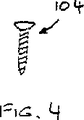
図2から図4に沿って説明すると、コリース骨折における多様な骨破片を整列させ安定させる掌側の固定装置100の第一実施例は、撓骨の掌側に接して置かれることを意図した十分に硬いT字形の板102と、この板102を撓骨の非骨折部に沿って固定するための複数の好ましい骨タッピンねじ104と、板102からコリース骨折の骨破片の中に延びている複数の骨ペグ108とを含んでいる。
【0013】
図2、5及び6に沿ってより具体的に説明する。T字形の板102は、ヘッド部116と、ヘッド部に対して角度をつけて曲げられた細長い本体部118と、骨に接触することが意図された第一面120と、第一面の反対側の第二面122とを形成している。ヘッド部の第一面120は、本体部の第一面のように、平面であることが好ましい。ヘッド部と本体部は互いに角度が付いて曲げられているので、第一面は二つの平面部を好ましく形成する。ヘッド部116と本体部118との間の角度Φは約18°が好ましく、また約25.4mm(約1.00in)の半径で曲げられる(図5)。ヘッド部116の遠位端121は、内側に向かって近位側に好ましく角度が付けられており、その角度は、本体部に直角な線Pに対して、例えば5°である。ヘッド部116は、幅23.19mm(0.913in)で、基部に近い部分(すなわち、本体部との曲げ部分)から遠位端までの寸法が約17.5mm(約0.69in)が好ましく、また本体部は、幅9.53mm(0.375in)で長さ35.6mm(1.40in)が好ましい。T字形の板102の厚さは、約2.49mm(約0.098in)が好ましい。T字形の板102は、Ti−6A−4Vのようなチタン合金から作られることが好適である。
【0014】
本体部118は、骨固定ねじ104をとおして伸ばすための三個の好適な座ぐりねじ用穴124、126、128を含んでいる。第一ねじ用穴124の中心は、本体部の端から5.97mm(0.235in)にあるのが好ましく、第二ねじ用穴126の中心は、本体部の端から16.00mm(0.630in)にあるのが好ましく、第三ねじ用穴128は、ほぼ長円形(あるいはオーバル形)であって、本体部の端から前記長円形の円弧の中心までが25.91mm(1.020in)と26.67mm(1.050in)であることが好ましい。ヘッド部116は、ペグ108を各々通して支えるための4個のねじ山付きのペグ穴130、132、134、136を含んでいる。本発明の第一実施例の第一の好ましい態様にしたがえば、ペグ穴130、132、134、136は、直径2.54mm(0.100in)であることが好ましく、ヘッド部116に沿って非直線的に配列されることが好ましい。またペグ穴は、隣接するペグ穴が第二面に沿って内側から外側の方向で次第に遠位側に与えられるように提供される。さらに詳細に説明すると、本発明の第一実施例の好適な態様にしたがえば、ペグ穴は、ペグ穴130の中心が、線Pから約8.15mm(約0.321in)近位側に、ヘッド部の外側端137から約18.26mm(約0.719in)内側に位置していて、ペグ穴132の中心が、線Pから約7.52mm(約0.296in)近位側に、外側端137から約13.82mm(約0.544in)内側に位置していて、ペグ穴134の中心が、線Pから約6.35mm(約0.250in)近位側に、外側端137から約9.37mm(約0.369in)内側に位置していて、ペグ穴136の中心が、線Pから約4.85mm(約0.191in)近位側に、外側端137から約4.93mm(約0.194in)内側に位置している放物線に沿って配置されることが好ましい。
【0015】
加えて、本発明の第一実施例の第二の好適な態様にしたがえば、ペグ穴は、互いに傾いた(非平行の)軸A1、A2、A3、A4を形成しており、そしてより好ましくは相互に二方向(内側/外側の方向と、近位/遠位の方向)で角度が付けられていることで、すなわち、ペグ穴に一旦挿入されたペグも、相互に二方向で角度が付けられることである。さらに詳しく説明すると、第一ペグ穴130(この穴は、最も近位で最も内側のペグ穴である)の第一軸A1は、ヘッド部116の第一面120に対して垂直に延びているのが好適である。隣接するペグ穴132の軸A2(すなわち第二軸)は、第一軸A1に対して約1〜7°遠位と外側方向に角度が付けられているのが好ましく、さらに好ましくは第一軸A1に対して約2.5°遠位と外側方向に角度が付けられていることである。第二ペグ穴132の横に隣接するペグ穴134の軸A3(すなわち第三軸)は、第一軸A1に対して約7〜13°遠位と外側方向に角度が付けられているのが好ましく、さらに好ましくは第一軸A1に対して約10°遠位と外側方向に角度が付けられていることである。第三ペグ穴132の横に隣接するペグ穴134の軸A4(すなわち第四軸)は、第一軸A1に対して約10〜30°遠位と外側方向に角度が付けられているのが好ましく、さらに好ましくは第一軸A1に対して約20°遠位と外側方向に角度が付けられていることである。ヘッド部116の第二面は、ペグ穴130、132、134、136の遠位側で面取りされているのが好ましい。
【0016】
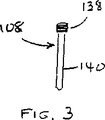
図3に戻ってこれを参照すると、ペグ108は、全長約22.15mm(約0.872in)であることが好ましく、各々が、ペグ穴130、132、134、136のねじ山にねじ結合できるようになったねじ山付き頭部138を持っていて、また比較的滑らかなねじ山なしの円柱状のシャフト(シャフト部)140を持っている。シャフト140は、約1.71mm(約0.0675in)の直径と約19.43mm(約0.765in)の長さであることが好ましい。このような寸法は、骨が正しく治癒できるようにペグが骨破片を適切に支えることを可能にする。また、ペグ108は、チタン合金から作られることが好ましく、そして骨の治癒に悪影響を与えないような骨との境界面を提供するために、例えば窒化チタンのようなセラミックでコーティングされてもよい。
【0017】
図7、8を参照すると、装置100は、掌側の板102の第二面122に一時的に置かれるガイド板146も含んでおり、またこのガイド板146は、ドリルを望ましい方向で骨破片の中へ導くために、ペグ穴の軸A1、A2、A3、A4と同一方向のガイド穴148、150、152、154(図8の重なりあった断面図に図示される)を含んでいる。つまり、ガイド穴がペグ穴と共に、ドリル(図示されない)を所望のピン方向でドリル穴に正確に案内するために、軸に沿った十分な深さのドリルガイド路を形成する。掌側の板102とガイド板146は、穴あけ工程の間に掌側の板の上でガイド板を一時的に固定するために、掌側の板の第二面の複数の穴156、158のような嵌合要素(図2)と、ガイド板の嵌合面側に複数の突起160(図7)とを備えていることが好ましい。
【0018】
図2から9を参照して説明する。使用時、掌側の板102は第一面120を撓骨の掌側に接して置かれる。骨固定ねじ104(タッピンねじ、または事前にあけられた案内穴の助けで挿入されるねじ)は、撓骨に掌側の板102を固定するために、骨固定ねじ用穴124、126、128をとおって撓骨10の中に挿入される。そして骨破片16、18、20は撓骨10に整列される。次に、ガイド板146が掌側の板の第二面の上に置かれる。ペグ穴とガイド穴によって形成されたガイド路に案内されたドリルが、骨破片16、18、20(骨折の個々の位置と広がり次第であるが、ことによると撓骨と一体の部分も)の中と間に穴をあけ、次にガイド板が取り外される。次いでペグ108が、ペグ穴130、132、134、136をとおって骨破片の中にあけられた穴へ挿入され、そしてペグの頭部が掌側の板にねじ結合される。ペグ108は、傾斜したペグ穴130、132、134、136をとおって延び、撓骨のサブコンデュラボーン(subcondylar bone)の真下に位置して、適正な治癒のために骨破片を支える。その結果掌側の固定装置は骨破片を適切な位置でしっかり固定する。
【0019】
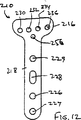
図10〜12を参照すると、掌側の板210の第二実施例が示される。この第二実施例は、第一実施例とほとんど同一であって(類似部品が100番台の符号を持っている)、第一実施例とほとんど同一の方法で使用される。板(掌側の板)210は、全長約59.7mm(約2.35in)であって、この寸法は、第一実施例における寸法より約8.9mm(約0.35in)大きい。この増加した長さは、掌側の板が四個の骨固定ねじ用穴224、226、228、229を好適に含むように、追加の骨固定ねじ用穴229を掌側の板の本体部に収容する。ねじ用穴229の中の追加骨固定ねじは、第一実施例の三個の穴よりも板の安定性を増大させる。板210は、本体部218からヘッド部216までの厚さに対してテ−パが好ましく付けられている。好ましいテーパは、近位の本体部218の厚さ約2.49mm(約0.098in)と、ヘッド部216の厚さ約1.98mm(約0.078in)とを提供する。テーパは、掌側の板の重量を軽減するように、また改善された腱隙間を提供するように、ヘッド部216の厚さを本体部に比較して減少させる。ヘッド部216の遠位端は、遠位端221への増大するテーパ(好ましくはヘッド部の法線に対して約60°)を持つ。遠位端221は、周囲の組織に対する痛みあるいは障害を防ぐために、丸みが付けられる。
【0020】
ヘッド部216は、ペグ208(図13及び14)を個々に通して支えるための四個のねじ山付きのペグ穴230、232、234、236と、ガイド板のアライメントのためのガイド穴256とを含んでいる。本発明の第二実施例の好適な態様にしたがえば、ペグ穴230、232、234、236は、直径2.54mm(0.100in)が好ましく、ヘッド部216に沿って好ましく直線的に配列され、そして隣接するペグ穴が、第一面と第二面において内側から外側の方向で次第に遠位にあるように提供される。図15を参照してさらに具体的に説明すると、本発明の第二実施例の好ましい寸法にしたがえば、ペグ穴230の中心は、線Pから約8.15mm(約0.321in)近位で、ヘッド部の外側端237から約19.05mm(約0.750in)内側に位置していて、ペグ穴232の中心は、線Pから約7.77mm(約0.306in)近位で、ヘッド部の外側端237から約14.15mm(約0.557in)内側に位置していて、ペグ穴234の中心は、線Pから約7.34mm(約0.289in)近位で、ヘッド部の外側端237から約9.25mm(約0.364in)内側に位置していて、ペグ穴236の中心は、線Pから約6.91mm(約0.272in)近位で、ヘッド部の外側端237から約4.34mm(約0.171in)内側に位置している。したがって、掌側の板の各々のペグ穴から遠位端221までの間隔は、第一実施例の場合に比較して大きく、またこの間隔は、テーパが付けられた遠位端221に関して好ましい配列を提供する。
【0021】
図15から24を参照してさらに説明すると、第一実施例の場合のように、ペグ穴は、互いに傾いた軸A1、A2、A3、A4を形成しており、そしてより好ましくは前記の軸は、二つの方向(内側/外側、及び近位/遠位)で互いに角度がついていることである。すなわち、ペグ208が一旦ペグ穴に挿入されると、ペグ208も互いに二方向で角度が付けられる。さらに詳細に説明すると、第一実施例の場合のように、ペグ穴230の第一軸A1は、ヘッド部216の第一面220に対して垂直方向に延びている(図16と21)のが好ましい。ペグ穴232の軸A2は、軸A1に対して、遠位に約1〜7°(図17)、外側に約1〜7°(図22)で好ましく角度が付けられており、さらに好ましくは、軸A1に対して遠位と外側の両方に約2.5°の角度が付けられていることである。ペグ穴234の軸A3は、軸A1に対して、遠位に約7〜13°(図18)、外側に約7〜13°(図23)で好ましく角度が付けられており、さらに好ましくは、軸A1に対して遠位と外側の両方に約10°の角度が付けられていることである。ペグ穴234の軸A4は、軸A1に対して、遠位方向に約10〜30°(図19)、外側に約10〜30°(図24)で好ましく角度が付けられており、さらに好ましくは、軸A1に対して遠位と外側の両方に約20°の角度が付けられていることである。
【0022】
図13と16〜19を参照して説明すると、各ペグ穴は、ペグ208の頭部238を収容するために、座ぐり部270、272、274、276をそれぞれ持っている。座ぐり部270、272は、以下に説明するように、ペグの頭部に応じて、各々好適な深さ約0.76mm(約0.030in)であり、またねじ山が付けられている。座ぐり部274は、好適な深さ約1.07mm(約0.042in)であり、又同様にねじ山が形成されている。座ぐり部276は好適な深さ約1.42mm(約0.056in)であり、又同様にねじ山が付けられている。座ぐり部のそれぞれの深さは、ペグ穴のそれぞれの軸に関係して、ペグ208の頭部238をより良く収容するようにされている。
【0023】
図13と14を参照して説明すると、ペグ208は、全長約22.1mm(約0.872インチ)が好ましく、各々が、ペグ穴230、232、234、236のねじ山にねじ結合できるようになっているねじ山付き頭部238を持っていて、又比較的滑らかなねじ山の無い円柱状のシャフト240を持っている。頭部238は、25.4mm(1in)に総山数44の好適なNo.5ユニファイねじ280を含んでいる。さらに、頭部238は、丸みを付けられ、またペグ穴の中への安定したねじ固定を容易にするために六角穴282を含んでいる。この構造は、ヘッド部216における掌側の板の厚さを減少させている。軸240は、約2.0mm(約0.0792in)の直径と、約19.4mm(約0.765in)の長さであることが好ましい。このような寸法は、骨が正しく治癒できるように、ペグが骨破片を適切に支えることを可能にする。また、ペグ208は、チタン合金から作られることが好ましく、そして骨の治癒に悪影響を与えない強い仕上げを提供するために“チオダイズド”(“tiodized”)であることが好ましい。
【0024】
図25では、第三実施例にしたがった掌側の固定装置300が示されている。掌側の固定装置300では各々のぺグは、各ペグ穴内の角度範囲で関節状に接合され、また前記範囲内の所望の角度で固定されることが可能である。この装置は、掌側の板を撓骨に取付けるために、骨固定ねじ(図示されないが前述された)はもとより、掌側の板302と、四本のペグ302と、四個の止めねじ310とを含んでいる。
【0025】
掌側の板310は、以下に説明するペグ穴の形状を例外として、第一と第二の実施例にほとんど同一であり、また第一実施例とほとんど同一の方法で使用される。掌側の板の中の各々のペグ穴312は、ねじ山316を持った円柱状の上部穴314と、曲率半径を有する下部318とを含んでいる。下部の面320及び/またはペグの頭部の面330は、例えば、電気的、機械的、あるいは化学的磨耗により、もしくは大きな摩擦係数を持った物質かコーティング剤を適用することにより、好ましい粗面である。各々のペグ穴の下部開口322は、円周状のベベル324を含んでいる。
【0026】
図25と26を参照すると、各々のペグ308は、頭部330と円柱状のシャフト332を含んでいる。頭部330の上部334は、ペグ穴312の下部318の半径にほとんど等しい外側半径ROと、比較的小さな内側曲率Riを有するカップ336を含んでいる。頭部330は、約160°の好ましい球体を形成する。シャフト332は、頭部330との交点における小さなテーパ336と、丸みを付けられた先端部338とを含んでいる。ペグ308の好適な製造に従えば、円柱状シャフト332は、最初に球体(図示されない)あるいは半球体(図示されない)を上端部に与えられる。もし球体が与えられたら、球体は半球体に切断される。次いで半球体は、穴を掘られてさらに160°の形状に削られる。最後に、テーパ336が交点で与えられる。
【0027】
図25、27、及び28を参照して説明する。各々の止めねじ310は、上部の六角穴340と、ペグ穴の上部穴314のねじ山316と係合する事ができるような円周状のねじ山342と、カップ336の内側半径とほぼ同一の曲率を有する先端の半球部344とを含んでいて、又ペグ穴312の半径より実質的に小さいことが好ましい。
【0028】
第三実施例にしたがえば、掌側の板が撓骨の上に置かれ、掌側の板の長円形のねじ用穴を介して穴が撓骨の中にあけられる。骨固定ねじが板を介して骨の中に挿入される。そして骨折した骨は、板の下で所望の安定した位置に整えられ、骨固定ねじが締め付けられる。次いで、ペグ穴を通して、外科医が固定用のペグのための穴を骨折部の中にあける。前述した実施例とは異なり、穴は、あらかじめ決まっている範囲内であればどの角度であけても良いが、掌側の板の頭部下面の法線ANに対して20°の範囲内の角度が好ましい。各々の穴は同じ角度あるいは相対的に異なる角度であけてもよい。各々の穴があけられた後に、ペグ308が穴に挿入される。もし必要とするなら、ペグ穴312の下端部(下部開口)322のベベル324とシャフトのテーパ336が、協働してペグを軸ANに対してより大きな角度で方向付けることができるが、これは、ペグ穴とペグシャフトとの干渉が前記ベベルとテーパにより低減されるからである。ペグ308が、ペグ穴の中で適正に配置されたならばすぐに、止めねじ310の一つがペグ穴312の上部穴314にねじ込まれる。半球部344は、ペグの頭部330と接触し、カップ336のくぼみに据えられる。止めねじ310が締め付けられたとき、粗面化されたペグの頭部は、止めねじとペグ穴の下部の粗面化された内面とによって挟まれ、このことによりペグが選択された方向に固定される。他のペグも同様に配置され、そして角度を持って固定される。
【0029】
掌側の固定装置の実施例およびコリース骨折の整列と固定の方法が、本明細書で説明され図示されてきた。本発明の詳細な実施例が説明されてきたが、本発明は、実施例に限定されることを意図されるものではなく、技術が許容するのと同じ程度に広範囲にわたることが意図されており、さらに明細書が同じように読まれることが意図されている。したがって、装置の要素の具体的な材料が開示されてきたが、他の材料も使用されてよいことが理解されるであろう。さらに、掌側の板のねじ用穴と骨固定ねじの具体的な数量が記述されてきたが、ねじ用穴とねじに他の数量が与えられることもあることが理解されるであろう。さらに、ねじ用穴数量より少ないねじが、掌側の板を撓骨へ固定するために使われることもある。又、より少ない、あるいはより多いペグ穴と骨ペグが使用されることもあり、互いに二方向で角度のついた少なくとも二本のペグが与えられることが好ましい。さらに、第一実施例では、ペグ穴が放物線に沿って並んでいるのが好適であったが、ペグ穴が他の曲線に沿って並ぶことも理解されるであろう。さらに、ヘッド部と本体部の間の具体的で好ましい角度が説明されてきたが、他の角度でも使用可能である。また、ペグ穴と線Pとの具体的な間隔が説明されてきたが、ペグ穴が、線Pとの他の間隔を与えられることも理解されるであろう。加えて、具体的で好適な内側/外側と近位/遠位のペグ穴軸角度が説明されてきたが、さらに他の角度が、本発明に従って使用されることも理解されるであろう。又、第一実施例に関しては右手用掌側の板が記述されていて、第二実施例に関しては左手用掌側の板が記述されているが、各々の実施例は、右手用左手用どちらのモデルにも、説明してきたモデルの鏡像であるような代替モデルで、形作られることもあることが認識されるであろう。加えて、ピンが角度を付けられる範囲の20°が説明されたが、ペグ穴とペグは、より大きいか又はより小さい角度範囲となるように変えられてもよい。その上さらに、六角穴が、止めねじに回転力を与えるために止めねじ上にあることが説明されたが、他の回転係合手段、例えば、プラス、マイナス、星型、矩形、あるいは他の形状、が使用されることもあることが理解されるであろう。さらに、実施例からの各々の態様は組み合わされることもある。それゆえ、当業者において本発明は、請求項の精神と範囲を逸脱することなしに修正されてもよいことが、理解されるであろう。
【図面の簡単な説明】
【図1】 図1は、コリース骨折を対象とした手の説明図である。
【図2】 図2は、本発明の第一実施例にしたがった、右手用掌側の固定装置の平面図である。
【図3】 図3は、本発明の掌側の固定装置の第一実施例にしたがった、骨ペグの側面図である。
【図4】 図4は、本発明の掌側の固定装置の骨固定ねじの側面図である。
【図5】 図5は、本発明の第一実施例にしたがった、掌側の固定装置の右手用掌側の板の側面図である。
【図6】 図6は、本発明の第一実施例にしたがった、掌側の固定装置の右手用掌側の板の前面図である。
【図7】 図7は、本発明の固定装置の第一実施例にしたがった、右手用掌側の板とガイド板の分解側面図である。
【図8】 図8は、本発明にしたがって、ドリルのガイド通路を提供するために右手用掌側の板の上に配置されたガイド板の側面図である。
【図9】 図9は、コリース骨折に整列と安定を提供した掌側の固定装置の第一実施例の説明図である。
【図10】 図10は、本発明の第二実施例にしたがった、左手用掌側の固定装置の平面図である。
【図11】 図11は、本発明の第二実施例にしたがった、左手用掌側の固定装置の外側の側面図である。
【図12】 図12は、本発明の第二実施例にしたがった、左手用掌側の固定装置の下面図である。
【図13】 図13は、本発明の掌側の固定装置の第二実施例にしたがった、骨ペグの拡大側面図である。
【図14】 図14は、図13の骨ペグの上端図である。
【図15】 図15は、本発明の掌側の固定装置の第二実施例にしたがった、左手用掌側の板のヘッド部の第一部分平面図である。
【図16】 図16は、図15における直線16−16で切断した断面図である。
【図17】 図17は、図15における直線17−17で切断した断面図である。
【図18】 図18は、図15における直線18−18で切断した断面図である。
【図19】 図19は、図15における直線19−19で切断した断面図である。
【図20】 図20は、本発明の掌側の固定装置の第二実施例にしたがった、左手用掌側の板のヘッド部の第二部分平面図である。
【図21】 図21は、図20における直線21−21で切断した断面図である。
【図22】 図22は、図20における直線22−22で切断した断面図である。
【図23】 図23は、図20における直線23−23で切断した断面図である。
【図24】 図24は、図20における直線24−24で切断した断面図である。
【図25】 図25は、本発明の掌側の固定装置の第三実施例の遠位端部を部分的に切断した縦断面図である。
【図26】 図26は、本発明の第三実施例にしたがった、骨ペグの上斜視図である。
【図27】 図27は、本発明の第三実施例にしたがった、止めねじの上斜視図および下斜視図である。
【図28】 図28は、本発明の第三実施例にしたがった、止めねじの上斜視図および下斜視図である。[0001]
Background of the invention
1. Field of the invention
The present invention relates broadly to surgical devices. More particularly, the present invention relates to a bone anchoring device, in particular a anchoring device adapted to fix a collie (or distal radius) fracture.
[0002]
2. Technical status
This will be described with reference to FIG. A Collise fracture is a fracture that results from the application of compressive force to the distal radius 10, and the fracture is a rearward displacement of the
[0003]
Alignment and fixation are commonly performed in one of several ways, such as casting, external fixation devices, ligation between bones, and plate fixation. Although the cast is non-invasive, it may not be able to maintain the alignment of the fracture where there are numerous bone fragments. Therefore, an external fixing device may be used instead. The external fixation device utilizes a method known as ligament taxis. Ligament taxis provides a scattered force across the junction and aligns the fracture based on the tension generated in the surrounding ligaments. However, although an external fixation device can maintain the position of the wrist bone, it may still be difficult to provide the bone in the correct alignment first for certain types of fractures. In addition, external fixation devices are often not suitable for fractures where a large number of bone fragments have occurred. The ligation method between bones is an invasive technique where screws are placed in various bone fragments and then the screws are tied together with a wire like a brace. This is a difficult and time consuming technique. Furthermore, if the brace is not fairly complex, the fracture will not be fixed correctly. In order to provide stable fixation to bone fragments, plate fixation generally involves a set of metal plates that are generally in contact with the back side of the bone and a plate that extends from the plate into a hole in the bone fragment. Use parallel pins. However, currently available flat plate devices cannot provide the desired alignment and fixation.
[0004]
Therefore, it is an object of the present invention to provide an apparatus for improved fixation and alignment for collie fractures.
[0005]
Another object of the present invention is to desirably align and secure multiple bone fragments in the distal radius fracture to provide proper healing. Palm side Is to provide a fixing device.
[0006]
Another object of the present invention is to be precisely adjustable to provide a customizable frame structure for bone fragment fixation. Palm side Is to provide a fixing device.
[0007]
Details will be described below in accordance with these purposes. Palm side The fixing device includes a T-shaped plate intended to be placed in contact with the palm side of the radius, a plurality of bone fixing screws for fixing the plate along the non-fracture portion of the radius, and a collie from the plate. There is provided what typically includes a plurality of bone pegs (pegs) extending into a bone fragment due to a fracture.
[0008]
The plate is a generally T-shaped plate that includes an elongated body portion, a head portion bent at an angle with respect to the body portion, and a first surface intended to contact the bone; And a second surface opposite to the first surface. The body includes a plurality of screw counterbores for extending through the bone fixation screws. The head portion includes a plurality of threaded peg holes that are adapted to be supported through the pegs. In the first embodiment, the peg holes are preferably arranged non-linearly. In the second embodiment, the peg holes are preferably arranged linearly. In both embodiments, the peg holes are arranged to gradually move away from the inside to the outside on the second surface. The third example had peg holes arranged according to the first and second examples Palm side The pegs are adjustable in relation to the peg holes and can be freely fixed in selectable directions.
[0009]
When using Palm side The plate is placed with its first surface in contact with the palm side of the radius, and the bone fixation screw is Palm side In order to fix the plate to the radius, it is inserted into the bone fixing screw hole. The bone fragments are aligned and the guide plate Palm side Placed on the second side of the board. A drill pierces the bone fragment.
[0010]
The peg is then inserted into the bone hole through the peg hole. In some embodiments, the peg head is Palm side It can be screwed to the plate. In other embodiments, the peg is inserted into the peg hole and inserted into the drilled hole at an angle selected by the surgeon, and then a set screw is placed in the selected direction on the peg. Palm side Inserted into each peg to stop on the plate. Thereby Palm side The fixation device stabilizes and fixes bone debris at an appropriate position.
[0011]
Further objects and advantages of the present invention will become apparent to those skilled in the art by reference to the detailed description taken in conjunction with the accompanying drawings.
[0012]
Detailed Description of the Preferred Embodiment
Referring to FIGS. 2-4, the various bone fragments in the Collies fracture are aligned and stabilized. Palm side The first embodiment of the
[0013]
More specific description will be given with reference to FIGS. The T-shaped
[0014]
The
[0015]
In addition, according to the second preferred embodiment of the first embodiment of the present invention, the peg holes form axes A1, A2, A3, A4 that are inclined (non-parallel) to each other, and more Preferably, the pegs are angled in two directions (inner / outer and proximal / distal directions), i.e., the pegs once inserted into the peg holes are also angled in two directions. Is attached. More specifically, the
[0016]
Referring back to FIG. 3, the
[0017]
Referring to FIGS. 7 and 8, the
[0018]
This will be described with reference to FIGS. while using it, Palm side The
[0019]
With reference to FIGS. Palm side A second embodiment of the
[0020]
The
[0021]
Further description with reference to FIGS. 15 to 24, as in the first embodiment, the peg holes form axes A1, A2, A3, A4 which are inclined with respect to each other, and more preferably said axes. Is angled with respect to each other in two directions (inside / outside and proximal / distal). That is, once the
[0022]
13 and 16-19, each peg hole has
[0023]
Referring to FIGS. 13 and 14, the
[0024]
In FIG. 25, according to the third embodiment. Palm side A fixing
[0025]
Palm side The
[0026]
Referring to FIGS. 25 and 26, each
[0027]
This will be described with reference to FIGS. Each
[0028]
According to the third embodiment, Palm side Plate is placed on the bone Palm side A hole is drilled into the flexure through an oval screw hole in the plate. A bone fixation screw is inserted into the bone through the plate. The fractured bone is then adjusted to the desired stable position under the plate and the bone fixation screw is tightened. The surgeon then drills a hole for the fixation peg into the fracture through the peg hole. Unlike the embodiment described above, the hole may be drilled at any angle within a predetermined range, Palm side An angle within a range of 20 ° with respect to the normal line AN of the lower surface of the head of the plate is preferred. Each hole may be drilled at the same angle or at a relatively different angle. After each hole is drilled, a
[0029]
Palm side Examples of fixation devices and methods for aligning and fixing collie fractures have been described and illustrated herein. Although detailed embodiments of the present invention have been described, the present invention is not intended to be limited to the embodiments, but is intended to be as broad as the technology allows. It is further intended that the specification be read in the same way. Thus, while specific materials for device elements have been disclosed, it will be understood that other materials may be used. further, Palm side Although specific numbers of screw holes and bone fixation screws have been described, it will be understood that other numbers may be provided for the screw holes and screws. Furthermore, there are fewer screws than screw holes. Palm side Sometimes used to secure the plate to the bone. Also, fewer or more peg holes and bone pegs may be used, preferably providing at least two pegs that are angled in two directions. Furthermore, in the first embodiment, it was preferred that the peg holes were aligned along a parabola, but it will be understood that the peg holes are aligned along other curves. Furthermore, while specific and preferred angles between the head and body have been described, other angles can be used. Also, although specific spacing between the peg holes and the line P has been described, it will be understood that the peg holes can be provided with other spacings with the line P. In addition, although specific preferred inner / outer and proximal / distal peg hole axis angles have been described, it will be understood that still other angles may be used in accordance with the present invention. Also, for the first embodiment, for the right hand Palm side The left plate is described for the second embodiment. Palm side However, it will be appreciated that each embodiment may be shaped with an alternative model, which is a mirror image of the model described, for both right hand and left hand models. I will. In addition, although the 20 ° range in which the pins are angled has been described, the peg holes and pegs may be varied to provide a larger or smaller angular range. Furthermore, although it has been described that the hexagonal hole is on the set screw to provide rotational force to the set screw, other rotational engagement means such as plus, minus, star, rectangular, or other It will be understood that shapes may be used. Furthermore, each aspect from the examples may be combined. Thus, it will be appreciated by one skilled in the art that the present invention may be modified without departing from the spirit and scope of the following claims.
[Brief description of the drawings]
FIG. 1 is an explanatory diagram of a hand for a collie fracture.
FIG. 2 shows a right hand according to the first embodiment of the present invention. Palm side It is a top view of the fixing device.
FIG. 3 illustrates the present invention. Palm side FIG. 3 is a side view of a bone peg according to a first embodiment of the fixation device of
FIG. 4 is a diagram of the present invention. Palm side It is a side view of the bone fixing screw of the fixing device.
FIG. 5 shows a first embodiment of the present invention, Palm side Fixing device for right hand Palm side It is a side view of the board of.
FIG. 6 shows a first embodiment of the present invention, Palm side Fixing device for right hand Palm side It is a front view of the board of.
FIG. 7 shows a right hand according to a first embodiment of the fixing device of the present invention. Palm side It is a decomposition | disassembly side view of this board and a guide board.
FIG. 8 is for a right hand to provide a guide passage for a drill according to the present invention. Palm side It is a side view of the guide plate arrange | positioned on this board.
FIG. 9 provided alignment and stability for the Collies fracture Palm side It is explanatory drawing of the 1st Example of this fixing device.
FIG. 10 shows a left hand according to a second embodiment of the present invention Palm side It is a top view of the fixing device.
FIG. 11 shows a left hand according to the second embodiment of the present invention. Palm side It is a side view of the outer side of this fixing device.
FIG. 12 shows a left hand according to a second embodiment of the present invention Palm side It is a bottom view of the fixing device.
FIG. 13 is a diagram of the present invention. Palm side FIG. 6 is an enlarged side view of a bone peg according to a second embodiment of the fixation device.
FIG. 14 is a top view of the bone peg of FIG. 13;
FIG. 15 is a diagram of the present invention. Palm side According to the second embodiment of the fixing device for the left hand Palm side It is a 1st partial top view of the head part of this board.
FIG. 16 is a cross-sectional view taken along line 16-16 in FIG.
FIG. 17 is a cross-sectional view taken along line 17-17 in FIG.
FIG. 18 is a cross-sectional view taken along line 18-18 in FIG.
FIG. 19 is a cross-sectional view taken along line 19-19 in FIG.
FIG. 20 is a diagram of the present invention. Palm side According to the second embodiment of the fixing device for the left hand Palm side It is a 2nd partial top view of the head part of this board.
FIG. 21 is a cross-sectional view taken along line 21-21 in FIG.
FIG. 22 is a cross-sectional view taken along line 22-22 in FIG.
FIG. 23 is a cross-sectional view taken along line 23-23 in FIG.
FIG. 24 is a cross-sectional view taken along line 24-24 in FIG.
FIG. 25 is a diagram of the present invention. Palm side It is the longitudinal cross-sectional view which cut | disconnected the distal end part of the 3rd Example of this fixing device partially.
FIG. 26 is a top perspective view of a bone peg according to a third embodiment of the present invention.
FIG. 27 is a top perspective view and a bottom perspective view of a set screw according to a third embodiment of the present invention.
FIG. 28 is a top perspective view and a bottom perspective view of a set screw according to a third embodiment of the present invention.
Claims (41)
遠位のヘッド部と、前記ヘッド部に対して曲げられた近位の本体部とを含む十分に硬い板であって、前記ヘッド部が、固定用のペグを中で個々に支えるようになっている、ねじ山付きの複数のペグ穴を形成しており、前記ペグ穴が、少なくとも四本が、前記ヘッド部の、内側から外側方向にかつ近位から遠位の方向に、互いに傾いている複数の軸を形成しており、前記本体部が、少なくとも一個のねじ用穴を含んだ、十分に硬い板を具備し、
前記ペグ穴が、概ね内側から外側方向に配列されて、隣接するペグ穴に対して次に続く外側のペグ穴が遠位に位置するようになっており、
前記ヘッド部が下面を含んでいて、複数の前記ペグ穴の第一ペグ穴が、前記下面に対してほぼ垂直に延びている、前記複数の軸の第一軸を形成しており、
複数の前記ペグ穴の第二ペグ穴が、第一軸に対して、遠位に約1〜7°と外側に約1〜7°の角度が付けられている、前記複数の軸の第二軸を形成していて、
複数の前記ペグ穴の第三ペグ穴が、第一軸に対して、遠位に約7〜13°と外側に約7〜13°の角度が付けられている、前記複数の軸の第三軸を形成していて、
複数の前記ペグ穴の第四ペグ穴が、第一軸に対して、遠位に約10〜30°と外側に約10〜30°の角度が付けられている、前記複数の軸の第四軸を形成しており、
前記第一ペグ穴が最も内側にあり、前記第二ペグ穴が前記第一ペグ穴の外側に隣接していて、前記第三ペグ穴が前記第二ペグ穴の外側に隣接していて、前記第四ペグ穴が前記第三ペグ穴の外側に隣接しているところの、
掌側の固定板。 In the fixed plate on the palm side ,
A sufficiently stiff plate including a distal head portion and a proximal body portion bent relative to the head portion, the head portion individually supporting a locking peg therein; A plurality of threaded peg holes, wherein at least four of the peg holes are inclined relative to each other from the inside to the outside and from the proximal to the distal of the head portion. A plurality of shafts, wherein the body includes a sufficiently hard plate including at least one screw hole;
The peg holes are generally arranged from the inside to the outside so that the next outer peg hole is located distal to the adjacent peg hole;
The head portion includes a lower surface, and the first peg holes of the plurality of peg holes form a first axis of the plurality of axes extending substantially perpendicular to the lower surface;
A plurality of second peg holes of the plurality of peg holes, wherein the second peg holes of the plurality of axes are angled about 1-7 ° distally and about 1-7 ° outwardly relative to the first axis; Forming an axis,
A third peg hole of the plurality of peg holes, wherein the third peg hole of the plurality of peg holes is angled about 7-13 ° distally and about 7-13 ° outwardly relative to the first axis. Forming an axis,
A fourth peg hole of the plurality of peg holes, wherein the fourth peg hole of the plurality of axes is angled about 10-30 ° distally and about 10-30 ° outwardly relative to the first axis. Forming the axis,
The first peg hole is on the innermost side, the second peg hole is adjacent to the outside of the first peg hole, the third peg hole is adjacent to the outside of the second peg hole, and Where the fourth peg hole is adjacent to the outside of the third peg hole,
Fixed plate on the palm side .
前記ペグ穴が各々、概ね放物線に沿って配置された中心を持っているところの、掌側の固定板。The fixing plate on the palm side according to claim 1,
A fixing plate on the palm side , wherein each of the peg holes has a center disposed substantially along a parabola.
前記ヘッド部が、ちょうど四個のペグ穴を含んでいるところの、掌側の固定板。The fixing plate on the palm side according to claim 1,
A fixing plate on the palm side , wherein the head part includes exactly four peg holes.
複数の前記ペグ穴の第一ペグ穴が、前記下面に対して垂直方向に延びる、前記複数の軸の第一軸を形成しており、
複数の前記ペグ穴の第二ペグ穴が、第一軸に対して、遠位に約5°と外側に約7.5°の角度が付けられている、前記複数の軸の第二軸を形成していて、
複数の前記ペグ穴の第三ペグ穴が、第一軸に対して、遠位に約10°と外側に約10°の角度が付けられている、前記複数の軸の第三軸を形成していて、
複数の前記ペグ穴の第四ペグ穴が、第一軸に対して、遠位に約20°と外側に約20°の角度が付けられている、前記複数の軸の第四軸を形成しているところの、
掌側の固定板。The palm-side fixing plate according to claim 3,
First peg holes of the plurality of peg holes form a first axis of the plurality of axes extending in a direction perpendicular to the lower surface;
The second peg holes of the plurality of peg holes are angled about 5 ° distally and about 7.5 ° outward with respect to the first axis. Formed
A third peg hole of the plurality of peg holes forms a third axis of the plurality of axes that is angled about 10 ° distally and about 10 ° outwardly relative to the first axis. And
A fourth peg hole of the plurality of peg holes forms a fourth axis of the plurality of axes that is angled about 20 ° distally and about 20 ° outwardly relative to the first axis. Where
Fixed plate on the palm side .
複数の前記ペグ穴の第一ペグ穴が、前記下面に対してほぼ垂直方向に延びる、前記複数の軸の第一軸を形成しており、
複数の前記ペグ穴の第二ペグ穴が、第一軸に対して、遠位に約2.5°と外側に約2.5°の角度が付けられている、前記複数の軸の第二軸を形成していて、
複数の前記ペグ穴の第三ペグ穴が、第一軸に対して、遠位に約10°と外側に約10°の角度が付けられている、前記複数の軸の第三軸を形成していて、
複数の前記ペグ穴の第四ペグ穴が、第一軸に対して、遠位に約20°と外側に約20°の角度が付けられている、前記複数の軸の第四軸を形成しているところの、
掌側の固定板。The fixing plate on the palm side according to claim 1,
First peg holes of the plurality of peg holes form a first axis of the plurality of axes extending in a direction substantially perpendicular to the lower surface;
A second peg hole of the plurality of peg holes angled about 2.5 ° distally and about 2.5 ° outwardly relative to the first axis; Forming an axis,
A third peg hole of the plurality of peg holes forms a third axis of the plurality of axes that is angled about 10 ° distally and about 10 ° outwardly relative to the first axis. And
A fourth peg hole of the plurality of peg holes forms a fourth axis of the plurality of axes that is angled about 20 ° distally and about 20 ° outwardly relative to the first axis. Where
Fixed plate on the palm side .
前記ヘッド部が、前記本体部に対して約18°の角度で曲げられているところの、掌側の固定板。The fixing plate on the palm side according to claim 1,
A palm-side fixing plate in which the head portion is bent at an angle of about 18 ° with respect to the main body portion.
前記ヘッド部と前記本体部が、相互の関係が概ねT字形状を備えていて、前記本体部と前記ヘッド部が交わっている、掌側の固定板。The fixing plate on the palm side according to claim 1,
A palm-side fixing plate in which the head part and the main body part have a substantially T-shaped relationship, and the main body part and the head part intersect.
前記掌側の固定板がチタン合金から作られているところの、掌側の固定板。The fixing plate on the palm side according to claim 1,
Where the fixing plate of the palm side is made of titanium alloy, the palm side of the fixed plate.
遠位のヘッド部と、前記ヘッド部に対して曲げられた近位の本体部とを含む十分に硬い板であって、
前記ヘッド部が、固定用のペグを個々に通して支えるようにされた、ねじ山付きの複数のペグ穴を形成しており、
前記ペグ穴が、隣接するペグ穴に対して次に続く外側のペグ穴が遠位に位置するように、概ね内側から外側方向に直線的に配列されていて、前記本体部が、少なくとも一個のねじ用穴を含んだ、十分に硬い板を具備し、
前記ペグ穴が、少なくとも四本が、前記ヘッド部の、内側から外側方向にかつ近位から遠位の方向に、互いに傾いている複数の軸を形成しており、
前記ヘッド部が下面を含んでいて、複数の前記ペグ穴の第一ペグ穴が、前記下面に対してほぼ垂直に延びている、前記複数の軸の第一軸を形成しており、
複数の前記ペグ穴の第二ペグ穴が、第一軸に対して、遠位に約1〜7°と外側に約1〜7°の角度が付けられている、前記複数の軸の第二軸を形成していて、
複数の前記ペグ穴の第三ペグ穴が、第一軸に対して、遠位に約7〜13°と外側に約7〜13°の角度が付けられている、前記複数の軸の第三軸を形成していて、
複数の前記ペグ穴の第四ペグ穴が、第一軸に対して、遠位に約10〜30°と外側に約10〜30°の角度が付けられている、前記複数の軸の第四軸を形成しており、
前記第一ペグ穴が最も内側にあり、前記第二ペグ穴が前記第一ペグ穴の外側に隣接していて、前記第三ペグ穴が前記第二ペグ穴の外側に隣接していて、前記第四ペグ穴が前記第三ペグ穴の外側に隣接しているところの、
掌側の固定板。 In the fixed plate on the palm side ,
A sufficiently stiff plate comprising a distal head portion and a proximal body portion bent with respect to the head portion,
The head portion forms a plurality of threaded peg holes adapted to individually support and hold the fixing pegs;
The peg holes are arranged generally linearly from the inside to the outside so that the next outer peg hole is located distally with respect to an adjacent peg hole, and the body portion includes at least one peg hole. It has a sufficiently hard plate with screw holes,
The peg hole forms a plurality of axes at least four of which are inclined with respect to each other from the inside to the outside and from the proximal to the distal of the head portion;
The head portion includes a lower surface, and the first peg holes of the plurality of peg holes form a first axis of the plurality of axes extending substantially perpendicular to the lower surface;
A plurality of second peg holes of the plurality of peg holes, wherein the second peg holes of the plurality of axes are angled about 1-7 ° distally and about 1-7 ° outwardly relative to the first axis; Forming an axis,
A third peg hole of the plurality of peg holes, wherein the third peg hole of the plurality of peg holes is angled about 7-13 ° distally and about 7-13 ° outwardly relative to the first axis. Forming an axis,
A fourth peg hole of the plurality of peg holes, wherein the fourth peg hole of the plurality of axes is angled about 10-30 ° distally and about 10-30 ° outwardly relative to the first axis. Forming the axis,
The first peg hole is on the innermost side, the second peg hole is adjacent to the outside of the first peg hole, the third peg hole is adjacent to the outside of the second peg hole, and Where the fourth peg hole is adjacent to the outside of the third peg hole,
Fixed plate on the palm side .
複数の前記ペグ穴の第一ペグ穴が、前記下面に対してほぼ垂直方向に延びる、前記複数の軸の第一軸を形成しており、
複数の前記ペグ穴の第二ペグ穴が、第一軸に対して、遠位に約2.5°と外側に約2.5°の角度が付けられている、前記複数の軸の第二軸を形成していて、
複数の前記ペグ穴の第三ペグ穴が、第一軸に対して、遠位に約10°と外側に約10°の角度が付けられている、前記複数の軸の第三軸を形成していて、
複数の前記ペグ穴の第四ペグ穴が、第一軸に対して、遠位に約20°と外側に約20°の角度が付けられている、前記複数の軸の第四軸を形成しているところの、
掌側の固定板。The palm-side fixing plate according to claim 9,
First peg holes of the plurality of peg holes form a first axis of the plurality of axes extending in a direction substantially perpendicular to the lower surface;
A second peg hole of the plurality of peg holes angled about 2.5 ° distally and about 2.5 ° outwardly relative to the first axis; Forming an axis,
A third peg hole of the plurality of peg holes forms a third axis of the plurality of axes that is angled about 10 ° distally and about 10 ° outwardly relative to the first axis. And
A fourth peg hole of the plurality of peg holes forms a fourth axis of the plurality of axes that is angled about 20 ° distally and about 20 ° outwardly relative to the first axis. Where
Fixed plate on the palm side .
前記ヘッド部が、前記本体部に対して約18°の角度で曲げられているところの、掌側の固定板。The palm-side fixing plate according to claim 9,
A palm-side fixing plate in which the head portion is bent at an angle of about 18 ° with respect to the main body portion.
前記ヘッド部と前記本体部が、相互の関係が概ねT字形状を備えていて、前記本体部と前記ヘッド部が交わっている、掌側の固定板。The palm-side fixing plate according to claim 9,
A palm-side fixing plate in which the head part and the main body part have a substantially T-shaped relationship, and the main body part and the head part intersect.
遠位のヘッド部と近位の本体部とを含む十分に硬い板であって、
前記ヘッド部が、固定用のペグを中で個々に支えるようになっているねじ山付きの複数のペグ穴を形成しており、
前記ヘッド部が、内側と外側を形成しており、また前記ペグ穴が、概ね内側から外側方向に配列されて、隣接するペグ穴に対して次に続く外側のペグ穴が遠位に位置するようになっている、十分に硬い板を具備し、
複数の前記ペグ穴が、複数の軸を形成していて、前記複数の軸の第一軸が、前記ヘッド部の下面に対してほぼ垂直方向に延びていて、
前記複数の軸の第二軸が、第一軸に対して、遠位に約1〜7°と外側に約1〜7°の角度が付けられていて、
前記複数の軸の第三軸が、第一軸に対して、遠位に約7〜13°と外側に約7〜13°の角度が付けられていて、
前記複数の軸の第四軸が、第一軸に対して、遠位に約10〜30°と外側に約10〜30°の角度が付けられていて、
前記本体部が、少なくとも一個のねじ用穴を含んでおり、
前記第一ペグ穴が最も内側にあり、前記第二ペグ穴が前記第一ペグ穴の外側に隣接していて、前記第三ペグ穴が前記第二ペグ穴の外側に隣接していて、前記第四ペグ穴が前記第三ペグ穴の外側に隣接しているところの、
掌側の固定板。 In the fixed plate on the palm side ,
A sufficiently stiff plate including a distal head portion and a proximal body portion,
The head portion forms a plurality of threaded peg holes that individually support the fixing pegs therein;
The head portion forms an inner side and an outer side, and the peg holes are generally arranged from the inner side to the outer side, and the outer peg hole that follows the adjacent peg hole is located distally. Equipped with a sufficiently hard plate,
The plurality of peg holes form a plurality of axes, and the first axes of the plurality of axes extend in a direction substantially perpendicular to the lower surface of the head portion,
A second axis of the plurality of axes is angled about 1-7 ° distally and about 1-7 ° outwardly relative to the first axis;
A third axis of the plurality of axes is angled about 7-13 ° distally and about 7-13 ° outwardly relative to the first axis;
A fourth axis of the plurality of axes is angled about 10-30 ° distally and about 10-30 ° outwardly with respect to the first axis;
The main body includes at least one screw hole;
The first peg hole is on the innermost side, the second peg hole is adjacent to the outside of the first peg hole, the third peg hole is adjacent to the outside of the second peg hole, and Where the fourth peg hole is adjacent to the outside of the third peg hole,
Fixed plate on the palm side .
前記第二軸が、第一軸に対して、遠位に約2.5°と外側に約2.5°の角度が付けられており、
前記第三軸が、第一軸に対して、遠位に約10°と外側に約10°の角度が付けられていて、
前記第四軸が、第一軸に対して、遠位に約20°と外側に約20°の角度が付けられているところの、掌側の固定板。The palm-side fixing plate according to claim 13,
The second axis is angled about 2.5 ° distally and about 2.5 ° outwardly relative to the first axis;
The third axis is angled about 10 ° distally and about 10 ° outwardly relative to the first axis;
A palm-side fixation plate, wherein the fourth axis is angled about 20 ° distally and about 20 ° outwardly relative to the first axis.
前記ペグ穴が直線的に配列されているところの、掌側の固定板。The palm-side fixing plate according to claim 13,
A palm-side fixing plate in which the peg holes are linearly arranged.
前記ペグ穴が曲線上に配置されたところの、掌側の固定板。The palm-side fixing plate according to claim 13,
A palm-side fixing plate in which the peg holes are arranged on a curve.
前記曲線が放物線であるところの、掌側の固定板。The palm-side fixing plate according to claim 16,
A fixed plate on the palm side where the curve is a parabola.
a)遠位のヘッド部と近位の本体部とを含む十分に硬い板であって、前記ヘッド部が、複数の軸を形成する複数のねじ山付きのペグ穴を形成しており、前記複数の軸の中の少なくとも四本が、前記ヘッド部の、内側から外側方向にかつ近位から遠位の方向に、互いに傾いていて、前記本体部が少なくとも一個のねじ用穴を含んでいる、十分に硬い板と、
b)各々がねじ山付き頭部とシャフト部を持っている複数のペグであって、ねじ山付き前記頭部が、ねじ山付き前記ペグ穴と係合する大きさに作られていて、また、前記シャフト部の各々が前記複数の軸のそれぞれの一本に沿って延びるように、前記シャフト部が、前記ペグ穴を通して支えられる大きさに作られている、複数のペグと、
を具備し、
前記ペグ穴が、概ね内側から外側方向に配列されて、隣接するペグ穴に対して次に続く外側のペグ穴が遠位に位置するようになっており、
前記ヘッド部が下面を含んでいて、複数の前記ペグ穴の第一ペグ穴が、前記下面に対してほぼ垂直に延びている、前記複数の軸の第一軸を形成しており、
複数の前記ペグ穴の第二ペグ穴が、第一軸に対して、遠位に約1〜7°と外側に約1〜7°の角度が付けられている、前記複数の軸の第二軸を形成していて、
複数の前記ペグ穴の第三ペグ穴が、第一軸に対して、遠位に約7〜13°と外側に約7〜13°の角度が付けられている、前記複数の軸の第三軸を形成していて、
複数の前記ペグ穴の第四ペグ穴が、第一軸に対して、遠位に約10〜30°と外側に約10〜30°の角度が付けられている、前記複数の軸の第四軸を形成しており、
前記第一ペグ穴が最も内側にあり、前記第二ペグ穴が前記第一ペグ穴の外側に隣接していて、前記第三ペグ穴が前記第二ペグ穴の外側に隣接していて、前記第四ペグ穴が前記第三ペグ穴の外側に隣接しているところの、
掌側の固定装置。 In the fixing device on the palm side ,
a) a sufficiently stiff plate including a distal head portion and a proximal body portion, wherein the head portion defines a plurality of threaded peg holes forming a plurality of axes; At least four of the plurality of shafts are inclined with respect to each other from the inside to the outside and from the proximal to the distal direction of the head portion, and the body portion includes at least one screw hole. A sufficiently hard board,
b) a plurality of pegs each having a threaded head and a shaft portion, the threaded head being sized to engage the threaded peg hole; A plurality of pegs that are sized to be supported through the peg holes such that each of the shaft portions extends along a respective one of the plurality of axes;
Comprising
The peg holes are generally arranged from the inside to the outside so that the next outer peg hole is located distal to the adjacent peg hole;
The head portion includes a lower surface, and the first peg holes of the plurality of peg holes form a first axis of the plurality of axes extending substantially perpendicular to the lower surface;
A plurality of second peg holes of the plurality of peg holes, wherein the second peg holes of the plurality of axes are angled about 1-7 ° distally and about 1-7 ° outwardly relative to the first axis; Forming an axis,
A third peg hole of the plurality of peg holes, wherein the third peg hole of the plurality of peg holes is angled about 7-13 ° distally and about 7-13 ° outwardly relative to the first axis. Forming an axis,
A fourth peg hole of the plurality of peg holes, wherein the fourth peg hole of the plurality of axes is angled about 10-30 ° distally and about 10-30 ° outwardly relative to the first axis. Forming the axis,
The first peg hole is on the innermost side, the second peg hole is adjacent to the outside of the first peg hole, the third peg hole is adjacent to the outside of the second peg hole, and Where the fourth peg hole is adjacent to the outside of the third peg hole,
A fixing device on the palm side .
前記ペグの各々の前記頭部が、六角穴を含んでいるところの、固定装置。The palm-side fixing device according to claim 18,
A fixation device wherein each head of the peg includes a hexagonal hole.
前記ペグの各々の前記頭部が、丸い頭を含んでいるところの、掌側の固定装置。The palm-side fixing device according to claim 18,
A fixation device on the palm side , wherein the head of each of the pegs includes a round head.
前記ペグの各々の前記頭部が、No.5ユニファイねじを含んでいるところの、掌側の固定装置。The palm-side fixing device according to claim 18,
The head of each of the pegs is No. A palm-side fixing device that includes 5 unified screws.
前記ペグの各々の前記シャフト部が、ねじ山がない円柱であるところの、掌側の固定装置。The palm-side fixing device according to claim 18,
A fixing device on the palm side , wherein each shaft portion of the peg is a cylinder without a thread.
c)前記少なくとも一個のねじ用穴で支えられるようになっている少なくとも一個のねじを更に具備する、掌側の固定装置。The palm-side fixing device according to claim 18,
c) A palm-side fixing device further comprising at least one screw adapted to be supported by the at least one screw hole.
前記少なくとも一個のねじがタッピンねじであるところの、掌側の固定装置。The palm-side fixing device according to claim 23,
A palm-side fixing device, wherein the at least one screw is a tapping screw.
c)掌側の前記板の少なくとも一部分の上に置かれるようになっていて、複数のガイド穴を含んでいるガイド板であって、前記ガイド板が掌側の前記板の上に置かれた場合、前記ガイド穴と前記ペグ穴が共同してドリルを軸方向に通して導くようにされたドリルガイドを形成する、ガイド板を更に具備する、掌側の固定装置。The palm-side fixing device according to claim 18,
c) A guide plate that is adapted to be placed on at least a part of the palm-side plate and includes a plurality of guide holes, wherein the guide plate is placed on the palm-side plate. If the guide hole and the peg holes jointly form to the drill guide to guide through the drill in the axial direction, further comprising a guide plate, the palm side of the fixed unit.
掌側の前記板と前記ガイド板が、前記ガイド板を掌側の前記板の上に揃える嵌め合い要素を含むところの、掌側の固定装置。The palm-side fixing device according to claim 25,
The plate and the guide plate of the palm side, where including mating elements aligned on the plate of the guide plate volar, volar fixation device.
前記シャフト部が、直径約1.71mm(約0.0675in)と長さ約19.3mm(約0.76in)であるところの、掌側の固定装置。The palm-side fixing device according to claim 18,
A palm-side fixing device wherein the shaft portion has a diameter of about 1.71 mm (about 0.0675 in) and a length of about 19.3 mm (about 0.76 in).
前記板の前記ヘッド部が、前記板の前記本体部に対して曲げられているところの、掌側の固定装置。The palm-side fixing device according to claim 18,
A palm-side fixing device in which the head portion of the plate is bent with respect to the main body portion of the plate.
a)遠位のヘッド部と、前記ヘッド部に対して曲げられた近位の本体部とを含む、十分に硬い板であって、
前記ヘッド部が、固定用のペグを中で個々に支えるようになっている複数のペグ穴を形成しており、前記ペグ穴が上部と下部とを持っていて、前記上部が、第一めねじを持っていて、前記下部が、球の曲率半径を持っていて、
前記本体部が、少なくとも一個のねじ用穴を持っている、
十分に硬い板と、
b)頭部とシャフト部を各々持っている、複数のペグであって、前記シャフト部が、前記ペグ穴を通して支えられるような大きさに作られていて、前記頭部が、前記ペグ穴の下部とほぼ同一の球の曲率半径である外面を持っている、複数のペグと、
c)複数の止めねじであって、その各々が、前記第一めねじと回転係合可能な第二ねじを含んだボデイと、前記止めねじを係合するため、及び前記止めねじに回転力を与えるための上部の回転係合手段とを持っている複数の止めねじと、を具備し、
前記ペグが、それぞれの前記ペグ穴の中に備えられたときに、各々の前記ペグは、前記板の前記ヘッド部の下面の法線軸に対して所定の角度範囲内の任意の角度で配置されることが可能で、そして一旦任意の角度で配置されて、それぞれの止めねじが前記ペグ穴の前記上部にねじ込まれたとき、前記ペグを前記ペグのそれぞれの角度で固定し、
前記ペグの各々の前記頭部と前記シャフト部の交点にテーパが備えられており、
前記ペグ穴の各々の下部開口の周囲に、斜面部が備えられており、
前記ヘッド部が内側と外側とを形成し、前記ペグ穴が、概ね内側から外側方向に配列されて、隣接するペグ穴に対して次に続く外側のペグ穴が遠位に位置するようになっている、
掌側の固定装置。 In the fixing device on the palm side ,
a) a sufficiently stiff plate comprising a distal head portion and a proximal body portion bent with respect to the head portion;
The head portion forms a plurality of peg holes that individually support fixing pegs therein, the peg holes having an upper portion and a lower portion, and the upper portion is a first portion. Has a screw, the lower part has the radius of curvature of the sphere,
The body has at least one screw hole;
A sufficiently hard board,
b) A plurality of pegs each having a head portion and a shaft portion, wherein the shaft portion is sized so as to be supported through the peg hole, and the head portion is formed in the peg hole. A plurality of pegs having an outer surface that is a radius of curvature of a sphere substantially identical to the lower part;
c) a plurality of set screws, each of which includes a body including a second screw that is rotationally engageable with the first female screw, for engaging the set screw, and a rotational force on the set screw; A plurality of set screws having upper rotational engagement means for providing
When the pegs are provided in the peg holes, the pegs are arranged at an arbitrary angle within a predetermined angle range with respect to the normal axis of the lower surface of the head portion of the plate. And once positioned at any angle, when each set screw is screwed into the top of the peg hole, the peg is fixed at the respective angle of the peg,
A taper is provided at the intersection of the head and the shaft of each of the pegs;
Around the lower opening of each of the peg holes, a slope is provided,
The head portion forms an inner side and an outer side, and the peg holes are arranged generally from the inner side to the outer side so that the next outer peg hole is located distal to the adjacent peg hole. ing,
A fixing device on the palm side .
前記所定の角度範囲が、前記板の前記ヘッド部の前記下面の前記法線軸に対して角度20°であるところの、掌側の固定装置。The palm-side fixing device according to claim 29,
The palm-side fixing device in which the predetermined angle range is an angle of 20 ° with respect to the normal axis of the lower surface of the head portion of the plate.
前記ペグ穴の各々の前記下部が、比較的大きな摩擦係数を持つように加工処理されているところの、掌側の固定装置。The palm-side fixing device according to claim 29,
A palm-side fixing device in which the lower part of each of the peg holes is processed so as to have a relatively large coefficient of friction.
前記ペグの各々の前記頭部の前記外面が、比較的大きな摩擦係数を持つように加工処理されているところの、掌側の固定装置。The palm-side fixing device according to claim 29,
A palm-side fixing device in which the outer surface of the head of each of the pegs is processed to have a relatively large coefficient of friction.
前記ペグ穴が、直線的配列になっているところの、掌側の固定装置。The palm-side fixing device according to claim 29,
A fixing device on the palm side in which the peg holes are arranged in a straight line.
前記直線的配列が、前記板の前記本体部を通る軸に対して斜めの角度であるところの、掌側の固定装置。The palm-side fixing device according to claim 33,
A palm-side fixing device in which the linear array is at an oblique angle with respect to an axis passing through the body portion of the plate.
前記ペグ穴が、曲線に沿って配置されたところの、掌側の固定装置。The palm-side fixing device according to claim 29,
A palm side fixing device in which the peg holes are arranged along a curve.
前記ヘッド部が、ちょうど四個のペグ穴を含むところの、掌側の固定装置。The palm-side fixing device according to claim 29,
A fixing device on the palm side , wherein the head part includes exactly four peg holes.
前記ペグの前記頭部の各々が凹状であって、前記止めねじの各々が、前記凹状頭部に据えられる末端凸状部を含んでいるところの、掌側の固定装置。The palm-side fixing device according to claim 29,
A palm-side securing device wherein each of the heads of the peg is concave and each of the set screws includes a distal convex portion that rests on the concave head.
前記凹状部と前記凸状部が、ほぼ同一の半径で各々形成されているところの、掌側の固定装置。The palm-side fixing device according to claim 37,
A palm-side fixing device in which the concave portion and the convex portion are formed with substantially the same radius.
前記頭部の前記外面が、ほぼ球体の部分であるが半球に満たない形状を形成するところの、掌側の固定装置。The palm-side fixing device according to claim 29,
A palm-side fixing device in which the outer surface of the head forms a shape that is substantially spherical but less than a hemisphere.
前記止めねじの各々の前記回転係合手段が、六角穴であるところの、掌側の固定装置。The palm-side fixing device according to claim 29,
A palm-side fixing device in which the rotational engagement means of each of the set screws is a hexagonal hole.
前記ペグの各々の前記シャフト部が、ねじ山がない円柱であるところの、掌側の固定装置。The palm-side fixing device according to claim 29,
A fixing device on the palm side , wherein each shaft portion of the peg is a cylinder without a thread.
Applications Claiming Priority (7)
| Application Number | Priority Date | Filing Date | Title |
|---|---|---|---|
| US09/495,854 US6358250B1 (en) | 2000-02-01 | 2000-02-01 | Volar fixation system |
| US09/495,854 | 2000-02-01 | ||
| US09/524,058 | 2000-03-13 | ||
| US09/524,058 US6364882B1 (en) | 2000-02-01 | 2000-03-13 | Volar fixation system |
| US09/735,228 | 2000-12-12 | ||
| US09/735,228 US6440135B2 (en) | 2000-02-01 | 2000-12-12 | Volar fixation system with articulating stabilization pegs |
| PCT/US2001/002605 WO2001056452A2 (en) | 2000-02-01 | 2001-01-29 | Volar fixation system |
Publications (3)
| Publication Number | Publication Date |
|---|---|
| JP2003529414A JP2003529414A (en) | 2003-10-07 |
| JP2003529414A5 JP2003529414A5 (en) | 2012-06-07 |
| JP5014549B2 true JP5014549B2 (en) | 2012-08-29 |
Family
ID=27051904
Family Applications (1)
| Application Number | Title | Priority Date | Filing Date |
|---|---|---|---|
| JP2001556153A Expired - Fee Related JP5014549B2 (en) | 2000-02-01 | 2001-01-29 | Palm-side fixing device |
Country Status (3)
| Country | Link |
|---|---|
| US (1) | US6440135B2 (en) |
| JP (1) | JP5014549B2 (en) |
| KR (1) | KR100884491B1 (en) |
Families Citing this family (198)
| Publication number | Priority date | Publication date | Assignee | Title |
|---|---|---|---|---|
| US5938664A (en) * | 1998-03-31 | 1999-08-17 | Zimmer, Inc. | Orthopaedic bone plate |
| ES2224606T3 (en) * | 1999-03-09 | 2005-03-01 | Synthes Ag Chur | PLATE FOR OSTEOSYNTHESIS. |
| DK1211992T3 (en) * | 1999-09-13 | 2004-05-10 | Synthes Ag | Bone Plate System |
| MXPA02007226A (en) | 2000-01-27 | 2002-12-09 | Synthes Ag | Bone plate. |
| US7282053B2 (en) * | 2003-03-27 | 2007-10-16 | Depuy Products, Inc. | Method of using fracture fixation plate for performing osteotomy |
| US7695502B2 (en) * | 2000-02-01 | 2010-04-13 | Depuy Products, Inc. | Bone stabilization system including plate having fixed-angle holes together with unidirectional locking screws and surgeon-directed locking screws |
| US20040153073A1 (en) | 2000-02-01 | 2004-08-05 | Hand Innovations, Inc. | Orthopedic fixation system including plate element with threaded holes having divergent axes |
| US6706046B2 (en) * | 2000-02-01 | 2004-03-16 | Hand Innovations, Inc. | Intramedullary fixation device for metaphyseal long bone fractures and methods of using the same |
| US7857838B2 (en) | 2003-03-27 | 2010-12-28 | Depuy Products, Inc. | Anatomical distal radius fracture fixation plate |
| US6866665B2 (en) * | 2003-03-27 | 2005-03-15 | Hand Innovations, Llc | Bone fracture fixation system with subchondral and articular surface support |
| US6767351B2 (en) * | 2000-02-01 | 2004-07-27 | Hand Innovations, Inc. | Fixation system with multidirectional stabilization pegs |
| US7833250B2 (en) | 2004-11-10 | 2010-11-16 | Jackson Roger P | Polyaxial bone screw with helically wound capture connection |
| US6527775B1 (en) | 2000-09-22 | 2003-03-04 | Piper Medical, Inc. | Intramedullary interlocking fixation device for the distal radius |
| US8377100B2 (en) | 2000-12-08 | 2013-02-19 | Roger P. Jackson | Closure for open-headed medical implant |
| US6726689B2 (en) | 2002-09-06 | 2004-04-27 | Roger P. Jackson | Helical interlocking mating guide and advancement structure |
| US20050049594A1 (en) * | 2001-04-20 | 2005-03-03 | Wack Michael A. | Dual locking plate and associated method |
| US20020156474A1 (en) * | 2001-04-20 | 2002-10-24 | Michael Wack | Polyaxial locking plate |
| US8518090B2 (en) | 2010-10-05 | 2013-08-27 | Acumed Llc | Fastener with serrated thread for attachment to a bone plate at a selectable angle |
| US7717945B2 (en) | 2002-07-22 | 2010-05-18 | Acumed Llc | Orthopedic systems |
| US20050240187A1 (en) | 2004-04-22 | 2005-10-27 | Huebner Randall J | Expanded fixation of bones |
| US7326212B2 (en) * | 2002-11-19 | 2008-02-05 | Acumed Llc | Bone plates with reference marks |
| US7578825B2 (en) * | 2004-04-19 | 2009-08-25 | Acumed Llc | Placement of fasteners into bone |
| ATE329540T1 (en) * | 2001-05-28 | 2006-07-15 | Synthes Ag | BONE PLATE FOR FIXATION OF PROXIMAL HUMERUS FRACTURES |
| US6585736B2 (en) * | 2001-09-19 | 2003-07-01 | Mohammed A. Hajianpour | Device for external fixation of a fractured radius with simultaneous clamping of multiple pins and with a fixture for applying extension to distal bone fragments |
| US6748671B1 (en) * | 2001-10-30 | 2004-06-15 | Weyerhaeuser Company | Process to produce dried singulated cellulose pulp fibers |
| US6755831B2 (en) * | 2001-11-30 | 2004-06-29 | Regents Of The University Of Minnesota | Wrist surgery devices and techniques |
| US20030153918A1 (en) * | 2002-02-14 | 2003-08-14 | Putnam Matthew D. | Volar fixation plate |
| US20060149257A1 (en) * | 2002-05-30 | 2006-07-06 | Orbay Jorge L | Fracture fixation device |
| US7938850B2 (en) * | 2002-05-30 | 2011-05-10 | Depuy Products, Inc. | Nail plate |
| US7780710B2 (en) | 2004-01-23 | 2010-08-24 | Depuy Products, Inc. | System for stabilization of fractures of convex articular bone surfaces including subchondral support structure |
| US7744638B2 (en) | 2004-01-23 | 2010-06-29 | Depuy Products, Inc. | System for stabilization of fractures of convex articular bone surfaces including subchondral support structure |
| US7001389B1 (en) | 2002-07-05 | 2006-02-21 | Navarro Richard R | Fixed and variable locking fixation assembly |
| US20060129151A1 (en) * | 2002-08-28 | 2006-06-15 | Allen C W | Systems and methods for securing fractures using plates and cable clamps |
| US7250054B2 (en) * | 2002-08-28 | 2007-07-31 | Smith & Nephew, Inc. | Systems, methods, and apparatuses for clamping and reclamping an orthopedic surgical cable |
| US7179260B2 (en) | 2003-09-29 | 2007-02-20 | Smith & Nephew, Inc. | Bone plates and bone plate assemblies |
| US8257402B2 (en) | 2002-09-06 | 2012-09-04 | Jackson Roger P | Closure for rod receiving orthopedic implant having left handed thread removal |
| US8282673B2 (en) | 2002-09-06 | 2012-10-09 | Jackson Roger P | Anti-splay medical implant closure with multi-surface removal aperture |
| US8876868B2 (en) | 2002-09-06 | 2014-11-04 | Roger P. Jackson | Helical guide and advancement flange with radially loaded lip |
| WO2006052796A2 (en) | 2004-11-10 | 2006-05-18 | Jackson Roger P | Helical guide and advancement flange with break-off extensions |
| US7425213B2 (en) | 2002-12-10 | 2008-09-16 | Depuy Products, Inc. | Method of endosteal nailing |
| US7250053B2 (en) * | 2003-03-27 | 2007-07-31 | Depuy Products, Inc. | Low profile distal radius fracture fixation plate |
| US7635381B2 (en) * | 2003-03-27 | 2009-12-22 | Depuy Products, Inc. | Anatomical distal radius fracture fixation plate with fixed-angle K-wire holes defining a three-dimensional surface |
| US20040193155A1 (en) * | 2003-03-27 | 2004-09-30 | Hand Innovations, Inc. | Fracture fixation plate with particular plate hole and fastener engagement and methods of using the same |
| US7294130B2 (en) * | 2003-03-27 | 2007-11-13 | Depuy Products, Inc. | Distal radius fracture fixation plate having K-wire hole structured to fix a K-wire in one dimension relative to the plate |
| US7377923B2 (en) | 2003-05-22 | 2008-05-27 | Alphatec Spine, Inc. | Variable angle spinal screw assembly |
| US7951176B2 (en) | 2003-05-30 | 2011-05-31 | Synthes Usa, Llc | Bone plate |
| US7776076B2 (en) * | 2004-05-11 | 2010-08-17 | Synthes Usa, Llc | Bone plate |
| US7967850B2 (en) | 2003-06-18 | 2011-06-28 | Jackson Roger P | Polyaxial bone anchor with helical capture connection, insert and dual locking assembly |
| US8137386B2 (en) | 2003-08-28 | 2012-03-20 | Jackson Roger P | Polyaxial bone screw apparatus |
| US7776067B2 (en) | 2005-05-27 | 2010-08-17 | Jackson Roger P | Polyaxial bone screw with shank articulation pressure insert and method |
| US8936623B2 (en) | 2003-06-18 | 2015-01-20 | Roger P. Jackson | Polyaxial bone screw assembly |
| US8398682B2 (en) | 2003-06-18 | 2013-03-19 | Roger P. Jackson | Polyaxial bone screw assembly |
| US7766915B2 (en) | 2004-02-27 | 2010-08-03 | Jackson Roger P | Dynamic fixation assemblies with inner core and outer coil-like member |
| US8366753B2 (en) | 2003-06-18 | 2013-02-05 | Jackson Roger P | Polyaxial bone screw assembly with fixed retaining structure |
| US11259851B2 (en) | 2003-08-26 | 2022-03-01 | DePuy Synthes Products, Inc. | Bone plate |
| JP4999327B2 (en) | 2003-08-26 | 2012-08-15 | ジンテーズ ゲゼルシャフト ミト ベシュレンクテル ハフツング | Bone plate |
| US7635365B2 (en) | 2003-08-28 | 2009-12-22 | Ellis Thomas J | Bone plates |
| US7852919B2 (en) * | 2003-09-07 | 2010-12-14 | Microsoft Corporation | Field start code for entry point frames with predicted first field |
| DE50308440D1 (en) * | 2003-09-08 | 2007-11-29 | Synthes Gmbh | DEVICE FOR BONE FIXATION |
| US8105367B2 (en) | 2003-09-29 | 2012-01-31 | Smith & Nephew, Inc. | Bone plate and bone plate assemblies including polyaxial fasteners |
| NZ546739A (en) * | 2003-10-30 | 2009-02-28 | Synthes Gmbh | Bone plate |
| DE10356904B4 (en) * | 2003-11-05 | 2006-05-11 | Königsee Implantate und Instrumente zur Osteosynthese GmbH | Plate for stabilizing distal radius fractures comprises an anatomically performed plate part having a triangular shape which is irregular |
| US8182485B1 (en) | 2003-11-21 | 2012-05-22 | Toby Orthopaedics, Llc | Fracture fixation system |
| US7846190B2 (en) * | 2003-12-12 | 2010-12-07 | Integra Lifesciences Corporation | Apparatuses, systems and methods for bone fixation |
| WO2005072285A2 (en) * | 2004-01-23 | 2005-08-11 | Depuy Products, Inc. | System for stabilization of fractures of convex articular bone surfaces including subchondral support structure |
| US8574268B2 (en) | 2004-01-26 | 2013-11-05 | DePuy Synthes Product, LLC | Highly-versatile variable-angle bone plate system |
| US11291484B2 (en) | 2004-01-26 | 2022-04-05 | DePuy Synthes Products, Inc. | Highly-versatile variable-angle bone plate system |
| US7637928B2 (en) | 2004-01-26 | 2009-12-29 | Synthes Usa, Llc | Variable angle locked bone fixation system |
| US7942913B2 (en) * | 2004-04-08 | 2011-05-17 | Ebi, Llc | Bone fixation device |
| US20050277937A1 (en) * | 2004-06-10 | 2005-12-15 | Leung Takkwong R | Bone plating system |
| US7229445B2 (en) | 2004-06-21 | 2007-06-12 | Synthes (Usa) | Bone plate with bladed portion |
| US20060015101A1 (en) | 2004-07-15 | 2006-01-19 | Wright Medical Technology, Inc. | Intramedullary fixation assembly and devices and methods for installing the same |
| US7588577B2 (en) | 2004-07-15 | 2009-09-15 | Wright Medical Technology, Inc. | Guide assembly for intramedullary fixation and method of using the same |
| US20060149265A1 (en) * | 2004-09-07 | 2006-07-06 | Anthony James | Minimal thickness bone plate locking mechanism |
| US8469966B2 (en) * | 2004-09-23 | 2013-06-25 | Smith & Nephew, Inc. | Systems, methods, and apparatuses for tensioning an orthopedic surgical cable |
| US20060173458A1 (en) * | 2004-10-07 | 2006-08-03 | Micah Forstein | Bone fracture fixation system |
| US8926672B2 (en) | 2004-11-10 | 2015-01-06 | Roger P. Jackson | Splay control closure for open bone anchor |
| US8394130B2 (en) | 2005-03-17 | 2013-03-12 | Biomet C.V. | Modular fracture fixation system |
| US9168069B2 (en) | 2009-06-15 | 2015-10-27 | Roger P. Jackson | Polyaxial bone anchor with pop-on shank and winged insert with lower skirt for engaging a friction fit retainer |
| US9393047B2 (en) | 2009-06-15 | 2016-07-19 | Roger P. Jackson | Polyaxial bone anchor with pop-on shank and friction fit retainer with low profile edge lock |
| US8444681B2 (en) | 2009-06-15 | 2013-05-21 | Roger P. Jackson | Polyaxial bone anchor with pop-on shank, friction fit retainer and winged insert |
| US7691133B2 (en) * | 2004-11-30 | 2010-04-06 | Integra Lifesciences Corporation | Systems and methods for bone fixation |
| US7648508B2 (en) * | 2004-11-30 | 2010-01-19 | Stryker Trauma S.A. | Bone plating implants, instruments and methods |
| US7527640B2 (en) | 2004-12-22 | 2009-05-05 | Ebi, Llc | Bone fixation system |
| US8160928B2 (en) * | 2005-01-21 | 2012-04-17 | Ebay Inc. | Network-based commerce facility offer management methods and systems |
| US7896886B2 (en) | 2005-01-28 | 2011-03-01 | Depuy Products, Inc. | Nail plate and implantation jig therefor |
| US10076361B2 (en) | 2005-02-22 | 2018-09-18 | Roger P. Jackson | Polyaxial bone screw with spherical capture, compression and alignment and retention structures |
| SE528331C2 (en) * | 2005-04-08 | 2006-10-24 | Eulogic Ab | Surgical pin |
| US8287541B2 (en) | 2005-05-18 | 2012-10-16 | Sonoma Orthopedic Products, Inc. | Fracture fixation device, tools and methods |
| AU2006247498A1 (en) | 2005-05-18 | 2006-11-23 | Sonoma Orthopedic Products, Inc. | Minimally invasive actuable bone fixation devices, systems and methods of use |
| US8961516B2 (en) | 2005-05-18 | 2015-02-24 | Sonoma Orthopedic Products, Inc. | Straight intramedullary fracture fixation devices and methods |
| US7909825B2 (en) | 2006-11-22 | 2011-03-22 | Sonoma Orthepedic Products, Inc. | Fracture fixation device, tools and methods |
| US9060820B2 (en) | 2005-05-18 | 2015-06-23 | Sonoma Orthopedic Products, Inc. | Segmented intramedullary fracture fixation devices and methods |
| US20060264947A1 (en) * | 2005-05-20 | 2006-11-23 | Orbay Jorge L | Bone fixation system |
| US8382807B2 (en) | 2005-07-25 | 2013-02-26 | Smith & Nephew, Inc. | Systems and methods for using polyaxial plates |
| EP1919385B1 (en) | 2005-07-25 | 2014-08-20 | Smith & Nephew, Inc. | Polyaxial plates |
| US7905909B2 (en) | 2005-09-19 | 2011-03-15 | Depuy Products, Inc. | Bone stabilization system including multi-directional threaded fixation element |
| US20070083202A1 (en) * | 2005-09-20 | 2007-04-12 | Donald Eli Running | Intramedullary bone plate with sheath |
| US7955364B2 (en) * | 2005-09-21 | 2011-06-07 | Ebi, Llc | Variable angle bone fixation assembly |
| US8029551B2 (en) * | 2006-01-10 | 2011-10-04 | Running Donald E | Fracture fixation plate with cover sheath |
| US7951178B2 (en) * | 2006-04-03 | 2011-05-31 | Acumed Llc | Bone plates with hybrid apertures |
| US20080077132A1 (en) * | 2006-09-25 | 2008-03-27 | Medoff Robert J | Bone fixation device having integral fixation member |
| US8721646B2 (en) * | 2006-10-10 | 2014-05-13 | William Casey Fox | Methods and apparatus for a staple |
| US8398687B2 (en) * | 2006-12-06 | 2013-03-19 | Amei Technologies, Inc. | Volar plate fixation device |
| US7931469B1 (en) * | 2007-04-09 | 2011-04-26 | Schendel Stephen A | Orthodontic anchor |
| US8771283B2 (en) | 2007-12-17 | 2014-07-08 | Wright Medical Technology, Inc. | Guide assembly for intramedullary fixation and method of using the same |
| EP2252224A4 (en) | 2008-03-10 | 2012-06-06 | Gonzalez Hernandez Eduardo | Bone fixation system |
| EP2282690A4 (en) | 2008-04-17 | 2017-06-14 | Toby Orthopaedics, Llc | Soft tissue attachment system and clip |
| US8915918B2 (en) * | 2008-05-02 | 2014-12-23 | Thomas James Graham | Bone plate system for bone restoration and methods of use thereof |
| US8652179B2 (en) * | 2008-05-02 | 2014-02-18 | The Cleveland Clinic Foundation | Bone plate extender and extension system for bone restoration and methods of use thereof |
| US8608783B2 (en) * | 2008-05-08 | 2013-12-17 | The Cleveland Clinic Foundation | Bone plate with flange member and methods of use thereof |
| US8628533B2 (en) * | 2008-05-08 | 2014-01-14 | The Cleveland Clinic Foundation | Bone plate with reduction aids and methods of use thereof |
| WO2010006195A1 (en) | 2008-07-09 | 2010-01-14 | Amei Technologies, Inc. | Ankle arthrodesis nail and outrigger assembly |
| US8414584B2 (en) | 2008-07-09 | 2013-04-09 | Icon Orthopaedic Concepts, Llc | Ankle arthrodesis nail and outrigger assembly |
| US8282674B2 (en) * | 2008-07-18 | 2012-10-09 | Suspension Orthopaedic Solutions, Inc. | Clavicle fixation |
| CA2739997C (en) | 2008-08-01 | 2013-08-13 | Roger P. Jackson | Longitudinal connecting member with sleeved tensioned cords |
| US8167952B2 (en) * | 2008-09-03 | 2012-05-01 | The Cleveland Clinic Foundation | Arthroplastic implant with shield for basilar joint and related methods |
| US8506641B2 (en) * | 2008-09-03 | 2013-08-13 | The Cleveland Clinic Foundation | Arthrodesis implant for finger joints and related methods |
| US8343228B2 (en) * | 2008-09-03 | 2013-01-01 | The Cleveland Clinic Foundation | Arthroplastic implant with anchor peg for basilar joint and related methods |
| US8231625B2 (en) * | 2008-09-03 | 2012-07-31 | The Cleveland Clinic Foundation | Modular bone fixation device for treatment of fractures and related methods |
| US8808294B2 (en) * | 2008-09-09 | 2014-08-19 | William Casey Fox | Method and apparatus for a multiple transition temperature implant |
| US8814918B2 (en) | 2011-02-14 | 2014-08-26 | Skeletal Dynamics, L.L.C. | Fracture fixation plate |
| EP2341857A2 (en) | 2008-09-26 | 2011-07-13 | Sonoma Orthopedic Products, Inc. | Bone fixation device, tools and methods |
| FR2936700B1 (en) | 2008-10-02 | 2012-04-13 | Memometal Technologies | ORTHOPEDIC IMPLANT IN THE FORM OF A PLATE TO BE FIXED BETWEEN TWO BONE PARTS |
| US9775657B2 (en) | 2011-09-30 | 2017-10-03 | Acute Innovations Llc | Bone fixation system with opposed mounting portions |
| US9237910B2 (en) | 2012-01-26 | 2016-01-19 | Acute Innovations Llc | Clip for rib stabilization |
| US8597334B2 (en) * | 2008-10-17 | 2013-12-03 | Osteomed Llc | Angulated locking plate/screw interface |
| US8906076B2 (en) | 2008-10-17 | 2014-12-09 | Osteomed Llc | Angulated locking plate and screw |
| US8133280B2 (en) * | 2008-12-19 | 2012-03-13 | Depuy Spine, Inc. | Methods and devices for expanding a spinal canal |
| CN103826560A (en) | 2009-06-15 | 2014-05-28 | 罗杰.P.杰克逊 | Polyaxial bone anchor with pop-on shank and winged insert with friction fit compressive collet |
| US11229457B2 (en) | 2009-06-15 | 2022-01-25 | Roger P. Jackson | Pivotal bone anchor assembly with insert tool deployment |
| US8998959B2 (en) | 2009-06-15 | 2015-04-07 | Roger P Jackson | Polyaxial bone anchors with pop-on shank, fully constrained friction fit retainer and lock and release insert |
| DE102009030622A1 (en) * | 2009-06-25 | 2010-12-30 | Universität Rostock | Reduction device for the treatment of distal radius fractures |
| US8758346B2 (en) | 2009-09-14 | 2014-06-24 | DePuy Synthes Products, LLC | Variable angle compression plate |
| US8470003B2 (en) | 2009-10-30 | 2013-06-25 | DePuy Synthes Products, LLC | Laminoplasty plates and methods of expanding the spinal canal |
| US8425520B2 (en) | 2009-10-30 | 2013-04-23 | Depuy Spine, Inc. | Bone plate holder |
| US8425515B2 (en) * | 2009-10-30 | 2013-04-23 | Depuy Spine, Inc. | Bone graft loading instruments and methods of connecting a bone graft to a bone plate |
| US20110106087A1 (en) * | 2009-10-30 | 2011-05-05 | Gamache Thomas J | Bone Plate Holder |
| US9370386B2 (en) * | 2009-11-27 | 2016-06-21 | DePuy Synthes Products, Inc. | Plating concept for distal radial fractures |
| US8568417B2 (en) | 2009-12-18 | 2013-10-29 | Charles River Engineering Solutions And Technologies, Llc | Articulating tool and methods of using |
| FR2956972B1 (en) * | 2010-03-08 | 2012-12-28 | Memometal Technologies | ARTICULATED OSTEOSYNTHESIS PLATE |
| US8808335B2 (en) | 2010-03-08 | 2014-08-19 | Miami Device Solutions, Llc | Locking element for a polyaxial bone anchor, bone plate assembly and tool |
| FR2956971B1 (en) | 2010-03-08 | 2012-03-02 | Memometal Technologies | PLATE OSTEOSYNTHESIS SYSTEM |
| US8603148B2 (en) | 2010-05-07 | 2013-12-10 | Raymond B. Raven, III | System for treating bone fractures |
| US8753396B1 (en) | 2010-09-13 | 2014-06-17 | Theken Spine, Llc | Intervertebral implant having back-out prevention feature |
| US8961573B2 (en) | 2010-10-05 | 2015-02-24 | Toby Orthopaedics, Inc. | System and method for facilitating repair and reattachment of comminuted bone portions |
| US8870963B2 (en) | 2010-10-27 | 2014-10-28 | Toby Orthopaedics, Inc. | System and method for fracture replacement of comminuted bone fractures or portions thereof adjacent bone joints |
| WO2012119146A2 (en) | 2011-03-03 | 2012-09-07 | Toby Orthopaedics, Llc | Anterior lesser tuberosity fixed angle fixation device and method of use associated therewith |
| RU2013158111A (en) | 2011-06-15 | 2015-07-20 | Смит Энд Нефью, Инк. | IMPLANT WITH A VARIABLE ANGLE OF FIXATION |
| US8998925B2 (en) | 2011-06-20 | 2015-04-07 | Rdc Holdings, Llc | Fixation system for orthopedic devices |
| WO2012177759A1 (en) | 2011-06-20 | 2012-12-27 | Rdc Holdings, Llc | System and method for repairing joints |
| EP3542743B1 (en) * | 2011-06-29 | 2022-05-18 | Nextremity Solutions, Inc. | Bone plate hybrid device |
| US9271772B2 (en) | 2011-10-27 | 2016-03-01 | Toby Orthopaedics, Inc. | System and method for fracture replacement of comminuted bone fractures or portions thereof adjacent bone joints |
| US9730797B2 (en) | 2011-10-27 | 2017-08-15 | Toby Orthopaedics, Inc. | Bone joint replacement and repair assembly and method of repairing and replacing a bone joint |
| US9402667B2 (en) | 2011-11-09 | 2016-08-02 | Eduardo Gonzalez-Hernandez | Apparatus and method for use of the apparatus for fracture fixation of the distal humerus |
| US8911479B2 (en) | 2012-01-10 | 2014-12-16 | Roger P. Jackson | Multi-start closures for open implants |
| US9050151B2 (en) | 2012-03-06 | 2015-06-09 | Stryker Trauma Sa | Bone plate and aiming block |
| US8911478B2 (en) | 2012-11-21 | 2014-12-16 | Roger P. Jackson | Splay control closure for open bone anchor |
| US9283008B2 (en) | 2012-12-17 | 2016-03-15 | Toby Orthopaedics, Inc. | Bone plate for plate osteosynthesis and method for use thereof |
| US10058354B2 (en) | 2013-01-28 | 2018-08-28 | Roger P. Jackson | Pivotal bone anchor assembly with frictional shank head seating surfaces |
| US9579133B2 (en) * | 2013-02-01 | 2017-02-28 | James Guthlein | Internal fixation device |
| US8852239B2 (en) | 2013-02-15 | 2014-10-07 | Roger P Jackson | Sagittal angle screw with integral shank and receiver |
| US9433454B2 (en) | 2013-03-14 | 2016-09-06 | Amei Technologies, Inc. | Variable angle screws, plates and systems |
| US9333014B2 (en) | 2013-03-15 | 2016-05-10 | Eduardo Gonzalez-Hernandez | Bone fixation and reduction apparatus and method for fixation and reduction of a distal bone fracture and malunion |
| US9510880B2 (en) | 2013-08-13 | 2016-12-06 | Zimmer, Inc. | Polyaxial locking mechanism |
| US9468479B2 (en) | 2013-09-06 | 2016-10-18 | Cardinal Health 247, Inc. | Bone plate |
| AU2014321392B2 (en) | 2013-09-19 | 2018-11-08 | Mcginley Engineered Solutions, Llc | Variable angle blade plate system and method |
| US9566092B2 (en) | 2013-10-29 | 2017-02-14 | Roger P. Jackson | Cervical bone anchor with collet retainer and outer locking sleeve |
| US9717533B2 (en) | 2013-12-12 | 2017-08-01 | Roger P. Jackson | Bone anchor closure pivot-splay control flange form guide and advancement structure |
| US9451993B2 (en) | 2014-01-09 | 2016-09-27 | Roger P. Jackson | Bi-radial pop-on cervical bone anchor |
| US9770278B2 (en) | 2014-01-17 | 2017-09-26 | Arthrex, Inc. | Dual tip guide wire |
| US9987061B2 (en) | 2014-01-28 | 2018-06-05 | Biomet C.V. | Implant with suspended locking holes |
| KR101632652B1 (en) | 2014-04-18 | 2016-07-01 | 백혜선 | A fixation tool for opening wedge high tibial osteotomy |
| KR101740905B1 (en) | 2014-04-18 | 2017-05-29 | 백혜선 | A fixation tool for opening wedge high tibial osteotomy |
| US10064658B2 (en) | 2014-06-04 | 2018-09-04 | Roger P. Jackson | Polyaxial bone anchor with insert guides |
| US9597119B2 (en) | 2014-06-04 | 2017-03-21 | Roger P. Jackson | Polyaxial bone anchor with polymer sleeve |
| US10869704B2 (en) * | 2014-06-30 | 2020-12-22 | DePuy Synthes Products, Inc. | Metacarpal neck plate |
| JP6594946B2 (en) | 2014-07-03 | 2019-10-23 | アキュームド・エルエルシー | Bone plate with movable joint |
| JP6735529B2 (en) * | 2014-07-09 | 2020-08-05 | 国立大学法人東海国立大学機構 | Locking plate system for the treatment of distal radius fractures |
| US9814499B2 (en) | 2014-09-30 | 2017-11-14 | Arthrex, Inc. | Intramedullary fracture fixation devices and methods |
| US10092340B2 (en) | 2014-12-09 | 2018-10-09 | Arthrex, Inc. | Fracture fixation system including locking cap and wire |
| KR20160145299A (en) | 2015-06-10 | 2016-12-20 | 주식회사 코렌텍 | Volar plate |
| GB2557840B (en) | 2015-09-18 | 2021-07-21 | Smith & Nephew Inc | Bone plate |
| EP3804644B1 (en) * | 2015-12-15 | 2022-09-14 | TechMah Medical LLC | Femoral base plate for total hip arthroplasty |
| US10383668B2 (en) * | 2016-08-17 | 2019-08-20 | Globus Medical, Inc. | Volar distal radius stabilization system |
| US11141204B2 (en) | 2016-08-17 | 2021-10-12 | Globus Medical Inc. | Wrist stabilization systems |
| US10420596B2 (en) * | 2016-08-17 | 2019-09-24 | Globus Medical, Inc. | Volar distal radius stabilization system |
| US11331128B2 (en) | 2016-08-17 | 2022-05-17 | Globus Medical Inc. | Distal radius stabilization system |
| US10820930B2 (en) | 2016-09-08 | 2020-11-03 | DePuy Synthes Products, Inc. | Variable angle bone plate |
| US10624686B2 (en) | 2016-09-08 | 2020-04-21 | DePuy Synthes Products, Inc. | Variable angel bone plate |
| US10905476B2 (en) * | 2016-09-08 | 2021-02-02 | DePuy Synthes Products, Inc. | Variable angle bone plate |
| BR112017021208A2 (en) | 2016-10-05 | 2018-08-07 | Wright Medical Technology, Inc. | implant system and method |
| WO2018223063A1 (en) | 2017-06-01 | 2018-12-06 | Shawn Burke | Method and system for the reduction and fixation of bone segments |
| CA3078249A1 (en) | 2017-10-11 | 2019-04-18 | Tornier, Inc. | Humeral fixation plate guides |
| US11026727B2 (en) | 2018-03-20 | 2021-06-08 | DePuy Synthes Products, Inc. | Bone plate with form-fitting variable-angle locking hole |
| US10772665B2 (en) | 2018-03-29 | 2020-09-15 | DePuy Synthes Products, Inc. | Locking structures for affixing bone anchors to a bone plate, and related systems and methods |
| US11013541B2 (en) | 2018-04-30 | 2021-05-25 | DePuy Synthes Products, Inc. | Threaded locking structures for affixing bone anchors to a bone plate, and related systems and methods |
| US10925651B2 (en) | 2018-12-21 | 2021-02-23 | DePuy Synthes Products, Inc. | Implant having locking holes with collection cavity for shavings |
Citations (1)
| Publication number | Priority date | Publication date | Assignee | Title |
|---|---|---|---|---|
| DE9321544U1 (en) * | 1993-12-09 | 1999-09-23 | Koenigsee Implantate & Instr | Osteosynthetic plate |
Family Cites Families (13)
| Publication number | Priority date | Publication date | Assignee | Title |
|---|---|---|---|---|
| US472913A (en) * | 1892-04-12 | Nail or spike | ||
| US3645161A (en) * | 1969-11-18 | 1972-02-29 | Pic Design Corp | Solder tip setscrew |
| PL147580B1 (en) | 1986-04-14 | 1989-06-30 | Plate for uniting epiphysis and diaphysis of broken bone | |
| US5006120A (en) | 1989-10-10 | 1991-04-09 | Carter Peter R | Distal radial fracture set and method for repairing distal radial fractures |
| US5531745A (en) | 1993-03-11 | 1996-07-02 | Danek Medical, Inc. | System for stabilizing the spine and reducing spondylolisthesis |
| US5868749A (en) | 1996-04-05 | 1999-02-09 | Reed; Thomas M. | Fixation devices |
| FR2748387B1 (en) | 1996-05-13 | 1998-10-30 | Stryker France Sa | BONE FIXATION DEVICE, IN PARTICULAR TO THE SACRUM, IN OSTEOSYNTHESIS OF THE SPINE |
| US5879350A (en) | 1996-09-24 | 1999-03-09 | Sdgi Holdings, Inc. | Multi-axial bone screw assembly |
| US5853413A (en) | 1997-04-18 | 1998-12-29 | Bristol-Myers Squibb Company | Wrist fusion plate |
| US5989254A (en) | 1997-05-20 | 1999-11-23 | Katz; Akiva Raphael | Pedicle screw assembly |
| US6010503A (en) | 1998-04-03 | 2000-01-04 | Spinal Innovations, Llc | Locking mechanism |
| US6221073B1 (en) * | 1999-08-20 | 2001-04-24 | Kinetikos Medical, Inc. | Wrist fusion apparatus and method |
| US6283969B1 (en) * | 2000-03-10 | 2001-09-04 | Wright Medical Technology, Inc. | Bone plating system |
-
2000
- 2000-12-12 US US09/735,228 patent/US6440135B2/en not_active Expired - Lifetime
-
2001
- 2001-01-29 JP JP2001556153A patent/JP5014549B2/en not_active Expired - Fee Related
- 2001-01-29 KR KR1020027009742A patent/KR100884491B1/en not_active IP Right Cessation
Patent Citations (1)
| Publication number | Priority date | Publication date | Assignee | Title |
|---|---|---|---|---|
| DE9321544U1 (en) * | 1993-12-09 | 1999-09-23 | Koenigsee Implantate & Instr | Osteosynthetic plate |
Also Published As
| Publication number | Publication date |
|---|---|
| KR20020081282A (en) | 2002-10-26 |
| KR100884491B1 (en) | 2009-02-18 |
| US20010011172A1 (en) | 2001-08-02 |
| JP2003529414A (en) | 2003-10-07 |
| US6440135B2 (en) | 2002-08-27 |
Similar Documents
| Publication | Publication Date | Title |
|---|---|---|
| JP5014549B2 (en) | Palm-side fixing device | |
| JP2003529414A5 (en) | ||
| CA2676225C (en) | Volar fixation system | |
| US9480512B2 (en) | Volar fixation system with fixed-angle multi-hole drill guide | |
| AU2001233015A1 (en) | Volar fixation system | |
| US9370386B2 (en) | Plating concept for distal radial fractures | |
| US6030389A (en) | System and method for stabilizing the human spine with a bone plate | |
| US6454769B2 (en) | System and method for stabilizing the human spine with a bone plate | |
| US8728126B2 (en) | Bone fixation system and method | |
| US6893444B2 (en) | Bone fracture fixation systems with both multidirectional and unidirectional stabilization pegs | |
| EP2809251B1 (en) | Distal radius fracture fixation plate with integrated and adjustable volar ulnar facet support | |
| KR20070031841A (en) | Anatomical distal radius fracture fixation plate and methods of using the same | |
| US20060041260A1 (en) | Fixation system with plate having holes with divergent axes and multidirectional fixators for use therethrough | |
| KR20120084663A (en) | Triple lead bone screw |
Legal Events
| Date | Code | Title | Description |
|---|---|---|---|
| A711 | Notification of change in applicant |
Free format text: JAPANESE INTERMEDIATE CODE: A711 Effective date: 20060623 |
|
| RD04 | Notification of resignation of power of attorney |
Free format text: JAPANESE INTERMEDIATE CODE: A7424 Effective date: 20060622 |
|
| A521 | Written amendment |
Free format text: JAPANESE INTERMEDIATE CODE: A821 Effective date: 20060623 |
|
| RD04 | Notification of resignation of power of attorney |
Free format text: JAPANESE INTERMEDIATE CODE: A7424 Effective date: 20080109 |
|
| A621 | Written request for application examination |
Free format text: JAPANESE INTERMEDIATE CODE: A621 Effective date: 20080128 |
|
| RD04 | Notification of resignation of power of attorney |
Free format text: JAPANESE INTERMEDIATE CODE: A7424 Effective date: 20081001 |
|
| A131 | Notification of reasons for refusal |
Free format text: JAPANESE INTERMEDIATE CODE: A131 Effective date: 20110201 |
|
| A601 | Written request for extension of time |
Free format text: JAPANESE INTERMEDIATE CODE: A601 Effective date: 20110428 |
|
| A602 | Written permission of extension of time |
Free format text: JAPANESE INTERMEDIATE CODE: A602 Effective date: 20110511 |
|
| A601 | Written request for extension of time |
Free format text: JAPANESE INTERMEDIATE CODE: A601 Effective date: 20110601 |
|
| A602 | Written permission of extension of time |
Free format text: JAPANESE INTERMEDIATE CODE: A602 Effective date: 20110608 |
|
| A521 | Written amendment |
Free format text: JAPANESE INTERMEDIATE CODE: A523 Effective date: 20110701 |
|
| A02 | Decision of refusal |
Free format text: JAPANESE INTERMEDIATE CODE: A02 Effective date: 20110927 |
|
| A521 | Written amendment |
Free format text: JAPANESE INTERMEDIATE CODE: A523 Effective date: 20120126 |
|
| A524 | Written submission of copy of amendment under section 19 (pct) |
Free format text: JAPANESE INTERMEDIATE CODE: A524 Effective date: 20120126 |
|
| A911 | Transfer to examiner for re-examination before appeal (zenchi) |
Free format text: JAPANESE INTERMEDIATE CODE: A911 Effective date: 20120202 |
|
| A131 | Notification of reasons for refusal |
Free format text: JAPANESE INTERMEDIATE CODE: A131 Effective date: 20120306 |
|
| A521 | Written amendment |
Free format text: JAPANESE INTERMEDIATE CODE: A523 Effective date: 20120409 |
|
| A524 | Written submission of copy of amendment under section 19 (pct) |
Free format text: JAPANESE INTERMEDIATE CODE: A524 Effective date: 20120409 |
|
| TRDD | Decision of grant or rejection written | ||
| A01 | Written decision to grant a patent or to grant a registration (utility model) |
Free format text: JAPANESE INTERMEDIATE CODE: A01 Effective date: 20120508 |
|
| A01 | Written decision to grant a patent or to grant a registration (utility model) |
Free format text: JAPANESE INTERMEDIATE CODE: A01 |
|
| A61 | First payment of annual fees (during grant procedure) |
Free format text: JAPANESE INTERMEDIATE CODE: A61 Effective date: 20120606 |
|
| FPAY | Renewal fee payment (event date is renewal date of database) |
Free format text: PAYMENT UNTIL: 20150615 Year of fee payment: 3 |
|
| R150 | Certificate of patent or registration of utility model |
Ref document number: 5014549 Country of ref document: JP Free format text: JAPANESE INTERMEDIATE CODE: R150 Free format text: JAPANESE INTERMEDIATE CODE: R150 |
|
| FPAY | Renewal fee payment (event date is renewal date of database) |
Free format text: PAYMENT UNTIL: 20150615 Year of fee payment: 3 |
|
| S111 | Request for change of ownership or part of ownership |
Free format text: JAPANESE INTERMEDIATE CODE: R313113 |
|
| R350 | Written notification of registration of transfer |
Free format text: JAPANESE INTERMEDIATE CODE: R350 |
|
| R250 | Receipt of annual fees |
Free format text: JAPANESE INTERMEDIATE CODE: R250 |
|
| R250 | Receipt of annual fees |
Free format text: JAPANESE INTERMEDIATE CODE: R250 |
|
| R250 | Receipt of annual fees |
Free format text: JAPANESE INTERMEDIATE CODE: R250 |
|
| R250 | Receipt of annual fees |
Free format text: JAPANESE INTERMEDIATE CODE: R250 |
|
| R250 | Receipt of annual fees |
Free format text: JAPANESE INTERMEDIATE CODE: R250 |
|
| LAPS | Cancellation because of no payment of annual fees |