JP5013910B2 - IMAGING DEVICE AND IMAGING DEVICE CONTROL METHOD - Google Patents
IMAGING DEVICE AND IMAGING DEVICE CONTROL METHOD Download PDFInfo
- Publication number
- JP5013910B2 JP5013910B2 JP2007065280A JP2007065280A JP5013910B2 JP 5013910 B2 JP5013910 B2 JP 5013910B2 JP 2007065280 A JP2007065280 A JP 2007065280A JP 2007065280 A JP2007065280 A JP 2007065280A JP 5013910 B2 JP5013910 B2 JP 5013910B2
- Authority
- JP
- Japan
- Prior art keywords
- moving
- exposure
- unit
- imaging
- image
- Prior art date
- Legal status (The legal status is an assumption and is not a legal conclusion. Google has not performed a legal analysis and makes no representation as to the accuracy of the status listed.)
- Expired - Fee Related
Links
Images


Description
本発明は、デジタルカメラなどの撮像装置において、被写体像を撮像面に対して露光中に移動させながら撮影することにより特殊効果のある画像を取得する技術に関する。 The present invention relates to a technique for acquiring an image having a special effect by capturing a subject image while moving it with respect to an imaging surface in an imaging apparatus such as a digital camera.
近年デジタルカメラの普及が進んでおり、多くのユーザが様々なシーンで多様な撮影を行うようになっている。このような様々なシーンにおいても適切に撮影が行えるよう、予めシーンに合わせた撮影プログラムを多数用意し、撮影モードとしてユーザが選択できるようにしたカメラが多く製品化されている。
また、同時に手振れ補正機構を備えたデジタルカメラも多く製品化されている。この手振れ補正機構を備えたカメラは、ユーザの撮影時における手振れを軽減するよう、被写体像を撮像面に対して相対的に移動しないように制御される。このような手振れ補正機構を備えたカメラは、さらにユーザの撮影シーンを広げる役割を担うものである。
In recent years, digital cameras have been widely used, and many users have taken various pictures in various scenes. Many cameras have been commercialized in which a large number of shooting programs suitable for a scene are prepared in advance so that the user can select a shooting mode so that appropriate shooting can be performed even in such various scenes.
At the same time, many digital cameras equipped with a camera shake correction mechanism have been commercialized. The camera equipped with this camera shake correction mechanism is controlled so as not to move the subject image relative to the imaging surface so as to reduce camera shake during shooting by the user. A camera having such a camera shake correction mechanism plays a role of further expanding a user's shooting scene.
上述の撮影モードとして、手振れ補正機構を利用して特殊効果が得られるようにしたものが紹介されている。例えば、特許文献1によれば、手振れ補正機構を動かしながら露光することで、ソフトフィルタ効果やクロスフィルタ効果が得られている。
例えば特殊効果の一例として、被写体像に輝点が含まれるときに、露光しながら被写体像を撮像面に対して相対的に動かすと、出力される画像には輝線が現れる。即ち、被写体像を移動させるための移動機構を露光中に制御することで、撮影画像上に輝線を描くことができる。 For example, as an example of a special effect, when a subject image includes a bright spot, if the subject image is moved relative to the imaging surface while being exposed, a bright line appears in the output image. That is, by controlling a moving mechanism for moving the subject image during exposure, a bright line can be drawn on the captured image.
上記特許文献で紹介されているような、被写体像に関係なく2次元的に振らす場合は、全体の露光時間に対して移動機構の駆動は十分短い時間で済む。また、単純図形であるクロスを描くように振らす場合であれば、所定の露光時間中移動機構を繰り返し駆動しておけば良かった。 When the image is shaken two-dimensionally regardless of the subject image as introduced in the above-mentioned patent document, the movement mechanism can be driven in a sufficiently short time with respect to the entire exposure time. Further, in the case of swinging so as to draw a cross that is a simple figure, it is sufficient to repeatedly drive the moving mechanism during a predetermined exposure time.
しかし、予め輝線として描きたい図形をユーザが選択するような、ある程度複雑な輝線を描く場合においては、露光時間よりも、予定された輝線を描画するために必要な移動機構の動作にかかる時間が長ければ、その予定された輝線は描けない。逆に露光時間の方が長ければ、輝線に明るい部分とそうでない部分のムラが生じてしまう。 However, in the case of drawing a somewhat complex bright line such that the user selects a figure to be drawn as a bright line in advance, the time required for the operation of the moving mechanism necessary for drawing the planned bright line is longer than the exposure time. If it is long, you cannot draw the planned emission line. On the other hand, if the exposure time is longer, unevenness occurs between the bright part and the other part of the bright line.
本発明は、上記の問題点に鑑みてなされたものであり、被写体像を撮像面に対して相対的に移動させる移動機構を利用して、被写体像に含まれる輝点で描画する特殊効果を得る際に、その描画と露出の設定を適切に行うことを目的とする。 The present invention has been made in view of the above problems, and has a special effect of drawing with bright spots included in a subject image by using a moving mechanism that moves the subject image relative to the imaging surface. The object is to appropriately set the drawing and exposure when obtaining.
本発明の側面は、撮像装置に係り、撮像光学系により結像された被写体像を光電変換する撮像素子と、複数の図形から一つを選択する選択手段と、前記撮像素子に結像される被写体像と前記撮像素子とを相対的に移動させるための移動手段と、前記選択手段によって選択された図形の軌跡に従って前記移動手段を移動させて撮影を行う際に、前記軌跡の長さに複数周回回数を乗じた前記移動手段の移動距離に基づいて前記撮像素子の露光時間を決定する露光時間決定手段と、前記露光時間決定手段によって決定された露光時間に従って、前記撮像素子を露光するとともに、該撮像素子の露光と同時に、前記選択手段によって選択された図形の軌跡に従って、前記移動手段を制御して前記撮像素子に結像される被写体像と前記撮像素子とを相対的に移動を開始し、前記移動手段が露光中に停止することがないように移動させる制御手段とを有することを特徴とする。 An aspect of the present invention relates to an image pickup apparatus, an image pickup device that photoelectrically converts a subject image formed by an image pickup optical system, a selection unit that selects one of a plurality of figures, and an image formed on the image pickup device. A moving means for relatively moving a subject image and the image sensor, and a plurality of lengths of the trajectory when shooting is performed by moving the moving means according to a trajectory of a graphic selected by the selecting means. Exposure time determining means for determining an exposure time of the imaging element based on a moving distance of the moving means multiplied by the number of laps , and exposing the imaging element according to the exposure time determined by the exposure time determining means; Simultaneously with the exposure of the image sensor, the moving means is controlled in accordance with the locus of the graphic selected by the selection means so that the subject image formed on the image sensor and the image sensor are relatively And starts to move, the moving means and having a control means for moving so as not to stop during the exposure.
本発明によれば、被写体像を撮像面に対して相対的に移動させる移動機構を用いて、被写体像に含まれる輝点で描画する特殊効果を得る際に、その描画と露出の設定を適切に行うことができる。 According to the present invention, when a special effect of drawing with a bright spot included in a subject image is obtained using a moving mechanism that moves the subject image relative to the imaging surface, the drawing and exposure settings are appropriately set. Can be done.
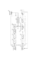
図1は本発明の実施例に係わる撮像装置を示すシステム構成図である。図1において、10は撮像装置1の光学系であり、ズームレンズ11a、焦点調節レンズ11b、シャッタ12、補正レンズユニット11c、絞りユニット13などによって構成される。14は、光学系10の光軸を表す。21は光学像を電気信号に変換する撮像素子、22は撮像素子21のアナログ信号出力をデジタル信号に変換するA/D変換器である。24は撮像素子21、A/D変換器22、D/A変換器27にクロック信号や制御信号を供給するタイミング発生部であり、メモリ制御部25及びシステム制御部50により制御される。
FIG. 1 is a system configuration diagram showing an imaging apparatus according to an embodiment of the present invention. In FIG. 1,
23は画像処理部であり、A/D変換器22からのデータ或いはメモリ制御部25からのデータに対して所定の画素補間処理や色変換処理やガンマ処理を行う。また、画像処理部23では、撮像した画像データを用いて所定の処理を行い、得られた結果に基づいてシステム制御部50が露光制御部41、フォーカス制御部42に対して制御を行う。つまり、コントラスト方式のAF(オートフォーカス)処理、AE(自動露出)処理等を行う。さらに、画像処理部23では、撮像した画像データを用いて所定の演算処理を行い、得られた演算結果に基づいてAWB(オートホワイトバランス)処理も行うことも可能である。なお、露光制御部の具体的な演算処理については後に詳述する。
An image processing unit 23 performs predetermined pixel interpolation processing, color conversion processing, and gamma processing on the data from the A /
25はメモリ制御部であり、A/D変換器22、画像処理部23、タイミング発生部24、画像表示メモリ26、D/A変換器27、圧縮伸張部28、内部メモリ29を制御する。A/D変換器22のデータが画像処理部23、メモリ制御部25を介して、或いはA/D変換器22のデータが直接メモリ制御部25を介して、画像表示メモリ26或いは内部メモリ29に書き込まれる。26は画像表示メモリ、27はD/A変換器である。7はTFT,LCD等から成る画像表示部であり、画像表示メモリ26に書き込まれた表示用の画像データはD/A変換器27を介して画像表示部7により表示される。画像表示部7を用いて撮像した画像データを逐次表示すれば、電子ファインダ機能を実現することが可能である。また、画像表示部7には画像が表示されるだけでなく、画像表示と共に、もしくは画像を表示することなく、撮像装置1の各種設定に関する様々なメニュー項目も表示する。ユーザは画像表示部7に表示されたメニュー項目を、操作スイッチ5を操作しながら適宜選択することにより、指定した項目の設定を変更することができる。
A memory control unit 25 controls the A /
28は適応離散コサイン変換(ADCT)等により画像データを圧縮伸長する圧縮伸長部であり、内部メモリ29に格納された画像を読み込んで圧縮処理或いは伸長処理を行い、処理を終えたデータを内部メモリ29に書き込む。29は撮影した静止画像や動画像を格納するための内部メモリであり、所定枚数の静止画像や所定時間の動画像を格納するのに十分な記憶量を備えている。これにより、複数枚の静止画像を連続して撮影する連写撮影やパノラマ撮影の場合にも、高速かつ大量の画像書き込みを内部メモリ29に対して行うことが可能となる。また、内部メモリ29はシステム制御部50の作業領域としても使用することが可能である。
A compression / decompression unit 28 compresses and decompresses image data by adaptive discrete cosine transform (ADCT) or the like, reads an image stored in the internal memory 29, performs compression processing or decompression processing, and stores the processed data in the internal memory. Write to 29. Reference numeral 29 denotes an internal memory for storing captured still images and moving images, and has a sufficient storage capacity for storing a predetermined number of still images and a predetermined time of moving images. As a result, even in the case of continuous shooting or panoramic shooting in which a plurality of still images are continuously shot, it is possible to write a large amount of images to the internal memory 29 at high speed. The internal memory 29 can also be used as a work area for the
30は補正レンズユニット制御部であり、通常の撮影時には、振れ検出器33によってカメラの振れ量を検出し、その振れ量に応じて、駆動制御部31、位置検出センサ32によって補正レンズユニット11cを制御し、カメラ振れによる像振れを抑える。振れ検出器33は例えばジャイロセンサを用いて構成されており、位置検出センサ32は例えばホール素子を用いて構成されている。被写体像に存在する輝点を用いて図形を描画するときには、更に不揮発性メモリ46に記録されている軌跡データを処理した上で補正レンズユニット11cを制御する。具体的な処理については後に詳述する。
41はシャッタ12や絞りユニット13を制御する露光制御部であり、ストロボ制御部8を介して制御されるストロボ9と連携することにより、ストロボ撮影にも対応する。42は焦点調節レンズ11bを制御するフォーカス制御部であり、43はズームレンズ11aによってズーミングを制御するズーム制御部であり、44はレンズの前面に配置される保護部材であるバリア2の動作を制御するバリア制御部である。
Reference numeral 41 denotes an exposure control unit that controls the
9はストロボであり、ストロボ制御部8によって制御されることにより、AF補助光の投光機能、ストロボ調光機能にも対応する。50は撮像装置1全体を制御するシステム制御部であり、45はシステム制御部50の動作用の定数、変数、プログラム等を一時的に記憶する揮発性メモリである。
46は電気的に消去・記録可能な不揮発性メモリであり、例えばEEPROM等が用いられる。撮像装置1の動作時に必要な定数、変数、プログラム等を、撮像装置1の非動作時にも失われないように記録している。撮像装置1の動作時には、システム制御部50の呼び出し指示に応じて記録されている定数、変数、プログラム等をシステム制御部50に送る。システム制御部は必要に応じて、呼び出した定数、変数、プログラム等を、適宜利用できるようにメモリ45に展開する。また、上述のように軌跡データも不揮発性メモリ46に記録されている。具体的な記録態様や、利用の仕方については後に詳述する。
Reference numeral 46 denotes an electrically erasable / recordable nonvolatile memory such as an EEPROM. Constants, variables, programs, and the like necessary for the operation of the imaging apparatus 1 are recorded so that they are not lost even when the imaging apparatus 1 is not operating. During operation of the imaging apparatus 1, constants, variables, programs, and the like that are recorded in response to a call instruction from the
47はシステム制御部50でのプログラムの実行に応じて、文字、画像、音声等を用いて動作状態やメッセージ等を表示する液晶表示装置等の表示部である。この表示部47は撮像装置1の操作部近辺の視認し易い位置に単数或いは複数個所設置され、例えばLCDやLEDの組み合わせにより構成されている。また、表示部47は、その一部の機能が光学ファインダ6内に設置されていることもある。表示部47では、例えばシャッタスピードや絞り値、露出補正やストロボ発光の設定などを表示する。
Reference numeral 47 denotes a display unit such as a liquid crystal display device that displays an operation state, a message, and the like using characters, images, sounds, and the like in accordance with execution of a program in the
3,4および5はシステム制御部50の各種の動作指示を入力するための操作部であり、スイッチやダイアル、タッチパネル、音声認識装置等の単数或いは複数の組み合わせで構成される。
3はレリーズスイッチであり、具体的には2段階に押し込むことができるように構成されている。ユーザは、1段目までの押し込み操作である半押し操作(SW1のオン)で撮影準備指示を行い、2段目までの押し込み操作である全押し(SW2のオン)操作で撮影指示を行うことができる。撮影準備指示であるSW1のオンで、システム制御部50は、AF(オートフォーカス)処理や、AE(自動露出)処理などの撮影準備動作を行うように制御する。そして、撮影指示であるSW2のオンで、システム制御部50は、露光制御部41を介してシャッタ12や絞りユニット13を駆動して、被写体画像を撮像素子21により取り込む制御を行う。具体的には、撮像素子21を蓄積状態にして、シャッタ12を開閉駆動することで被写体像を露光する。このシャッタ12の開閉の間が露光時間、すなわちシャッタスピードとなる。シャッタ12が閉状態に戻って撮像素子21の電荷蓄積を終了した後に、蓄積された電荷を信号として読み出す。システム制御部50およびメモリ制御部25は、撮像素子21から読み出した信号を、A/D変換器22、画像処理部23、圧縮伸張部28および内部メモリ29を用いて一連の現像処理や画像処理を行って画像データを生成する。そして、生成された画像データは、撮像装置1側のインターフェース51とコネクタ52、および着脱可能である記録媒体60側のコネクタ61とインタフェース62を介して、記録媒体60の記録部63に画像ファイルとして記録される。記録部63としては、ハードディスクやフラッシュメモリなどの、複数枚の画像データを記録するのに十分な容量を有するものが適している。なお、53は撮像装置1に対して記録媒体60が装着されているか否かを検出する記録媒体着脱検出部である。
A
手振れ補正がオンに設定されているときには、補正レンズユニット制御部30がSW1のオンに合わせて補正レンズユニット11cを動作させて、撮像素子21上で結像される被写体像の、ユーザの手振れに起因して生じる振れを軽減する。
When the camera shake correction is set to ON, the correction lens
更に、軌跡描画モードに設定されているときには、補正レンズユニット制御部30は、SW2のオン後の露光時間に指定された図形を描くように、補正レンズユニット11cを駆動する。
Further, when the locus drawing mode is set, the correction lens
4はモードダイアルスイッチであり、電源オフ、撮影モード(通常の撮影モード、軌跡描画モード等)、再生モード、PC接続モード等の各機能モードを切り換えて設定することができる。5は各種ボタンやタッチパネル等からなる操作スイッチであり、メニューボタン、セットボタン、ストロボ設定ボタン等が設けられている。
手振れ補正のオンもしくはオフの設定をするためには、手振れ補正設定のために設けられた、例えばスライドスイッチから成る操作スイッチ5を操作する。
In order to turn on or off camera shake correction, an
また、軌跡描画機能をオンにする場合には、モードダイヤル4を軌跡描画モードに切り換えた後、画像表示部7に表示される描画メニューを、例えば十字キーから成る操作スイッチ5により選択して設定する。具体的な表示等については後述する。
When the locus drawing function is turned on, after the
6は光学ファインダであり、直接的に被写体を確認することが可能である。この場合、画像表示部7による電子ファインダ機能を使用すること無しに、光学ファインダ6のみを用いて撮影を行える。また、光学ファインダ6内には表示部47の一部を配設して、例えば、シャッタスピードや絞り値などを確認できるようにしても良い。
48は電源制御部であり、電池検出回路、DC/DCコンバータ、通電するブロックを切り換えるスイッチ回路等により構成されている。そして、電池の装着の有無、電池の種類、電池残量の検出を行い検出結果をシステム制御部50に送る。また、システム制御部50の指示に基づいて、必要な電力を適宜撮像装置1の各部へ供給する。
A power control unit 48 includes a battery detection circuit, a DC / DC converter, a switch circuit that switches a block to be energized, and the like. Then, the presence / absence of a battery, the type of battery, and the remaining battery level are detected, and the detection result is sent to the
70は供給電源であり、コネクタ71と撮像装置1側のコネクタ49を介して、電源部72の電力を撮像装置1側に供給する。電源部72は、アルカリ電池やリチウム電池等の一次電池、またはNiCd電池やNiMH電池やLi電池等の二次電池、ACアダプター等のいずれか、もしくはこれらの組合わせにより構成される。
A
54は通信制御部であり、USBやIEEE1394、LAN、無線通信等の各種通信機能をサポートする。55は、通信部54により撮像装置1を他の機器と接続するためのコネクタ、あるいは無線通信をするためのアンテナである。 A communication control unit 54 supports various communication functions such as USB, IEEE 1394, LAN, and wireless communication. Reference numeral 55 denotes a connector for connecting the imaging device 1 to another device by the communication unit 54 or an antenna for wireless communication.
次に図2から図4を用いて軌跡描画モードおよび軌跡描画機能について説明する。 Next, the locus drawing mode and the locus drawing function will be described with reference to FIGS.
軌跡描画モードは、夕暮れ時や夜間など背景が暗いシーンの中に遠くの街灯などの点光源(輝点)が存在する場合に、撮像素子21の露光時間中に補正レンズユニット11cを駆動して、その点光源で予定した軌跡(輝線)を描くモードである。 In the locus drawing mode, when a point light source (bright spot) such as a distant street lamp exists in a scene with a dark background such as dusk or at night, the correction lens unit 11c is driven during the exposure time of the image sensor 21. In this mode, a locus (bright line) planned with the point light source is drawn.
図2は、通常の撮影モード設定時(軌跡描画機能オフ)と、軌跡描画モード設定時(軌跡描画機能オン)とで得られる画像を比較する概略図である。 FIG. 2 is a schematic diagram comparing images obtained when the normal shooting mode is set (trajectory drawing function off) and when the trajectory drawing mode is set (trajectory drawing function on).
図2(a)は、通常の撮影モード設定で撮影したときに得られる画像の例である。主たる被写体である人物が撮像装置1から比較的近い位置におり、その背景は夜景であって街灯などによる点光源がいくつか存在する。この画像の例は、少なくとも露光時には手振れ補正を行いつつ、露光中のあるタイミングでストロボ9を発光させて人物を照射したものである。このように撮影すると、ストロボ9の照射範囲内に存在する人物は、ストロボ光が反射して明るく写り、ストロボ9の照射範囲外の遠景は、自ら発光する点光源(ここでは街灯)のみが撮像素子21まで到達して写ることになる。ただし、遠景の街灯は撮像装置1に対して照度としては小さいので、いわゆるスローシャッタでなければ被写体像として写らない。そのためここでは手振れ補正をオンにして、点光源が点として写るようにしている。
FIG. 2A shows an example of an image obtained when shooting is performed with normal shooting mode settings. A person who is a main subject is located relatively close to the imaging device 1, the background is a night view, and there are several point light sources such as street lamps. In this example of the image, a person is irradiated by causing the
図2(b)は、図2(a)と同じ構図で、軌跡描画モード設定で撮影したときに得られる画像の例を表している。ここでは、ユーザが予め星型を描画図形として選択していたものとする。撮像素子が露光の状態にある期間、すなわち露光中において、手振れ補正の目標値に星型を描画するための目標値を重畳して補正レンズユニット11cを駆動すると、背景の点光源は撮像素子21上で星型を描いて写ることになる。一方、人物はストロボ9により照射される。ストロボ9の発光時間は撮像素子21の露光時間に対して十分に短く、また、人物はストロボ発光時以外は何ら照射光を受けることのない低照度下に存在しているので、ほぼストロボ光が反射した像だけが撮像素子21に届いて静止したように写る。すると図2(b)のように、1枚の画像に、点光源である街灯については星型を描いて写り、人物は静止して写るこということになる。
FIG. 2B shows an example of an image obtained with the same composition as that in FIG. Here, it is assumed that the user has previously selected a star shape as a drawing figure. When the correction lens unit 11c is driven by superimposing a target value for drawing a star shape on a target value for camera shake correction during a period in which the image sensor is in an exposure state, that is, during exposure, the background point light source becomes the image sensor 21. A star is drawn on the top. On the other hand, the person is illuminated by the
図2(b)では星型の例を示したが、予め定められた複数の図形やサイズから、ユーザの選択により任意の図形やサイズを選択することができる。 FIG. 2B shows an example of a star shape, but an arbitrary figure or size can be selected by a user's selection from a plurality of predetermined figures and sizes.
図3は、ユーザによる軌跡図形やサイズの選択等を説明するための図である。具体的には、モードダイヤル4で軌跡描画モードが選択されているときに、メニュー呼び出しのための操作スイッチ5が操作された場合に表示される画像表示部7のメニュー画面である。
FIG. 3 is a diagram for explaining selection of a locus graphic and a size by the user. Specifically, this is a menu screen of the image display unit 7 displayed when the
301は現在表示されているメニュー項目が、撮影に関する項目であることを示すためのアイコンタブである。この他に再生に関する項目であることを示すためのタブ302と、撮影/再生以外の設定項目であることを示すためのタブ303があり、これらは、操作スイッチ5の一部である十字キーのうち、左右キーの操作により移動および選択が可能である。
軌跡図形やサイズの選択については、撮影モードのひとつである軌跡描画モードに関する項目であるので、撮影に関するアイコンタブ301が選択されたときにメニュー項目として表示される。
The selection of the trajectory graphic and size is an item related to the trajectory drawing mode, which is one of the shooting modes, and is therefore displayed as a menu item when the
304から307は軌跡描画モードに関するメニュー項目である。それぞれのメニュー項目は、操作スイッチ5の一部である十字キーのうち、上下キーの操作により移動および選択が可能である。撮影に関するメニュー項目はこれら以外にも多数存在し、同様に上下キーを操作することで、メニュー項目はスクロールされて新たな項目が表示される。現在表示されているメニュー項目が、全体のメニュー項目に対してどのくらいの位置にあたるかを示すために、全体を示すためのバー308aと、バー308a上に重ねられた、位置を示すためのバー308bが表示されている。
304 to 307 are menu items related to the locus drawing mode. Each menu item can be moved and selected by operating the up and down keys of the cross key that is a part of the
304は、軌跡描画モードにおいて、同時に手振れ補正を行うか否かを選択するための、「手振れ補正」のメニュー項目である。手振れ補正設定のために別途設けられたスライドスイッチ(操作スイッチ5)で、手振れ補正がオフにされていたとしても、軌跡描画モードが選択されたときには自動的にオンにしたいときなどのために用意されている。これは、軌跡描画モードでは原則としてスローシャッタで撮影することが多いために、手持ち撮影では手振れが起きやすく、軌跡の描画とともに手振れ補正を行ったほうがきれいな図形が描けるからである。逆に、スライドスイッチでは手振れ補正がオンになっていても、撮像装置1を三脚に固定して軌跡描画をさせる場合には、むしろ手振れ補正機能が邪魔になることがある。このようなときには、予めこのメニュー項目で手振れ補正を「切」に選択しておけばよい。なお、図では「入」が選択されている様子を表している。
305は、軌跡描画モードで点光源を利用して描かせたい図形を選択するための、「図形選択」のメニュー項目である。図3においては、上下キーによりこの項目が選択されて太枠表示され、アクティブとなっている様子を示している。さらに、メニュー項目がハイライト表示された状態でセットボタン(操作スイッチ5)を操作すると、それぞれの図形が左右キーで選択できる状態になる。図3では、この選択できる状態を表している。また、それぞれの図形はアイコンで表示されている。現在選択されている図形のアイコンは網掛けされた状態で表示され、図3では星型が選択されていることを示す。また、ここに表示された星型、ハート型、丸型以外にも選択可能な図形が用意されている。左向きの三角アイコンはさらに左側に隠れて選択可能な図形が存在することを表し、同様に、右向きの三角アイコンはさらに右側に隠れて選択可能な図形が存在することを表している。隠れて選択可能な図形としては、例えば、ダイヤやスペードがあっても良い。ユーザは左右キーを操作することで網掛け部を移動させ、所望の図形を選択することができる。
306は、図形選択で選択した図形を、どれくらいの大きさで撮影画像中に描かせたいかを選択するための、「図形サイズ」のメニュー項目である。図3の例では「小」、「中」、「大」が選択できるようになっており、ここでは「中」が選択されている様子を示している。
307は、図形選択で選択した図形の、どの点を描画の開始点とするかを選択するための、「描画始点」のメニュー項目である。例えば、「図形選択」で丸型が選択されたときに、補正レンズユニット11cを、「下」→「上」→「下」と一周させるのか、「上」→「下」→「上」と一周させるかによって、描かれる丸とストロボ照射される被写体との相対的な位置関係が変わってくる。従って、描画の開始点をユーザの意図によって選択できるようにしている。ここでは「上」、「下」、「右」、「左」が選択可能なように用意されており、図では「下」が選択されている様子を表している。なお、出力される画像と、撮像素子21上に結像される被写体像とでは、上下左右が逆の関係になるので、メニューにおける「上」、「下」、「右」、「左」は、補正レンズユニット11cの始動位置としては「下」、「上」、「左」、「右」に対応することになる。また、選択される図形によっては、「上」、「下」、「右」、「左」に対応する位置が明確ではない場合があるが、これは後に説明する軌跡データに予めどの位置が「上」、「下」、「右」、「左」に対応するかが定義付けられている。
図3では、モードダイヤル4で軌跡描画モードが選択されているときに呼び出されるメニュー画面について説明したが、これ以外のモードが選択されているときには、304から307のメニュー項目はグレーアウトされ、選択ができないようにされる。
In FIG. 3, the menu screen called when the mode drawing mode is selected with the
次に、描画始点の設定について図4を用いて更に説明する。 Next, the setting of the drawing start point will be further described with reference to FIG.
図4は、描画始点の違いにより、撮影画像としてどのような差が生じるかを説明する図である。 FIG. 4 is a diagram for explaining what kind of difference occurs as a captured image due to a difference in drawing start point.
図4(a)において、中央の点は背景の輝点を示している。そして、撮像装置1の近くに手をかざして、背景の輝点との位置関係が図4(a)の関係になるように構図を決めて撮影する場合について述べる。低照度下でかざされた手はストロボ9の照射範囲内に存在する。なお、ここでは描画する図形として、「図形選択」メニューで「ハート型」が選択されているものとする。
In FIG. 4A, the center point indicates the bright spot of the background. Then, a case will be described in which a hand is held near the imaging apparatus 1 and the composition is determined so that the positional relationship with the bright spot in the background becomes the relationship shown in FIG. A hand held under low illuminance is within the irradiation range of the
図4(b)は、描画始点として「下」が選択されているときに得られる画像を表すものである。描画始点を「下」にすると、ハート型の最下点から描画が開始されるため、図4(a)での輝点の位置よりも上側に輝線の描画が行われることになる。従って、描画されるハートは、あたかもかざされた手に乗ったように写し込まれる。 FIG. 4B shows an image obtained when “lower” is selected as the drawing start point. When the drawing start point is set to “below”, drawing starts from the heart-shaped lowest point, so that a bright line is drawn above the position of the bright point in FIG. Therefore, the drawn heart is copied as if it were on a hand held up.
一方、描画始点として「上」が選択されているときには、図4(c)のような撮影画像が得られる。描画始点を「上」にすると、ハート型の上部の一点から描画を開始するため、ハート型は図4(a)での輝点の位置よりも下側に輝線の描画が行われることになる。従って、かざされた手とハート型が重なった画像となる。 On the other hand, when “upper” is selected as the drawing start point, a captured image as shown in FIG. 4C is obtained. When the drawing start point is set to “above”, drawing starts from one point at the top of the heart shape, so that the heart shape draws a bright line below the position of the bright point in FIG. . Therefore, an image in which the hand held over the heart shape overlaps.
次に、不揮発性メモリ46に記録されている軌跡データについて、図5を用いて説明する。図5は、軌跡データの記録形式を概念的に説明するための図である。軌跡データは、メニュー画面でユーザによって選択された設定に従って、補正レンズユニット11cを駆動させるためのデータである。システム制御部50が不揮発性メモリ46から、ユーザによって選択された図形の軌跡データを読み出し、その他の図形サイズや描画始点といった設定項目や、露出情報などと共に駆動制御部31に送る。駆動制御部を構成する軌跡制御部31g(後述)は、これらの情報を受け取り、描画を行うために必要な補正レンズユニット11cの移動量を演算する。
Next, the trajectory data recorded in the nonvolatile memory 46 will be described with reference to FIG. FIG. 5 is a diagram for conceptually explaining the recording format of the trajectory data. The locus data is data for driving the correction lens unit 11c in accordance with the setting selected by the user on the menu screen. The
図5(a)は、軌跡データの格納ルールを示す図である。ある図形を示す軌跡データは配列構造を持ち、先頭アドレスにはその軌跡データがいずれの図形を示すデータであるのかを示す「図形情報」が格納されている。従ってシステム制御部50は、ユーザによって選択された図形をこの図形情報と照合し、一致するものを読み出す。
FIG. 5A is a diagram illustrating a storage rule for trajectory data. The trajectory data indicating a certain graphic has an array structure, and “graphic information” indicating which graphic the trajectory data indicates is stored in the head address. Therefore, the
そして次に「描画始点アドレス」が格納されている。これは、ユーザに選択された描画始点が「上」、「下」、「右」、「左」のいずれかによって、どの座標データから使用するかを示すものである。 Next, the “drawing start point address” is stored. This indicates from which coordinate data the drawing start point selected by the user is used depending on which of “upper”, “lower”, “right”, and “left”.
「描画始点アドレス」の次には「描画軌跡長」が格納されている。これはその図形の軌跡の長さに相当する。すなわち選択された図形を描き終わるまでに、補正レンズユニット11cをどれだけ動かさなければならないかがこの情報から演算される。したがって、この「描画軌跡長」に基づいて、その図形を描くのに要する時間、すなわち最適な露光時間を決定することができる。 Next to the “drawing start point address”, “drawing trajectory length” is stored. This corresponds to the length of the trace of the figure. That is, how much the correction lens unit 11c has to be moved before drawing the selected figure is calculated from this information. Therefore, based on this “drawing trajectory length”, the time required to draw the figure, that is, the optimum exposure time can be determined.
露光時間よりも軌跡描画時間(図形を描くために補正レンズユニット11cを動かす必要がある時間)の方が短ければ、図形を描き終わった後も露光状態が続くことになるので、その図形の終端部分で滲み(高輝度の部分)を生じることになる。また、選択された図形を一回りして描き終わっても留まることなくさらに二回り目、三回り目をした場合に、開始点と終了点が一致していないときに露光時間が終了すると、一つの図形内に輝度の高い軌跡部分と、低い軌跡部分を生じさせることになる。 If the trajectory drawing time (the time required to move the correction lens unit 11c to draw the figure) is shorter than the exposure time, the exposure state will continue after drawing the figure, so the end of the figure Bleeding (high-brightness part) occurs in the part. In addition, if the second and third turns are made without stopping even if the selected figure is drawn once, the exposure time ends when the start point and end point do not match. A locus portion with high brightness and a locus portion with low brightness are generated in one figure.
逆に、露光時間の方が軌跡描画時間よりも短ければ、その図形を描ききる前に露光時間が終了することになるので、途中で途切れた未完成の図形が撮影画像として表れることになる。 On the other hand, if the exposure time is shorter than the trajectory drawing time, the exposure time ends before the figure is completely drawn, so that an incomplete figure interrupted in the middle appears as a photographed image.
従って、露光時間は、選択された図形を一回りして描く時間、もしくは整数回まわって描く時間である軌跡描画時間と一致することが好ましい。具体的な露光時間の算出と露出条件の決定に関しては、後に詳述する。 Therefore, it is preferable that the exposure time coincides with the trajectory drawing time which is the time for drawing the selected figure once or drawing it for an integer number of times. Specific calculation of exposure time and determination of exposure conditions will be described in detail later.
「描画軌跡長」の次からは、必要な数だけ座標値が格納されている。座標値は座標1、座標2、座標3…と続き、補正レンズユニット11cは、順番にこれらに対応する位置に駆動されることで、選択された図形をトレースすることになる。矢印は補正レンズユニット11cが次に移動される位置に対応する座標を概念的に示すものである。描画開始時には、描画始点アドレスに従って矢印がセットされる。その後は順次インクリメントされて(矢印が次の座標アドレスへセットされて)座標値が読み出される。 The necessary number of coordinate values are stored after the “drawing trajectory length”. The coordinate values are coordinate 1, coordinate 2, coordinate 3,..., And the correction lens unit 11c is sequentially driven to positions corresponding to these to trace the selected figure. The arrows conceptually indicate the coordinates corresponding to the position where the correction lens unit 11c is moved next. At the start of drawing, an arrow is set according to the drawing start point address. Thereafter, the coordinate values are read out by sequentially incrementing (an arrow is set to the next coordinate address).
なお、この軌跡データはメニュー項目「図形サイズ」で選択される「中」を基準に作成されている。従って、「図形サイズ」で「中」が選択されている場合には、軌跡データに記述された座標値に従って補正レンズユニット11cの目標値を設定すればよい。 The trajectory data is created based on “medium” selected by the menu item “graphic size”. Therefore, when “medium” is selected as the “graphic size”, the target value of the correction lens unit 11c may be set according to the coordinate value described in the trajectory data.
「大」が選択されている場合には、描画軌跡長を2倍に換算して露光時間等を算出し、更に、補正レンズユニット11cの移動に関しては、矢印が示す座標値を2倍に換算する。座標値を読み出すサンプリング周期を、補正レンズユニット11cを駆動するサンプリング周期の1/2倍(読み出す時間の間隔を駆動する時間の間隔の2倍)とし、座標値を読み出さないタイミングの座標値は前後の座標値の中間値とする。つまり、補正レンズユニット11cを駆動するサンプリングについては、2回に1回座標値を読み出すサンプリングに同期し、このときは軌跡データから2倍に換算した座標値が目標値に用いられる。そして、同期していないときには前後の換算座標値の中間値(補間座標)が目標値に用いられることになる。このようにすることで、補正レンズユニット11cは、座標(0,0)を基準とした2倍の大きさの軌跡を、同じ駆動速度で、2倍の時間をかけて移動することができる。 When “Large” is selected, the drawing trajectory length is converted to double to calculate the exposure time and the like, and the movement of the correction lens unit 11c is converted to double the coordinate value indicated by the arrow. To do. The sampling period for reading the coordinate value is set to ½ times the sampling period for driving the correction lens unit 11c (the reading time interval is twice the driving time interval). The intermediate value of the coordinate value of. In other words, the sampling for driving the correction lens unit 11c is synchronized with the sampling for reading the coordinate value once every two times, and at this time, the coordinate value converted to twice from the trajectory data is used as the target value. When not synchronized, the intermediate value (interpolated coordinate) of the previous and subsequent converted coordinate values is used as the target value. In this way, the correction lens unit 11c can move a trajectory that is twice as large as the reference with respect to the coordinates (0, 0) at the same driving speed and takes twice as much time.
「小」が選択されている場合には、「大」が選択されている場合の逆の関係になる。つまり、描画軌跡長を1/2倍に換算して露光時間等を算出し、更に、補正レンズユニット11cの移動に関しては、矢印が示す座標値を1/2倍に換算する。座標値を読み出すサンプリング周期を、補正レンズユニット11cを駆動するサンプリング周期の2倍(読み出す時間の間隔を駆動する時間の間隔の1/2倍)とし、補正レンズユニット11cを駆動しないタイミングの座標値は利用せずに無視するものとする。つまり、座標値を読み出すサンプリングについては、2回に1回補正レンズユニット11cを駆動するサンプリングと同期するが、このときは軌跡データから1/2倍に換算した座標値が目標値として用いられ、同期していないときには用いられないことになる。(もちろん、目標値として用いられないタイミングでは、読み出しを行わないように構成しても良い。)このようにすることで、補正レンズユニット11cは、座標(0,0)を基準とした1/2倍の大きさの軌跡を、同じ駆動速度で、1/2倍の時間で移動することができる。 When “small” is selected, the reverse relationship is obtained when “large” is selected. That is, the exposure time and the like are calculated by converting the drawing trajectory length to ½ times, and the coordinate value indicated by the arrow is converted to ½ times for the movement of the correction lens unit 11c. The sampling period for reading the coordinate value is set to twice the sampling period for driving the correction lens unit 11c (the reading time interval is ½ times the driving time interval), and the coordinate value at the timing when the correction lens unit 11c is not driven. Shall be ignored without being used. That is, the sampling for reading the coordinate value is synchronized with the sampling for driving the correction lens unit 11c once every two times, but at this time, the coordinate value converted to 1/2 times from the trajectory data is used as the target value. It is not used when not synchronized. (Of course, the reading may not be performed at a timing that is not used as the target value.) By doing so, the correction lens unit 11c is 1/2 with respect to the coordinates (0, 0). A trajectory that is twice as large can be moved in half the time at the same drive speed.
なお、ここでは基準として格納されている軌跡データをサイズ「中」とし、2倍、1/2倍のサイズに関する例を示したが、線形補間的にこの方法を適用すれば2倍、1/2倍以外の倍率であっても設定することができる。また、基準として格納されてる軌跡データとしては、最小のサイズに対応する座標データを持っていても、逆に最大のサイズに対応する座標データを持っていても良い。 In this example, the trajectory data stored as the reference is the size “medium”, and an example relating to the size of 2 times or 1/2 times has been shown. However, if this method is applied in a linear interpolation manner, the size is 2 times, 1 / It can be set even at a magnification other than two times. The trajectory data stored as a reference may have coordinate data corresponding to the minimum size, or conversely, coordinate data corresponding to the maximum size.
図5(b)および図5(c)は、軌跡データの格納ルールを具体的な図形に適用した場合を示す図であり、図5(b)は星型を、図5(c)はハート型を示す図である。それぞれ記述されている値は図5(a)に対応する。例えば図5(b)においては、「図形情報」として先頭アドレスに「星型」が、「描画始点アドレス」として、「上」が選択されたときには「座標1」から読み出し、「下」が選択されたときには「座標20」から読み出すといった情報が記述されている。「描画軌跡長」として「100」が、「座標1」、「座標2」…として、「0、−10」、「2、−13」…が記述されている。「描画始点」のメニュー項目で「上」が選択されている場合には、描画始点アドレスとして「上:座標1」が指示されているので、初期値として矢印を座標1にセットされる。そして、「図形サイズ」として「中」が選択されていれば、座標1から最後の座標まで順に矢印がインクリメントされてセットされ、補正レンズユニット11cを駆動するためのデータとして用いられる。「描画始点」のメニュー項目で「下」が選択されている場合には、描画始点アドレスとして「下:座標20」が指示されているので、初期値として矢印を座標20(不図示)にセットされる。そして、座標20から最後の座標まで順に矢印がインクリメントされてセットされ、さらに座標1にジャンプして座標19まで同様にインクリメントされて、補正レンズユニット11cを駆動するためのデータとして用いられる。選択された図形を2回り、3回りして描く場合には、これを2回、3回と繰り返せばよい。また、「図形サイズ」として「大」または「小」が選択されているときは、前述のルールに従って読み出される。 5 (b) and 5 (c) are diagrams showing a case where the storage rule of trajectory data is applied to a specific figure, FIG. 5 (b) is a star shape, and FIG. 5 (c) is a heart shape. It is a figure which shows a type | mold. The values described respectively correspond to FIG. For example, in FIG. 5B, “star shape” is selected as the “graphic information” at the start address, and “upper” is selected as the “drawing start point address”. In such a case, information such as reading from “coordinate 20” is described. “100” is described as “drawing trajectory length”, and “0, −10”, “2, −13”... Are described as “coordinate 1”, “coordinate 2”. When “Up” is selected in the “Drawing start point” menu item, since “Up: Coordinate 1” is designated as the drawing start point address, an arrow is set at the coordinate 1 as an initial value. If “middle” is selected as the “graphic size”, the arrows are sequentially incremented from the coordinate 1 to the last coordinate, and are used as data for driving the correction lens unit 11c. When “down” is selected in the “drawing start point” menu item, “down: coordinate 20” is designated as the drawing start point address, so an arrow is set at the coordinate 20 (not shown) as an initial value. Is done. Then, the arrow is incremented and set in order from the coordinate 20 to the last coordinate, and further jumps to the coordinate 1 and is similarly incremented to the coordinate 19 to be used as data for driving the correction lens unit 11c. If the selected figure is drawn twice or three times, this may be repeated twice or three times. When “large” or “small” is selected as the “graphic size”, it is read according to the rules described above.
「描画開始アドレス」は、例えば丸型のように「上」、「下」、「右」、「左」の位置が幾何学的に明確である場合には、その座標値を対応させて定義付ければよい。しかし、星型や、ハート型については、例えば「右」や「左」は図形の重心に対して必ずしも明確な特徴点を有しない。このような場合は、比較的近くに存在する特徴点である頂点や変極点、または左右方向に最大値、最小値をとるような点を定義付けすればよい。これは、描画軌跡を開始する点として、ユーザが感覚的に認識しやすいからである。 “Drawing start address” is defined by correlating the coordinate values when the positions of “top”, “bottom”, “right”, and “left” are geometrically clear, such as a round shape. You can attach it. However, for the star shape and the heart shape, for example, “right” and “left” do not necessarily have a clear feature point with respect to the center of gravity of the figure. In such a case, vertices and inflection points that are relatively close feature points, or points that have maximum and minimum values in the left-right direction may be defined. This is because it is easy for the user to perceive sensuously as a point to start the drawing trajectory.
次に、図6を用いて駆動制御部31の内部構成とこれに関連する構成について説明する。図6はこれらの構成をブロック図を用いて示す図である。
Next, an internal configuration of the
まず、モードダイヤル4が軌跡描画モード以外の撮影モードに設定され、スライドスイッチ(操作スイッチ5)で手振れ補正がオンとされている場合について説明する。
First, a case where the
振れ検出器33によって検出された信号は、フィルタ31aやアンプ31bによって必要な信号のみ抽出され、A/D変換器31cによってアナログ値からデジタル値に変換される。そして、演算器31dで積分処理されることにより、ユーザの手振れ量に応じた、補正レンズユニット11cを駆動するための第1の移動目標量が演算され、そのまま駆動目標位置演算部31iに入力される。 From the signal detected by the shake detector 33, only necessary signals are extracted by the filter 31a and the amplifier 31b, and are converted from analog values to digital values by the A / D converter 31c. Then, the integration process is performed by the calculator 31d, whereby the first movement target amount for driving the correction lens unit 11c corresponding to the amount of camera shake of the user is calculated and input as it is to the drive target position calculation unit 31i. The
補正レンズユニット11cの位置検出センサ32によって検出された信号は、アンプ31eにて増幅され、A/D変換器31fを介して補正レンズユニット11cの位置信号として駆動目標位置演算部31iに入力される。 The signal detected by the position detection sensor 32 of the correction lens unit 11c is amplified by the amplifier 31e, and input to the drive target position calculation unit 31i as the position signal of the correction lens unit 11c via the A / D converter 31f. .
駆動目標位置演算部31iは、これら入力される信号を用いて、フィードバック制御を行う。駆動目標位置演算部31iでは、システム制御部50より入力されるズームレンズ11aの位置情報を用いて算出される敏感度等を考慮して、補正レンズユニット11cの移動目標位置を算出する。そして算出された移動目標位置に従って、駆動ドライバ31jは補正レンズユニット11cのコイルに通電し、補正レンズ(後述の補正レンズ800)を光軸と直交する平面内で移動させて目標位置に到達するように駆動する。
The drive target position calculation unit 31i performs feedback control using these input signals. The drive target position calculation unit 31i calculates the movement target position of the correction lens unit 11c in consideration of sensitivity and the like calculated using the position information of the zoom lens 11a input from the
これら一連の動作を高速かつ周期的に繰り返すことにより、ユーザの手振れによって撮像装置1が振れても、撮像素子21上で結像する被写体像はほぼ静止した状態を保つことができ、手振れの影響の軽減された撮影画像を得ることが可能となる。 By repeating these series of operations at high speed and periodically, even if the imaging apparatus 1 is shaken by a user's camera shake, the subject image formed on the image sensor 21 can be kept almost stationary, and the influence of camera shake. It is possible to obtain a photographic image with reduced image quality.
次に、モードダイヤル4が軌跡描画モードに設定され、「手振れ補正」のメニュー項目304で、手振れ補正が「入」とされている場合について説明する。
Next, the case where the
振れ検出器33で検出された信号が入力されて、演算器31dで第1の移動目標量が演算されるまでは、上記の通常の手振れ補正の信号処理と同様である。 The processing is the same as that in the normal camera shake correction signal processing until the signal detected by the shake detector 33 is input and the first moving target amount is calculated by the calculator 31d.
軌跡描画モードで図形を描くときには、上述の軌跡データがシステム制御部50より軌跡制御部31gに入力される。同時にシステム制御部からは、ユーザによって設定された描画サイズと描画始点の情報が入力され、軌跡制御部31gは、上述のように描画始点のアドレスのセットや、描画サイズに応じた拡大/縮小の演算を行う。そして、補正レンズユニット11cを駆動する周期で、描画のための移動目標量としての第2の移動目標量を演算/生成する。
When drawing a figure in the locus drawing mode, the locus data described above is input from the
描画を行うための駆動を開始するタイミングは、シャッタが開いたタイミングに同期する。具体的には、露光制御部41からのタイミング信号が、システム制御部50を介して、軌跡制御部31gに入力されることにより、同期が実現される。
The timing to start driving for drawing is synchronized with the timing at which the shutter is opened. Specifically, the synchronization is realized by the timing signal from the exposure control unit 41 being input to the trajectory control unit 31g via the
演算器31dより出力されるユーザの手振れ量に応じた移動量である第1の移動目標量と、軌跡制御部31gより出力される描画のための移動量である第2の移動目標量は、加算器31hで加算された後、駆動目標位置演算部31iに入力される。駆動目標位置演算部31iでは、入力された第1の移動目標量と第2の移動目標量の合算量と、A/D変換器31fより入力された補正レンズユニット11cの現在位置から、補正レンズユニット11cの移動目標位置を算出する。そして算出された移動目標位置に従って、駆動ドライバ31jは補正レンズユニット11cのコイルに通電し、補正レンズ(後述の補正レンズ800)を光軸と直交する平面内で移動させて目標位置に到達するように駆動する。
A first movement target amount that is a movement amount according to the amount of user shake output from the computing unit 31d and a second movement target amount that is a movement amount for drawing output from the trajectory control unit 31g are: After being added by the
これら一連の動作を撮像素子21の露光時間中に行うことにより、ユーザの手振れの影響を軽減しつつ、選択された図形を設定に従って描画することが可能となる。 By performing these series of operations during the exposure time of the image sensor 21, it is possible to draw the selected figure according to the setting while reducing the influence of the user's hand shake.
次に、モードダイヤル4が軌跡描画モードに設定され、「手振れ補正」のメニュー項目304で、手振れ補正が「切」とされている場合について説明する。
Next, the case where the
この場合は、システム制御部50の指示により演算器31dの出力が0とされ、振れ検出器からの影響を除去する。従って、駆動目標位置演算部31iへの入力は第2の移動目標量のみとなる。駆動目標位置演算部31iでは、入力された第2の移動目標量と、A/D変換器31fより入力された補正レンズユニット11cの現在位置から、補正レンズユニット11cの移動目標位置を算出する。そして算出された移動目標位置に従って、駆動ドライバ31jは補正レンズユニット11cのコイルに通電し、補正レンズ(後述の補正レンズ800)を光軸と直交する平面内で移動させて目標位置に到達するように駆動する。
In this case, the output of the computing unit 31d is set to 0 by the instruction of the
これら一連の動作を撮像素子21の露光時間中に行うことにより、選択された図形を設定に従って描画することが可能となる。このように制御を行うことは、複雑な図形や大きなサイズの図形を描かせる場合であって、露光時間が長くなるような場合に、三脚で撮像装置1を固定して撮影する状況下で有効である。 By performing these series of operations during the exposure time of the image sensor 21, it becomes possible to draw the selected figure according to the setting. Such control is effective in the case where a complicated figure or a large-size figure is drawn and the exposure time is long, and the imaging device 1 is fixed with a tripod and is photographed. It is.
上記の説明においては、光軸14に対して垂直な面内で移動する補正レンズユニット11cの、平面内の2軸分の駆動をまとめて説明しているが、2軸で移動させるためには各軸方向のそれぞれに上記各要素を有するものとする。
In the above description, driving of the correction lens unit 11c that moves in a plane perpendicular to the
図7は、図6を用いて説明した、モードダイヤル4が軌跡描画モードに設定され、「手振れ補正」のメニュー項目304で、手振れ補正が「入」とされている場合における、補正レンズユニット11cの動作を概略的に説明するための図である。横軸は撮像素子21の露光開始からの時間の経過を表し、縦軸は光軸中心からの移動量を表す。なお、補正レンズユニット11cは、光軸14に対して垂直な面内で移動するので、2軸の方向を有するが、ここでは簡単のため、1軸方向の動作について説明する。
FIG. 7 illustrates the correction lens unit 11c described with reference to FIG. 6 when the
図7(a)は、被写体像が撮像素子21上で振れることなく、光軸14を中心として結像するように、ユーザの手振れに応答して、補正レンズユニット11cを駆動した場合を表す図である。すなわち、通常の手振れ補正制御による駆動であり、第1の移動目標量のみに基づいて駆動ドライバ31jを制御したときの状態を示したものである。
FIG. 7A illustrates a case where the correction lens unit 11c is driven in response to a user's camera shake so that the subject image is focused on the
図7(b)は、軌跡制御部31gが出力する第2の移動目標量のみに基づいて駆動ドライバ31jを制御したときの状態を示した図である。すなわち、補正レンズユニット11cは、軌跡データに基づいて軌跡制御部31gが出力する軌跡を描くこととなる。 FIG. 7B is a diagram illustrating a state when the drive driver 31j is controlled based only on the second movement target amount output from the trajectory control unit 31g. That is, the correction lens unit 11c draws a locus output from the locus control unit 31g based on the locus data.
なお、ここでは説明のため軌跡データは、
x軸方向に
x=αsin(ωt) …(1)
x軸と直交するy軸方向に、
y=αcos(ωt)−α …(2)
となるように、量子化されて座標値に換算されて与えられ、
露光時間は、
0≦t≦2π/ω …(3)
となるように与えられているものとする。すなわち、補正レンズユニット11cが、露光時間中に、(0,0)を始点として、(0、−α)を中心する半径αの円軌跡を1周描くように軌跡データと露光時間が与えられているものとする。したがって、図7(b)は、このx軸の軌跡データに従って補正レンズユニット11cを駆動した場合の、x軸方向の移動量を表す図である。
For the sake of explanation here, the trajectory data is
x = αsin (ωt) in the x-axis direction (1)
In the y-axis direction orthogonal to the x-axis,
y = αcos (ωt) −α (2)
So that it is quantized and converted into coordinate values,
Exposure time is
0 ≦ t ≦ 2π / ω (3)
Is given to be That is, during the exposure time, the correction lens unit 11c is given the locus data and the exposure time so as to draw one round of the circular locus with the radius α centered at (0, −α), starting from (0, 0). It shall be. Accordingly, FIG. 7B is a diagram showing the amount of movement in the x-axis direction when the correction lens unit 11c is driven according to the x-axis trajectory data.
図7(c)は、図7(a)で示した第1の移動目標量、および図7(b)で示した第2の移動目標量を足し合わせた移動目標量に基づいて、駆動ドライバ31jを制御した場合を示した図である。 FIG. 7C shows a driving driver based on the movement target amount obtained by adding the first movement target amount shown in FIG. 7A and the second movement target amount shown in FIG. It is the figure which showed the case where 31j was controlled.
図7(c)に示す補正レンズユニット11cの移動を行うことで、手振れは第1の移動目標量の効果により補正され、かつ、第2の移動目標量に従って撮像素子21上で設定された図形を描くことが可能となる。 By moving the correction lens unit 11c shown in FIG. 7C, the camera shake is corrected by the effect of the first movement target amount, and the figure set on the image sensor 21 according to the second movement target amount Can be drawn.
次に、補正レンズユニット11cの駆動機構について図8を用いて説明する。図8は、補正レンズユニット11cの補正レンズ800を移動させる機構を概略的に示す図である。
Next, the drive mechanism of the correction lens unit 11c will be described with reference to FIG. FIG. 8 is a diagram schematically showing a mechanism for moving the
図8(a)において、801はレンズを保持する可動枠、800は補正レンズ、803は鏡筒に取り付けられた固定部、804は可動枠上の支持/案内部、805は支持/案内部と同軸に取り付けられたバネを示す。また、806a、806bは固定部に取り付けられたコイル、807a、807bは可動枠に取り付けられたマグネットを示す。図8(b)は図8(a)に示した手振れ補正機構の右側面図である。図8(b)において、810、812は図8(a)には図示しないヨークである。811は図8(a)には図示しない可動部の位置を検出するセンサである。具体的には、位置検出センサ32を構成する要素であり、センサとしてはホール素子が用いられている。図8(c)は図8(a)の802矢視図である。可動枠801は支持/案内部804によって固定部803に対して平面運動可能に案内支持されている。図8(c)では、長円形の案内溝813の中に円形の支持/案内部804が挿入されている。手振れ補正機構は、3箇所とも同一の構造とすることによって、撮像光学系10の光軸14の方向には拘束され、光軸14に直行する平面上では運動させることができる。可動枠801上には、手振れ補正レンズ800及び駆動用のマグネット807a、807bが取り付けられている。また、可動枠801は支持/案内部804と同軸に取り付けられたバネ805によって弾性支持されており、駆動力が発生していないときは手振れ補正レンズ800の中心が光軸14に略一致するように配置されている。駆動部分は図8(b)に示すようにマグネット807aの両側をヨークで挟み込み、片側にコイル806aを備えた構成をしている。駆動部分の原理は図9を用いて説明する。
8A,
図9(a)、(b)は、図8(a)に示す点線808を断面として駆動回路部分を抜粋した矢視図である。駆動用マグネット807aは2極で厚み方向に着磁されている。更に、マグネット807aの着磁方向の両側にはヨーク810、812が設けられており、多くの磁束は外に漏れることなく、図9(a)の図中に示すような矢印方向の磁界を発生させている。この状態でコイル806aに通電すると、コイル806a上の領域901と902には、それぞれ反対方向の電流が流れる。一方、磁界の方向も反対であるため、フレミング左手の法則によって同一方向の力が発生する。このときコイルが固定されているため、作用反作用の法則によって可動部に取り付けられたマグネット807aが力を受けて駆動される。駆動力はコイル806aの電流に比例し、コイル806aに流す電流の向きを反対方向にすることによって、マグネット807aが受ける駆動力も反対にすることができる。駆動力が発生すると、可動部がバネ805によって弾性支持されているので、バネ力と釣り合う点まで変位する。つまり、コイル806aの電流を適切に制御することによって、可動部の位置を制御することができる。
FIGS. 9A and 9B are arrow views extracted from the drive circuit portion with the dotted
更に、ヨーク810上にはホール素子811が取り付けられており、図9(b)に示すように、コイル806aに電流を印加することにより発生した駆動力によってマグネット807aが変位すると、ホール素子811上の磁気バランスも変化する。そのため、ホール素子811の信号を得ることによって、マグネット807aの位置を検出することが可能となる。
Further, a
図8、図9では、可動部にマグネットが配置され、固定部にコイルが配置されたムービングマグネット方式での実施形態を例示した。しかしながら、本実施例は、可動部にコイルが配置され、固定部にマグネットが配置されたムービングコイルについても適用可能である。 8 and 9 exemplify an embodiment using a moving magnet system in which a magnet is arranged in the movable part and a coil is arranged in the fixed part. However, this embodiment can also be applied to a moving coil in which a coil is arranged in the movable part and a magnet is arranged in the fixed part.
次に、本実施例に係る撮像動作について図10を用いて説明する。図10は本実施例における撮像動作のフローチャートである。なお、図3を用いて説明したメニュー画面等により、種々の動作の実行/不実行が予めユーザの設定によって決定されているものとする。 Next, an imaging operation according to the present embodiment will be described with reference to FIG. FIG. 10 is a flowchart of the imaging operation in the present embodiment. It should be noted that execution / non-execution of various operations is determined in advance by user settings on the menu screen described with reference to FIG.
ステップS1001において、モードダイヤル4で軌跡描画モードが設定されているか否かを確認する。軌跡描画モードでないときは通常の撮影モードが設定されている(軌跡描画機能オフ)ものとして、ステップS1002へ進む。
In step S1001, it is confirmed whether or not the locus drawing mode is set with the
ここではまず、通常の撮影モードが設定されている場合について説明する。 Here, a case where the normal shooting mode is set will be described first.
ステップS1002はレリーズスイッチ3のSW1の入力待機状態である。ステップS1002でSW1がオンされると、ステップS1003において、システム制御部50はスライドスイッチ(操作スイッチ5)により手振れ補正がオンに設定されているかを確認する。手振れ補正がオンに設定されていれば、ステップS1004で手振れを補正するための補正レンズユニット11cの駆動を開始する。すなわち図7(a)を用いて説明した通常の手振れ補正制御による駆動を開始する。
Step S1002 is an input standby state of SW1 of the
ステップS1004で手振れを補正するための補正レンズユニット11cの駆動を開始した後、もしくはステップS1003で手振れ補正がオフに設定されていると判断された場合には補正レンズユニット11cを駆動することなく、ステップS1005に進む。 After driving the correction lens unit 11c for correcting camera shake in step S1004 or when it is determined in step S1003 that camera shake correction is set to OFF, the correction lens unit 11c is not driven. The process proceeds to step S1005.
ステップS1005では、システム制御部50およびフォーカス制御部42で焦点調節レンズ11bを制御することにより、AF(オートフォーカス)を実行する。具体的には、焦点調節レンズ11bを微小量駆動させつつ連続的に取り込んだ被写体画像のコントラストをシステム制御部50で検出し、コントラストが最も高くなる位置を合焦位置とする公知のコントラスト方式を用いる。
In step S1005, the
次にステップS1006では、システム制御部50がAE(自動露出)処理を行う。具体的には、オートフォーカス実行時に得られる被写体画像を用いて、メインになると想定される被写体、例えば画面中央付近の被写体が適正露出となるように、シャッタスピード、絞り値および撮像素子21の出力ゲインであるISO感度を演算し決定する。
In step S1006, the
このAE処理は被写体の測光と、露出演算の2段階からなる。被写体の測光としては、オートフォーカス実行時に得られる1枚の被写体画像を複数の領域に分割し、それぞれの輝度値に重み付け等の処理をして平均輝度値を算出することにより行われる。露出演算では、測光結果である平均輝度値と目標輝度値の差分を演算し、この演算結果に基づいて、シャッタスピード、絞り値およびISO感度を決定する。 This AE process consists of two steps: subject photometry and exposure calculation. Metering of a subject is performed by dividing one subject image obtained at the time of execution of autofocus into a plurality of areas, and performing processing such as weighting on each luminance value to calculate an average luminance value. In the exposure calculation, the difference between the average luminance value, which is a photometric result, and the target luminance value is calculated, and the shutter speed, aperture value, and ISO sensitivity are determined based on the calculation result.
撮影モードとしては、全自動モード、絞り優先モード、シャッタスピード優先モードが用意されている。全自動モードは、システム制御部50がシャッタスピード、絞り値およびISO感度を任意に決定する。具体的には、予め不揮発性メモリ46に用意されたプログラム線図に則って決定する。このプログラム線図は、例えば被写体輝度が小さい(暗い)場合には、できるだけ手振れを起こさないシャッタスピードと、開放に近い絞り値および高いISO感度となるように考慮されている。絞り優先モードの場合には、ユーザが指定した絞り値を維持するように、プログラム線図に則ってシャッタスピードとISO感度を調整する。シャッタスピード優先モードの場合には、ユーザが指定したシャッタスピードを維持するように、プログラム線図に則って被写体輝度に合わせて絞り値とISO感度を調整する。
As shooting modes, a fully automatic mode, an aperture priority mode, and a shutter speed priority mode are prepared. In the fully automatic mode, the
ステップS1006でAE処理を行った後、ステップS1007では、レリーズスイッチ3のSW2の入力を待つ。ステップS1002のSW1オンから所定時間内にSW2がオンされない場合には、再度ステップS1002まで戻り、SW1オンの入力待機状態となる。
After performing the AE process in step S1006, in step S1007, the input of SW2 of the
ステップS1007でSW2がオンされると、ステップS1008で、システム制御部50はストロボ制御部8を介してストロボ9の調光発光を行う。なお、ステップS1006のAE処理で被写体輝度が十分大きい(明るい)と判断されれば、ストロボを発光させる必要がないが、ここでは説明のため被写体輝度が小さくストロボを発光させる必要がある場合について説明する。
When SW2 is turned on in step S1007, the
ステップS1009では、ステップS1008で調光発光を行った結果を受け、システム制御部50は、その反射量から本発光量を演算する。具体的には、本発光をさせたときに撮像素子21で飽和画素が生じないように(白飛びしないように)調整される。
In step S1009, in response to the result of the dimming light emission in step S1008, the
ステップS1010では、露光制御部41がシステム制御部50の指示を受けて、撮像素子21が露光状態となるように、シャッタ12を開き、絞りユニット13を定められた絞り値に従って絞り込むことにより、露光を開始する。
In step S1010, the exposure control unit 41 receives an instruction from the
そして、ステップS1011では、所定のタイミングで、ステップS1009で演算された本発光量に従って、ストロボ制御部8がストロボ9を発光する。
In step S1011, the
次に、ステップS1006で定められたシャッタスピードに応じた露光時間が経過したら、ステップS1012で、露光制御部41はシャッタ12を閉じ、絞りを開放状態に戻す。撮像素子21の露光が終了すると、ステップS1013では、図1を用いて説明したように画像処理を行い、ステップS1014では、処理された画像ファイルを記録媒体60へ記録し、かつ画像表示部7へ処理された画像データを表示する。以上で通常の撮影モードによる一連の撮影動作を終了する。
Next, when the exposure time corresponding to the shutter speed determined in step S1006 has elapsed, in step S1012, the exposure control unit 41 closes the
次に、ステップS1001において、モードダイヤル4で軌跡描画モードが設定されていると判断した場合について説明する。
Next, a case where it is determined in step S1001 that the locus drawing mode is set with the
軌跡描画モード(軌跡描画機能オン)であるときは、ステップS1015へ進む。 If it is in the locus drawing mode (the locus drawing function is on), the process proceeds to step S1015.
ステップS1015は、ステップS1002と同様に、レリーズスイッチ3のSW1の入力待機状態である。ステップS1015でSW1がオンされると、ステップS1016において、システム制御部50は手振れ補正のメニュー項目304で、手振れ補正を行うように設定されているかを確認する。ここでは、ステップS1003と異なり、図3を用いて説明したように、スライドスイッチ(操作スイッチ5)による手振れ補正の設定に関わらず、メニュー項目304による設定に従う。
Step S1015 is an input standby state of SW1 of the
手振れ補正がオンに設定されていれば、ステップS1017で手振れを補正するための補正レンズユニット11cの駆動を開始する。すなわち図7(a)を用いて説明した通常の手振れ補正制御による駆動を開始する。 If camera shake correction is set to ON, driving of the correction lens unit 11c for correcting camera shake is started in step S1017. That is, the driving by the normal camera shake correction control described with reference to FIG.
ステップS1017で手振れを補正するための補正レンズユニット11cの駆動を開始した後、もしくはステップS1016で手振れ補正がオフに設定されていると判断された場合には補正レンズユニット11cを駆動することなく、ステップS1018に進む。 After driving the correction lens unit 11c for correcting camera shake in step S1017 or when it is determined in step S1016 that camera shake correction is set to OFF, the correction lens unit 11c is not driven. The process proceeds to step S1018.
ステップS1018では、ステップS1005と同様に、システム制御部50およびフォーカス制御部42で焦点調節レンズ11bを制御することにより、AF(オートフォーカス)を実行する。
In step S1018, as in step S1005, the
ステップS1018でAFを実行すると、次にAE処理を行う。ここで、軌跡描画モードでは、このAE処理に本実施例の特徴が表れるので、被写体の測光と、露出演算の2段階をそれぞれ分けて説明することにする。 If AF is executed in step S1018, AE processing is next performed. Here, in the trajectory drawing mode, the characteristics of the present embodiment appear in this AE process. Therefore, the two steps of subject photometry and exposure calculation will be described separately.
ステップS1019では、被写体の測光を行う。被写体の測光は、ステップS1006で説明した測光と同様に、オートフォーカス実行時に得られる1枚の被写体画像を複数の領域に分割し、それぞれの輝度値に重み付け等の処理をして平均輝度値を算出することにより行われる。次に露出演算を行うが、測光結果である平均輝度値と目標輝度値の差分を演算し、この演算結果に基づいて、シャッタスピード、絞り値およびISO感度を決定するという原則はステップS1006のAE処理と同様である。ただし、決定の仕方が撮影モードとして用意されている、全自動モード、絞り優先モード、シャッタスピード優先モードのそれぞれで異なる。 In step S1019, subject photometry is performed. Similar to the photometry described in step S1006, the subject photometry is performed by dividing one subject image obtained at the time of execution of autofocus into a plurality of areas and performing processing such as weighting on each luminance value to obtain an average luminance value. This is done by calculating. Next, the exposure calculation is performed. The principle of calculating the difference between the average luminance value, which is a photometric result, and the target luminance value, and determining the shutter speed, aperture value, and ISO sensitivity based on the calculation result is the AE in step S1006. It is the same as the processing. However, the determination method is different for each of the fully automatic mode, aperture priority mode, and shutter speed priority mode, which are prepared as shooting modes.
ステップS1019で被写体の測光が行われたら、次にステップS1020で、システム制御部50は、現在の撮影モードが全自動モードであるか否かを判断する。全自動モードであると判断されると、ステップS1021で、システム制御部50は、図形選択のメニュー項目である305で選択されている図形に対応する軌跡データを不揮発性メモリ46から読み出し、その軌跡データの中から描画軌跡長を取得する。
If subject photometry is performed in step S1019, then in step S1020, the
描画軌跡長を取得すると、次にステップS1022ではまず、シャッタスピードを決定する。具体的には、まずステップS1021で取得した描画軌跡長を図形サイズのメニュー項目である306で選択されているサイズに応じて変換する。「大」が選択されていれば2倍に換算し、「中」が選択されていればそのままとし、「小」が選択されていれば1/2倍に換算する。そして、例えば描画をさせようとする輝点の輝度に応じて決定される周回回数(選択された図形を露光時間中に何周させて描くか)を更に掛けて、補正レンズ800の移動距離を決定する。この移動距離を予め定められている補正レンズ800が駆動される速度で除することにより、選択された図形を選択されたサイズで描くための時間を求める。この時間がシャッタスピードとして定められる。
When the drawing trajectory length is acquired, in step S1022, first, the shutter speed is determined. Specifically, first, the drawing trajectory length acquired in step S1021 is converted according to the size selected in the graphic
このようにシャッタスピードが決定されると、ユーザが選択した図形を、途中で途切れることなく、また、滲みやムラを生じることなく描くことができる。 When the shutter speed is determined in this way, the figure selected by the user can be drawn without being interrupted and without causing blurring or unevenness.
シャッタスピードが決定されると、このシャッタスピードと、ステップS1019で得られた測光演算結果に基づいて、メインになると想定される被写体、例えば画面中央付近の被写体が適正露出となるように絞り値とISO感度が決定される。 When the shutter speed is determined, based on the shutter speed and the photometric calculation result obtained in step S1019, the aperture value is set so that the subject that is assumed to be the main, for example, the subject near the center of the screen has a proper exposure. ISO sensitivity is determined.
ここで、ステップS1022で軌跡描画モードとして基準となる適正露出は、ステップS1006で通常の撮影モードとして基準となる適正露出に対して、例えば1段程度アンダーに設定される。これは、次の理由による。 Here, the appropriate exposure that becomes the reference as the locus drawing mode in step S1022 is set, for example, about one step under the appropriate exposure that becomes the reference as the normal shooting mode in step S1006. This is due to the following reason.
軌跡描画モードが想定するシーンの一つとして図2で示したように、背景に点光源が存在し、ストロボ9の照射範囲内に人物が存在する場合に、人物はストロボ発光時以外は照射光をほとんど受けない。しかしながら、人物が完全に照射光を受けない状況は現実的には少なく、実際は何らかの照明下に存在することが多い。軌跡描画モードではシャッタスピードが長く(長秒時に)なることが多いので、人物にわずかでも光があたっていると、補正レンズユニット11cの駆動により、さらには被写体である人物の揺れにより、人物の部分が全体的にブレや滲みのある画像となってしまう。ここで、例えば1段絞り込んだりISO感度を落とすことにより、このブレや滲みを相対的に暗くすることができる。一方、ストロボの発光量は調光発光により適切に設定され、かつ照射時間は極めて短時間であるので、ストロボ光により照射された期間の像は、適正な明るさであって、ブレや滲みを生じない像となることが期待できる。
As shown in FIG. 2 as one of the scenes assumed in the locus drawing mode, when a point light source exists in the background and a person exists within the irradiation range of the
具体的には、システム制御部50は、通常の撮影モードで、1/8秒、F2.0、ISO400が適正露出と判断される場合は、同一シーンで軌跡描画モードのときは、1/8秒、F4.0、ISO400、もしくは1/8秒、F2.0、ISO200を適正露出と判断する。なお、アンダーにする段数は1段に限られるものではなく、1/2段や1/3段などの段数でもよい。また、ステップS1019での被写体測光時に、人物と思われる被写体(画角中央付近の被写体)の輝度を測っておいて、システム制御部がこの輝度に応じてアンダーにする段数を変化させるように構成してもよい。
Specifically, the
ステップS1020で、現在の撮影モードが全自動モードでないと判断されると、システム制御部50は、ステップS1023で、現在の撮影モードが絞り優先モードであるか否かを判断する。絞り優先モードであると判断されると、ステップS1024で、システム制御部50は、図形選択のメニュー項目である305で選択されている図形に対応する軌跡データを不揮発性メモリ46から読み出し、その軌跡データの中から描画軌跡長を取得する。
If it is determined in step S1020 that the current shooting mode is not the fully automatic mode, the
描画軌跡長を取得すると、次にステップS1025では、すでに絞り値はユーザによって指定されているので、ここではシャッタスピードとISO感度を決定する。このとき、まずシャッタスピードを決定する。ステップS1022と同様に、具体的には、ステップS1024で取得した描画軌跡長を図形サイズのメニュー項目である306で選択されているサイズに応じて変換する。「大」が選択されていれば2倍に換算し、「中」が選択されていればそのままとし、「小」が選択されていれば1/2倍に換算する。そして、例えば描画をさせようとする輝点の輝度に応じて決定される周回回数(選択された図形を露光時間中に何周させて描くか)を更に掛けて、補正レンズ800の移動距離を決定する。この移動距離を予め定められている補正レンズ800が駆動される速度で除することにより、選択された図形を選択されたサイズで描くための時間を求める。この時間がシャッタスピードとして定められる。
When the drawing trajectory length is acquired, in step S1025, since the aperture value has already been specified by the user, the shutter speed and ISO sensitivity are determined here. At this time, the shutter speed is first determined. As in step S1022, specifically, the drawing trajectory length acquired in step S1024 is converted according to the size selected in 306, which is a menu item for graphic size. If “large” is selected, it is converted to double, if “medium” is selected, it is left as it is, and if “small” is selected, it is converted to 1/2. Then, for example, the number of rotations determined according to the brightness of the bright spot to be drawn (how many times the selected figure is drawn during the exposure time) is further multiplied to determine the movement distance of the
このようにシャッタスピードが決定されると、ユーザが選択した図形を、途中で途切れることなく、また、滲みやムラを生じることなく描くことができる。 When the shutter speed is determined in this way, the figure selected by the user can be drawn without being interrupted and without causing blurring or unevenness.
シャッタスピードが決定されると、このシャッタスピードと、指示された絞り値と、ステップS1019で得られた測光演算結果に基づいて、メインになると想定される被写体、例えば画面中央付近の被写体が適正露出となるようにISO感度が決定される。 When the shutter speed is determined, based on the shutter speed, the instructed aperture value, and the photometric calculation result obtained in step S1019, the subject that is assumed to be the main subject, for example, the subject near the center of the screen is appropriately exposed. ISO sensitivity is determined so that
ここで、ステップS1025で軌跡描画モードとして基準となる適正露出は、ステップS1022と同様に、ステップS1006で通常の撮影モードとして基準となる適正露出に対して、例えば1段程度アンダーに設定される。 Here, as in step S1022, the appropriate exposure that becomes the reference as the locus drawing mode in step S1025 is set to, for example, about one step under the appropriate exposure that becomes the reference in the normal shooting mode in step S1022.
具体的には、システム制御部50は、通常の撮影モードで、1/8秒、F4.0、ISO400が適正露出と判断される場合は、軌跡描画モードのとき、絞り値F4.0が指定されシャッタスピードが1/8秒と決定されると、ISO200が適正露出と判断される。
Specifically, the
ステップS1023で、現在の撮影モードが絞り優先モードでないと判断されると、システム制御部50は、現在の撮影モードをシャッタスピード優先モードと判断する。シャッタスピード優先モードでは、ユーザがシャッタスピードを指示している。したがって、ステップS1021やステップS1024のように軌跡データの中から描画軌跡長を取得することはしない。この場合は、ユーザが指定したシャッタスピードと、選択された図形を選択されたサイズで描く時間とが一致しないことがあり、途中で途切れたり重複して描かれることになるが、ユーザが指定したシャッタスピードに従うものとする。
If it is determined in step S1023 that the current shooting mode is not the aperture priority mode, the
ステップS1026では、ステップS1019で得られた測光演算結果に基づいて、メインになると想定される被写体、例えば画面中央付近の被写体が適正露出となるように絞り値とISO感度が決定される。ここで、ステップS1026で軌跡描画モードとして基準となる適正露出は、ステップS1022と同様に、ステップS1006で通常の撮影モードとして基準となる適正露出に対して、例えば1段程度アンダーに設定される。 In step S1026, based on the photometric calculation result obtained in step S1019, the aperture value and ISO sensitivity are determined so that the subject that is assumed to be the main subject, for example, the subject near the center of the screen has a proper exposure. Here, in step S1026, the appropriate exposure serving as the reference as the trajectory drawing mode is set to be, for example, about one step lower than the proper exposure serving as the reference as the normal shooting mode in step S1006, as in step S1022.
ステップS1022、ステップS1025もしくはステップS1026を経て、シャッタスピード、絞り値およびISO感度が決定されると、ステップS1027では、レリーズスイッチ3のSW2の入力を待つ。ステップS1015のSW1オンから所定時間内にSW2がオンされない場合には、再度ステップS1015まで戻り、SW1オンの入力待機状態となる。
When the shutter speed, aperture value, and ISO sensitivity are determined through step S1022, step S1025, or step S1026, in step S1027, input of SW2 of the
ステップS1027でSW2がオンされると、ステップS1028で、システム制御部50はストロボ制御部8を介してストロボ9の調光発光を行う。
When SW2 is turned on in step S1027, the
ステップS1029では、ステップS1028で調光発光を行った結果を受け、システム制御部50は、その反射量から本発光量を演算する。具体的には、本発光をさせたときに撮像素子21で飽和画素が生じないように(白飛びしないように)調整される。
In step S1029, the
ステップS1030では、露光制御部41がシステム制御部50の指示を受けて、撮像素子21が露光状態となるように、シャッタ12を開き、絞りユニット13を定められた絞り値に従って絞り込むことにより、露光を開始する。
In step S1030, the exposure control unit 41 receives an instruction from the
撮像素子の露光と同時にステップS1031では、駆動制御部31がシステム制御部50から必要な情報を受け取って、補正レンズユニット11cを動作させて、軌跡駆動を開始する。具体的には、駆動制御部31は、システム制御部からユーザによって選択された図形の軌跡データを受け取り、同じくユーザによって選択されたサイズを受け取って、軌跡データの座標値を上述のように変換する。そして、軌跡データから描画始点アドレスを取得し、ユーザによって選択された描画始点に対応する座標値から描画が開始されるようにセットする。駆動制御部31は、ステップS1017で手振れ補正駆動を開始している場合は、すでに補正レンズユニット11cを動作させている(図7(a)に相当する動作)。この場合、ステップS1031では、ステップS1030の露光開始と共に、描画始点としてセットされた座標値に応じた第2の移動目標量を、ユーザの手振れ量に応じた第1の移動目標量に加算することで、補正レンズユニット11cの移動目標量とする。駆動制御部31は、この移動目標量に従って補正レンズユニット11cを駆動する。これを、軌跡データに従って順次座標値をインクリメントし、サンプリング周期に同期して移動目標量を更新していくことにより、ユーザの手振れを補正しつつ、選択された図形を選択されたサイズで描くことが可能になる(図7(c)に相当する動作)。
Simultaneously with exposure of the image sensor, in step S1031 , the
そして、ステップS1032では、所定のタイミングで、ステップS1029で演算された本発光量に従って、ストロボ制御部8がストロボ9を発光する。
In step S1032, the
ストロボ本発光後、ステップS1033で図形の描画が完了し、駆動制御部31は描画のための軌跡駆動を終了する。これと同時にステップS1034で露光制御部41はシャッタ12を閉じ、絞りを開放状態に戻す。ただし、全自動モードおよび絞り優先モードでは選択された図形を適切に描けるようにシャッタスピードが設定されているが、シャッタスピード優先モードにおいては、図形の描画完了と露光の終了とが一致するとは限らない。シャッタスピード優先モードでは、場合によっては描画が完了する前に駆動制御部31は描画のための軌跡駆動を終了する。
After the main flash emission, the drawing of the figure is completed in step S1033, and the
撮像素子21の露光が終了すると、ステップS1035では、図1を用いて説明したように画像処理を行う。ただし、ここで適用される入力輝度値に対する出力輝度値を規定するγ曲線は、ステップS1013において通常の撮影モードで適用されるγ曲線と異なる。 When the exposure of the image sensor 21 is completed, in step S1035, image processing is performed as described with reference to FIG. However, the γ curve that defines the output luminance value with respect to the input luminance value applied here is different from the γ curve applied in the normal shooting mode in step S1013.
軌跡描画モードにおけるγ補正について説明する。上述のように、軌跡描画モードが想定するシーンの一つとして図2で示したように、背景に点光源が存在し、ストロボ9の照射範囲内に人物が存在する場合に、人物はストロボ発光時以外は照射光をほとんど受けない。しかしながら、人物が完全に照射光を受けない状況は現実的には少なく、実際は何らかの照明下に存在することが多い。軌跡描画モードではシャッタスピードが長く(長秒時に)なることが多いので、人物にわずかでも光があたっていると、補正レンズユニット11cの駆動により、さらには被写体である人物の揺れにより、人物の部分が全体的にブレや滲みのある画像となってしまう。すると、点光源によって描いた輝線が、このブレや滲みと重畳してしまい、鮮明にならない場合がある。そこで、軌跡描画モードでは、輝度の高い輝線と、薄暗く表れるブレや滲みとの間でコントラストを明確にするために、通常の撮影モードにおけるγ補正とは異なるγ補正を施す。具体的には、低輝度の被写体は相対的に目立たなくし、高輝度の被写体は強調されるようなγ曲線を用いたγ補正を行う。
The γ correction in the locus drawing mode will be described. As described above, as shown in FIG. 2 as one of the scenes assumed by the trajectory drawing mode, when a point light source exists in the background and a person exists within the irradiation range of the
図11(a)は、通常の撮影モードで適用されるγ曲線の一例を示す図であり、図11(b)は、軌跡描画モードで適用されるγ曲線の一例を示す図である。通常の撮影モードに比べ、軌跡描画モードでは輝線を鮮明にするために、低輝度側の入力信号に対する出力信号を十分に下げ、高輝度側の入力信号に対する出力信号を相対的に上げている。このように変化させることで、低輝度側の被写体に対して高輝度側の被写体が強調され、画像全体としてコントラストが高くなる。 FIG. 11A is a diagram illustrating an example of the γ curve applied in the normal photographing mode, and FIG. 11B is a diagram illustrating an example of the γ curve applied in the locus drawing mode. Compared to the normal imaging mode, in the locus drawing mode, in order to make the bright line clear, the output signal for the low luminance side input signal is sufficiently lowered and the output signal for the high luminance side input signal is relatively increased. By changing in this way, the high-luminance subject is emphasized with respect to the low-luminance subject, and the contrast of the entire image is increased.
図10に戻り、ステップS1034で画像処理が終わると、ステップS1014に進み、ステップS1014では、処理された画像ファイルを記録媒体60へ記録し、かつ画像表示部7へ処理された画像データを表示する。以上で軌跡描画モードによる一連の撮影動作を終了する。 Returning to FIG. 10, when the image processing is completed in step S1034, the process proceeds to step S1014. In step S1014, the processed image file is recorded on the recording medium 60, and the processed image data is displayed on the image display unit 7. . This completes the series of shooting operations in the locus drawing mode.
上記の実施例においては、光学系10に補正レンズユニット11cを配置し、これを駆動することにより、撮像素子21上で結像される被写体像について、ユーザの手振れに起因して生じる振れを軽減すると共に、露光時間に指定された図形を描くように制御した。
In the above-described embodiment, the correction lens unit 11c is arranged in the
しかし、ユーザの手振れに起因して生じる振れを軽減すると共に、露光時間に指定された図形を描く構成は、これに限られるものではない。例えば、撮像素子21が光軸14に対して直交する方向に2次元的にシフト移動するように構成しても、同様の作用を得ることができる。具体的には、撮像素子21が2軸方向に摺動するように2本のガイドバーを設け、撮像素子側にコイル、固定側にマグネットを配置して、その反発力を利用して位置制御を行えば良い。
However, the configuration for reducing the shake caused by the hand shake of the user and drawing the figure designated for the exposure time is not limited to this. For example, even if the image pickup device 21 is configured to shift two-dimensionally in a direction orthogonal to the
1 撮像装置
11c 補正レンズユニット
21 撮像素子
31 駆動制御部
33 振れ検出器
41 露光制御部
50 システム制御部
DESCRIPTION OF SYMBOLS 1 Imaging device 11c Correction lens unit 21
Claims (7)
複数の図形から一つを選択する選択手段と、
前記撮像素子に結像される被写体像と前記撮像素子とを相対的に移動させるための移動手段と、
前記選択手段によって選択された図形の軌跡に従って前記移動手段を移動させて撮影を行う際に、前記軌跡の長さに複数周回回数を乗じた前記移動手段の移動距離に基づいて前記撮像素子の露光時間を決定する露光時間決定手段と、
前記露光時間決定手段によって決定された露光時間に従って、前記撮像素子を露光するとともに、該撮像素子の露光と同時に、前記選択手段によって選択された図形の軌跡に従って、前記移動手段を制御して前記撮像素子に結像される被写体像と前記撮像素子とを相対的に移動を開始し、前記移動手段が露光中に停止することがないように移動させる制御手段とを有する撮像装置。 An image sensor that photoelectrically converts a subject image formed by the imaging optical system;
A selection means for selecting one from a plurality of figures;
Moving means for relatively moving the subject image formed on the image sensor and the image sensor;
When imaging is performed by moving the moving means according to the locus of the graphic selected by the selecting means, the image sensor is exposed based on the moving distance of the moving means obtained by multiplying the length of the locus by the number of laps. Exposure time determining means for determining the time;
The imaging device is exposed according to the exposure time determined by the exposure time determining unit, and simultaneously with the exposure of the imaging device, the moving unit is controlled according to the locus of the graphic selected by the selection unit to control the imaging. An image pickup apparatus comprising: a control unit configured to start relative movement between a subject image formed on an element and the image pickup device and move the moving unit so that the moving unit does not stop during exposure.
前記手振れ検出手段の出力に基づいて、前記手振れを打ち消すための前記移動手段の移動量を算出する算出手段とを更に有し、
前記制御手段は、前記選択手段によって選択された図形の軌跡データに、前記算出手段によって算出された移動量を重畳して、前記移動手段を移動させることを特徴とする請求項1に記載の撮像装置。 Camera shake detection means for detecting camera shake;
A calculation means for calculating a movement amount of the moving means for canceling the shake based on an output of the shake detection means;
2. The imaging according to claim 1, wherein the control unit moves the moving unit by superimposing a movement amount calculated by the calculating unit on trajectory data of a graphic selected by the selecting unit. apparatus.
前記ガンマ調整手段によって設定されるガンマ曲線は、前記選択手段によって選択された図形の軌跡データに従って前記移動手段を移動させることなく撮影を行う撮影モードにおけるガンマ曲線に対し、低輝度側の出力輝度値を下げるように設定されることを特徴とする請求項1ないし4のいずれか1項に記載の撮像装置。 In the processing of the photographed image, it further includes gamma adjustment means for adjusting the output luminance value with respect to the input luminance value,
The gamma curve set by the gamma adjustment means is an output luminance value on the low luminance side relative to the gamma curve in the shooting mode in which shooting is performed without moving the moving means according to the locus data of the graphic selected by the selection means. 5. The imaging device according to claim 1, wherein the imaging device is set so as to lower the value.
複数の図形から選ばれた一つの図形を受け付ける選択工程と、
前記選択工程にて選択された図形の軌跡に従って前記移動手段を移動させて撮影を行う際に、前記軌跡の長さに複数周回回数を乗じた前記移動手段の移動距離に基づいて前記撮像素子の露光時間を演算する露光時間決定工程と、
前記露光時間決定工程によって決定された露光時間に従って、前記撮像素子を露光するとともに、該撮像素子の露光と同時に、前記選択工程にて受け付けた図形の軌跡に従って、前記移動手段を制御して前記撮像素子に結像される被写体像と前記撮像素子とを相対的に移動を開始し、前記移動手段が露光中に停止することがないように移動させる制御工程とを有する撮像装置の制御方法。 Control of an imaging apparatus comprising: an imaging device that photoelectrically converts a subject image formed by an imaging optical system; and a moving unit that relatively moves the subject image formed on the imaging device and the imaging device. A method,
A selection process for accepting one figure selected from a plurality of figures;
When shooting is performed by moving the moving means according to the trajectory of the graphic selected in the selection step, the imaging element is based on the moving distance of the moving means obtained by multiplying the length of the trajectory by the number of laps . An exposure time determination step for calculating the exposure time;
The imaging device is exposed in accordance with the exposure time determined in the exposure time determining step, and simultaneously with the exposure of the imaging device, the moving means is controlled in accordance with the locus of the figure received in the selection step to perform the imaging. A control method for an image pickup apparatus, comprising: a control step of starting a relative movement between a subject image formed on an element and the image pickup element so that the moving means does not stop during exposure.
Priority Applications (1)
| Application Number | Priority Date | Filing Date | Title |
|---|---|---|---|
| JP2007065280A JP5013910B2 (en) | 2007-03-14 | 2007-03-14 | IMAGING DEVICE AND IMAGING DEVICE CONTROL METHOD |
Applications Claiming Priority (1)
| Application Number | Priority Date | Filing Date | Title |
|---|---|---|---|
| JP2007065280A JP5013910B2 (en) | 2007-03-14 | 2007-03-14 | IMAGING DEVICE AND IMAGING DEVICE CONTROL METHOD |
Publications (3)
| Publication Number | Publication Date |
|---|---|
| JP2008228059A JP2008228059A (en) | 2008-09-25 |
| JP2008228059A5 JP2008228059A5 (en) | 2010-04-08 |
| JP5013910B2 true JP5013910B2 (en) | 2012-08-29 |
Family
ID=39846110
Family Applications (1)
| Application Number | Title | Priority Date | Filing Date |
|---|---|---|---|
| JP2007065280A Expired - Fee Related JP5013910B2 (en) | 2007-03-14 | 2007-03-14 | IMAGING DEVICE AND IMAGING DEVICE CONTROL METHOD |
Country Status (1)
| Country | Link |
|---|---|
| JP (1) | JP5013910B2 (en) |
Families Citing this family (5)
| Publication number | Priority date | Publication date | Assignee | Title |
|---|---|---|---|---|
| JP5031430B2 (en) * | 2007-04-17 | 2012-09-19 | キヤノン株式会社 | IMAGING DEVICE AND IMAGING DEVICE CONTROL METHOD |
| JP5053695B2 (en) * | 2007-04-26 | 2012-10-17 | キヤノン株式会社 | IMAGING DEVICE AND IMAGING DEVICE CONTROL METHOD |
| JP5031433B2 (en) * | 2007-04-26 | 2012-09-19 | キヤノン株式会社 | IMAGING DEVICE AND IMAGING DEVICE CONTROL METHOD |
| JP2010096531A (en) * | 2008-10-14 | 2010-04-30 | Kenkoo:Kk | Exposure meter |
| KR101890305B1 (en) * | 2012-08-27 | 2018-08-21 | 삼성전자주식회사 | Photographing apparatus, method for controlling the same, and computer-readable recording medium |
Family Cites Families (12)
| Publication number | Priority date | Publication date | Assignee | Title |
|---|---|---|---|---|
| JP2748423B2 (en) * | 1988-08-24 | 1998-05-06 | キヤノン株式会社 | Shooting device with variable filter effect |
| JPH0350209U (en) * | 1989-09-13 | 1991-05-16 | ||
| JP3376012B2 (en) * | 1993-04-15 | 2003-02-10 | キヤノン株式会社 | camera |
| JP3789143B2 (en) * | 1993-12-10 | 2006-06-21 | 株式会社ニコン | Camera optical system drive device |
| JPH1164941A (en) * | 1997-08-15 | 1999-03-05 | Canon Inc | Camera |
| JP2003087645A (en) * | 2001-09-07 | 2003-03-20 | Olympus Optical Co Ltd | Digital camera |
| JP2003234955A (en) * | 2002-02-12 | 2003-08-22 | Nikon Corp | Image processing device, image processing program, and image processing method |
| JP4214010B2 (en) * | 2003-02-03 | 2009-01-28 | 辰巳電子工業株式会社 | Automatic photo creation device |
| JP2005086488A (en) * | 2003-09-09 | 2005-03-31 | Nikon Corp | Electronic still camera and image processing program |
| JP4522270B2 (en) * | 2005-01-19 | 2010-08-11 | キヤノン株式会社 | Imaging apparatus and control method thereof |
| JP2006154863A (en) * | 2006-03-01 | 2006-06-15 | Nikon Corp | Method for driving blur correction apparatus |
| JP4906577B2 (en) * | 2007-04-27 | 2012-03-28 | キヤノン株式会社 | Imaging apparatus, control method therefor, and program |
-
2007
- 2007-03-14 JP JP2007065280A patent/JP5013910B2/en not_active Expired - Fee Related
Also Published As
| Publication number | Publication date |
|---|---|
| JP2008228059A (en) | 2008-09-25 |
Similar Documents
| Publication | Publication Date | Title |
|---|---|---|
| KR101337458B1 (en) | Imaging device display control method and medium | |
| US20180262686A1 (en) | Shooting device, shooting method and shooting control method | |
| JP5013910B2 (en) | IMAGING DEVICE AND IMAGING DEVICE CONTROL METHOD | |
| JP4974753B2 (en) | Imaging apparatus, control method therefor, and program | |
| JP2010081038A (en) | Imaging device, its control method, and program | |
| JP6300569B2 (en) | Imaging apparatus and control method thereof | |
| JP2007003872A (en) | Mode dialing mechanism | |
| JP6953296B2 (en) | Imaging control device and its control method | |
| JP5914829B2 (en) | Imaging device | |
| JP4974755B2 (en) | Imaging apparatus, control method therefor, and program | |
| JP4906576B2 (en) | Imaging apparatus, control method therefor, and program | |
| JP4863496B2 (en) | Imaging apparatus, control method therefor, and program | |
| JP4906577B2 (en) | Imaging apparatus, control method therefor, and program | |
| JP4986698B2 (en) | Imaging apparatus, control method therefor, and program | |
| JP4863497B2 (en) | Imaging apparatus, control method therefor, and program | |
| JP5031430B2 (en) | IMAGING DEVICE AND IMAGING DEVICE CONTROL METHOD | |
| JP5031433B2 (en) | IMAGING DEVICE AND IMAGING DEVICE CONTROL METHOD | |
| JP2006270426A (en) | Imaging apparatus, its control method, and computer program | |
| JP5053695B2 (en) | IMAGING DEVICE AND IMAGING DEVICE CONTROL METHOD | |
| JP2005354606A (en) | Digital camera | |
| JP2009139423A (en) | Imaging apparatus and subject distance calculating method | |
| JP5270870B2 (en) | Imaging apparatus and control method thereof | |
| JP2005134532A (en) | Imaging apparatus, display control method and display control program | |
| JP2007208715A (en) | Imaging device | |
| JP2004023161A (en) | Digital camera |
Legal Events
| Date | Code | Title | Description |
|---|---|---|---|
| RD04 | Notification of resignation of power of attorney |
Free format text: JAPANESE INTERMEDIATE CODE: A7424 Effective date: 20100201 |
|
| A521 | Request for written amendment filed |
Free format text: JAPANESE INTERMEDIATE CODE: A523 Effective date: 20100223 |
|
| A621 | Written request for application examination |
Free format text: JAPANESE INTERMEDIATE CODE: A621 Effective date: 20100223 |
|
| RD01 | Notification of change of attorney |
Free format text: JAPANESE INTERMEDIATE CODE: A7421 Effective date: 20100630 |
|
| A977 | Report on retrieval |
Free format text: JAPANESE INTERMEDIATE CODE: A971007 Effective date: 20110728 |
|
| A131 | Notification of reasons for refusal |
Free format text: JAPANESE INTERMEDIATE CODE: A131 Effective date: 20110802 |
|
| A521 | Request for written amendment filed |
Free format text: JAPANESE INTERMEDIATE CODE: A523 Effective date: 20110929 |
|
| A131 | Notification of reasons for refusal |
Free format text: JAPANESE INTERMEDIATE CODE: A131 Effective date: 20120313 |
|
| A521 | Request for written amendment filed |
Free format text: JAPANESE INTERMEDIATE CODE: A523 Effective date: 20120427 |
|
| TRDD | Decision of grant or rejection written | ||
| A01 | Written decision to grant a patent or to grant a registration (utility model) |
Free format text: JAPANESE INTERMEDIATE CODE: A01 Effective date: 20120529 |
|
| A01 | Written decision to grant a patent or to grant a registration (utility model) |
Free format text: JAPANESE INTERMEDIATE CODE: A01 |
|
| A61 | First payment of annual fees (during grant procedure) |
Free format text: JAPANESE INTERMEDIATE CODE: A61 Effective date: 20120605 |
|
| FPAY | Renewal fee payment (event date is renewal date of database) |
Free format text: PAYMENT UNTIL: 20150615 Year of fee payment: 3 |
|
| FPAY | Renewal fee payment (event date is renewal date of database) |
Free format text: PAYMENT UNTIL: 20150615 Year of fee payment: 3 |
|
| LAPS | Cancellation because of no payment of annual fees |