JP5013169B2 - Vehicle seat belt control device - Google Patents
Vehicle seat belt control device Download PDFInfo
- Publication number
- JP5013169B2 JP5013169B2 JP2006251020A JP2006251020A JP5013169B2 JP 5013169 B2 JP5013169 B2 JP 5013169B2 JP 2006251020 A JP2006251020 A JP 2006251020A JP 2006251020 A JP2006251020 A JP 2006251020A JP 5013169 B2 JP5013169 B2 JP 5013169B2
- Authority
- JP
- Japan
- Prior art keywords
- pretensioner
- seat belt
- motor
- energization amount
- vehicle
- Prior art date
- Legal status (The legal status is an assumption and is not a legal conclusion. Google has not performed a legal analysis and makes no representation as to the accuracy of the status listed.)
- Expired - Fee Related
Links
Images


Landscapes
- Automotive Seat Belt Assembly (AREA)
Description
本発明は、車両のシートベルト制御装置に係り、より詳細には、プリテンショナの故障の有無を判定するシートベルト制御装置に関する。 The present invention relates to a seat belt control device for a vehicle, and more particularly to a seat belt control device for determining whether or not a pretensioner has failed.
従来、車両と障害物の衝突の際に車両の乗員を保護する安全装置として、シートベルト装置が知られている。シートベルト装置は、車両が前方の障害物に衝突したときに、乗員が前方に投げ出されることを防ぐように乗員を拘束する。 Conventionally, a seat belt device is known as a safety device for protecting a vehicle occupant in the event of a collision between a vehicle and an obstacle. The seat belt device restrains the occupant so as to prevent the occupant from being thrown forward when the vehicle collides with an obstacle ahead.
さらに、近年、プリテンショナを備えたシートベルト装置が開発されている。プリテンショナは、車両と障害物との衝突が予知されたときに、衝突に先立って、モータを駆動させてシートベルトを巻き取り、シートベルトの弛み、緩みを無くすことによって乗員を拘束する。これにより、衝突時の乗員の前方移動が効果的に抑制される。 Further, in recent years, a seat belt device provided with a pretensioner has been developed. When a collision between a vehicle and an obstacle is predicted, the pretensioner restrains the occupant by driving the motor to wind up the seat belt and eliminating the slack and looseness of the seat belt prior to the collision. Thereby, the passenger | crew's forward movement at the time of a collision is suppressed effectively.
また、車両が障害物と衝突したときに、シートベルトを瞬時に、不可逆的に巻き取るための、火薬爆発式のプリテンショナ手段が知られている(例えば、特許文献1) Further, explosive explosion type pretensioner means for instantaneously and irreversibly winding a seat belt when a vehicle collides with an obstacle is known (for example, Patent Document 1).
ところで、車両と障害物との衝突が予知されて、実際にプリテンショナが作動することは稀である。このため、プリテンショナのモータは、長期間に亘って駆動されないことが多い。モータを長期間駆動させないでいると、例えば、モータの整流子と回転子との間に酸化膜が形成され、整流子と回転子とが固着することがある。その結果、衝突予知時にモータが駆動せず、プリテンショナが作動しなくなるおそれがある。そこで、プリテンショナを試験的に作動させて、プリテンショナの故障の有無を自己診断させることが考えられる。 By the way, it is rare that a collision between a vehicle and an obstacle is predicted and the pretensioner actually operates. For this reason, the motor of the pretensioner is often not driven for a long period of time. If the motor is not driven for a long time, for example, an oxide film may be formed between the commutator and the rotor of the motor, and the commutator and the rotor may be fixed. As a result, the motor may not be driven at the time of collision prediction, and the pretensioner may not operate. Therefore, it is conceivable to operate the pretensioner on a trial basis to self-diagnose the presence or absence of the pretensioner failure.
しかし、プリテンショナ作動時のモータの通電量は、乗員を所定張力で拘束するようにシートベルトを所定量巻き取るように、PID制御等によりフィードバック制御される。
このため、モータに異常がある場合、フィードバッグ制御によりモータの通電量が非常に大きくなってしまう。その結果、モータの回転速度が上がり、モータの作動音が大きくなってしまう。大きな作動音は、車両の乗員に不快感を与える。
また、プリテンショナを試験作動させると、モータから電磁ノイズが発生する。かかる電磁ノイズは、使用中のラジオ等の車載オーディオ機器に耳障りな雑音を発生させることがある。かかる雑音は、車両の乗員に不快感を与える。
However, the energization amount of the motor when the pretensioner is operated is feedback controlled by PID control or the like so that the seat belt is wound by a predetermined amount so as to restrain the occupant with a predetermined tension.
For this reason, when there is an abnormality in the motor, the energization amount of the motor becomes very large due to the feedback control. As a result, the rotational speed of the motor increases and the operating noise of the motor increases. The loud operating noise gives discomfort to the vehicle occupants.
In addition, when the pretensioner is tested, electromagnetic noise is generated from the motor. Such electromagnetic noise may cause annoying noise in in-vehicle audio equipment such as a radio in use. Such noise causes discomfort to the vehicle occupants.
そこで、本発明は、プリテンショナのモータの作動音を大きくすることなく、プリテンショナの故障の有無を判定することができる車両のシートベルト制御装置を提供することを目的としている。 SUMMARY OF THE INVENTION An object of the present invention is to provide a vehicle seat belt control device that can determine whether or not a pretensioner has failed without increasing the operating noise of a pretensioner motor.
上記の目的を達成するため、本発明の車両のシートベルト制御装置は、車両のシートに着座した乗員を拘束するためのシートベルト装置と、障害物に対する車両の衝突を予知するための衝突予知手段と、衝突予知手段が衝突を予知した場合に作動して、乗員を所定張力で拘束するように前記シートベルト装置のシートベルトを所定量巻き取るプリテンショナ手段と、プリテンショナ手段を試験作動させて、当該プリテンショナ手段の故障の有無を判定する故障判定手段と、を備え、プリテンショナ手段は、シートベルトを巻き取るためのモータと、モータの通電量をフィードバック制御するフィードバック制御手段と、を有し、故障判定手段は、試験作動時の前記モータの通電量に基づいて、プリテンショナ手段の故障の有無を判定する通電量判定手段と、プリテンショナ手段の試験作動時に、モータの通電量を制限する通電量制限手段と、を有し、故障判定手段は、プリテンショナ手段の試験作動時に、車載オーディオ機器の作動を停止させるオーディオ停止手段を有することを特徴としている。 In order to achieve the above object, a vehicle seat belt control device according to the present invention includes a seat belt device for restraining an occupant seated on a vehicle seat, and a collision prediction means for predicting a vehicle collision against an obstacle. And a pre-tensioner unit that operates when the collision prediction unit predicts a collision and winds up a predetermined amount of the seat belt of the seat belt device so as to restrain the occupant with a predetermined tension, and a test operation of the pre-tensioner unit. A failure determination unit that determines whether or not the pretensioner unit has failed. The pretensioner unit includes a motor for winding the seat belt and a feedback control unit that performs feedback control of the energization amount of the motor. The failure determination means determines whether or not the pretensioner means has failed based on the amount of current supplied to the motor during the test operation. And determining means, when the test operation of the pretensioner means, possess the energization amount limiting means for limiting the current amount of the motor, and the failure determining means, when the test operation of the pretensioner means stops the operation of the in-vehicle audio apparatus It has an audio stop means .
このように構成された本発明の車両のシートベルト制御装置によれば、プリテンショナ装置の試験作動時に、モータの通電量を制限する。これにより、プリテンショナのモータの作動音を大きくすることなく、プリテンショナの故障の有無を判定することができる。さらに、プリテンショナの試験作動時に車載オーディオ機器から耳障りな雑音が発生することを防止することができる。 According to the vehicle seat belt control device of the present invention configured as described above, the energization amount of the motor is limited during the test operation of the pretensioner device. Accordingly, it is possible to determine whether or not the pretensioner has failed without increasing the operating noise of the pretensioner motor. Furthermore, it is possible to prevent annoying noise from being generated from the in-vehicle audio device during the test operation of the pretensioner.
また、本発明において好ましくは、プリテンショナ手段のフィードバッグ制御手段は、PID制御を行う。
プリテンショナ手段のモータをPID制御すれば、きめ細かな制御を行うことができる。
In the present invention, preferably, the feedback control means of the pretensioner means performs PID control.
If the motor of the pretensioner means is PID controlled, fine control can be performed.
また、本発明において好ましくは、故障判定手段の前記通電量制限手段は、前記モータの通電量が、パルス幅変調されている場合に、パルス幅のデューティー値を所定値以下に制限する。
デューティー(duty)値を所定以下に制限すれば、モータの通電量を容易に制限することができる。
In the present invention, it is preferable that the energization amount limiting unit of the failure determination unit limits the duty value of the pulse width to a predetermined value or less when the energization amount of the motor is subjected to pulse width modulation.
If the duty value is limited to a predetermined value or less, the energization amount of the motor can be easily limited.
また、本発明において好ましくは、故障判定手段は、エンジン始動直後に、前記プリテンショナ手段を試験作動させる。
これにより、車両のエンジンを始動させるたびに、プリテンショナ手段のモータが駆動される。その結果、モータの整流子と回転子との固着の発生が防止される。
In the present invention, preferably, the failure determination means causes the pretensioner means to perform a test operation immediately after starting the engine.
Thus, each time the vehicle engine is started, the motor of the pretensioner means is driven. As a result, the occurrence of sticking between the commutator and the rotor of the motor is prevented.
また、本発明において好ましくは、故障判定手段は、イグニッションスイッチのオン操作があったときに、前記プリテンショナ手段を試験作動させる。
これにより、車両を使用するたびに、プリテンショナ手段のモータが駆動される。その結果、モータの整流子と回転子との固着の発生が防止される。
In the present invention, it is preferable that the failure determination means causes the pretensioner means to perform a test operation when an ignition switch is turned on.
Thereby, the motor of the pretensioner means is driven each time the vehicle is used. As a result, the occurrence of sticking between the commutator and the rotor of the motor is prevented.
このように、本発明の車両のシートベルト制御装置によれば、プリテンショナのモータの作動音を大きくすることなく、プリテンショナの故障の有無を判定することができる。 Thus, according to the vehicle seatbelt control apparatus of the present invention, it is possible to determine whether or not the pretensioner has failed without increasing the operating noise of the pretensioner motor.
以下、添付の図面を参照して、本発明の車両のシートベルト制御装置の実施形態を説明する。
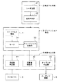
まず、図1のブロック図を参照して、第1実施形態の車両のシートベルト制御装置の構成について説明する。図1に示すように、第1実施形態の車両のシートベルト制御装置は、車両のシートに着座した乗員を拘束するためのシートベルト装置1と、障害物に対する車両の衝突を予知するための衝突予知手段2と、衝突予知手段2が衝突を予知した場合に作動して、乗員を所定張力で拘束するようにシートベルト装置1のシートベルトを所定量巻き取るプリテンショナ手段3と、プリテンショナ手段3を試験作動させて、当該プリテンショナ手段の故障の有無を判定する故障判定手段4とを備えている。
Embodiments of a seat belt control device for a vehicle according to the present invention will be described below with reference to the accompanying drawings.
First, the configuration of the vehicle seatbelt control device of the first embodiment will be described with reference to the block diagram of FIG. As shown in FIG. 1, the seatbelt control device for a vehicle according to the first embodiment includes a
衝突予知手段2は、自車両の前方へ向けてミリ波レーダ電波を発し、反射波を検知するレーダ装置21と、レーダ装置21の検知した前方障害物までの距離、及び自車に対する前方障害物の相対速度等に基づいて、前方障害物が自車と衝突するか否かを判断する衝突予知部22とを有する。
The collision prediction means 2 emits a millimeter-wave radar radio wave toward the front of the host vehicle, detects the reflected wave, the distance to the front obstacle detected by the
プリテンショナ手段3は、衝突予知手段が衝突を予知した場合にシートベルトを巻き取るためのモータ31と、モータ31への通電量をフィードバック制御するフィードバック制御手段とを有する。本実施形態では、モータ31への通電量は、乗員を所定張力で拘束するようにシートベルトを所定量巻き取るように、PID制御される。なお、PID制御のPは、比例(Proportional)を表し、Iは、積分(Integral)を表し、Dは、微分(Differential)を表す。また、モータ31の通電量は、PID制御の下、パルス幅変調(PWM:Pulse Width Modulation)により調節される。
The pretensioner means 3 includes a
故障判定手段4は、試験作動時のモータ31の通電量に基づいて、プリテンショナ手段3の故障の有無を判定する通電量判定部41と、プリテンショナ手段4の試験作動時に、モータ31の通電量を制限する通電量制限部42とを有する。通電量制限部42は、パルス幅のデューティー値を所定値以下(例えば、50%以下)に制限することによって、モータ31の通電量を制限する。
The failure determination unit 4 includes an energization
次に、図2を参照して、シートベルト装置1、及び本実施形態のシートベルト制御装置の車両上の配置を説明する。シートベルト装置1は、既知の構成であるが、シート10の外側部で車室内の床に固定されたアンカ11と、そのアンカ11に固定されたシートベルト12とを有する。シートベルト12には、アンカ11とショルダーアンカ14との間にフック部材15が取り付けられ、フック部材15は、シート10の内側部で床に固定されたバックル16に着脱自在に取り付けられるようになっている。シートベルト12はまた、アンカ11からセンターピラー13の上部に取り付けられたショルダーアンカ14を通って延び、ショルダーアンカ14付近からセンターピラー13内部に導かれる。
Next, with reference to FIG. 2, the arrangement | positioning on the vehicle of the
センターピラー13内部の下部には、衝突予知時にシートベルト12を巻き取るモータ31が配置されている。また、車両100の前部には、レーダ装置21が配置されている。
A
また、図1に示した衝突予知部22、フィードバッグ制御部32、通電量判定部41及び通電量制限部42の各部ロックに相当する機能は、例えば、車両100に搭載されたECU(electric control unit:電子制御装置)7のコンピュータにおいて所定のプログラムを実行することにより、或いは、ECUのICチップにより実現される。
The functions corresponding to the respective locks of the
次に、図3を参照して、本発明の第1実施形態の車両のシートベルト制御装置の動作例を説明する。本実施形態では、エンジン始動時にプリテンショナ装置を試験作動させる。 Next, an operation example of the vehicle seat belt control apparatus according to the first embodiment of the present invention will be described with reference to FIG. In the present embodiment, the pretensioner device is subjected to a test operation when the engine is started.
まず、イグニッション(IG)スイッチ5がオン(ON)操作される(ステップS31)。
イグニッションスイッチがオンになることにより、シートベルト制御装置も作動可能となる。
First, the ignition (IG)
When the ignition switch is turned on, the seat belt control device can also be operated.
次いで、エンジンスタータが回転する(ステップS32)。
なお、スマート・キーレス・エントリー・システムなど、エンジンキーを使用しない場合は、例えば、スタートボタンの押下により、エンジンが始動する。
Next, the engine starter rotates (step S32).
When the engine key is not used, such as a smart keyless entry system, the engine is started by pressing the start button, for example.
次いで、故障判定手段4が、エンジンが始動したか否かを判定する(ステップS33)。 Next, the failure determination means 4 determines whether or not the engine has been started (step S33).
ステップS33でエンジンが始動したと判定した場合、故障判定手段4は、プリテンショナ手段3を試験作動させるため、モータ31に通電する(ステップS34)。試験作動のための通電は、所定の時間、例えば、数秒間から数十秒間行えばよい。また、モータ31への通電量は、フィードバッグ制御部32によりPID制御される。
If it is determined in step S33 that the engine has been started, the failure determination means 4 energizes the
ここで、図4(a)及び図4(b)のグラフに、モータ31の通電量の時間変化を示す。各グラフの横軸は時間を表し、縦軸は電流値を表す。図4(a)のグラフは、プリテンショナ手段3に故障がなく、モータ31が正常に回転する場合のモータ31の通電量の時間変化を示す。また、図4(b)のグラフは、プリテンショナ手段3に故障があり、モータ31が正常に回転しない場合のモータ31の通電量の時間変化を示す。
Here, the time change of the energization amount of the
モータ31が正常な場合、図4(a)のグラフ中の曲線Iに示すように、通電される電流値は、試験作動直後に一時的に高くなった後、低くなる。したがって、プリテンショナ手段3の試験作動による高いモータ音は一時的なものである。
When the
これに対して、モータ31に異常がある場合、図4(b)のグラフ中の破線IIに示すように、PID制御によって、モータ31の通電量が増加し続ける。その結果、PWMにおいてデューティー値が制限されなければ、例えば、デューティー値100%まで、通電量が増加してしまうことになる。その結果、プリテンショナ試験作動による高いモータ音が継続することになる。継続する高いモータ音は、車両の乗員に不快感を与える。
On the other hand, when there is an abnormality in the
そこで、本発明では、プリテンショナ装置3を試験作動させる場合には、通電量制限部42が、モータ31の通電量を制限する。具体的には、モータ31に通電される電流のパルス幅のデューティー値を所定値以下(例えば、50%以下)に制限する。その結果、図4(b)のグラフ中の曲線IIIに示すように、モータ31の通電量が、一定の電流値(Imax)以下に制限される。その結果、モータ31に異常がある場合においても、モータ音の増大が抑制される。
Therefore, in the present invention, when the pretensioner device 3 is subjected to a test operation, the energization
続いて、故障反転手段4の通電量判定部41は、モータ31の通電量に基づいて、プリテンショナ手段の故障の有無を判定する(ステップS35)。判定に当たっては、例えば、モータ31への通電開始から所定時間t経過後(例えば、t=1秒)のモータ31の通電量が、所定の閾値(IT)以上か否かを判定するとよい。所定の閾値(IT)は、モータ31の正常時の通電量と、異常時の通電量との間の値を、経験的に求めるとよい。
Subsequently, the energization
ステップS35で、図4(a)に示すように、所定時間t経過後の通電量が閾値以上の場合、通電量判定部41は、プリテンショナ手段3が故障していると判定する(ステップS37)。その場合、車両のインパネ上の警告灯を点灯させる等して、乗員に異常を報知するようにするとよい。
In step S35, as shown in FIG. 4A, when the energization amount after the elapse of the predetermined time t is equal to or greater than the threshold value, the energization
また、ステップS35で、図4(b)に示すように、所定時間経t過後の通電量が閾値未満の場合、通電量判定部41は、プリテンショナ手段3が故障していないと判定する(ステップS36)。その場合、車両のインパネ上にプリテンション手段3が正常である旨を標示するようにしてもよい。
In step S35, as shown in FIG. 4B, when the energization amount after the elapse of a predetermined time t is less than the threshold value, the energization
このように、本発明によれば、プリテンショナのモータの作動音を大きくすることなく、プリテンショナの故障の有無を判定することができる。 Thus, according to the present invention, it is possible to determine the presence or absence of a failure of the pretensioner without increasing the operating sound of the motor of the pretensioner.
次に、本発明の第2実施形態を説明する。
まず、図5のブロック図を参照して、第2実施形態の車両のシートベルト制御装置の構成について説明する。図1に示すように、第2実施形態の車両のシートベルト制御装置は、故障判定手段4に、プリテンショナ手段3の試験作動時に、車載オーディオ機器6の作動を停止させるオーディオ停止部43を設けた点を除いては、図1に示した第1実施形態の構成と同じである。このため、同一要素の詳細な説明を省略する。
Next, a second embodiment of the present invention will be described.
First, with reference to the block diagram of FIG. 5, the structure of the vehicle seatbelt control apparatus of 2nd Embodiment is demonstrated. As shown in FIG. 1, in the vehicle seat belt control apparatus according to the second embodiment, the failure determination unit 4 is provided with an
次に、図6のフローチャートを参照して、第2実施形の車両のシートベルト制御装置の動作例を説明する。
まず、上述の第1実施形態と同様に、イグニッションスイッチがオン(ON)され(ステップS61)、次いで、エンジンスタータが回転する(ステップS62)。
Next, an example of operation of the vehicle seat belt control apparatus according to the second embodiment will be described with reference to the flowchart of FIG.
First, as in the first embodiment described above, the ignition switch is turned on (step S61), and then the engine starter rotates (step S62).
次いで、第2実施形態では、オーディオ停止部43が、車載のオーディオ機器の作動を停止する(ステップS63)。ここで、停止させるオーディオ機器には、カーラジオ、カーステレオの他、テレビ等のあらゆる車載音響機器を含めることができる。
Next, in the second embodiment, the
次いで、上述の第1実施形態と同様に、エンジンの始動を判定し(ステップS65)、次いで、プリテンショナ手段3を試験作動させるため、モータ31に通電する(ステップS34)。
Next, as in the first embodiment described above, it is determined whether the engine is started (step S65), and then the
次いで、第2実施形態では、オーディオ停止部43が、オーディオ機器の作動の停止を解除する(ステップS66)。
Next, in the second embodiment, the
次いで、上述の第1実施形態と同様に、モータ31の通電量に基づいて、プリテンショナ手段の故障の有無を判定する(ステップS67、S68及びS69)。 Next, as in the first embodiment described above, the presence or absence of failure of the pretensioner means is determined based on the energization amount of the motor 31 (steps S67, S68, and S69).
このように、第2実施形態では、プリテンショナ手段3の試験作動中に、オーディオ機器の作動を停止させた。これにより、通電されたモータ31から電磁ノイズが発生しても、オーディオ機器から耳障りな雑音が発生することが防止される。
Thus, in the second embodiment, the operation of the audio device is stopped during the test operation of the pretensioner means 3. Thereby, even if electromagnetic noise is generated from the energized
上述した各実施形態においては、本発明を特定の条件で構成した例について説明したが、本発明は種々の変更及び組み合わせを行うことができ、これに限定されるものではない。例えば、上述した各実施形態では、エンジン始動後に、プリテンショナ手段を試験作動した例について説明したが、本発明では、試験作動のタイミングはこれに限定されない。例えば、イグニッションのON操作があったときに、エンジンの作動前であっても、プリテンショナ手段の試験作動を行ってもよい。 In each embodiment mentioned above, although the example which constituted the present invention on specific conditions was explained, the present invention can perform various change and combination, and is not limited to this. For example, in each of the above-described embodiments, the example in which the pretensioner means is subjected to the test operation after starting the engine has been described. However, in the present invention, the timing of the test operation is not limited to this. For example, when the ignition is turned on, the pretensioner means may be tested even before the engine is operated.
1 シートベルト装置
2 衝突予知手段
3 プリテンショナ手段
4 故障判定手段
5 イグニッション/エンジン
6 オーディオ機器
7 ECU
21 レーダ装置
22 衝突予知部
31 モータ
32 フィードバック制御部
41 通電量判定部
42 通電量制限部
43 オーディオ停止部
100 車両
DESCRIPTION OF
DESCRIPTION OF
Claims (5)
障害物に対する車両の衝突を予知するための衝突予知手段と、
前記衝突予知手段が衝突を予知した場合に作動して、前記乗員を所定張力で拘束するように前記シートベルト装置のシートベルトを所定量巻き取るプリテンショナ手段と、
前記プリテンショナ手段を試験作動させて、当該プリテンショナ手段の故障の有無を判定する故障判定手段と、
を備え、
前記プリテンショナ手段は、
前記シートベルトを巻き取るためのモータと、
前記モータの通電量をフィードバック制御するフィードバック制御手段と、を有し、
前記故障判定手段は、
試験作動時の前記モータの通電量に基づいて、前記プリテンショナ手段の故障の有無を判定する通電量判定手段と、
前記プリテンショナ手段の試験作動時に、前記モータの通電量を制限する通電量制限手段と、を有し、
前記故障判定手段は、前記プリテンショナ手段の試験作動時に、車載オーディオ機器の作動を停止させるオーディオ停止手段を有する
ことを特徴とする車両のシートベルト制御装置。 A seat belt device for restraining an occupant seated in a vehicle seat;
A collision prediction means for predicting a collision of the vehicle against an obstacle;
Pretensioner means that operates when the collision prediction means predicts a collision and winds up a predetermined amount of the seat belt of the seat belt device so as to restrain the occupant with a predetermined tension;
A failure determination means for performing a test operation of the pretensioner means to determine the presence or absence of a failure of the pretensioner means;
With
The pretensioner means includes
A motor for winding the seat belt;
Feedback control means for feedback-controlling the energization amount of the motor,
The failure determination means includes
An energization amount determining means for determining whether or not the pretensioner means has a failure based on an energization amount of the motor at the time of a test operation,
In a test operation of the pretensioner means, we have a, and energization amount limiting means for limiting the current amount of the motor,
The vehicle seat belt control device according to claim 1, wherein the failure determination means includes an audio stop means for stopping the operation of the in-vehicle audio device during the test operation of the pretensioner means .
ことを特徴とする請求項1記載の車両のシートベルト制御装置。 2. The vehicle seat belt control device according to claim 1, wherein the feedback control means of the pretensioner means performs PID control.
ことを特徴とする請求項1又は2記載の車両のシートベルト制御装置。 3. The energization amount limiting unit of the failure determination unit limits the duty value of the pulse width to a predetermined value or less when the energization amount of the motor is pulse width modulated. The vehicle seat belt control device described.
ことを特徴とする請求項1乃至3のいずれか一項に記載の車両のシートベルト制御装置。 4. The vehicle seat belt control device according to claim 1, wherein the failure determination unit causes the pretensioner unit to perform a test operation when an ignition switch is turned on. 5.
Priority Applications (1)
| Application Number | Priority Date | Filing Date | Title |
|---|---|---|---|
| JP2006251020A JP5013169B2 (en) | 2006-09-15 | 2006-09-15 | Vehicle seat belt control device |
Applications Claiming Priority (1)
| Application Number | Priority Date | Filing Date | Title |
|---|---|---|---|
| JP2006251020A JP5013169B2 (en) | 2006-09-15 | 2006-09-15 | Vehicle seat belt control device |
Publications (2)
| Publication Number | Publication Date |
|---|---|
| JP2008068806A JP2008068806A (en) | 2008-03-27 |
| JP5013169B2 true JP5013169B2 (en) | 2012-08-29 |
Family
ID=39290783
Family Applications (1)
| Application Number | Title | Priority Date | Filing Date |
|---|---|---|---|
| JP2006251020A Expired - Fee Related JP5013169B2 (en) | 2006-09-15 | 2006-09-15 | Vehicle seat belt control device |
Country Status (1)
| Country | Link |
|---|---|
| JP (1) | JP5013169B2 (en) |
Family Cites Families (3)
| Publication number | Priority date | Publication date | Assignee | Title |
|---|---|---|---|---|
| JP2003191821A (en) * | 2001-12-27 | 2003-07-09 | Takata Corp | Seat belt winding device and retractor driving circuit |
| JP2004123038A (en) * | 2002-10-07 | 2004-04-22 | Tokai Rika Co Ltd | Webbing winding device |
| JP2005271769A (en) * | 2004-03-25 | 2005-10-06 | Denso Corp | Seat belt device |
-
2006
- 2006-09-15 JP JP2006251020A patent/JP5013169B2/en not_active Expired - Fee Related
Also Published As
| Publication number | Publication date |
|---|---|
| JP2008068806A (en) | 2008-03-27 |
Similar Documents
| Publication | Publication Date | Title |
|---|---|---|
| JP4934400B2 (en) | Vehicle seat belt device | |
| JP4492732B2 (en) | Motor drive device and drive device state determination method | |
| US9776589B2 (en) | Vehicle control system and method of using the same | |
| WO2004065182A1 (en) | Seatbelt apparatus | |
| JP2005306340A (en) | Vehicle occupant protection device | |
| JP2007145079A (en) | Seat belt retractor, seat belt device, and vehicle with seat belt device | |
| JP2004149048A (en) | Vehicle seat belt device | |
| US7204334B2 (en) | Occupant restraint system | |
| JP4714513B2 (en) | Seat belt retractor, seat belt device, vehicle with seat belt device | |
| JP2007112267A (en) | Seat belt retractor, seat belt device, and vehicle equipped with seat belt device | |
| JP4242166B2 (en) | Seat belt device | |
| JP2007176423A (en) | Seat belt retractor, seat belt device, and vehicle having seat belt device | |
| JP3951959B2 (en) | Vehicle seat belt device | |
| JP5013169B2 (en) | Vehicle seat belt control device | |
| JP4062139B2 (en) | Crew protection device | |
| KR101747882B1 (en) | Seat belt apparatus for vehicles and method for controlling thereof | |
| JP4446692B2 (en) | Vehicle seat belt device | |
| US9738251B2 (en) | Seat belt device | |
| JP4007245B2 (en) | Vehicle seat belt device | |
| JP2018167604A (en) | Seat Belt Device | |
| CN107672555A (en) | Occupant protection system for vehicle | |
| JP2000326824A5 (en) | ||
| US7246822B2 (en) | Motorized seat belt system | |
| JP2008006998A (en) | Seat belt control device, seat belt retractor and vehicle safety device | |
| JP2003175797A (en) | Occupant protection system |
Legal Events
| Date | Code | Title | Description |
|---|---|---|---|
| A621 | Written request for application examination |
Free format text: JAPANESE INTERMEDIATE CODE: A621 Effective date: 20090330 |
|
| A977 | Report on retrieval |
Free format text: JAPANESE INTERMEDIATE CODE: A971007 Effective date: 20110623 |
|
| A131 | Notification of reasons for refusal |
Free format text: JAPANESE INTERMEDIATE CODE: A131 Effective date: 20120126 |
|
| A521 | Written amendment |
Free format text: JAPANESE INTERMEDIATE CODE: A523 Effective date: 20120326 |
|
| TRDD | Decision of grant or rejection written | ||
| A01 | Written decision to grant a patent or to grant a registration (utility model) |
Free format text: JAPANESE INTERMEDIATE CODE: A01 Effective date: 20120510 |
|
| A01 | Written decision to grant a patent or to grant a registration (utility model) |
Free format text: JAPANESE INTERMEDIATE CODE: A01 |
|
| A61 | First payment of annual fees (during grant procedure) |
Free format text: JAPANESE INTERMEDIATE CODE: A61 Effective date: 20120523 |
|
| FPAY | Renewal fee payment (event date is renewal date of database) |
Free format text: PAYMENT UNTIL: 20150615 Year of fee payment: 3 |
|
| R150 | Certificate of patent or registration of utility model |
Ref document number: 5013169 Country of ref document: JP Free format text: JAPANESE INTERMEDIATE CODE: R150 Free format text: JAPANESE INTERMEDIATE CODE: R150 |
|
| LAPS | Cancellation because of no payment of annual fees |