JP5009908B2 - Compression molding machine - Google Patents
Compression molding machine Download PDFInfo
- Publication number
- JP5009908B2 JP5009908B2 JP2008516921A JP2008516921A JP5009908B2 JP 5009908 B2 JP5009908 B2 JP 5009908B2 JP 2008516921 A JP2008516921 A JP 2008516921A JP 2008516921 A JP2008516921 A JP 2008516921A JP 5009908 B2 JP5009908 B2 JP 5009908B2
- Authority
- JP
- Japan
- Prior art keywords
- mold
- axis
- plate
- shaft
- cup
- Prior art date
- Legal status (The legal status is an assumption and is not a legal conclusion. Google has not performed a legal analysis and makes no representation as to the accuracy of the status listed.)
- Expired - Fee Related
Links
Images


Classifications
-
- B—PERFORMING OPERATIONS; TRANSPORTING
- B29—WORKING OF PLASTICS; WORKING OF SUBSTANCES IN A PLASTIC STATE IN GENERAL
- B29C—SHAPING OR JOINING OF PLASTICS; SHAPING OF MATERIAL IN A PLASTIC STATE, NOT OTHERWISE PROVIDED FOR; AFTER-TREATMENT OF THE SHAPED PRODUCTS, e.g. REPAIRING
- B29C31/00—Handling, e.g. feeding of the material to be shaped, storage of plastics material before moulding; Automation, i.e. automated handling lines in plastics processing plants, e.g. using manipulators or robots
- B29C31/04—Feeding of the material to be moulded, e.g. into a mould cavity
- B29C31/042—Feeding of the material to be moulded, e.g. into a mould cavity using dispensing heads, e.g. extruders, placed over or apart from the moulds
- B29C31/048—Feeding of the material to be moulded, e.g. into a mould cavity using dispensing heads, e.g. extruders, placed over or apart from the moulds the material being severed at the dispensing head exit, e.g. as ring, drop or gob, and transported immediately into the mould, e.g. by gravity
-
- B—PERFORMING OPERATIONS; TRANSPORTING
- B29—WORKING OF PLASTICS; WORKING OF SUBSTANCES IN A PLASTIC STATE IN GENERAL
- B29C—SHAPING OR JOINING OF PLASTICS; SHAPING OF MATERIAL IN A PLASTIC STATE, NOT OTHERWISE PROVIDED FOR; AFTER-TREATMENT OF THE SHAPED PRODUCTS, e.g. REPAIRING
- B29C43/00—Compression moulding, i.e. applying external pressure to flow the moulding material; Apparatus therefor
- B29C43/02—Compression moulding, i.e. applying external pressure to flow the moulding material; Apparatus therefor of articles of definite length, i.e. discrete articles
- B29C43/04—Compression moulding, i.e. applying external pressure to flow the moulding material; Apparatus therefor of articles of definite length, i.e. discrete articles using movable moulds
- B29C43/06—Compression moulding, i.e. applying external pressure to flow the moulding material; Apparatus therefor of articles of definite length, i.e. discrete articles using movable moulds continuously movable in one direction, e.g. mounted on chains, belts
- B29C43/08—Compression moulding, i.e. applying external pressure to flow the moulding material; Apparatus therefor of articles of definite length, i.e. discrete articles using movable moulds continuously movable in one direction, e.g. mounted on chains, belts with circular movement, e.g. mounted on rolls, turntables
-
- B—PERFORMING OPERATIONS; TRANSPORTING
- B29—WORKING OF PLASTICS; WORKING OF SUBSTANCES IN A PLASTIC STATE IN GENERAL
- B29C—SHAPING OR JOINING OF PLASTICS; SHAPING OF MATERIAL IN A PLASTIC STATE, NOT OTHERWISE PROVIDED FOR; AFTER-TREATMENT OF THE SHAPED PRODUCTS, e.g. REPAIRING
- B29C43/00—Compression moulding, i.e. applying external pressure to flow the moulding material; Apparatus therefor
- B29C43/02—Compression moulding, i.e. applying external pressure to flow the moulding material; Apparatus therefor of articles of definite length, i.e. discrete articles
- B29C43/18—Compression moulding, i.e. applying external pressure to flow the moulding material; Apparatus therefor of articles of definite length, i.e. discrete articles incorporating preformed parts or layers, e.g. compression moulding around inserts or for coating articles
-
- B—PERFORMING OPERATIONS; TRANSPORTING
- B29—WORKING OF PLASTICS; WORKING OF SUBSTANCES IN A PLASTIC STATE IN GENERAL
- B29C—SHAPING OR JOINING OF PLASTICS; SHAPING OF MATERIAL IN A PLASTIC STATE, NOT OTHERWISE PROVIDED FOR; AFTER-TREATMENT OF THE SHAPED PRODUCTS, e.g. REPAIRING
- B29C43/00—Compression moulding, i.e. applying external pressure to flow the moulding material; Apparatus therefor
- B29C43/32—Component parts, details or accessories; Auxiliary operations
- B29C43/34—Feeding the material to the mould or the compression means
- B29C2043/3466—Feeding the material to the mould or the compression means using rotating supports, e.g. turntables or drums
- B29C2043/3472—Feeding the material to the mould or the compression means using rotating supports, e.g. turntables or drums using star wheels comprising arms
-
- B—PERFORMING OPERATIONS; TRANSPORTING
- B29—WORKING OF PLASTICS; WORKING OF SUBSTANCES IN A PLASTIC STATE IN GENERAL
- B29C—SHAPING OR JOINING OF PLASTICS; SHAPING OF MATERIAL IN A PLASTIC STATE, NOT OTHERWISE PROVIDED FOR; AFTER-TREATMENT OF THE SHAPED PRODUCTS, e.g. REPAIRING
- B29C43/00—Compression moulding, i.e. applying external pressure to flow the moulding material; Apparatus therefor
- B29C43/32—Component parts, details or accessories; Auxiliary operations
- B29C43/36—Moulds for making articles of definite length, i.e. discrete articles
- B29C2043/3676—Moulds for making articles of definite length, i.e. discrete articles moulds mounted on rotating supporting constuctions
- B29C2043/3678—Moulds for making articles of definite length, i.e. discrete articles moulds mounted on rotating supporting constuctions on cylindrical supports with moulds or mould cavities provided on the periphery
- B29C2043/3684—Moulds for making articles of definite length, i.e. discrete articles moulds mounted on rotating supporting constuctions on cylindrical supports with moulds or mould cavities provided on the periphery opening/closing or acting radially, i.e. vertical to the rotation axis
-
- B—PERFORMING OPERATIONS; TRANSPORTING
- B29—WORKING OF PLASTICS; WORKING OF SUBSTANCES IN A PLASTIC STATE IN GENERAL
- B29L—INDEXING SCHEME ASSOCIATED WITH SUBCLASS B29C, RELATING TO PARTICULAR ARTICLES
- B29L2031/00—Other particular articles
- B29L2031/56—Stoppers or lids for bottles, jars, or the like, e.g. closures
- B29L2031/565—Stoppers or lids for bottles, jars, or the like, e.g. closures for containers
-
- Y—GENERAL TAGGING OF NEW TECHNOLOGICAL DEVELOPMENTS; GENERAL TAGGING OF CROSS-SECTIONAL TECHNOLOGIES SPANNING OVER SEVERAL SECTIONS OF THE IPC; TECHNICAL SUBJECTS COVERED BY FORMER USPC CROSS-REFERENCE ART COLLECTIONS [XRACs] AND DIGESTS
- Y10—TECHNICAL SUBJECTS COVERED BY FORMER USPC
- Y10S—TECHNICAL SUBJECTS COVERED BY FORMER USPC CROSS-REFERENCE ART COLLECTIONS [XRACs] AND DIGESTS
- Y10S425/00—Plastic article or earthenware shaping or treating: apparatus
- Y10S425/809—Seal, bottle caps only
Description
本発明の開示は、密閉シェル又は密閉シェル内の密封ライナのような、プラスチック物品を成形するための機械に関する。 The present disclosure relates to a machine for molding plastic articles, such as a hermetic shell or a hermetic liner in a hermetic shell.
圧縮成形密閉シェル又は密閉シェル内の圧縮成形密封ライナのための機械は、一般的に、垂直軸線の周りに回転するターレット又はカルーセルを含む。複数の金型が、回転軸線に平行な垂直軸線に沿って整列した雄及び雌金型部分の形態でカルーセルの周囲の回りに設けられる。カムは、成形された部品が雄金型部分から型抜きされて、プラスチック材料が雌金型部分に注入される開放位置と、雄及び雌金型部分が合わせられてシェル又はライナを圧縮成形する閉鎖位置との間で各対の金型部分の一方又は両方を駆動する。ライナ機械においては、金型部分が開かれた時に、予め作成されたシェルがネスト内に置かれ、金型が閉じられる前に、ライナ材料の注入物又はペレットがシェル内に置かれる。圧縮成形プラスチック密閉シェルのためのこの種の機械は、米国特許第5,670,100号、第5,989,007号、第6,074,583号、及び第6,478,568号に示されている。密閉シェル内の圧縮成形密封ライナのためのこの種の機械は、米国特許第5,451,360号に示されている。 Machines for compression molded sealing shells or compression molded sealing liners in sealed shells typically include a turret or carousel that rotates about a vertical axis. A plurality of molds are provided around the circumference of the carousel in the form of male and female mold parts aligned along a vertical axis parallel to the axis of rotation. The cam compresses the shell or liner by combining the male and female mold parts with an open position where the molded part is stamped from the male mold parts and the plastic material is injected into the female mold parts. Drive one or both of each pair of mold parts to and from the closed position. In a liner machine, when a mold part is opened, a pre-made shell is placed in the nest, and an injection or pellet of liner material is placed in the shell before the mold is closed. Such machines for compression molded plastic hermetic shells are shown in US Pat. Nos. 5,670,100, 5,989,007, 6,074,583, and 6,478,568. Has been. Such a machine for a compression molded sealing liner in a hermetic shell is shown in US Pat. No. 5,451,360.
本発明の開示は、互いに別々に又は互いに組み合わせて実施することができるいくつかの態様を伴っている。
本発明の開示の第1の態様による圧縮成形機械は、軸線の周りの回転のために装着された支持体、及び支持体の周りに配置された複数の角度的に離間した金型を含む。金型の各々は、第1の金型セグメント(第1の金型部分)及び第2の金型セグメント(第2の金型部分)を含む。金型セグメント(金型部分)の少なくとも一方は、プラスチック物品を圧縮成形するための閉鎖位置と、金型から成形物品を除去し、かつ金型に金型注入物を入れるための開放位置との間で他方の金型セグメントに関して移動可能である。金型注入物を金型に順番に入れるための装置が提供される。
The present disclosure entails several aspects that can be implemented separately from one another or in combination with one another.
A compression molding machine according to a first aspect of the present disclosure includes a support mounted for rotation about an axis, and a plurality of angularly spaced molds disposed about the support. Each of the molds includes a first mold segment (first mold part) and a second mold segment (second mold part). At least one of the mold segments (mold part) has a closed position for compression molding the plastic article and an open position for removing the molded article from the mold and placing the mold injection into the mold. Between the other mold segments. An apparatus is provided for sequentially placing mold injections into the mold.
金型注入物を圧縮金型に順番に入れるための装置は、本発明の開示の更に別の態様によれば、第1の軸線の周りの回転のためのプレート、及びプレートの周囲に隣接して担持された少なくとも1つの金型注入物配置機構を含む。金型注入物配置機構は、第1の軸線に垂直な第2の軸線の周りの回転のために装着された配置アームと、金型がプレートの周囲に隣接して順番に通過する時に金型注入物を圧縮金型に入れるためのアームの端部上のカップとを含む。好ましい実施形態では、本発明の開示のこの態様によれば、プレートは、円形の周囲を有し、プレート上の正反対の位置に1対の金型注入物配置機構が存在する。歯車が、金型注入物配置機構の駆動シャフトに連結され、第1の軸線に垂直で互いに同軸の軸線の周りにシャフト及びアームを回転させる。歯車は、静止していることができ、又はプレートの回転とは独立にそれ自体で歯車シャフトによって回転することができる。カッターブレードは、上述の機構がプレート上を回転する時に押出機ノズルなどから金型注入物を切断する。真空及び加圧空気が、好ましくは、カップに選択的に印加され、金型注入物がノズルから金型に運ばれる時にカップに金型注入物を保持し、かつカップから金型内への金型注入物の分離を助ける。 An apparatus for sequentially placing a mold injection into a compression mold is in accordance with yet another aspect of the present disclosure, a plate for rotation about a first axis, and adjacent to the periphery of the plate. And at least one mold implant placement mechanism carried in The mold implant placement mechanism includes a placement arm mounted for rotation about a second axis perpendicular to the first axis, and a mold as the mold passes in turn adjacent to the periphery of the plate. And a cup on the end of the arm for placing the infusate into the compression mold. In a preferred embodiment, according to this aspect of the present disclosure, the plate has a circular perimeter and there is a pair of mold injection placement features at opposite positions on the plate. A gear is coupled to the drive shaft of the mold implant placement mechanism and rotates the shaft and arm about an axis that is perpendicular to the first axis and coaxial with each other. The gear can be stationary or can be rotated by the gear shaft on its own independent of the rotation of the plate. The cutter blade cuts the mold injection from an extruder nozzle or the like when the above-described mechanism rotates on the plate. Vacuum and pressurized air are preferably selectively applied to the cup, holding the mold injection in the cup as the mold injection is carried from the nozzle to the mold, and the mold from the cup into the mold. Helps to separate mold injections.
プラスチック物品を圧縮成形するための機械は、本発明の開示の別の態様によれば、それぞれの第1及び第2の金型経路を通る移動のために支持体上に装着された圧縮金型の第1のアレイ及び圧縮金型の第2のアレイを含む。各金型は、金型セグメントを含み、金型セグメントの少なくとも一方は、閉鎖位置と、成形物品を金型から除去し、かつ金型注入物を金型に入れるための開放位置との間で移動可能である。第1の金型注入物配置装置は、金型注入物を第1のアレイの金型に順番に入れるために第1の経路に隣接して配置される。第2の金型注入物配置装置は、第1の装置と独立に金型注入物を第2のアレイの金型に順番に入れるために第2の経路に隣接して配置される。第1及び第2の金型注入物配置装置の作動は、好ましくは、支持体の移動に同期させられる。支持体は、好ましくは、水平軸線の周りの回転のために装着されたホイールを含み、圧縮金型の第1及び第2のアレイは、ホイールの軸線方向に対向する両側に配置されている。
本発明の開示内容は、その付加的な目的、特徴、利点、及び態様と共に、以下の説明、特許請求の範囲、及び添付の図面から最も良く理解されるであろう。
A machine for compression molding plastic articles, according to another aspect of the present disclosure, is a compression mold mounted on a support for movement through respective first and second mold paths. And a second array of compression molds. Each mold includes a mold segment, at least one of the mold segments is between a closed position and an open position for removing the molded article from the mold and placing the mold injection into the mold. It is movable. A first mold implant placement device is placed adjacent to the first path for sequentially placing the mold implants into the molds of the first array. A second mold implant placement device is positioned adjacent to the second path to sequentially place the mold implants into the second array of molds independent of the first device. The operation of the first and second mold implant placement devices is preferably synchronized to the movement of the support. The support preferably includes a wheel mounted for rotation about a horizontal axis, and the first and second arrays of compression molds are disposed on opposite sides of the wheel in the axial direction.
The disclosure of the present invention, together with its additional objects, features, advantages, and aspects, will be best understood from the following description, the claims, and the accompanying drawings.
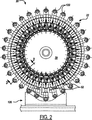
図1〜2は、プラスチック密閉シェルを圧縮成形するための機械20を示している。機械20は、離間した支持体26間のシャフト24上に装着されたホイール22を含む。シャフト24は、プーリ30及びベルト32により、シャフト24及びホイール22を水平軸線の周りに回転させるためのモータに連結されている。ホイール22は、ハブ37(シャフト24の一部とすることができる)、及びハブ37から半径方向に延びる支持体39を含む。支持体39は、ディスクなどを含むことができ、又は角度的に離間した半径方向に延びる複数の支持スポーク38の形態をとることができる。各支持スポーク38は、その外側端部で中空である。ロッド40は、各スポーク38の中空外側端部内でスリーブベアリング42(図3B〜3C)によって摺動自在に支持される。クロスバー50が、各ロッド40の端部に連結され、従って、ロッド40及びバー50の組合せは、図1の接線方向から見た時にほぼT字形である。複数の角度的に離間した金型52は、ホイール22の周囲の周りに、好ましくは、ホイールの両側上に配置される。各金型52は、関連のスポーク38及びロッド40上のクロスバー50の端部上に配置される。金型52の全ては、好ましくは、同一である。各金型は、1対の金型セグメント(金型部分)を含み、金型セグメントの少なくとも一方は、成形物品が金型から除去され、かつ新たな金型注入物が金型に入れられる開放位置と、この物品が圧縮成形される閉鎖位置との間で、他方に関して半径方向に移動可能である。
1-2 show a
カム126は、図2に最も良く見られるように、好ましくは、ホイール22がその水平軸線の周りに回転する時に、金型52のカム従動ローラ122に順番に係合するようにホイール22の周囲の下部の円弧に沿って配置される。図2の向きにおいて、ホイール22の反時計回りの回転中に、金型52の各対の従動ローラ122は、金型52を開くために順番にカム126によって係合されて捕捉される。各金型が次に完全に開かれた時、成形された部品又は物品は、適切な部品除去機構128(図1)によって金型空洞から除去される。次に、新たな金型注入物が、適切な注入物配置装置130によって各金型空洞内に配置される。ホイール22が回転を続ける時、金型は閉鎖されている。支持体39及び/又はスポーク38は、好ましくは、完全閉鎖位置において金型部分を互いに係止するためのラッチを担持し、従って、カム126がホイール22の周囲周り全体に延びている必要がない。
The
図3〜7は、本発明の開示の態様による金型注入物配置装置130(図1)を示している。図3〜7の金型注入物配置装置130は、プレート320及びカラー322と同軸の第1の軸線の周りの回転のためにカラー322に連結された好ましくは円形のプレート320を含む。回転のこの軸線は、1つの好ましい実施例では、好ましくは、水平軸線の周りに回転する金型ホイール22と組み合わされた垂直軸である。ホイール22及びそれによって担持された金型52の金型部分56は、図3〜7に図式的にのみ示されていることが認識されるであろう。金型注入物配置装置130は、垂直軸カルーセル型圧縮成形機械と組み合わせても同様に使用することができ、金型空洞56がプレート320の周囲に隣接して順番に水平に出現することに注意されたい。配置装置130は、密閉シェルを圧縮成形するために金型注入物を入れ、又は予備成形シェル内でライナを圧縮成形するために使用することができる。
3-7 illustrate a mold implant placement device 130 (FIG. 1) according to aspects of the present disclosure. The mold
少なくとも1つの金型注入物切断及び配置機構324は、金型注入物を金型部分56に順番に運び、かつ金型注入物を金型部分に入れる押出機ノズル325から金型注入物を切断するために、ホイール320の周囲に配置される。図示の実施形態では、プレート320の正反対の両側に位置する1対の金型注入物切断及び配置機構324が存在する。多くの数の機構324をプレート320の周りに、好ましくは等角度の増分で置くことができる。機構324は、好ましくは、構造上同一である。各機構324は、好ましくは、プレート320の周囲に隣接して装着されたベアリングブロック326、及びプレート320の回転軸に垂直な第2の軸線の周りの回転のためにベアリングブロック326を通して延びる駆動シャフト328を含む。駆動シャフト328の回転軸は、好ましくは、共線である。アーム330は、シャフト回転の軸線に対して角度を成し、好ましくは、シャフト回転の軸線に垂直に各シャフト328の端部から延びている。半径方向外側に開く中空カップ332は、各アーム330の端部に装着されている。従って、各カップ332は、シャフト328の軸線の周りに回転し、シャフト328は、プレート320の軸線の周りに回転する。ナイフブロック334は、本実施例では、各ベアリングブロック332上に装着されている。カッターブレード又はナイフ336は、シャフト328上の各ブロック334からシャフト328の軸線に対して角度を成して延びている。カッターブレード336は、関連のカップ332がノズルの下に位置する時に、ノズル325から金型注入物338を切断するためにノズル325の出口の下に順番に通される。ノズル325は、この実施形態では、プレート320の周囲上に位置している。
At least one mold injection cutting and
各シャフト328の内側端部は、歯車340に連結されている。歯車340は、次に、プレート320及びカラー322を通して、好ましくは、カラー及びプレートと同軸に延びる歯車シャフト344の端部上に装着された歯車342に連結されている。従って、歯車シャフト344の回転は、歯車340、342により、駆動シャフト328、アーム330、及びカップ332に伝えられる。カラー322及び歯車シャフト344は、第1の軸線の周りのカラー及び歯車シャフトの回転を制御するための適切な手段346に連結されている。これらの制御手段346は、カラー322に連結された第1のモータ348、及び歯車シャフト344に連結された第2のモータ350を含むものとして図3に示されている。モータ348、350は、カラー322及びプレート320、並びに歯車シャフト344及びカップ322を同期して、しかし、好ましくはこの実施形態では互いに独立に回転させるための適切な制御装置352に連結されている。モータ348、350は、独立に制御可能なサーボモータを含むことができる。代替的に、歯車シャフト344及びカラー322は、適切な歯車及びプーリなどによってホイール22を回転させるための駆動モータに連結することができる。
The inner end of each
作動中、適切な樹脂材料の金型注入物338は、機構324が次にノズル325の下を通過する時に、カッターブレード336によってノズル325から切断される。金型注入物338が切断される時、アーム330及びカップ332は、好ましくは、切断された金型注入物を受けるために、垂直上方に(図4に示すように)方向付けられる。方向360におけるシャフト328、アーム330、及びカップ332の継続する回転(図4に実線で示す位置から、図3及び図5の位置を通って、図6のかつ図4で透視した位置まで)は、金型注入物338を下方に方向付けられた位置に運び、下方点でカップ332及び金型注入物338は、金型注入物を入れるために金型部分56内に配置されている。溶融注入物338、カップ332、及び金型部分56の間の表面張力は、金型注入物を保持して運ぶために使用することができる。しかし、金型注入物の捕捉、運搬、及び放出は、より好ましくは、関連のシャフト328及びアーム330を通して各カップ332に連結された制御装置354(図4)によって補助される。制御装置354は、カップが金型部分56内に配置されるまで、カップ内で切断された金型注入物338を捕捉して保持するために選択的にカップ332に真空を引き、金型部分56内で金型注入物338の放出及び配置を助けるために、シャフト328、アーム330、及びカップ332を通して選択的に加圧空気を加える。従って、各金型注入物338は、金型部分56内に積極的に置かれ、その結果、金型注入物の配置が、圧縮成形作動中に材料の流れを増加するように制御される。この制御された注入物配置は、一般的に金型部分への金型注入物の自由落下を伴い、多くの場合に放出時に空気圧及び/又は配置機構の垂直加速によって助けられ、結果として金型部分への金型注入物の望ましくない配置及び圧縮成形中の材料の不均一な流れに至る可能性がある従来技術と対比することができる。
In operation, a
図5は、ホイール22が方向356に回転し、プレート320が方向358に向けて回転し、かつシャフト328が方向360に向けて回転する時の金型注入物配置アーム330及びカップ332の金型部分56への最初の進入を示している。ホイール22、シャフト328、及びプレート320の更なる回転は、アーム330を図4及び図6において示された垂直方向に持ってきて、その点で金型注入物は、金型部分内に放出される。図7に示すように、更なる回転は、アーム330及びカップ332を部分56から除去し始める。プレートの回転358の速度は、ホイール22が連続的に回転する間にアーム330及びカップ332が空洞56の端部とのアーム及びカップの干渉なしに金型部分56から除去される程度であることに注意されたい。プレート320は、好ましくは、一定の角速度で方向358に向けて回転し、シャフト328、アーム330、及びカップ332は、好ましくは、一定の角速度で方向360に向けて回転する。ホイール22は、好ましくは、一定の角速度で方向356に向けて回転する。カップ332の一方が金型部分56の注入物配置位置にある時、プレート320の反対側のカップ332も下向き方向にあることが図3において注意されたい。従って、機械始動中、注入物338は、金型部分56に置かれずにカップ332に保持され、次に、プレート320の反対側で不用品又は再利用のために排出することができる。
FIG. 5 illustrates mold
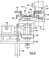
図8〜11は、本発明の開示による別の例示的金型注入物配置装置130(図2)を示している。図3〜7における番号と同一の図8〜11における参照番号は、同一又は関連の構成要素を示している。図8〜11の説明は、図8〜11の実施形態と図3〜7の実施形態の間の違いに主として向けられることになる。
図8〜11の実施形態では、押出機ノズル325は、スリーブ322及び歯車シャフト344の軸線に平行であるが、そこから横方向にオフセットしており、図3〜7の実施形態におけるように機構及びプレートの上ではなく、機構326及びプレート320の下に位置している。ペレットカッターナイフ392は、ノズル325の出口の上のプレート396に沿った回転のためのブレードシャフト394にアーム393によって連結されている。シャフト394の軸線は、スリーブ322及びシャフト344の軸線に平行であるが、そこから横方向に離間している(図10)。カラー322及びシャフト394は、ベルト345によってモータ346に連結されている。シャフト344は、この実施形態では、静止しており、すなわち、モータ駆動ではない。シャフト344は、カラー322及びプレート320に対してシャフト344及び歯車342の「タイミング」を調節するための位相調節器438(図10)によって支持構造体436に連結されている。従って、シャフト344及び歯車342は、この実施形態では、装置の通常作動中、すなわち、位相調節器438による最初の位相調節の後では静止している。モータ346は、ホイール22と同期してカラー322及びプレート320を回転させ、かつ駆動シャフト394及びブレード392を回転させるための適切な制御装置352に連結されている。モータ346は、独立して制御可能なサーボモータを含むことができる。代替的に、カラー322及びシャフト394は、適切な歯車又はプーリなどによってホイール22(図1及び図2)に連結することができる。押出機からの熱溶解物は、定量ポンプ382(図6)、通路384、及び誘導ゲート386により、ノズル325に給送することができる。誘導ゲート386は、アーム388により、シリンダ又はアクチュエータ390に連結されている。
8-11 illustrate another exemplary mold implant placement device 130 (FIG. 2) in accordance with the present disclosure. Reference numerals in FIGS. 8-11 that are the same as those in FIGS. 3-7 indicate the same or related components. The description of FIGS. 8-11 will be primarily directed to the differences between the embodiments of FIGS. 8-11 and the embodiments of FIGS.
In the embodiment of FIGS. 8-11, the
作動中、適切な樹脂材料の金型注入物は、機構324が次にノズル325上を通過する時、カッターナイフ392によってノズル325から切断される。金型注入物が切断される時、アーム330及びカップ332は、好ましくは、切断された金型注入物を受けるために垂直下方に方向付けられる。プレート320、シャフト328、アーム330、及びカップ332の継続する回転は、金型注入物を下方に方向付けられた位置に運び、その位置でカップ332及び金型注入物338は、金型注入物を入れるための金型部分56内に配置されている。溶融注入物及びカップ332及び金型部分の間の表面張力は、金型注入物を保持して運ぶために使用することができる。しかし、金型注入物の捕捉、運搬、及び放出は、より好ましくは、関連のシャフト328及びアーム330を通して各カップ332に連結された制御装置354(図4)によって助けられる。制御装置354は、カップが金型部分56(図8)内に配置されるまで、カップ内で切断された金型注入物を捕捉しかつ保持するために、選択的にカップ332に真空を引き、金型部分56内で金型注入物の放出及び配置を助けるために、シャフト328、アーム330、及びカップ332を通して、選択的に加圧空気を加える。従って、各金型注入物は、金型部分56内に積極的に置かれ、その結果、金型注入物の配置が、圧縮成形作動中に材料の流れを増加するように制御される。
In operation, a mold injection of suitable resin material is cut from
図1、図8、及び図9はまた、成形部品除去装置128の実施例を示している。シュート410は、金型の開放位置において金型セグメント54の下に位置決めされる。成形された密閉シェルは、金型52から型抜きされ、シュート410に落下する。成形された密閉シェルをシュート410上に拘束し、シュートに沿ってシェルを押すために、1つ又はそれよりも多くのフィンガ412が、金型注入物配置機構のプレート320によって担持されている。
1, 8, and 9 also show an embodiment of the molded
図12は、図9のブレード392の弓形の刃先ではなく、角張った直線の刃先を有するカッターブレード392aを示している。図13は、一部の用途において金型注入物の横方向の運動の防止を助けることができるV字形刃先を有するカッターブレード392bを示している。
図14及び図15は、図3〜7及び図8〜11の実施形態におけるカップ332に対する修正として収集カップ332a、332bを示している。カップ332は、比較的堅固な構成であるが、カップ332a及び332bは、プラスチック、好ましくは例えばシリコーンのような可撓性で弾力性のある材料の可撓性ベローズ形状の構成である。
FIG. 12 shows a
14 and 15 show collection cups 332a, 332b as a modification to
すなわち、上述の目的及び目標の全てを十分に満足するプラスチック物品を圧縮成形するための機械及び方法を開示した。本発明の開示は、いくつかの現在好ましい実施形態に関連して示し、いくつかの付加的な修正及び変形を説明した。他の修正及び変形は、当業者には容易に想起されるであろう。本発明の開示は、そのような全ての修正及び変形を特許請求の範囲の精神及びその広範な範囲に該当するものとして含むものとする。 That is, a machine and method for compression molding a plastic article that fully satisfies all of the above objectives and goals has been disclosed. The present disclosure has been presented in connection with some currently preferred embodiments and described some additional modifications and variations. Other modifications and variations will readily occur to those skilled in the art. The disclosure of the present invention is intended to cover all such modifications and variations as fall within the spirit and broad scope of the appended claims.
Claims (31)
を含み、
前記金型(52)の各々は、第1の金型セグメント及び第2の金型セグメントを含み、 前記金型セグメントの少なくとも一方は、プラスチック物品を圧縮成形するための閉鎖位置と、該金型から成形物品を除去し、かつ該金型に金型注入物を入れるための開放位置との間で他方の金型セグメントに対して移動可能であり、
第1の軸線周りの回転のためのプレート(320)及び該プレートの周囲に隣接して担持された金型注入物配置機構(324)、
を含む金型注入物を前記金型に順番に入れるための装置(130)、
を更に含み、
前記金型注入物配置機構は、前記第1の軸線に垂直な第2の軸線の周りの回転のために装着された配置アーム(330)、及び前記金型が前記プレートの前記周囲に隣接して順番に通過する時に金型注入物を該金型に入れるための前記アームの端部のカップ(332又は332a又は332b)を含む、
ことを特徴とする圧縮成形機械。A wheel (22) mounted for rotation about an axis and a plurality of angularly spaced molds (52) disposed about the wheel;
Including
Each of the molds (52) includes a first mold segment and a second mold segment, at least one of the mold segments being in a closed position for compression molding a plastic article, and the mold Moveable relative to the other mold segment between an open position for removing the molded article from the mold and placing the mold injection into the mold,
A plate (320) for rotation about a first axis and a mold implant placement mechanism (324) carried adjacent to the periphery of the plate;
An apparatus (130) for sequentially placing a mold injection comprising:
Further including
The mold implant placement mechanism includes a placement arm (330) mounted for rotation about a second axis perpendicular to the first axis, and the mold is adjacent to the periphery of the plate. A cup (332 or 332a or 332b) at the end of the arm for placing the mold injection into the mold as it passes in turn.
A compression molding machine characterized by that.
前記カッターブレード(336)は、前記第1の軸線に平行な第3の軸線の周りの回転のためにブレードシャフト(394)に連結されたアーム(393)上にある、
ことを特徴とする請求項4に記載の機械。The nozzle (325) is spaced from the first axis;
The cutter blade (336) is on an arm (393) connected to a blade shaft (394) for rotation about a third axis parallel to the first axis.
The machine according to claim 4.
第1の軸線の周りの回転のためのプレート(320)、及び該プレートの周囲に隣接して担持された少なくとも1つの金型注入物配置機構(324)、
を含み、
前記金型注入物配置機構は、前記第1の軸線に垂直な第2の軸線の周りの回転のために装着された配置アーム(330)と、前記金型が前記プレートの前記周囲に隣接して順番に通過する時に金型注入物を金型に入れるための該アームの端部のカップ(332又は332a又は332b)とを含む、
ことを特徴とする装置。An apparatus for sequentially placing a mold injection into a compression mold,
A plate (320) for rotation about a first axis, and at least one mold implant placement mechanism (324) carried adjacent to the periphery of the plate;
Including
The mold implant placement mechanism includes a placement arm (330) mounted for rotation about a second axis perpendicular to the first axis, and the mold is adjacent to the periphery of the plate. A cup (332 or 332a or 332b) at the end of the arm for placing the mold injection into the mold as it passes in turn.
A device characterized by that.
前記カッターブレードは、前記第1の軸線に平行な第3の軸線の周りの回転のためにブレードシャフト(394)にアーム(393)によって連結された(336)である、
ことを特徴とする請求項16に記載の装置。The nozzle (325) is spaced from the first axis;
The cutter blade is (336) connected by an arm (393) to a blade shaft (394) for rotation about a third axis parallel to the first axis.
The apparatus according to claim 16.
前記カッターブレード(336)は、前記第1の軸線に平行な第3の軸線の周りの回転のためにブレードシャフト(394)にアーム(393)によって連結されている、
ことを特徴とする請求項22に記載の装置。The nozzle (325) is spaced from the first axis;
The cutter blade (336) is connected by an arm (393) to a blade shaft (394) for rotation about a third axis parallel to the first axis.
The apparatus of claim 22.
前記カッターブレード(336)は、該第1の軸線に平行な第3の軸線の周りの回転のためのブレードシャフト(394)にアーム(393)によって連結されている、
ことを特徴とする請求項26に記載の装置。The nozzle (325) is spaced from the first axis;
The cutter blade (336) is connected by an arm (393) to a blade shaft (394) for rotation about a third axis parallel to the first axis.
27. The apparatus of claim 26.
Applications Claiming Priority (3)
| Application Number | Priority Date | Filing Date | Title |
|---|---|---|---|
| US11/156,115 US7247014B2 (en) | 2005-06-17 | 2005-06-17 | Compression molding machine |
| US11/156,115 | 2005-06-17 | ||
| PCT/US2006/021601 WO2006138089A1 (en) | 2005-06-17 | 2006-06-05 | Compression molding machine |
Publications (3)
| Publication Number | Publication Date |
|---|---|
| JP2008543612A JP2008543612A (en) | 2008-12-04 |
| JP2008543612A5 JP2008543612A5 (en) | 2012-05-10 |
| JP5009908B2 true JP5009908B2 (en) | 2012-08-29 |
Family
ID=37027714
Family Applications (1)
| Application Number | Title | Priority Date | Filing Date |
|---|---|---|---|
| JP2008516921A Expired - Fee Related JP5009908B2 (en) | 2005-06-17 | 2006-06-05 | Compression molding machine |
Country Status (13)
| Country | Link |
|---|---|
| US (1) | US7247014B2 (en) |
| EP (1) | EP1901899A1 (en) |
| JP (1) | JP5009908B2 (en) |
| CN (1) | CN101198453B (en) |
| AR (1) | AR055798A1 (en) |
| AU (1) | AU2006259758B2 (en) |
| BR (1) | BRPI0611933A2 (en) |
| CA (1) | CA2596804C (en) |
| MX (1) | MX2007009736A (en) |
| MY (1) | MY146767A (en) |
| RU (1) | RU2384406C2 (en) |
| WO (1) | WO2006138089A1 (en) |
| ZA (1) | ZA200707400B (en) |
Families Citing this family (7)
| Publication number | Priority date | Publication date | Assignee | Title |
|---|---|---|---|---|
| ITMO20060089A1 (en) * | 2006-03-17 | 2007-09-18 | Sacmi | EQUIPMENT AND METHODS |
| US7357631B2 (en) | 2006-05-10 | 2008-04-15 | Owens-Illinois Closures, Inc. | Apparatus for placing mold charges in a compression molding machine |
| US7566215B2 (en) * | 2007-07-30 | 2009-07-28 | Rexam Closure Systems Inc. | Apparatus for placing mold charges into a compression molding machine |
| US7628601B2 (en) * | 2007-07-30 | 2009-12-08 | Rexam Closure Systems Inc. | Machine for compression molding plastic articles |
| US7621735B2 (en) * | 2007-10-18 | 2009-11-24 | Rexam Closure Systems Inc. | Apparatus for placing mold charges into a compression molding machine |
| ITUB20154653A1 (en) | 2015-10-14 | 2017-04-14 | Sacmi | Apparatus and method for processing doses. |
| TW202344367A (en) * | 2022-05-04 | 2023-11-16 | 義大利商沙克米機械合作伊莫拉公司 | Apparatus for compression moulding concave objects |
Family Cites Families (27)
| Publication number | Priority date | Publication date | Assignee | Title |
|---|---|---|---|---|
| US3635612A (en) | 1969-10-29 | 1972-01-18 | Fortin Latchford Ltd | Molding machine |
| US3867081A (en) | 1972-02-09 | 1975-02-18 | Gros Ite Industries | Apparatus for dispensing predetermined quantities of plastic material by blade means having rotational and translational movement |
| US3782329A (en) | 1972-02-09 | 1974-01-01 | Gros Ite Industries | Apparatus for dispensing plastic material or the like |
| US3955605A (en) | 1975-02-27 | 1976-05-11 | H-C Industries, Inc. | Apparatus and method for supplying a metered charge at any feed rate |
| JPS5299186A (en) | 1976-02-16 | 1977-08-19 | Crown Cork Japan | Apparatus for distributing lining material to cap |
| US4080136A (en) | 1976-09-02 | 1978-03-21 | H-C Industries, Inc. | Apparatus for dispensing metered charges of material |
| US4277431A (en) | 1977-11-30 | 1981-07-07 | H-C Industries, Inc. | Method of dispensing metered charges of material |
| JPS559860A (en) | 1978-07-10 | 1980-01-24 | Japan Crown Cork Co Ltd | Cap shellsigma interior lining material distributing device |
| JPS60245517A (en) | 1984-05-22 | 1985-12-05 | Toyo Seikan Kaisha Ltd | Compression molding apparatus |
| JPH057378A (en) * | 1991-06-27 | 1993-01-14 | Toshiba Corp | Feeding detection circuit for network interface |
| DE4214481C1 (en) | 1992-05-07 | 1993-05-19 | Hermann Berstorff Maschinenbau Gmbh, 3000 Hannover, De | |
| US5370519A (en) | 1993-01-26 | 1994-12-06 | Zapata Technologies, Inc. | Apparatus for cutting and dispensing cap lining material |
| US5386971A (en) | 1993-07-22 | 1995-02-07 | Owens-Illinois Closure Inc. | Plastic pellet delivery system and method of use |
| US5368094A (en) * | 1993-11-02 | 1994-11-29 | Hung; Chin-Ping | Bipartite heat sink positioning device for computer chips |
| JP3273285B2 (en) * | 1994-04-11 | 2002-04-08 | 日本クラウンコルク株式会社 | Synthetic resin container lid manufacturing equipment |
| US5603964A (en) | 1994-10-07 | 1997-02-18 | Owens-Illinois Closure Inc. | Apparatus for cutting and delivering plastic gobs |
| US5611983A (en) | 1995-04-28 | 1997-03-18 | Shell Oil Company | Process for pelletizing polymer |
| US5596251A (en) | 1995-06-07 | 1997-01-21 | Alcoa Closure Systems International, Inc. | Servo motor-driven plastic cutter system for compression molding |
| US5866177A (en) * | 1997-05-16 | 1999-02-02 | Owens-Illinois Closure Inc. | Apparatus for compression molding plastic articles |
| US6368094B1 (en) | 1999-11-22 | 2002-04-09 | Alcoa Closure Systems International | Multi-path compression molding apparatus |
| US6422854B1 (en) | 1999-11-22 | 2002-07-23 | Alcoa Closure Systems International | Rotary cutter for cutting, measuring, and dispensing molten plastic |
| ITBO20020683A1 (en) * | 2002-10-31 | 2004-05-01 | Sacmi | DEVICE FOR THE COLLECTION OF DOSES OF PLASTIC MATERIAL FROM AN EXTRUDER |
| JP2004188080A (en) * | 2002-12-13 | 2004-07-08 | Aruze Corp | Game machine |
| ITRE20030005A1 (en) | 2003-01-20 | 2004-07-21 | Sacmi | METHOD FOR FORMING OBJECTS BY MOLDING |
| ITMO20030289A1 (en) | 2003-10-23 | 2005-04-24 | Sacmi | EQUIPMENT, METHOD AND ARTICLE. |
| US7178562B2 (en) | 2004-04-08 | 2007-02-20 | Graham Packaging Pet Technologies Inc. | Pellet transfer apparatus and method |
| ITRE20040040A1 (en) | 2004-04-23 | 2004-07-23 | Sacmi | METHOD AND EQUIPMENT FOR TRANSFERRING DOSED BODIES OF POLYMERIC MATERIAL TO THE DIE CAVITY OF A MOLDING MACHINE |
-
2005
- 2005-06-17 US US11/156,115 patent/US7247014B2/en not_active Expired - Fee Related
-
2006
- 2006-06-05 RU RU2008101701/12A patent/RU2384406C2/en not_active IP Right Cessation
- 2006-06-05 MY MYPI20062580A patent/MY146767A/en unknown
- 2006-06-05 CA CA2596804A patent/CA2596804C/en not_active Expired - Fee Related
- 2006-06-05 JP JP2008516921A patent/JP5009908B2/en not_active Expired - Fee Related
- 2006-06-05 AU AU2006259758A patent/AU2006259758B2/en not_active Ceased
- 2006-06-05 WO PCT/US2006/021601 patent/WO2006138089A1/en active Application Filing
- 2006-06-05 CN CN2006800218217A patent/CN101198453B/en not_active Expired - Fee Related
- 2006-06-05 BR BRPI0611933-6A patent/BRPI0611933A2/en not_active IP Right Cessation
- 2006-06-05 MX MX2007009736A patent/MX2007009736A/en active IP Right Grant
- 2006-06-05 ZA ZA200707400A patent/ZA200707400B/en unknown
- 2006-06-05 EP EP06772058A patent/EP1901899A1/en not_active Withdrawn
- 2006-06-13 AR ARP060102495A patent/AR055798A1/en active IP Right Grant
Also Published As
| Publication number | Publication date |
|---|---|
| JP2008543612A (en) | 2008-12-04 |
| US7247014B2 (en) | 2007-07-24 |
| CN101198453B (en) | 2011-11-23 |
| US20060286192A1 (en) | 2006-12-21 |
| AU2006259758B2 (en) | 2011-05-19 |
| MY146767A (en) | 2012-09-14 |
| ZA200707400B (en) | 2008-12-31 |
| RU2384406C2 (en) | 2010-03-20 |
| BRPI0611933A2 (en) | 2009-06-16 |
| RU2008101701A (en) | 2009-07-27 |
| CA2596804C (en) | 2013-05-14 |
| CA2596804A1 (en) | 2006-12-28 |
| AU2006259758A1 (en) | 2006-12-28 |
| WO2006138089A1 (en) | 2006-12-28 |
| MX2007009736A (en) | 2007-09-25 |
| CN101198453A (en) | 2008-06-11 |
| EP1901899A1 (en) | 2008-03-26 |
| AR055798A1 (en) | 2007-09-05 |
Similar Documents
| Publication | Publication Date | Title |
|---|---|---|
| JP5009908B2 (en) | Compression molding machine | |
| JP4676200B2 (en) | An apparatus for removing a portion of the plastic material extruded from the extruder to the outside as a material lump for article formation or the like | |
| JP2006514889A (en) | Equipment for molding caps by compression molding | |
| US7566215B2 (en) | Apparatus for placing mold charges into a compression molding machine | |
| EP2173530A1 (en) | Machine for compression molding plastic articles | |
| RU2404890C2 (en) | Feed of moulding compound portion | |
| US7357631B2 (en) | Apparatus for placing mold charges in a compression molding machine | |
| US7261546B1 (en) | Apparatus for severing mold charges in a compression molding machine | |
| EP2207657B1 (en) | Apparatus for placing mold charges into a compression molding machine | |
| CA2596815C (en) | Vertical wheel machine and method for compression molding sealing liners | |
| JPH0341319B2 (en) |
Legal Events
| Date | Code | Title | Description |
|---|---|---|---|
| A621 | Written request for application examination |
Free format text: JAPANESE INTERMEDIATE CODE: A621 Effective date: 20090604 |
|
| A977 | Report on retrieval |
Free format text: JAPANESE INTERMEDIATE CODE: A971007 Effective date: 20110914 |
|
| A131 | Notification of reasons for refusal |
Free format text: JAPANESE INTERMEDIATE CODE: A131 Effective date: 20110920 |
|
| A601 | Written request for extension of time |
Free format text: JAPANESE INTERMEDIATE CODE: A601 Effective date: 20111220 |
|
| A602 | Written permission of extension of time |
Free format text: JAPANESE INTERMEDIATE CODE: A602 Effective date: 20111228 |
|
| A524 | Written submission of copy of amendment under section 19 (pct) |
Free format text: JAPANESE INTERMEDIATE CODE: A524 Effective date: 20120316 |
|
| TRDD | Decision of grant or rejection written | ||
| A01 | Written decision to grant a patent or to grant a registration (utility model) |
Free format text: JAPANESE INTERMEDIATE CODE: A01 Effective date: 20120501 |
|
| A01 | Written decision to grant a patent or to grant a registration (utility model) |
Free format text: JAPANESE INTERMEDIATE CODE: A01 |
|
| A61 | First payment of annual fees (during grant procedure) |
Free format text: JAPANESE INTERMEDIATE CODE: A61 Effective date: 20120531 |
|
| R150 | Certificate of patent or registration of utility model |
Free format text: JAPANESE INTERMEDIATE CODE: R150 |
|
| FPAY | Renewal fee payment (event date is renewal date of database) |
Free format text: PAYMENT UNTIL: 20150608 Year of fee payment: 3 |
|
| FPAY | Renewal fee payment (event date is renewal date of database) |
Free format text: PAYMENT UNTIL: 20150608 Year of fee payment: 3 |
|
| S111 | Request for change of ownership or part of ownership |
Free format text: JAPANESE INTERMEDIATE CODE: R313113 |
|
| FPAY | Renewal fee payment (event date is renewal date of database) |
Free format text: PAYMENT UNTIL: 20150608 Year of fee payment: 3 |
|
| R350 | Written notification of registration of transfer |
Free format text: JAPANESE INTERMEDIATE CODE: R350 |
|
| LAPS | Cancellation because of no payment of annual fees |