JP5008729B2 - Control center - Google Patents
Control center Download PDFInfo
- Publication number
- JP5008729B2 JP5008729B2 JP2009553330A JP2009553330A JP5008729B2 JP 5008729 B2 JP5008729 B2 JP 5008729B2 JP 2009553330 A JP2009553330 A JP 2009553330A JP 2009553330 A JP2009553330 A JP 2009553330A JP 5008729 B2 JP5008729 B2 JP 5008729B2
- Authority
- JP
- Japan
- Prior art keywords
- light
- control center
- lens
- load state
- light emitting
- Prior art date
- Legal status (The legal status is an assumption and is not a legal conclusion. Google has not performed a legal analysis and makes no representation as to the accuracy of the status listed.)
- Active
Links
Images


Classifications
-
- G—PHYSICS
- G02—OPTICS
- G02B—OPTICAL ELEMENTS, SYSTEMS OR APPARATUS
- G02B6/00—Light guides; Structural details of arrangements comprising light guides and other optical elements, e.g. couplings
- G02B6/0001—Light guides; Structural details of arrangements comprising light guides and other optical elements, e.g. couplings specially adapted for lighting devices or systems
- G02B6/0011—Light guides; Structural details of arrangements comprising light guides and other optical elements, e.g. couplings specially adapted for lighting devices or systems the light guides being planar or of plate-like form
- G02B6/0033—Means for improving the coupling-out of light from the light guide
- G02B6/0035—Means for improving the coupling-out of light from the light guide provided on the surface of the light guide or in the bulk of it
Description
この発明は、複数の列盤の各々を構成するコントロールユニットの前面パネルに、負荷状態を表示する負荷状態監視画面表示装置、およびこの負荷状態監視画面表示装置の近傍に位置する異常表示装置を備えたコントロールセンタに関するものである。 The present invention includes a load state monitoring screen display device that displays a load state on a front panel of a control unit that constitutes each of a plurality of rows, and an abnormality display device that is located in the vicinity of the load state monitoring screen display device. Related to the control center.
コントロールセンタを構成する複数の列盤の各々を構成するコントロールユニットは例えば特開平6−153333号公報(特許文献1)に示されている。この特、許文献1に掲載のコントロールユニットには、負荷状態を表示する負荷状態監視画面表示装置、およびこの負荷状態監視画面表示装置の近傍に位置する異常表示装置は示されていないが、実際の製品にはこれら負荷状態監視画面表示装置および異常表示装置が設けられる場合が多い。
A control unit constituting each of a plurality of rows constituting the control center is disclosed in, for example, Japanese Patent Laid-Open No. 6-153333 (Patent Document 1). In this particular, the control unit described in the
規模が比較的大きな工場などでは、多数のコンベアモータ、多数のポンプモータ、多数のファンモータが設置され、これら多数のモータ負荷の負荷状態監視・制御は多数の列盤からなる大型コントロールセンタで行われる。
多数のモータ負荷の負荷状態監視・制御を行う多数の列盤からなる大型コントロールセンタにおいて、列盤を構成するコントロールユニットの異常表示装置は、監視員が当該列盤に近づいて目視確認しており、工場内通路など比較的遠くから視認できるようには構成されていない。 In a large control center consisting of a large number of rows that monitor and control the load status of a large number of motor loads, the abnormality display device of the control unit that constitutes the row is checked visually by the observer approaching the row. It is not configured to be visible from a relatively long distance such as a factory passage.
この発明は、前述のような実情に鑑みてなされたもので、複数の列盤の各々を構成するコントロールユニットの前面パネルに、負荷状態を表示する負荷状態監視画面表示装置、およびこの負荷状態監視画面表示装置の近傍に位置する異常表示装置を備えたコントロールセンタにおいて、異常表示装置の視認性を向上することを目的とするものである。 The present invention has been made in view of the above circumstances, and a load state monitoring screen display device that displays a load state on a front panel of a control unit that constitutes each of a plurality of rows, and the load state monitoring An object of the present invention is to improve the visibility of an abnormal display device in a control center including the abnormal display device located in the vicinity of the screen display device.
この発明に係るコントロールセンタは、複数の列盤の各々を構成する複数のコントロールユニットの各々の前面パネルに、負荷状態を表示する負荷状態監視画面表示装置、およびこの負荷状態監視画面表示装置の近傍に位置する異常表示装置を備えたコントロールセンタにおいて、
前記各コントロールユニットの前記異常表示装置が、前記前面パネル内側に配設された光源、および前記前面パネルを貫通し前記光源が発生する光を入射する受光面とこの受光面に入射した光を伝達する柱状の光伝達部と前記前面パネルから外部に突出し前記光伝達部によって伝達された光を放射する光放射部とを有するレンズで構成され、
前記前面パネルに一体に設けられた光不透過性の筒状部内にレンズ取付用貫通孔が形成され、
前記光不透過性の筒状部の内端面より前面側に前記レンズの前記受光面が位置し、
前記光源の前面側の光放射面が前記光不透過性の筒状部内に位置し、
前記光不透過性の筒状部内の前記レンズ取付用貫通孔内に前記レンズの光伝達部が配設され、
前記前面パネルから外部に突出した前記光放射部は、先端部がほぼアーチ形状をなすほぼ扁平な第1の側面とこの第1の側面とほぼ並行をなし先端部がほぼアーチ形状をなすほぼ扁平な第2の側面と前記第1の側面の周縁部と前記第2の側面の周縁部とに跨ってほぼアーチ形状に延在する前面とを有し、
前記光放射部の、前記第1の側面、前記第2の側面、および前記前面の何れにも粗面化加工が施され、
前記光放射部が上下に複数個配列されている
ことを特徴とするコントロールセンタである。
The control center according to the present invention includes a load state monitoring screen display device that displays a load state on each front panel of each of the plurality of control units constituting each of the plurality of rows, and the vicinity of the load state monitoring screen display device In the control center with the abnormality display device located in
The abnormality display device of each control unit transmits a light source disposed inside the front panel, a light receiving surface that passes through the front panel and receives light generated by the light source, and light incident on the light receiving surface. A lens-shaped light transmitting portion and a lens having a light emitting portion that projects outward from the front panel and emits light transmitted by the light transmitting portion,
A lens mounting through-hole is formed in a light-impermeable cylindrical portion provided integrally with the front panel,
The light receiving surface of the lens is located on the front side from the inner end surface of the light-impermeable cylindrical portion,
The light emitting surface on the front side of the light source is located in the light-impermeable cylindrical portion,
A light transmitting portion of the lens is disposed in the lens mounting through-hole in the light-impermeable cylindrical portion;
The light emitting portion projecting outward from the front panel has a substantially flat first side surface having a substantially arched tip portion and a substantially flat first surface substantially parallel to the first side surface and a substantially arched tip portion. A second side surface, a front surface extending substantially in an arch shape across a peripheral edge portion of the first side surface and a peripheral edge portion of the second side surface,
A roughening process is performed on any of the first side surface, the second side surface, and the front surface of the light emitting portion ,
A plurality of the light emitting portions are arranged vertically.
It is a control center characterized by this.
この発明は、複数の列盤の各々を構成する複数のコントロールユニットの各々の前面パネルに、負荷状態を表示する負荷状態監視画面表示装置、およびこの負荷状態監視画面表示装置の近傍に位置する異常表示装置を備えたコントロールセンタにおいて、
前記各コントロールユニットの前記異常表示装置が、前記前面パネル内側に配設された光源、および前記前面パネルを貫通し前記光源が発生する光を入射する受光面とこの受光面に入射した光を伝達する柱状の光伝達部と前記前面パネルから外部に突出し前記光伝達部によって伝達された光を放射する光放射部とを有するレンズで構成され、
前記前面パネルに一体に設けられた光不透過性の筒状部内に前記レンズ取付用貫通孔が形成され、
前記光不透過性の筒状部の内端面より前面側に前記レンズの前記受光面が位置し、
前記光源の前面側の光放射面が前記光不透過性の筒状部内に位置し、
前記光不透過性の筒状部内の前記レンズ取付用貫通孔内に前記レンズの光伝達部が配設され、
前記前面パネルから外部に突出した前記光放射部は、先端部がほぼアーチ形状をなすほぼ扁平な第1の側面とこの第1の側面とほぼ並行をなし先端部がほぼアーチ形状をなすほぼ扁平な第2の側面と前記第1の側面の周縁部と前記第2の側面の周縁部とに跨ってほぼアーチ形状に延在する前面とを有し、
前記光放射部の、前記第1の側面、前記第2の側面、および前記前面の何れにも粗面化加工が施され、
前記光放射部が上下に複数個配列されているので、複数の列盤の各々を構成する複数のコントロールユニットの各々の前面パネルに、負荷状態を表示する負荷状態監視画面表示装置、およびこの負荷状態監視画面表示装置の近傍に位置する異常表示装置を備えたコントロールセンタにおいて、多数の列盤からなる大型コントロールセンタであっても、監視員が当該列盤に近づいて目視確認しなくても、工場内通路など比較的遠くの位置で、遠くの列盤の表示装置の左右(横方向)から、上下に配列された複数個の前記光放射部の何れをも視認できる効果がある。
The present invention relates to a load state monitoring screen display device that displays a load state on each front panel of a plurality of control units constituting each of the plurality of rows, and an abnormality located in the vicinity of the load state monitoring screen display device In a control center equipped with a display device,
The abnormality display device of each control unit transmits a light source disposed inside the front panel, a light receiving surface that passes through the front panel and receives light generated by the light source, and light incident on the light receiving surface. A lens-shaped light transmitting portion and a lens having a light emitting portion that projects outward from the front panel and emits light transmitted by the light transmitting portion,
The lens mounting through-hole is formed in a light-impermeable cylindrical portion provided integrally with the front panel,
The light receiving surface of the lens is located on the front side from the inner end surface of the light-impermeable cylindrical portion,
The light emitting surface on the front side of the light source is located in the light-impermeable cylindrical portion,
A light transmitting portion of the lens is disposed in the lens mounting through-hole in the light-impermeable cylindrical portion;
The light emitting portion projecting outward from the front panel has a substantially flat first side surface having a substantially arched tip portion and a substantially flat first surface substantially parallel to the first side surface and a substantially arched tip portion. A second side surface, a front surface extending substantially in an arch shape across a peripheral edge portion of the first side surface and a peripheral edge portion of the second side surface,
A roughening process is performed on any of the first side surface, the second side surface, and the front surface of the light emitting portion ,
Since a plurality of the light emitting portions are arranged vertically, a load state monitoring screen display device for displaying a load state on each front panel of a plurality of control units constituting each of a plurality of rows, and the load In a control center equipped with an abnormality display device located in the vicinity of the state monitoring screen display device, even if it is a large control center consisting of a large number of panel boards, the monitor does not have to visually check and approach the panel board, a relatively distant location such as a factory passageway, from the left and right far column panel of the display device (lateral direction), there is a Ru effect visible any of a plurality of said light emitting portions arranged vertically.
実施の形態1.
以下この発明の実施の形態1を図1〜図9により説明する。なお、各図中、同一符合は同一部分を示す。
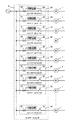
先ず、コントロールセンタの概念の一例を回路的に例示する図1、および複数の列盤の各々を構成するコントロールユニットの前面パネルに、負荷状態を表示する負荷状態監視画面表示装置、およびこの負荷状態監視画面表示装置の近傍に位置する異常表示装置を備えたコントロールセンタの外観の一例を概略的に例示する図2によって、コントロールユニットの概念を説明する。 First, FIG. 1 illustrating an example of the concept of a control center in circuit form, and a load state monitoring screen display device for displaying a load state on the front panel of a control unit constituting each of a plurality of rows, and the load state The concept of the control unit will be described with reference to FIG. 2 schematically illustrating an example of the appearance of a control center provided with an abnormality display device located in the vicinity of the monitoring screen display device .
図1および図2に一例を示してあるように、規模が比較的大きな工場などでは、多数のコンベアモータ、多数のポンプモータ、多数のファンモータ等の比較的容量の大きな多数のモータ1が設置され、これら多数のモータ負荷の負荷状態監視・制御は多数の列盤からなる大型のコントロールセンタ2で行われる。
As shown in FIG. 1 and FIG. 2, in a relatively large factory, a large number of
コントロールセンタ2は、例えばモータ負荷電流を検出する変流器等の負荷状態検出センサ21、モータ主回路を開閉する電磁接触器等のコンタクタ22、負荷状態検出センサ21の出力を入力しモータ負荷の負荷状態監視・制御(コンタクタ22によるモータ主回路の開閉を含む)を行うコントロールユニット23を含む多数の列盤24で構成されている。図2は、列盤24が12個あり、各列盤にコントロールユニット23が6個ある事例をしめしてある。
The control center 2 receives outputs of a load
各コントロールユニット23は、電子機器ユニット231を有しており、電子機器ユニット231は、負荷状態を表示する負荷状態監視画面表示装置2311および異常表示装置2312等を有している。換言すれば、コントロールユニット23は、負荷状態監視画面表示装置2311および異常表示装置2312等を有している。
Each
図2は、コントロールセンタ2の収納建屋A内の通路AAから最も遠い最奥の列盤の最も上のコントロールユニット23の電子機器ユニット231、負荷状態監視画面表示装置2311、および異常表示装置2312の符合を引き出し線で図示してあるが、コントロールユニット23については、電子機器ユニット、負荷状態監視画面表示装置、および異常表示装置は図から判別できるので、それらの符合の図示は省略してある。同様に、各コントロールユニット23も、図から判別できるので、通路AAから最も遠い最奥の列盤24だけに、各コントロールユニット 23の符合を図示し、他は図示省略してある。
FIG. 2 shows the
コントロールユニット23の電子機器ユニット231の部分の正面図である図3、およびコントロールユニット23の電子機器ユニット231の部分の平面図である図4に一例を図示してあるように、電子機器ユニット231の前面パネルには負荷状態監視画面表示装置2311の近傍に位置する異常表示装置2312以外に、対象モータ1(図1参照)のON−OFF(コンタクタ32(図1参照)の開閉)等の操作を行う操作ボタン2313、負荷状態の異常レベルの設定等を行う設定操作子2314等が設けられている。
As shown in FIG. 3 which is a front view of the
異常表示装置2312は後に詳述するが、その前部の表示用の例えば光透過性プラスチックで形成されたレンズ23121は、例えば前記ON表示用のレンズ231211、前記OFFの表示用のレンズ231212、負荷状態の異常の表示用のレンズ231213、コントロールユニット23内(電子機器ユニット231内を含む)の動作エラーの表示用のレンズ231214で構成されている。また、これらレンズ231211,231212,231213,231214は、図示の例では、上下に所定間隔毎に一列に配設されており、何れも、電子機器ユニット231の前面(つまりコントロールユニット23の前面)から前方に所定長だけ突出している(図4参照)。
The
コントロールユニット23の電子機器ユニット231の内部構成は、図3のV−V線における断面を矢印方向に見た拡大断面図である図4に一例を例示してあるように、前面パネル2313、裏面パネル2314、電源回路部2315、I/O回路基板2316、制御回路基板2317、表示回路基板2318、コネクタ2319,2320,2321,2322,2323、液晶表示パネル2324、液晶表示パネルのバックライト2325、透明窓板2326、ヒンジ2327を備えた構成としてある。
The internal configuration of the
前記前面パネル2313は、コントロールユニット23の前面パネルを構成しており、光不透過性の樹脂、他で形成されている。
The
前記裏面パネル2314は、樹脂、他で形成されており、その裏面側には、コントロールユニット23に内蔵の前記負荷状態検出センサ21、前記コンタクタ22等が配設されている。
The
前記電源回路部2315は、前記各基板2316,2317,2318に直流電源を供給する電源回路であり、降圧トランス(図示省略)で所定電圧に降圧された交流を取り込み、内蔵のブリッジ回路(交直変換回路)で交流を直流に変換した後、当該ブリッジ回路の直流出力を電解コンデンサ等の内蔵の平滑コンデンサで平滑する機能を有しており、平滑した直流を前記各基板2316,2317,2318に供給するものである。
The power
前記I/O回路基板2316は、いわゆる入出力回路が形成された基板であり、前記負荷状態検出センサで検出された負荷状態情報信号(アナログ信号)を入力し、前記制御回路基板2317に、デジタルの負荷状態情報信号を出力するものである。
The I /
前記制御回路基板2317は、入力したデジタルの負荷状態情報信号に基づき前記負荷状態監視画面表示装置2311および前記異常表示装置2312に、各表示装置2311,2312に必要な表示制御信号を出力するものである。
The
前記表示回路基板2318は、前記制御回路基板2317から前記表示制御信号を入力し、当該表示制御信号に基づいて、前記ON、前記OFF、前記負荷状態の異常、前記動作エラーの表示動作信号を、前記異常表示装置2312に出力し、前記負荷状態の計測値等の表示動作信号を、前記負荷状態監視画面表示装置2311に出力する。
The
前記コネクタ2319は、前記負荷状態検出センサ21の検出出力信号線と前記I/O回路基板2316の入力端子とを接続するものである。
前記コネクタ2320,2321は、前記I/O回路基板2316の出力端子と前記制御回路基板2317の入力端子とを接続するものであり、ハーネスを使用することなく両基板の入出力端子間を接続することからボード・ツー・ボード・コネクタとも呼称されている。
前記コネクタ2322は、前記電源回路部2315に設けられ、交流電源(図示省略してある降圧変圧器の2次出力)を取り込む端子である。
前記コネクタ2323は、前記制御回路基板2317の出力端子と前記表示回路基板2318の入力端子とを接続するものであり、前記ボード・ツー・ボード・コネクタである。The
The
The
The
前記液晶表示パネル2324は、液晶を使った表示パネルであり、前記表示回路基板2318からの表示動作信号に基づいて前記負荷状態の計測値等の表示を行うものである。
The liquid
前記液晶表示パネルのバックライト2325は、前記液晶表示パネル2324の裏面側から前記液晶表示パネル2324に向けて光を放射する光源であり、液晶表示パネル2324の表示を鮮明にするものである。
なお、前記バックライト2325の光強度および/または前記液晶表示パネル2324の背景色を、前記表示回路基板2318からの表示動作信号に基づいて、前記モータ負荷の定常時に比べ異常時の方が明るくなるようにすれば、多数の列盤の場合でも視認し易くなる。The
It should be noted that the light intensity of the
前記透明窓板2326は、前記液晶表示パネル2324の前面を保護するものであり、前記前面パネル2313の開口に取り付けられている。
The
前記ヒンジ2327は、固定部2328に設けられ、前記前面パネル2313の裏面側の片端2313A、および前記裏面パネル2314の前記前面パネル2313の片端2313Aと同じ側の片端2314Aの双方が枢着されており、この枢着により、前記前面パネル2313および前記裏面パネル2314は、何れも、互いに個別に、前記ヒンジ2327を軸心として矢印A方向に回動できる、即ち、片開きで開閉できる。
The
前記ヒンジ2327を軸心として前記前面パネル2313を矢印A方向に回動する(開く)と、前記前面パネル2313、前記表示用のレンズ23121、および前記透明窓板2326が、前記ヒンジ2327を軸心として前記矢印A方向に一体をなして回動して開き、その結果、外部に露出した状態となった前記電源回路部2315、前記I/O回路基板2316、前記制御回路基板2317、前記表示回路基板2318、前記コネクタ2319,2320,2321,2322,2323、前記液晶表示パネル2324、および前記液晶表示パネルのバックライト2325等の保守点検ができる。
When the
また、前記ヒンジ2327を軸心として前記裏面パネル2314を矢印A1方向に回動する(開く)と、前記裏面パネル2314、前記電源回路部2315、前記I/O回路基板2316、前記制御回路基板2317、前記表示回路基板2318、前記コネクタ2319,2320,2321,2322,2323、前記液晶表示パネル2324、および前記液晶表示パネルのバックライト2325、前記ヒンジ2327を軸心として前記矢印A2方向に一体をなして回動して開き、その結果、外部に露出した状態となった前記負荷状態検出センサ21、コンタクタ22等の保守点検ができる。
Further, when the
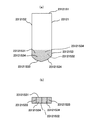
ここで、前記異常表示装置2312の構造を、図6〜図9により詳細に説明する。図6は図5における前記異常表示装置2312の部分を更に拡大して示す拡大断面図、図7は前記レンズ23121の光伝達部を囲繞する部分を裏側から見た外観図、図8は前記光源23122を前面側から見た外観図、図9は前記レンズ23121,231211,231212,231213,231214の斜視図である。
Here, the structure of the
前記前面パネル2313の、前記負荷状態監視画面表示装置2311の近傍で、前記液晶表示パネル2324、前記液晶表示パネルのバックライト2325、および前記透明窓板2326から所定距離離れた位置に、前記液晶表示パネル2324、前記液晶表示パネルのバックライト2325、および前記透明窓板2326の重積方向と平行をなして、前記前面パネル2313から裏面側に一体に突出する筒状部23131が形成されている。
The liquid crystal display is positioned at a predetermined distance from the liquid
前記筒状部23131には、それぞれ前記前面パネル2313の裏面側から前面側に貫通し互いに平行をなして延在する4個(つまり複数個)のレンズ取付用貫通孔231311,231312,231313,231314が設けられている。これらレンズ取付用貫通孔231311,231312,231313,231314は何れも、裏側から見た形状は図示のように、長方形等の矩形であり、各々の大きさは同じである。
換言すれば、前記筒状部23131は、前面パネル2313を前後に貫通する複数個のレンズ取付用貫通孔231311,231312,231313,231314を有していると言え、また、観点を変えれば、レンズ取付用貫通孔231311を有する筒状部とレンズ取付用貫通孔231312を有する筒状部とレンズ取付用貫通孔231313を有する筒状部とレンズ取付用貫通孔231314を有する筒状部とが一体に形成された筒状部とも言える。The
In other words, the
前記レンズ取付用貫通孔231311に前記ON表示用のレンズ231211が、前記レンズ取付用貫通孔231312に前記OFFの表示用のレンズ231212が、前記レンズ取付用貫通孔231313に前記負荷状態の異常の表示用のレンズ231213が、前記レンズ取付用貫通孔231314に前記動作エラーの表示用のレンズ231214が、それぞれ挿入されて、対応レンズ取付用貫通孔内に固定されている。
The
また、前記レンズ231211,231212,231213,231214の各々の受光面23121S1は、図示のように、前記筒状部23131の内端面23131Aより前面側に位置し、前記レンズ231211,231212,231213,231214の各々の受光面23121S1と前記筒状部23131の内端面23131Aとの間には、窪み23131Bが形成されている。
Further, as shown in the drawing, the light receiving surfaces 23121S1 of the
前記光源23122は、前記ON表示用のレンズ231211に対向したON表示用のLED231221、前記OFFの表示用のレンズ231212に対向したOFF表示用のLED231222、前記負荷状態の異常の表示用のレンズ231213に対向した負荷状態異常表示用のLED231223、ユニット内動作エラーの表示用のレンズ231214に対向したユニット内動作エラー表示用のLED231224で構成されている。
The
図示の例では、前記ON表示用のLED231221は所定間隔で配設された緑G、赤R、緑Gの3個のLEDで構成され、前記OFF表示用のLED231222は所定間隔で配設された緑G、赤R、緑Gの3個のLEDで構成され、前記負荷状態異常表示用のLED231223は所定間隔で配設された橙Oの2個のLEDで構成され、前記ユニット内動作エラー表示用のLED231224は、赤Rの1個のLEDで構成されている。
In the illustrated example, the
前記ON時には前記赤Rの前記ON表示用のLED231221が、前記OFF時には前記緑Gの前記OFF表示用のLED231222が、前記負荷状態異常時には前記橙Oの2個の前記負荷状態異常表示用のLED231223が、前記ユニット内動作エラー時には前記赤Rの前記ユニット内動作エラー表示用のLED231224が、それぞれ前記表示回路基板2318からの表示駆動信号によって発光する。
The red R ON-
前記ON表示用のLED231221は、対向する前記ON表示用のレンズ231211に対応の前記窪み23131B内に前面側の先端の光放射面23122Aが位置し、前記OFF表示用のLED231222は、対向する前記OFFの表示用のレンズ231212に対応の前記窪み23131B内に前面側の先端の光放射面23122Aが位置し、前記負荷状態異常表示用のLED231223は、対向する前記負荷状態の異常表示用のレンズ231213に対応の前記窪み23131B内に前面側の先端の光放射面23122Aが位置し、前記ユニット内動作エラー表示用のLED231224は、対向する前記ユニット内動作エラーの表示用のレンズ231214に対応の前記窪み23131B内に前面側の先端の光放射面23122Aが位置している。つまり、前記光源23122の前面側の光放射面23122Aが光不透過性の前記筒状部23131内に位置しており、前記光放射面23122Aから放射された光の拡散
が前記筒状部23131で防止される構造としてある。The
前記光源23122の前記光放射面23122Aと前記表示用のレンズ23121の前記受光面23121S1との間には所定長のギャップgが確保されており、前記光源23122の前記光放射面23122Aと前記表示用のレンズ23121の前記受光面23121S1とが当接するのを防止する構造としてある。
A gap g of a predetermined length is secured between the light emitting surface 23122A of the
前記表示用のレンズ23121、つまり、前記ON表示用のレンズ231211、前記OFFの表示用のレンズ231212、前記負荷状態の異常の表示用のレンズ231213、前記動作エラーの表示用のレンズ231214は、何れも、前記受光面23121S1に前記光源23122から入射した光を伝達する柱状の光伝達部23121S2と前記前面パネル2313から外部に突出し前記光伝達部23121S2によって伝達された光を放射する光放射部23121S3とを有している。
The
前記光放射部23121S3は、図9に図示のように、先端部がほぼアーチ形状をなすほぼ扁平な第1の側面23121S31と、この第1の側面23121S31とほぼ平行をなし先端部がほぼアーチ形状をなすほぼ扁平な第2の側面23121S32と、前記第1の側面23121S31の周縁部と前記第2の側面23121S32の周縁部とに跨ってほぼアーチ形状に延在する前面23121S33とを有し、前記第1の側面23121S31、前記第2の側面23121S32、および前記前面23121S33、の何れにも、粗面化加工23121S34が施されている。なお、粗面化加工とは、シボ加工、ヤスリ(サンドペーパ)加工、レーザによる表面加工など、いわゆる粗面化加工である。 As shown in FIG. 9, the light emitting portion 23121S3 has a substantially flat first side surface 23121S31 having a substantially arched tip portion, and is substantially parallel to the first side surface 23121S31 and has a substantially arched shape. A substantially flat second side surface 23121S32, and a front surface 23121S33 extending substantially in an arch shape across the peripheral edge portion of the first side surface 23121S31 and the peripheral edge portion of the second side surface 23121S32, The first side surface 23121S31, the second side surface 23121S32, and the front surface 23121S33 are all roughened 23121S34. The roughening process is a so-called roughening process such as a texture process, a file (sandpaper) process, or a surface process using a laser.
前記光放射部23121S3を、図9に図示のように、先端部がほぼアーチ形状をなすほぼ扁平な第1の側面23121S31と、この第1の側面23121S31とほぼ平行をなし先端部がほぼアーチ形状をなすほぼ扁平な第2の側面23121S32と、前記第1の側面23121S31の周縁部と前記第2の側面23121S32の周縁部とに跨ってほぼアーチ形状に延在する前面23121S33とで構成し、前記第1の側面23121S31、前記第2の側面23121S32、および前記前面23121S33、の何れにも、粗面化加工23121S34を施した場合、矢印a,b,c,d,eの方向、即ち、上から見ても、下から見ても、左右の何れから見ても、前方から見ても、前記光放射部23121S3から放射される光が強く、試作試験の結果、例えば前記光放射部23121S3を半球状にしてその全面に粗面化加工を施した場合と比べると、視認性が可成り向上した。従って、多数のモータ負荷の負荷状態監視・制御を行う多数の列盤からなる大型コントロールセンタ(図2参照)において、列盤24,24,・・・を構成するコントロールユニット23,23,・・・の異常表示装置2312は、監視員が当該列盤に近づいて目視確認しなくても、工場内通路AAなど比較的遠くの位置から視認できる。
As shown in FIG. 9, the light emitting portion 23121S3 includes a first flat side surface 23121S31 having a substantially arch-shaped tip portion, and substantially parallel to the first side surface 23121S31 and a tip portion having a substantially arched shape. A substantially flat second side surface 23121S32, and a front surface 23121S33 extending substantially in an arch shape across the peripheral edge portion of the first side surface 23121S31 and the peripheral edge portion of the second side surface 23121S32, When roughening 23121S34 is applied to any of the first side surface 23121S31, the second side surface 23121S32, and the front surface 23121S33, the directions of arrows a, b, c, d, e, that is, from above The light emitted from the light emitting unit 23121S3 is strong, whether viewed from below, viewed from the left or right, or viewed from the front. As a result of the trial test, for example, the light emitting unit 23121S3 is hemispherical. Compared with the case where the entire surface is roughened, the visibility is significantly improved. It was. Therefore, in a large control center (see FIG. 2) composed of a large number of rows for monitoring and controlling the load states of a large number of motor loads, the
実施の形態2.
この発明の実施の形態2として、LEDの各種配置を図10に例示する。Embodiment 2. FIG.
As a second embodiment of the present invention, various LED arrangements are illustrated in FIG.
実施の形態1において説明した前記ON表示用のLED231221、OFF表示用のLED231222、負荷状態異常表示用のLED231223、ユニット内動作エラー表示用のLED231224の何れも、実施の形態1に例示の配置に限られるものでなく、図10の(a)〜(e)に例示のような各種の配置としてもよい。なお、図10において、Gは緑色発光のLED、Rは赤色発光のLEDであり、何れも一つのレンズに対し個数が多いほど輝度が増し、実施の形態1に示す粗面化された各面での放射光による全方向からの視認性が向上する。
Any of the
実施の形態3.
本実施の形態3は、図11(a)(b)に例示のように、表示用のレンズ23121の粗面化された光放射部23121S3における第1の側面23121S31、第2の側面23121S32の平面形状を台形状の5角形(先端部の形状は3角形)とし、前記第1の側面23121S31の周縁部と前記第2の側面23121S32の周縁部とに跨って延在する前面23121S33の平面形状も、前記第1の側面23121S31及び前記第2の側面23121S32の平面形状に合わせて、台形状の5角形(先端部の形状は3角形)とした事例である。
In the third embodiment, as illustrated in FIGS. 11A and 11B, the planes of the first side surface 23121S31 and the second side surface 23121S32 in the light emitting portion 23121S3 roughened of the
実施の形態4.
本実施の形態3は、図12(a)(b)に例示のように、表示用のレンズ23121の粗面化された光放射部23121S3における第1の側面23121S31、第2の側面23121S32の平面形状を台形状の6角形(先端部の形状は4角形)とし、前記第1の側面23121S31の周縁部と前記第2の側面23121S32の周縁部とに跨って延在する前面23121S33の平面形状も、前記第1の側面23121S31及び前記第2の側面23121S32の平面形状に合わせて、台形状の6角形(先端部の形状は4角形)とした事例である。Embodiment 4 FIG.
In the third embodiment, as illustrated in FIGS. 12A and 12B, the planes of the first side surface 23121S31 and the second side surface 23121S32 in the roughened light emitting portion 23121S3 of the
実施の形態3及び4の場合も、前述の実施の形態1における図9に図示の事例の場合と同様に、上から見ても、下から見ても、左右の何れから見ても、前方から見ても、前記光放射部23121S3から放射される光が強く、試作試験の結果、例えば前記光放射部23121S3を半球状にしてその全面に粗面化加工を施した場合と比べると、視認性が可成り向上した。従って、多数のモータ負荷の負荷状態監視・制御を行う多数の列盤からなる大型コントロールセンタ(図2参照)において、列盤24,24,・・・を構成するコントロールユニット23,23,・・・の異常表示装置2312は、監視員が当該列盤に近づいて目視確認しなくても、工場内通路AAなど比較的遠くの位置から視認できる。
In the case of the third and fourth embodiments, as in the case of the example shown in FIG. 9 in the first embodiment described above, it can be seen from the top, from the bottom, and from the left and right. Even when viewed from the viewpoint, the light emitted from the light emitting portion 23121S3 is strong, and as a result of the prototype test, for example, compared with the case where the light emitting portion 23121S3 is hemispherical and the entire surface thereof is roughened, The sex improved considerably. Therefore, in a large control center (see FIG. 2) composed of a large number of rows for monitoring and controlling the load states of a large number of motor loads, the
なお、本件出願の請求の範囲、明細書、要約においては、実施の形態3及び4の場合における形状(平面形状を台形状の5角形(先端部の形状は3角形)、平面形状を台形状の6角形(先端部の形状は4角形))を含めて「ほぼアーチ形状」と表現してある。
In addition, in the claims, the specification, and the summary of the present application, the shape in the case of
なお、図1〜図12の各図中、同一符合は同一または相当部分を示す。 In addition, in each figure of FIGS. 1-12, the same code | symbol shows the same or an equivalent part.
なお、前述の説明および前述の各図からも明白なように、本実施の形態1には、以下のような技術的特徴がある。 As is clear from the above description and the respective drawings, the first embodiment has the following technical features.
特徴点1:複数の列盤の各々を構成するコントロールユニットの前面パネルに、負荷状態を表示する負荷状態監視画面表示装置、およびこの負荷状態監視画面表示装置の近傍に位置する異常表示装置を備えたコントロールセンタにおいて、
前記異常表示装置が、前記前面パネル内側に配設された光源、および前記前面パネルを貫通し前記光源が発生する光を入射する受光面とこの受光面に入射した光を伝達する柱状の光伝達部と前記前面パネルから外部に突出し前記光伝達部によって伝達された光を放射する光放射部とを有するレンズで構成され、
前記光放射部は、先端部がほぼアーチ形状をなすほぼ扁平な第1の側面とこの第1の側面とほぼ平行をなし先端部がほぼアーチ形状をなすほぼ扁平な第2の側面と前記第1の側面の周縁部と前記第2の側面の周縁部とに跨ってほぼアーチ形状に延在する前面とを有し、 前記第1の側面、前記第2の側面、および前記前面の何れにも粗面化加工が施されていることを特徴とするコントロールセンタ。Feature 1: A load state monitoring screen display device for displaying a load state and an abnormality display device located in the vicinity of the load state monitoring screen display device are provided on the front panel of the control unit constituting each of the plurality of rows. In the control center
The abnormality display device includes a light source disposed inside the front panel, a light receiving surface that passes through the front panel and receives light generated by the light source, and a columnar light transmission that transmits light incident on the light receiving surface. And a lens having a light emitting portion that projects outward from the front panel and emits light transmitted by the light transmitting portion,
The light emitting portion includes a substantially flat first side surface having a substantially arch-shaped tip portion, a substantially flat second side surface substantially parallel to the first side surface and a substantially arch-shaped tip portion, and the first side surface. A front surface extending substantially in an arch shape across a peripheral edge portion of one side surface and a peripheral edge portion of the second side surface, and any one of the first side surface, the second side surface, and the front surface The control center is also characterized by being roughened.
特徴点2:特徴点1に記載のコントロールセンタにおいて、前記レンズおよび前記光源の対が少なくとも2対設けられ、その1対は負荷状態の異常を表示し、他の一対は前記コントロールユニット内の動作エラーを表示することを特徴とするコントロールセンタ。
Feature point 2: In the control center described in
特徴点3:特徴点2に記載のコントロールセンタにおいて、前記各対のレンズは並設され、前記各対の光源は並設されていることを特徴とするコントロールセンタ。 Feature point 3: The control center according to feature point 2, wherein each pair of lenses is arranged side by side, and each pair of light sources is arranged side by side.
特徴点4:特徴点1〜3の何れか一に記載のコントロールセンタにおいて、前記前面パネルに設けられたレンズ取付用貫通孔内に前記レンズが取り付けられ、前記コントロールユニット内に設けられ前記負荷状態監視画面表示装置の表示制御および前記光源の発光制御を行う表示制御基板に前記光源が取り付けられていることを特徴とするコントロールセンタ。
Feature point 4: In the control center according to any one of
特徴点5:特徴点1〜4の何れか一に記載のコントロールセンタにおいて、前記前面パネルの少なくとも前記光伝達部を囲繞する部分は光不透過性樹脂で形成され、前記レンズは光透過性プラスチックで形成され、前記光源はLEDであることを特徴とするコントロールセンタ。
Feature point 5: In the control center according to any one of
特徴点6:特徴点4または特徴点5に記載のコントロールセンタにおいて、前記前面パネルに一体に設けられた筒状部内に前記レンズ取付用貫通孔が形成され、前記筒状部の内端面より前面側に前記レンズの前記受光面が位置し、前記光源の前面側の光放射面が前記筒状部内に位置していることを特徴とするコントロールセンタ。 Feature point 6: In the control center according to feature point 4 or feature point 5, the lens mounting through-hole is formed in a cylindrical portion integrally provided in the front panel, and the front surface is located in front of the inner end surface of the cylindrical portion. The control center, wherein the light receiving surface of the lens is located on the side, and a light emitting surface on the front side of the light source is located in the cylindrical portion.
特徴点7:特徴点6に記載のコントロールセンタにおいて、前記レンズの前記受光面と前記光源の前記光放射面との間に所定長のギャップが形成されていることを特徴とするコントロールセンタ。
Feature point 7: The control center according to
特徴点8:特徴点4〜7の何れか一に記載のコントロールセンタにおいて、 前記前面パネルは、前記表示制御基板に対して可枢動であることを特徴とするコントロールセンタ。 Feature point 8: The control center according to any one of feature points 4 to 7, wherein the front panel is pivotable with respect to the display control board.
特徴点9:各列盤の各コントロールユニットの全てが、前記特徴点1〜8の少なくとも一つの特徴構成を有していることを特徴とするコントロールセンタ。 Feature point 9: A control center characterized in that all the control units of each row board have at least one feature configuration of the feature points 1 to 8.
Claims (8)
前記各コントロールユニットの前記異常表示装置が、前記前面パネル内側に配設された光源、および前記前面パネルを貫通し前記光源が発生する光を入射する受光面とこの受光面に入射した光を伝達する柱状の光伝達部と前記前面パネルから外部に突出し前記光伝達部によって伝達された光を放射する光放射部とを有するレンズで構成され、
前記前面パネルに一体に設けられた光不透過性の筒状部内にレンズ取付用貫通孔が形成され、
前記光不透過性の筒状部の内端面より前面側に前記レンズの前記受光面が位置し、
前記光源の前面側の光放射面が前記光不透過性の筒状部内に位置し、
前記光不透過性の筒状部内の前記レンズ取付用貫通孔内に前記レンズの光伝達部が配設され、
前記前面パネルから外部に突出した前記光放射部は、先端部がほぼアーチ形状をなすほぼ扁平な第1の側面とこの第1の側面とほぼ並行をなし先端部がほぼアーチ形状をなすほぼ扁平な第2の側面と前記第1の側面の周縁部と前記第2の側面の周縁部とに跨ってほぼアーチ形状に延在する前面とを有し、
前記光放射部の、前記第1の側面、前記第2の側面、および前記前面の何れにも粗面化加工が施され、
前記光放射部が上下に複数個配列されている
ことを特徴とするコントロールセンタ。 Provided on the front panel of each of the plurality of control units constituting each of the plurality of rows is a load state monitoring screen display device for displaying a load state, and an abnormality display device located in the vicinity of the load state monitoring screen display device In the control center
The abnormality display device of each control unit transmits a light source disposed inside the front panel, a light receiving surface that passes through the front panel and receives light generated by the light source, and light incident on the light receiving surface. A lens-shaped light transmitting portion and a lens having a light emitting portion that projects outward from the front panel and emits light transmitted by the light transmitting portion,
A lens mounting through-hole is formed in a light-impermeable cylindrical portion provided integrally with the front panel,
The light receiving surface of the lens is located on the front side from the inner end surface of the light-impermeable cylindrical portion,
The light emitting surface on the front side of the light source is located in the light-impermeable cylindrical portion,
A light transmitting portion of the lens is disposed in the lens mounting through-hole in the light-impermeable cylindrical portion;
The light emitting portion projecting outward from the front panel has a substantially flat first side surface having a substantially arched tip portion and a substantially flat first surface substantially parallel to the first side surface and a substantially arched tip portion. A second side surface, a front surface extending substantially in an arch shape across a peripheral edge portion of the first side surface and a peripheral edge portion of the second side surface,
A roughening process is performed on any of the first side surface, the second side surface, and the front surface of the light emitting portion ,
A control center, wherein a plurality of the light emitting portions are arranged vertically .
前記光放射部の前記ほぼアーチ形状に延在する前記前面が上下方向に延在する面を有しているThe front surface of the light emitting portion extending in the substantially arch shape has a surface extending in the vertical direction.
ことを特徴とするコントロールセンタ。Control center characterized by that.
前記各対のレンズは並設され、前記各対の光源は並設されている
ことを特徴とするコントロールセンタ。In the control center according to claim 1 or 2 ,
The control center, wherein each pair of lenses is arranged side by side, and each pair of light sources is arranged side by side.
前記コントロールユニット内に設けられ前記負荷状態監視画面の表示制御および前記光源の発光制御を行う表示制御基板に前記光源が取り付けられている
ことを特徴とするコントロールセンタ。In the control center according to any one of claims 1 to 3 ,
Control center, characterized in that said light source to the display control board provided in front Symbol control the unit controlling the display and the emission control of the light source of the load state monitoring screen is attached.
前記レンズは光透過性プラスチックで形成され、
前記光源はLEDである
ことを特徴とするコントロールセンタ。In the control center according to any one of claims 1 to 4 ,
Before SL lens is formed of a light transmitting plastic,
The control center, wherein the light source is an LED.
前記レンズの前記受光面と前記光源の前記光放射面との間に所定長のギャップが形成されている
ことを特徴とするコントロールセンタ。In the control center according to claim 5 ,
A control center, wherein a gap having a predetermined length is formed between the light receiving surface of the lens and the light emitting surface of the light source.
前記光放射部の前記前面の前記ほぼアーチ形状が三角形であるThe substantially arch shape of the front surface of the light emitting portion is a triangle.
ことを特徴とするコントロールセンタ。Control center characterized by that.
前記前面パネルは、前記表示制御基板に対して可枢動である
ことを特徴とするコントロールセンタ。In the control center according to any one of claims 4 to 7,
The control center, wherein the front panel is pivotable with respect to the display control board.
Priority Applications (1)
| Application Number | Priority Date | Filing Date | Title |
|---|---|---|---|
| JP2009553330A JP5008729B2 (en) | 2008-02-14 | 2008-07-14 | Control center |
Applications Claiming Priority (4)
| Application Number | Priority Date | Filing Date | Title |
|---|---|---|---|
| JP2008033229 | 2008-02-14 | ||
| JP2008033229 | 2008-02-14 | ||
| JP2009553330A JP5008729B2 (en) | 2008-02-14 | 2008-07-14 | Control center |
| PCT/JP2008/062697 WO2009101716A1 (en) | 2008-02-14 | 2008-07-14 | Control center |
Publications (2)
| Publication Number | Publication Date |
|---|---|
| JPWO2009101716A1 JPWO2009101716A1 (en) | 2011-06-02 |
| JP5008729B2 true JP5008729B2 (en) | 2012-08-22 |
Family
ID=40956760
Family Applications (1)
| Application Number | Title | Priority Date | Filing Date |
|---|---|---|---|
| JP2009553330A Active JP5008729B2 (en) | 2008-02-14 | 2008-07-14 | Control center |
Country Status (5)
| Country | Link |
|---|---|
| JP (1) | JP5008729B2 (en) |
| KR (1) | KR101193253B1 (en) |
| CN (1) | CN101953042B (en) |
| TW (1) | TW200935695A (en) |
| WO (1) | WO2009101716A1 (en) |
Families Citing this family (2)
| Publication number | Priority date | Publication date | Assignee | Title |
|---|---|---|---|---|
| WO2013005151A1 (en) * | 2011-07-05 | 2013-01-10 | Koninklijke Philips Electronics N.V. | Lighting module |
| WO2017029706A1 (en) * | 2015-08-18 | 2017-02-23 | 三菱電機株式会社 | Display control system and control center using same, specific position navigation system, and information display system for panel equipment |
Citations (10)
| Publication number | Priority date | Publication date | Assignee | Title |
|---|---|---|---|---|
| JPS58155712A (en) * | 1982-03-12 | 1983-09-16 | Hitachi Ltd | Molded ignition coil |
| JPS6168437A (en) * | 1984-09-10 | 1986-04-08 | ザ・グツドイヤー・タイヤ・アンド・ラバー・カンパニー | Manufacture of hydroxyanisole and alkylated hydroxyanisole |
| JPS6336105A (en) * | 1986-07-30 | 1988-02-16 | Nippon Kokan Kk <Nkk> | Film thickness measuring instrument |
| JPS63102122A (en) * | 1986-10-17 | 1988-05-07 | 松下電器産業株式会社 | Illumination type panel |
| JPH01176327A (en) * | 1987-12-29 | 1989-07-12 | Matsushita Electric Ind Co Ltd | Production of perpendicular magnetic recording medium |
| JPH03138733A (en) * | 1989-10-25 | 1991-06-13 | Mitsubishi Electric Corp | Controller with operation error display device |
| JPH075425A (en) * | 1993-06-14 | 1995-01-10 | Mitsubishi Electric Corp | Motor controller |
| JPH0756528A (en) * | 1993-08-17 | 1995-03-03 | Mitsubishi Electric Corp | Display device |
| JP2000348517A (en) * | 1999-06-07 | 2000-12-15 | Stanley Electric Co Ltd | Light emitting device |
| JP2004230563A (en) * | 2003-01-28 | 2004-08-19 | Nippon Seiki Co Ltd | Resin molding |
Family Cites Families (4)
| Publication number | Priority date | Publication date | Assignee | Title |
|---|---|---|---|---|
| JPS58155712U (en) * | 1982-04-14 | 1983-10-18 | カシオ計算機株式会社 | Display element mounting structure |
| JPH0247543Y2 (en) * | 1984-10-12 | 1990-12-13 | ||
| JPH0317524Y2 (en) * | 1986-08-25 | 1991-04-12 | ||
| JPH01176327U (en) * | 1988-06-02 | 1989-12-15 |
-
2008
- 2008-07-14 WO PCT/JP2008/062697 patent/WO2009101716A1/en active Application Filing
- 2008-07-14 JP JP2009553330A patent/JP5008729B2/en active Active
- 2008-07-14 CN CN200880126904.1A patent/CN101953042B/en active Active
- 2008-07-14 KR KR1020107020077A patent/KR101193253B1/en active IP Right Grant
- 2008-07-21 TW TW97127590A patent/TW200935695A/en unknown
Patent Citations (10)
| Publication number | Priority date | Publication date | Assignee | Title |
|---|---|---|---|---|
| JPS58155712A (en) * | 1982-03-12 | 1983-09-16 | Hitachi Ltd | Molded ignition coil |
| JPS6168437A (en) * | 1984-09-10 | 1986-04-08 | ザ・グツドイヤー・タイヤ・アンド・ラバー・カンパニー | Manufacture of hydroxyanisole and alkylated hydroxyanisole |
| JPS6336105A (en) * | 1986-07-30 | 1988-02-16 | Nippon Kokan Kk <Nkk> | Film thickness measuring instrument |
| JPS63102122A (en) * | 1986-10-17 | 1988-05-07 | 松下電器産業株式会社 | Illumination type panel |
| JPH01176327A (en) * | 1987-12-29 | 1989-07-12 | Matsushita Electric Ind Co Ltd | Production of perpendicular magnetic recording medium |
| JPH03138733A (en) * | 1989-10-25 | 1991-06-13 | Mitsubishi Electric Corp | Controller with operation error display device |
| JPH075425A (en) * | 1993-06-14 | 1995-01-10 | Mitsubishi Electric Corp | Motor controller |
| JPH0756528A (en) * | 1993-08-17 | 1995-03-03 | Mitsubishi Electric Corp | Display device |
| JP2000348517A (en) * | 1999-06-07 | 2000-12-15 | Stanley Electric Co Ltd | Light emitting device |
| JP2004230563A (en) * | 2003-01-28 | 2004-08-19 | Nippon Seiki Co Ltd | Resin molding |
Also Published As
| Publication number | Publication date |
|---|---|
| WO2009101716A1 (en) | 2009-08-20 |
| KR101193253B1 (en) | 2012-10-19 |
| CN101953042A (en) | 2011-01-19 |
| JPWO2009101716A1 (en) | 2011-06-02 |
| TW200935695A (en) | 2009-08-16 |
| CN101953042B (en) | 2016-11-02 |
| TWI376854B (en) | 2012-11-11 |
| KR20100107526A (en) | 2010-10-05 |
Similar Documents
| Publication | Publication Date | Title |
|---|---|---|
| EP3037080B1 (en) | Multi-alert lights for hospital bed | |
| KR102573208B1 (en) | Display panel | |
| KR19990083648A (en) | Fault detection circuit of all-optical display device and display state detection method using same | |
| TW201314292A (en) | A mother substrate including detecting wires on array and a method for detecting the same | |
| JP5008729B2 (en) | Control center | |
| US20140013093A1 (en) | Pinout adjustment responsive to system orientation | |
| JP5340442B2 (en) | Control center | |
| CN102662258B (en) | Detection method and device of backlight module | |
| JP2010098209A (en) | Broken light emitting element detection system | |
| KR20120006316A (en) | Led module tester | |
| KR101474740B1 (en) | Device for testing connection between PC card and printed cricuit board | |
| JP5647866B2 (en) | Tunnel lighting maintenance management system | |
| JP5775046B2 (en) | Display device | |
| JP2012099339A (en) | Electric control device | |
| CN101881660B (en) | Detecting jig and method of surface brightness of product | |
| JP6347467B2 (en) | TV equipment | |
| US20220137120A1 (en) | System and method for testing optical receivers | |
| KR20220117417A (en) | Inspection apparatus for inspecting display module | |
| JP2016218380A (en) | Display device | |
| KR20230089895A (en) | Monitoring system of led display device based on big data using control signal | |
| JPH05216432A (en) | Display controller | |
| JP2016012167A (en) | Display control system and control center using the same | |
| JP2008084780A (en) | Emergency lighting system | |
| JP2000172576A (en) | I/o port diagnostic circuit in disk array controller | |
| JP2017211261A (en) | Color tone inspection device and color tone inspection method |
Legal Events
| Date | Code | Title | Description |
|---|---|---|---|
| A131 | Notification of reasons for refusal |
Free format text: JAPANESE INTERMEDIATE CODE: A131 Effective date: 20120207 |
|
| A521 | Request for written amendment filed |
Free format text: JAPANESE INTERMEDIATE CODE: A523 Effective date: 20120330 |
|
| TRDD | Decision of grant or rejection written | ||
| A01 | Written decision to grant a patent or to grant a registration (utility model) |
Free format text: JAPANESE INTERMEDIATE CODE: A01 Effective date: 20120515 |
|
| A01 | Written decision to grant a patent or to grant a registration (utility model) |
Free format text: JAPANESE INTERMEDIATE CODE: A01 |
|
| A61 | First payment of annual fees (during grant procedure) |
Free format text: JAPANESE INTERMEDIATE CODE: A61 Effective date: 20120529 |
|
| R151 | Written notification of patent or utility model registration |
Ref document number: 5008729 Country of ref document: JP Free format text: JAPANESE INTERMEDIATE CODE: R151 |
|
| FPAY | Renewal fee payment (event date is renewal date of database) |
Free format text: PAYMENT UNTIL: 20150608 Year of fee payment: 3 |
|
| R250 | Receipt of annual fees |
Free format text: JAPANESE INTERMEDIATE CODE: R250 |
|
| R250 | Receipt of annual fees |
Free format text: JAPANESE INTERMEDIATE CODE: R250 |
|
| R250 | Receipt of annual fees |
Free format text: JAPANESE INTERMEDIATE CODE: R250 |
|
| R250 | Receipt of annual fees |
Free format text: JAPANESE INTERMEDIATE CODE: R250 |
|
| R250 | Receipt of annual fees |
Free format text: JAPANESE INTERMEDIATE CODE: R250 |
|
| R250 | Receipt of annual fees |
Free format text: JAPANESE INTERMEDIATE CODE: R250 |
|
| R250 | Receipt of annual fees |
Free format text: JAPANESE INTERMEDIATE CODE: R250 |
|
| R250 | Receipt of annual fees |
Free format text: JAPANESE INTERMEDIATE CODE: R250 |