JP5008469B2 - Game system, management device and slot machine - Google Patents
Game system, management device and slot machine Download PDFInfo
- Publication number
- JP5008469B2 JP5008469B2 JP2007158696A JP2007158696A JP5008469B2 JP 5008469 B2 JP5008469 B2 JP 5008469B2 JP 2007158696 A JP2007158696 A JP 2007158696A JP 2007158696 A JP2007158696 A JP 2007158696A JP 5008469 B2 JP5008469 B2 JP 5008469B2
- Authority
- JP
- Japan
- Prior art keywords
- game
- information
- winning
- reel
- replay
- Prior art date
- Legal status (The legal status is an assumption and is not a legal conclusion. Google has not performed a legal analysis and makes no representation as to the accuracy of the status listed.)
- Active
Links
- 238000003860 storage Methods 0.000 claims description 78
- 230000008901 benefit Effects 0.000 claims description 40
- 230000000694 effects Effects 0.000 description 536
- 238000000034 method Methods 0.000 description 423
- 230000008569 process Effects 0.000 description 363
- 230000007704 transition Effects 0.000 description 116
- 238000004519 manufacturing process Methods 0.000 description 112
- 238000012545 processing Methods 0.000 description 88
- 230000002844 continuous effect Effects 0.000 description 85
- 241000167854 Bourreria succulenta Species 0.000 description 80
- 235000019693 cherries Nutrition 0.000 description 80
- 239000004973 liquid crystal related substance Substances 0.000 description 73
- 239000000758 substrate Substances 0.000 description 70
- 238000012546 transfer Methods 0.000 description 62
- 239000000872 buffer Substances 0.000 description 59
- 238000001514 detection method Methods 0.000 description 54
- 230000008859 change Effects 0.000 description 52
- 230000002730 additional effect Effects 0.000 description 48
- PZTQVMXMKVTIRC-UHFFFAOYSA-L chembl2028348 Chemical compound [Ca+2].[O-]S(=O)(=O)C1=CC(C)=CC=C1N=NC1=C(O)C(C([O-])=O)=CC2=CC=CC=C12 PZTQVMXMKVTIRC-UHFFFAOYSA-L 0.000 description 45
- 238000007789 sealing Methods 0.000 description 45
- 238000003780 insertion Methods 0.000 description 44
- 230000037431 insertion Effects 0.000 description 43
- 238000010924 continuous production Methods 0.000 description 40
- 241000219109 Citrullus Species 0.000 description 38
- 235000012828 Citrullus lanatus var citroides Nutrition 0.000 description 38
- 238000012544 monitoring process Methods 0.000 description 36
- 230000004048 modification Effects 0.000 description 34
- 238000012986 modification Methods 0.000 description 34
- 230000006870 function Effects 0.000 description 33
- 210000000078 claw Anatomy 0.000 description 30
- 230000002159 abnormal effect Effects 0.000 description 28
- 230000001105 regulatory effect Effects 0.000 description 27
- 238000000605 extraction Methods 0.000 description 24
- 238000001994 activation Methods 0.000 description 22
- 230000005856 abnormality Effects 0.000 description 19
- 230000004913 activation Effects 0.000 description 19
- 238000003745 diagnosis Methods 0.000 description 19
- 238000012790 confirmation Methods 0.000 description 13
- 230000005540 biological transmission Effects 0.000 description 12
- 230000004044 response Effects 0.000 description 12
- 238000013500 data storage Methods 0.000 description 11
- 230000007423 decrease Effects 0.000 description 11
- 230000007257 malfunction Effects 0.000 description 11
- 238000007726 management method Methods 0.000 description 11
- 230000001276 controlling effect Effects 0.000 description 10
- 230000006378 damage Effects 0.000 description 10
- 230000001066 destructive effect Effects 0.000 description 10
- 238000007792 addition Methods 0.000 description 9
- 238000010586 diagram Methods 0.000 description 9
- 229920003002 synthetic resin Polymers 0.000 description 9
- 239000000057 synthetic resin Substances 0.000 description 9
- 230000002093 peripheral effect Effects 0.000 description 8
- 210000003128 head Anatomy 0.000 description 7
- 230000001960 triggered effect Effects 0.000 description 7
- 239000003990 capacitor Substances 0.000 description 6
- 230000004313 glare Effects 0.000 description 6
- 238000002360 preparation method Methods 0.000 description 5
- 238000005070 sampling Methods 0.000 description 5
- 238000011038 discontinuous diafiltration by volume reduction Methods 0.000 description 4
- 230000005489 elastic deformation Effects 0.000 description 4
- 238000009434 installation Methods 0.000 description 4
- 230000006854 communication Effects 0.000 description 3
- 238000004891 communication Methods 0.000 description 3
- 230000005284 excitation Effects 0.000 description 3
- 238000011017 operating method Methods 0.000 description 3
- 230000002250 progressing effect Effects 0.000 description 3
- 238000000926 separation method Methods 0.000 description 3
- 101001012236 Schistosoma haematobium 23 kDa integral membrane protein Proteins 0.000 description 2
- 230000009471 action Effects 0.000 description 2
- 239000000470 constituent Substances 0.000 description 2
- 230000006837 decompression Effects 0.000 description 2
- 238000009795 derivation Methods 0.000 description 2
- 238000013461 design Methods 0.000 description 2
- 239000000284 extract Substances 0.000 description 2
- 230000001771 impaired effect Effects 0.000 description 2
- 239000000463 material Substances 0.000 description 2
- 230000007246 mechanism Effects 0.000 description 2
- 238000011084 recovery Methods 0.000 description 2
- 238000009877 rendering Methods 0.000 description 2
- 230000000717 retained effect Effects 0.000 description 2
- 241001465754 Metazoa Species 0.000 description 1
- 230000003213 activating effect Effects 0.000 description 1
- 239000000853 adhesive Substances 0.000 description 1
- 230000001070 adhesive effect Effects 0.000 description 1
- 230000009286 beneficial effect Effects 0.000 description 1
- 230000007175 bidirectional communication Effects 0.000 description 1
- 238000004364 calculation method Methods 0.000 description 1
- 230000001421 changed effect Effects 0.000 description 1
- 239000003086 colorant Substances 0.000 description 1
- 238000005520 cutting process Methods 0.000 description 1
- 230000003247 decreasing effect Effects 0.000 description 1
- 230000001678 irradiating effect Effects 0.000 description 1
- 230000001151 other effect Effects 0.000 description 1
- 239000011295 pitch Substances 0.000 description 1
- 230000009467 reduction Effects 0.000 description 1
- 230000002311 subsequent effect Effects 0.000 description 1
- 230000001360 synchronised effect Effects 0.000 description 1
- 235000021419 vinegar Nutrition 0.000 description 1
- 239000000052 vinegar Substances 0.000 description 1
Images


Landscapes
- Slot Machines And Peripheral Devices (AREA)
- Game Rules And Presentations Of Slot Machines (AREA)
Description
本発明は、各々が識別可能な複数種類の識別情報を変動表示可能な可変表示装置の表示結果に応じて所定の入賞が発生可能なスロットマシン、これらのスロットマシンを管理する管理装置、管理装置及びスロットマシンを備える遊技システムに関する。 The present invention relates to a slot machine capable of generating a predetermined winning according to a display result of a variable display device capable of variably displaying a plurality of types of identification information each identifiable, a management device for managing these slot machines, and a management device And a gaming system including a slot machine.
近年、この種のスロットマシンにおいては、ボーナスの終了時などに遊技者への特典(例えば、携帯電話の待ち受け画面や着信音、PCに用いる壁紙やゲームに用いられているBGMなど)を付与するか否かの抽選を行い、その抽選結果をコード化して表示することにより、遊技者がコード化した抽選結果を携帯電話などにより読み取って特典を取得できるようにした機能を有するものが提案されている(例えば、特許文献1参照)。 In recent years, in this type of slot machine, a bonus to a player (for example, a mobile phone standby screen, a ring tone, wallpaper used for a PC, BGM used for a game, etc.) is given at the end of the bonus. Or a lottery of whether or not, and the lottery result is coded and displayed, and the player has a function that allows the player to read the coded lottery result with a mobile phone etc. (For example, refer to Patent Document 1).
しかしながら、特許文献1に記載のスロットマシンでは、特典を付与するか否かの抽選結果に対応するインターネット上のアドレス(URL)を識別可能にコード化するとともに、インターネット上のサーバにおいて、これら抽選結果に対応するアドレス領域にそれぞれ対応する景品データを格納しておくことにより、これらコード化されたアドレスを携帯電話などで読み取って、抽選結果に対応する景品データを取得できるようになっているため、提供される特典の内容や数がスロットマシンの機種毎に定められた抽選結果のみに依存することとなるため、これら特典を取得するためのコード情報によって提供される特典の拡張性を十分に確保することができないという問題があった。
However, in the slot machine described in
本発明は、このような問題点に着目してなされたものであり、特典を入手するためのコード情報により提供される特典の拡張性を高めることができる遊技システム、管理装置及びスロットマシンを提供することを目的とする。 The present invention has been made paying attention to such problems, and provides a gaming system, a management device, and a slot machine that can enhance the extensibility of benefits provided by code information for obtaining benefits. The purpose is to do.
上記課題を解決するために、本発明の請求項1に記載の遊技システムは、
遊技用価値を用いて1ゲームに対して所定数の賭数を設定することによりゲームが開始可能となるとともに、各々が識別可能な複数種類の図柄を変動表示可能な可変表示装置(リール2L、2C、2R)に表示結果が導出表示されることにより1ゲームが終了し、該可変表示装置の表示結果に応じて入賞が発生可能とされたスロットマシン(スロットマシン1)と、特典を付与する管理装置と、を有する遊技システムであって、
前記スロットマシンは、
画像を表示可能な画像表示装置と、
日時情報を出力する日時出力手段と、
前記ゲームの結果に基づく遊技履歴を記憶する履歴記憶手段と、
前記特典を入手するための情報を表示するか否かを判定する情報表示判定手段と、
前記情報表示判定手段が、前記情報を表示すると判定した場合に、該情報をコード化したコード情報を生成するコード情報生成手段と、
前記コード情報生成手段が生成したコード情報(2次元コード)を、外部から読み取り可能な態様で前記画像表示装置に表示させる(CPU91aは、ビッグボーナス終了時に、ビッグボーナスの回数に応じた確率で特典付与抽選を行い、当選した場合に特典を取得するための特典入手情報がコード化された2次元コードを液晶表示器51に表示する)コード情報表示手段と、
を備え、
前記コード情報生成手段は、前記情報として、前記日時出力手段から取得した日時情報と、前記履歴記憶手段に記憶された遊技履歴を特定する遊技履歴情報と、前記特典が入手されたか否かを識別するためのランダムに変化する乱数情報と、を特定可能にコード化したコード情報を生成し、
前記管理装置は、
前記コード情報から前記日時情報と前記遊技履歴情報と前記乱数情報とを特定する特定手段と、
前記特典が付与済みのコード情報から特定される前記乱数情報を記憶する乱数情報記憶手段と、
前記特定手段により特定された前記乱数情報が、前記乱数情報記憶手段に記憶されているか否かを判断する判断手段と、
前記判断手段により、前記特定手段により特定された前記乱数情報が、前記乱数情報記憶手段に記憶されていないと判断されたことを条件に、前記特定手段により特定された前記日時情報と前記遊技履歴情報とに基づいて特典を付与する付与手段と、
を備える
ことを特徴としている。
また、本発明の請求項2に記載の管理装置は、
遊技用価値を用いて1ゲームに対して所定数の賭数を設定することによりゲームが開始可能となるとともに、各々が識別可能な複数種類の図柄を変動表示可能な可変表示装置に表示結果が導出表示されることにより1ゲームが終了し、該可変表示装置の表示結果に応じて入賞が発生可能とされ、画像を表示可能な画像表示装置と、日時情報を出力する日時出力手段と、前記ゲームの結果に基づく遊技履歴を記憶する履歴記憶手段と、特典を入手するための情報を表示するか否かを判定する情報表示判定手段と、前記情報表示判定手段が、前記情報を表示すると判定した場合に、該情報をコード化したコード情報を生成するコード情報生成手段と、前記コード情報生成手段が生成したコード情報を、外部から読み取り可能な態様で前記画像表示装置に表示させるコード情報表示手段と、を備え、前記コード情報生成手段が、前記情報として、前記日時出力手段から取得した日時情報と、前記履歴記憶手段に記憶された遊技履歴を特定する遊技履歴情報と、前記特典が入手されたか否かを識別するためのランダムに変化する乱数情報と、を特定可能にコード化したコード情報を生成するスロットマシンにて表示されるコード情報に基づいて特典を付与する管理装置であって、
前記コード情報から前記日時情報と前記遊技履歴情報と前記乱数情報とを特定する特定手段と、
前記特典が付与済みのコード情報から特定される前記乱数情報を記憶する乱数情報記憶手段と、
前記特定手段により特定された前記乱数情報が、前記乱数情報記憶手段に記憶されているか否かを判断する判断手段と、
前記判断手段により、前記特定手段により特定された前記乱数情報が、前記乱数情報記憶手段に記憶されていないと判断されたことを条件に、前記特定手段により特定された前記日時情報と前記遊技履歴情報とに基づいて特典を付与する付与手段と、
を備える
ことを特徴としている。
さらに、本発明の請求項3に記載のスロットマシンは、
遊技用価値を用いて1ゲームに対して所定数の賭数を設定することによりゲームが開始可能となるとともに、各々が識別可能な複数種類の図柄を変動表示可能な可変表示装置(リール2L、2C、2R)に表示結果が導出表示されることにより1ゲームが終了し、該可変表示装置の表示結果に応じて入賞が発生可能とされたスロットマシン(スロットマシン1)であって、
画像を表示可能な画像表示装置と、
日時情報を出力する日時出力手段と、
前記ゲームの結果に基づく遊技履歴を記憶する履歴記憶手段と、
特典を付与する管理装置にて該特典を入手するための情報を表示するか否かを判定する情報表示判定手段と、
前記情報表示判定手段が、前記情報を表示すると判定した場合に、該情報をコード化したコード情報を生成するコード情報生成手段と、
前記コード情報生成手段が生成したコード情報(2次元コード)を、外部から読み取り可能な態様で前記画像表示装置に表示させる(CPU91aは、ビッグボーナス終了時に、ビッグボーナスの回数に応じた確率で特典付与抽選を行い、当選した場合に特典を取得するための特典入手情報がコード化された2次元コードを液晶表示器51に表示する)コード情報表示手段と、
を備え、
前記コード情報生成手段は、前記情報として、前記日時出力手段から取得した日時情報と、前記履歴記憶手段に記憶された遊技履歴を特定する遊技履歴情報と、前記管理装置にて前記特典が入手されたか否かを識別するためのランダムに変化する乱数情報と、を特定可能にコード化したコード情報を生成する
ことを特徴としている。
これらの特徴によれば、特典を入手するための情報を表示すると判定された際に、その時点の日時情報と、その時点の遊技履歴と、前記特典が入手されたか否かを識別するためのランダムに変化する乱数情報と、を特定可能にコード化したコード情報が生成され、特典を入手するための情報として外部から読み取り可能に表示されるので、特典を入手するための情報に基づいて特典を提供する際に、コード情報から特定される日時情報と遊技履歴を特定する情報との組み合わせに基づいて提供する特典を種々に設定することが可能となるため、提供する特典が抽選情報などによって一義的に決まってしまうことがなく、特典を入手するための情報に基づいて提供する特典の拡張性を高めることができる。また、複数のスロットマシンを一括して管理できないために、個々の特典を入手するための情報を識別可能な識別情報を付与することができない場合でも、特典を入手するための情報にランダムに変化する値を特定する情報が含まれることにより、乱数情報が一致する可能性は極めて低くなるため、乱数情報によって、特典を入手するための情報を実質的に識別することが可能となる。
尚、所定数の賭数とは、少なくとも1以上の賭数であって、2以上の賭数が設定されることや最大賭数が設定されることでゲームが開始可能となるようにしても良い。また、複数の遊技状態に応じて定められた賭数が設定されることでゲームが開始可能となるようにしても良い。
また、ゲームの結果とは、例えば、ボーナスの入賞、当選、ボーナスの終了、特定小役の入賞、当選などである。また、開店時からのゲーム数、ボーナス回数、ボーナス確率、ボーナス間のゲーム数、小役確率、小役の入賞回数などの遊技履歴、特定の期間(例えば、ボーナス中など)における遊技履歴などが予め決められた条件を満たすことでも良い。
また、ゲームの結果に基づく遊技履歴とは、例えば、開店時からのゲーム数、ボーナス回数、ボーナス確率、ボーナス間のゲーム数、小役確率、小役の入賞回数などが該当するとともに、さらに特定の期間(例えば、ボーナス中など)における遊技履歴であっても良い。
また、特典を入手するための情報とは、遊技機によって直接付与される利益以外の特典をネットワークや郵送などを介して入手する際に必要となるデータであり、サービスを提供する側が付与する特典を決定するのに必要となるデータである。
特典を入手するための情報をコード化したコード情報とは、特典を入手可能なネットワーク上のURL、特典を入手する際に必要となる遊技履歴や入手時刻などを予め定められたルールで変換した文字列、またはこれらURLや文字列を1次元コードまたは2次元コード化したもの、さらには、特典を入手するために付与されるパスワード、パスワードを1次元コードまたは2次元コード化したものなどが該当する。また、特典を入手可能なネットワーク上のURLと、文字列、パスワードを組み合わせたもの、これらの組み合わせを1次元コードまたは2次元コード化したものなどであっても良い。
また、特典とは、遊技者にとって利益となる情報や物品、権利などであれば良く、例えば、携帯電話の待ち受け画面や着信音、PCに用いる壁紙やゲームに用いられているBGMなどのデータコンテンツ、現実の賞品、賞品を獲得可能となる権利(抽選権)、次回ゲームを行う際に、特殊な演出モードでゲームを行ったり、通常(後述するパスワードが入力されない場合)よりも有利な状態でゲームを行うためのパスワード、設定値を示す情報や設定値を推測するための情報などである。
また、コード情報表示手段が、コード情報を、外部から読み取り可能な態様で表示させるとは、人間が視覚的に読み取り可能な態様(文字列の表示など)で表示させるものであっても良いし、1次元コードや2次元コードなどのように特殊な読み取り装置を用いることによって読み取り可能な態様で表示させるものであっても良い。
In order to solve the above-described problem, a gaming system according to
The game can be started by setting a predetermined number of bets for one game using the gaming value, and a variable display device (
The slot machine is
An image display device capable of displaying an image;
A date output means for outputting date information,
A history storage means for storing a game history based on the game results,
And information display determining means for determining whether or not to display the information for obtaining the benefits,
Code information generating means for generating code information obtained by encoding the information when the information display determining means determines to display the information;
The code information (two-dimensional code) generated by the code information generating means is displayed on the image display device in a form that can be read from the outside (the
With
The code information generating means identifies, as the information, date / time information acquired from the date / time output means, game history information specifying a game history stored in the history storage means, and whether or not the privilege has been obtained. Randomly generated random information to generate code information that can be identified ,
The management device
A specifying means for specifying the date and time information, the game history information, and the random number information from the code information;
Random number information storage means for storing the random number information specified from the code information to which the privilege has been granted;
Determining means for determining whether or not the random number information specified by the specifying means is stored in the random number information storage means;
The date and time information specified by the specifying means and the game history on the condition that the determining means determines that the random number information specified by the specifying means is not stored in the random number information storage means. A granting means for granting a privilege based on the information;
It is characterized in that it comprises.
The management device according to
The game can be started by setting a predetermined number of bets for one game using the gaming value, and the display result is displayed on a variable display device capable of variably displaying a plurality of types of symbols each identifiable. One game is completed by being derived and displayed, and a winning can be generated according to the display result of the variable display device, an image display device capable of displaying an image, a date and time output means for outputting date and time information, A history storage means for storing a game history based on a game result, an information display determination means for determining whether or not to display information for obtaining a privilege, and the information display determination means are determined to display the information. In this case, code information generating means for generating code information obtained by encoding the information, and the image display in such a manner that the code information generated by the code information generating means can be read from the outside. A game history for specifying the game history stored in the history storage means and the date and time information acquired from the date and time output means as the information. Information and a randomly changing random number information for identifying whether or not the privilege has been obtained, and a privilege based on code information displayed on a slot machine that generates code information that is coded in an identifiable manner A management device to grant,
A specifying means for specifying the date and time information, the game history information, and the random number information from the code information;
Random number information storage means for storing the random number information specified from the code information to which the privilege has been granted;
Determining means for determining whether or not the random number information specified by the specifying means is stored in the random number information storage means;
The date and time information specified by the specifying means and the game history on the condition that the determining means determines that the random number information specified by the specifying means is not stored in the random number information storage means. A granting means for granting a privilege based on the information;
With
It is characterized by that.
Furthermore, the slot machine according to
The game can be started by setting a predetermined number of bets for one game using the gaming value, and a variable display device (
An image display device capable of displaying an image;
A date output means for outputting date information,
History storage means for storing a game history based on the result of the game;
Information display determination means for determining whether or not to display information for obtaining the privilege in the management device for granting the privilege;
Code information generating means for generating code information obtained by encoding the information when the information display determining means determines to display the information;
The code information (two-dimensional code) generated by the code information generating means is displayed on the image display device in a form that can be read from the outside (the
With
The code information generating means obtains, as the information, the date and time information acquired from the date and time output means, game history information for specifying a game history stored in the history storage means, and the privilege from the management device. Code information is generated that can be specified in such a way that the randomly changing random number information for identifying whether or not
It is characterized by that.
According to these features, when it is determined to display information for obtaining a privilege, the date and time information at that time, the game history at that time, and whether or not the privilege has been obtained are identified. Code information is generated that can be specified to identify random number information that randomly changes and is readable from the outside as information for obtaining benefits, so benefits based on information for obtaining benefits Can be provided variously based on the combination of the date and time information specified from the code information and the information specifying the game history, the provided privilege is determined by lottery information, etc. The expandability of the privilege provided based on the information for obtaining the privilege can be enhanced without being uniquely determined. In addition, since it is not possible to manage a plurality of slot machines in a lump, even when identification information that can identify information for obtaining individual benefits cannot be given, it randomly changes to information for obtaining benefits. the inclusion information for specifying a value for it, since the random number information is extremely less likely to match the random number information, it is possible to substantially identify the information to obtain the benefit.
Note that the predetermined number of bets is at least one bet number, and a game can be started by setting a bet number of two or more or setting a maximum bet number. good. Further, the game may be started by setting a bet amount determined according to a plurality of game states.
The game results include, for example, bonus winning, winning, bonus ending, specific small winning, winning. In addition, the game history such as the number of games since the opening of the store, the number of bonuses, the bonus probability, the number of games between bonuses, the probability of winning a small role, the number of winning times of a small role, and the gaming history during a specific period (for example, during a bonus), etc. A predetermined condition may be satisfied.
The game history based on the game results includes, for example, the number of games since the opening of the store, the number of bonuses, the bonus probability, the number of games between bonuses, the small role probability, the number of small winnings, and the like. It may be a game history during a period (for example, during a bonus).
In addition, information for obtaining benefits is data required when obtaining benefits other than profits directly provided by the gaming machine via a network or mail, etc., and benefits provided by the service provider This is the data necessary to determine
Code information obtained by coding information for obtaining a privilege is a URL on the network where the privilege can be obtained, a game history or a time required for obtaining the privilege, and the like converted according to predetermined rules. Applicable to character strings, URLs and character strings converted into one-dimensional codes or two-dimensional codes, passwords given to obtain benefits, passwords converted into one-dimensional codes or two-dimensional codes, etc. To do. Moreover, what combined URL on the network which can obtain a privilege, a character string, and a password, what combined these combinations into the one-dimensional code or the two-dimensional code, etc. may be sufficient.
In addition, the privilege may be information, goods, rights, etc. that are beneficial to the player, for example, a mobile phone standby screen, ringtone, wallpaper used for PC, data content such as BGM used for games, etc. Real prizes, the right to be able to win prizes (lottery rights), the next time the game is played in a special production mode, or in a state that is more advantageous than normal (when the password described later is not entered) A password for playing a game, information indicating a set value, information for estimating a set value, and the like.
In addition, the code information display means that the code information is displayed in an externally readable form may be a form in which a human can visually read (character string display or the like). It may be displayed in a readable form by using a special reading device such as a one-dimensional code or a two-dimensional code.
本発明の手段1のスロットマシンは、請求項1〜3のいずれかに記載のスロットマシンであって、
ゲームの進行に関わる信号を出力する第1の電子部品と遊技の進行に関わる信号が入力される第2の電子部品とのうち少なくとも一方を含む遊技用電子部品(投入メダルセンサ31)と、
コネクタ同士(基板側コネクタ620aとケーブル側コネクタ610a/基板側コネクタ621aとケーブル側コネクタ611a/基板側コネクタ622gとケーブル側コネクタ612g)での接続により着脱可能に前記遊技用電子部品(投入メダルセンサ31)と前記遊技制御基板(遊技制御基板40)との間に設けられ、前記遊技用電子部品(投入メダルセンサ31)と前記遊技制御基板(遊技制御基板40)とを電気的に接続するための配線(ケーブル600a、601g)と、
前記配線とコネクタ(基板側コネクタ621aとケーブル側コネクタ611a/基板側コネクタ622gとケーブル側コネクタ612g)同士で接続され、前記遊技用電子部品(投入メダルセンサ31)と前記遊技制御基板(遊技制御基板40)との間での信号の入出力を中継する中継基板(操作部中継基板110)と、
前記遊技用電子部品(投入メダルセンサ31)と前記遊技制御基板(遊技制御基板40)との間における前記配線上のコネクタ同士での接続を、該コネクタ同士での接続に関わる解除規制部位を破壊しない限り、解除不能とする接続解除規制状態を形成する電子部品接続解除規制手段(コネクタ規制部材500a、650)と、
を備え、
前記電子部品接続解除規制手段は、
前記遊技制御基板(遊技制御基板40)と前記中継基板(操作部中継基板110)との間における前記配線(ケーブル600a)のコネクタ(基板側コネクタ620aとケーブル側コネクタ610a/基板側コネクタ621aとケーブル側コネクタ611a)同士での接続を解除不能とする第1の電子部品接続解除規制手段(コネクタ規制部材500、650)と、
前記中継基板(操作部中継基板110)と前記遊技用電子部品(投入メダルセンサ31)との間における前記配線(ケーブル601g)のコネクタ(基板側コネクタ622gとケーブル側コネクタ612g)同士での接続を解除不能とする第2の電子部品接続解除規制手段(コネクタ規制部材660)と、
有する
ことを特徴としている。
この特徴によれば、遊技制御基板と中継基板との間における配線のコネクタだけでなく、中継基板と遊技用電子部品との間における配線のコネクタ同士での接続の解除が規制されることで、遊技用電子部品と遊技制御基板との間に設けられる配線の全てのコネクタ同士での接続の解除が規制される。これによりいずれかのコネクタを不正な打ち込み器具等のコネクタに差し替えて接続し、遊技制御基板に遊技の進行に関わる不正な信号を入出力させるといった不正行為を行うことが困難となるため、不正な打ち込み器具を使用して特典を得るためのコード情報を容易に取得できる状態に設定したスロットマシンや、特別入賞が当選した状態に設定したスロットマシンを、例えば遊技店の営業開始時等において遊技客に提供するといった不正営業の実施等を効果的に防止できる。
つまり、上記した特許文献1に示されるスロットマシンには、ゲームの制御を行う遊技制御手段が設けられた遊技制御基板などの各種基板が搭載されており、これらの基板には、遊技者による遊技の進行操作が可能なスイッチ類等からなる電子部品がケーブルを介して接続されている。これら電子部品と基板とを接続するケーブルは、スロットマシンの製造時における組み付け作業や配線作業を容易にするため、一般的にコネクタでの接続を解除することで分離可能とされている。また、電子部品は、機種変更の際等においても交換せずに継続使用する共通部品であることから遊技機の本体に固設され、例えば遊技制御基板は、故障や機種変更の際に交換されるものであるため、例えば遊技制御基板に設けられる基板側コネクタからケーブル側コネクタを抜脱して接続を解除することで、遊技制御基板を本体から容易に取り出して交換できるようになっている。しかしながら、遊技制御基板と電子部品との配線接続をコネクタの抜脱により容易に解除できる状態のままスロットマシンをメーカーから遊技店に出荷すると、例えば遊技店において、基板側コネクタからケーブル側コネクタを抜脱し、これに替えていわゆる打ち込み器具等の不正な器具に接続されたケーブル側コネクタを基板側コネクタに容易に接続することが可能となる。この打ち込み器具とは、例えば上記各種電子部品から遊技制御基板に入出力される信号を擬似的に再現した信号を遊技制御基板に入出力させることで、スロットマシンに設けられた各種スイッチ等を操作することなく、ゲームを自動的に進行させることができるものである。従って、例えば、特許文献1のように、ゲームの進行状況に応じて特典を取得するためのコード情報が表示されるスロットマシンにおいては、遊技店等が遊技制御基板に設けられた基板側コネクタに接続されている正規なコネクタを抜脱し、これに替えて打ち込み器具に接続された不正なコネクタを接続して、各種信号を適宜タイミングで遊技制御基板に入出力して遊技を自動的に進行させることで、コード情報、すなわち特典を得るための情報を容易に取得できる状態に設定しておくことが可能となる。よって、このような不正な打ち込み器具を使用して特典を得るための情報を容易に取得できる状態に設定したスロットマシンを、例えば遊技店の営業開始時等において遊技客に提供するといった不正営業が実
施された場合、遊技の公平性が損なわれる虞があったが、該虞れを上記手段1の構成によれば解決することができる。
また、電子部品接続解除規制手段により接続解除規制状態が形成されることで、コネクタ同士での接続を解除するためには解除規制部位を破壊しなければならず、これにより接続を解除した後に再度接続解除規制状態を形成することが極めて困難となり、かつ、手間がかかるため、上記不正行為をより効果的に抑制することができる。
また、前記中継基板は、一の遊技用電子部品と遊技制御基板との間に1つ、または複数接続されていても良く、複数の中継基板が接続される場合において、前記電子部品接続解除規制手段は、一の中継基板と他の中継基板との間における前記配線のコネクタ同士での接続を解除不能とする第3の電子部品接続解除規制手段を備えることが好ましく、このようにすることで、遊技用電子部品と遊技制御基板との間に設けられる配線の全てのコネクタ同士での接続の解除が規制される。
尚、本手段1のスロットマシンについて、
前記遊技制御基板(遊技制御基板40)は、該遊技制御基板に形成された配線パターンに電気的に接続する基板側コネクタ(基板側コネクタ620a)を有し、
前記スロットマシンは、
前記基板側コネクタ(基板側コネクタ620a)に接続されるケーブル側コネクタ(ケーブル側コネクタ610a)を有し、前記前記遊技用電子部品(投入メダルセンサ31)と前記遊技制御基板(遊技制御基板40)との間における配線を構成する接続ケーブル(ケーブル600a)と、
前記遊技制御基板(遊技制御基板40)を収容する基板ケース(基板ケース200)と、
前記基板ケース(基板ケース200)と別体に設けられ、該基板ケースに取り付けられた状態において当該基板ケースに収容された遊技制御基板の前記基板側コネクタ(基板側コネクタ620a)と前記ケーブル側コネクタ(ケーブル側コネクタ610a)との接続を解除不能とする規制部材(コネクタ規制部材500)と、
所定の取り外し規制部位(封止片232)を破壊しない限り、前記スロットマシンの本体(取付ベース250)に対する前記基板ケース(基板ケース200)の取り外しが不能となるように該スロットマシンの本体(取付ベース250)と該基板ケース(基板ケース200)とを連結する連結手段(ワンウェイネジ)と、
を備え、
前記連結手段(ワンウェイネジ)による前記基板ケース(基板ケース200)と前記遊技機の本体(取付ベース250)との連結により、前記基板ケース(基板ケース200)からの前記規制部材(コネクタ規制部材500)の取り外しを規制することにより前記第1の電子部品接続解除規制手段が構成されるようにしても良い。
このようにすれば、規制部材を基板ケースに取り付けることで、当該基板ケースに収容された遊技制御基板の基板側コネクタとケーブル側コネクタとの接続が解除不能とされるとともに、この状態で連結手段により基板ケースとスロットマシンの本体とを連結することで基板ケースからの規制部材の取り外しが規制されることになり、取り外し規制部位を破壊して基板ケースとスロットマシンの本体との連結を解除しなければ、基板側コネクタからケーブル側コネクタとの接続を解除できない状態となる。すなわち取り外し規制部位の破壊という痕跡を残さなければケーブル側コネクタを基板ケースから分離することができない状態となり、痕跡を残さずに打ち込み器具などの不正器具を接続することができなくなる。また、故障などにより遊技制御基板を収容した基板ケースごと基板を交換する場合には、取り外し規制部位を破壊して基板ケースとスロットマシンの本体との連結を解除すれば、規制部材を基板ケースから取り外してケーブル側コネクタと基板側コネクタとの接続が解除可能となるため、無駄に規制部材を破壊することなく、基板側コネクタからケーブル側コネクタを分離させて基板ケースごとスロットマシンの本体から取り外すことが可能となる。一方、ケーブルのみを交換する場合には、規制部材を破壊して基板側コネクタとケーブル側コネクタとの接続が解除可能となるため、無駄に基板ケースを破壊することなく、基板側コネクタからケーブル側コネクタを分離させてケーブルを基板ケースから取り外すことが可能となる。
尚、規制部材は、部材そのものが基板側コネクタとケーブル側コネクタとの接続を解除不能とするものであっても良いし、第1の部材に対して結束バンドなどの第2の部材を装着することで基板側コネクタとケーブル側コネクタとの接続を解除不能とするものであっても良い。
The slot machine of
A gaming electronic component (inserted medal sensor 31) including at least one of a first electronic component that outputs a signal related to the progress of the game and a second electronic component that receives a signal related to the progress of the game;
The gaming electronic component (inserted medal sensor 31) is detachable by connection between connectors (
The wiring and connectors (
The connection between the connectors on the wiring between the game electronic component (the inserted medal sensor 31) and the game control board (game control board 40) is broken, and the release restriction part related to the connection between the connectors is destroyed. Electronic component connection release restriction means (
With
The electronic component connection release regulating means is
Connector (
Connection between the wiring board (
It is characterized by having.
According to this feature, not only the wiring connector between the game control board and the relay board, but also the release of the connection between the wiring connector between the relay board and the gaming electronic component is regulated, The release of the connection between all the connectors of the wiring provided between the game electronic component and the game control board is restricted. As a result, it is difficult to perform any illegal act such as replacing any connector with a connector such as an unauthorized driving tool and causing the game control board to input / output an illegal signal related to the progress of the game. A slot machine set in a state where code information for obtaining a privilege using a driving tool can be easily obtained, or a slot machine set in a state where a special prize is won, for example, when a game shop starts business It is possible to effectively prevent illegal sales such as providing to
That is, in the slot machine shown in
In addition, since the connection release restriction state is formed by the electronic component connection release restriction means, in order to release the connection between the connectors, the release restriction part must be destroyed, and after this, the connection is released again. Since it becomes extremely difficult to form a connection release restriction state and it takes time and effort, it is possible to more effectively suppress the fraud.
In addition, one or more relay boards may be connected between one game electronic component and the game control board. When a plurality of relay boards are connected, the electronic component connection release restriction Preferably, the means includes third electronic component connection release restriction means that makes it impossible to release connection between the connectors of the wiring between one relay board and another relay board. The release of the connection between all the connectors of the wiring provided between the game electronic component and the game control board is regulated.
In addition, about the slot machine of this means 1,
The game control board (game control board 40) has a board side connector (
The slot machine is
It has a cable-side connector (cable-
A board case (board case 200) for housing the game control board (game control board 40);
The board-side connector (board-
Unless the predetermined removal restricting portion (sealing piece 232) is destroyed, the slot machine body (mounting base 200) cannot be removed from the slot machine body (mounting base 250). Connecting means (one-way screw) for connecting the base 250) and the substrate case (substrate case 200);
With
By connecting the board case (board case 200) and the main body (mounting base 250) of the gaming machine by the connecting means (one-way screw), the regulating member (connector regulating member 500) from the board case (board case 200). The first electronic component disconnection restricting means may be configured by restricting the removal of the electronic component.
In this case, by attaching the regulating member to the board case, the connection between the board-side connector and the cable-side connector of the game control board housed in the board case cannot be released, and in this state the connecting means By connecting the board case and the main body of the slot machine, the removal of the restricting member from the board case is restricted, and the removal restricting part is broken and the connection between the board case and the main body of the slot machine is released. If not, the board side connector cannot be disconnected from the cable side connector. In other words, the cable-side connector cannot be separated from the board case without leaving a trace of destruction of the removal restricting portion, and an illegal instrument such as a driving instrument cannot be connected without leaving a trace. Also, when replacing the board together with the board case containing the game control board due to a failure or the like, if the removal restriction part is destroyed and the connection between the board case and the main body of the slot machine is released, the restriction member is removed from the board case. Since the connection between the cable-side connector and the board-side connector can be released by removing it, the cable-side connector is separated from the board-side connector and removed from the slot machine body together with the board-side connector without damaging the regulating member. Is possible. On the other hand, when replacing only the cable, the restriction member can be destroyed and the connection between the board-side connector and the cable-side connector can be released. The cable can be detached from the board case by separating the connector.
The regulating member may be such that the member itself cannot release the connection between the board-side connector and the cable-side connector, or a second member such as a binding band is attached to the first member. Thus, the connection between the board-side connector and the cable-side connector may be unreleasable.
本発明の手段2のスロットマシンは、請求項1〜3、手段1のいずれかに記載のスロットマシンであって、
前記遊技制御基板(遊技制御基板40)は、該遊技制御基板に形成された配線パターンに電気的に接続する基板側コネクタ(基板側コネクタ620a)を有し、
前記スロットマシンは、
前記基板側コネクタ(基板側コネクタ620a)に接続されるケーブル側コネクタ(ケーブル側コネクタ610a)を有し、前記前記遊技用電子部品(投入メダルセンサ31)と前記遊技制御基板(遊技制御基板40)との間における配線を構成する接続ケーブル(ケーブル600a)と、
前記基板側コネクタ(基板側コネクタ620a)の周辺位置に設けられた取付部(係止孔部513)と、
前記取付部(係止孔部513)に取り付けると、所定の分離規制部位(接続片522a)を破壊しない限り、該取付部(係止孔部513)からの分離が不能となる特殊部材(コネクタカバー520)と、
を備え、
前記ケーブル側コネクタ(ケーブル側コネクタ610a)を前記基板側コネクタ(基板側コネクタ620a)に接続した状態で前記特殊部材(コネクタカバー520)を前記取付部(係止孔部513)に取り付けることで、該特殊部材(コネクタカバー520)の一部が前記ケーブル側コネクタの抜き方向に重なる位置に配置され、該ケーブル側コネクタ(ケーブル側コネクタ610a)の抜き方向への移動を規制することにより前記第1の電子部品接続解除規制手段が構成される
ことを特徴としている。
この特徴によれば、ケーブル側コネクタを基板側コネクタに接続した後、基板側コネクタ周辺に設けられた取付部に対して特殊部材を取り付けるのみで、特殊部材の一部がケーブル側コネクタの抜き方向に重なり、ケーブル側コネクタの抜き方向への移動が規制されるので、ケーブル側コネクタと基板側コネクタとの接続の解除を規制するにあたり、その組み付け作業を軽減できる。また、例えば、遊技制御基板が基板ケースに収容された状態であっても、そのままの状態でケーブル側コネクタを基板側コネクタに接続し、その後取付部に対して特殊部材を取り付けるのみで良く、このような場合には、ケーブル側コネクタと基板側コネクタとの接続の解除を規制するにあたり、その組み付け作業を一層効果的に軽減できる。また、特殊部材は一度取付部に対して取り付けられると、分離規制部位を破壊しない限り取り外すことができなくなるため、痕跡を残さずに打ち込み器具などの不正器具を接続することができなくなる。
尚、取付部は、前記基板側コネクタの周辺位置に設けられているものであれば良く、基板自体に設けられているものであっても良いし、遊技制御基板を収容する基板ケースに設けられているものであっても良いし、遊技制御基板または基板ケースに取り付けられる部材に設けられるものであっても良い。
The game control board (game control board 40) has a board side connector (
The slot machine is
It has a cable-side connector (cable-
A mounting portion (locking hole 513) provided at a peripheral position of the board-side connector (board-
When attached to the attachment portion (locking hole portion 513), a special member (connector) that cannot be separated from the attachment portion (locking hole portion 513) unless a predetermined separation restricting portion (
With
By attaching the special member (connector cover 520) to the attachment part (locking hole part 513) in a state where the cable side connector (
According to this feature, after connecting the cable-side connector to the board-side connector, only the special member is attached to the mounting part provided around the board-side connector, and a part of the special member is removed from the cable-side connector. Since the movement of the cable side connector in the pulling direction is restricted, the assembly work can be reduced when the release of the connection between the cable side connector and the board side connector is restricted. Further, for example, even when the game control board is housed in the board case, it is only necessary to connect the cable-side connector to the board-side connector and then attach a special member to the mounting portion. In such a case, in restricting the release of the connection between the cable side connector and the board side connector, the assembling work can be more effectively reduced. In addition, once the special member is attached to the attachment portion, it cannot be removed unless the separation restricting portion is destroyed, so that it is impossible to connect an illegal instrument such as a driving instrument without leaving a trace.
The mounting portion may be provided at the peripheral position of the board-side connector, may be provided on the board itself, or may be provided on a board case that accommodates the game control board. It may be provided, or may be provided on a member attached to the game control board or the board case.
本発明の手段3のスロットマシンは、請求項1〜3、手段1、手段2のいずれかに記載のスロットマシンであって、
前記遊技制御手段(メイン制御部41)は、
前記遊技制御手段を構成するマイクロコンピュータ(CPU41a)が動作を行うためのデータを読み出し及び書き込み可能に記憶する記憶領域を有し、前記スロットマシンへの電力供給が停止しても該記憶領域に記憶されているデータを保持することが可能なデータ記憶手段(RAM41c)と、
前記遊技制御手段(メイン制御部41)の起動時に、前記データ記憶手段(RAM41c)に記憶されているデータに基づいて該遊技制御手段(メイン制御部41)の制御状態を復帰させる遊技制御状態復帰処理を実行する遊技制御状態復帰処理手段と、
を含み、
前記スロットマシンは、前記電力供給が停止している状態で前記遊技用電子部品(投入メダルセンサ31)と前記遊技制御基板(遊技制御基板40)との間における配線上のコネクタ同士での接続が解除された場合に、前記データ記憶手段(RAM41c)に保持されているデータを初期化させる(CPU41aは、起動時に断線監視用IC50に断線フラグが記憶されている場合にデータを初期化する)停電時データ初期化手段を更に備える
ことを特徴としている。
この特徴によれば、打ち込み器具などの不正器具を接続するには、遊技用電子部品と前記遊技制御基板との間における配線上のコネクタ同士の接続の解除が必要となるが、無理矢理コネクタの接続を解除して打ち込み器具を使用し、不正に大当たりの当選を設定しても、正規のコネクタと交換するためにコネクタの接続を解除することでデータ記憶手段のデータが初期化されてしまうので、打ち込み器具を使用して特別入賞が当選した状態に設定したスロットマシンを、遊技店の営業開始時等において遊技客に提供するといった不正営業を効果的に防止することができる。
尚、前記スロットマシンへの電力供給が停止している状態で前記遊技用電子部品と前記遊技制御基板との間における配線上のコネクタ同士での接続が解除された場合に、前記データ記憶手段に保持されているデータを初期化させる停電時データ初期化手段は、回路構造上、前記スロットマシンへの電力供給が停止している状態で前記遊技用電子部品と前記遊技制御基板との間における配線上のコネクタ同士での接続が解除された場合に前記データ記憶手段に保持されているデータが失われるものであっても良いし、前記スロットマシンへの電力供給が停止している状態で前記遊技用電子部品と前記遊技制御基板との間における配線上のコネクタ同士での接続が解除されたか否かを監視する監視手段を設けるとともに、接続が解除された場合にはその旨を記憶しておき、起動時に接続が解除された旨が記憶されている場合にデータ記憶手段に保持されているデータを制御的に初期化するものであっても良い。
また、前記遊技用電子部品と前記遊技制御基板との間における配線上のコネクタ同士での接続が解除された場合とは、前記遊技用電子部品と前記遊技制御基板との間における配線上のコネクタ同士での接続が機械的に解除された場合及び電気的に解除された場合のどちらでも良い。
The slot machine of
The game control means (main control unit 41)
The microcomputer (
Game control state return for returning the control state of the game control means (main control unit 41) based on the data stored in the data storage means (
Including
In the slot machine, when the power supply is stopped, the connectors on the wiring between the game electronic component (the inserted medal sensor 31) and the game control board (game control board 40) are connected to each other. When released, the data stored in the data storage means (
According to this feature, in order to connect an unauthorized device such as a driving device, it is necessary to release the connection between the connectors on the wiring between the game electronic component and the game control board. Even if you use the driving tool to cancel and set the winning jackpot illegally, the data in the data storage means will be initialized by releasing the connection of the connector in order to replace it with a regular connector, It is possible to effectively prevent illegal sales such as providing a gaming machine with a slot machine set in a state where a special prize is won by using a driving tool at the start of business at a game shop or the like.
In the state where the power supply to the slot machine is stopped, when the connection between the connectors on the wiring between the gaming electronic component and the gaming control board is released, the data storage means A power failure time data initialization means for initializing stored data is a wiring between the game electronic component and the game control board in a state where power supply to the slot machine is stopped due to a circuit structure. The data stored in the data storage means may be lost when the connection between the upper connectors is released, or the game is performed with the power supply to the slot machine stopped. A monitoring means for monitoring whether or not the connection between the connectors on the wiring between the electronic component for use and the game control board is released, and when the connection is released Is stored to that effect, or may be controlled to initialize the data that the connection is released is held in the data storage means when stored at startup.
Further, when the connection between the connectors on the wiring between the gaming electronic component and the game control board is released, the connector on the wiring between the gaming electronic component and the gaming control board Either the case where the connection between them is released mechanically or the case where they are released electrically may be used.
本発明の手段4に記載のスロットマシンは、請求項1〜3、手段1〜手段3のいずれかに記載のスロットマシンであって、
ゲームの進行上で使用する報知手段(液晶表示器51など)を備え、
前記遊技制御手段は、
前記可変表示装置(リール2L、2C、2R)の表示結果が導出される前に、遊技者にとって有利な特別遊技状態(ボーナス)への移行を伴う特別入賞(特別役)を含む入賞について発生を許容するか否かを決定する事前決定手段(内部抽選)と、
前記事前決定手段により前記特別入賞(特別役)の発生を許容する旨が決定され、該特別入賞(特別役)が発生しなかったときに、当該特別入賞の発生を許容する旨の決定(特別役の当選フラグ)を次ゲーム以降に持ち越す持越手段と、
前記特別入賞(特別役)の発生を許容する旨が決定されている旨を示す特別決定情報(特別役の当選フラグ)を含む、前記遊技制御手段(メイン制御部41)を構成するマイクロコンピュータ(CPU41a)が動作を行うためのデータを読み出し及び書き込み可能に記憶する記憶領域を有し、前記スロットマシンへの電力供給が停止しても該記憶領域に記憶されているデータを保持することが可能なデータ記憶手段(RAM41c)と、
前記遊技制御手段(メイン制御部41)の起動時に、前記データ記憶手段(RAM41c)に記憶されているデータに基づいて該遊技制御手段(メイン制御部41)の制御状態を復帰させる遊技制御状態復帰処理を実行する遊技制御状態復帰処理手段と、
前記遊技制御状態復帰処理手段によって前記遊技制御手段(メイン制御部41)の制御状態を復帰させる際に、前記特別決定情報(特別役の当選フラグ)が記憶されているか否かを判定する特別決定情報判定手段と、
前記特別決定情報判定手段が前記特別決定情報(特別役の当選フラグ)が記憶されていると判定した場合に、前記特別入賞(特別役)の発生が許容されている旨を前記報知手段(液晶表示器51など)にて報知させる報知制御を行う起動時報知制御手段と、
を含む
ことを特徴としている。
この特徴によれば、打ち込み器具などの不正器具を接続するには、一度電源を切る必要がある(電源を切らずにコネクタを外すと故障の原因となる)が、コネクタの接続を解除して打ち込み器具を使用し、不正に特別入賞の当選を設定しても、遊技制御手段を再起動させた際に、特別入賞に当選していることが外部から容易に判別できてしまうので、打ち込み器具を使用して特別入賞が当選した状態に設定したスロットマシンを、遊技店の営業開始時等において遊技客に提供するといった不正営業を効果的に防止することができる。
また、起動時に特別入賞の発生を許容する旨が決定されている状態で復帰する場合には、ゲームの進行上で使用する報知手段で特別入賞の発生が許容されている旨が報知されるので、報知手段がない状態で営業を開始することは困難であり、報知手段を取り外して報知させないようにするといった細工をすることを防止できるので、遊技店による不正営業を一層確実に防止することができる。
尚、遊技制御手段の起動時とは、電源投入に伴う起動時や、遊技制御手段の不具合に伴う再起動時などが該当する。
また、ゲームの進行上で使用する報知手段とは、ゲームの状況やクレジットの記憶数などを報知する表示器や告知用のランプ、演出用の表示装置、ランプなどが該当する。
また、前記起動時報知制御手段が、前記特別入賞の発生が許容されている旨を前記放置手段にて報知させる報知制御を行うとは、遊技制御手段が報知手段を直接制御して前記特別入賞の発生が許容されている旨を報知させるものであっても良いし、例えば遊技制御手段とは別個に演出の制御を行う演出制御手段を設け、遊技制御手段が演出制御手段に対して前記特別入賞の発生が許容されている旨の報知を指示し、報知手段を間接的に制御して前記特別入賞の発生が許容されている旨を報知させるものであっても良い。
The slot machine according to means 4 of the present invention is the slot machine according to any one of
Provide notification means (such as the liquid crystal display 51) used in the progress of the game,
The game control means includes
Before the display result of the variable display device (
Determination that the occurrence of the special prize (special role) is permitted by the pre-determining means, and the occurrence of the special prize is not permitted when the special prize (special role) is not generated ( Carry-over means to carry over the special role winning flag) after the next game,
A microcomputer constituting the game control means (main control unit 41) including special decision information (special role winning flag) indicating that it is determined to allow the occurrence of the special prize (special role) The
Game control state return for returning the control state of the game control means (main control unit 41) based on the data stored in the data storage means (
Special decision for determining whether or not the special decision information (special role winning flag) is stored when the game control state return processing means returns the control state of the game control means (main control unit 41). Information determination means;
When the special determination information determination means determines that the special determination information (winning flag for special role) is stored, the notifying means (liquid crystal) indicates that the occurrence of the special prize (special role) is permitted. A start-up notification control means for performing notification control to be notified on the display device 51),
It is characterized by including.
According to this feature, it is necessary to turn off the power once to connect unauthorized tools such as driving tools (disconnecting the connector without turning off the power). Even if you use a driving tool and illegally set a special winning prize, when you restart the game control means, you can easily determine from the outside that you have won the special winning tool. It is possible to effectively prevent illegal sales such as providing a player with a slot machine set in a state where a special prize is won by using the game machine when the game shop starts business.
In addition, when returning in a state in which it is determined to allow the generation of a special prize at the time of activation, the notification means used in the progress of the game notifies that the occurrence of the special prize is allowed. Since it is difficult to start a business in the absence of notification means, and it is possible to prevent crafts such as removing the notification means so as not to notify, it is possible to more surely prevent illegal sales by amusement stores. it can.
Note that the time when the game control means is started corresponds to the time when the power is turned on or the time when the game control means is restarted due to a malfunction of the game control means.
The notification means used in the progress of the game corresponds to a display, a notification lamp, an effect display device, a lamp, and the like that notify the game status and the number of stored credits.
In addition, when the start-up notification control means performs notification control in which the leaving means notifies that the occurrence of the special prize is allowed, the game control means directly controls the notification means to control the special prize. For example, an effect control means for controlling the effect is provided separately from the game control means, and the game control means provides the special control to the effect control means. A notification that the occurrence of a winning is permitted may be instructed, and the notification means may be indirectly controlled to notify that the occurrence of the special winning is permitted.
本発明の手段5のスロットマシンは、請求項1〜3、手段1〜手段4のいずれかに記載のスロットマシンであって、
前記遊技制御手段(メイン制御部41)は、
遊技者所有の遊技用価値(クレジット:遊技者所有のメダル数)を記憶する遊技用価値記憶手段(RAM41cに割り当てられたクレジットカウンタ)と、
少なくとも前記遊技用価値記憶手段に記憶されている遊技用価値(クレジット)を用いて賭数を設定する賭数設定手段と、
所定の遊技用価値返却操作手段(精算スイッチ10)の操作に応じて前記遊技用価値記憶手段に記憶されている遊技用価値(クレジット)を返却させる遊技用価値返却制御(クレジットの精算処理)を行う遊技用価値返却制御手段と、
を含み、
前記スロットマシンは、
所定条件(特別役の入賞、連続演出の開始)の成立に基づいて、1ゲームを超えて連続遊技効果音(BGM)を継続して出音する制御を行う出音制御手段(サブ制御部91による出音制御)と、
前記出音制御手段が通常音量にて連続遊技効果音(BGM)を出音している状態において、前記ゲームが終了した後、前記賭数設定手段による賭数の設定がなされずに所定時間(30秒)が経過したときに、該スロットマシンから出力される効果音の音量を下げる制御を行う音量低減制御手段(サブ制御部91による消音制御)と、
を備え、
前記音量低減制御手段は、前記出音制御手段が前記通常音量にて連続遊技効果音(BGM)を出音している状態で、前記遊技用価値返却制御手段による遊技用価値返却制御(クレジットの精算処理)が実行されたときにも、前記スロットマシンから出力される効果音の音量を下げる制御を行う
ことを特徴としている。
この特徴によれば、連続遊技効果音が通常音量で出音されている状態で、前回のゲームが終了してから賭数の設定がなされないまま所定時間が経過した場合、すなわち、前回のゲームが終了してからゲームの進行に関わる操作がなされない状態が所定時間継続した場合だけでなく、遊技者による遊技用価値返却操作手段の操作に応じて遊技用価値返却制御が行われることでもスロットマシンから出力される効果音の音量が下がる。すなわち、連続遊技効果音が通常音量で出音されている状態では、前回のゲームが終了してから所定時間が経過する前であっても、遊技者の意思によりスロットマシンから出力される効果音の音量を下げることができるため、遊技を中断しても周囲の遊技者に迷惑をかけることがない。
The slot machine of
The game control means (main control unit 41)
Game value storage means (credit counter assigned to the
Bet number setting means for setting a bet number using at least the game value (credit) stored in the game value storage means;
A game value return control (credit settlement process) for returning the game value (credit) stored in the game value storage means in response to an operation of a predetermined game value return operation means (settlement switch 10). Game value return control means to perform,
Including
The slot machine is
A sound output control means (sub-control unit 91) that performs control to continuously output a continuous game sound effect (BGM) over one game based on the establishment of a predetermined condition (special role winning, start of continuous production). Sound output control)
In a state where the sound output control means outputs a continuous game effect sound (BGM) at a normal volume, after the game is over, the bet number is not set by the bet number setting means for a predetermined time ( 30 seconds), a volume reduction control means (control for mute by the sub-control unit 91) for controlling to lower the volume of the sound effect output from the slot machine,
With
The volume reduction control means is configured to control the game value return control (credit credit) by the game value return control means in a state where the sound output control means outputs a continuous game sound effect (BGM) at the normal volume. The control is also performed to reduce the volume of the sound effect output from the slot machine even when the settlement process is executed.
According to this feature, when a predetermined time elapses without setting the number of bets after the previous game is finished in a state where the continuous game sound effect is output at the normal volume, that is, the previous game In addition to the case where the state in which no operation related to the progress of the game is performed after the completion of the game continues for a predetermined time, the slot for the game value return control is performed according to the operation of the game value return operation means by the player. The sound effect sound output from the machine is reduced. In other words, in the state where the continuous game sound effect is output at the normal volume, the sound effect output from the slot machine by the player's intention even before the predetermined time has elapsed since the end of the previous game. Therefore, even if the game is interrupted, there is no inconvenience to surrounding players.
本発明の手段6のスロットマシンは、請求項1〜3、手段1〜手段5のいずれかに記載のスロットマシンであって、
前記遊技制御手段(メイン制御部41)は、
遊技者による賭数の設定操作(メダルの投入、1枚BETスイッチ5、MAXBETスイッチ6によるクレジットのベット操作)に応じて賭数を設定する賭数設定手段と、
前記賭数設定手段により設定された賭数を記憶する賭数記憶手段(RAM41cに割り当てられたBETカウンタ)と、
所定の賭数返却操作手段(精算スイッチ10)の操作に応じて前記賭数記憶手段に記憶されている賭数に相当する遊技用価値を返却させる賭数返却制御(賭数の精算処理)を行う賭数返却制御手段と、
を含み、
前記スロットマシンは、
所定条件(特別役の入賞、連続演出の開始)の成立に基づいて、1ゲームを超えて連続遊技効果音(BGM)を継続して出音する制御を行う出音制御手段(サブ制御部91による出音制御)と、
前記出音制御手段が通常音量にて連続遊技効果音(BGM)を出音している状態において、前記ゲームが終了した後、前記賭数設定手段による賭数の設定がなされずに所定時間(30秒)が経過したときに、該スロットマシンから出力される効果音の音量を下げる制御を行う音量低減制御手段(サブ制御部91による消音制御)と、
を備え、
前記音量低減制御手段は、前記出音制御手段が前記通常音量にて連続遊技効果音(BGM)を出音している状態で、で前記賭数返却制御手段による賭数返却制御(賭数の精算処理)が実行されたときにも、前記スロットマシンから出力される効果音の音量を下げる制御を行う
ことを特徴としている。
この特徴によれば、連続遊技効果音が通常音量で出音されている状態で、前回のゲームが終了してから賭数の設定がなされないまま所定時間が経過した場合、すなわち、前回のゲームが終了してからゲームの進行に関わる操作がなされない状態が所定時間継続した場合だけでなく、遊技者による賭数返却操作手段の操作に応じて賭数返却制御が行われることでもスロットマシンから出力される効果音の音量が下がる。すなわち、連続遊技効果音が通常音量で出音されている状態では、前回のゲームが終了してから所定時間が経過する前であっても、遊技者の意思によりスロットマシンから出力される効果音の音量を下げることができるため、遊技を中断しても周囲の遊技者に迷惑をかけることがない。
The slot machine of
The game control means (main control unit 41)
A bet number setting means for setting a bet number in accordance with a player's bet number setting operation (inserting medals, betting operation of credits by one
Bet number storage means (BET counter assigned to the
A bet number return control (betting number reimbursement process) for returning a gaming value corresponding to the bet number stored in the bet number storage means in response to an operation of a predetermined bet number returning operation means (settlement switch 10). Bet number return control means to be performed;
Including
The slot machine is
A sound output control means (sub-control unit 91) that performs control to continuously output a continuous game sound effect (BGM) over one game based on the establishment of a predetermined condition (special role winning, start of continuous production). Sound output control)
In a state where the sound output control means outputs a continuous game effect sound (BGM) at a normal volume, after the game is over, the bet number is not set by the bet number setting means for a predetermined time ( 30 seconds), a volume reduction control means (control for mute by the sub-control unit 91) for controlling to lower the volume of the sound effect output from the slot machine,
With
In the state where the sound output control means outputs a continuous game sound effect (BGM) at the normal sound volume, the volume reduction control means controls the bet number return control (the number of bets) by the bet number return control means. The control is also performed to reduce the volume of the sound effect output from the slot machine even when the settlement process is executed.
According to this feature, when a predetermined time elapses without setting the number of bets after the previous game is finished in a state where the continuous game sound effect is output at the normal volume, that is, the previous game From the slot machine, the bet number return control is performed not only in the case where the operation related to the progress of the game is not performed for a predetermined time after the end of the game, but also according to the operation of the bet number return operation means by the player. The volume of the output sound effect decreases. In other words, in the state where the continuous game sound effect is output at the normal volume, the sound effect output from the slot machine by the player's intention even before the predetermined time has elapsed since the end of the previous game. Therefore, even if the game is interrupted, there is no inconvenience to surrounding players.
尚、手段5、手段6において、前記ゲームが終了したことに基づいて計時を開始するとは、前記可変表示装置の表示結果が導出されたとき、あるいは遊技用価値の付与を伴う入賞が発生した場合には該入賞に応じた遊技用価値の付与が終了したとき等、ゲームの終了に起因したタイミングから計時を開始するものを含む。
また、手段5、手段6において、1ゲームを超えて連続遊技効果音を継続して出音するとは、例えばゲーム中に出音を開始してから、当該ゲームが終了した後も継続して連続遊技効果音を出音することであり、1ゲームが終了した後、次以降のゲームが開始されるまでの間継続して出音するもの、つまり複数ゲームにわたり継続して出音するもののみに限定されるものではなく、1ゲームが終了した後、少なくとも次ゲームが開始可能な状態となるまでの間(所定数の賭数が設定されるまでの間)継続して出音するもの等も含まれる。
また、手段5、手段6において、スロットマシンから出力される効果音の音量を下げる制御とは、スロットマシンから出力される効果音の音量のレベルを通常のレベルよりも下げる制御であっても良いし、完全に消音する制御であっても良い。さらに現在出力されている効果音を停止し、それよりも出力音量の低い効果音を出力する制御であっても良い。
Note that the
In addition, in the
Further, in the
本発明の実施例を以下に説明する。 Examples of the present invention will be described below.
本発明が適用されたスロットマシンの実施例1を図面を用いて説明すると、本実施例のスロットマシン1は、前面が開口する筐体(図示略)と、この筺体の側端に回動自在に枢支された前面扉と、から構成されている。
本実施例のスロットマシン1の筐体内部には、外周に複数種の図柄が配列されたリール2L、2C、2R(以下、左リール、中リール、右リールともいう)が水平方向に並設されており、図1に示すように、これらリール2L、2C、2Rに配列された図柄のうち連続する3つの図柄が前面扉に設けられた透視窓3から見えるように配置されている。
Inside the casing of the
リール2L、2C、2Rの外周部には、図2に示すように、それぞれ「赤7(図中黒7)」、「白7」、「黒BAR」、「白BAR」、「リプレイ」、「スイカ」、「チェリー」、「ベル」、「プラム」、「オレンジ」といった互いに識別可能な複数種類の図柄が所定の順序で、それぞれ21個ずつ描かれている。リール2L、2C、2Rの外周部に描かれた図柄は、透視窓3において各々上中下三段に表示される。
As shown in FIG. 2, the outer periphery of each of the
各リール2L、2C、2Rは、各々対応して設けられリールモータ32L、32C、32R(図3参照)によって回転させることで、各リール2L、2C、2Rの図柄が透視窓3に連続的に変化しつつ表示されるとともに、各リール2L、2C、2Rの回転を停止させることで、透視窓3に3つの連続する図柄が表示結果として導出表示されるようになっている。
The
前面扉の各リール2L、2C、2Rの手前側(遊技者側)の位置には、液晶表示器51(図3参照)の表示領域51aが配置されている。液晶表示器51は、液晶素子に対して電圧が印加されていない状態で、透過性を有するノーマリーホワイトタイプの液晶パネルを有しており、表示領域51aの透視窓3に対応する透過領域51b及び透視窓3を介して遊技者側から各リール2L、2C、2Rが視認できるようになっている。また、液晶表示器には、液晶パネルの表面にノングレア加工を施したノングレアタイプの液晶表示器と、グレア加工(光沢加工)を施したグレアタイプの液晶表示器と、があるが、本実施例では、表示領域51aの表面にグレア加工が施されたグレアタイプの液晶表示器を用いている。また、表示領域51aの透過領域51bを除く領域の裏面には、背後から表示領域51aを照射するバックライト(図示略)が設けられているとともに、更にその裏面には、内部を隠蔽する隠蔽部材(図示略)が設けられている。
A
また、前面扉には、メダルを投入可能なメダル投入部4、メダルが払い出されるメダル払出口9、クレジット(遊技者所有の遊技用価値として記憶されているメダル数)を用いてメダル1枚分の賭数を設定する際に操作される1枚BETスイッチ5、クレジットを用いて、その範囲内において遊技状態に応じて定められた規定数の賭数(本実施例では後述の初期遊技状態、RT(1)(リプレイタイム(1))及びRT(2)(リプレイタイム(2))においては3、後述のレギュラーボーナスにおいては1)を設定する際に操作されるMAXBETスイッチ6、クレジットとして記憶されているメダル及び賭数の設定に用いたメダルを精算する(クレジット及び賭数の設定に用いた分のメダルを返却させる)際に操作される精算スイッチ10、ゲームを開始する際に操作されるスタートスイッチ7、リール2L、2C、2Rの回転を各々停止する際に操作されるストップスイッチ8L、8C、8R、既に行われた遊技の結果に関する遊技履歴データの閲覧や初期化、演出モードを選択する際に操作される選択スイッチ56及び決定スイッチ57、が遊技者により操作可能にそれぞれ設けられている。 Further, on the front door, a medal insertion portion 4 capable of inserting medals, a medal payout exit 9 from which medals are paid out, and credits (the number of medals stored as a player's own game value) are used for one medal. 1 bet switch 5 operated when setting the number of bets, and using a credit, a specified number of bets determined in accordance with the gaming state within the range (in this embodiment, an initial gaming state, which will be described later, MAXBET switch 6 that is operated when setting RT (1) (replay time (1)) and RT (2) (replay time (2)), 3 in the regular bonus described later, stored as credit Settlement switch 1 that is operated when the medals used and the medals used for setting the number of bets are settled (the medals used for setting the credits and bets are returned) , Start switch 7 that is operated when starting the game, stop switches 8L, 8C, and 8R that are operated when stopping the rotation of the reels 2L, 2C, and 2R, and game history data relating to the results of the games that have already been performed A selection switch 56 and a determination switch 57 that are operated when browsing, initializing, and selecting a production mode are provided so as to be operable by the player.
また、前面扉には、クレジットとして記憶されているメダル枚数が表示されるクレジット表示器11、後述するビッグボーナス中のメダルの獲得枚数やエラー発生時にその内容を示すエラーコード等が表示される遊技補助表示器12、入賞の発生により払い出されたメダル枚数が表示されるペイアウト表示器13が設けられている。
The front door also displays a
また、前面扉には、賭数が1設定されている旨を点灯により報知する1BETLED14、賭数が2設定されている旨を点灯により報知する2BETLED15、賭数が3設定されている旨を点灯により報知する3BETLED16、メダルの投入が可能な状態を点灯により報知する投入要求LED17、スタートスイッチ7の操作によるゲームのスタート操作が有効である旨を点灯により報知するスタート有効LED18、ウェイト(前回のゲーム開始から一定期間経過していないためにリールの回転開始を待機している状態)中である旨を点灯により報知するウェイト中LED19、後述するリプレイゲーム中である旨を点灯により報知するリプレイ中LED20が設けられている。
Also, on the front door, 1
MAXBETスイッチ6の内部には、1枚BETスイッチ5及びMAXBETスイッチ6の操作による賭数の設定操作が有効である旨を点灯により報知するBETスイッチ有効LED21(図3参照)が設けられており、ストップスイッチ8L、8C、8Rの内部には、該当するストップスイッチ8L、8C、8Rによるリールの停止操作が有効である旨を点灯により報知する左、中、右停止有効LED22L、22C、22R(図3参照)がそれぞれ設けられている。
Inside the
前面扉の内側には、所定のキー操作により後述するエラー状態及び後述する打止状態を解除するためのリセット操作を検出するリセットスイッチ23、後述する設定値の変更中や設定値の確認中にその時点の設定値が表示される設定値表示器24、メダル投入部4から投入されたメダルの流路を、筐体内部に設けられた後述のホッパータンク(図示略)側またはメダル払出口9側のいずれか一方に選択的に切り替えるための流路切替ソレノイド30、メダル投入部4から投入され、ホッパータンク側に流下したメダルを検出する投入メダルセンサ31が設けられている。
Inside the front door is a
筐体内部には、前述したリール2L、2C、2R、リールモータ32L、32C、32R、各リール2L、2C、2Rのリール基準位置をそれぞれ検出可能なリールセンサ33からなるリールユニット(図示略)、メダル投入部4から投入されたメダルを貯留するホッパータンク(図示略)、ホッパータンクに貯留されたメダルをメダル払出口9より払い出すためのホッパーモータ34、ホッパーモータ34の駆動により払い出されたメダルを検出する払出センサ35、電源ボックス(図示略)が設けられている。
Inside the casing, a reel unit (not shown) comprising the
電源ボックスの前面には、後述のビッグボーナス終了時に打止状態(リセット操作がなされるまでゲームの進行が規制される状態)に制御する打止機能の有効/無効を選択するための打止スイッチ36、後述のビッグボーナス終了時に自動精算処理(クレジットとして記憶されているメダルを遊技者の操作によらず精算(返却)する処理)に制御する自動精算機能の有効/無効を選択するための自動精算スイッチ29、起動時に設定変更モードに切り替えるための設定キースイッチ37、通常時においてはRAM異常エラーを除くエラー状態や打止状態を解除するためのリセットスイッチとして機能し、設定変更モードにおいては後述する内部抽選の当選確率(出玉率)の設定値を変更するための設定スイッチとして機能するリセット/設定スイッチ38、電源をON/OFFする際に操作される電源スイッチ39が設けられている。
On the front of the power supply box is a stop switch for selecting whether to enable / disable a stop function for controlling the stop state (a state in which the progress of the game is restricted until a reset operation is performed) at the end of a big bonus, which will be described later 36, automatic selection for enabling / disabling the automatic settlement function for controlling automatic settlement at the end of the big bonus, which will be described later (processing to settle (return) medals stored as credits regardless of the player's operation) It functions as a settlement switch 29, a setting
本実施例のスロットマシン1においてゲームを行う場合には、まず、メダルをメダル投入部4から投入するか、あるいはクレジットを使用して賭数を設定する。クレジットを使用するには1枚BETスイッチ5、またはMAXBETスイッチ6を操作すれば良い。遊技状態に応じて定められた規定数の賭数が設定されると、入賞ラインL1〜L4(図1参照)が有効となり、スタートスイッチ7の操作が有効な状態、すなわち、ゲームが開始可能な状態となる。尚、本実施例では、規定数の賭数として後述する初期遊技状態、RT(1)及びRT(2)においては3枚が定められており、後述するレギュラーボーナス中においては、1枚が定められている。尚、遊技状態に対応する規定数を超えてメダルが投入された場合には、その分はクレジットに加算される。
When a game is played in the
入賞ラインとは、各リール2L、2C、2Rの透視窓3に表示された図柄の組合せが入賞図柄の組合せであるかを判定するために設定されるラインある。本実施例では、図1に示すように、各リール2L、2C、2Rの上段に並んだ図柄に跨って設定された入賞ラインL1、各リール2L、2C、2Rの下段に並んだ図柄に跨って設定された入賞ラインL2、リール2Lの下段、リール2Cの中段、リール2Rの上段、すなわち右上がりに並んだ図柄に跨って設定された入賞ラインL3、リール2Lの上段、リール2Cの中段、リール2Rの下段、すなわち右下がりに並んだ図柄に跨って設定された入賞ラインL4の4種類が入賞ラインとして定められている。
The winning line is a line that is set to determine whether the combination of symbols displayed on the
尚、本実施例では、入賞ラインとして上述したL1〜L4を適用しているが、各リール2L、2C、2Rの中段に並んだ図柄に跨って設定される入賞ラインを加えて適用しても良い。
In the present embodiment, the above-described L1 to L4 are applied as the pay lines. However, even if a pay line that is set across the symbols arranged in the middle of each
ゲームが開始可能な状態でスタートスイッチ7を操作すると、各リール2L、2C、2Rが回転し、各リール2L、2C、2Rの図柄が連続的に変動する。この状態でいずれかのストップスイッチ8L、8C、8Rを操作すると、対応するリール2L、2C、2Rの回転が停止し、透視窓3に表示結果が導出表示される。
When the
そして全てのリール2L、2C、2Rが停止されることで1ゲームが終了し、有効化されたいずれかの入賞ラインL1〜L4上に予め定められた図柄の組み合わせ(以下、役とも呼ぶ)が各リール2L、2C、2Rの表示結果として停止した場合には入賞が発生し、その入賞に応じて定められた枚数のメダルが遊技者に対して付与され、クレジットに加算される。また、クレジットが上限数(本実施例では50)に達した場合には、メダルが直接メダル払出口9(図1参照)から払い出されるようになっている。尚、有効化された複数の入賞ライン上にメダルの払出を伴う図柄の組み合わせが揃った場合には、有効化された入賞ラインに揃った図柄の組み合わせそれぞれに対して定められた払出枚数を合計し、合計した枚数のメダルが遊技者に対して付与されることとなる。ただし、1ゲームで付与されるメダルの払出枚数には、上限(本実施例では、後述の初期遊技状態、RT(1)及びRT(2)においては10枚、後述のレギュラーボーナスにおいては15枚)が定められており、合計した払出枚数が上限を超える場合には、上限枚数のメダルが付与されることとなる。また、有効化されたいずれかの入賞ラインL1〜L4上に、遊技状態の移行を伴う図柄の組み合わせが各リール2L、2C、2Rの表示結果として停止した場合には図柄の組み合わせに応じた遊技状態に移行するようになっている。
Then, when all the
図3は、スロットマシン1の構成を示すブロック図である。スロットマシン1には、図3に示すように、遊技制御基板40、演出制御基板90、電源基板100が設けられており、遊技制御基板40によって遊技状態が制御され、演出制御基板90によって遊技状態に応じた演出が制御され、電源基板100によってスロットマシン1を構成する電気部品の駆動電源が生成され、各部に供給される。
FIG. 3 is a block diagram showing the configuration of the
電源基板100には、外部からAC100Vの電源が供給されるとともに、このAC100Vの電源からスロットマシン1を構成する電気部品の駆動に必要な直流電圧が生成され、遊技制御基板40及び遊技制御基板40を介して接続された演出制御基板90に供給されるようになっている。
The
特に、本実施例のスロットマシンにおいては、電源基板100で生成された電圧を各部に供給する電源ラインのうち、少なくとも後述するサブ制御部91(CPU91a)及び後述する表示制御回路92に電圧を供給する電源ラインと、液晶表示器51に搭載された後述する液晶駆動回路1215に電圧を供給する電源ラインと、後述するLED駆動回路93に電圧を供給する電源ラインと、後述するリールLED55に電圧を供給する電源ラインと、がそれぞれ電気的に独立して配線されている。
In particular, in the slot machine of the present embodiment, voltages are supplied to at least a sub-control unit 91 (
尚、電気的に独立して配線するとは、同一ケーブルもしくは同一基板上に配線されている場合でも、これらの配線ラインが電気的に非接触状態で設けられていることである。 Note that electrically independent wiring means that these wiring lines are provided in an electrically non-contact state even when they are wired on the same cable or the same substrate.
また、電源基板100には、前述したホッパーモータ34、払出センサ35、打止スイッチ36、自動精算スイッチ29、設定キースイッチ37、リセット/設定スイッチ38、電源スイッチ39が接続されている。
Further, the above-described
遊技制御基板40には、前述した1枚BETスイッチ5、MAXBETスイッチ6、スタートスイッチ7、ストップスイッチ8L、8C、8R、精算スイッチ10、リセットスイッチ23、投入メダルセンサ31、リールセンサ33が接続されているとともに、電源基板100を介して前述した払出センサ35、打止スイッチ36、自動精算スイッチ29、設定キースイッチ37、リセット/設定スイッチ38が接続されており、これら接続されたスイッチ類の検出信号が入力されるようになっている。
Connected to the
また、遊技制御基板40には、前述したクレジット表示器11、遊技補助表示器12、ペイアウト表示器13、1〜3BETLED14〜16、投入要求LED17、スタート有効LED18、ウェイト中LED19、リプレイ中LED10、BETスイッチ有効LED21、左、中、右停止有効LED22L、22C、22R、設定値表示器24、流路切替ソレノイド30、リールモータ32L、32C、32Rが接続されているとともに、電源基板100を介して前述したホッパーモータ34が接続されており、これら電気部品は、遊技制御基板40に搭載された後述のメイン制御部41の制御に基づいて駆動されるようになっている。
In addition, the
遊技制御基板40には、CPU41a、ROM41b、RAM41c、I/Oポート41dを備えたマイクロコンピュータからなり、遊技の制御を行うメイン制御部41、所定範囲(本実施例では0〜16383)の乱数を発生させる乱数発生回路42、乱数発生回路から乱数を取得するサンプリング回路43、遊技制御基板40に直接または電源基板100を介して接続されたスイッチ類から入力された検出信号を検出するスイッチ検出回路44、リールモータ32L、32C、32Rの駆動制御を行うモータ駆動回路45、流路切替ソレノイド30の駆動制御を行うソレノイド駆動回路46、遊技制御基板40に接続された各種表示器やLEDの駆動制御を行うLED駆動回路47、スロットマシン1に供給される電源電圧を監視し、電圧低下を検出したときに、その旨を示す電圧低下信号をメイン制御部41に対して出力する電断検出回路48、電源投入時またはCPU41aからの初期化命令が入力されないときにCPU41aにリセット信号を与えるリセット回路49、遊技制御基板40と投入メダルセンサ31との間の電気的な接続状態及び遊技制御基板40と演出制御基板90との間の電気的な接続状態を監視する断線監視IC50、その他各種デバイス、回路が搭載されている。
The
CPU41aには、処理を実行するのに必要なデータの読み出し及び書き込みが行われる複数のレジスタ(記憶領域)が設けられている。詳しくは、主に演算用データが格納されるA、Fレジスタ(フラグレジスタ)、汎用データが格納されるB、C、D、E、H、Lレジスタ、実行中のプログラムの位置を示すデータが格納されるPCレジスタ、スタックポインタ(後述するスタック領域の現在の位置を示すアドレス)が格納されるSPレジスタ、後述するリフレッシュ動作を行うRAM41cのメモリブロックを示すデータが格納されるRレジスタ、RAM41cの格納領域を参照する際の基準となる位置を示すデータが格納されるIX、IYレジスタ、割込発生時に参照する割込テーブルの位置を示すデータが格納されるIレジスタが設けられている。
The
CPU41aは、計時機能、タイマ割込などの割込機能(割込禁止機能を含む)を備え、ROM41bに記憶されたプログラム(後述)を実行して、遊技の進行に関する処理を行うととともに、遊技制御基板40に搭載された制御回路の各部を直接的または間接的に制御する。ROM41bは、CPU41aが実行するプログラムや各種テーブル等の固定的なデータを記憶する。RAM41cは、CPU41aがプログラムを実行する際のワーク領域等として使用される。I/Oポート41dは、メイン制御部41が備える信号入出力端子を介して接続された各回路との間で制御信号を入出力する。
The
メイン制御部41は、信号入力端子DATAを備えており、遊技制御基板40に接続された各種スイッチ類の検出状態がこれら信号入力端子DATAを介して入力ポートに入力される。これら信号入力端子DATAの入力状態は、CPU41aにより監視されており、CPU41aは、信号入力端子DATAの入力状態、すなわち各種スイッチ類の検出状態に応じて段階的に移行する基本処理を実行する。
The
また、CPU41aは、前述のように割込機能を備えており、割込の発生により基本処理に割り込んで割込処理を実行できるようになっている。本実施例では、割込1〜4の4種類の割込を実行可能であり、各割込毎にカウンタモード(信号入力端子DATAとは別個に設けられたトリガー端子CLK/TRGからの信号入力に応じて外部割込を発生させる割込モード)とタイマモード(CPU41aのクロック入力数に応じて内部割込を発生させる割込モード)のいずれかを選択して設定できるようになっている。
In addition, the
本実施例では、割込1〜4のうち、割込2がカウンタモードに設定され、割込3がタイマモードに設定され、割込1、4は未使用とされている。トリガー端子CLK/TRGは、前述した電断検出回路48と接続されており、CPU41aは電断検出回路48から出力された電圧低下信号の入力に応じて割込2を発生させて後述する電断割込処理(メイン)を実行する。また、CPU41aは、クロック入力数が一定数に到達する毎、すなわち一定時間間隔(本実施例では、約0.56ms)毎に割込3を発生させて後述するタイマ割込処理(メイン)を実行する。また、割込1、4は、未使用に設定されているが、ノイズ等によって割込1、4が発生することがあり得る。このため、CPU41aは、割込1、4が発生した場合に、もとの処理に即時復帰させる未使用割込処理を実行するようになっている。
In the present embodiment, among the interrupts 1 to 4, interrupt 2 is set to the counter mode, interrupt 3 is set to the timer mode, and interrupts 1 and 4 are unused. The trigger terminal CLK / TRG is connected to the above-described power
また、CPU41aは、割込1〜4のいずれかの割込の発生に基づく割込処理の実行中に他の割込を禁止するように設定されているとともに、複数の割込が同時に発生した場合には、割込2、3、1、4の順番で優先して実行する割込が設定されている。すなわち割込2とその他の割込が同時に発生した場合には、割込2を優先して実行し、割込3と割込1または4が同時に発生した場合には、割込3を優先して実行するようになっている。
The
また、CPU41aは、割込1〜4のいずれかの割込の発生に基づく割込処理の開始時に、レジスタに格納されている使用中のデータをRAM41cに設けられた後述のスタック領域に一時的に退避させるとともに、当該割込処理の終了時にスタック領域に退避させたデータをレジスタに復帰させるようになっている。
Further, the
RAM41cには、DRAM(Dynamic RAM)が使用されており、記憶しているデータ内容を維持するためのリフレッシュ動作が必要となる。CPU41aには、このリフレッシュ動作を行うための前述したR(リフレッシュ)レジスタが設けられている。Rレジスタは、8ビットからなり、そのうちの下位7ビットが、CPU41aがROM41bから命令をフェッチする度に自動的にインクリメントされるもので、その値の更新は、1命令の実行時間毎に行われる。
As the
メイン制御部41には、停電時においてもバックアップ電源が供給されており、バックアップ電源が供給されている間は、CPU41aによりリフレッシュ動作が行われてRAM41cに記憶されているデータが保持されるようになっている。
The
CPU41aは、起動時において、打止スイッチ36、自動精算スイッチ29の状態を取得し、CPU41aの特定のレジスタに打止機能の有効/無効、自動精算機能の有効/無効を設定するようになっている。打止スイッチ36及び自動精算スイッチ29の状態は起動時においてのみ取得し、取得した状態に基づいて打止及び自動精算機能の有効/無効が設定されるため、その後に打止スイッチ36や自動精算スイッチ29が操作されても、新たに打止及び自動精算機能の有効/無効が設定されることはない。
At the time of activation, the
乱数発生回路42は、後述するように所定数のパルスを発生する度にカウントアップして値を更新するカウンタによって構成され、サンプリング回路43は、乱数発生回路42がカウントしている数値を取得する。乱数発生回路42は、乱数の種類毎にカウントする数値の範囲が定められており、本実施例では、その範囲として0〜16383が定められている。CPU41aは、その処理に応じてサンプリング回路43に指示を送ることで、乱数発生回路42が示している数値を乱数として取得する(以下、この機能をハードウェア乱数機能という)。後述する内部抽選用の乱数は、ハードウェア乱数機能により抽出した乱数をそのまま使用するのではなく、ソフトウェアにより加工して使用するが、その詳細については詳しく説明する。また、CPU41aは、前述のタイマ割込処理(メイン)により、特定のレジスタの数値を更新し、こうして更新された数値を乱数として取得する機能も有する(以下、この機能をソフトウェア乱数機能という)。
The random
断線監視IC50は、遊技制御基板40と投入メダルセンサ31との間の電気的な接続状態及び遊技制御基板40と演出制御基板90との間の電気的な接続状態を監視し、これらの接続状態の一方でも解除された場合には、これらの接続状態が解除された旨を示す断線フラグを断線監視IC50の内部に設けられたEEPROM(図示略)等の記憶部に記憶するようになっている。断線監視IC50は、CPU41aからの断線フラグの確認要求に応じて断線フラグが記憶されているか否かを返信し、この時点で断線フラグが記憶部に記憶されていればクリアする。
The
また、断線監視IC50にも停電時においてバックアップ電源が供給されるようになっており、例えば2〜3日間停電状態が継続しない限り、遊技制御基板40と投入メダルセンサ31との間の電気的な接続状態及び遊技制御基板40と演出制御基板90との間の電気的な接続状態の監視を継続できるようになっている。
The
CPU41aは、I/Oポート41dを介して演出制御基板90に、各種のコマンドを送信する。遊技制御基板40から演出制御基板90へ送信されるコマンドは一方向のみで送られ、演出制御基板90から遊技制御基板40へ向けてコマンドが送られることはない。遊技制御基板40から演出制御基板90へ送信されるコマンドの伝送ラインは、ストローブ(INT)信号ライン、データ伝送ライン、グラウンドラインから構成されているとともに、演出中継基板80を介して接続されており、遊技制御基板40と演出制御基板90とが直接接続されない構成とされている。
The
演出制御基板90には、前述した選択スイッチ56、決定スイッチ57が接続されており、これら接続されたスイッチ類の検出信号が入力されるようになっている。
The
また、演出制御基板90には、スロットマシン1の前面扉に配置された液晶表示器51(図1参照)、演出効果LED52、スピーカ53、54、リールLED55等の電気部品が接続されており、これら電気部品は、演出制御基板90に搭載された後述のサブ制御部91による制御に基づいて駆動されるようになっている。
The
演出制御基板90には、メイン制御部41と同様にCPU91a、ROM91b、RAM91c、I/Oポート91dを備えたマイクロコンピュータにて構成され、演出の制御を行うサブ制御部91、演出制御基板90に接続された液晶表示器51の表示制御を行う表示制御回路92、演出効果LED52、リールLED55の駆動制御を行うLED駆動回路93、スピーカ53、54からの音声出力制御を行う音声出力回路94、電源投入時またはCPU91aからの初期化命令が一定時間入力されないときにCPU91aにリセット信号を与えるリセット回路95、演出制御基板90に接続されたスイッチ類から入力された検出信号を検出するスイッチ検出回路96、日付情報及び時刻情報(西暦/月/日/時/分/秒)を含む日時情報を出力する時計装置97、スロットマシン1に供給される電源電圧を監視し、電圧低下を検出したときに、その旨を示す電圧低下信号をサブ制御部91に対して出力する電断検出回路98、その他の回路等、が搭載されており、CPU91aは、遊技制御基板40から送信されるコマンド、演出制御基板90に接続されたスイッチ類の検出を受けて、演出を行うための各種の制御を行うとともに、演出制御基板90に搭載された制御回路の各部を直接的または間接的に制御する。
Similar to the
CPU91aは、メイン制御部41のCPU41aと同様に、割込機能(割込禁止機能を含む)を備える。サブ制御部91の割込端子(図示略)は、コマンド伝送ラインのうち、メイン制御部41がコマンドを送信する際に出力するストローブ(INT)信号線に接続されており、CPU91aは、ストローブ信号の入力に基づいて割込を発生させて、メイン制御部41からのコマンドを取得し、バッファに格納するコマンド受信割込処理を実行する。また、CPU91aは、クロック入力数が一定数に到達する毎、すなわち一定間隔毎に割込を発生させて後述するタイマ割込処理(サブ)を実行する。
Similar to the
また、CPU91aの割込端子(図示略)は、表示制御回路92の後述するグラフィックコントローラ1200に接続されており、CPU91aは、グラフィックコントローラ1200から定期的(本実施例では、33.3ms毎)に出力されるVブランク割込信号の入力に基づいて割込を発生させてVブランク割込処理を実行する。
Further, an interrupt terminal (not shown) of the
CPU91aは、グラフィックコントローラ1200から後述する転送処理、読込処理、描画処理などの終了時にそれぞれ出力される、転送終了割込信号、読込終了割込信号、描画終了割込信号の入力に基づいて割込を発生させて転送終了割込処理、読込終了割込処理、描画終了割込処理をそれぞれ実行する。尚、転送終了割込信号は、CPU91aの割込端子に加えて通常の信号入力端子にも接続されており、割込端子以外にも入力ポートを介して転送終了割込信号をCPU91aが検出できるようになっている。
The
また、CPU91aの割込端子(図示略)は、前述した電断検出回路98と接続されており、CPU91aは電断検出回路98から出力された電圧低下信号の入力に応じて割込を発生させて後述する電断割込処理(サブ)を実行する。また、CPU91aにおいても未使用の割込が発生した場合には、もとの処理に即時復帰させる未使用割込処理を実行するようになっている。
The interrupt terminal (not shown) of the
また、CPU91aは、CPU41aとは異なり、ストローブ信号(INT)の入力に基づいて割込が発生した場合には、電断割込処理(サブ)を除く他の割込に基づく割込処理の実行中であっても、当該処理に割り込んでコマンド受信割込処理を実行し、電断割込処理(サブ)を除く他の割込が同時に発生してもコマンド受信割込処理を最優先で実行するようになっている。尚、電断割込処理(サブ)を除く割込処理の実行中は、ストローブ信号(INT)の入力に基づく割込以外の割込が禁止されるようになっている。これに対して電断割込処理(サブ)においては、コマンド受信割込処理を含む他の割込処理が一切禁止されており、更に他の割込が同時に発生しても電断割込処理(サブ)を最優先で実行するようになっている。
Unlike the
サブ制御部91にも、停電時においてバックアップ電源が供給されており、バックアップ電源が供給されている間は、CPU91aによりリフレッシュ動作が行われてRAM91cに記憶されているデータが保持されるようになっている。
The
また、時計装置97にも停電時においてバックアップ電源が供給されるようになっており、例えば2〜3日間停電状態が継続しない限り、日時情報がリセットされることがないようになっている。
Further, backup power is supplied to the
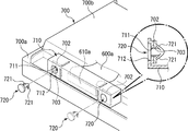
次に、遊技制御基板40と該遊技制御基板40に接続される各種遊技用電子部品との配線接続状態の詳細について、図4に基づいて説明する。尚、図4は、遊技制御基板40と該遊技制御基板40に接続される遊技用電子部品との配線接続状態を示す概略図である。
Next, details of wiring connection states between the
遊技制御基板40には、前述したように、1枚BETスイッチ5、MAXBETスイッチ6、スタートスイッチ7、ストップスイッチ8L、8C、8R、精算スイッチ10、リセットスイッチ23、投入メダルセンサ31、リールセンサ33L、33C、33R、払出センサ35、打止スイッチ36、自動精算スイッチ29、設定キースイッチ37、リセット/設定スイッチ38、演出制御基板90が接続されている。
On the
図4には、遊技制御基板40と接続される各種スイッチ、センサ等の電子部品のうち、賭数を設定する際に操作される1枚BETスイッチ5、MAXBETスイッチ6、ゲームを開始させる際に操作されるスタートスイッチ7、リール2L、2C、2Rの回転を停止する際に操作されるストップスイッチ8L、8C、8R、賭数を設定するために投入されたメダルを検出する投入メダルセンサ31、リール2L、2C、2Rの回転を検出するためのリールセンサ33L、33C、33R、入賞の発生に伴い払い出されるメダルを検出する払出センサ35及び演出制御基板90が示されており、他のスイッチ、センサ等の図示は省略されている。
FIG. 4 shows a
演出制御基板90を除く上記遊技用電子部品5、6、7、8、31、32L、32C、32R、33L、33C、33R、34、35は、ゲームの進行に関わる信号を遊技制御基板40に入出力する電子部品である。ゲームの進行に関わる信号とは、例えば、ゲームを開始可能な状態とするための賭数の設定操作、ゲームを開始させるための操作、リール2L、2C、2Rの表示結果を導出させるための操作等、ゲームの進行操作に応じて遊技制御基板40に出力される信号や、投入メダルの検出、リールの基準位置の検出、払出メダルの検出等、ゲームの進行に応じて遊技用電子部品から出力されて遊技制御基板40に入力される信号と、スタート操作の検出に応じてリール2L、2C、2Rを駆動させるための駆動信号や、入賞の発生に伴いメダルを払い出すホッパーを駆動するための駆動信号等、ゲームの進行に応じて遊技制御基板40から出力されて遊技用電子部品に入力される信号と、を含む。
The gaming
そして、これら遊技用電子部品5、6、7、8、31、32L、32C、32R、33L、33C、33R、34、35は、ゲームの進行に応じて遊技制御基板40に信号を出力する第1の電子部品と、ゲームの進行に応じて遊技制御基板40からの信号が入力される第2の電子部品と、からなる。
These gaming
具体的には、賭数を設定する際に操作される1枚BETスイッチ5、MAXBETスイッチ6及び賭数を設定するために投入されたメダルを検出する投入メダルセンサ31は、該操作またはメダルの検出に基づいて遊技制御基板40にBET信号を出力する第1の電子部品である。メイン制御部41は、該BET信号の受信に基づいて賭数の設定処理を行うため、これら電子部品がないと賭数を設定することができない。すなわち、賭数を設定しないとゲームが開始可能な状態とならないため、1枚BETスイッチ5、MAXBETスイッチ6及び投入メダルセンサ31はゲームの進行に必要な遊技用電子部品である。
Specifically, the
ゲームを開始させるための操作を検出するスタートスイッチ7は、該操作の検出に基づいて遊技制御基板40にスタート信号を出力する第1の電子部品である。メイン制御部41は、該スタート信号の受信に基づいてゲームを開始する処理(リール回転処理等)を行うため、この電子部品がないとゲームを開始することができない。すなわち、スタートスイッチ7はゲームの進行に必要な遊技用電子部品である。
The
リール2L、2C、2Rの表示結果を導出させるための操作を検出するストップスイッチ8L、8C、8Rは、該操作の検出に基づいて遊技制御基板40にストップ信号を出力する第1の電子部品である。メイン制御部41は、該ストップ信号の受信に基づいて該当するリール2L、2C、2Rの回転を停止して表示結果を導出する処理を行うため、この電子部品がないとリール2L、2C、2Rの表示結果を導出することができない。すなわち、ストップスイッチ8L、8C、8Rはゲームの進行に必要な遊技用電子部品である。
Stop switches 8L, 8C, and 8R that detect an operation for deriving the display results of the
リール2L、2C、2Rの回転を検出するリールセンサ33L、33C、33Rは、リールの基準位置の検出信号を遊技制御基板40に出力する第1の電子部品である。メイン制御部41は、該リールの基準位置の検出信号の受信に基づいて該当するリール2L、2C、2Rの図柄の位置を把握して回転を停止する処理等を行うため、この電子部品がないと各リール2L、2C、2Rの表示結果の導出や入賞の判定等を行うことができない。すなわち、リールセンサ33L、33C、33Rはゲームの進行に必要な遊技用電子部品である。
The
入賞の発生に伴い払い出されるメダルを検出する払出センサ35は、該メダルの検出に基づいて遊技制御基板40にメダル払出信号を出力する第1の電子部品である。メイン制御部41は、該払出メダル検出信号の受信に基づいて、発生した入賞に応じた枚数のメダルを払い出す払出処理を行うため、この電子部品がないと発生した入賞に応じた枚数のメダルを払い出すことができない。すなわち、払出センサ35はゲームの進行に必要な遊技用電子部品である。
The
また、リール2L、2C、2Rを回転させるリールモータ32L、32C、32Rは、遊技制御基板40から出力される駆動信号が入力される第2の電子部品である。このリールモータ32L、32C、32Rは、遊技制御基板40から出力される駆動信号の入力に基づいてリール2L、2C、2Rを回転させて図柄の変動表示を開始するものであるが、該信号入力に基づいて実際にリール2L、2C、2Rを回転しなかったとしても、メイン制御部41は、リールの駆動信号を出力した後に上記リールセンサ33L、33C、33Rからの信号が入力されることで、リールが回転したとしてゲームを進行する制御を行うことができる。しかし、このリールセンサ33L、33C、33Rから信号が遊技制御基板40に入力されるタイミングは、リールの駆動信号の出力後でないとエラーとなるため、前述した打ち込み器具によりゲームを進行させる場合において、リールの回転の検出に基づく信号の出力タイミングを計るためにはリールの駆動信号が必要となる。すなわち、リールモータ32L、32C、32Rは、ゲームの進行に必要な遊技用電子部品である。
The
また、メダルの払い出しを行うホッパータンクを駆動するホッパーモータ34は、入賞の発生に応じて遊技制御基板40から出力される駆動信号が入力される第2の電子部品である。このホッパーモータ34は、遊技制御基板40から出力される駆動信号の入力に基づいてホッパータンクを駆動させてメダルを払い出すものであるが、該信号入力に基づいて実際にホッパータンクを駆動しなかったとしても、メイン制御部41は、ホッパータンクの駆動信号を出力した後に上記払出センサ35からの信号が入力されることで、メダルが払い出されているとしてゲームを進行する制御を行うことができる。しかし、この払出センサ35から信号が遊技制御基板40に入力されるタイミングは、ホッパータンクの駆動信号の出力後でないとエラーとなるため、前述した打ち込み器具によりゲームを進行させる場合において、払出メダルの検出に基づく信号の出力タイミングを計るためには該ホッパータンクの駆動信号が必要となる。すなわち、ホッパーモータ34は、ゲームの進行に必要な遊技用電子部品である。
The
また、これら遊技用電子部品5、6、7、8、31、32L、32C、32R、33L、33C、33R、34、35は、基本的には複数の機種に共通して継続使用される電子部品であり、故障等が発生しない限り本体から取り外して交換する機会は少ないので、スロットマシンの本体所定箇所に固設されている。これに対して遊技制御基板40や演出制御基板90等は、機種変更の際には交換が必要となるため、その際には本体から取り外される。つまり、遊技制御基板40を取り外す際には遊技用電子部品5、6、7、8、31、32L、32C、32R、33L、33C、33R、34、35との接続を解除する必要があるため、遊技用電子部品5、6、7、8、31、32L、32C、32R、33L、33C、33R、34、35と遊技制御基板40とは中継基板を経由して接続されているとともに、これら基板同士及び基板と遊技用電子部品とはケーブルを介して接続されている。またケーブルと基板とは、ケーブルの端部に設けられたケーブル側コネクタと基板の配線パターンと電気的に接続された基板側コネクタとの接続により電気的に接続されている。
These gaming
具体的に説明すると、1枚BETスイッチ5、MAXBETスイッチ6、スタートスイッチ7、ストップスイッチ8L、8C、8R、投入メダルセンサ31は、操作部中継基板110を経由して遊技制御基板40と配線接続され、リールモータ32L、32C、32R及びリールセンサ33L、33C、33Rは、リール中継基板120を経由して遊技制御基板40と配線接続され、ホッパーモータ34及び払出センサ35は、電源基板100を経由して遊技制御基板40と配線接続され、演出制御基板90は、演出中継基板80を経由して遊技制御基板40と配線接続されている。
More specifically, the
操作部中継基板110、リール中継基板120、電源基板100、演出制御基板90には、遊技制御基板40と各電子部品5、6、7、8、31、32L、32C、32R、33L、33C、33R、34、35とを接続するための配線パターン(図示略)が設けられており、各電子部品5、6、7、8、31、32L、32C、32R、33L、33C、33R、34、35から遊技制御基板40に対して出力される検出信号または遊技制御基板40から供給(入力)される電力や信号等を中継可能とされている。
The operation
また、このように各種電子部品と遊技制御基板40とを、スロットマシン1の本体所定箇所に取り付けた各中継基板110、120、100、80を経由して配線接続することで、遊技制御基板40からスロットマシン1の本体所定箇所に個々に配設される複数の電子部品との配線の取りまとめが容易になるとともに、コネクタ接続部が常に中継基板または遊技制御基板40に設けられることになり、これにより各電子部品それぞれのコネクタ接続部が固定されるため、配線接続作業時においてコネクタ接続部を探したり、接続する配線の種類を間違うこと等が防止される。
In addition, the
遊技制御基板40と操作部中継基板110とは、ケーブル600aを介して接続され、遊技制御基板40とリール中継基板120とは、ケーブル600bを介して接続され、遊技制御基板40と電源基板100とは、ケーブル600cを介して接続されており、また、演出制御基板90と演出中継基板80とは、ケーブル600dを介して接続されている。
The
操作部中継基板110と1枚BETスイッチ5とはケーブル601aを介して接続され、操作部中継基板110とMAXBETスイッチ6とはケーブル601bを介して接続され、操作部中継基板110とスタートスイッチ7とはケーブル601cを介して接続され、操作部中継基板110とストップスイッチ8Lとはケーブル601dを介して接続され、操作部中継基板110とストップスイッチ8Cとはケーブル601eを介して接続され、操作部中継基板110とストップスイッチ8Rとはケーブル601fを介して接続され、操作部中継基板110と投入メダルセンサ31とはケーブル601gを介して接続されている。
The operation
また、リール中継基板120とリールモータ32Lとはケーブル601hを介して接続され、リール中継基板120とリールモータ32Cとはケーブル601jを介して接続され、リール中継基板120とリールモータ32Rとはケーブル601lを介して接続されている。また、リール中継基板120とリールセンサ33Lとはケーブル601iを介して接続され、リール中継基板120とリールセンサ33Cとはケーブル601kを介して接続され、リール中継基板120とリールセンサ33Lとはケーブル601mを介して接続されている。また、電源基板100とホッパーモータ34とはケーブル601nを介して接続され、電源基板100と払出センサ35とはケーブル601oを介して接続され、演出中継基板80と演出制御基板90とはケーブル601pを介して接続されている。
The
これら各ケーブル600a〜600c、601a〜601oは、各基板に対してコネクタ接続されており、基板との配線接続を解除可能となっている。具体的には、ケーブル600aの両端には、ケーブル側コネクタ610a、611aが設けられており、一方のケーブル側コネクタ610aは、遊技制御基板40に固設された基板側コネクタ620aに接続可能なコネクタであり、他方のケーブル側コネクタ611aは、操作部中継基板110に固設された基板側コネクタ621aに接続可能なコネクタである。ケーブル600bの両端には、ケーブル側コネクタ610b、611bが設けられており、一方のケーブル側コネクタ610bは、遊技制御基板40に固設された基板側コネクタ620bに接続可能なコネクタであり、他方のケーブル側コネクタ611bは、リール中継基板120に固設された基板側コネクタ621bに接続可能なコネクタである。ケーブル600cの両端には、ケーブル側コネクタ610c、611cが設けられており、一方のケーブル側コネクタ610cは、遊技制御基板40に固設された基板側コネクタ620cに接続可能なコネクタであり、他方のケーブル側コネクタ611cは、電源基板100に固設された基板側コネクタ621cに接続可能なコネクタである。ケーブル600dの両端には、ケーブル側コネクタ610d、611dが設けられており、一方のケーブル側コネクタ610dは、遊技制御基板40に固設された基板側コネクタ620dに接続可能なコネクタであり、他方のケーブル側コネクタ611dは、演出中継基板80に固設された基板側コネクタ621dに接続可能なコネクタである。
Each of these
また、一端が1枚BETスイッチ5に接続されたケーブル601aの他端には、操作部中継基板110に固設された基板側コネクタ622aに接続可能なケーブル側コネクタ612aが設けられている。一端がMAXBETスイッチ6に接続されたケーブル601bの他端には、操作部中継基板110に固設された基板側コネクタ622bに接続可能なケーブル側コネクタ612bが設けられている。一端がスタートスイッチ7に接続されたケーブル601cの他端には、操作部中継基板110に固設された基板側コネクタ622cに接続可能なケーブル側コネクタ612cが設けられている。一端がストップスイッチ8Lに接続されたケーブル601dの他端には、操作部中継基板110に固設された基板側コネクタ622dに接続可能なケーブル側コネクタ612dが設けられている。一端がストップスイッチ8Cに接続されたケーブル601eの他端には、操作部中継基板110に固設された基板側コネクタ622eに接続可能なケーブル側コネクタ612eが設けられている。一端がストップスイッチ8Rに接続されたケーブル601fの他端には、操作部中継基板110に固設された基板側コネクタ622fに接続可能なケーブル側コネクタ612fが設けられている。一端が投入メダルセンサ31に接続されたケーブル601gの他端には、操作部中継基板110に固設された基板側コネクタ622gに接続可能なケーブル側コネクタ612gが設けられている。
Further, a cable-
また、一端がリールモータ32Lに接続されたケーブル601hの他端及び一端がリールセンサ33Lに接続されたケーブル601iの他端には、リール中継基板120に固設された基板側コネクタ622hに接続可能なケーブル側コネクタ612hが設けられている。一端がリールモータ32Cに接続されたケーブル601jの他端及び一端がリールセンサ33Cに接続されたケーブル601kの他端には、リール中継基板120に固設された基板側コネクタ622iに接続可能なケーブル側コネクタ612iが設けられている。一端がリールモータ32Rに接続されたケーブル601lの他端及び一端がリールセンサ33Rに接続されたケーブル601mの他端には、リール中継基板120に固設された基板側コネクタ622jに接続可能なケーブル側コネクタ612jが設けられている。
Further, the other end of the
また、一端がホッパーモータ34に接続されたケーブル601nの他端及び一端が払出センサ35に接続されたケーブル601oの他端には、電源基板100に固設された基板側コネクタ622kに接続可能なケーブル側コネクタ612kが設けられている。
Further, the other end of the
また、ケーブル601pの両端には、ケーブル側コネクタ612p、613pが設けられており、一方のケーブル側コネクタ612pは、遊技制御基板40に固設された基板側コネクタ622pに接続可能なコネクタであり、他方のケーブル側コネクタ613pは、演出制御基板90に固設された基板側コネクタ623pに接続可能なコネクタである。
In addition, cable-
尚、本実施例では、各電子部品5、6、7、8、31、32L、32C、32R、33L、33C、33R、34、35からはコネクタを介すことなく配線が延出されているが、コネクタを介して配線と接続されていても良い。
In this embodiment, wiring is extended from each
上述のように、各基板と各ケーブルとは、基板側に設けられる基板側コネクタ620a〜620d、621a〜621d、622a〜622k、622p、623pと、ケーブル側に設けられるケーブル側コネクタ610a〜610d、611a〜611d、612a〜612k、612p、613pとからなる一対のコネクタ(雄コネクタと雌コネクタ)を介して配線接続されており、基板側コネクタからケーブル側コネクタを抜脱することにより配線接続を解除することができるようになっている。特に、遊技制御基板40、操作部中継基板110、リール中継基板120、電源基板100、演出制御基板90は、スロットマシン1の筐体または前面扉の所定箇所に取り付けられていることで、基板側コネクタからケーブル側コネクタを抜脱しやすいので、遊技制御基板40や演出制御基板90の交換が容易に行うことができる。
As described above, each board and each cable includes board-
まず第1の電子部品に関して具体的に説明すると、1枚BETスイッチ5、MAXBETスイッチ6または投入メダルセンサ31と遊技制御基板40との間に設けられるケーブルのコネクタのうちいずれかのコネクタに打ち込み器具のコネクタが接続され、該打ち込み器具から遊技制御基板40にBET信号が不正に出力されると、賭数の設定操作が行われていないのにメイン制御部41にを行うことなく賭数が設定される虞がある。スタートスイッチ7と遊技制御基板40との間に設けられるケーブルのコネクタのうちいずれかのコネクタに打ち込み器具のコネクタが接続され、該打ち込み器具から遊技制御基板40にスタート信号が不正に出力されると、ゲームの開始操作を行うことなくゲームが開始される虞がある。ストップスイッチ8L、8C、8Rと遊技制御基板40との間に設けられるケーブルのコネクタのうちいずれかのコネクタに打ち込み器具のコネクタが接続され、該打ち込み器具から遊技制御基板40にストップ信号が不正に出力されると、停止操作を行うことなくリールの回転が停止される虞がある。リールセンサ33L、33C、33Rと遊技制御基板40との間に設けられるケーブルのコネクタのうちいずれかのコネクタに打ち込み器具のコネクタが接続され、該打ち込み器具から遊技制御基板40にリール回転信号が不正に出力されると、リールを回転させることなく各リール2L、2C、2Rの表示結果の導出や入賞の判定等が行われる虞がある。払出センサ35と遊技制御基板40との間に設けられるケーブルのコネクタのうちいずれかのコネクタに打ち込み器具のコネクタが接続され、該打ち込み器具から遊技制御基板40にメダル払出信号が不正に出力されると、メダルを払い出すことなくメダルの計数が行われる虞がある。
First, the first electronic component will be described in detail. One of the
第2の電子部品に関して具体的に説明すると、リールモータ32L、32C、32Rと遊技制御基板40との間に設けられるケーブルのコネクタのうちいずれかのコネクタでの接続が解除されて遊技制御基板40から出力される駆動信号を打ち込み器具等で取得できることになると、リールの駆動信号が遊技制御基板40から出力されたタイミングを打ち込み器具側で特定できるので、本来リールセンサ33L、33C、33Rから遊技制御基板40に入力されるリール回転検出信号を、打ち込み器具からリール回転後の適正なタイミングで出力されてしまう虞がある。また、ホッパーモータ34と遊技制御基板40との間に設けられるケーブルのコネクタのうちいずれかのコネクタでの接続が解除されて遊技制御基板40から出力される駆動信号を打ち込み器具等で取得できることになると、ホッパータンクの駆動信号が遊技制御基板40から出力されたタイミングを打ち込み器具側で特定できるので、本来払出センサ35から遊技制御基板40に入力される払出メダル検出信号を、打ち込み器具からホッパータンクの駆動後の適正なタイミングで出力されてしまう虞がある。
The second electronic component will be described in detail. The
このように、ゲームの進行に応じて第1の電子部品5、6、7、8、31、33L、33C、33R、35から出力され、本来であれば遊技制御基板40に入力される信号が打ち込み器具から出力された場合、メイン制御部41は該信号の受信に基づいてゲームを進行する制御を行うことができるとともに、ゲームの進行に応じて遊技制御基板40から出力され、本来であれば第2の電子部品32L、32C、32R、34に入力される信号が打ち込み器具に入力された場合、打ち込み器具側では、メイン制御部41がリールモータやホッパーモータの駆動後に出力する信号の出力タイミング等を特定可能となり、これに基づいて新たな信号がメイン制御基板40に入力された場合には、メイン制御部41は該信号の受信に基づいてゲームを進行する制御を行うことができるので、ゲームを自動的に進行させるといった不正行為が実施される虞がある。よって、本実施例では、打ち込み器具の接続による不正行為を防止する種々の対策が施されている。尚、これらの対策については後に詳述する。
As described above, the signals that are output from the first
次に、遊技制御基板40における断線監視IC50の周辺の構成を説明する。
Next, a configuration around the
遊技制御基板40には、電源基板100の電圧生成回路により生成された+5Vの直流電圧が供給される。電源基板100から供給された+5Vの直流電圧は、断線監視IC50の駆動電源として電源端子(VDD)に供給されるとともに、図5に示すように、遊技制御基板40上で分岐して遊技制御基板40と操作部中継基板110を配線接続するケーブル600a、操作部中継基板110、操作部中継基板110と投入メダルセンサ31を配線接続するケーブル601gを経由し、更に、投入メダルセンサ31で折り返して、ケーブル601g、操作部中継基板110、ケーブル600aを経由して遊技制御基板40に戻り、更に、遊技制御基板40と演出中継基板80を配線接続するケーブル600d、演出中継基板80、演出中継基板80と演出制御基板90を配線接続するケーブル601p、を経由し、更に、演出制御基板90で折り返して、ケーブル601p、演出中継基板80、ケーブル600dを経由して再度遊技制御基板40に戻り、断線監視IC50の入力端子(IN)に接続信号として入力されるようになっている。
The
このため、本実施例では、遊技制御基板40の基板側コネクタ620aとケーブル600aのケーブル側コネクタ610aとの接続、ケーブル600aのケーブル側コネクタ611aと操作部中継基板110の基板側コネクタ621aとの接続、操作部中継基板110の基板側コネクタ622gとケーブル601gのケーブル側コネクタ612gとの接続、遊技制御基板40の基板側コネクタ620dとケーブル600dのケーブル側コネクタ610dとの接続、ケーブル600dのケーブル側コネクタ611dと演出中継基板80の基板側コネクタ621dとの接続、演出中継基板80の基板側コネクタ622pとケーブル601pのケーブル側コネクタ612pとの接続、ケーブル601pのケーブル側コネクタ613pと演出制御基板90の基板側コネクタ623pとの接続、のいずれかの接続を解除することで、断線監視IC50の入力端子(IN)へ入力されている接続信号が遮断され、これにより断線監視IC50が遊技制御基板40と投入メダルセンサ31間及び遊技制御基板40と演出制御基板90間の断線を検出するようになっている。すなわち遊技制御基板40と投入メダルセンサ31の間のコネクタ同士の接続及び遊技制御基板40と演出制御基板90の間のコネクタ同士の接続が1カ所でも解除されると、断線監視IC50により断線が検出されるようになっている。
For this reason, in this embodiment, the board-
また、図5に示すように、電源基板100から供給された+5Vの直流電圧は、遊技制御基板40上で分岐して電源基板100側でグラウンドレベルに接続されるとともに、その間には大容量のコンデンサC1が設けられている。D1は逆流防止用のダイオードである。これにより+5Vの直流電圧をコンデンサC1に蓄積可能とされ、スロットマシン1に対する電力供給が遮断されたときに、コンデンサC1に蓄積された電圧を、断線監視IC50を駆動するためのバックアップ電源として供給できるようになっており、通電時であるか停電時であるかに関わらず断線監視IC50が遊技制御基板40と投入メダルセンサ31間及び遊技制御基板40と演出制御基板90間の断線を検出できるようになっている。
Further, as shown in FIG. 5, the + 5V DC voltage supplied from the
本実施例のスロットマシン1は、設定値に応じてメダルの払出率が変わるものであり、後述する内部抽選の当選確率は、設定値に応じて定まるものとなる。以下、設定値の変更操作について説明する。
In the
設定値を変更するためには、設定キースイッチ37をON状態としてからスロットマシン1の電源をONする必要がある。設定キースイッチ37をON状態として電源をONすると、設定値表示器24に設定値の初期値として1が表示され、リセット/設定スイッチ38の操作による設定値の変更操作が可能な設定変更モードに移行する。設定変更モードにおいて、リセット/設定スイッチ38が操作されると、設定値表示器24に表示された設定値が1ずつ更新されていく(設定6から更に操作されたときは、設定1に戻る)。そして、スタートスイッチ7が操作されると設定値が確定し、確定した設定値がメイン制御部41のRAM41cに格納される。そして、設定キースイッチ37がOFFされると、遊技の進行が可能な状態に移行する。
In order to change the setting value, it is necessary to turn on the power of the
本実施例のスロットマシン1において、CPU41aは、その起動時において断線監視IC50に断線フラグの確認要求を行い、これに伴う断線監視IC50からの返信に基づき断線フラグの記憶状態を取得し、断線フラグが記憶されている場合には、断線異常と判定し、断線異常エラーコードをレジスタにセットして断線異常エラー状態に制御し、遊技の進行を不能化させるようになっている。尚、断線異常エラー状態は、通常のエラー状態と異なり、リセットスイッチ23やリセット/設定スイッチ38を操作しても解除されることがないうえに、RAM41cの領域のうちCPU41aが使用中の領域を除く全ての領域が初期化され、元の状態には復帰不可能となり、前述した設定変更モードにおいて新たな設定値が設定されるまで解除されることがない。
In the
また、CPU41aは、定期的に実行されるタイマ割込処理においても断線監視IC50の断線フラグの記憶状態を取得し、断線フラグが記憶されている場合には、起動時と同様に断線異常と判定し、断線異常エラーコードをレジスタにセットして断線異常エラー状態に制御し、この場合にも元の状態には復帰不可能となり、前述した設定変更モードにおいて新たな設定値が設定されるまで解除されることがない。
Further, the
本実施例のスロットマシン1においては、メイン制御部41のCPU41aが電圧低下信号を検出した際に、電断割込処理(メイン)を実行する。電断割込処理(メイン)では、レジスタを後述するRAM41cのスタックに退避し、メイン制御部41のRAM41cにいずれかのビットが1となる破壊診断用データ(本実施例では、5AH)、すなわち0以外の特定のデータを格納するとともに、RAM41cの全ての領域に格納されたデータに基づくRAMパリティが0となるようにRAMパリティ調整用データを計算し、RAM41cに格納する処理を行うようになっている。尚、RAMパリティとはRAM41cの該当する領域(本実施例では、全ての領域)の各ビットに格納されている値の排他的論理和として算出される値である。このため、RAM41cの全ての領域に格納されたデータに基づくRAMパリティが0であれば、RAMパリティ調整用データは0となり、RAM41cの全ての領域に格納されたデータに基づくRAMパリティが1であれば、RAMパリティ調整用データは1となる。
In the
そして、CPU41aは、その起動時においてRAM41cの全ての領域に格納されたデータに基づいてRAMパリティを計算するとともに、破壊診断用データの値を確認し、RAMパリティが0であり、かつ破壊診断用データの値も正しいことを条件に、RAM41cに記憶されているデータに基づいてCPU41aの処理状態を電断前の状態に復帰させるが、RAMパリティが0でない場合(1の場合)や破壊診断用データの値が正しくない場合には、RAM異常と判定し、RAM異常エラーコードをレジスタにセットしてRAM異常エラー状態に制御し、遊技の進行を不能化させるようになっている。尚、RAM異常エラー状態は、他のエラー状態と異なり、リセットスイッチ23やリセット/設定スイッチ38を操作しても解除されないようになっており、前述した設定変更モードにおいて新たな設定値が設定されるまで解除されることがない。
The
また、CPU41aは、後述する内部抽選処理において設定された賭数が遊技状態に応じた賭数であるか否かを判定するとともに、内部抽選に用いる設定値が適正な値であるか否かを判定する。
Further, the
そして、設定された賭数が遊技状態に応じた賭数ではない場合、または内部抽選に用いる設定値が適正な値でない場合にも、RAM異常と判定し、RAM異常エラーコードをセットしてRAM異常エラー状態に制御し、遊技の進行を不能化させるようになっている。尚、前述のようにRAM異常エラー状態は、他のエラー状態と異なり、リセットスイッチ23やリセット/設定スイッチ38を操作しても解除されないようになっており、前述した設定変更モードにおいて新たな設定値が設定されるまで解除されることがない。
Even when the set bet number is not the bet number according to the gaming state, or when the set value used for the internal lottery is not an appropriate value, it is determined that the RAM is abnormal and the RAM abnormal error code is set and the RAM is set. The game is controlled to an abnormal error state and the progress of the game is disabled. As described above, unlike the other error states, the RAM abnormal error state is not canceled even if the
また、CPU41aは、起動時にRAM41cに記憶されているデータに基づいて処理状態を電断前の状態に復帰させる場合に、いずれかの特別役の当選フラグが設定されているか否か、すなわち電断前にいずれかの特別役が当選していたか否かを判定し、いずれかの特別役の当選フラグが設定されている場合には、特別役の当選を示す電源投入コマンドを送信し、サブ制御部91に対して特別役が当選している旨の報知を指示する。一方、いずれの特別役の当選フラグも設定されていない場合には、特別役の非当選を示す電源投入コマンドを送信する。サブ制御部91のCPU91aは、起動時にメイン制御部41から電源投入コマンドを受信したときに、特別役の当選を示す電源投入コマンドであれば液晶表示器51などによって特別役の当選を示す告知演出を実行し、その後その特別役が入賞するまで継続するのに対して、特別役の非当選を示す電源投入コマンドであれば、バックアップされている演出状態に復帰する。
Further, when the
また、サブ制御部91のCPU91aは、電源投入コマンドか、後述するようにメイン制御部41の制御状態が初期化された旨を示す初期化コマンドを受信するまでは、バックアップが正常であってもその演出状態に復帰することもなく、他のコマンドを受信してもそれに応じて演出の制御は行わないようになっている。このため、起動時にメイン制御部41とサブ制御部91のコマンド送信ラインを非接続とし、その後メイン制御部41とサブ制御部91とを接続しても、CPU91aは、電源投入コマンドや初期化コマンドを受信していないため、演出の制御が行われることはなく、起動時にメイン制御部41とサブ制御部91のコマンド送信ラインを非接続としても、サブ制御部91側で電源投入コマンドの受信を回避し、特別役の当選を示す告知演出の実行を回避することは不可能である。
Even if the backup is normal until the
すなわち、メイン制御部41の起動時に電断前の状態に復帰し、かつ電断前から特別役が当選している場合には、特別役の当選を示す電源投入コマンドを送信し、特別役の当選を示す電源投入コマンドをサブ制御部91が受信すると、特別役の当選を示す告知演出を実行するとともに、サブ制御部91側で電源投入コマンドの受信を回避し、特別役の当選を示す告知演出の実行を回避することは不可能であるため、このようにメイン制御部41の起動時に電断前の状態に復帰し、かつ電断前から特別役が当選している場合には、必ず特別役の当選が報知されることとなる。
That is, when the
本実施例のスロットマシン1は、前述のように遊技状態に応じて設定可能な賭数の規定数が定められており、遊技状態に応じて定められた規定数の賭数が設定されたことを条件にゲームを開始させることが可能となる。本実施例では、後に説明するが、遊技状態として、レギュラーボーナス、初期遊技状態、RT(1)及びRT(2)があり、このうちレギュラーボーナスに対応する賭数の規定数として1が定められており、初期遊技状態、RT(1)及びRT(2)に対応する賭数の規定数として3が定められている。このため、遊技状態がレギュラーボーナスにあるときには、賭数として1が設定されるとゲームを開始させることが可能となり、遊技状態が初期遊技状態、RT(1)またはRT(2)にあるときには、賭数として3が設定されるとゲームを開始させることが可能となる。尚、本実施例では、遊技状態に応じた規定数の賭数が設定された時点で、全ての入賞ラインL1〜L4が有効化されるようになっており、遊技状態に応じた規定数が1であれば、賭数として1が設定された時点で全ての入賞ラインL1〜L4が有効化され、遊技状態に応じた規定数が3であれば、賭数として3が設定された時点で全ての入賞ラインL1〜L4が有効化されることとなる。
In the
また、全てのリール2L、2C、2Rが停止した際に、有効化された入賞ライン(本実施例の場合、常に全ての入賞ラインが有効化されるため、以下では、有効化された入賞ラインを単に入賞ラインと呼ぶ)上に役と呼ばれる図柄の組み合わせが揃うと入賞となる。入賞となる役の種類は、遊技状態に応じて定められているが、大きく分けて、メダルの払い出しを伴う小役と、賭数の設定を必要とせずに次のゲームを開始可能となる再遊技役と、遊技状態の移行を伴う特別役と、がある。以下では、小役と再遊技役をまとめて一般役とも呼ぶ。遊技状態に応じて定められた各役の入賞が発生するためには、後述する内部抽選に当選して、当該役の当選フラグがRAM41cに設定されている必要がある。
Also, when all
尚、これら各役の当選フラグのうち、小役及び再遊技役の当選フラグは、当該フラグが設定されたゲームにおいてのみ有効とされ、次のゲームでは無効となるが、特別役の当選フラグは、当該フラグにより許容された役の組み合わせが揃うまで有効とされ、許容された役の組み合わせが揃ったゲームにおいて無効となる。すなわち特別役の当選フラグが一度当選すると、例え、当該フラグにより許容された役の組み合わせを揃えることができなかった場合にも、その当選フラグは無効とされずに、次のゲームへ持ち越されることとなる。 Of the winning flags for each of these combinations, the winning flag for the small role and the re-playing role is valid only in the game in which the flag is set, and is invalid in the next game. It is valid until the combination of combinations permitted by the flag is complete, and is invalid in a game having the combination of combinations permitted. In other words, once the winning flag for a special role is won, even if the combination of characters allowed by the flag cannot be aligned, the winning flag is not invalidated and carried over to the next game. It becomes.
図6は、当選役テーブルを示す図である。当選役テーブルは、メイン制御部41のROM41bに予め格納されており、内部抽選において抽選対象となる役及び役の組み合わせに対応して、抽選が行われる順番に割り当てられた役番号(0〜19)が登録されている。
FIG. 6 is a diagram showing a winning combination table. The winning combination table is stored in advance in the
このスロットマシン1における役としては、特別役としてビッグボーナス(1)、ビッグボーナス(2)、レギュラーボーナスが、小役としてスイカ、チェリー、1枚(1)、1枚(2)、1枚(3)、ベルが、再遊技役としてリプレイ(1)、リプレイ(2)、リプレイ(3)、リプレイ(4)が定められている。また、スロットマシン1における役の組み合わせとしては、ビッグボーナス(1)+チェリー、ビッグボーナス(2)+チェリー、ビッグボーナス(1)+1枚(1)、ビッグボーナス(2)+1枚(1)、ビッグボーナス(1)+1枚(2)、ビッグボーナス(2)+1枚(2)、ビッグボーナス(1)+1枚(3)、ビッグボーナス(2)+1枚(3)、リプレイ(1)+リプレイ(2)、リプレイ(1)+リプレイ(3)、リプレイ(1)+リプレイ(4)が定められている。ただしリプレイ(2)〜(4)は単独で抽選の対象となることはなく、必ずリプレイ(1)との組み合わせが抽選の対象となるため、役及び役の組み合わせの合計は20となっている。
In the
本実施例では、図6に示すように、遊技状態が、初期遊技状態(初期遊技状態とは後述するボーナス中、RT(1)及びRT(2)以外の遊技状態であり、いずれかのボーナスの終了後、設定変更後、RT(1)の終了後、またはRT(2)の終了後の遊技状態が該当する)、RT(1)またはRT(2)であるか、レギュラーボーナスであるか、によって抽選の対象となる役及び役の組み合わせが異なる。更に遊技状態が初期遊技状態、RT(1)またはRT(2)である場合には、いずれかの特別役の持ち越し中か否か(特別役の当選フラグにいずれかの特別役が当選した旨が既に設定されているか否か)によっても抽選の対象となる役及び役の組み合わせが異なる。また、初期遊技状態であるか、RT(1)であるか、RT(2)であるか、によって抽選の対象となる役及び役の組み合わせは同じであるが当選確率が異なる。本実施例では、遊技状態に応じた状態番号が割り当てられており、内部抽選を行う際に、現在の遊技状態に応じた状態番号を設定し、この状態番号に応じて抽選対象となる役を特定することが可能となる。具体的には、初期遊技状態においていずれの特別役も持ち越されていない場合には、状態番号として「0」が設定され、RT(1)においていずれの特別役も持ち越されていない場合には、状態番号として「1」が設定され、RT(2)においていずれの特別役も持ち越されていない場合には、状態番号として「2」が設定され、初期遊技状態においていずれかの特別役が持ち越されている場合には、状態番号として「3」が設定され、RT(1)においていずれかの特別役が持ち越されている場合には、状態番号として「4」が設定され、RT(2)においていずれかの特別役が持ち越されている場合には、状態番号として「5」が設定され、レギュラーボーナスである場合には、状態番号として「6」が設定されるようになっている。 In this embodiment, as shown in FIG. 6, the gaming state is an initial gaming state (the initial gaming state is a gaming state other than RT (1) and RT (2) during a bonus described later, and any bonus The game state after completion of RT, after changing settings, after completion of RT (1), or after completion of RT (2)), whether it is RT (1) or RT (2), or is it a regular bonus? , And the combination of combinations and combinations that are subject to lottery. Furthermore, when the gaming state is the initial gaming state, RT (1) or RT (2), whether or not any special role is being carried over (the fact that any special role has been elected in the special feature winning flag) Depending on whether or not is already set, the combination and combination of combinations that are subject to the lottery vary. Also, depending on whether the game is in the initial gaming state, RT (1) or RT (2), the winning combination and combination of winning combinations are the same, but the winning probabilities are different. In this embodiment, a state number corresponding to the gaming state is assigned, and when performing an internal lottery, a state number corresponding to the current gaming state is set, and a role to be a lottery object is determined according to this state number. It becomes possible to specify. Specifically, when no special combination is carried over in the initial gaming state, “0” is set as the state number, and when no special combination is carried over at RT (1), If “1” is set as the state number and no special combination is carried over in RT (2), “2” is set as the state number, and any special combination is carried over in the initial gaming state. If the special number is carried over at RT (1), "4" is set as the state number, and at RT (2) When any special combination is carried over, “5” is set as the state number, and when it is a regular bonus, “6” is set as the state number.
図6に示すように、遊技状態が初期遊技状態、RT(1)またはRT(2)であり、いずれの特別役も持ち越されていない状態、すなわち状態番号として「0」、「1」、「2」のいずれかが設定されている場合には、ビッグボーナス(1)、ビッグボーナス(2)、レギュラーボーナス、ビッグボーナス(1)+チェリー、ビッグボーナス(2)+チェリー、ビッグボーナス(1)+1枚(1)、ビッグボーナス(2)+1枚(1)、ビッグボーナス(1)+1枚(2)、ビッグボーナス(2)+1枚(2)、ビッグボーナス(1)+1枚(3)、ビッグボーナス(2)+1枚(3)、リプレイ(1)、リプレイ(1)+リプレイ(2)、リプレイ(1)+リプレイ(3)、リプレイ(1)+リプレイ(4)、スイカ、チェリー、1枚(1)、1枚(2)、1枚(3)、ベル、すなわち全ての役及び役の組み合わせが内部抽選の対象となる。また、遊技状態が初期遊技状態、RT(1)またはRT(2)であり、いずれかの特別役が持ち越されている状態、すなわち状態番号として「3」、「4」、[5]のいずれかが設定されている場合には、リプレイ(1)、リプレイ(1)+リプレイ(2)、リプレイ(1)+リプレイ(3)、リプレイ(1)+リプレイ(4)、スイカ、チェリー、1枚(1)、1枚(2)、1枚(3)、ベル、すなわち役番号11以降の役及び役の組み合わせが内部抽選の対象となる。また、遊技状態がレギュラーボーナス、すなわち状態番号として「6」が設定されている場合には、スイカ、チェリー、1枚(1)、1枚(2)、1枚(3)、ベル、すなわち役番号14以降の役及び役の組み合わせが内部抽選の対象となる。
As shown in FIG. 6, the gaming state is the initial gaming state, RT (1) or RT (2), and no special role is carried over, that is, state numbers “0”, “1”, “ 2 ”is set, big bonus (1), big bonus (2), regular bonus, big bonus (1) + cherry, big bonus (2) + cherry, big bonus (1) +1 (1), Big Bonus (2) +1 (1), Big Bonus (1) +1 (2), Big Bonus (2) +1 (2), Big Bonus (1) +1 (3), Big Bonus (2) + 1 (3), Replay (1), Replay (1) + Replay (2), Replay (1) + Replay (3), Replay (1) + Replay (4), Watermelon, Cherry, 1 (1 , One (2), one (3), the bell, that is, the combination of all roles and role as a target of the internal lottery. Also, the gaming state is the initial gaming state, RT (1) or RT (2), and any special role is carried over, that is, any of state numbers “3”, “4”, and [5] Is set, replay (1), replay (1) + replay (2), replay (1) + replay (3), replay (1) + replay (4), watermelon, cherry, 1 The sheet (1), the sheet (2), the sheet (3), the bell, that is, the combination of the combination and combination after the
スイカは、いずれの遊技状態においても入賞ラインのいずれかに「スイカ−スイカ−スイカ」の組み合わせが揃ったときに入賞となり、初期遊技状態、RT(1)及びRT(2)においては5枚のメダルが払い出され、レギュラーボーナスにおいては15枚のメダルが払い出される。チェリーは、いずれの遊技状態においても左リールについて入賞ラインのいずれかに「チェリー」の図柄が導出されたときに入賞となり、初期遊技状態、RT(1)及びRT(2)においては2枚のメダルが払い出され、レギュラーボーナスにおいては15枚のメダルが払い出される。尚、「チェリー」の図柄が左リールの上段または下段に停止した場合には、入賞ラインL1、L3または入賞ラインL2、L4の2本の入賞ラインにチェリーの組み合わせが揃うこととなり、2本の入賞ライン上でチェリーに入賞したこととなるので、初期遊技状態、RT(1)及びRT(2)においては4枚のメダルが払い出されることとなるが、レギュラーボーナスでは、2本の入賞ライン上でチェリーに入賞しても、1ゲームにおいて払い出されるメダル枚数の上限が15枚に設定されているため、15枚のみメダルが払い出されることとなる。1枚(1)は、いずれの遊技状態においても入賞ラインのいずれかに「赤7−ベル−any(anyはいずれの図柄でも可)」の組み合わせが揃ったときに入賞となり、初期遊技状態、RT(1)及びRT(2)においては1枚のメダルが払い出され、レギュラーボーナスにおいては15枚のメダルが払い出される。1枚(2)は、いずれの遊技状態においても入賞ラインのいずれかに「白7−ベル−any」の組み合わせが揃ったときに入賞となり、初期遊技状態、RT(1)及びRT(2)においては1枚のメダルが払い出され、レギュラーボーナスにおいては15枚のメダルが払い出される。1枚(3)は、いずれの遊技状態においても入賞ラインのいずれかに「黒BAR−ベル−any」の組み合わせが揃ったときに入賞となり、初期遊技状態、RT(1)及びRT(2)においては1枚のメダルが払い出され、レギュラーボーナスにおいては15枚のメダルが払い出される。ベルは、いずれの遊技状態においても入賞ラインのいずれかに「ベル−ベル−ベル」の組み合わせが揃ったときに入賞となり、初期遊技状態、RT(1)及びRT(2)においては10枚のメダルが払い出され、レギュラーボーナスにおいては15枚のメダルが払い出される。 A watermelon is awarded when a combination of “watermelon-watermelon-watermelon” is aligned on any of the winning lines in any gaming state, and five in the initial gaming state, RT (1) and RT (2). Medals are paid out, and 15 medals are paid out in the regular bonus. Cherry is awarded when the “Cherry” symbol is derived on any of the winning lines for the left reel in any gaming state, and two in the initial gaming state, RT (1) and RT (2). Medals are paid out, and 15 medals are paid out in the regular bonus. When the “cherry” symbol stops at the upper or lower stage of the left reel, the combination of cherries is aligned on the two winning lines L1 and L3 or the winning lines L2 and L4. Since winning a cherry on the winning line, four medals will be paid out in the initial gaming state, RT (1) and RT (2), but in the regular bonus, two medals are on the winning line. Even if the cherry is won, the upper limit of the number of medals to be paid out in one game is set to 15, so that only 15 medals are paid out. One (1) is awarded when the combination of “Red 7-Bell-any (any can be any symbol)” is placed on any of the winning lines in any gaming state. In RT (1) and RT (2), one medal is paid out, and in the regular bonus, 15 medals are paid out. One (2) wins when the combination of “white 7-bell-any” is aligned on any of the winning lines in any gaming state, and the initial gaming state, RT (1) and RT (2) In, one medal is paid out, and in the regular bonus, 15 medals are paid out. One (3) wins when the combination of “black BAR-bell-any” is aligned on any of the winning lines in any gaming state, and the initial gaming state, RT (1) and RT (2) In, one medal is paid out, and in the regular bonus, 15 medals are paid out. A bell is awarded when a combination of “bell-bell-bell” is aligned on any of the winning lines in any gaming state, and 10 in the initial gaming state, RT (1) and RT (2). Medals are paid out, and 15 medals are paid out in the regular bonus.
リプレイ(1)は、初期遊技状態、RT(1)及びRT(2)において入賞ラインのいずれかに「リプレイ−リプレイ−リプレイ」の組み合わせが揃ったときに入賞となる。リプレイ(2)は、初期遊技状態、RT(1)及びRT(2)において入賞ラインのいずれかに「赤7−リプレイ−リプレイ」の組み合わせが揃ったときに入賞となる。リプレイ(3)は、初期遊技状態、RT(1)及びRT(2)において入賞ラインのいずれかに「白7−リプレイ−リプレイ」の組み合わせが揃ったときに入賞となる。リプレイ(4)は、初期遊技状態、RT(1)及びRT(2)において入賞ラインのいずれかに「黒BAR−リプレイ−リプレイ」の組み合わせが揃ったときに入賞となる。リプレイ(1)〜(4)が入賞したときには、メダルの払い出しはないが次のゲームを改めて賭数を設定することなく開始できるので、次のゲームで設定不要となった賭数(レギュラーボーナスではリプレイ入賞しないので必ず3)に対応した3枚のメダルが払い出されるのと実質的には同じこととなる。 Replay (1) is awarded when the combination of “replay-replay-replay” is aligned on any of the winning lines in the initial gaming state, RT (1) and RT (2). Replay (2) is awarded when the combination of “Red 7-Replay-Replay” is aligned on any of the winning lines in the initial gaming state, RT (1) and RT (2). Replay (3) is awarded when the combination of “white 7-replay-replay” is aligned on any of the winning lines in the initial gaming state, RT (1) and RT (2). Replay (4) is awarded when the combination of “black BAR-replay-replay” is aligned on any of the winning lines in the initial gaming state, RT (1) and RT (2). When replays (1) to (4) win, there is no payout of medals, but the next game can be started without setting the number of bets again. Since there is no replay winning, this is essentially the same as the case where three medals corresponding to 3) are paid out.
レギュラーボーナスは、初期遊技状態、RT(1)及びRT(2)において入賞ラインのいずれかに「黒BAR−黒BAR−赤7」の組み合わせが揃ったときに入賞となる。レギュラーボーナスが入賞すると、遊技状態が初期遊技状態、RT(1)またはRT(2)からレギュラーボーナスに移行する。レギュラーボーナスは、12ゲームを消化したとき、または8ゲーム入賞(役の種類は、いずれでも可)したとき、のいずれか早いほうで終了する。遊技状態がレギュラーボーナスにある間は、レギュラーボーナス中フラグがRAM41cに設定される。
The regular bonus is awarded when the combination of “black BAR-black BAR-red 7” is aligned on any of the winning lines in the initial gaming state, RT (1) and RT (2). When the regular bonus is won, the gaming state shifts from the initial gaming state, RT (1) or RT (2) to the regular bonus. The regular bonus ends when 12 games are consumed, or when 8 games are won (any kind of combination is possible), whichever comes first. While the game state is in the regular bonus, the regular bonus medium flag is set in the
ビッグボーナスは、初期遊技状態、RT(1)及びRT(2)において入賞ラインのいずれかに「赤7−赤7−赤7」の組み合わせ、または「白7−白7−赤7」の組み合わせが揃ったときに入賞となる。また、これらの組み合わせのうち「赤7−赤7−赤7」の組み合わせが揃ったときに入賞となるビッグボーナスはビッグボーナス(1)であり、「白7−白7−赤7」の組み合わせが揃ったときに入賞となるビッグボーナスはビッグボーナス(2)である。ビッグボーナス(1)が入賞すると、遊技状態がビッグボーナス(1)に移行する。ビッグボーナス(1)に移行すると、ビッグボーナス(1)への移行と同時にレギュラーボーナスに移行し、レギュラーボーナスが終了した際に、ビッグボーナス(1)が終了していなければ、再度レギュラーボーナスに移行し、ビッグボーナス(1)が終了するまで繰り返しレギュラーボーナスに制御される。すなわちビッグボーナス(1)中は、常にレギュラーボーナスに制御されることとなる。そして、ビッグボーナス(1)は、当該ビッグボーナス(1)中において遊技者に払い出したメダルの総数が465枚を超えたときに終了する。この際、レギュラーボーナスの終了条件が成立しているか否かに関わらずレギュラーボーナスも終了する。遊技状態がビッグボーナス(1)にある間は、ビッグボーナス(1)中フラグがRAM41cに設定される。
The big bonus is a combination of “red 7-red 7-
ビッグボーナス(2)が入賞すると、遊技状態がビッグボーナス(2)に移行する。ビッグボーナス(2)に移行すると、ビッグボーナス(2)への移行と同時にレギュラーボーナスに移行し、レギュラーボーナスが終了した際に、ビッグボーナス(2)が終了していなければ、再度レギュラーボーナスに移行し、ビッグボーナス(2)が終了するまで繰り返しレギュラーボーナスに制御される。すなわちビッグボーナス(2)中は、ビッグボーナス(1)と同様に常にレギュラーボーナスに制御されることとなる。そして、ビッグボーナス(2)は、当該ビッグボーナス(2)中において遊技者に払い出したメダルの総数が300枚を超えたときに終了する。この際、レギュラーボーナスの終了条件が成立しているか否かに関わらずレギュラーボーナスも終了する。遊技状態がビッグボーナス(2)にある間は、ビッグボーナス(2)中フラグがRAM41cに設定される。
When the big bonus (2) wins, the gaming state shifts to the big bonus (2). If you move to Big Bonus (2), you will be transferred to Regular Bonus at the same time as Big Bonus (2). Then, it is controlled to the regular bonus repeatedly until the big bonus (2) ends. That is, during the big bonus (2), the regular bonus is always controlled as in the big bonus (1). The big bonus (2) ends when the total number of medals paid out to the player in the big bonus (2) exceeds 300. At this time, the regular bonus is ended regardless of whether the regular bonus end condition is satisfied. While the gaming state is the big bonus (2), the big bonus (2) medium flag is set in the
尚、「赤7−赤7−赤7」によるビッグボーナス及び「白7−白7−赤7」によるビッグボーナスを区別する必要がある場合には、それぞれビッグボーナス(1)、ビッグボーナス(2)と呼ぶものとする。また、前述したレギュラーボーナス、ビッグボーナス(1)及びビッグボーナス(2)をまとめて、単に「ボーナス」と呼ぶ場合があるものとする。
When it is necessary to distinguish the big bonus by “red 7-red 7-
以下、本実施例の内部抽選について説明する。内部抽選は、上記した各役への入賞を許容するか否かを、全てのリール2L、2C、2Rの表示結果が導出表示される以前に(実際には、スタートスイッチ7の検出時)決定するものである。内部抽選では、まず、後述するように内部抽選用の乱数(0〜16383の整数)が取得される。そして、遊技状態に応じて定められた各役及び役の組み合わせについて、取得した内部抽選用の乱数と、遊技状態及び設定値に応じて定められた各役及び役の組み合わせの判定値数に応じて行われる。本実施例においては、各役及び役の組み合わせの判定値数から、一般役、特別役がそれぞれ単独で当選する判定値の範囲と、一般役及び特別役が重複して当選する判定値の範囲と、が特定されるようになっており、内部抽選における当選は、排他的なものではなく、1ゲームにおいて一般役と特別役とが同時に当選することがあり得る。ただし、種類の異なる特別役については、重複して当選する判定値の範囲が特定されることがなく、種類の異なる特別役については、排他的に抽選を行うものである。
Hereinafter, the internal lottery of the present embodiment will be described. In the internal lottery, it is determined whether or not the above winning combination is permitted before the display results of all the
遊技状態に応じて定められた各役及び役の組み合わせの参照は、図6に示した当選役テーブルに登録された役番号の順番で行われる。 Each combination and combination of combinations determined according to the game state is referred to in the order of combination numbers registered in the winning combination table shown in FIG.
遊技状態が初期遊技状態、RT(1)またはRT(2)であり、いずれの特別役も持ち越されていない状態、すなわち状態番号として「0」、「1」、[2]のいずれかが設定されている場合には、当選役テーブルを参照し、役番号0〜20の役及び役の組み合わせ、すなわちビッグボーナス(1)[役番号0]、ビッグボーナス(2)[役番号1]、レギュラーボーナス[役番号2]、ビッグボーナス(1)+チェリー[役番号3]、ビッグボーナス(2)+チェリー[役番号4]、ビッグボーナス(1)+1枚(1)[役番号5]、ビッグボーナス(2)+1枚(1)[役番号6]、ビッグボーナス(1)+1枚(2)[役番号7]、ビッグボーナス(2)+1枚(2)[役番号8]、ビッグボーナス(1)+1枚(3)[役番号9]、ビッグボーナス(2)+1枚(3)[役番号10]、リプレイ(1)[役番号11]、リプレイ(1)+リプレイ(2)[役番号12]、リプレイ(1)+リプレイ(3)[役番号13]、リプレイ(1)+リプレイ(4)[役番号14]、スイカ[役番号15]、チェリー[役番号16]、1枚(1)[役番号17]、1枚(2)[役番号18]、1枚(3)[役番号19]、ベル[役番号20]が内部抽選の対象役として順に読み出される。 The gaming state is the initial gaming state, RT (1) or RT (2), and no special role is carried over, that is, the state number is set to “0”, “1”, or [2] If it is, the winning combination table is referred to and the combination of the combination of combination number 0-20, that is, big bonus (1) [port number 0], big bonus (2) [port number 1], regular Bonus [role number 2], big bonus (1) + cherry [role number 3], big bonus (2) + cherry [role number 4], big bonus (1) + 1 (1) [role number 5], big Bonus (2) +1 (1) [number 6], big bonus (1) +1 (2) [number 7], big bonus (2) +1 (2) [number 8], big bonus ( 1) +1 sheet (3) [position number 9], bi Bonus (2) +1 (3) [Role No. 10], Replay (1) [Role No. 11], Replay (1) + Replay (2) [Role No. 12], Replay (1) + Replay (3) [ Role number 13], Replay (1) + Replay (4) [Hand number 14], Watermelon [Hand number 15], Cherry [Hand number 16], 1 sheet (1) [Hand number 17], 1 sheet (2) [Position number 18], 1 piece (3) [Position number 19], and Bell [Position number 20] are sequentially read out as the subject combination of the internal lottery.
遊技状態が初期遊技状態、RT(1)またはRT(2)であり、いずれかの特別役が持ち越されている状態、すなわち状態番号として「3」、「4」、[5]のいずれかが設定されている場合には、当選役テーブルを参照し、役番号11〜20の役及び役の組み合わせ、すなわちリプレイ(1)[役番号11]、リプレイ(1)+リプレイ(2)[役番号12]、リプレイ(1)+リプレイ(3)[役番号13]、リプレイ(1)+リプレイ(4)[役番号14]、スイカ[役番号15]、チェリー[役番号16]、1枚(1)[役番号17]、1枚(2)[役番号18]、1枚(3)[役番号19]、ベル[役番号20]が内部抽選の対象役として順に読み出される。 The gaming state is the initial gaming state, RT (1) or RT (2), and any special role is carried over, that is, any of state numbers “3”, “4”, and [5] If it is set, the winning combination table is referred to and combinations of combinations of the combination numbers 11 to 20, that is, replay (1) [portion number 11], replay (1) + replay (2) [portion number] 12], replay (1) + replay (3) [role number 13], replay (1) + replay (4) [role number 14], watermelon [role number 15], cherry [role number 16], 1 sheet ( 1) [Hand number 17], 1 sheet (2) [Hand number 18], 1 sheet (3) [Hand number 19], and Bell [Hand number 20] are sequentially read out as target parts for internal lottery.
遊技状態がレギュラーボーナス、すなわち状態番号として「6」が設定されている場合には、当選役テーブルを参照し、役番号15〜20の役及び役の組み合わせ、すなわちスイカ[役番号15]、チェリー[役番号16]、1枚(1)[役番号17]、1枚(2)[役番号18]、1枚(3)[役番号19]、ベル[役番号20]が内部抽選の対象役として順に読み出される。 When the game state is a regular bonus, that is, “6” is set as the state number, the winning combination table is referred to and combinations of combinations of the combination numbers 15 to 20, that is, watermelon [portion number 15], cherry [Role 16], 1 (1) [Role 17], 1 (2) [Role 18], 1 (3) [Role 19], and Bell [Role 20] are subject to internal lottery. It is sequentially read as a role.
内部抽選では、内部抽選の対象となる役または役の組み合わせ及び現在の遊技状態を示す状態番号について定められた判定値数を、内部抽選用の乱数に順次加算し、加算の結果がオーバーフローしたときに、当該役または役の組み合わせに当選したものと判定される。 In the internal lottery, when the number of judgment values determined for the combination or combination of roles and the state number indicating the current gaming state are added to the random number for internal lottery, and the result of the addition overflows In addition, it is determined that the combination or combination of combinations is won.
そして、いずれかの役または役の組み合わせの当選が判定された場合には、当選が判定された役または役の組み合わせに対応する当選フラグをRAM41cに割り当てられた内部当選フラグ格納ワーク(iwin_flag)に設定する。内部当選フラグ格納ワーク(iwin_flag)は、2バイトの格納領域にて構成されており、そのうちの上位バイトが、特別役の当選フラグが設定される特別役格納ワークとして割り当てられ、下位バイトが、一般役の当選フラグが設定される一般役格納ワークとして割り当てられている。詳しくは、役番号0〜2のいずれかの役(特別役)が当選した場合には、当該特別役が当選した旨を示す特別役の当選フラグを特別役格納ワークに設定し、一般役格納ワークに設定されている当選フラグをクリアする。また、役番号3〜10のいずれかの役(特別役+一般役)が当選した場合には、当該特別役が当選した旨を示す特別役の当選フラグを特別役格納ワークに設定し、当該一般役が当選した旨を示す一般役の当選フラグを一般役格納ワークに設定する。また、役番号11〜20のいずれかの役(一般役)が当選した場合には、当該一般役が当選した旨を示す一般役の当選フラグを一般役格納ワークに設定する。尚、いずれの役及び役の組み合わせにも当選しなかった場合には、一般役格納ワークのみクリアする。
If a winning combination of any combination or combination is determined, a winning flag corresponding to the combination of winning combination or combination determined is stored in the internal winning flag storage work (iwin_flag) assigned to the
各役及び役の組み合わせの判定値数は、メイン制御部41のROM41bに予め格納された役別テーブル(図示略)に登録されている判定値数の格納アドレスに従って読み出されるものとなる。
The number of determination values for each combination and combination of combinations is read according to the storage address of the number of determination values registered in the role-specific table (not shown) stored in advance in the
判定値数は、その値が256以上のものとなるものもあり、1バイト分では記憶できないので、判定値数毎に2バイト分の記憶領域を用いて登録されるものとなる。また、判定値数は、前述した遊技状態を特定可能な状態番号に対応して登録されている。同一の役または同一の役の組み合わせであっても、遊技状態に応じて当選確率が異なっている場合があるからである。また、それぞれの判定値数は、設定値に関わらずに共通になっているものと、設定値に応じて異なっているものとがある。判定値数が設定値に関わらずに共通である場合には、共通フラグが設定される(値が「1」とされる)。 The number of determination values may be 256 or more, and cannot be stored in one byte. Therefore, each determination value number is registered using a storage area of two bytes. The number of determination values is registered in correspondence with the above-described state number that can specify the gaming state. This is because even if the combination is the same combination or combination, the winning probabilities may differ depending on the gaming state. The number of determination values may be common regardless of the set value, or may be different depending on the set value. If the number of determination values is common regardless of the set value, a common flag is set (value is set to “1”).
役別テーブルには、各役に入賞したときに払い出されるメダルの払出枚数も登録されている。もっとも、入賞したときにメダルの払い出し対象となる役は、小役であるスイカ、チェリー、1枚(1)、1枚(2)、1枚(3)、ベルだけである。 In the role table, the number of medals to be paid out when winning each winning combination is also registered. However, only the watermelons, cherries, 1 (1), 1 (2), 1 (3), and bell that are the payouts of medals when winning a prize are included.
また、ビッグボーナス(1)、ビッグボーナス(2)、レギュラーボーナスの入賞は、遊技状態の移行を伴うものであり、メダルの払い出し対象とはならない。リプレイでは、メダルの払い出しを伴わないが、次のゲーム(必ず初期遊技状態、RT(1)またはRT(2))で賭数の設定に用いるメダルの投入が不要となるので実質的には3枚の払い出しと変わらない。 Also, the big bonus (1), big bonus (2), and regular bonus winning are accompanied by a transition of the gaming state and are not eligible for payout of medals. In replay, there is no payout of medals, but since it is not necessary to insert medals used for setting the number of bets in the next game (always the initial game state, RT (1) or RT (2)), it is substantially 3 Same as paying out a sheet.
役別テーブルに登録されたアドレスに基づいて取得される判定値数の記憶領域は、メイン制御部41のROM41bに割り当てられたアドレス領域に設けられている。
The storage area for the number of determination values acquired based on the addresses registered in the role-specific table is provided in the address area assigned to the
図7〜図9、図10(a)〜(d)は、内部抽選用の乱数の値と各役及び役の組み合わせの判定値数と、当選との関係の一例を示す図である。図7では初期遊技状態においていずれの特別役も持ち越されていないときの、図8ではRT(1)においていずれの特別役も持ち越されていないときの、図9ではRT(2)においていずれかの特別役が持ち越されていないときの、図10(a)では初期遊技状態においていずれかの特別役が持ち越されているときの、図10(b)ではRT(1)においていずれかの特別役が持ち越されているときの、図10(c)ではRT(2)においていずれかの特別役が持ち越されているときの、図10(d)ではレギュラーボーナスにあるときの例をそれぞれ示している。図7〜図9、図10(a)〜(d)のいずれも、設定値が6の場合の例を示している。 FIGS. 7 to 9 and FIGS. 10A to 10D are diagrams showing an example of the relationship between the value of the random number for internal lottery, the number of determination values of each combination and combination of combinations, and winning. In FIG. 7, when no special role is carried over in the initial gaming state, in FIG. 8, when no special role is carried over in RT (1), in FIG. 9, any special role is carried out in RT (2). In FIG. 10A, when any special role is carried over in the initial game state when the special role is not carried over, any special role is shown at RT (1) in FIG. 10B. FIG. 10 (c) shows an example when any special combination is carried over in RT (2), and FIG. 10 (d) shows an example when the player is in a regular bonus. FIGS. 7 to 9 and FIGS. 10A to 10D show examples in which the set value is 6. FIG.
例えば、図7に示すように、初期遊技状態においていずれの特別役も持ち越されていない場合には、ビッグボーナス(1)、ビッグボーナス(2)、レギュラーボーナス、ビッグボーナス(1)+チェリー、ビッグボーナス(2)+チェリー、ビッグボーナス(1)+1枚(1)、ビッグボーナス(2)+1枚(1)、ビッグボーナス(1)+1枚(2)、ビッグボーナス(2)+1枚(2)、ビッグボーナス(1)+1枚(3)、ビッグボーナス(2)+1枚(3)、リプレイ(1)、リプレイ(1)+リプレイ(2)、リプレイ(1)+リプレイ(3)、リプレイ(1)+リプレイ(4)、スイカ、チェリー、1枚(1)、1枚(2)、1枚(3)が内部抽選の対象となる。また、本実施例では、設定値6において、初期遊技状態においていずれの特別役も持ち越されていない場合の各役の判定値数として、10、15、30、6、6、3、3、3、5、5、5、1636、300、200、100、64、312、100、200、300、1662がそれぞれ登録されており、最初に内部抽選の対象となるビッグボーナス(1)は、判定値数の10を加算することで加算結果がオーバーフローすることとなる16374〜16383が内部抽選用の乱数として取得されたときに当選となる。
For example, as shown in FIG. 7, when no special role is carried over in the initial gaming state, the big bonus (1), the big bonus (2), the regular bonus, the big bonus (1) + cherry, the big Bonus (2) + Cherry, Big Bonus (1) +1 (1), Big Bonus (2) +1 (1), Big Bonus (1) +1 (2), Big Bonus (2) +1 (2) , Big bonus (1) + 1 (3), big bonus (2) + 1 (3), replay (1), replay (1) + replay (2), replay (1) + replay (3), replay ( 1) + Replay (4), Watermelon, Cherry, 1 (1), 1 (2), 1 (3) are subject to internal lottery. Also, in this embodiment, with the setting
次に内部抽選の対象役となるビッグボーナス(2)は、ビッグボーナス(1)の判定値数10とビッグボーナス(2)の判定値数15とを合計した25を加算することで加算結果がオーバーフローすることとなる16359〜16373が内部抽選用の乱数として取得されたときに当選となる。同様に、レギュラーボーナスは、16329〜16358が内部抽選用の乱数として取得されたときに、ビッグボーナス(1)+チェリーは、16323〜16328が内部抽選用の乱数として取得されたときに、ビッグボーナス(2)+チェリーは、16317〜16322が内部抽選用の乱数として取得されたときに、ビッグボーナス(1)+1枚(1)は、16314〜16316が内部抽選用の乱数として取得されたときに、ビッグボーナス(2)+1枚(1)は、16311〜16313が内部抽選用の乱数として取得されたときに、ビッグボーナス(1)+1枚(2)は、16308〜16310が内部抽選用の乱数として取得されたときに、ビッグボーナス(2)+1枚(2)は、16303〜16307が内部抽選用の乱数として取得されたときに、ビッグボーナス(1)+1枚(3)は、16298〜16302が内部抽選用の乱数として取得されたときに、ビッグボーナス(2)+1枚(3)は、16293〜16297が内部抽選用の乱数として取得されたときに、リプレイ(1)は、14657〜16292が内部抽選用の乱数として取得されたときに、リプレイ(1)+リプレイ(2)は、14357〜14656が内部抽選用の乱数として取得されたときに、リプレイ(1)+リプレイ(3)は、14157〜14356が内部抽選用の乱数として取得されたときに、リプレイ(1)+リプレイ(4)は、14057〜14156が内部抽選用の乱数として取得されたときに、スイカは、13993〜14056が内部抽選用の乱数として取得されたときに、チェリーは、13681〜13992が内部抽選用の乱数として取得されたときに、1枚(1)は、13581〜13680が内部抽選用の乱数として取得されたときに、1枚(2)は、13381〜13580が内部抽選用の乱数として取得されたときに、1枚(3)は、13081〜13380が内部抽選用の乱数として取得されたときに、ベルは、11419〜13080が内部抽選用の乱数として取得されたときに、それぞれ当選と判定される。尚、0〜11361が内部抽選用の乱数として取得されたときには、全ての役にハズレとなる。
Next, the big bonus (2) that is the subject of the internal lottery is obtained by adding 25, which is the sum of the
これらの判定値数に基づいて算出される各役及び役の組み合わせのおおよその当選確率は、ビッグボーナス(1)、ビッグボーナス(2)、レギュラーボーナス、ビッグボーナス(1)+チェリー、ビッグボーナス(2)+チェリー、ビッグボーナス(1)+1枚(1)、ビッグボーナス(2)+1枚(1)、ビッグボーナス(1)+1枚(2)、ビッグボーナス(2)+1枚(2)、ビッグボーナス(1)+1枚(3)、ビッグボーナス(2)+1枚(3)、リプレイ(1)、リプレイ(1)+リプレイ(2)、リプレイ(1)+リプレイ(3)、リプレイ(1)+リプレイ(4)、スイカ、チェリー、1枚(1)、1枚(2)、1枚(3)、ベルのそれぞれについて、1/1638.4、1/1092.3、1/546.1、1/2730.7、1/2730.7、1/5461.3、1/5461.3、1/5461.3、1/3276.8、1/3276.8、1/3276.8、1/10.01、1/54.61、1/81.92、1/163.84、1/256、1/52.5、1/163.84、1/81.92、1/54.61、1/9.86となる。 The approximate winning probability of each combination and combination of combinations calculated based on the number of judgment values is the big bonus (1), big bonus (2), regular bonus, big bonus (1) + cherry, big bonus ( 2) + Cherry, Big Bonus (1) +1 (1), Big Bonus (2) +1 (1), Big Bonus (1) +1 (2), Big Bonus (2) +1 (2), Big Bonus (1) + 1 (3), Big Bonus (2) + 1 (3), Replay (1), Replay (1) + Replay (2), Replay (1) + Replay (3), Replay (1) + Replay (4), Watermelon, Cherry, 1 (1), 1 (2), 1 (3), Bell for 1 / 1638.4, 1 / 1092.3, 1 / 546.1 1/273 .7, 1 / 2730.7, 1 / 5461.3, 1 / 5461.3, 1 / 5461.3, 1 / 3276.8, 1 / 3276.8, 1 / 3276.8, 1 / 10.01 1 / 54.61, 1 / 81.92, 1 / 163.84, 1/256, 1 / 52.5, 1 / 163.84, 1 / 81.92, 15.44.61, 1/9 .86.
図8に示すように、RT(1)においていずれの特別役も持ち越されていない場合には、ビッグボーナス(1)、ビッグボーナス(2)、レギュラーボーナス、ビッグボーナス(1)+チェリー、ビッグボーナス(2)+チェリー、ビッグボーナス(1)+1枚(1)、ビッグボーナス(2)+1枚(1)、ビッグボーナス(1)+1枚(2)、ビッグボーナス(2)+1枚(2)、ビッグボーナス(1)+1枚(3)、ビッグボーナス(2)+1枚(3)、リプレイ(1)、リプレイ(1)+リプレイ(2)、リプレイ(1)+リプレイ(3)、リプレイ(1)+リプレイ(4)、スイカ、チェリー、1枚(1)、1枚(2)、1枚(3)、ベルが内部抽選の対象となり、本実施例では、設定値6において、RT(1)においていずれの特別役も持ち越されていない場合の各役の判定値数として、10、15、30、6、6、3、3、3、5、5、5、2136、50、50、50、64、312、100、200、300、1102がそれぞれ登録されており、それぞれの役のおおよその当選確率は、1/1638.4、1/102.3、1/546.1、1/2730.7、1/2730.7、1/5461.3、1/5461.3、1/5461.3、1/3276.8、1/3276.8、1/3276.8、1/7.67、1/327.68、1/327.68、1/327.68、1/256、1/52.5、1/163.84、1/81.92、1/54.61、1/14.87となる。 As shown in FIG. 8, when no special combination is carried over in RT (1), big bonus (1), big bonus (2), regular bonus, big bonus (1) + cherry, big bonus (2) + Cherry, Big Bonus (1) +1 (1), Big Bonus (2) +1 (1), Big Bonus (1) +1 (2), Big Bonus (2) +1 (2), Big Bonus (1) +1 (3), Big Bonus (2) +1 (3), Replay (1), Replay (1) + Replay (2), Replay (1) + Replay (3), Replay (1 ) + Replay (4), Watermelon, Cherry, 1 (1), 1 (2), 1 (3), Bell is subject to internal lottery. In this embodiment, RT (1 ) As the number of judgment values of each combination when no combination is carried over, 10, 15, 30, 6, 6, 3, 3, 3, 5, 5, 5, 2136, 50, 50, 50, 64, 312, 100, 200, 300, 1102 are registered, and the approximate winning probabilities of the respective roles are 1 / 11638.4, 1 / 102.3, 1 / 546.1, 1 / 2730.7, 1 / 2730.7, 1 / 5461.3, 1 / 5461.3, 1 / 5461.3, 1 / 3276.8, 1 / 3276.8, 1 / 3276.8, 1 / 7.67, 1/327. 68, 1 / 327.68, 1 / 327.68, 1/256, 1 / 52.5, 1 / 163.84, 1 / 81.92, 1 / 54.61, and 1 / 14.87.
図9に示すように、RT(2)においていずれの特別役も持ち越されていない場合には、ビッグボーナス(1)、ビッグボーナス(2)、レギュラーボーナス、ビッグボーナス(1)+チェリー、ビッグボーナス(2)+チェリー、ビッグボーナス(1)+1枚(1)、ビッグボーナス(2)+1枚(1)、ビッグボーナス(1)+1枚(2)、ビッグボーナス(2)+1枚(2)、ビッグボーナス(1)+1枚(3)、ビッグボーナス(2)+1枚(3)、リプレイ(1)、リプレイ(1)+リプレイ(2)、リプレイ(1)+リプレイ(3)、リプレイ(1)+リプレイ(4)、スイカ、チェリー、1枚(1)、1枚(2)、1枚(3)、ベルが内部抽選の対象となり、本実施例では、設定値6において、RT(2)においていずれの特別役も持ち越されていない場合の各役の判定値数として、10、15、30、6、6、3、3、3、5、5、5、14140、1、1、1、64、312、100、200、300、1102がそれぞれ登録されており、それぞれの役のおおよその当選確率は、1/1638.4、1/1092.3、1/546.1、1/2730.7、1/2730.7、1/5461.3、1/5461.3、1/5461.3、1/3276.8、1/3276.8、1/3276.8、1/1.16、1/16384、1/16384、1/16384、1/256、1/52.5、1/163.84、1/81.92、1/54.61、1/14.87となる。 As shown in FIG. 9, when no special combination is carried over in RT (2), big bonus (1), big bonus (2), regular bonus, big bonus (1) + cherry, big bonus (2) + Cherry, Big Bonus (1) +1 (1), Big Bonus (2) +1 (1), Big Bonus (1) +1 (2), Big Bonus (2) +1 (2), Big Bonus (1) +1 (3), Big Bonus (2) +1 (3), Replay (1), Replay (1) + Replay (2), Replay (1) + Replay (3), Replay (1 ) + Replay (4), Watermelon, Cherry, 1 (1), 1 (2), 1 (3), Bell is subject to internal lottery. In this embodiment, RT (2 ) As the number of judgment values of each combination when no combination is carried over, 10, 15, 30, 6, 6, 3, 3, 3, 5, 5, 5, 14140, 1, 1, 1, 64, 312, 100, 200, 300, and 1102 are registered, and the approximate winning probabilities of the respective roles are 1 / 1638.4, 1 / 1092.3, 1 / 546.1, 1 / 2730.7, 1 / 2730.7, 1 / 5461.3, 1 / 5461.3, 1 / 5461.3, 1 / 3276.8, 1 / 3276.8, 1 / 3276.8, 1 / 1.16, 1/16384, 1/16384, 1/16384, 1/256, 1 / 52.5, 1 / 163.84, 1 / 81.92, 1 / 54.61, and 1 / 14.87.
図10(a)に示すように、初期遊技状態においていずれかの特別役が持ち越されている場合には、リプレイ(1)、リプレイ(1)+リプレイ(2)、リプレイ(1)+リプレイ(3)、リプレイ(1)+リプレイ(4)、スイカ、チェリー、1枚(1)、1枚(2)、1枚(3)、ベルのみが内部抽選の対象となり、本実施例では、設定値6において、初期遊技状態においていずれかの特別役が持ち越されている場合の各役の判定値数として、1636、300、200、100、64、324、108、208、308、1102がそれぞれ登録されており、それぞれの役のおおよその当選確率は、1/10.01、1/54.61、1/81.92、1/163.84、1/256、1/50.6、1/151.7、1/78.77、1/53.19、1/14.87となる。 As shown in FIG. 10A, when any special role is carried over in the initial game state, replay (1), replay (1) + replay (2), replay (1) + replay ( 3), replay (1) + replay (4), watermelon, cherry, 1 sheet (1), 1 sheet (2), 1 sheet (3), only the bell is subject to internal lottery. At a value of 6, 1636, 300, 200, 100, 64, 324, 108, 208, 308, 1102 are registered as the number of judgment values for each combination when any special combination is carried over in the initial gaming state. The approximate winning probabilities for each role are 1 / 10.01, 1 / 54.61, 1 / 81.92, 1 / 163.84, 1/256, 1 / 50.6, 1 / 151.7, 1 / 78.77 1 / 53.19,1 / 14.87.
図10(b)に示すように、RT(1)においていずれかの特別役が持ち越されている場合には、リプレイ(1)、リプレイ(1)+リプレイ(2)、リプレイ(1)+リプレイ(3)、リプレイ(1)+リプレイ(4)、スイカ、チェリー、1枚(1)、1枚(2)、1枚(3)、ベルのみが内部抽選の対象となり、本実施例では、設定値6において、初期遊技状態においていずれかの特別役が持ち越されている場合の各役の判定値数として、2136、50、50、50、64、324、108、208、308、1102がそれぞれ登録されており、それぞれの役のおおよその当選確率は、1/7.67、1/327.68、1/327.68、1/327.68、1/256、1/50.6、1/151.7、1/78.77、1/53.19、1/14.87となる。
As shown in FIG. 10B, when any special role is carried over in RT (1), replay (1), replay (1) + replay (2), replay (1) + replay (3), replay (1) + replay (4), watermelon, cherry, 1 sheet (1), 1 sheet (2), 1 sheet (3), only the bell is subject to internal lottery. In the setting
図10(c)に示すように、RT(2)においていずれかの特別役が持ち越されている場合には、リプレイ(1)、リプレイ(1)+リプレイ(2)、リプレイ(1)+リプレイ(3)、リプレイ(1)+リプレイ(4)、スイカ、チェリー、1枚(1)、1枚(2)、1枚(3)、ベルのみが内部抽選の対象となり、本実施例では、設定値6において、初期遊技状態においていずれかの特別役が持ち越されている場合の各役の判定値数として、14140、1、1、1、64、324、108、208、308、1102がそれぞれ登録されており、それぞれの役のおおよその当選確率は、1/1.16、1/16384、1/16384、1、1/16384、1/256、1/50.6、1/151.7、1/78.77、1/53.19、1/14.87となる。
As shown in FIG. 10C, when any special role is carried over in RT (2), replay (1), replay (1) + replay (2), replay (1) + replay (3), replay (1) + replay (4), watermelon, cherry, 1 sheet (1), 1 sheet (2), 1 sheet (3), only the bell is subject to internal lottery. In the setting
図10(d)に示すように、レギュラーボーナスでは、スイカ、チェリー、1枚(1)、1枚(2)、1枚(3)、ベルのみが内部抽選の対象となり、レギュラーボーナスでの各役の判定値数として、64、324、108、208、308、15208がそれぞれ登録されており、それぞれの役のおおよその当選確率は、1/256、1/50.6、1/151.7、1/78.77、1/53.19、1/1.08となる。 As shown in FIG. 10D, in the regular bonus, only watermelon, cherry, 1 (1), 1 (2), 1 (3), and bell are subject to internal lottery. 64, 324, 108, 208, 308, and 15208 are registered as the number of determination values for each combination, and the approximate winning probabilities for each combination are 1/256, 1 / 50.6, and 1 / 1151.7. 1 / 78.77, 1 / 53.19, and 1 / 1.08.
次に、リール2L、2C、2Rの停止制御について説明する。
Next, stop control of the
CPU41aは、リールの回転が開始したとき及び、リールが停止し、かつ未だ回転中のリールが残っているときに、ROM41bに格納されているテーブルインデックス及びテーブル作成用データを参照して、回転中のリール別に停止制御テーブルを作成する。そして、ストップスイッチ8L、8C、8Rのうち、回転中のリールに対応するいずれかの操作が有効に検出されたときに、該当するリールの停止制御テーブルを参照し、参照した停止制御テーブルの滑りコマ数に基づいて、操作されたストップスイッチ8L、8C、8Rに対応するリール2L、2C、2Rの回転を停止させる制御を行う。
The
テーブルインデックスには、内部抽選による当選フラグの設定状態(以下、内部当選状態と呼ぶ)別に、テーブルインデックスを参照する際の基準アドレス(table_index)から、テーブル作成用データが格納された領域の先頭アドレスを示すインデックスデータが格納されているアドレスまでの差分が登録されている。これにより内部当選状態に応じた差分を取得し、基準アドレス(table_index)に対してその差分を加算することで該当するインデックスデータを取得することが可能となる。 For the table index, the start address of the area where the data for table creation is stored from the reference address (table_index) when referring to the table index, according to the setting state of the winning flag by internal lottery (hereinafter referred to as the internal winning state) The difference up to the address where the index data indicating is stored is registered. As a result, a difference corresponding to the internal winning state is acquired, and the corresponding index data can be acquired by adding the difference to the reference address (table_index).
具体的には、ハズレ、スイカ、チェリー、1枚(1)、1枚(2)、1枚(3)、ベル、リプレイ(1)、リプレイ(1)+リプレイ(2)、リプレイ(1)+リプレイ(3)、リプレイ(1)+リプレイ(4)、ビッグボーナス(1)(+ハズレ)、ビッグボーナス(1)+スイカ、ビッグボーナス(1)+チェリー、ビッグボーナス(1)+1枚(1)、ビッグボーナス(1)+1枚(2)、ビッグボーナス(1)+1枚(3)、ビッグボーナス(1)+ベル、ビッグボーナス(1)+リプレイ(1)、ビッグボーナス(1)+リプレイ(1)+リプレイ(2)、ビッグボーナス(1)+リプレイ(1)+リプレイ(3)、ビッグボーナス(1)+リプレイ(1)+リプレイ(4)、ビッグボーナス(2)(+ハズレ)、ビッグボーナス(2)+スイカ、ビッグボーナス(2)+チェリー、ビッグボーナス(2)+1枚(1)、ビッグボーナス(2)+1枚(2)、ビッグボーナス(2)+1枚(3)、ビッグボーナス(2)+ベル、ビッグボーナス(2)+リプレイ(1)、ビッグボーナス(2)+リプレイ(1)+リプレイ(2)、ビッグボーナス(2)+リプレイ(1)+リプレイ(3)、ビッグボーナス(2)+リプレイ(1)+リプレイ(4)、レギュラーボーナス(+ハズレ)、レギュラーボーナス+スイカ、レギュラーボーナス+チェリー、レギュラーボーナス+1枚(1)、レギュラーボーナス+1枚(2)、レギュラーボーナス+1枚(3)、レギュラーボーナス+ベル、レギュラーボーナス+リプレイ(1)、レギュラーボーナス+リプレイ(1)+リプレイ(2)、レギュラーボーナス+リプレイ(1)+リプレイ(3)、レギュラーボーナス+リプレイ(1)+リプレイ(4)、のそれぞれについて、テーブル作成用データが格納された領域の先頭アドレスを示すインデックスデータが格納されている。尚、役の当選状況が異なる場合でも、同一の制御が適用される場合(例えば、ビッグボーナス(1)+リプレイ(1)当選時と、ビッグボーナス(2)+リプレイ(1)当選時と、レギュラーボーナス+リプレイ(1)当選時と、で同一の制御を適用する場合など)においては、インデックスデータとして同一のアドレスが格納されており、このような場合には、同一のテーブル作成用データを参照して、停止制御テーブルが作成されることとなる。 Specifically, lose, watermelon, cherry, 1 (1), 1 (2), 1 (3), bell, replay (1), replay (1) + replay (2), replay (1) + Replay (3), Replay (1) + Replay (4), Big Bonus (1) (+ Loss), Big Bonus (1) + Watermelon, Big Bonus (1) + Cherry, Big Bonus (1) + 1 ( 1), Big Bonus (1) + 1 (2), Big Bonus (1) + 1 (3), Big Bonus (1) + Bell, Big Bonus (1) + Replay (1), Big Bonus (1) + Replay (1) + Replay (2), Big Bonus (1) + Replay (1) + Replay (3), Big Bonus (1) + Replay (1) + Replay (4), Big Bonus (2) (+ Loss) ), Big bonus 2) + watermelon, big bonus (2) + cherry, big bonus (2) + 1 (1), big bonus (2) + 1 (2), big bonus (2) + 1 (3), big bonus (2 ) + Bell, big bonus (2) + replay (1), big bonus (2) + replay (1) + replay (2), big bonus (2) + replay (1) + replay (3), big bonus ( 2) + Replay (1) + Replay (4), Regular Bonus (+ Loss), Regular Bonus + Watermelon, Regular Bonus + Cherry, Regular Bonus +1 (1), Regular Bonus +1 (2), Regular Bonus +1 (3) Regular Bonus + Bell, Regular Bonus + Replay (1), Regular Bonus + Replay (1) + Lip Index indicating the start address of the area in which the table creation data is stored for each of (2), regular bonus + replay (1) + replay (3), regular bonus + replay (1) + replay (4) Data is stored. Even if the winning status of the combination is different, when the same control is applied (for example, when winning big bonus (1) + replay (1), when winning big bonus (2) + replay (1), Regular bonus + replay (1) When winning the same control, etc., the same address is stored as index data. In such a case, the same table creation data is stored. The stop control table is created with reference.
テーブル作成用データは、停止操作位置に応じた滑りコマ数を示す停止制御テーブルと、リールの停止状況に応じて参照すべき停止制御テーブルのアドレスと、からなる。 The table creation data includes a stop control table indicating the number of sliding frames according to the stop operation position, and an address of the stop control table to be referred to according to the reel stop status.
リールの停止状況に応じて参照される停止制御テーブルは、全てのリールが回転しているか、左リールのみ停止しているか、中リールのみ停止しているか、右リールのみ停止しているか、左、中リールが停止しているか、左、右リールが停止しているか、中、右リールが停止しているか、によって異なる場合があり、更に、いずれかのリールが停止している状況においては、停止済みのリールの停止位置によっても異なる場合があるので、それぞれの状況について、参照すべき停止制御テーブルのアドレスが回転中のリール別に登録されており、テーブル作成用データの先頭アドレスに基づいて、それぞれの状況に応じて参照すべき停止制御テーブルのアドレスが特定可能とされ、この特定されたアドレスから、それぞれの状況に応じて必要な停止制御テーブルを特定できるようになっている。尚、リールの停止状況や停止済みのリールの停止位置が異なる場合でも、同一の停止制御テーブルが適用される場合においては、停止制御テーブルのアドレスとして同一のアドレスが登録されているものもあり、このような場合には、同一の停止制御テーブルが参照されることとなる。 The stop control table referred to according to the reel stop status is whether all reels are rotating, only the left reel is stopped, only the middle reel is stopped, only the right reel is stopped, It may vary depending on whether the middle reel is stopped, the left and right reels are stopped, the middle and right reels are stopped, and if any reel is stopped, stop Since there may be differences depending on the stop position of the reels already completed, the address of the stop control table to be referenced for each situation is registered for each rotating reel, and based on the top address of the table creation data, It is possible to specify the address of the stop control table that should be referred to according to the status of each, and it is necessary according to each status from this specified address And to be able to identify the stop control table. Even when the reel stop status and the stopped position of the stopped reel are different, when the same stop control table is applied, the same address may be registered as the address of the stop control table. In such a case, the same stop control table is referred to.
停止制御テーブルは、停止操作が行われたタイミング別の滑りコマ数を特定可能なデータである。本実施例では、リールモータ32L、32C、32Rに、168ステップ(0〜167)の周期で1周するステッピングモータを用いている。すなわちリールモータ32L、32C、32Rを168ステップ駆動させることでリール2L、2C、2Rが1周することとなる。そして、リール1周に対して16ステップ(1図柄が移動するステップ数)毎に分割した21の領域(コマ)が定められており、これらの領域には、リール基準位置から1〜21の領域番号が割り当てられている。一方、1リールに配列された図柄数も21であり、各リールの図柄に対して、リール基準位置から1〜21の図柄番号が割り当てられているので、1番図柄から21番図柄に対して、それぞれ1〜21の領域番号が順に割り当てられていることとなる。そして、停止制御テーブルには、領域番号別の滑りコマ数が所定のルールで圧縮して格納されており、停止制御テーブルを展開することによって領域番号別の滑りコマ数を取得できるようになっている。
The stop control table is data that can specify the number of sliding frames for each timing when the stop operation is performed. In this embodiment, stepping motors that make one turn at a cycle of 168 steps (0 to 167) are used for the
前述のようにテーブルインデックス及びテーブル作成用データを参照して作成される停止制御テーブルは、領域番号に対応して、各領域番号に対応する領域が停止基準位置(本実施例では、透視窓3の下段図柄の領域)に位置するタイミング(リール基準位置からのステップ数が各領域番号のステップ数の範囲に含まれるタイミング)でストップスイッチ8L、8C、8Rの操作が検出された場合の滑りコマ数がそれぞれ設定されたテーブルである。 As described above, the stop control table created by referring to the table index and the table creation data corresponds to the area number, and the area corresponding to each area number is the stop reference position (in this embodiment, the perspective window 3). Sliding frame when an operation of the stop switches 8L, 8C, 8R is detected at a timing (a timing in which the number of steps from the reel reference position is included in the range of the number of steps of each region number). It is a table with each number set.
次に、停止制御テーブルの作成手順について説明すると、まず、リール回転開始時においては、そのゲームの内部当選状態に応じたテーブル作成用データの先頭アドレスを取得する。具体的には、まずテーブルインデックスを参照し、内部当選状態に対応するインデックスデータを取得し、そして取得したインデックスデータに基づいてテーブル作成用データを特定し、特定したテーブル作成用データから全てのリールが回転中の状態に対応する各リールの停止制御テーブルのアドレスを取得し、取得したアドレスに格納されている各リールの停止制御テーブルを展開して全てのリールについて停止制御テーブルを作成する。 Next, the procedure for creating the stop control table will be described. First, at the start of reel rotation, the top address of the table creation data corresponding to the internal winning state of the game is acquired. Specifically, the table index is first referred to, index data corresponding to the internal winning state is obtained, table creation data is identified based on the obtained index data, and all reels are identified from the identified table creation data. The address of the stop control table for each reel corresponding to the state of rotation is acquired, and the stop control table for each reel stored at the acquired address is expanded to generate a stop control table for all reels.
また、いずれか1つのリールが停止したとき、またはいずれか2つのリールが停止したときには、リール回転開始時に取得したインデックスデータ、すなわちそのゲームの内部当選状態に応じたテーブル作成用データの先頭アドレスに基づいてテーブル作成用データを特定し、特定したテーブル作成用データから停止済みのリール及び当該リールの停止位置の領域番号に対応する未停止リールの停止制御テーブルのアドレスを取得し、取得したアドレスに格納されている各リールの停止制御テーブルを展開して未停止のリールについて停止制御テーブルを作成する。 Further, when any one reel stops or any two reels stop, the index data acquired at the start of reel rotation, that is, the top address of the table creation data corresponding to the internal winning state of the game The table creation data is identified based on the table creation data, and the stop control table address of the unreacted reel corresponding to the stopped reel and the area number of the stop position of the reel is obtained from the identified table creation data. The stop control table of each stored reel is expanded to create a stop control table for the unstopped reels.
次に、CPU41aがストップスイッチ8L、8C、8Rのうち、回転中のリールに対応するいずれかの操作を有効に検出したときに、該当するリールに表示結果を導出させる際の制御について説明すると、ストップスイッチ8L、8C、8Rのうち、回転中のリールに対応するいずれかの操作を有効に検出すると、停止操作を検出した時点のリール基準位置からのステップ数に基づいて停止操作位置の領域番号を特定し、停止操作が検出されたリールの停止制御テーブルを参照し、特定した停止操作位置の領域番号に対応する滑りコマ数を取得する。そして、取得した滑りコマ数分リールを回転させて停止させる制御を行う。具体的には、停止操作を検出した時点のリール基準位置からのステップ数から、取得した滑りコマ数引き込んで停止させるまでのステップ数を算出し、算出したステップ数分リールを回転させて停止させる制御を行う。これにより、停止操作が検出された停止操作位置の領域番号に対応する領域から滑りコマ数分先の停止位置となる領域番号に対応する領域が停止基準位置(本実施例では、透視窓3の下段図柄の領域)に停止することとなる。
Next, when the
本実施例のテーブルインデックスには、一の遊技状態における一の内部当選状態に対応するインデックスデータとして1つのアドレスのみが格納されており、更に、一のテーブル作成用データには、一のリールの停止状況(及び停止済みのリールの停止位置)に対応する停止制御テーブルの格納領域のアドレスとして1つのアドレスのみが格納されている。すなわち一の遊技状態における一の内部当選状態に対応するテーブル作成用データ、及びリールの停止状況(及び停止済みのリールの停止位置)に対応する停止制御テーブルが一意的に定められており、これらを参照して作成される停止制御テーブルも、一の遊技状態における一の内部当選状態、及びリールの停止状況(及び停止済みのリールの停止位置)に対して一意となる。このため、遊技状態、内部当選状態、リールの停止状況(及び停止済みのリールの停止位置)の全てが同一条件となった際に、同一の停止制御テーブル、すなわち同一の制御パターンに基づいてリールの停止制御が行われることとなる。 In the table index of this embodiment, only one address is stored as index data corresponding to one internal winning state in one gaming state, and further, one table creation data includes one reel. Only one address is stored as the address of the storage area of the stop control table corresponding to the stop status (and the stop position of the stopped reel). In other words, table creation data corresponding to one internal winning state in one gaming state and stop control tables corresponding to reel stop states (and stopped positions of stopped reels) are uniquely determined. The stop control table created with reference to is unique for one internal winning state in one gaming state and the reel stop status (and the stop position of the stopped reel). Therefore, when all of the gaming state, the internal winning state, and the reel stop status (and the stop position of the stopped reel) are the same, the reel is based on the same stop control table, that is, the same control pattern. The stop control is performed.
また、本実施例では、滑りコマ数として0〜4の値が定められており、停止操作を検出してから最大4コマ図柄を引き込んでリールを停止させることが可能である。すなわち停止操作を検出した停止操作位置を含め、最大5コマの範囲から図柄の停止位置を指定できるようになっている。また、1図柄分リールを移動させるのに1コマの移動が必要であるので、停止操作を検出してから最大4図柄を引き込んでリールを停止させることが可能であり、停止操作を検出した停止操作位置を含め、最大5図柄の範囲から図柄の停止位置を指定できることとなる。 Further, in this embodiment, a value of 0 to 4 is determined as the number of sliding frames, and the reel can be stopped by drawing a maximum of 4 symbols after detecting the stop operation. In other words, the stop position of the symbol can be designated from a range of a maximum of 5 frames including the stop operation position where the stop operation is detected. In addition, since it is necessary to move one frame to move the reel for one symbol, it is possible to stop the reel by pulling in a maximum of four symbols after detecting the stop operation. The symbol stop position can be designated from a range of up to five symbols including the operation position.
テーブルインデックスにおいて、いずれかの役に当選している場合に対応するアドレスには、当選役を4コマの範囲で最大限に引き込み、当選していない役が揃わないように引き込む滑りコマ数が定められたテーブル作成用データを特定するインデックスデータが格納され、ハズレに当選している場合に対応するアドレスには、いずれの役も揃わないように引き込む滑りコマ数が定められたテーブル作成用データを特定するインデックスデータが格納されている。このため、いずれかの役に当選している場合には、当選役を4コマの範囲で最大限引き込み、当選していない役が揃わないように引き込む滑りコマ数が定められた停止制御テーブルが作成され、リールの停止制御が行われる一方、いずれの役にも当選していない場合には、いずれの役も揃わない滑りコマ数が定められた停止制御テーブルが作成され、リールの停止制御が行われる。これにより、停止操作が行われた際に、入賞ライン上に最大4コマの引込範囲で当選している役の図柄を揃えて停止させることができれば、これを揃えて停止させる制御が行われ、当選していない役の図柄は、最大4コマの引込範囲でハズシて停止させる制御が行われることとなる。 In the table index, the address corresponding to the case where one of the winning combinations is won is determined by the number of sliding frames to which the winning combination is drawn to the maximum within the range of 4 frames, and the winning combination is not arranged. The index data for identifying the created table creation data is stored, and the table creation data in which the number of sliding frames to be drawn so that none of the roles are arranged is determined at the address corresponding to the case where the winning is won. Stores index data to be specified. For this reason, if any winning combination is won, there will be a stop control table in which the winning combination is drawn in the range of 4 frames to the maximum, and the number of sliding symbols to be drawn so that the winning combinations are not aligned is determined. The reel stop control is performed, and if no winning combination is selected, a stop control table in which the number of sliding frames that do not have any winning combination is defined is created, and the reel stopping control is performed. Done. As a result, when the stop operation is performed, if the symbols of the winning combination can be stopped on the winning line in the drawing range of up to 4 frames, the control is performed to align them and stop. The symbol of the winning combination will be controlled to be stopped in a drawing range of a maximum of 4 frames.
また、テーブルインデックスにおいて、特別役が前ゲーム以前から持ち越されている状態で小役が当選した場合など、特別役と小役が同時に当選している場合(ビッグボーナス(1)+チェリー、ビッグボーナス(1)+ベルなど)に対応するアドレスには、当選した特別役を4コマの範囲で最大限に引き込むように滑りコマ数が定められているとともに、当選した特別役を最大4コマの範囲で引き込めない停止操作位置については、当選した小役を4コマの範囲で最大限に引き込むように滑りコマ数が定められたテーブル作成用データを特定するインデックスデータが格納され、リールの停止制御が行われる。これにより、停止操作が行われた際に、入賞ライン上に最大4コマの引込範囲で当選している特別役の図柄を揃えて停止させることができれば、これを揃えて停止させる制御が行われ、入賞ライン上に最大4コマの引込範囲で当選している特別役の図柄を引き込めない場合には、入賞ライン上に最大4コマの引込範囲で当選している小役の図柄を揃えて停止させることができれば、これを揃えて停止させる制御が行われ、当選していない役の図柄は、4コマの引込範囲でハズシて停止させる制御が行われることとなる。すなわちこのような場合には、小役よりも特別役を入賞ライン上に揃える制御が優先され、特別役を引き込めない場合にのみ、小役を入賞させることが可能となる。尚、特別役と小役を同時に引き込める場合には、特別役のみを引き込み、特別役と同時に小役が入賞ライン上に揃わないようになっている。 Also, in the table index, when a special role and a small role are won at the same time, such as when a special role is won while the special role has been carried over from the previous game (Big Bonus (1) + Cherry, Big Bonus) The address corresponding to (1) + Bell, etc.) has a number of sliding symbols so that the winning special role is drawn to the maximum in the range of 4 frames, and the winning special role is in the range of up to 4 frames. For the stop operation position that cannot be pulled in, index data is stored to specify the table creation data with the number of sliding frames determined so that the selected small part can be pulled to the maximum in the range of 4 frames, and reel stop control is performed. Is done. As a result, when the stop operation is performed, if the symbols of the special roles that have been elected within the draw range of up to 4 frames can be aligned and stopped on the winning line, the control is performed to align and stop them. If you can't draw a special role that you have won in the drawing range of up to 4 frames on the winning line, you can align the symbols of the small role that has been won in the drawing range of up to 4 frames on the winning line. If they can be stopped, control is performed to stop them together, and the symbol of the winning combination is controlled to be stopped in the drawing range of 4 frames. That is, in such a case, priority is given to the control for aligning the special combination on the winning line over the small combination, and the small combination can be won only when the special combination cannot be drawn. When a special combination and a small combination can be drawn at the same time, only the special combination is drawn, and the small combination is not arranged on the winning line at the same time as the special combination.
また、テーブルインデックスにおいて、特別役が前ゲーム以前から持ち越されている状態で再遊技役が当選した場合など、特別役と再遊技役が同時に当選している場合(ビッグボーナス(1)+リプレイ(1)など)に対応するアドレスには、再遊技役を4コマの範囲で最大限に引き込むように滑りコマ数が定められたテーブル作成用データを特定するインデックスデータが格納され、リールの停止制御が行われる。これにより、停止操作が行われた際に、入賞ライン上に最大4コマの引込範囲で再遊技役の図柄を揃えて停止させる制御が行われる。尚、後に説明するように、再遊技役を構成する図柄である「リプレイ」は、リール2L、2C、2Rのいずれについても5図柄以内、すなわち4コマ以内の間隔で配置されており、4コマの引込範囲で必ず任意の位置に停止させることができるので、特別役が前ゲーム以前から持ち越されている状態で再遊技役が当選した場合には、遊技者によるストップスイッチ8L、8C、8Rの操作タイミングに関わらずに、必ず再遊技役が揃って入賞することとなる。すなわちこのような場合には、特別役よりも再遊技役を入賞ライン上に揃える制御が優先され、必ず再遊技役が入賞することとなる。尚、特別役と再遊技役を同時に引き込める場合には、再遊技役のみを引き込み、再遊技役と同時に特別役が入賞ライン上に揃わないようになっている。
In addition, in the table index, when a special player and a replaying player are elected at the same time, such as when a replaying player is won in a state where the special player has been carried over from before the previous game (big bonus (1) + replay ( 1) etc.), the address corresponding to 1), etc. is stored with index data for specifying data for creating a table in which the number of sliding frames is determined so as to draw the re-gamer to the maximum in the range of 4 frames, and the reel stop control Is done. As a result, when a stop operation is performed, control is performed so that the symbols of the re-gamer are aligned and stopped on the winning line within a drawing range of up to four frames. As will be described later, “replay” which is a symbol constituting the re-gamer is arranged within 5 symbols, that is, within an interval of 4 frames for each of the
また、テーブルインデックスにおいて、複数の再遊技役が当選した場合及び特別役と複数の再遊技役が当選した場合(リプレイ(1)+リプレイ(2)、ビッグボーナス(1)+リプレイ(1)+リプレイ(2)など)に対応するアドレスには、当選した再遊技役のうち優先再遊技役として定められた再遊技役(本実施例ではリプレイ(2)〜(4))を4コマの範囲で最大限に引き込むように滑りコマ数が定められているとともに、当選した優先再遊技役を最大4コマの範囲で引き込めない停止操作位置については、当選した他方の再遊技役を4コマの範囲で最大限に引き込むように滑りコマ数が定められたテーブル作成用データを特定するインデックスデータが格納され、リールの停止制御が行われる。これにより、停止操作が行われた際に、入賞ライン上に最大4コマの引込範囲で当選している優先再遊技役の図柄を揃えて停止させることができれば、これを揃えて停止させる制御が行われ、入賞ライン上に最大4コマの引込範囲で当選している優先再遊技役の図柄を引き込めない場合には、入賞ライン上に最大4コマの引込範囲で当選している他の再遊技役の図柄を揃えて停止させることができれば、これを揃えて停止させる制御が行われ、当選していない役の図柄は、4コマの引込範囲でハズシて停止させる制御が行われることとなる。すなわちこのような場合には、複数の再遊技役のうち優先再遊技役を入賞ライン上に揃える制御が優先され、優先再遊技役を引き込めない場合に他の再遊技役を入賞させることが可能となる。尚、優先再遊技役と他の再遊技役を同時に引き込める場合には、優先再遊技役を引き込み、これら当選している優先再遊技役と他の再遊技役が同時に入賞ライン上に揃わないようになっている。また、前述のように、再遊技役を構成する図柄である「リプレイ」は、リール2L、2C、2Rのいずれについても5図柄以内、すなわち4コマ以内の間隔で配置されており、4コマの引込範囲で必ず任意の位置に停止させることができるので、特別役と複数の再遊技役が当選した場合には、遊技者によるストップスイッチ8L、8C、8Rの操作タイミングに関わらずに、必ずいずれかの再遊技役が揃って入賞することとなる。すなわちこのような場合には、特別役よりも再遊技役を入賞ライン上に揃える制御が優先され、必ず再遊技役が入賞することとなる。尚、特別役と再遊技役を同時に引き込める場合には、再遊技役のみを引き込み、再遊技役と同時に特別役が入賞ライン上に揃わないようになっている。
Further, in the table index, when a plurality of re-playing roles are won and when a special role and a plurality of re-playing roles are won (replay (1) + replay (2), big bonus (1) + replay (1) + In the address corresponding to replay (2), etc., a range of 4 frames is included in the replaying role (in this embodiment, replays (2) to (4)) determined as the priority replaying role among the selected replaying roles. The number of sliding tops is determined so that it can be pulled in as much as possible, and for the stop operation position where the selected priority re-gamer cannot be pulled in a range of up to 4 frames, Index data for specifying data for creating a table in which the number of sliding frames is determined so as to be pulled in as much as possible within the range is stored, and reel stop control is performed. As a result, when a stop operation is performed, if the symbols of the priority re-gamer who has been elected within the drawing range of up to four frames on the winning line can be stopped together, the control for stopping the same can be performed. If the priority re-gamer symbol that has been won on the winning line with a draw range of up to 4 frames cannot be drawn in, the other re-wins on the win line with a draw range of up to 4 frames If it is possible to stop the game figures together, the control to stop them will be performed, and the control of the winning combination will be stopped within the 4-frame pull-in range. . That is, in such a case, priority is given to the control for aligning the priority re-gamer on the winning line among the plurality of re-games, and when the priority re-gamer cannot be drawn, other re-games can be awarded. It becomes possible. In the case where a priority re-game player and another re-game player can be withdrawn at the same time, the priority re-game player will be drawn in, and the selected priority re-game player and other re-game players will not be on the winning line at the same time. It is like that. In addition, as described above, the “replay” that is a symbol constituting the re-playing combination is arranged within 5 symbols, that is, within 4 frames, for each of the
本実施例では、ベルの当選フラグが設定されているときに、左リールが未だ回転している状態では、中リール及び右リールの停止制御テーブルとして、必ず「ベル」図柄を4コマの引込範囲で入賞ラインL1上に引き込む停止制御テーブルが作成されるとともに、中リールまたは右リールの少なくとも一方の入賞ラインL1上に「ベル」図柄が停止した状態では、左リールの停止制御テーブルとして、「ベル」図柄を4コマの引込範囲で入賞ラインL1上に引き込む停止制御テーブルが作成され、中リールや右リールを左リールよりも先に停止させた場合には、入賞ラインL1上に「ベル」図柄を引き込み、その後左リールを停止させた際にも、必ず入賞ラインL1上に当選図柄を引き込む制御が行われる。また、左リールでは、「ベル」図柄の1図柄下、及び2図柄下の位置に「チェリー」図柄が配置されていないため、遊技者によるストップスイッチ8L、8C、8Rの操作タイミングに関わらずに、ベルとチェリーが同時に入賞してしまうことがない。尚、ベルの当選フラグが設定されているときに、全てのリールが未だ回転中の状態で左リールの停止操作が行われた場合には、ベルとチェリーが同時に入賞してしまう場合以外、「ベル」図柄を4コマの引込範囲で入賞ラインL1〜L4のいずれかに引き込む停止制御テーブルが作成される。すなわち左リールを最初に停止させた場合には、入賞ラインL1〜L4のどの入賞ラインにもベルの組み合わせが揃いうる制御が行われる。 In this embodiment, when the winning flag for the bell is set and the left reel is still rotating, the “bell” symbol is always used as the stop control table for the middle reel and the right reel. In the state where the stop control table for drawing on the winning line L1 is created and the “bell” symbol is stopped on at least one winning line L1 of the middle reel or the right reel, When a stop control table is created that draws the symbols on the winning line L1 in the drawing range of 4 frames, and the middle reel and the right reel are stopped before the left reel, the “bell” symbol is placed on the winning line L1. When the left reel is stopped after that, the winning symbol is always drawn on the winning line L1. Also, on the left reel, there is no “Cherry” symbol placed one symbol below and two symbols below the “Bell” symbol. , Bell and Cherry won't win at the same time. If the left reel is stopped while all the reels are still rotating when the bell winning flag is set, except for the case where the bell and cherry win at the same time, A stop control table for drawing the “bell” symbol into any of the pay lines L1 to L4 within the drawing range of 4 frames is created. That is, when the left reel is stopped for the first time, control is performed so that the combination of bells can be aligned on any of the winning lines L1 to L4.
また、リプレイ(1)〜(4)のいずれかの当選フラグが設定されているときに、左リールが未だ回転している状態では、中リール及び右リールの停止制御テーブルとして、必ず「リプレイ」図柄を4コマの引込範囲で入賞ラインL3上に引き込む停止制御テーブルが作成されるとともに、中リールまたは右リールの少なくとも一方の入賞ラインL3上に「リプレイ」図柄が停止した状態では、左リールの停止制御テーブルとして、リプレイ(1)〜(4)に対応する当選図柄(リプレイ(1)当選時であれば「リプレイ」図柄、リプレイ(2)当選時であれば「赤7」図柄、リプレイ(3)当選時であれば「白7」図柄、リプレイ(3)当選時であれば「黒BAR」図柄)を4コマの引込範囲で入賞ラインL2上に引き込むとともに、リプレイ(2)〜(4)の当選時にこれらに対応する当選図柄を4コマの引込範囲で入賞ラインL3上に引き込めない場合には、リプレイ(1)に対応する「リプレイ」図柄を4コマの引込範囲で入賞ラインL3上に引き込む停止制御テーブルが作成され、中リールや右リールを左リールよりも先に停止させた場合には、入賞ラインL3上に「リプレイ」図柄を引き込み、その後左リールを停止させた際には、4コマの引込範囲で入賞ラインL3上にリプレイ(1)〜(4)に対応する当選図柄を引き込む制御が行われ、リプレイ(2)〜(4)の当選時に4コマの引込範囲でリプレイ(2)〜(4)に対応する当選図柄を入賞ラインL3上にも引き込むことができなければ、リプレイ(1)に対応する「リプレイ」図柄を4コマの引込範囲で入賞ラインL3上に引き込む制御が行われる。この際、リプレイ(2)〜(4)に対応する当選図柄を4コマの引込範囲で入賞ラインL3上に引き込むことができれば、リプレイ(2)〜(4)に対応する当選図柄を入賞ラインL3上に引き込む制御が行われ、リプレイ(2)〜(4)に対応する当選図柄を4コマの引込範囲で入賞ラインL3上に引き込むことができなければ、リプレイ(1)に対応する「リプレイ」を4コマの引込範囲で入賞ラインL3上に引き込む制御が行われる。また、左リールでは、「リプレイ」図柄、「赤7」図柄、「白7」図柄または「黒BAR」図柄の2図柄下の位置に「チェリー」図柄が配置されていないため、遊技者によるストップスイッチ8L、8C、8Rの操作タイミングに関わらずに、リプレイ(1)〜(4)とチェリーが同時に入賞してしまうことがない。
In addition, when the winning flag of any one of the replays (1) to (4) is set and the left reel is still rotating, the “replay” is always used as the stop control table for the middle reel and the right reel. A stop control table for drawing the symbols on the winning line L3 in the drawing range of 4 frames is created, and when the “replay” symbol is stopped on at least one winning line L3 of the middle reel or the right reel, As the stop control table, the winning symbols corresponding to replays (1) to (4) (replay (1) “replay” symbol at the time of winning, replay (2) “red 7” symbol at the time of winning, replay ( 3) “
また、中リールでは「リプレイ」図柄の1図柄下に「ベル」図柄が配置されている(領域番号8の「リプレイ」図柄)ものがあるが、4図柄の引込範囲内に、1図柄下の位置に「ベル」図柄が配置されていない「リプレイ」図柄(領域番号4の「リプレイ」図柄)が存在するため、中リールの中段に「リプレイ」図柄が停止し、左リールで「リプレイ」図柄が上段に停止するとともに、下段に「黒BAR」図柄が停止した場合に、入賞ラインL1上に1枚(3)の組み合わせが揃うことがなく、遊技者によるストップスイッチ8L、8C、8Rの操作タイミングに関わらずに、リプレイと1枚(3)が同時に入賞してしまうことがない。また、中リールでは「リプレイ」図柄の1図柄上に「ベル」図柄が配置されていないため、中リールの中段に「リプレイ」図柄が停止し、左リールで「リプレイ」図柄が下段に停止した場合に、入賞ラインL1上に1枚(1)〜(3)の組み合わせが揃うことがなく、遊技者によるストップスイッチ8L、8C、8Rの操作タイミングに関わらずに、リプレイと1枚(1)〜(3)が同時に入賞してしまうことがない。尚、リプレイ(1)〜(4)のいずれかの当選フラグが設定されているときに、全てのリールが未だ回転中の状態で左リールの停止操作が行われた場合には、リプレイ(1)とチェリーが同時に入賞してしまう場合以外、当選図柄を4コマの引込範囲で入賞ラインL1〜L4のいずれかに引き込む停止制御テーブルが作成される。すなわち左リールを最初に停止させた場合には、入賞ラインL1〜L4のどの入賞ラインにもリプレイ(1)〜(4)の組み合わせが揃いうる制御が行われる。
In the middle reel, there is a “bell” symbol (“replay” symbol of area number 8) placed one symbol below the “replay” symbol, but within the pull-in range of four symbols, Since there is a “replay” symbol (
また、1枚(1)〜(3)のいずれかの当選フラグが設定されているときに、左リールが未だ回転している状態では、中リールの停止制御テーブルとして、必ず「ベル」図柄を4コマの引込範囲で中段に引き込む停止制御テーブルが作成され、中リールを左リールよりも先に停止させた場合には、中段に「ベル」図柄を引き込む制御が行われる。また、左リールでは、1枚(1)〜(3)を構成する「赤7」図柄、「白7」図柄及び「黒BAR」図柄の2図柄上、及び2図柄下に「チェリー」図柄が配置されておらず、これら「赤7」図柄、「白7」図柄及び「黒BAR」図柄を上段または下段に停止してもチェリーが入賞してしまうことがないので、1枚(1)〜(3)のいずれかの当選フラグが設定されている状態で、左リールよりも先に中リールが停止した場合でも、1枚(1)〜(3)の組み合わせが揃いうる入賞ラインが制限されてしまうことがない。
In addition, when one of the winning flags (1) to (3) is set and the left reel is still rotating, the “bell” symbol is always used as the middle reel stop control table. A stop control table for drawing into the middle stage in the drawing range of 4 frames is created, and when the middle reel is stopped before the left reel, control for drawing the “bell” symbol into the middle stage is performed. On the left reel, there are “Cherry” symbols on 2 symbols above and 2 symbols of “
ここで、図2に示すように、「ベル」、「リプレイ」については、リール2L、2C、2Rのいずれについても5図柄以内、すなわち4コマ以内の間隔で配置されており、4コマの引込範囲で必ず任意の位置に停止させることができる。つまり、ベル、リプレイ(1)の当選フラグがそれぞれ設定されているときには、遊技者によるストップスイッチ8L、8C、8Rの操作タイミングに関わらずに、必ず当該役を入賞させることができる。
Here, as shown in FIG. 2, the “bell” and “replay” are arranged within 5 symbols, that is, within an interval of 4 frames, for all of the
また、図2に示すように、「スイカ」については、リール2L、2C、2Rのいずれについても5図柄以上の間隔、すなわち4コマを超える間隔で配置された箇所があり、スイカの組み合わせが揃いうる入賞ラインに対して4コマの引込範囲で停止操作を行わなければスイカの組み合わせを揃えることができない。このため、スイカ当選時には、4コマの引込範囲以外のタイミングで左リールの停止操作がなされた場合にスイカの組み合わせはいずれの入賞ラインにも揃うことがなく、取りこぼすこととなる。
In addition, as shown in FIG. 2, for “watermelon”, there are portions arranged at intervals of 5 symbols or more, that is, intervals exceeding 4 frames, on each of the
また、「チェリー」については、左リールについて5図柄以上の間隔、すなわち4コマを超える間隔で配置された箇所があり、チェリーの組み合わせが揃いうる入賞ラインに対して4コマの引込範囲で停止操作を行わなければチェリーの組み合わせを揃えることができない。このため、チェリーの当選時には、領域番号1〜6、13〜19、21のタイミングで左リールの停止操作がなされた場合にチェリーの組み合わせがいずれかの入賞ラインに揃って入賞し、それ以外のタイミング、すなわち領域番号7〜12、20のタイミングで左リールの停止操作がなされた場合にチェリーの組み合わせはいずれの入賞ラインにも揃うことがなく、取りこぼすこととなる。
As for “Cherry”, there are places on the left reel that are arranged at intervals of 5 symbols or more, that is, at intervals exceeding 4 frames, and the stop operation is performed in the drawing range of 4 frames with respect to the winning line where the combinations of cherries can be arranged. If you don't do it, you won't be able to make a cherry combination. For this reason, when winning the cherry, if the left reel is stopped at the timing of the area numbers 1-6, 13-19, 21, the combination of cherries is aligned on one of the winning lines, and the other When the operation of stopping the left reel is performed at the timing, that is, the timings of the
また、「赤7」、「白7」及び「黒BAR」についてはそれぞれ左リールに1個ずつしか配置されていないため、1枚(1)、1枚(2)、1枚(3)の組み合わせが揃いうる入賞ラインに対して4コマの引込範囲で停止操作を行わなければ、ビッグボーナス(1)、ビッグボーナス(2)、レギュラーボーナス、1枚(1)、1枚(2)、1枚(3)の組み合わせを揃えることができない。このため、ビッグボーナス(1)、1枚(1)の当選時には、領域番号3〜9のタイミングで左リールの停止操作がなされた場合にのみビッグボーナス(1)、1枚(1)の組み合わせがいずれかの入賞ラインに揃って入賞させることが可能であり、それ以外のタイミング、すなわち領域番号1、2、10〜21のタイミングで左リールの停止操作がなされた場合にビッグボーナス(1)、1枚(1)の組み合わせはいずれの入賞ラインにも揃うことがなく、取りこぼすこととなる。また、ビッグボーナス(2)、1枚(2)の当選時には、領域番号10〜16のタイミングで左リールの停止操作がなされた場合にのみビッグボーナス(2)、1枚(2)の組み合わせがいずれかの入賞ラインに揃って入賞させることが可能であり、それ以外のタイミング、すなわち領域番号1〜9、17〜21のタイミングで左リールの停止操作がなされた場合にビッグボーナス(2)、1枚(2)の組み合わせはいずれの入賞ラインにも揃うことがなく、取りこぼすこととなる。また、レギュラーボーナス、1枚(3)の当選時には、領域番号1、2、18〜21のタイミングで左リールの停止操作がなされた場合にのみレギュラーボーナス、1枚(3)の組み合わせがいずれかの入賞ラインに揃って入賞させることが可能であり、それ以外のタイミング、すなわち領域番号3〜16のタイミングで左リールの停止操作がなされた場合にレギュラーボーナス、1枚(3)の組み合わせはいずれの入賞ラインにも揃うことがなく、取りこぼすこととなる。
Further, since only one “red 7”, “white 7”, and “black BAR” are arranged on the left reel, one (1), one (2), one (3) If the stop operation is not performed within the draw range of 4 frames on the winning line where combinations can be matched, the big bonus (1), big bonus (2), regular bonus, 1 (1), 1 (2), 1 The combination of sheets (3) cannot be aligned. For this reason, when winning the big bonus (1) and 1 (1), the combination of the big bonus (1) and 1 (1) only when the stop operation of the left reel is performed at the timing of the
また、前述のように「赤7」、「白7」及び「黒BAR」についてはそれぞれ左リールに1個ずつしか配置されていないため、リプレイ(2)、リプレイ(3)、リプレイ(4)の組み合わせが揃いうる入賞ラインに対して4コマの引込範囲で停止操作を行わなければリプレイ(2)、リプレイ(3)、リプレイ(4)の組み合わせを揃えることができない。このため、リプレイ(2)の当選時には、領域番号3〜9(左リール第1停止以外の場合は領域番号4〜8)のタイミングで左リールの停止操作がなされた場合にリプレイ(2)の組み合わせがいずれかの入賞ラインに揃って入賞し、それ以外のタイミング、すなわち領域番号1、2、10〜21(左リール第1停止以外の場合は領域番号1〜3、9〜21)のタイミングで左リールの停止操作がなされた場合にリプレイ(2)の組み合わせはいずれの入賞ラインにも揃うことがなく、取りこぼすこととなる。また、リプレイ(3)の当選時には、領域番号10〜16(左リール第1停止以外の場合は領域番号11〜15)のタイミングで左リールの停止操作がなされた場合にリプレイ(3)の組み合わせがいずれかの入賞ラインに揃って入賞し、それ以外のタイミング、すなわち領域番号1〜9、17〜21(左リール第1停止以外の場合は領域番号1〜10、16〜21)のタイミングで左リールの停止操作がなされた場合にリプレイ(3)の組み合わせはいずれの入賞ラインにも揃うことがなく、取りこぼすこととなる。また、リプレイ(4)の当選時には、領域番号1、2、18〜21(左リール第1停止以外の場合は領域番号1、19〜21)のタイミングで左リールの停止操作がなされた場合にリプレイ(4)の組み合わせがいずれかの入賞ラインに揃って入賞し、それ以外のタイミング、すなわち領域番号3〜16(左リール第1停止以外の場合は領域番号2〜17)のタイミングで左リールの停止操作がなされた場合にリプレイ(4)の組み合わせはいずれの入賞ラインにも揃うことがなく、取りこぼすこととなる。ただし、本実施例では、リプレイ(2)、リプレイ(3)、リプレイ(4)が必ずリプレイ(1)と同時に当選することとなるため、リプレイ(2)、リプレイ(3)、リプレイ(4)を取りこぼした場合でも、リプレイ(1)の組み合わせがいずれかの入賞ラインに揃って入賞することとなる。
Further, as described above, since only one “red 7”, “white 7”, and “black BAR” are arranged on the left reel, replay (2), replay (3), and replay (4). If the stop operation is not performed within the drawing range of 4 frames on the winning line where the combinations of the replays can be arranged, the replay (2), replay (3), and replay (4) combinations cannot be arranged. Therefore, when the replay (2) is won, the replay (2) is performed when the left reel is stopped at the timing of the
本実施例では、「赤7」図柄が左リールの上段、下段のいずれかに停止する表示態様(領域番号1〜3、3〜5)と、「白7」図柄が左リールの上段、下段のいずれかに停止する表示態様(領域番号8〜10、10〜12)と、「黒BAR」図柄が左リールの上段、下段のいずれかに停止する表示態様(領域番号15〜17、17〜19)と、がそれぞれ最大引込範囲である4コマを超えて配置されている。
In this embodiment, a display mode (
このため、「赤7」図柄を最大4コマ引き込んでいずれかの入賞ライン上に停止させることが可能な停止操作位置(領域番号3〜9)で停止操作が行われた場合に、「白7」図柄及び「黒BAR」図柄を最大4コマ引き込んでいずれかの入賞ライン上に停止させることも、「白7」図柄を最大4コマ引き込んでいずれかの入賞ライン上に停止させることが可能な停止操作位置(領域番号10〜16)で停止操作が行われた場合に、「赤7」図柄及び「黒BAR」図柄を最大4コマ引き込んでいずれかの入賞ライン上に停止させることも、「黒BAR」図柄を最大4コマ引き込んでいずれかの入賞ライン上に停止させることが可能な停止操作位置(領域番号1〜9、17〜21)で停止操作が行われた場合に、「赤7」図柄及び「白7」図柄を最大4コマ引き込んでいずれかの入賞ライン上に停止させることも、できないようになっている。すなわち「赤7」図柄を入賞ライン上に引込可能な範囲のうちどのタイミングで停止操作を行っても「白7」図柄及び「黒BAR」図柄が入賞ライン上に停止することがなく、「白7」図柄を入賞ライン上に引込可能な範囲のうちどのタイミングで停止操作を行っても「赤7」図柄及び「黒BAR」図柄が入賞ライン上に停止することがなく、「黒BAR」図柄を入賞ライン上に引込可能な範囲のうちどのタイミングで停止操作を行っても「赤7」図柄及び「白7」図柄が入賞ライン上に停止することのない位置に「赤7」図柄と「白7」図柄と「黒BAR」図柄とがそれぞれ配列されているので、「赤7」図柄と「白7」図柄と「黒BAR」図柄を同時に狙える停止操作位置が存在しないこととなる。
For this reason, when a stop operation is performed at a stop operation position (
また、左リールの領域のうちどの領域についても「赤7」図柄、「白7」図柄または「黒BAR」図柄をいずれかの入賞ライン上に引き込む領域が存在しており、「赤7」図柄、「白7」図柄または「黒BAR」図柄を入賞ライン上に引き込むことを回避可能な領域が存在しないようになっている。すなわち「赤7」図柄、「白7」図柄または「黒BAR」図柄のいずれの図柄も入賞ライン上に停止させない停止操作位置が存在しないこととなり、意図的に「赤7」図柄、「白7」図柄及び「黒BAR」図柄を入賞ライン上に停止させないことができないようになっている。
In addition, for each of the areas on the left reel, there is an area where the “red 7” symbol, the “white 7” symbol, or the “black BAR” symbol is drawn on any winning line, and the “red 7” symbol. , There is no area where it is possible to avoid drawing the “white 7” symbol or the “black BAR” symbol on the winning line. That is, there is no stop operation position on the winning line for any of the “
また、前述のように1枚(1)〜(3)のいずれかの当選フラグが設定されているときに、中リールを左リールよりも先に停止させた場合には、必ず中段に「ベル」図柄を引き込む制御が行われるようになっており、1枚(1)〜(3)の組み合わせが揃いうる入賞ラインが制限されることがないため、このような場合であっても「赤7」図柄、「白7」図柄または「黒BAR」図柄のいずれの図柄も入賞ライン上に停止させない停止操作位置が存在しないこととなり、意図的に「赤7」図柄、「白7」図柄及び「黒BAR」図柄を入賞ライン上に停止させないことができないようになっている。
In addition, as described above, when one of the winning flags (1) to (3) is set, if the middle reel is stopped before the left reel, the “bell” must be displayed in the middle. In this case, even if this is the case for “
次に、チャンス目及びリーチ目について説明する。本実施例におけるチャンス目とは、初期遊技状態、RT(1)またはRT(2)においていずれかのボーナスが当選しているとき、またはチェリー、1枚(1)、1枚(2)、1枚(3)のいずれかが当選しているときに導出されうる表示態様であり、本実施例では、左リールを第1停止としたこと、または右リールを第1停止とし、かつ左リールを第2停止としたことを条件に、左リールの表示結果として、3〜5番図柄の「赤7・スイカ・白BAR」、10〜12番図柄の「白7・オレンジ・リプレイ」または17〜19番図柄の「黒BAR・ベル・オレンジ」が停止し、いずれの役も入賞ライン上に揃っていない表示態様をチャンス目として適用している。
Next, chance eyes and reach eyes will be described. In this embodiment, the chance is the initial game state, when any bonus is won in RT (1) or RT (2), or cherry, 1 (1), 1 (2), 1 This is a display mode that can be derived when one of the sheets (3) is won. In this embodiment, the left reel is set to the first stop, or the right reel is set to the first stop, and the left reel is set to On the condition that the second stop is set, the display result of the left reel is “
また、リーチ目とは、初期遊技状態、RT(1)、またRT(2)においていずれかのボーナス(ビッグボーナス(1)、ビッグボーナス(2)、レギュラーボーナス)が当選しているときのみ導出されうる表示態様であり、本実施例では、左リールを第1停止としたこと、または右リールを第1停止とし、かつ左リールを第2停止としたことを条件に、左リールの表示結果として、12〜14番図柄の「リプレイ・チェリー・ベル」が停止し、いずれの役も入賞ライン上に揃っていない表示態様(左リールの中段にチェリーが停止しても入賞ライン上ではないため、入賞とはならない)をビッグボーナス(1)、レギュラーボーナスのリーチ目として適用し、16〜18番図柄の「スイカ・黒BAR・ベル」が停止し、いずれの役も入賞ライン上に揃っていない表示態様をビッグボーナス(1)、ビッグボーナス(2)のリーチ目として適用し、20、21、1番図柄の「リプレイ・チェリー・ベル」が停止し、いずれの役も入賞ライン上に揃っていない表示態様(左リールの中段にチェリーが停止しても入賞ライン上ではないため、入賞とはならない)をビッグボーナス(1)、ビッグボーナス(2)のリーチ目として適用している。
The reach is derived only when one of the bonuses (big bonus (1), big bonus (2), regular bonus) is won in the initial game state, RT (1), or RT (2). In this embodiment, the display result of the left reel is that the left reel is set to the first stop, or the right reel is set to the first stop and the left reel is set to the second stop. As shown in the figure, “Replay Cherry Bell” on the 12th to 14th symbols is stopped, and all the roles are not on the winning line (even if the cherry stops in the middle of the left reel, it is not on the winning line) , Will not be awarded) will be applied as the reach of the big bonus (1) and regular bonus, the “Watermelon Black BAR Bell” of the 16th to 18th symbols will stop, The display mode that is not on the screen is applied as the reach of Big Bonus (1) and Big Bonus (2), and the “Replay Cherry Bell” of
尚、本実施例では、左リールを第1停止として停止操作がなされること、すなわち各リール2L、2C、2Rの停止操作が、左、中、右の順番、左、右、中の順番で行われたこと、または右リールを第1停止とし、かつ左リールを第2停止としたこと、すなわち各リール2L、2C、2Rの停止操作が、右、左、中の順番で行われたことを条件にチャンス目やリーチ目が成立するようになっている(中リールを第1停止とした場合には、ボーナスが当選していない場合にリーチ目と同じ表示態様が導出されたり、ボーナスや1枚(1)〜(3)が当選していない場合にもチャンス目と同じ表示態様が導出されたりすることがあり得るため。)が、各リール2L、2C、2Rの停止操作が行われた順番に関わらず、チャンス目やリーチ目が成立するようにしても良い。
In the present embodiment, the stop operation is performed with the left reel as the first stop, that is, the stop operations of the
特に、本実施例では、1枚(1)〜(3)を取りこぼす可能性のあるリールが左リールのみであり、1枚(1)〜(3)のいずれかが当選している状態で、左リールを第1停止とするか、右リールを第1停止とし、かつ左リールを第1停止とし、かつ取りこぼしたときにチャンス目を構成する特定の表示結果が導出されるようになっているが、中リールを第1停止とし、かつ左リールにおいて取りこぼしたときにチャンス目を構成する特定の表示結果が導出されるようにしても良い。 In particular, in this embodiment, the reel that may miss one (1) to (3) is only the left reel, and one of the one (1) to (3) is selected. When the left reel is set to the first stop, the right reel is set to the first stop, the left reel is set to the first stop, and a specific display result constituting a chance eye is derived when it is missed. However, a specific display result constituting the chance eye may be derived when the middle reel is set to the first stop and the left reel is missed.
また、1枚(1)〜(3)を取りこぼす可能性のあるリールとして複数のリールを適用し、1枚(1)〜(3)のいずれかが当選している状態で、これらのリールの停止時に1枚(1)〜(3)を取りこぼしたときにチャンス目を構成する特定の表示結果が導出されるようにしても良い。また、この場合でも特定の停止順で停止操作がなされたことを条件にチャンス目が成立するようにしても良いし、停止順に関わらずチャンス目が成立するようにしても良い。 In addition, a plurality of reels are applied as reels that may miss one (1) to (3), and one of these (1) to (3) is selected and these reels are selected. When one of the sheets (1) to (3) is missed at the time of stopping, a specific display result constituting the chance eye may be derived. Also in this case, the chances may be established on the condition that the stop operation is performed in a specific stop order, or the chances may be established regardless of the stop order.
ここで、チャンス目及びリーチ目を導出させる際のリールの停止制御の一例について説明すると、初期遊技状態、RT(1)、またはRT(2)においていずれかのボーナスが当選し、かつ他のいずれの役も当選していない場合には、3〜5番図柄の「赤7・スイカ・白BAR」、10〜12番図柄の「白7・オレンジ・リプレイ」、17〜19番図柄の「黒BAR・ベル・オレンジ」を表示結果として特定可能な停止制御テーブルが左リールの停止制御テーブルとして作成されるようになっている。
Here, an example of reel stop control when deriving the chance and reach eyes will be described. One of the bonuses is won in the initial gaming state, RT (1), or RT (2), and any other If the role is not elected, the 3rd to 5th symbol “
初期遊技状態、RT(1)、またはRT(2)において1枚(1)のみが当選している場合には、チャンス目を構成する表示結果のうち、1枚(1)を入賞させることのできないタイミングで停止操作が行われたときに、10〜12番図柄の「白7・オレンジ・リプレイ」、17〜19番図柄の「黒BAR・ベル・オレンジ」を表示結果として特定可能な停止制御テーブルが左リールの停止制御テーブルとして作成されるようになっている。
If only one (1) is won in the initial gaming state, RT (1) or RT (2), one of the display results constituting the chance will be awarded (1) Stop control that can specify “
また、初期遊技状態、RT(1)、またはRT(2)において1枚(2)のみが当選している場合には、チャンス目を構成する表示結果のうち、1枚(2)を入賞させることのできないタイミングで停止操作が行われたときに、3〜5番図柄の「赤7・スイカ・白BAR」、17〜19番図柄の「黒BAR・ベル・オレンジ」を表示結果として特定可能な停止制御テーブルが左リールの停止制御テーブルとして作成されるようになっている。
In addition, when only one (2) is won in the initial gaming state, RT (1), or RT (2), one (2) of the display results constituting the chance eye is won. When a stop operation is performed at a timing that cannot be performed, the display results can be specified as the display results of “
また、初期遊技状態、RT(1)、またはRT(2)において1枚(3)のみが当選している場合には、チャンス目を構成する表示結果のうち、1枚(3)を入賞させることのできないタイミングで停止操作が行われたときに、3〜5番図柄の「赤7・スイカ・白BAR」、10〜12番図柄の「白7・オレンジ・リプレイ」を表示結果として特定可能な停止制御テーブルが左リールの停止制御テーブルとして作成されるようになっている。
Also, if only one (3) is won in the initial gaming state, RT (1), or RT (2), one (3) of the display results constituting the chance eye is won. When a stop operation is performed at a timing that cannot be done, the display result can be specified as the display result of “
これにより、初期遊技状態、RT(1)、またはRT(2)においていずれかのボーナスが当選し、かつ他のいずれの役も当選していないとき、または初期遊技状態、RT(1)、またはRT(2)において1枚(1)のみが当選しているとき、初期遊技状態、RT(1)、またはRT(2)において1枚(2)のみが当選しているとき、または初期遊技状態、RT(1)、またはRT(2)において1枚(3)のみが当選しているときに、チャンス目を導出可能な停止制御テーブルに基づいてリールの停止制御が行われることとなる。特に、初期遊技状態、RT(1)、またはRT(2)において1枚(1)のみが当選しているときには、1枚(1)の組み合わせを構成する「赤7」図柄を入賞ライン上に停止させることができない場合に、10〜12番図柄の「白7・オレンジ・リプレイ」、17〜19番図柄の「黒BAR・ベル・オレンジ」を表示結果として導出させることが可能となり、初期遊技状態、RT(1)、またはRT(2)において1枚(2)のみが当選しているときには、1枚(2)の組み合わせを構成する「白7」図柄を入賞ライン上に停止させることができない場合に、3〜5番図柄の「赤7・スイカ・白BAR」、17〜19番図柄の「黒BAR・ベル・オレンジ」を表示結果として導出させることが可能となり、1枚(3)の組み合わせを構成する「黒BAR」図柄を入賞ライン上に停止させることができない場合に、3〜5番図柄の「赤7・スイカ・白BAR」、10〜12番図柄の「白7・オレンジ・リプレイ」を表示結果として導出させることが可能となる。
As a result, when any bonus is won in the initial gaming state, RT (1), or RT (2) and no other combination is won, or in the initial gaming state, RT (1), or When only one (1) is won in RT (2), the initial gaming state, when only one (2) is won in RT (1) or RT (2), or the initial gaming state When only one sheet (3) is won in RT (1) or RT (2), reel stop control is performed based on a stop control table from which chances can be derived. In particular, when only one (1) is elected in the initial gaming state, RT (1), or RT (2), the “
また、初期遊技状態、RT(1)、またはRT(2)においていずれの役も当選していない場合には、チャンス目を構成する3〜5番図柄の「赤7・スイカ・白BAR」、10〜12番図柄の「白7・オレンジ・リプレイ」、17〜19番図柄の「黒BAR・ベル・オレンジ」以外の表示結果を特定可能な停止制御テーブルが左リールの停止制御テーブルとして作成されるようになっている。これにより、初期遊技状態、RT(1)、またはRT(2)においていずれかの役も当選していないときに、チャンス目を導出しない停止制御テーブルに基づいてリールの停止制御が行われることとなる。
In addition, if neither role is won in the initial gaming state, RT (1), or RT (2), the 3rd to 5th symbols “
また、リール回転開始時には、内部当選状態に対応する上述の停止制御テーブルが左リールの停止制御テーブルとして作成されるようになっており、中リールまたは右リールのいずれか1つのリールが停止している場合、または中リール及び右リールの双方が停止している場合においても、当選しているボーナスの組み合わせを構成する図柄が入賞ライン上に揃っている場合や、当選していない役が入賞してしまう可能性がある場合を除いて、内部当選状態に対応する上述の停止制御テーブルが左リールの停止制御テーブルとして作成されるようになっている。すなわち左リールを最初に停止させた場合でも、2番目、3番目に停止させた場合でも、当選しているボーナスを構成する図柄の組み合わせが既に停止済みのリールの入賞ライン上に揃っている場合や、既に停止済みのリールの表示結果から当選していない役が入賞してしまう可能性がある場合を除いて、初期遊技状態、RT(1)、またはRT(2)において1枚(1)、1枚(2)、または1枚(3)が当選するか、いずれかのボーナスが当選していれば、チャンス目を導出可能な停止制御テーブルに基づいてリールの停止制御が行われることとなり、いずれの役も当選していない場合には、チャンス目が導出されない停止制御テーブルに基づいてリールの停止制御が行われることとなる。 At the start of reel rotation, the above-described stop control table corresponding to the internal winning state is created as a stop control table for the left reel, and any one of the middle reel and the right reel is stopped. Even if both the middle reel and the right reel are stopped, if the symbols that make up the winning combination are on the winning line, The above-described stop control table corresponding to the internal winning state is created as a left reel stop control table, except in the case where there is a possibility that the user will be lost. In other words, when the left reel is stopped first, or when it is stopped second or third, the combination of symbols that make up the winning bonus is on the winning line of the already stopped reel Unless there is a possibility that a winning combination may win from the display result of reels that have already been stopped, one (1) in the initial gaming state, RT (1) or RT (2) If one (2), one (3) is won, or if any bonus is won, reel stop control is performed based on a stop control table from which chances can be derived. If no combination is won, reel stop control is performed based on a stop control table in which no chance is derived.
本実施例においては、初期遊技状態、RT(1)、またはRT(2)において1枚(1)のみが当選している場合、及び初期遊技状態、RT(1)、またはRT(2)において1枚(2)のみが当選している場合、及び初期遊技状態、RT(1)、またはRT(2)において1枚(3)のみが当選している状態で、中リールを左リールより先に停止させた場合には、上述したように必ず中リールの中段に「ベル」図柄が停止する。このため、1枚(1)のみが当選している場合に「赤7」図柄を入賞ライン上に停止させることができない場合に、他の小役の入賞が発生しないように、リールの停止制御が行われ、必ず左リールにおいて「白7」図柄及び「黒BAR」図柄がいずれの入賞ラインにも停止することはなく、1枚(2)のみが当選している状態で、「白7」図柄を入賞ライン上に停止させることができない場合には、他の小役が入賞しないように、リールの停止制御が行われ、必ず左リールにおいて「赤7」図柄及び「黒BAR」図柄がいずれの入賞ラインにも停止することはなく、1枚(3)のみが当選している状態で、「黒BAR」図柄を入賞ライン上に停止させることができない場合には、他の小役が入賞しないように、リールの停止制御が行われ、必ず左リールにおいて「赤7」図柄及び「白7」図柄がいずれの入賞ラインにも停止することはなく、チャンス目が導出されることはない。
In this embodiment, when only one (1) is elected in the initial gaming state, RT (1), or RT (2), and in the initial gaming state, RT (1), or RT (2) If only one (2) is elected, and only one (3) is elected in the initial gaming state, RT (1), or RT (2), the middle reel is ahead of the left reel. When stopped, the “bell” symbol always stops at the middle stage of the middle reel as described above. For this reason, when only one (1) is won, if the “
一方、初期遊技状態、RT(1)、またはRT(2)において1枚(1)のみが当選している場合、及び初期遊技状態、RT(1)、またはRT(2)において1枚(2)のみが当選している場合、及び初期遊技状態、RT(1)、またはRT(2)において1枚(3)のみが当選している状態で、右リールを最初に停止し、中リールを停止する前に左リールを停止する場合においては、3〜5番図柄の「赤7・スイカ・白BAR」、10〜12番図柄の「白7・オレンジ・リプレイ」、17〜19番図柄の「黒BAR・ベル・オレンジ」が表示結果として導出されても、中リールの停止位置に応じて1枚(1)〜(3)のうち当選していない組み合わせが揃うことを回避できるので、このような停止順であれば、チャンス目が導出されることがある。
On the other hand, if only one (1) is won in the initial gaming state, RT (1) or RT (2), and one (2) in the initial gaming state, RT (1) or RT (2) ) Only in the initial game state, RT (1), or RT (2), with only one (3) selected, stop the right reel first, When the left reel is stopped before stopping, the symbols “
本実施例においてCPU41aは、リール2L、2C、2Rの回転が開始した後、ストップスイッチ8L、8C、8Rの操作が検出されるまで、停止操作が未だ検出されていないリールの回転を継続し、ストップスイッチ8L、8C、8Rの操作が検出されたことを条件に、対応するリールに表示結果を停止させる制御を行うようになっている。尚、リール回転エラーの発生により、一時的にリールの回転が停止した場合でも、その後リール回転が再開した後、ストップスイッチ8L、8C、8Rの操作が検出されるまで、停止操作が未だ検出されていないリールの回転を継続し、ストップスイッチ8L、8C、8Rの操作が検出されたことを条件に、対応するリールに表示結果を停止させる制御を行うようになっている。
In this embodiment, after the rotation of the
尚、本実施例では、ストップスイッチ8L、8C、8Rの操作が検出されたことを条件に、対応するリールに表示結果を停止させる制御を行うようになっているが、リールの回転が開始してから、予め定められた自動停止時間が経過した場合に、リールの停止操作がなされない場合でも、停止操作がなされたものとみなして自動的に各リールを停止させる自動停止制御を行うようにしても良い。この場合には、遊技者の操作を介さずにリールが停止することとなるため、例え、いずれかの役が当選している場合でもいずれの役も構成しない表示結果を導出させることが好ましい。 In this embodiment, control is performed to stop the display result on the corresponding reel on condition that the operation of the stop switches 8L, 8C, and 8R is detected. However, the rotation of the reel is started. When a predetermined automatic stop time has elapsed, even if the reel stop operation is not performed, it is assumed that the stop operation has been performed, and automatic stop control is performed to automatically stop each reel. May be. In this case, since the reels are stopped without the player's operation, it is preferable to derive a display result that does not constitute any combination even if any combination is won.
本実施例では、初期遊技状態において1枚(1)〜(3)のいずれかが入賞したとき(いずれかの入賞ライン上に1枚(1)〜(3)の役が揃ったとき)に、特別役(特別役が持ち越されていない場合のみ)及び小役の抽選確率は初期遊技状態と同一であるが、リプレイ(1)〜(4)の合成確率が初期遊技状態よりも高確率となり、かつ1ゲームあたりのメダルの期待増減率(対象となる役の当選確率×払出枚数の合計値/1ゲームに必要な賭数)が1以下となるリプレイタイム(1)(RT(1))に制御する。遊技状態がRT(1)にある間は、RT(1)中フラグがRAM41cに設定される。そして、RT(1)は、いずれのボーナスもいずれの転落役(本実施例では、リプレイ(2)〜(4))も入賞せずに規定ゲーム数(本実施例では、1枚(1)入賞時であれば200ゲーム、1枚(2)入賞時であれば250ゲーム、1枚(3)の入賞時であれば300ゲーム)に到達するか、規定ゲーム数に到達する前にいずれかのボーナスに入賞することで終了するようになっている。尚、RT(1)中にいずれかのボーナスが当選した場合には、以後、規定ゲーム数に到達するか、当選したボーナスが入賞するまでは、転落役が入賞してもRT(1)は終了することがない。
In this embodiment, when one of the cards (1) to (3) wins in the initial gaming state (when the combination of one (1) to (3) is aligned on any winning line) The lottery probability of special roles (only when special roles are not carried over) and small roles is the same as the initial gaming state, but the combined probability of replays (1) to (4) is higher than the initial gaming state. In addition, the replay time (1) (RT (1)) in which the expected increase / decrease rate of medals per game (the winning probability of the target combination × the total number of payouts / the number of bets required for one game) is 1 or less To control. While the gaming state is at RT (1), the flag during RT (1) is set in the
また、初期遊技状態においてリプレイ(2)〜(4)のいずれかが入賞したとき(いずれかの入賞ライン上にリプレイ(2)〜(4)の役が揃ったとき)に、特別役(特別役が持ち越されていない場合のみ)及び小役の抽選確率は初期遊技状態と同一であるが、リプレイ(1)〜(4)の合成確率が初期遊技状態よりも高確率となり、かつ1ゲームあたりのメダルの期待増減率(対象となる役の当選確率×払出枚数の合計値/1ゲームに必要な賭数)が1を超えるリプレイタイム(2)(RT(2))に制御する。遊技状態がRT(2)にある間は、RT(2)中フラグがRAM41cに設定される。そして、RT(2)は、いずれのボーナスもいずれの転落役(本実施例では、1枚(1)〜(3))も入賞せずに規定ゲーム数(本実施例では、リプレイ(2)の入賞時であれば50ゲーム、リプレイ(3)の入賞時であれば100ゲーム、リプレイ(4)の入賞時であれば150ゲーム)に到達するか、規定ゲーム数に到達する前にいずれかのボーナスに入賞するかいずれかの転落役に入賞することで終了するようになっている。尚、RT(2)中にいずれかのボーナスが当選した場合には、以後、規定ゲーム数に到達するか、当選したボーナスが入賞するまでは、転落役が入賞してもRTは終了することがない。
In addition, when any one of the replays (2) to (4) wins in the initial game state (when any of the replays (2) to (4) is arranged on any winning line), the special role (special Only when the winning combination has not been carried over) and the lottery probability of the small role is the same as the initial gaming state, but the combined probability of replays (1) to (4) is higher than the initial gaming state, and per game The replay time (2) (RT (2)) in which the expected increase / decrease rate of the medal (the winning probability of the target combination x the total number of payouts / the number of bets required for one game) exceeds 1 is controlled. While the gaming state is at RT (2), the flag during RT (2) is set in the
尚、RT(2)は、初期遊技状態からのみ移行させることが可能であり、RT(1)中においてリプレイ(2)〜(4)のいずれかが入賞してもRT(1)が終了するのみであり、一度RT(1)に制御されると、RT(1)が終了し、その後初期状態においてリプレイ(2)〜(4)に入賞するまでは、RT(2)に移行することがない。 Note that RT (2) can be shifted only from the initial gaming state, and RT (1) ends even if any of replays (2) to (4) wins during RT (1). Once it is controlled to RT (1), RT (1) is finished, and after that, it can move to RT (2) until winning in replays (2) to (4) in the initial state. Absent.
本実施例において初期遊技状態の1ゲームあたりのメダルの期待増加率は、図7の抽選確率によれば0.52であり、1ゲームあたり約1.44枚ずつメダルが減少し、RT(1)中の1ゲームあたりのメダルの期待増減率は、図8の抽選確率によれば0.41であり、1ゲームあたり約1.78枚ずつメダルが減少することとなるのに対して、RT(2)中の1ゲームあたりのメダルの期待増減率は、図9の抽選確率によれば1.13であり、1ゲームあたり約0.39枚ずつメダルが増加することとなる。 In the present embodiment, the expected increase rate of medals per game in the initial gaming state is 0.52 according to the lottery probability in FIG. ) The expected increase / decrease rate of medals per game is 0.41 according to the lottery probability in FIG. 8, which is about 1.78 medals per game, while RT The expected increase / decrease rate of medals per game in (2) is 1.13 according to the lottery probability shown in FIG. 9, and approximately 0.39 medals increase per game.
このように本実施例では、初期遊技状態、すなわちボーナス終了後、設定変更後、RT(1)の終了後、またはRT(2)の終了後の遊技状態においては、メダルの増加が期待できないRT(1)、メダルの増加が期待できるRT(2)の双方に移行する可能性がある。このため、初期遊技状態からRT(2)へ一度移行すると、RT(2)が終了しても再びRT(2)へ移行する機会が提供されることとなり、RT(2)に周期的に制御することが可能となる。一方、初期遊技状態からRT(1)へ移行すると、当該RT(1)が終了するまでRT(2)へ移行することがないが、RT(1)が終了すると再び初期遊技状態となるため、このような場合でも周期的にRT(2)へ移行する機会が訪れることとなる。すなわち初期遊技状態は、メダルの増加が期待できるRT(2)へ移行する可能性のあるチャンスゾーンとして機能し、このようなチャンスゾーンがRT(1)へ移行した場合でもRT(2)へ移行した場合でも周期的に訪れることとなる。 As described above, in this embodiment, in the gaming state after the initial gaming state, that is, after the bonus ends, after the setting is changed, after the end of RT (1), or after the end of RT (2), RT cannot be expected to increase. (1) There is a possibility of shifting to both RT (2) where an increase in medals can be expected. For this reason, once the transition from the initial gaming state to RT (2), the opportunity to transition to RT (2) again is provided even after RT (2) is completed, and RT (2) is periodically controlled. It becomes possible to do. On the other hand, when transitioning from the initial gaming state to RT (1), there is no transition to RT (2) until the end of RT (1), but when RT (1) ends, the initial gaming state is entered again. Even in such a case, an opportunity to shift to RT (2) periodically comes. In other words, the initial gaming state functions as a chance zone that can be shifted to RT (2) where an increase in medals can be expected, and even if such a chance zone shifts to RT (1), it shifts to RT (2). Even if you do, you will visit periodically.
また、初期遊技状態においては、リプレイ(2)、リプレイ(3)、リプレイ(4)の順に当選確率が高く設定されており、リプレイ(4)を契機に移行したRT(2)、リプレイ(3)を契機に移行したRT(2)、リプレイ(2)を契機に移行したRT(2)の順で規定ゲーム数が多く設定されている。このため、リプレイ(2)、リプレイ(3)、リプレイ(4)の順で入賞する確率は低いが、入賞する確率が低い種類のリプレイほど、入賞した際に規定ゲーム数の多いRT(2)に制御されることとなる。 In the initial gaming state, the winning probabilities are set in the order of replay (2), replay (3), and replay (4). RT (2) and replay (3 ) Is set in the order of RT (2) shifted to the trigger, and RT (2) shifted to the trigger of the replay (2). For this reason, the probability of winning in the order of replay (2), replay (3), and replay (4) is low, but the type of replay with the lower probability of winning has a larger number of prescribed games when winning (RT (2) Will be controlled.
一方、初期遊技状態において、操作手順がリプレイ(4)と共通となる1枚(3)、操作手順がリプレイ(3)と共通となる1枚(2)、操作手順がリプレイ(2)と共通となる1枚(1)の順に当選確率が高く設定されており、1枚(3)を契機に移行したRT(1)、1枚(2)を契機に移行したRT(1)、1枚(1)を契機に移行したRT(1)の順で規定ゲーム数が多く設定されている。このため、初期遊技状態においては、リプレイ(4)の操作手順で停止操作を行うことで、規定ゲーム数の多いRT(2)、すなわち比較的有利度の高いRT(2)へ移行する確率が高くなるが、一方でRT(1)へ移行する確率も高く、RT(1)へ移行した際の規定ゲーム数も多くなる。また、リプレイ(2)の操作手順で停止操作を行うことで、規定ゲーム数の少ないRT(2)、すなわち比較的有利度の低いRT(2)へ移行する確率が高くなるが、一方でRT(1)へ移行する確率は低く、RT(1)へ移行した際の規定ゲーム数も少なくなる。 On the other hand, in the initial game state, the operation procedure is common with Replay (4) (3), the operation procedure is common with Replay (3) (2), and the operation procedure is common with Replay (2). The winning probabilities are set in the order of 1 (1), and RT (1), 1 (1), and 1 (2), RT (1), 1 (1), 1 A large number of prescribed games are set in the order of RT (1) shifted to (1) as a trigger. For this reason, in the initial game state, by performing the stop operation in the replay (4) operation procedure, there is a probability of shifting to RT (2) having a large number of prescribed games, that is, RT (2) having a relatively high advantage. On the other hand, the probability of shifting to RT (1) is high, and the number of prescribed games when shifting to RT (1) also increases. In addition, by performing the stop operation in the replay (2) operation procedure, the probability of shifting to RT (2) having a small number of prescribed games, that is, RT (2) having a relatively low advantage is increased. The probability of shifting to (1) is low, and the number of prescribed games when shifting to RT (1) also decreases.
このように本実施例では、遊技者が操作手順を選択することによってハイリスクハイリターンの遊技性を選択することもできるし、ローリスクローリターンの遊技性を選択することもできる。 As described above, in this embodiment, the player can select the high risk / high return gameability by selecting the operation procedure, or can select the low risk / low return gameability.
本実施例では、初期遊技状態において1枚(1)〜(3)のいずれかが入賞すると遊技者にとって不利なRT(1)へ移行することとなるが、本実施例の転落役である1枚(1)、1枚(2)、1枚(3)を構成する左リールの「赤7」図柄、「白7」図柄及び「黒BAR」図柄についてはそれぞれ左リールに1個ずつしか配置されていないため、1枚(1)、1枚(2)、1枚(3)の組み合わせが揃いうる入賞ラインに対して4コマの引込範囲で停止操作を行わなければ1枚(1)、1枚(2)、1枚(3)の組み合わせが揃うことを回避できる。この結果、1枚(1)、1枚(2)、1枚(3)の組み合わせが揃うことを回避する操作手順で停止操作を行うことにより、遊技者にとって不利なRT(1)に移行してしまうことを回避することができる。 In this embodiment, if any one of the cards (1) to (3) wins in the initial gaming state, the player moves to RT (1), which is disadvantageous for the player. Only one “red 7” symbol, “white 7” symbol, and “black BAR” symbol of the left reel constituting the sheet (1), one (2), and one (3) are arranged on the left reel. 1 (1), 1 (1), 1 (2), and 1 (1) unless a stop operation is performed within the draw range of 4 frames on the winning line where the combination of 1 (2), 1 (3) can be aligned. It is possible to avoid the combination of one sheet (2) and one sheet (3). As a result, the stop operation is performed in accordance with the operation procedure that avoids the combination of 1 sheet (1), 1 sheet (2), and 1 sheet (3), thereby shifting to RT (1), which is disadvantageous for the player. Can be avoided.
しかしながら、1枚(1)、1枚(2)、1枚(3)を構成する左リールの「赤7」図柄、「白7」図柄及び「黒BAR」図柄を意図的に入賞ライン上に停止させないことができないうえに、1枚(1)、1枚(2)、1枚(3)を構成する中リール及び右リールの「ベル」図柄も必ず入賞ライン上に停止することとなるので、初期遊技状態において1枚(1)〜(3)が当選した場合に、その種類が分からなければ意図的に外すことは不可能であり、2/3の確率で当選した1枚(1)〜(3)を取りこぼすこととなるが、1/3の確率で当選した1枚(1)〜(3)が入賞し、遊技者にとって不利なRT(1)へ移行してしまうこととなる。
However, the “
また、初期遊技状態においてリプレイ(2)〜(4)のいずれかが入賞するとメダルの増加が期待できるRT(2)へ移行することとなるが、本実施例のリプレイ(2)〜(4)を構成する左リールの「赤7」図柄、「白7」図柄及び「黒BAR」図柄を同時に狙って停止操作を行うことができないので、初期遊技状態においてリプレイ(2)〜(4)のいずれかが当選した場合に、その種類が分からなければ確実に当選したリプレイ(2)〜(4)を入賞させることは不可能であり、1/3の確率で当選したリプレイ(2)〜(4)を入賞させてRT(2)へ移行させることはできるが、2/3の確率で当選したリプレイ(2)〜(4)を取りこぼすので、この場合にはRT(2)へ移行させることができない。 In addition, when any of the replays (2) to (4) wins in the initial gaming state, the game shifts to RT (2) where an increase in medals can be expected, but the replays (2) to (4) of the present embodiment. Since the stop operation cannot be performed simultaneously aiming at the “red 7” symbol, “white 7” symbol and “black BAR” symbol of the left reel that constitutes the game, any of the replays (2) to (4) in the initial gaming state If you don't know the type, you wo n’t be able to win the replays (2) to (4), and the replays (2) to (4 ) Can be transferred to RT (2), but the replays (2) to (4) won with a 2/3 chance will be missed. In this case, transfer to RT (2). I can't.
また、RT(2)中に転落役が入賞すると当該RT(2)の開始から規定ゲーム数に到達する前であってもRT(2)が終了することとなるが、本実施例の転落役である1枚(1)、1枚(2)、1枚(3)を構成する左リールの「赤7」図柄、「白7」図柄及び「黒BAR」図柄についてはそれぞれ左リールに1個ずつしか配置されていないため、1枚(1)、1枚(2)、1枚(3)の組み合わせが揃いうる入賞ラインに対して4コマの引込範囲で停止操作を行わなければ1枚(1)、1枚(2)、1枚(3)の組み合わせが揃うことを回避できるうえに、例え左リールに特別役の組み合わせを構成する図柄がいずれかの入賞ライン上に停止した場合でも、中リール、右リールにおいて特別役の組み合わせを構成する図柄が4つ以上の間隔を空けて配置されており、当該構成図柄を引き込めない停止操作位置が存在するため、特別役の組み合わせが揃うことも回避できる。この結果、転落役または特別役の組み合わせが揃うことを回避する操作手順で停止操作を行うことにより、転落役や特別役が当選している場合でもこれら転落役や特別役が入賞してRT(2)が終了してしまうことを回避することができる。 In addition, if a falling combination wins during RT (2), RT (2) will end even before reaching the specified number of games from the start of RT (2). Each of the left reel composing one (1), one (2) and one (3) is “red 7”, “white 7” and “black BAR”. Since only one frame (1), one sheet (2), and one sheet (3) can be combined, one sheet (1) unless a stop operation is performed within the draw range of four frames on the winning line where the combination of one sheet (1), one sheet (2), and one sheet (3) can be aligned. 1) In addition to avoiding the combination of 1 (2) and 1 (3), even if the symbols that make up the special combination on the left reel stop on any winning line, Between four or more symbols that constitute a special combination on the middle reel and right reel The poured are arranged, since the stopping operation position not retracted the configuration pattern is present, can be avoided that a combination of special combination is aligned. As a result, by performing a stop operation with an operation procedure that avoids the combination of a falling combination or special combination, even if the falling combination or special combination is elected, these falling combination or special combination wins and RT ( It is possible to avoid the end of 2).
しかしながら、本実施例の転落役である1枚(1)、1枚(2)、1枚(3)を構成する左リールの「赤7」図柄、「白7」図柄及び「黒BAR」図柄を意図的に入賞ライン上に停止させないことができないうえに、1枚(1)、1枚(2)、1枚(3)を構成する中リール及び右リールの「ベル」図柄も必ず入賞ライン上に停止することとなるので、RT(2)中に転落役が当選した場合に、その種類が分からなければ意図的に転落役を外すことは不可能であり、2/3の確率で当選した転落役を取りこぼすこととなるが、1/3の確率で当選した転落役が入賞し、いずれのボーナスも当選していない場合には、RT(2)が終了することとなる。
However, the “
次に、メイン制御部41のRAM41cの初期化について説明する。メイン制御部41のRAM41cの格納領域は、重要ワーク、一般ワーク、特別ワーク、設定値ワーク、非保存ワーク、未使用領域、スタック領域に区分されている。
Next, initialization of the
重要ワークは、各種表示器やLEDの表示用データ、I/Oポート41dの入出力データ、遊技時間の計時カウンタ等、ビッグボーナス終了時に初期化すると不都合があるデータが格納されるワークである。一般ワークは、停止制御テーブル、停止図柄、メダルの払出枚数、ビッグボーナス中のメダル払出総数等、ビッグボーナス終了時に初期化可能なデータが格納されるワークである。特別ワークは、演出制御基板90へコマンドを送信するためのデータ、各種ソフトウェア乱数等、設定開始前にのみ初期化されるデータが格納されるワークである。設定値ワークは、内部抽選処理で抽選を行う際に用いる設定値が格納されるワークであり、設定開始前(設定変更モードへの移行前)の初期化において0が格納された後、1に補正され、設定終了時(設定変更モードへの終了時)に新たに設定された設定値が格納されることとなる。非保存ワークは、各種スイッチ類の状態を保持するワークであり、起動時にRAM41cのデータが破壊されているか否かに関わらず必ず値が設定されることとなる。未使用領域は、RAM41cの格納領域のうち使用していない領域であり、後述する複数の初期化条件のいずれか1つでも成立すれば初期化されることとなる。スタック領域は、CPU41aのレジスタから退避したデータが格納される領域であり、このうちの未使用スタック領域は、未使用領域と同様に、後述する複数の初期化条件のいずれか1つでも成立すれば初期化されることとなるが、使用中スタック領域は、プログラムの続行のため、初期化されることはない。
The important work is a work that stores data that is inconvenient to be initialized at the end of the big bonus, such as various display devices and LED display data, input / output data of the I /
本実施例においてメイン制御部41のCPU41aは、設定開始前(設定変更モードへの移行前)及び復帰不可能なエラー(断線異常エラー、RAM異常エラー、異常入賞エラー)の発生時、ビッグボーナス終了時、起動時にRAM41cのデータが破壊されていないとき、1ゲーム終了時の4つからなる初期化条件が成立した際に、各初期化条件に応じて初期化される領域の異なる4種類の初期化を行う。
In this embodiment, the
初期化1は、起動時において設定キースイッチ37がONの状態であり、設定変更モードへ移行する場合において、その前に行う初期化、及び復帰不可能なエラー(断線異常エラー、RAM異常エラー、異常入賞エラー)の発生時に行う初期化であり、初期化1では、RAM41cの格納領域のうち、使用中スタック領域を除く全ての領域(未使用領域及び未使用スタック領域を含む)が初期化される。初期化2は、ビッグボーナス終了時に行う初期化であり、初期化2では、RAM41cの格納領域のうち、一般ワーク、未使用領域及び未使用スタック領域が初期化される。初期化3は、起動時において設定キースイッチ37がOFFの状態であり、かつRAM41cのデータが破壊されていない場合において行う初期化であり、初期化3では、非保存ワーク、未使用領域及び未使用スタック領域が初期化される。初期化4は、1ゲーム終了時に行う初期化であり、初期化4では、RAM41cの格納領域のうち、未使用領域及び未使用スタック領域が初期化される。
次に、メイン制御部41のCPU41aが演出制御基板90に対して送信するコマンドについて説明する。
Next, commands that the
本実施例では、メイン制御部41のCPU41aが演出制御基板90に対して、BETコマンド、内部当選コマンド、リール回転開始コマンド、リール停止コマンド、入賞判定コマンド、払出開始コマンド、払出終了コマンド、遊技状態コマンド、待機コマンド、打止コマンド、エラーコマンド、初期化コマンド、設定終了コマンド、電源投入コマンドを含む複数種類のコマンドを送信する。
In the present embodiment, the
BETコマンドは、メダルの投入枚数、すなわち賭数の設定に使用されたメダル枚数を特定可能なコマンドであり、メダル投入時、1枚BETスイッチ5またはMAXBETスイッチ6が操作されて賭数が設定されたときに送信される。 The BET command is a command that can specify the number of medals inserted, that is, the number of medals used to set the bet number. Sent when
内部当選コマンドは、内部当選フラグの当選状況、並びに成立した内部当選フラグの種類を特定可能なコマンドであり、スタートスイッチ7が操作されてゲームが開始したときに送信される。
The internal winning command is a command that can specify the winning status of the internal winning flag and the type of the internal winning flag established, and is transmitted when the
リール回転開始コマンドは、リールの回転の開始を通知するコマンドであり、リール2L、2C、2Rの回転が開始されたときに送信される。
The reel rotation start command is a command for notifying the start of reel rotation, and is transmitted when rotation of the
リール停止コマンドは、停止するリールが左リール、中リール、右リールのいずれかであるか、該当するリールの停止操作位置の領域番号、該当するリールの停止位置の領域番号、を特定可能なコマンドであり、各リールの停止制御が行われる毎に送信される。 The reel stop command is a command that can specify whether the reel to be stopped is the left reel, the middle reel, or the right reel, the area number of the corresponding reel stop operation position, and the area number of the corresponding reel stop position. And is transmitted every time stop control of each reel is performed.
入賞判定コマンドは、入賞の有無、並びに入賞の種類、入賞時のメダルの払出枚数を特定可能なコマンドであり、全リールが停止して入賞判定が行われた後に送信される。 The winning determination command is a command that can specify the presence / absence of winning, the type of winning, and the number of medals to be paid out at the time of winning, and is transmitted after all the reels are stopped and the winning determination is performed.
払出開始コマンドは、メダルの払出開始を通知するコマンドであり、入賞やクレジット(賭数の設定に用いられたメダルを含む)の精算によるメダルの払出が開始されたときに送信される。また、払出終了コマンドは、メダルの払出終了を通知するコマンドであり、入賞及びクレジットの精算によるメダルの払出が終了したときに送信される。 The payout start command is a command for notifying the start of payout of medals, and is transmitted when the payout of medals is started by paying out a prize or credit (including medals used for setting the number of bets). The payout end command is a command for notifying the end of payout of medals, and is transmitted when the payout of medals by winning and paying out credits is completed.
遊技状態コマンドは、次ゲームの遊技状態(通常遊技状態であるか、ビッグボーナス中であるか、レギュラーボーナス中であるか、等)を特定可能なコマンドであり、ゲームの終了時に送信される。 The gaming state command is a command that can specify the gaming state of the next game (whether it is a normal gaming state, a big bonus, a regular bonus, etc.), and is transmitted at the end of the game.
待機コマンドは、待機状態へ移行する旨を示すコマンドであり、1ゲーム終了後、賭数が設定されずに一定時間経過して待機状態に移行するとき、クレジット(賭数の設定に用いられたメダルを含む)の精算によるメダルの払出が終了し、払出終了コマンドが送信された後に送信される。 The standby command is a command indicating a transition to the standby state, and after one game is over, a credit (which was used for setting the bet number) is set when the transition to the standby state is made after a predetermined time without setting the bet number. (Including medals) is sent out after the medal payout is completed and the payout end command is sent.
打止コマンドは、打止状態の発生または解除を示すコマンドであり、BB終了後、エンディング演出待ち時間が経過した時点で打止状態の発生を示す打止コマンドが送信され、リセット操作がなされて打止状態が解除された時点で、打止状態の解除を示す打止コマンドが送信される。 The stop command is a command indicating the occurrence or release of the stop state, and after the end of the BB, the stop command indicating the occurrence of the stop state is transmitted when the ending effect waiting time has elapsed, and the reset operation is performed. When the stop state is released, a stop command indicating the release of the stop state is transmitted.
エラーコマンドは、エラー状態の発生または解除を示すコマンドであり、エラーが判定され、エラー状態に制御された時点でエラー状態の発生を示すエラーコマンドが送信され、リセット操作がなされてエラー状態が解除された時点で、エラー状態の解除を示すエラーコマンドが送信される。 An error command is a command that indicates the occurrence or release of an error state. When an error is determined and controlled to the error state, an error command that indicates the occurrence of the error state is sent, and a reset operation is performed to release the error state. At that time, an error command indicating the cancellation of the error state is transmitted.
初期化コマンドは、遊技状態が初期化された旨及び設定変更モードの開始を示すコマンドであり、RAM41cが初期化され、設定変更モードに移行した時点で送信される。
The initialization command is a command indicating that the gaming state has been initialized and the start of the setting change mode, and is transmitted when the
設定終了コマンドは、設定変更モードの終了を示すコマンドであり、設定終了時、すなわち設定変更モードの終了時に送信される。 The setting end command is a command indicating the end of the setting change mode, and is transmitted at the end of setting, that is, at the end of the setting change mode.
電源投入コマンドは、電源投入時にいずれかの特別役に当選しているか否かを示すコマンドであり、起動時に電断前の状態に復帰することが可能な場合に、電断前の状態に復帰する前の時点で送信される。 The power-on command is a command that indicates whether or not one of the special roles has been won at power-on, and if it can be restored to the state before the power interruption at startup, it returns to the state before the power interruption. Sent at a time before
これら各コマンドは、後述する起動処理及びゲーム処理において生成され、RAM41cの特別ワークに設けられたコマンドキューに一時格納され、前述したタイマ割込処理(メイン)において送信される。
Each of these commands is generated in an activation process and a game process described later, temporarily stored in a command queue provided in a special work in the
次に、メイン制御部41のCPU41aが演出制御基板90に対して送信するコマンドに基づいてサブ制御部91が実行する演出の制御について説明する。
Next, the control of the effect performed by the
サブ制御部91のCPU91aは、メイン制御部41のCPU41aが送信したコマンドを受信した際に、ROM91bに格納された制御パターンテーブルを参照し、制御パターンテーブルに登録された制御内容に基づいて液晶表示器51、演出効果LED52、スピーカ53、54、リールLED55等の各種演出装置の制御を行う。
When the
制御パターンテーブルには、複数種類の演出パターン毎に、コマンドの種類に対応する液晶表示器51の表示パターン、演出効果LED52の点灯態様、スピーカ53、54の出力態様、リールLEDの点灯態様等、これら演出装置の制御パターンが登録されており、CPU91aは、コマンドを受信した際に、制御パターンテーブルの当該ゲームにおいてRAM91cに設定されている演出パターンに対応して登録された制御パターンのうち、受信したコマンドの種類に対応する制御パターンを参照し、当該制御パターンに基づいて演出装置の制御を行う。これにより演出パターン及び遊技の進行状況に応じた演出が実行されることとなる。
In the control pattern table, the display pattern of the
尚、CPU91aは、あるコマンドの受信を契機とする演出の実行中に、新たにコマンドを受信した場合には、実行中の制御パターンに基づく演出を中止し、新たに受信したコマンドに対応する制御パターンに基づく演出を実行するようになっている。すなわち演出が最後まで終了していない状態でも、新たにコマンドを受信すると、実行していた演出はキャンセルされて新たなコマンドに基づく演出が実行されることとなる。
If the
演出パターンは、内部当選コマンドを受信した際に、内部当選コマンドが示す内部抽選の結果に応じた選択率にて選択され、RAM91cに設定される。演出パターンの選択率は、ROM91bに格納された演出テーブルに登録されており、CPU91aは、内部当選コマンドを受信した際に、内部当選コマンドが示す内部抽選の結果に応じて演出テーブルに登録されている選択率を参照し、その選択率に応じて複数種類の演出パターンからいずれかの演出パターンを選択し、選択した演出パターンを当該ゲームの演出パターンとしてRAM91cに設定するようになっている。
When the internal winning command is received, the effect pattern is selected at a selection rate corresponding to the result of the internal lottery indicated by the internal winning command, and is set in the
制御パターンテーブルには、特定のコマンド(入賞の発生を示す入賞判定コマンド、払出開始コマンド、払出終了、ビッグボーナス終了を示す遊技状態コマンド、待機コマンド、打止コマンド、エラーコマンド、初期化コマンド、設定終了コマンド、特別役の当選を示す電源投入コマンド等)を受信した際に参照される特定の制御パターンが格納されており、CPU91aは、これら特定のコマンドを受信した場合には、当該ゲームにおいて設定されている演出パターンに関わらず、当該コマンドに対応する特定の制御パターンを参照し、当該制御パターンに基づいて演出装置の制御を行う。
The control pattern table includes specific commands (a winning determination command indicating the occurrence of a winning, a payout start command, a payout end, a gaming state command indicating the end of a big bonus, a standby command, a stop command, an error command, an initialization command, a setting A specific control pattern to be referred to when receiving an end command, a power-on command indicating that the special role is won, and the like, and the
入賞の発生を示す入賞判定コマンドを受信した場合には、入賞の種類に応じた入賞時演出を実行するための入賞時演出パターンが制御パターンとして参照される。特に、ビッグボーナス入賞の発生を示す入賞判定コマンドを受信した場合には、ビッグボーナス入賞時に特有のBB入賞時演出を実行するためのBB入賞時パターンが制御パターンとして参照される。 When a winning determination command indicating the occurrence of a winning is received, a winning effect pattern for executing a winning effect according to the type of winning is referred to as a control pattern. In particular, when a winning determination command indicating the occurrence of a big bonus winning is received, a BB winning pattern for executing a BB winning effect peculiar to the big bonus winning is referred to as a control pattern.
払出開始コマンドを受信した場合には、払出効果音を出力するための払出パターンが制御パターンとして参照される。また、払出効果音の出力中に払出終了コマンドを受信すると、払出効果音の出力を停止する。尚、払出開始コマンドを受信した場合には、他のコマンドと異なり、実行中の演出を中止して受信したコマンドに対応する演出を実行するのではなく、実行中の演出は継続したまま、払出効果音の出力が行われるようになっている。すなわち他の演出と払出に伴う演出が並行して実行されることとなる。 When a payout start command is received, a payout pattern for outputting payout sound effects is referred to as a control pattern. Further, when a payout end command is received during the output of the payout sound effect, the output of the payout sound effect is stopped. When a payout start command is received, unlike the other commands, the effect that is being executed is not executed and the effect corresponding to the received command is not executed. Sound effects are output. That is, the other effects and the effects accompanying the payout are executed in parallel.
ビッグボーナス終了を示す遊技状態コマンドを受信した場合には、ビッグボーナスの終了を示すエンディング演出を実行するためのエンディングパターンが制御パターンとして参照される。 When a gaming state command indicating the end of the big bonus is received, an ending pattern for executing an ending effect indicating the end of the big bonus is referred to as a control pattern.
待機コマンドを受信した場合には、デモ演出(デモンストレーション演出)を実行するためのデモパターンが制御パターンとして参照される。尚、後述する連続演出及び追加演出が実行されている場合、これらの演出の結果がボーナスの当選を示す結果であり、次ゲームの賭数の設定操作で後述する確定演出が実行される場合、確定演出が実行されている場合、ビッグボーナスやレギュラーボーナスに伴うボーナス中演出が実行されている場合、後述する特典入手情報を特定可能な2次元コードが表示されている場合には、デモ演出の実行が禁止されるようになっており、このような状態で待機コマンドを受信してもデモパターンが制御パターンとして参照されることはなく、デモ演出が実行されることもない。 When a standby command is received, a demo pattern for executing a demonstration effect (demonstration effect) is referred to as a control pattern. In addition, when continuous effects and additional effects to be described later are being executed, the results of these effects are the results indicating the winning of the bonus, and when the final effects to be described later are executed in the setting operation of the betting number of the next game, When the finalized effect is executed, when the bonus bonus effect accompanying the big bonus or the regular bonus is executed, when the two-dimensional code that can specify the privilege acquisition information described later is displayed, Execution is prohibited, and even if a standby command is received in such a state, the demo pattern is not referred to as a control pattern, and the demonstration effect is not executed.
打止状態の発生を示す打止コマンド受信した場合には、打止状態である旨を報知するための打止報知パターンが制御パターンとして参照される。また、打止状態の解除を示す打止コマンドを受信した場合には、前述したデモパターンが制御パターンとして参照される。すなわち打止状態が解除されるとデモ演出が実行されることとなる。 When a stop command indicating the occurrence of a stop state is received, a stop notification pattern for notifying that the stop state is in effect is referred to as a control pattern. When a stop command indicating release of the stop state is received, the above-described demo pattern is referred to as a control pattern. That is, when the stop state is released, the demonstration effect is executed.
エラー状態の発生を示すエラーコマンドを受信した場合には、エラー状態である旨及びその種類を報知するためのエラー報知パターンが制御パターンとして参照される。また、エラー状態の解除を示すエラーコマンドを受信した場合には、エラー発生時に実行していた制御パターンが参照される。すなわちエラー発生時の演出が最初から実行されることとなる。 When an error command indicating the occurrence of an error state is received, an error notification pattern for notifying the fact of the error state and its type is referred to as a control pattern. When an error command indicating the cancellation of the error state is received, the control pattern that was being executed when the error occurred is referred to. That is, the production at the time of error occurrence is executed from the beginning.
初期化コマンドを受信した場合には、設定変更中である旨を報知するための設定中報知パターンが参照される。また、設定終了コマンドを受信した場合には、前述したデモパターンが制御パターンとして参照される。すなわち初期化コマンドを受信すると設定変更中報知が実行され、その後、設定終了コマンドを受信するとデモ演出が実行されることとなる。 When the initialization command is received, a setting notification pattern for notifying that the setting is being changed is referred to. When the setting end command is received, the demo pattern described above is referred to as a control pattern. In other words, when an initialization command is received, a notification during setting change is executed, and when a setting end command is received thereafter, a demonstration effect is executed.
特別役の当選を示す電源投入コマンドを受信した場合には、特別役の当選を報知するための特別役告知パターンが参照される。すなわち、特別役の当選を示す電源投入コマンドを受信すると特別役の当選を報知する告知演出が実行されることとなる。尚、特別役の当選を報知する告知演出は、一度実行されると、当該特別役が入賞した旨を示す入賞判定コマンドを受信するまで継続するようになっている。 When a power-on command indicating that a special role is won is received, a special role notification pattern for notifying that the special role has been won is referred to. That is, when a power-on command indicating that the special role is won is received, a notification effect for notifying that the special role is won is executed. Note that the notification effect for notifying the winning of the special combination is once executed until it receives a winning determination command indicating that the special combination has won.
サブ制御部91のCPU91aは、電断検出回路98から出力された電圧低下信号を検出したとき、及び後述する表示制御回路92からのVブランク割込信号が一定期間入力されなかった場合、表示制御回路92に対して命令したにも関わらず、命令に対応する完了割込信号が一定期間入力されなかった場合に、電断割込処理(メイン)と同様の電断割込処理(サブ)を実行する。電断割込処理(サブ)では、レジスタを後述するRAM41cのスタックに退避し、サブ制御部91のRAM91cにいずれかのビットが1となる破壊診断用データ(本実施例では、5AH)、すなわち0以外の特定のデータを格納するとともに、RAM91cの全ての領域に格納されたデータに基づくRAMパリティが0となるようにRAMパリティ調整用データを計算し、RAM91cに格納する処理を行うようになっている。その後、CPU91aは何らの処理も行わないループ処理に移行するが、後述する表示制御回路92からのVブランク割込信号が一定期間入力されなかった場合や、表示制御回路92に対して命令したにも関わらず、命令に対応する完了割込信号が一定期間入力されなかった場合に行われた電断割込処理である場合には、駆動電圧が低下しているわけではないので、その後、リセット回路95からリセット信号が出力されることでCPU91aが再起動するようになっている。
When the
そして、CPU91aは、起動時(再起動時)においてRAM91cの全ての領域に格納されたデータに基づいてRAMパリティを計算するとともに、破壊診断用データの値を確認し、RAMパリティが0であり、かつ破壊診断用データの値も正しいことを条件に、RAM91cに記憶されているデータに基づいて電断前の演出状態(詳しくは電断前に最後にコマンドを受信した時点の状態)に復帰させるようになっている。具体的には、最後に実行していた制御パターンを参照し、当該制御パターンに基づく制御を実行する。これにより電断前に実行していた制御パターンに基づく演出が最初から実行されることとなる。また、起動時においてRAM91cの全ての領域に格納されたデータに基づいて計算したRAMパリティが0でない場合(1の場合)や破壊診断用データの値が正しくない場合には、RAM異常と判定し、RAM91cの全ての領域を初期化するようになっている。
The
このように本実施例では、CPU91aが電圧低下信号を検出したときのみならず、後述する表示制御回路92からのVブランク割込信号が一定期間入力されなかった場合、表示制御回路92に対して命令したにも関わらず、命令に対応する完了割込信号が一定期間入力されなかった場合、すなわち何らかの原因で表示制御回路92がハングアップした場合にも、電断割込処理(サブ)が実行され、その後CPU91aの再起動が行われるようになっている。そして、CPU91aの再起動に伴って、表示制御回路92を初期化することにより表示制御回路92がハングアップする前の状態からCPU91aの制御が再開されるようになっている。
Thus, in this embodiment, not only when the
また、CPU91aは、起動時にRAM91cに記憶されているデータに基づいて電断前の演出状態に復帰可能な否かに関わらず、実際に演出を開始する前に、初期化コマンドまたは電源投入コマンドのいずれかを受信するまで待機する。そしてこの状態で初期化コマンドを受信した場合には、RAM91cのデータをクリアする。また、この状態で特別役の当選を示す電源投入コマンドを受信した場合には、特別役の当選を示す告知演出を実行し、特別役の非当選を示す電源投入コマンドを受信した場合には、電断前の演出状態に復帰可能であれば復帰し、復帰不能であればデモ演出を実行する。また、初期化コマンドまたは電源投入コマンドの受信待ちの状態では、コマンドの受信に基づき演出を実行するタイマ割込処理の実行は許可されないようになっており、他のコマンドを受信した場合でも、受信したコマンドに基づく演出が行われることはなく、起動後、初期化コマンドまたは電源投入コマンドを受信して、タイマ割込処理の実行が許可されるまでは、何らの演出も行われることはない。
In addition, the
一方、CPU91aは、後述する表示制御回路92からのVブランク割込信号が一定期間入力されなかった場合、表示制御回路92に対して命令したにも関わらず、命令に対応する完了割込信号が一定期間入力されなかった場合、すなわち何らかの原因で表示制御回路92がハングアップした場合において、電断割込処理(サブ)を実行する前にRAM91cに再起動フラグを設定し、その後起動したCPU91aが、再起動フラグの有無を判定することにより、電源投入による起動であるか、表示制御回路92のハングアップによる再起動であるか、を区別できるようになっている。
On the other hand, if the V blank interrupt signal from the
そして、CPU91aは、表示制御回路92のハングアップによる再起動であると判定した場合において、再起動前の演出状態に復帰可能であれば、初期化コマンドまたは電源投入コマンドの受信を待たず、再起動前の演出状態に復帰させるようになっている。このため、CPU91aが、電源投入による起動ではなく、表示制御回路92のハングアップによって再起動する場合であるにも関わらず、初期化コマンドも電源投入コマンドも受信できずに、演出が行われなくなってしまうことを防止できる。
If the
また、CPU91aは、起動時において、時計装置97により日時情報が設定されていないとき、つまり日時情報がリセットされているときに、所定の日時設定操作を可能とする日時設定操作画面(図示略)を液晶表示器51に表示させる制御を行うとともに、日時設定操作画面が表示されている状態で、選択スイッチ56、決定スイッチ57の操作の操作がなされることにより、時計装置97の日時を設定する制御を行う。
The
尚、時計装置97の日時(日付、時刻)の設定は、例えば遊技制御基板40(演出中継基板80)から延設される配線のコネクタが差し込まれる演出制御基板90上のコネクタに外部時計装置(図示略)を接続し、CPU91aにおいて、該外部時計装置から出力される日時情報を示す日時設定コマンドの取得を監視するようにするとともに、該外部時計装置から出力された日時設定コマンドを取得したことに基づいて、演出制御基板90に搭載された時計装置97の日時設定を行うようにしても良い。このようにすることで、例えば演出制御基板90に日時合わせ用の操作スイッチ等を設け、作業者が外部時計を見ながら該操作スイッチを操作して日時設定を行わなくても、日時設定を簡単に行うことができる。
The date and time (date, time) of the
また、CPU91aは、起動時において、前述した日時設定操作画面や設定変更履歴情報等を閲覧可能とする所定のメニュー画面を液晶表示器51に表示させる制御を行うとともに、このメニュー画面に表示される各種メニュー項目のうちいずれかの項目が選択されたときに、選択された項目に該当する処理を実施する。
In addition, the
つまり、メニュー画面に表示された各種メニュー項目のうち日時設定の項目を選択した場合には日時設定操作画面が表示され、日時情報の設定が可能となり、設定変更履歴の項目を選択した場合には設定変更履歴情報閲覧画面が表示され、設定変更履歴情報の閲覧が可能となる。 In other words, if you select the date / time setting item from the various menu items displayed on the menu screen, the date / time setting operation screen will be displayed, allowing you to set date / time information. The setting change history information browsing screen is displayed, and the setting change history information can be browsed.
尚、本実施例では、前述のようにCPU91aの起動時において、時計装置97の日時情報が設定されていないとき、つまり日時情報が初期化されているときは、メニュー画面において日時設定の項目が選択されて日時情報の設定操作が行われるまで、メニュー画面をクリアできないようになっており、時計装置97の日時情報が設定されていない状態で営業が開始してしまうことを防止できる。
In this embodiment, as described above, when the date and time information of the
サブ制御部91のCPU91aは、内部当選コマンドを受信したときに、内部当選コマンドから特定される内部当選フラグの当選状況、並びに成立した内部当選フラグを種類をRAM91cに保存し、次に内部当選コマンドを受信して更新されるまで保持する。リール停止コマンドを受信したときには、リール停止コマンドから特定される停止リール、該当するリールの停止操作位置の領域番号、該当するリールの停止位置の領域番号をRAM91cに保存し、次にリール回転開始コマンドを受信したとき、すなわち次のゲームにおけるリールの回転開始まで保持し、回転開始に伴い消去する。入賞判定コマンドを受信したときには、入賞判定コマンドから特定される入賞の有無、並びに入賞の種類、入賞時のメダルの払出枚数をRAM91cに保存し、次に入賞判定コマンドを受信して更新されるまで保持する。遊技状態コマンドを受信したときには、遊技状態コマンドから特定される次ゲームの遊技状態(初期遊技状態であるか、RT(1)中であるか、RT(2)中であるか、ビッグボーナス中であるか、レギュラーボーナス中であるか、等)及びRTの残りゲーム数をRAM91cに保存し、次に遊技状態コマンドを受信して更新されるまで保持する。
When receiving the internal winning command, the
サブ制御部91のCPU91aは、遊技者により複数の演出モードから選択された演出モードに従って演出を行う。ここで、演出モードには、例えば、モード1〜3の3種類がある。モード1〜3では、演出(連続演出を含む)に登場するキャラクタの種類、演出の背景に用いられる画像の種類、演出の実行確率、実行態様などが異なっている。もっとも、モード1〜3のそれぞれに対して同じ演出パターンの演出があることもある。
The
演出モードは、遊技者の選択スイッチ56及び決定スイッチ57の操作によって切り替えることが可能となる。具体的には、選択スイッチ56が操作されることにより、液晶表示器51の表示領域の一部に、複数のメニュー項目が配置されたメニュー画面が表示され、その状態で、更に選択スイッチ56を操作することにより、メニュー画面のカーソルを移動させ、カーソルが演出モード選択メニューの項目を選択した状態で決定スイッチ57を操作することにより、演出モード1、2の項目が配置された演出モード選択画面が表示される。更に演出モード選択画面が表示されている状態で、選択スイッチを操作することにより、演出モード選択画面のカーソルを移動させ、好みの演出モードの項目を選択した状態で決定スイッチ57を操作することにより、選択された演出モードが設定されるようになっている。尚、賭数の設定がなされてからスタートスイッチ7の操作、または精算スイッチ10の操作がなされるまで(遊技状態コマンドまたは待機コマンドを受信した後、最初にBETコマンドを受信してから内部当選コマンド、または賭数の精算に伴う待機コマンドを受信するまで)の賭数設定状態の場合と、スタートスイッチ7の操作からリール2L、2C、2Rへの表示結果の導出までのゲーム中(内部当選コマンドを受信した後、遊技状態コマンドを受信するまでの期間)の場合と、賭数設定状態やゲーム中でなくても後述する連続演出または追加演出等が実行されている場合、後述するレギュラーボーナス演出、ビッグボーナス演出が実行されている場合、後述する確定演出が実行されている場合、後述する特典入手情報を特定可能な2次元コードが表示されている場合には、選択スイッチ56及び決定スイッチ57の操作が無効にされるので、メニュー画面を表示することができない状態となり、これらの場合には演出モードが切り替えられないようになっている。
The effect mode can be switched by operating the
演出モード選択画面で選択された演出モードは、RAM91cに設定されるとともに、各ゲームにおいて演出パターンを決定する際に参照され、RAM91cに設定された演出パターンに基づいて演出パターンが決定されるようになっており、これにより、モード1とモード2とでは、演出に登場するキャラクタの種類、演出の背景に用いられる画像の種類、演出の実行確率、実行態様などが異なるようになっている。
The effect mode selected on the effect mode selection screen is set in the
サブ制御部91のRAM41cには、遊技履歴格納領域が割り当てられており、CPU91aは、メイン制御部41から受信したコマンドに基づいて遊技履歴格納領域にスロットマシンにおける遊技の履歴を記憶するようになっている。遊技履歴格納領域には、ビッグボーナス(1)の回数、ビッグボーナス(2)の回数、レギュラーボーナス(ビッグボーナス中のものは除く)の回数、前回のボーナス終了時からのゲーム数(ボーナス間ゲーム数)、当日の総ゲーム数、当日の差枚数(払出枚数−投入枚数)からなる遊技履歴の格納領域がそれぞれ割り当てられており、これらの各領域は、メイン制御部41から受信したコマンドに基づいてCPU91aが更新する。
A game history storage area is allocated to the
そして、CPU91aは、遊技者の選択スイッチ56及び決定スイッチ57の操作に基づいて遊遊技履歴格納領域に記憶された遊技履歴を液晶表示器51に表示させる履歴表示演出を行うようになっている。具体的には、選択スイッチ56が操作されることにより、液晶表示器51の表示領域の一部に前述のメニュー画面が表示され、その状態で、更に選択スイッチ56を操作することにより、メニュー画面のカーソルを移動させ、カーソルが遊技履歴の項目を選択した状態で決定スイッチ57を操作することにより、遊技履歴画面が表示されるようになっている。尚、賭数の設定がなされてからスタートスイッチ7の操作、または精算スイッチ10の操作がなされるまでの賭数設定状態の場合と、スタートスイッチ7の操作からリール2L、2C、2Rへの表示結果の導出までのゲーム中の場合と、賭数設定状態やゲーム中でなくても後述する連続演出または追加演出等が実行されている場合、後述するレギュラーボーナス演出、ビッグボーナス演出が実行されている場合、後述する確定演出が実行されている場合、後述する特典入手情報を特定可能な2次元コードが表示されている場合には、選択スイッチ56及び決定スイッチ57の操作が無効にされるので、メニュー画面を表示することができない状態となり、これらの場合には遊技履歴を閲覧できないようになっている。
Then, the
サブ制御部91のCPU91aは、メイン制御部41から待機コマンドを受信したとき、すなわち1ゲームの終了後、一定時間以上に亘って継続して遊技の進行のための操作が行われていないとき、及びクレジットまたは賭数の精算操作がなされたときに、液晶表示器51に所定のデモンストレーション画像を表示して前述したデモ演出を行うようになっている。尚、後述する連続演出または追加演出等が実行されている場合、賭数の設定により確定演出が実行される場合、既に確定演出が実行されている場合、レギュラーボーナス演出、ビッグボーナス演出が実行されている場合、後述する特典入手情報を特定可能な2次元コードが表示されている場合には、一定時間以上に亘って継続して遊技の進行のための操作が行われずメイン制御部41から待機コマンドを受信した場合やクレジットまたは賭数の精算操作がなされてメイン制御部41から待機コマンドを受信した場合でもデモ演出を行わないようになっている。尚、後述する連続演出または追加演出、レギュラーボーナス演出、ビッグボーナス演出が行われている状態では、演出が継続している間は、ゲーム終了後も遊技効果音(BGM)が出力されるようになっており、このような状態で待機コマンドを受信した場合には、デモ演出は行わないが、音量を最小(消音)とする制御を行い、その後、ゲームの進行に伴って賭数の設定操作がなされ、BETコマンドを受信すると消音中の音量を元のレベルまで戻すようになっている。
When the
サブ制御部91のCPU91aは、メイン制御部41からエラーの発生を示すエラーコマンドを受信したとき、すなわちメイン制御部41側で何らかのエラーが発生したときに、液晶表示器51にエラーの発生を示すエラー報知画面を表示して外部にエラーの発生を報知するようになっている。エラー報知演出は、メイン制御部41からエラーの解消を示すエラーコマンドを受信するまで継続して実行され、エラーの解消を示すエラーコマンドを受信することでエラー報知を終了し、エラー発生時に実行していた演出状態に復帰するようになっている。
When the
サブ制御部91のCPU91aは、リールの回転が開始した後、所定時間(本実施例では60秒)が経過したとき、つまりリール回転開始コマンドを取得した後、全てのリールについてリール停止コマンドを取得しないまま所定時間(本実施例では60秒)が経過したときに、リールの停止操作を促す促進報知を行うようになっている。また、特に連続演出または追加演出、レギュラーボーナス演出、ビッグボーナス演出が行われている状態においては、リールの回転が開始した後、所定時間(本実施例では60秒)が経過したときに促進報知に加えて、遊技効果音の音量を最小(消音)とする制御を行い、その後、全てのリールについてのリール停止コマンドを受信すると消音中の音量を元のレベルまで戻すようになっている。
The
本実施例のCPU91aが実行する演出として、特に液晶表示器51において行われる演出としては、遊技状態が初期遊技状態、RT(2)、レギュラーボーナスまたはビッグボーナスにあるときにそれぞれ実行されるチャンスゾーン演出、RT(2)演出、レギュラーボーナス演出またはビッグボーナス演出、複数ゲームにわたり継続して実行するとともに、最終的にボーナスに当選しているか否かを示す演出結果を導く連続演出及び追加演出、RT(2)が転落役の入賞によって終了した際に、そのゲームの終了後、または次のゲームにおいてボーナスに当選しているか否かを示す演出結果を導く転落終了時演出がある。更に、初期遊技状態またはRT(1)、RT(2)において一般役または特別役のいずれか一方が当選している場合に、一般役が当選している旨を示す演出(小役告知演出)を含む単発演出もある。これら演出の実行態様は、前述した演出モードによって異なるものとなる。
As an effect performed by the
また、CPU91aは、前述のRT(2)演出中を除き、いずれかのボーナスの当選を示す演出を行った場合、またはRT(2)演出中にいずれかのボーナスの当選を示す演出を行った後、当該RT(2)演出が終了した場合に、次のゲームの賭数が最初に設定された時点(メダルが投入されるか、1枚BETスイッチ5またはMAXBETスイッチ6が操作された時点、すなわち最初にBETコマンドを受信した時点)で、ボーナスの確定を示す確定画面を液晶表示器51に表示させてボーナスの当選が確定した旨を遊技者に対して告知する確定演出を実行する。確定演出は、当選したボーナスが入賞するまで(当選したボーナスの入賞を示す入賞コマンドを受信するまで)継続して行われるようになっており、当選したボーナスが入賞すること(当選したボーナスの入賞を示す入賞コマンドを受信すること)で終了する。
In addition, the
次に、チャンスゾーン演出及びRT(2)演出について説明する。 Next, the chance zone effect and the RT (2) effect will be described.
CPU91aは、ボーナスの終了後、設定変更後、RT(1)の終了後またはRT(2)の終了後、次のゲームの賭数設定操作がなされた際(ボーナスの終了を示す遊技状態コマンド、初期化コマンド、RT(1)の終了を示す遊技状態コマンドまたはRT(2)の終了を示す遊技状態コマンドを受信した後、最初にBETコマンドを受信したとき)に、チャンスゾーン演出を開始する。チャンスゾーン演出は、初期遊技状態に固有の演出であり、初期遊技状態の終了(初期遊技状態の終了を示す遊技状態コマンドの受信)とともに終了する。 When the bet number setting operation of the next game is performed after the end of the bonus, after the setting is changed, after the end of RT (1) or after the end of RT (2) (the gaming state command indicating the end of the bonus, After receiving the initialization command, the gaming state command indicating the end of RT (1), or the gaming state command indicating the end of RT (2) and receiving the BET command for the first time, the chance zone effect is started. The chance zone effect is an effect unique to the initial game state, and ends with the end of the initial game state (reception of a game state command indicating the end of the initial game state).
チャンスゾーン演出は、初期遊技状態においてリプレイ(2)〜(4)、1枚(1)〜(3)のいずれかが当選した場合(リプレイ(2)〜(4)、1枚(1)〜(3)のいずれかの当選を示す内部当選フラグを受信した場合)に、リプレイ(2)〜(4)、1枚(1)〜(3)のいずれかが当選した旨を報知する移行役当選報知、当選した移行役の種類(内部当選フラグから特定されるリプレイまたは10枚の種類)を報知する移行役種類報知を含む。 In the chance zone effect, in the initial game state, when one of the replays (2) to (4), 1 (1) to (3) is won (replay (2) to (4), 1 (1) to (When an internal winning flag indicating any of the winnings in (3) is received), a transition role that notifies that one of the replays (2) to (4) or one of the sheets (1) to (3) has been won It includes a winning combination notification and a transition combination type notification for notifying the type of winning combination (replay or 10 types specified from the internal winning flag).
移行役種類報知は、当選した移行役の種類を遊技者が認識可能なものであれば良く、当選した移行役の種類そのもの、或いは図柄組み合わせ、移行役の種類によって異なる図柄、これら移行役の種類を示唆する画像などを液晶表示器51に表示することで報知するものや、対応するLEDの点灯、対応する音声の出力などによって報知するものであっても良い。更には、移行役の種類に応じて異なる図柄の指標となる図柄(移行役の構成図柄の近くに位置し、移行役の構成図柄よりも目立つ図柄など)、当該指標図柄を示唆する画像などを報知するようにしても良い。
The transition role type notification is not limited as long as the player can recognize the type of the transition role that has been elected, the type of the transition role that has been elected, or the combination of symbols, the symbols that differ depending on the type of the transition role, and the types of these transition roles May be notified by displaying on the
CPU91aは、ビッグボーナス中に、当該ビッグボーナスの終了後、次のボーナスが入賞するまでの初期遊技状態において移行役種類報知を実行するか否か、及びRT(2)において後述する転落役種類報知を実行するか否かを決定する移行役及び転落役種類報知抽選を実行し、移行役及び転落役種類報知抽選に当選すると報知当選フラグをRAM91cに設定する。そして、その後、次のボーナスが入賞するまでの初期遊技状態においてリプレイ(2)〜(4)、1枚(1)〜(3)のいずれかが当選した際(リプレイ(2)〜(4)、1枚(1)〜(3)のいずれかの当選を示す内部当選フラグを受信したとき)に、報知当選フラグが設定されているか否かを判定し、報知当選フラグが設定されている場合には、実際に移行役種類報知を実行するか否かを決定する報知実行抽選を実行し、報知実行抽選に当選した場合に移行役種類報知を実行する。尚、CPU91aは、初期遊技状態においてリプレイ(2)〜(4)、1枚(1)〜(3)のいずれかが当選した際に、報知当選フラグが設定されていない場合、すなわち当該初期状態の直近のビッグボーナス中の移行役及び転落役種類報知抽選に当選しなかった場合、報知当選フラグは設定されているが、報知実行抽選に当選しなかった場合に移行役当選報知を実行する。
During the big bonus, the
本実施例では、初期遊技状態においてリプレイ(2)〜(4)のいずれかが入賞するとメダルの増加が期待できるRT(2)へ移行することとなるが、前述のように本実施例のリプレイ(2)〜(4)を構成する左リールの「赤7」図柄、「白7」図柄及び「黒BAR」図柄を同時に狙って停止操作を行うことができないので、RT(1)中にリプレイ(2)〜(4)のいずれかが当選した場合に、その種類が分からなければ確実に当選したリプレイ(2)〜(4)を入賞させることは不可能であり、1/3の確率で当選したリプレイ(2)〜(4)を入賞させてRT(2)へ移行させることはできるが、2/3の確率で当選したリプレイ(2)〜(4)を取りこぼすので、この場合にはRT(2)へ移行させることができない。
In this embodiment, when any of the replays (2) to (4) wins in the initial gaming state, the game shifts to RT (2) where an increase in medals can be expected. As described above, the replay of this embodiment is performed. (2) to (4) The left reel “
また、初期遊技状態において1枚(1)〜(3)が入賞するとメダルの増加が期待できないうえにRT(2)へ移行することのないRT(1)に移行することとなるが、前述のように1枚(1)、1枚(2)、1枚(3)を構成する左リールの「赤7」図柄、「白7」図柄及び「黒BAR」図柄を意図的に入賞ライン上に停止させないことができないうえに、1枚(1)、1枚(2)、1枚(3)を構成する中リール及び右リールの「ベル」図柄も必ず入賞ライン上に停止することとなるので、初期遊技状態において1枚(1)、1枚(2)、1枚(3)のいずれかが当選した場合に、その種類が分からなければ意図的に当選した1枚(1)、1枚(2)、1枚(3)を外すことは不可能であり、2/3の確率で当選した1枚(1)、1枚(2)、1枚(3)を取りこぼすこととなるが、1/3の確率で当選した1枚(1)、1枚(2)、1枚(3)が入賞し、RT(1)へ移行してしまうこととなってしまう。
In addition, if one (1) to (3) wins in the initial gaming state, an increase in medals cannot be expected and a transition to RT (1) that does not transition to RT (2) will occur. In this way, the “
これに対して移行役種類報知が実行されると、遊技者はリプレイ(2)〜(4)のいずれかが当選した際に、その種類を特定することが可能となり、リプレイ(2)〜(4)を構成する左リールの「赤7」図柄、「白7」図柄及び「黒BAR」図柄を引込可能な停止操作位置を特定することが可能となるため、遊技者は報知された種類のリプレイの構成図柄を狙って停止操作を行うことによって、リプレイ(2)〜(4)を入賞させてRT(2)へ移行させることが可能となるとともに、遊技者は1枚(1)〜(3)が当選した際に、その種類を特定することが可能となり、1枚(1)、1枚(2)、1枚(3)を構成する左リールの「赤7」図柄、「白7」図柄及び「黒BAR」図柄を意図的に入賞ライン上に停止させない停止操作位置を特定することが可能となるため、遊技者は意図的に1枚(1)、1枚(2)、1枚(3)を取りこぼすことによって、RT(1)への移行を回避することが可能となる。 On the other hand, when the transition type notification is executed, the player can specify the type when any of the replays (2) to (4) is won, and the replays (2) to ( 4) Since it becomes possible to specify the stop operation position where the “red 7” symbol, “white 7” symbol and “black BAR” symbol of the left reel constituting the player can be drawn, By performing the stop operation with the aim of the replay configuration symbol, it is possible to win the replays (2) to (4) and shift to RT (2), and the player can play one (1) to (1) 3) When winning, it becomes possible to specify the type, and the “red 7” symbol, “white 7” of the left reel that constitutes one (1), one (2), and one (3) The stop operation position that does not intentionally stop the “Black BAR” symbol on the winning line. Therefore, the player can avoid the transition to RT (1) by intentionally dropping 1 (1), 1 (2), 1 (3). It becomes possible.
また、CPU91aは、初期遊技状態においてリプレイ(2)〜(4)のいずれかの入賞後、次のゲームの賭数設定操作がなされた際(次のゲームからRT(2)が開始する旨を示す遊技状態コマンドを受信した後、最初にBETコマンドを受信したとき)に、RT(2)演出を開始する。RT(2)演出は、RT(2)に固有の演出であり、RT(2)の終了(RT(2)の終了を示す遊技状態コマンドの受信)とともに終了する。
Further, the
RT(2)演出は、RT(2)中において転落役が当選した場合(転落役の当選を示す内部当選フラグを受信した場合)に、転落役が当選した旨を報知する転落役当選報知、当選した転落役の種類(内部当選フラグから特定される転落役の種類)を報知する転落役種類報知を含む。 The RT (2) effect is a falling role winning notification for notifying that the falling role has been won when the falling role is won during RT (2) (when an internal winning flag indicating the winning of the falling role is received), It includes a fallen role type notification for notifying the type of the fallen winning combination (the type of the fallen role specified from the internal winning flag).
転落役種類報知は、当選した転落役の種類を遊技者が認識可能なものであれば良く、当選した転落役の種類そのもの、或いは図柄組み合わせ、転落役の種類によって異なる図柄、これら転落役の種類を示唆する画像などを液晶表示器51に表示することで報知するものや、対応するLEDの点灯、対応する音声の出力などによって報知するものであっても良い。更には、転落役の種類に応じて異なる図柄の指標となる図柄(転落役の構成図柄の近くに位置し、転落役の構成図柄よりも目立つ図柄など)、当該指標図柄を示唆する画像などを報知するようにしても良い。
The fallen role type notification is not limited as long as the player can recognize the type of the fallen role, and the type of the fallen role itself, or the combination of symbols, the symbols that differ depending on the type of fallen role, and the types of these fallen roles May be notified by displaying on the
また、CPU91aは、ビッグボーナス中に、当該ビッグボーナスの終了後、次のボーナスが入賞するまでの初期遊技状態において移行役種類報知を実行するか否か、及びRT(2)において後述する転落役種類報知を実行するか否かを決定する移行役及び転落役種類報知抽選を実行し、移行役及び転落役種類報知抽選に当選すると報知当選フラグをRAM91cに設定する。そして、その後移行したRT(2)において転落役が当選した際(転落役の当選を示す内部当選フラグを受信したとき)に、報知当選フラグが設定されているか否かを判定し、報知当選フラグが設定されている場合には、実際に転落役種類報知を実行するか否かを決定する報知実行抽選を実行し、報知実行抽選に当選した場合に転落役種類報知を実行する。尚、CPU91aは、RT(2)において転落役が当選した際に、報知当選フラグが設定されていない場合、すなわち当該RT(2)に移行する前の直近のビッグボーナス中の転落役種類報知抽選に当選しなかった場合、報知当選フラグは設定されているが、報知実行抽選に当選しなかった場合に転落役当選報知を実行する。
In addition, during the big bonus, the
本実施例では、RT(2)中に転落役が入賞すると当該RT(2)の開始から規定ゲーム数に到達する前であってもいずれかの特別役が当選していなければRT(2)が終了することとなるが、前述のように本実施例の転落役である1枚(1)、1枚(2)、1枚(3)を構成する左リールの「赤7」図柄、「白7」図柄及び「黒BAR」図柄を意図的に入賞ライン上に停止させないことができないうえに、1枚(1)、1枚(2)、1枚(3)を構成する中リール及び右リールの「ベル」図柄も必ず入賞ライン上に停止することとなるので、RT(2)中に転落役が当選した場合に、その種類が分からなければ意図的に転落役を外すことは不可能であり、2/3の確率で当選した転落役を取りこぼすこととなるが、1/3の確率で当選した転落役が入賞し、いずれのボーナスも当選していない場合には、RT(2)が終了することとなってしまう。
In this embodiment, if a falling combination wins during RT (2), RT (2) if any special combination is not won even after reaching the specified number of games from the start of RT (2). However, as described above, the “red 7” symbol of the left reel that constitutes one (1), one (2), and one (3), which is the falling role of this embodiment, The “
これに対して転落役種類報知が実行されると、遊技者は転落役が当選した際に、その種類を特定することが可能となり、転落役である1枚(1)、1枚(2)、1枚(3)を構成する左リールの「赤7」図柄、「白7」図柄及び「黒BAR」図柄を意図的に入賞ライン上に停止させない停止操作位置を特定することが可能となるため、遊技者は意図的に転落役を取りこぼすことによって、転落役の入賞に伴うRT(2)の終了を回避することが可能となる。 On the other hand, when the falling role type notification is executed, the player can specify the type when the falling role is elected, and one (1), one (2) that is the falling role. It becomes possible to specify a stop operation position where the “red 7” symbol, “white 7” symbol and “black BAR” symbol of the left reel constituting one (3) are not intentionally stopped on the pay line. Therefore, the player can avoid the end of RT (2) accompanying the winning of the falling combination by intentionally dropping the falling combination.
また、CPU91aは、ビッグボーナス中の移行役及び転落役種類報知抽選に当選した場合に、報知実行抽選の当選確率の異なる複数の報知モードからいずれかの報知モードを選択する報知モード抽選を実行し、当選した報知モードをRAM91cに設定する。そして、その後移行した初期遊技状態においてリプレイ(2)〜(4)、1枚(1)〜(3)のいずれかが当選した際(リプレイ(2)〜(4)、1枚(1)〜(3)のいずれかの当選を示す内部当選フラグを受信したとき)に実行される報知実行抽選、及びその後移行したRT(2)において転落役が当選した際(転落役の当選を示す内部当選フラグを受信したとき)に実行される報知実行抽選では、RAM91cに設定されている報知モードを参照し、設定されている報知モードに対応する当選確率で移行役種類報知及び転落役種類報知を実行するか否かを決定するようになっている。
Further, the
報知モードは、図11(a)に示すように、リプレイ(2)〜(4)、1枚(1)〜(3)の当選時または転落役当選時に移行役種類報知または転落役種類報知が50%の確率で実行される報知モードA、70%の割合で実行される報知モードB、90%の割合で実行される報知モードC、100%の割合で実行される報知モードDからなり、報知モードA、B、C、Dの順番で確率が高くなるため、初期遊技状態では、AよりB、BよりC、CよりDの方がRT(2)へ移行する確率が高く、かつRT(1)へ移行する確率が低くなり、RT(2)では、AよりB、BよりC、CよりDの方がRT(2)を規定ゲーム数まで継続させる確率が高くなる。すなわちA、B、C、Dの順番で遊技者にとっての有利度も高くなる。 In the notification mode, as shown in FIG. 11 (a), when the replays (2) to (4) and the one (1) to (3) are won or the winning combination is notified, the transition combination type notification or the falling combination type notification is performed. The notification mode A is executed at a probability of 50%, the notification mode B is executed at a rate of 70%, the notification mode C is executed at a rate of 90%, and the notification mode D is executed at a rate of 100%. Since the probability increases in the order of the notification modes A, B, C, and D, in the initial game state, the probability that D is higher than B, C is higher than B, and C is higher than C, and RT is higher than RT. The probability of shifting to (1) is low, and in RT (2), the probability of continuing RT (2) to the specified number of games is higher in B than A, in C from B, and in D from C. That is, the advantage for the player increases in the order of A, B, C, and D.
図11(a)に示すように、報知モード抽選において報知モードA〜Dが選択される割合が、当該報知モード抽選が実行されるビッグボーナスがビッグボーナス(1)(「赤7−赤7−赤7」の組み合わせで移行したビッグボーナス)であるか、ビッグボーナス(2)(「白7−白7−赤7」の組み合わせで移行したビッグボーナス)であるか、によって異なり、ビッグボーナス(1)において実行される報知モード抽選では、報知確率が90%以上となる報知モードC、D、すなわち報知確率が相対的に高い報知モードが、ビッグボーナス(2)において実行される報知モード抽選よりも高い割合で選択され、ビッグボーナス(2)において実行される報知モード抽選では、報知確率が90%未満となる報知モードA、B、すなわち報知確率が相対的に低い報知モードが、ビッグボーナス(1)において実行される報知モード抽選よりも高い割合で選択されるようになっている。このため、ビッグボーナス(1)で移行役及び転落役種類報知抽選に当選した方が、ビッグボーナス(2)で移行役及び転落役種類報知抽選に当選した場合よりも報知確率が相対的に高い報知モードが選択されやすいようになっている。
As shown in FIG. 11 (a), the ratio at which the notification modes A to D are selected in the notification mode lottery is the big bonus (1) ("red 7-red 7-" Big bonus (1) depending on whether it is a big bonus transferred with a combination of “red 7” or a big bonus (2) (a big bonus transferred with a combination of “white 7-white 7-
また、CPU91aは、ビッグボーナス演出として、BB演出モードA〜Cのいずれかの演出モードのうちビッグボーナス入賞時(ビッグボーナス入賞を示す入賞判定コマンドを受信したとき)に遊技者が選択した演出モードのビッグボーナス演出を実行する。詳しくは、ビッグボーナス入賞時に液晶表示器51にBB演出モードA〜Cを定期的に順番に表示し、所望のBB演出モードが表示されているタイミングで賭数設定操作を行うこと(BETコマンドを受信すること)によってその時点で表示されているBB演出モードが設定されるようになっている。尚、BB演出モードはこれに限らず、遊技者がビッグボーナスが入賞する前に選択した演出タイプによって決めるようにしたり、すなわち演出タイプを選択することでBB演出モードを遊技者が選択できるようにしたり、選択スイッチ55や決定スイッチ56の操作でBB演出モードを遊技者が選択できるようにしても良い。
In addition, as the big bonus effect, the
また、CPU91aは、図11(b)に示すように、BB演出モードに応じて異なる契機で移行役及び転落役種類報知抽選を実行するとともに、その際の当選確率もBB演出モードに応じて異なる確率を適用し、更に移行役及び転落役種類報知抽選に当選した旨の告知もBB演出モードに応じて異なる契機で行うようになっている。
Further, as shown in FIG. 11B, the
詳しくは、BB演出モードAが選択されている場合には、ビッグボーナス中にベルが入賞したとき(ベル入賞を示す入賞判定コマンドを受信したとき)に移行役及び転落役種類報知抽選を実行し、その際の当選確率は約7.7%となる。また移行役及び転落役種類報知抽選に当選した場合には、当選したゲーム以降、ベル入賞時(ベル入賞を示す入賞判定コマンドを受信したとき)の1/2の確率で移行役及び転落役種類報知抽選に当選した旨を告知し、ビッグボーナスの終了までに告知されなければ当該ビッグボーナスの終了時(ビッグボーナスの終了を示す遊技状態コマンドを受信したとき)に移行役及び転落役種類抽選に当選した旨を告知する。 Specifically, when the BB effect mode A is selected, when the bell wins during the big bonus (when the winning determination command indicating the bell winning is received), the transition combination and falling combination type notification lottery is executed. In that case, the winning probability is about 7.7%. Also, if the winning combination and fallen role type notification lottery is won, after the winning game, the transitional role and the falling role type with a probability of ½ of when winning the bell (when receiving the winning determination command indicating the bell winning) Announcing that you have won the notification lottery, and if you are not notified by the end of the big bonus, at the end of the big bonus (when you receive a game state command indicating the end of the big bonus), in the transition role and fallen role type lottery Announce that you have won.
BB演出モードBが選択されている場合には、ビッグボーナス中にベルが当選しなかったとき、すなわちベル以外の役が当選したとき、またはハズレのとき(ベル以外の役の当選、またはハズレを示す内部当選フラグを受信したとき)に移行役及び転落役種類報知抽選を実行し、その際の当選確率は100%となる。また、移行役及び転落役種類報知抽選に当選した場合には、その時点ですぐに移行役及び転落役種類報知抽選に当選した旨を告知する。 When the BB effect mode B is selected, when the bell is not won during the big bonus, that is, when a role other than the bell is won, or when the player loses (the winning of the role other than the bell, When the internal winning flag is received), the transition combination and falling combination type notification lottery is executed, and the winning probability at that time is 100%. In addition, when the winning combination and the falling role type notification lottery is won, the fact that the winning combination and the falling role type notification lottery has been won immediately is notified.
BB演出モードCが選択されている場合には、ビッグボーナス中にベルが当選したとき(ベルの当選を示す内部当選フラグを受信したとき)に、第1停止リールを左、中、右のうちから均等な確率でランダムに決定し、遊技者が最初に停止させたリール(リール回転開始コマンドを受信した後、最初に受信したリール停止コマンドが示す停止リール)と事前に決定した第1停止リールが一致したときに移行役及び転落役種類報知抽選を実行し、その際の当選確率は約23.2%となる。また、移行役及び転落役種類報知抽選に当選した場合には、当該ビッグボーナスの終了時(ビッグボーナスの終了を示す遊技状態コマンドを受信したとき)に移行役及び転落役種類報知抽選に当選した旨を告知する。 When the BB effect mode C is selected, when the bell wins during the big bonus (when the internal winning flag indicating the winning of the bell is received), the first stop reel is left, middle, or right The first stop reel determined in advance at random with an equal probability and the reel that the player stopped first (the stop reel indicated by the reel stop command received first after receiving the reel rotation start command) When the two match, the transition combination and fallen combination type notification lottery is executed, and the winning probability at that time is about 23.2%. In addition, when winning the transitional role and falling role type notification lottery, when the big bonus ends (when a game state command indicating the end of the big bonus is received), the transitional role and falling role type notification lottery is won. Announce that.
尚、BB演出モードA〜Cに関わらず、ビッグボーナス中の各ゲームにおいて移行役及び転落役種類報知抽選に当選する実質的な確率(BB演出モードA:ベルの入賞確率(当選確率)×移行役及び転落役種類報知抽選の当選確率、BB演出モードB:ベル以外の役の当選確率+ハズレ確率、BB演出モードC:ベルの当選確率/3)はほぼ同じ確率(約7.2%)となる。 Note that, regardless of the BB production modes A to C, the actual probability of winning the transition role and fallen role type notification lottery in each game in the big bonus (BB production mode A: Bell winning probability (winning probability) × transition) Winning probability of winning combination and falling role type announcement, BB production mode B: Winning probability of roles other than Bell + Loss probability, BB production mode C: Winning probability of Bell / 3) is almost the same probability (about 7.2%) It becomes.
また、CPU91aは、RT(2)の残りゲーム数(規定ゲーム数に到達するまでのゲーム数であり、遊技状態コマンドが示すRT(2)の残りゲーム数)が3ゲームとなったときに、RT(2)の終了までの3ゲームにわたり連続演出を必ず実行するとともに、RT(2)の残りゲーム数(遊技状態コマンドが示すRT(2)の残りゲーム数)が6ゲームとなるまでの期間において、ボーナスと同時当選する可能性のあるチェリー、1枚(1)、1枚(2)、1枚(3)が入賞したとき(チェリー、1枚(1)、1枚(2)、1枚(3)の当選を示す内部当選コマンドを受信したとき)、またはチェリー、1枚(1)、1枚(2)、1枚(3)、またはいずれかのボーナスに当選していることを条件に導出されるチャンス目が導出されたこと(リール停止コマンドが示す各リールの停止位置の組み合わせがチャンス目となったこと)を契機に連続演出を実行するか否かを決定する連続演出抽選を実行し、連続演出抽選に当選した場合にも3ゲームにわたり連続演出を実行する。
Further, the
連続演出には、最終的にボーナスの当選を報知する当たりパターンと、最終的にボーナスに当選していない旨を報知するハズレパターンと、が定められており、CPU91aは、RT(2)の残りゲーム数が3ゲームとなったときには、その時点でいずれかのボーナスに当選している場合には、必ず当たりパターンに基づく連続演出を実行し、いずれのボーナスも当選していない場合には、必ずハズレパターンに基づく連続演出を実行する。
In the continuous performance, a winning pattern for finally informing the winning of the bonus and a loss pattern for informing that the bonus has not been won are finally determined, and the
これに対して連続演出抽選では、図12に示すように、いずれかのボーナスに当選している場合にも、ハズレパターンを決定する場合があり、いずれかのボーナスに当選している場合に連続演出抽選でハズレパターンが決定された場合には、最終的にハズレを報知するハズレパターンに基づいて連続演出を実行するようになっている。 On the other hand, in the continuous effect lottery, as shown in FIG. 12, even when any bonus is won, the loss pattern may be determined, and when any bonus is won, it is continuous. When the loss pattern is determined in the effect lottery, the continuous effect is executed based on the loss pattern that finally notifies the loss.
詳しくは、連続演出抽選において、ビッグボーナス(1)、ビッグボーナス(2)、レギュラーボーナスが当選している場合には、5%の確率で当たりパターンを決定し、20%の確率でハズレパターンを決定する。また、いずれのボーナスも当選していない場合には10%の確率でハズレパターンを決定し、当たりパターンを決定することはない。 Specifically, when the big bonus (1), big bonus (2), and regular bonus are won in the continuous production lottery, the winning pattern is determined with a probability of 5%, and the loss pattern is determined with a probability of 20%. decide. If no bonus is won, the loss pattern is determined with a probability of 10%, and the winning pattern is not determined.
そして、CPU91aは、いずれかのボーナスに当選している場合に連続演出抽選で当たりパターンが決定され、決定された当たりパターンに基づく連続演出が実行され、ボーナスの当選が報知されることで、RT演出における表示画面の背景を選択する背景選択抽選を行うようになっており、RT演出における表示画面の背景を背景選択抽選で選択された背景に変更するようになっている。
Then, the
RT演出における表示画面の背景は、昼、夕方、夜の3種類からなり、RT演出の背景は常に昼から始まるようになっている。そして背景選択抽選では、ビッグボーナス(1)が当選している場合には、昼:50%、夕方:30%、夜:20%の割合で背景を選択し、ビッグボーナス(2)が当選している場合には、昼:70%、夕方:20%、夜:10%の割合で背景を選択し、レギュラーボーナスが当選している場合には、昼:85%、夕方:10%、夜:5%の割合で背景を選択する。 The background of the display screen in the RT effect consists of three types, day, evening, and night, and the background of the RT effect always starts from noon. In the background selection lottery, if the big bonus (1) is won, the background is selected at the ratio of day: 50%, evening: 30%, night: 20%, and the big bonus (2) is won. If the regular bonus is selected, select the background in the ratio of noon: 70%, evening: 20%, evening: 10%, noon: 85%, evening: 10%, night : Select the background at a rate of 5%.
このように背景選択抽選では、レギュラーボーナスに当選しているときよりもビッグボーナス(2)に当選しているときの方が夕方、夜が高い割合で選択され、ビッグボーナス(2)に当選しているときの方が更に夕方、夜が高い割合で選択されるようになっている。このため、背景が夕方や夜に変更されることで、より遊技者にとって有利度の高いビッグボーナス(1)の当選が期待できるようになっている。一方、ビッグボーナス(1)が当選している場合でも、50%は昼が選択され、背景が変更されないことがあるため、背景が変更しない場合でもビッグボーナス(1)の当選に期待が持てるようになっている。 In this way, in the background selection lottery, the evening and night are selected at a higher rate when the big bonus (2) is won than when the regular bonus is won, and the big bonus (2) is won. In the evening, the evening and night are selected at a higher rate. For this reason, when the background is changed to evening or night, it is possible to expect the winning of the big bonus (1) which is more advantageous for the player. On the other hand, even when the big bonus (1) is won, the day is selected for 50% and the background may not be changed. Therefore, even if the background does not change, it can be expected that the big bonus (1) will be won. It has become.
また、CPU91aは、RT(2)中に転落役が入賞し、当該RT(2)が終了した際に、そのゲームの終了時、または次のゲームにおいてボーナスに当選しているか否かを示す演出結果を導く転落終了時演出を実行する。CPU91aは、まず、RT(2)中に転落入賞が入賞した際(転落役の入賞を示す入賞判定コマンドを受信したとき)に、いずれかのボーナスに当選しているか否か(そのゲームでいずれかのボーナスの当選を示す内部当選コマンドを受信しているか否か)に基づいて転落終了時演出のパターンを決定する。転落終了時演出のパターンとしては、当たりパターンとハズレパターンとがあり、さらに当たりパターンとハズレパターンのそれぞれに当該ゲームの終了時に実行するパターンと、次のゲームにおいて実行するパターンとがあり、いずれかのボーナスに当選している場合には、当たりパターンからいずれかのパターンを決定し、いずれのボーナスにも当選していない場合には、ハズレパターンからいずれかのパターンを決定する。そして決定されたパターンに従って、当該ゲームの終了時(遊技状態コマンドを受信したとき)、または次のゲーム(次のゲームのBETコマンドの受信以降)において転落終了時演出を実行し、最終的にボーナスに当選しているか否かを報知するようになっている。
In addition, the
次に、連続演出について説明する。 Next, continuous production will be described.
連続演出は、いずれも液晶表示器51に所定の画像を表示することにより行われる。また、連続演出における個々のゲーム毎の演出は、いずれもスタートスイッチ7の操作時(内部当選コマンドを受信したとき)に開始し、リール2L、2C、2Rの全ての回転が停止したとき(全てのリールについてリール停止コマンドを受信したとき)に終了するものである。最終ゲーム以外の個々のゲーム毎の演出の結果は、遊技者側の攻撃、遊技者側のダメージの2通りであり、最終ゲームの演出の結果は、遊技者の勝ち、負けの2通りであるが、演出の過程としてはこれよりも多くの種類のものがある。
All the continuous effects are performed by displaying a predetermined image on the
連続演出は、前述のようにRT(2)の残りゲーム数(遊技状態コマンドが示すRT(2)の残りゲーム数)が3ゲームとなったとき、または続演出を実行するか否かを決定する連続演出抽選に当選したときに開始される。そして当たりパターンの連続演出では、連続演出が終了することとなるゲーム(最終ゲーム)においてリール2L、2C、2Rの全ての回転が停止したとき(全てのリールについてリール停止コマンドを受信したとき)に、ボーナスに当選している旨(遊技者の勝ち)が確定的に報知される。
As described above, the continuous effect is determined when the number of remaining games of RT (2) (the number of remaining games of RT (2) indicated by the game state command) becomes three games, or whether or not to execute the subsequent effects. Starts when winning the continuous production lottery. In the continuous production of the winning pattern, when all the rotations of the
また、ハズレパターンの連続演出では、連続演出の結果としてハズレの結果(遊技者の負け)、すなわちいずれのボーナスにも当選していない旨が報知される。また、連続演出抽選で、いずれかのボーナスに当選しているにも関わらず、ハズレパターンが当選した場合には、意図的にハズレが報知されることとなるが、RT(2)の残り3ゲームで、いずれのボーナスも当選していない場合に、ハズレパターンに基づく連続演出を開始した場合には、連続演出が開始してから終了するまでにいずれかのボーナスに当選し、連続演出の終了までに当選したボーナスが入賞しなかったときに、そのまま連続演出を終了してハズレの結果を報知したままでは、RT(2)の終了時点における状況とは異なった内容を遊技者に報知してしまうこととなる。 Further, in the continuous production of the losing pattern, it is notified that the result of the losing (losing the player) as a result of the continuous production, that is, no bonus is won. In addition, when a lost pattern is won in spite of winning any of the bonuses in the continuous production lottery, the lost is intentionally notified, but the remaining 3 of RT (2) If no bonus has been won in the game and a continuous production based on the loss pattern is started, any bonus will be won by the end of the continuous production until the end of the continuous production. If the bonus that has been won by the end does not win, the player will be informed of the contents different from the situation at the end of RT (2) if the continuous production ends and the result of the loss is informed. It will end up.
このため、RT(2)の残り3ゲームで開始したハズレパターンの連続演出では、最終ゲームの開始時点において、演出が開始した後にいずれかのボーナスに当選したかどうかを判断し、連続演出が開始した後にいずれのボーナスにも当選していない場合には、当該ゲームの終了時にハズレの結果が報知され、連続演出が開始した後にいずれかのボーナスに当選した場合には、最終ゲームの演出の結果を差し替えてボーナスに当選している旨が確定的に報知されるか、差し替えずに次のゲームで追加演出を実行し、この追加演出でボーナスに当選している旨が確定的に報知される。 For this reason, in the continuous production of the loss pattern started in the remaining 3 games of RT (2), at the start of the final game, it is determined whether any bonus has been won after the production has started, and the continuous production starts. If no bonus has been won after the game, the result of the loss will be notified at the end of the game, and if any bonus has been won after the start of the continuous production, the result of the final game production If the bonus is won and the bonus is won, the additional effect will be executed in the next game without replacement and the bonus will be positively announced. .
連続演出及び追加演出には、複数のパターンがある。図13(a)〜(c)は、連続演出及び追加演出のパターンを選択するための連続演出選択テーブルを示す図である。連続演出選択テーブルには、図13(a)に示す非当選時テーブルと、図13(b)に示す当選時テーブルと、図13(c)に示す追加演出テーブルの3種類がある。連続演出のパターンは、連続演出パターン選択用の乱数に従って、非当選時テーブルまたは当選時テーブルを参照することにより決定される。 There are a plurality of patterns in the continuous effect and the additional effect. FIGS. 13A to 13C are diagrams showing a continuous effect selection table for selecting a pattern of continuous effects and additional effects. There are three types of continuous effect selection tables: a non-winning time table shown in FIG. 13 (a), a winning time table shown in FIG. 13 (b), and an additional effect table shown in FIG. 13 (c). The pattern of the continuous performance is determined by referring to the non-winning time table or the winning time table according to a random number for selecting the continuous performance pattern.
図13(a)に示す非当選時テーブルは、ハズレパターンを選択するためのテーブルである。非当選時テーブルには、これに従って選択されたパターンで行われている連続演出が終了するゲームまでにいずれかのボーナスに当選したときに、最終ゲームにおいて差し替えられる演出の内容も登録されている。特に差し替えられる演出の内容は、差し替えがなかった場合には含まれない内容が登録されている。このため、連続演出の途中でいずれかのボーナスに当選し、演出の内容が差し替えられる場合には、演出の内容が差し替えられなかった場合の演出とは異なる態様の演出が行われることとなる。 The non-winning table shown in FIG. 13A is a table for selecting a loss pattern. In the non-winning time table, the contents of effects to be replaced in the final game when any bonus is won before the game in which the continuous effects performed in accordance with the pattern selected according to this are completed are also registered. In particular, content that is not included when there is no replacement is registered as the content of the effect that is replaced. For this reason, when one of the bonuses is won in the middle of the continuous production and the content of the production is replaced, the production in a different form from the production in the case where the content of the production is not replaced is performed.
図13(b)に示す当選時テーブルは、当たりパターンを選択するためのテーブルである。いずれのテーブルに従って連続演出のパターンが選択される場合であっても、連続演出の継続するゲーム数は、3ゲームである。 The winning table shown in FIG. 13B is a table for selecting a winning pattern. Regardless of which table the continuous production pattern is selected, the number of games in which the continuous production continues is three games.
図13(c)に示す追加演出テーブルは、既に連続演出が行われている状態で新たにボーナスに当選したときに、当該連続演出が終了した後に続けて行われる追加演出のパターンを選択するためのテーブルである。追加演出のパターンは、そのときに行われていた連続演出のパターンに応じて選択される。また、追加演出の内容は、連続演出には含まれない内容が登録されている。このため、追加演出が行われる場合には、連続演出とは異なる態様の演出が行われることとなる。 The additional effect table shown in FIG. 13C is used to select a pattern of an additional effect that is performed after the continuous effect ends when the bonus is newly won in a state where the continuous effect has already been performed. It is a table. The additional effect pattern is selected in accordance with the continuous effect pattern performed at that time. Further, the contents of the additional effects are registered that are not included in the continuous effects. For this reason, when an additional effect is performed, an effect different from the continuous effect is performed.
また、CPU91aは、初期遊技状態やRT(1)中においても、ボーナスと同時当選する可能性のあるチェリー、1枚(1)、1枚(2)、1枚(3)が入賞したとき(チェリー、1枚(1)、1枚(2)、1枚(3)の当選を示す内部当選コマンドを受信したとき)、またはチェリー、1枚(1)、1枚(2)、1枚(3)、またはいずれかのボーナスに当選していることを条件に導出されるチャンス目が導出されたこと(リール停止コマンドが示す各リールの停止位置の組み合わせがチャンス目となったこと)を契機に連続演出を実行するか否かを決定する連続演出抽選を実行し、連続演出抽選に当選した場合にも3ゲームにわたり連続演出を実行する。尚、初期遊技状態及びRT(1)中において実行する連続演出抽選においては、RT(2)中において実行する連続演出抽選に比較して高い確率で連続演出の実行が決定されるようになっており、初期遊技状態及びRT(1)中においてはRT(2)中よりも高い頻度で連続演出が実行されるようになっている。
In addition, the
また、CPU91aは、初期遊技状態、RT(1)中及びRT(2)中における前述した単発演出として、特別役が当選しているか否かに関わらず実行されるが、特別役に当選しているときに特別役に当選していないときよりも高い確率で実行されることで特別役に当選している可能性を示すチャンス演出を実行する。チャンス演出は、内部当選コマンドを受信した際に実行する演出パターン選択処理において、チャンス演出用の演出パターンが選択されることにより実行される。演出パターン選択処理では、初期遊技状態及びRT(1)中において、RT(2)中に比較して高い確率でチャンス演出用の演出パターンを選択するようになっており、初期遊技状態及びRT(1)中においてはRT(2)中よりも高い頻度でチャンス演出が実行されるようになっている。
In addition, the
また、CPU91aは、初期遊技状態、RT(1)中及びRT(2)中における単発演出としてリプレイまたは特別役が当選しているときに、リプレイまたは特別役のいずれかが当選している旨を示すリプレイ告知演出を実行するようになっている。リプレイ告知演出は、基本的にリプレイ当選時に実行されるものであり、当該リプレイ告知演出が実行されるとリプレイが入賞することとなるが、特別役の当選時に実行されるとリプレイが入賞しないこととなるため、リプレイ告知演出が実行され、かつリプレイが入賞しないことにより特別役の当選が示唆されることとなる。リプレイ告知演出は、内部当選コマンドを受信した際に実行する演出パターン選択処理において、リプレイ告知演出用の演出パターンが選択されることにより実行される。演出パターン選択処理では、RT(2)中においてリプレイが当選した際に、初期遊技状態及びRT(1)中においてリプレイが当選した場合に比較して低い確率でリプレイ告知演出用の演出パターンを選択するようになっている。
Further, when the replay or special role is elected as the one-off effect during the initial gaming state, RT (1) and RT (2), the
また、CPU91aは、ビッグボーナス(1)、ビッグボーナス(2)の終了時に特典付与抽選を実行し、特典付与抽選に当選すると特典を入手するための特典入手情報を作成し、2次元コード化して液晶表示器51の所定領域(画面左下、図1参照)に表示する制御を行う。
Further, the
そして、CPU91aは、以上のように作成された特典入手情報を、2次元コード作成用の手順で2次元コードに変換し、変換した2次元コードを液晶表示器51の所定領域(図1参照)に、遊技者が所持する携帯電話などに搭載された2次元コードリーダにて読み取り可能に表示するようになっている。2次元コードとしては、周知の技術(例えば、QRコード(登録商標)など)を用いれば良い。
Then, the
また、CPU91aは、特典入手情報を変換した2次元コードを液晶表示器51に表示した後、遊技者によって2次元コードの表示終了操作(賭数設定操作)がなされるか、2次元コードの表示開始後、表示終了時間(本実施例では60秒)が経過した時点で2次元コードの表示を終了するようになっている。
Further, the
また、CPU91aは、図14に示すように、特典入手情報を特定可能な2次元コードを液晶表示器51に表示されている間は、デモ演出の実行を禁止するようになっており、この間に、待機コマンドを受信した場合、すなわちゲーム終了後、賭数が設定されずに一定時間が経過した場合、クレジットの精算操作がなされた場合、賭数の精算操作がなされた場合であっても、遊技者によって2次元コードの表示終了操作(賭数設定操作)がなされるか、2次元コードの表示開始後、表示終了時間(本実施例では60秒)が経過して2次元コードの表示が終了するまでは、デモ演出が実行されることがなく、2次元コードの表示が終了した時点で、表示中に待機コマンドを受信しており、かつその後BETコマンドを受信していなければ、その時点からデモ演出を実行するようになっている。
Further, as shown in FIG. 14, the
特典付与抽選では、当日におけるビッグボーナス(1)(2)の合計回数に応じて異なる当選確率を適用するようになっている。詳しくは、ビッグボーナス(1)(2)の合計回数が40回未満で、5の倍数以外であれば、1/50の当選確率を適用し、ビッグボーナス(1)(2)の合計回数が、5回、10回、15回、20回、25回、30回、35回であれば、それぞれ1/10、1/8、1/6、1/5、1/4、1/3、1/2の当選確率を適用し、ビッグボーナス(1)(2)の合計回数が、40回以上であれば常に1/1.5の当選確率を適用するようになっている。 In the privilege grant lottery, different winning probabilities are applied according to the total number of big bonuses (1) and (2) on the day. Specifically, if the total number of big bonuses (1) and (2) is less than 40 and other than a multiple of 5, a winning probability of 1/50 is applied, and the total number of big bonuses (1) and (2) is 5 times, 10 times, 15 times, 20 times, 25 times, 30 times, 35 times, 1/10, 1/8, 1/6, 1/5, 1/4, 1/3, When a winning probability of 1/2 is applied and the total number of big bonuses (1) and (2) is 40 times or more, a winning probability of 1 / 1.5 is always applied.
このように、本実施例では、ビッグボーナス(1)(2)の合計回数が40回未満においては、5の倍数の回数のときに、それ以外の回数のときよりも高い割合で特典付与抽選に当選するようになっており、5の倍数であっても、回数が多い方が少ないときよりも高い割合で特典付与抽選に当選するようになっており、40回以上であれば、39回未満のときよりも高い割合で特典付与抽選に当選するようになっている。すなわち特典付与抽選では、ビッグボーナスの履歴に応じて当選確率が変動するようになっている。 Thus, in the present embodiment, when the total number of big bonuses (1) and (2) is less than 40, the bonus grant lottery is performed at a higher rate when the number of times is a multiple of 5 than when the number of times is other than that. Even if it is a multiple of 5, the higher the number of times, the higher the number of bonuses will be won than when the number is less, and if it is 40 times or more, 39 times The bonus granting lottery is won at a higher rate than when the number is less than. That is, in the bonus grant lottery, the winning probability varies according to the history of the big bonus.
特典を入手するための特典入手情報は、特典付与サーバにアクセスするためのURLと、特典を入手する際に必要となる文字列と、からなり、図15に示す手順で作成される。 The privilege acquisition information for acquiring the privilege includes a URL for accessing the privilege granting server and a character string required when the privilege is acquired, and is created according to the procedure shown in FIG.
以下に、特典入手情報の作成手順について説明すると、CPU91aは、特典付与抽選に当選すると、時計装置97から現在の日時(年/月/日/時/分/秒)(作成日時)を取得し、所定の範囲でランダムに変動するCPU91aのRレジスタの値を取得し、RAM91cの遊技履歴格納領域に格納されているその時点の遊技履歴(ビッグボーナス(1)の回数/ビッグボーナス(2)の回数/レギュラーボーナスの回数/ボーナス間ゲーム数/総ゲーム数/差枚数)を取得する。
In the following, the procedure for creating the privilege acquisition information will be described. When the bonus grant lottery is won, the
そして取得した作成日時、Rレジスタの値、遊技履歴に当該スロットマシンの機種に固有の機種IDを付加して後述する特典付与サーバにて提供する特典を抽出する際に使用する特典抽出用パラメータを作成する。 Then, a privilege extraction parameter used when extracting a privilege to be provided by a privilege grant server to be described later by adding a model ID unique to the model of the slot machine to the acquired creation date, R register value, and game history. create.
次いで、特典抽出用パラメータを、特典付与サーバに格納されているものと同一の共通鍵にて特典抽出用パラメータを暗号化し、さらに特典抽出用パラメータを暗号化した文字列を、特典付与サーバのURLにパラメータとして付加することによって特典入手情報が作成される。 Next, the privilege extraction parameter is encrypted with the same common key as that stored in the privilege granting server, and the character string obtained by encrypting the privilege extraction parameter is URL of the privilege granting server. The privilege acquisition information is created by adding the parameter as a parameter.
次に、特典入手情報の利用例について説明する。 Next, a usage example of privilege acquisition information will be described.
遊技者が液晶表示器51に表示された2次元コードを遊技者が所持する携帯電話などに搭載された2次元コードリーダで読み取ることにより、テキストデータとしての特典入手情報、すなわち特典付与サーバのURLにパラメータとして特典抽出用パラメータを暗号化した文字列がURLパラメータとして付加された文字列に変換されて取得される。遊技者が所持する携帯電話がインターネットへの接続機能を有する場合であれば、変換された特典入手情報に基づいて特典付与サーバに直接アクセスすることが可能となる。尚、特典付与サーバへのアクセスは、2次元コードリーダを搭載した携帯電話からに限らず、読み取った特典入手情報を用いてインターネットへの接続が可能な他の端末からもアクセス可能である。
When the player reads the two-dimensional code displayed on the
特典付与サーバには、遊技者に特典として付与されるコンテンツが格納されたコンテンツデータベースと、過去に特典の付与に用いられた特典入手情報を履歴として保存する特典付与履歴テーブルと、機種ID、作成日時、遊技履歴に基づいて付与するコンテンツを抽出するための抽出プログラムと、が搭載されており、特典付与サーバが、特典入手情報に基づいてアクセスを受けると、特典入手情報のURLに付加されたパラメータを前述した共通鍵にて複合化し、特典入手情報から特典抽出用パラメータを取得する。 In the privilege grant server, a content database in which content granted as a privilege to a player is stored, a privilege grant history table that stores privilege acquisition information used for granting a privilege in the past, a model ID, and creation And an extraction program for extracting content to be provided based on the game date and time, and when the privilege grant server receives access based on the privilege acquisition information, it is added to the URL of the privilege acquisition information The parameters are combined with the above-described common key, and the privilege extraction parameters are acquired from the privilege acquisition information.
特典抽出用パラメータには、機種ID、作成日時、Rレジスタの値、遊技履歴が含まれており、特典付与サーバは、特典抽出用パラメータに含まれる機種ID、作成日時、Rレジスタの値、遊技履歴を、特典付与履歴テーブルに保存されている特典入手情報の履歴と照合し、機種ID、作成日時、Rレジスタの値、遊技履歴の全てが一致する特典入手情報の履歴が存在する場合には、既に特典を付与していると判断して、当該特典入手情報が使用できない旨を返信する。また、機種ID、作成日時、Rレジスタの値、遊技履歴の全てが一致する特典入手情報の履歴が存在しなければ、特典抽出用パラメータに含まれる機種ID、作成日時、遊技履歴に基づいて、抽出条件と一致するコンテンツを抽出し、抽出したコンテンツを返信する。これにより、特典入手情報に基づいてアクセスした遊技者は、特典付与サーバが抽出したコンテンツを特典として取得できるようになっている。尚、抽出条件と一致するコンテンツが複数抽出された場合には、抽出したコンテンツ複数のコンテンツからいずれか1つのコンテンツの選択を促す旨を返信し、これに基づいて選択されたコンテンツを送信するようになっている。 The privilege extraction parameters include the model ID, creation date / time, R register value, and game history, and the privilege granting server includes the model ID, creation date / time, R register value, game included in the privilege extraction parameter. When the history is compared with the history of privilege acquisition information stored in the privilege grant history table, and there is a history of privilege acquisition information that matches all of the model ID, creation date and time, R register value, and game history Then, it is determined that a privilege has already been granted, and a reply that the privilege acquisition information cannot be used is returned. Also, if there is no history of privilege acquisition information that matches all of the model ID, creation date, R register value, and game history, based on the model ID, creation date, game history included in the privilege extraction parameter, The content that matches the extraction condition is extracted, and the extracted content is returned. Thereby, the player who accessed based on privilege acquisition information can acquire the content which the privilege provision server extracted as a privilege. When a plurality of contents that match the extraction conditions are extracted, a reply is sent to prompt the user to select one of the extracted contents, and the contents selected based on this are transmitted. It has become.
特典付与サーバに搭載された抽出プログラムには、機種ID、機種ID毎に予め定められた複数の期間(例えば、設置後1ヶ月まで、設置後1ヶ月〜3ヶ月まで、設置後3ヶ月以降など)毎にコンテンツの抽出条件が設定されているとともに、さらに、遊技履歴に応じた抽出条件(例えば、ビッグボーナス10回未満、10回以上、差枚数が既定値未満、既定値以上、総ゲーム数が規定数未満、規定数以上、ボーナス間ゲーム数が規定数未満、規定数以上など)が設定されており、特典抽出用パラメータに含まれる機種ID、特典抽出用パラメータの作成日時が含まれる期間、特典抽出用パラメータの遊技履歴と一致する条件のコンテンツを抽出するようになっている。また、これら特典付与サーバの運営者が抽出条件は任意に変更できるようになっている。 The extraction program installed in the privilege granting server includes a model ID, a plurality of periods predetermined for each model ID (for example, one month after installation, one month to three months after installation, three months after installation, etc. ), The content extraction conditions are set for each game, and the extraction conditions corresponding to the game history (for example, less than 10 big bonuses, 10 times or more, the difference number is less than the predetermined value, the predetermined value or more, the total number of games) Is less than the prescribed number, more than the prescribed number, the number of games between bonuses is less than the prescribed number, more than the prescribed number, etc.), and the period including the model ID included in the benefit extraction parameter and the creation date of the benefit extraction parameter The content having the same condition as the game history of the privilege extraction parameter is extracted. Moreover, the operator of these privilege provision servers can change extraction conditions arbitrarily.
本実施例においてサブ制御部91のCPU91aは、移行役及び転落役種類報知抽選、報知実行抽選、報知モード抽選、連続演出抽選、背景選択抽選、演出パターン選択処理、特典付与抽選を行う際に、同一の乱数カウンタから取得した乱数を用いるようになっている。すなわち複数種類の抽選に対して同一の乱数カウンタから取得した乱数を用いて抽選を行うようになっており、これら複数種類の抽選のそれぞれに対して乱数カウンタを設ける必要がない。尚、本実施例では、これら全ての抽選に対して同一の乱数カウンタから取得した乱数を用いて抽選を行うようになっているが、全ての抽選に対して同一の乱数カウンタから取得した乱数を用いる場合でなくとも、少なくとも複数種類の抽選に対して同一の乱数カウンタから取得した乱数を用いるものであれば上記の効果は得られる。
In this embodiment, the
また、CPU91aは、リール回転開始コマンドを受信してから全てのリールについてのリール停止コマンドを受信するまでの間、常にリールLED55を点灯状態とする制御を行うようになっている。これは、少なくともリールの変動中においては、リールLED55を点灯し、リールを背後から照射することによりリールの視認性を高めるために行うものである。
Further, the
本実施例においてメイン制御部41は、ゲーム終了後から賭数の設定操作がなされずに一定時間(30秒)経過したとき、クレジットの精算操作がなされたとき、賭数の精算操作がなされたときに待機コマンドを送信するようになっている。
In this embodiment, the
一方、サブ制御部91のCPU91aは、連続演出やボーナス演出により遊技効果音を継続して出力している状態において、待機コマンドを受信したときに、通常音量(MAX)にて出力中の遊技効果音を下げる制御(消音制御)を行うようになっている。
On the other hand, when the
このため、図16(a)に示すように、連続演出やボーナス演出により遊技効果音を継続して出力している状態において、ゲーム終了後から遊技の進行操作がなされずに一定時間(30秒)が経過したときに、通常音量(MAX)にて出力中の遊技効果音を下げる制御(消音制御)が行われることとなる。 For this reason, as shown in FIG. 16 (a), in the state in which the game sound effects are continuously output by the continuous effect or the bonus effect, the game is not operated after the game is finished for a certain time (30 seconds). ) Elapses, control (silence control) is performed to lower the game sound effect being output at the normal volume (MAX).
また、図16(b)に示すように、連続演出やボーナス演出により遊技効果音を継続して出力している状態において、ゲーム終了後から一定時間(30秒)が経過する前であっても、クレジットの精算操作がなされたときには、一定時間の経過を待たず、通常音量(MAX)にて出力中の遊技効果音を下げる制御(消音制御)が行われることとなる。 Further, as shown in FIG. 16 (b), in a state in which game sound effects are continuously output by a continuous effect or a bonus effect, even before a certain time (30 seconds) has elapsed since the game ended. When a credit settlement operation is performed, control (mute control) is performed to reduce the game sound effect being output at the normal volume (MAX) without waiting for a certain period of time.
また、メイン制御部41は、賭数が設定されている状態においては、ゲーム終了後から経過した時間に関わらず待機コマンドを送信しないようになっている。
In addition, the
このため、図17(a)に示すように、連続演出やボーナス演出により遊技効果音を継続して出力している状態において、ゲーム終了後から一定時間(30秒)が経過する前に賭数が設定されたときには、ゲーム終了後から一定時間が経過しても遊技効果音の消音制御は行われず、その後、賭数の精算操作がなされ、待機コマンドが送信されたときに、遊技効果音の消音制御が行われるうようになっている。 For this reason, as shown in FIG. 17 (a), in a state in which game sound effects are continuously output by continuous effects and bonus effects, the number of bets before a certain time (30 seconds) elapses after the game ends. Is set, the game sound effects are not muted even after a certain period of time has elapsed after the game ends, and after that, the betting amount is settled and the game sound effects are Silence control is performed.
また、図17(b)に示すように、連続演出やボーナス演出により遊技効果音を継続して出力している状態において、ゲーム終了後から一定時間(30秒)が経過する前に賭数が設定され、かつゲーム終了後から一定時間が経過する前であっても、賭数の精算操作がなされ、待機コマンドが送信されたときには、一定時間の経過を待たず、通常音量(MAX)にて出力中の遊技効果音を下げる制御(消音制御)が行われることとなる。 In addition, as shown in FIG. 17B, in the state where the game sound effect is continuously output by the continuous effect or the bonus effect, the bet number is increased before a predetermined time (30 seconds) elapses after the game ends. Even if the set amount is set and before a certain period of time has elapsed since the game ended, when the betting amount is settled and a standby command is transmitted, the normal volume (MAX) is not waited for the certain period of time to elapse. Control to mute the game sound effect being output (silence control) is performed.
尚、CPU91aは、消音制御を行った後、賭数が設定されたとき、すなわち待機コマンドを受信した後、BETコマンドを受信したときに遊技効果音を通常音量(MAX)に戻すようになっている。
The
また、CPU91aは、図18に示すように、賭数が設定されている状態、すなわちBETコマンドを受信した後、賭数の精算に伴う待機コマンドを受信していない状態においては、メニュー画面の表示を禁止するようになっており、賭数が既に設定されており、遊技者がゲームを開始する意志がある状態では、遊技履歴の閲覧や演出モードの変更を行うためのメニュー画面の表示が行われないようになっている。
Further, as shown in FIG. 18, the
また、賭数が既に設定されている状態において、ゲーム終了後から一定時間(30秒)が経過した場合でも、メイン制御部41が待機コマンドを送信しないようになっている。このため、CPU91aは、図18に示すように、ゲーム終了後から一定時間が経過した場合でも、賭数が既に設定されており、遊技者がゲームを開始する意志がある状態であれば、デモ演出を行わないようになっている。
In addition, in a state where the bet number has already been set, the
また、賭数が既に設定されている状態において、ゲーム終了後から一定時間(30秒)が経過した場合でも、メイン制御部41が待機コマンドを送信しないようになっているので、この状態で遊技効果音が継続して出力されている場合でも、CPU91aは、図18に示すように、遊技者がゲームを開始する意志がある状態であるため、遊技効果音を消音する制御は行わないようになっている。
Further, in a state where the bet number has already been set, the
次に、液晶表示器51の表示制御を行う表示制御回路92について説明する。
Next, the
表示制御回路92は、図19に示すように、CPU91aからの制御指示に従って液晶表示器51に表示される画像の描画制御や表示制御などを行うグラフィックコントローラ1200と、液晶表示器51に表示される動画像を構成するストリーム(圧縮された一連の動画データ、各画像データをフレームとも呼ぶ)やスプライト画像として用いる画像要素データとしてのキャラクタ(人物、動物、文字、図形、記号等の画像データ、CGデータとも呼ぶ)などのデータが格納される画像要素データ記憶手段としてのCGROM1205、VRAM(ビデオRAM)領域として使用される画像データ記憶手段としてのSDRAM(シンクロナスDRAM)1210と、を備える。
As shown in FIG. 19, the
グラフィックコントローラ1200は、グラフィックコントローラ1200の各種設定などが格納されるシステムレジスタ1202、アトリビュート(キャラクタを描画する際に使用されるパラメータであり、キャラクタの描画順序や、色数、拡大縮小率、パレット番号、座標などを指定するデータ)が格納されるアトリビュートレジスタ1203、VRAM領域の後述する描画領域への画像の描画制御を行う描画制御部1206、描画制御部1206が画像を描画する際にパレットデータ(キャラクタの表示色が定義されたデータ)を一時的に保存するためのパレットバッファ1207、描画制御部1206が画像を描画する際にCGデータを一時的に保存するためのCGデータバッファ1208、CGROM1205に格納されているCGデータをVRAM領域に転送する制御を行うデータ転送制御部1211、CGROM1205に格納されたストリームをVRAM領域に展開する圧縮動画デコーダ1212、VRAM領域の後述する表示領域に格納されている画像データを表示するためのビデオ信号(R(赤)、G(緑)、B(青))信号及び同期信号を出力する表示制御部1213、表示制御部1213から出力されたビデオ信号をアナログ信号に変換して液晶表示器51に出力するDAコンバータ1214などが搭載された集積回路である。
The
また、液晶表示器51は、グラフィックコントローラ1200から出力されたアナログ信号を受けて液晶素子の駆動を行う液晶駆動回路1215を有している。液晶駆動回路1215は、グラフィックコントローラ1200からビデオ信号(アナログ信号)が出力されていない状態において、全ての液晶素子の駆動を行わない(電圧を印加しない)ようになっており、このような場合には、液晶表示器51の表示領域51aが透過状態となる。
The
グラフィックコントローラ1200の内部には、システムバス、CGバスが設けられており、システムバス及びCGバスはCPUインターフェイス1201を介してサブ制御部91のCPU91aと接続されているとともに、CGバスはCGバスインターフェイス1204を介してCGROM1205に接続されている。システムバスにはシステムレジスタ1202が接続されているとともに、CGバスにはアトリビュートレジスタ1203が接続されており、CPU91aは、システムレジスタ1202及びアトリビュートレジスタ1203にアクセスできるようになっている。
The
また、描画制御部1206、データ転送制御部1211、圧縮動画デコーダ1212、表示制御部1213はシステムバスに接続されており、システムレジスタ1202にアクセスできるようになっている。また、描画制御部1206、データ転送制御部1211、圧縮動画デコーダ1212はCGバスに接続されており、CGROM1205、アトリビュートレジスタ1203にアクセスできるようになっている。
In addition, the
また、グラフィックコントローラ1200の内部には、更にVRAMバスが設けられており、VRAMバスは、VRAMバスインターフェイス1209を介してSDRAM1210と接続されている。VRAMバスには、描画制御部1206、データ転送制御部1211、圧縮動画デコーダ1212、表示制御部1213が接続されており、VRAMバスを介してSDRAM1210のVRAM領域にアクセスできるようになっている。
Further, a VRAM bus is further provided inside the
システムレジスタ1202には、初期設定、描画、データ転送、圧縮動画データのデコードの実行などの命令を格納するシステム制御レジスタ、後述する割込信号の出力命令などを格納する割込制御レジスタ、VRAM領域における描画領域、パレットデータの配置領域などを格納する描画レジスタ、データ転送時の転送元のアドレス、転送先のアドレスなどを格納するデータ転送レジスタ、VRAM領域における表示領域などを格納する表示レジスタ、展開するストリームの格納アドレス、展開するストリームのタイプ、VRAM領域においてストリームが展開される展開用バッファの配置領域、ストリームの展開時に用いるテンプレートであるDCネストの配置位置、現在展開を行っているフレームや全フレームの展開が終了した旨を示すステータスなどを格納するデコードレジスタなどが割り当てられている。 The system register 1202 includes a system control register for storing instructions such as initialization, drawing, data transfer, and execution of compressed video data decoding, an interrupt control register for storing an interrupt signal output instruction, which will be described later, and a VRAM area. A drawing register for storing a drawing area, an arrangement area for palette data, a data transfer register for storing a transfer source address and a transfer destination address at the time of data transfer, a display register for storing a display area in a VRAM area, and the like The storage address of the stream to be expanded, the type of the stream to be expanded, the arrangement area of the expansion buffer in which the stream is expanded in the VRAM area, the arrangement position of the DC nest that is the template used when the stream is expanded, the frame currently being expanded and all Indicates that frame expansion is complete Such decoding register for storing the status, etc. is allocated.
CPUインターフェイス1201は、Vブランク(画像を更新する周期であり、本実施例では、33.3ms)の開始毎にCPU91aに対してVブランク割込信号を出力するとともに、割込制御レジスタの設定状態に応じて、描画終了時にその旨を示す描画終了割込信号を、アトリビュートの読込終了時にその旨を示す読込終了割込信号を、データ転送終了時にその旨を示す転送終了割込信号を、CPU91aに対してそれぞれ出力する。
The CPU interface 1201 outputs a V blank interrupt signal to the
描画制御部1206、データ転送制御部1211、圧縮動画デコーダ1212、表示制御部1213は、システム制御レジスタに初期設定の命令が格納されると、各デバイスの初期化を実行する。そして、全てのデバイスの初期化完了信号の出力が命令された時点で、CPUインターフェイス1201は、初期化が完了した旨を示す初期化完了信号をCPU91aに対して出力する。
The
描画制御部1206は、システム制御レジスタにアトリビュートの読込の実行命令が格納されると、アトリビュートレジスタ1203に格納されているアトリビュートを読み込み、アトリビュートの読み込みが終了すると読込終了割込信号の出力を命令する。
The
また、描画制御部1206は、システム制御レジスタに描画の実行命令が格納されると、アトリビュートレジスタ1203から読み込んだアトリビュートに従って、VRAM領域に配置されているキャラクタ、ストリームから展開されたフレームを、VRAM領域において指定された描画領域に描画する描画処理を行い、描画が終了すると描画終了割込信号の出力を命令する。
Further, when a drawing execution instruction is stored in the system control register, the
データ転送制御部1211は、システム制御レジスタにデータ転送の実行命令が格納されると、データ転送レジスタにて指定されたCGROM1205に格納されているキャラクタやパレットデータをVRAM領域の指定された位置に転送するデータ転送処理を行い、データ転送が終了すると転送終了割込信号の出力を命令する。
When the data transfer execution instruction is stored in the system control register, the data
圧縮動画デコーダ1212は、システム制御レジスタにデコードの実行命令が格納されると、デコードレジスタにて指定されたストリームをVRAM領域に展開する展開処理を行い、ストリームを構成する各フレームの展開が終了する毎にデコードレジスタのステータスを更新し、全てのフレームの展開が終了したときに、デコードレジスタのステータスに全フレームの展開の終了を設定する。
When a decoding execution instruction is stored in the system control register, the compressed moving
表示制御部1213は、表示レジスタにて指定されているVRAM領域の表示領域の画像データをビデオ信号として出力する表示処理を行う。本実施例では、表示領域と描画領域とがVブランク毎に交互に切り替わる。このため、あるVブランクにおいて描画領域として割り当てられた領域の描画が行われるとともに、次のVブランクにおいては、表示領域に切り替わるので、前のVブランクにおいて描画された画像データが表示出力されることとなり、その間も他方の領域で描画が行われることとなる。
The
図20は、SDRAM1210のVRAM領域の構成を示す図である。
FIG. 20 is a diagram showing the configuration of the VRAM area of the
VRAM領域には、パレットデータが配置されるパレット領域、液晶表示器51に表示される画像データが格納される表示領域、描画処理によってキャラクタなどが描画されるフレームメモリまたはフレーム領域としての描画領域、起動時に使用頻度の高いキャラクタがCGROM1205から読み出されてキャラクタに応じて割り当てられたアドレス領域に常時格納される専用キャラクタ用バッファL1、使用状況に応じて必要なキャラクタがCGROM1205から読み出されて格納される一時記憶領域としての汎用キャラクタ用バッファL2、エラー発生画面や前述した促進報知画面等に道いられるキャラクタがCGROM1205から読み出されて格納されるエラー用キャラクタ用バッファL3などの各領域が割り当てられている。
The VRAM area includes a palette area in which palette data is arranged, a display area in which image data to be displayed on the
特に、パレット領域、専用キャラクタ用バッファL1、エラー用キャラクタ用バッファL3は固定的に割り当てられており、その領域に他のデータが配置されることはなく、また、これらバッファが固定的に割り当てられているキャラクタについては、他の領域に配置されることがない。また、表示領域と描画領域は同一サイズの領域であり、交互に切り替えて割り当てられており、一方の領域に描画している状態で、他方の領域の画像データが液晶表示器51に表示されることとなる。このため、描画領域への描画処理と表示領域の表示処理とを並行して実行できるとともに、1ラインに描画できるキャラクタの数が制限されないようになっている。更に、動画の再生中にフレームレート(一定期間で表示が更新される割合)を変更することもできる。尚、表示領域及び描画領域として割り当てられた2つの領域も固定的に割り当てられており、その領域に他のデータが配置されることはない。また、これら以外の領域に、動画のソースデータとなるキャラクタなどが配置されるようになっている。
In particular, the palette area, the dedicated character buffer L1, and the error character buffer L3 are fixedly allocated, and no other data is allocated to the area, and these buffers are fixedly allocated. Characters that are present are not placed in other areas. In addition, the display area and the drawing area are areas of the same size, and are alternately switched and assigned, and the image data of the other area is displayed on the
前述のように、サブ制御部91のCPU91aは、CPUインターフェイス1201を介してシステムレジスタ1202及びアトリビュートレジスタ1203にアクセスできるようになっており、前述した液晶表示器51の表示パターンを定めたプロセスデータに従ってこれらシステムレジスタ1202及びアトリビュートレジスタ1203に実行命令や必要なデータを格納することで、グラフィックコントローラ1200を間接的に制御する。
As described above, the
プロセスデータには、Vブランク毎にCPU91aがシステムレジスタ1202やアトリビュートレジスタ1203に対して行う設定内容が定められている。システムレジスタ1202の設定内容としては、描画、データ転送、デコードの実行命令や、データ転送を行うCGデータやパレットデータ、アトリビュートの設定などがある。また、アトリビュートレジスタ1203の設定内容は、アトリビュート、すなわちキャラクタを描画する際に使用されるパラメータそのものである。
In the process data, the setting contents that the
また、プロセスデータには、Vブランク毎に画像の更新が行われるようにアトリビュートが設定されている。このため、画像の更新は、Vブランク毎に行われることとなる。 In the process data, an attribute is set so that the image is updated every V blank. For this reason, the image is updated every V blank.
次に、描画制御について説明する。 Next, drawing control will be described.
描画制御部1206が描画処理を行うためには、描画に必要なキャラクタやストリームから展開されたフレームがVRAM領域に配置されている必要がある。このうちストリームから展開されたフレームは、圧縮動画デコーダによって展開用バッファに格納されるため、描画用ポインタが示す展開用バッファに格納されているフレームを用いれば良いので、これとは別にスプライト画像のソースデータとなるキャラクタをVRAM領域に配置する必要がある。
In order for the
このため、CPU91aは、動画再生を行う際に、当該動画再生に必要な全てのキャラクタのCGROM1205からVRAM領域への転送命令を行う。これに伴いデータ転送制御部1211によって動画再生に必要な全てのキャラクタがVRAM領域に配置されることとなる。動画再生を行う場合には、何度も繰り返して同じキャラクタを描画に用いることが多いが、CGROM1205に格納されたデータは圧縮されており、これを読み出すのに時間を要するので、前述のように動画再生を行う最初の段階で、必要な全てのキャラクタをVRAM領域に配置することにより、各フレーム毎にCGROM1205からデータを読み出すのに比較して描画に要する時間が少なくて済むこととなる。尚、起動時に予め専用キャラクタ用バッファL1に転送されている使用頻度の高いキャラクタについてはこの限りではない。また、本実施例では、CPU91aが動画再生を行う際に、当該動画再生に必要な全てのキャラクタのCGROM1205からVRAM領域への転送命令を行うようになっているが、描画に必要なキャラクタの転送命令をその都度行うようにしても良い。
For this reason, when performing the moving image reproduction, the
本実施例では、CPU91aは、起動時に液晶表示器51の表示領域51aにおける透過領域51bに対応する形状及び大きさであり、液晶表示器51に表示させた際に透過色(本実施例では白色)となる透過領域用キャラクタを含む使用頻度の高いキャラクタのCGROM1205からVRAM領域の専用キャラクタ用バッファL1への転送命令を行う。これに伴いデータ転送制御部1211によって使用頻度の高いキャラクタがVRAM領域の専用キャラクタ用バッファL1に配置されることとなる。このため、使用頻度の高いキャラクタについては、動画再生毎にCGROM1205からデータを読み出すのに比較して描画に要する時間が少なくて済むこととなる。
In this embodiment, the
描画制御部1206が描画処理を行うためには、アトリビュートレジスタ1203にアトリビュートが設定されている必要がある。アトリビュートは、Vブランク毎に異なるため、Vブランク毎にプロセスデータに従ったアトリビュートをアトリビュートレジスタ1203に格納する。
In order for the
そして、CPU91aは、動画再生を開始した後、Vブランク毎に、アトリビュートをアトリビュートレジスタ1203に設定した後、アトリビュートの読込の実行を命令する。これに伴い描画制御部1206は、アトリビュートレジスタ1203のアトリビュートを読み込んで、読込が終了すると読込終了割込信号の出力を命令する。これを受けてCPU91aは描画の実行を命令し、描画制御部1206は、読み込んだアトリビュートに従って描画領域に画像データの描画を行う。
Then, after starting the moving image reproduction, the
図21は、VRAM領域に必要なキャラクタが配置された状態の一例を示す図であり、図22は、描画制御部1206による描画領域へのキャラクタなどの描画の状況の一例を示す図である。
FIG. 21 is a diagram illustrating an example of a state where necessary characters are arranged in the VRAM area, and FIG. 22 is a diagram illustrating an example of a drawing state of characters and the like on the drawing area by the
ここで、キャラクタA〜Cを用いて描画する場合の制御状況を図21及び図22に基づいて説明する。尚、以下では、描画に用いるキャラクタA〜Cなどの画像データをオブジェクトとも呼ぶ。 Here, the control situation in the case of drawing using characters A to C will be described based on FIGS. 21 and 22. In the following, image data such as characters A to C used for drawing is also referred to as an object.
描画制御部1206は、図21に示すように、描画に必要なキャラクタA〜C、透過領域用キャラクタがVRAM領域に配置された状態で描画の実行命令を受けると、描画領域への描画を開始する。
When the
これらVRAM領域に配置されたオブジェクトが描画される順番は、アトリビュートレジスタ1203から読み込んだアトリビュートによって定められている。アトリビュートには、オブジェクトが描画される順番として視覚者から見て手前側に表示するオブジェクト(3D空間のZ軸方向において視点に最も近くなるオブジェクト)ほど高い優先順位が定められており、描画制御部1206は、優先順位の高いオブジェクトから順に描画を行う。ここでは、アトリビュートに透過領域用オブジェクト、キャラクタA、B、Cの順番で描画する順番が定められている。尚、本実施例においてCPU91aは、リールの変動中において、必ず透過領域用オブジェクトを最優先で描画されるようにアトリビュートを設定するようになっている。このため、リールの変動中においては必ず透過領域用オブジェクトが他のオブジェクトよりも先に描画されるとともに、必ず透過領域用オブジェクトが他のオブジェクトよりも視覚者から見て手前側に描画されるようになっている。
The order in which the objects arranged in these VRAM areas are drawn is determined by the attributes read from the
描画制御部1206は、まず、図22に示すように、VRAM領域の描画領域において液晶表示器51の透過領域51bに対応する領域に透過領域用キャラクタを描画する。
First, the
次いで、アトリビュートに設定された描画の順番のうち次に優先順位の高いキャラクタAをアトリビュートによって指定された領域に描画する。この際、キャラクタAを描画する領域のうち、既に描画されているオブジェクト、すなわち透過領域オブジェクトと重なる領域については、描画を行わない。具体的には、キャラクタAを描画する領域を、描画領域の画素毎に既にオブジェクトが描画されているか否かを判定し、オブジェクトが描画されていない画素については、キャラクタAの対応する画素を描画し、オブジェクトが既に描画されている画素については、描画を行わないようになっている。 Next, the character A having the next highest priority in the drawing order set in the attribute is drawn in the area designated by the attribute. At this time, drawing is not performed for an already drawn object, that is, a region that overlaps the transparent region object in the region where the character A is drawn. Specifically, it is determined whether or not an object has already been drawn for each pixel of the drawing area in the area where the character A is drawn, and the pixel corresponding to the character A is drawn for pixels where no object is drawn. However, drawing is not performed for pixels on which the object has already been drawn.
キャラクタAの描画が終了すると、次に優先順位の高いキャラクタBをアトリビュートによって指定された領域に描画する。キャラクタBについても同様で描画する領域のうち、既に描画されているオブジェクトと重なる領域については、描画を行わない。そして、同様にしてキャラクタCの描画を行い、最も優先順位の低いオブジェクトの描画が終了した時点で描画終了割込信号の出力を命令する。尚、キャラクタCのように描画領域をはみ出して配置されるオブジェクトについては、既に描画されているオブジェクトと重なる領域と同様にはみ出している領域の画素については、描画を行わず、描画領域に含まれる画素についてのみ描画を行う。 When the drawing of the character A is completed, the character B having the next highest priority is drawn in the area designated by the attribute. The same applies to the character B. Of the areas to be drawn, the area that overlaps the already drawn object is not drawn. Similarly, the character C is drawn, and when the drawing of the object with the lowest priority is finished, an instruction to output a drawing end interrupt signal is issued. Note that, for an object placed outside the drawing area such as the character C, pixels in the area that protrudes in the same manner as the area that overlaps the already drawn object are not drawn and are included in the drawing area. Draw only for pixels.
このように描画制御部1206は、描画領域のうち、アトリビュートによって設定された最も手前側のオブジェクトから順番に描画するようになっている。この際、既にオブジェクトが配置されている領域については、描画を行わない。すなわち描画の必要のない画素については、描画を行わないようになっている。
In this way, the
また、リールの変動中においては、液晶表示器51の透過領域51bに対応する領域に、透明色(白)の透過領域用オブジェクトを最優先で(視覚者から見て最も手前側に)描画する旨が設定されたアトリビュートが設定されるので、リールの変動中は、液晶表示器51の透過領域51bに対応する領域に、透明色(白)の透過領域用オブジェクトが常に最初に描画され、VRAM領域に設定された表示領域において、液晶表示器51の表示領域51aのうち常に画像が表示されることのない透過領域51bに対応する領域に、その他のオブジェクトの描画が行われることがない。
Further, during the change of the reel, the transparent color (white) transparent area object is drawn in the area corresponding to the
尚、本実施例では、描画制御部1206が、描画領域のうち、アトリビュートによって設定された最も手前側のオブジェクトから順番に描画するとともに、既にオブジェクトが配置されている領域については、描画を行わないようになっているが、描画領域の各画素についてアトリビュートを参照し、該当する画素に位置するオブジェクトのうち視覚者から見て最も手前側に位置するオブジェクトを判定し、最も手前側に位置すると判定されたオブジェクトの描画を行うようにしても良い。そして、このようにした場合にも、リールの変動中において、液晶表示器51の透過領域51bに対応する領域に、透明色(白)の透過領域用オブジェクトを最優先で(視覚者から見て最も手前側に)描画する旨が設定されたアトリビュートが設定されることにより、液晶表示器51の透過領域51bに対応する画素には、常に透明色(白)の透過領域用オブジェクトが描画され、その他のオブジェクトが描画されることはない。
In this embodiment, the
また、本実施例では、連続演出(追加演出含む)やボーナス演出、確定演出、デモ演出、メニュー画面(履歴の閲覧画面、演出タイプの選択画面を含む)の表示などを行う際に、これら各演出に伴う動画再生に必要なキャラクタをVRAM領域の汎用キャラクタ用バッファL2に転送するようになっているが、汎用キャラクタ用バッファL2の容量上、例えば、連続演出に必要なキャラクタと、デモ演出に必要なキャラクタまたはメニュー画面(履歴の閲覧画面、演出タイプの選択画面を含む)の表示に必要なキャラクタと、を汎用キャラクタ用バッファL2に同時に転送することができない。このため、新たに動画再生を行う際には、汎用キャラクタ用バッファL2に格納されている、それまで行われていた動画再生のためのキャラクタに対して新たな動画再生のためのキャラクタを上書きするようになっている。 In addition, in this embodiment, when performing a continuous effect (including an additional effect), a bonus effect, a final effect, a demonstration effect, a menu screen (including a history browsing screen, an effect type selection screen), etc. Characters required for moving image reproduction accompanying the production are transferred to the general character buffer L2 in the VRAM area, but for the capacity of the general character buffer L2, for example, a character necessary for continuous production and a demonstration production. Necessary characters or characters necessary for displaying a menu screen (including a history browsing screen and a production type selection screen) cannot be simultaneously transferred to the general-purpose character buffer L2. For this reason, when a new moving image is reproduced, the character for new moving image reproduction is overwritten on the character for moving image reproduction that has been performed so far, which is stored in the general-purpose character buffer L2. It is like that.
しかしながら、連続演出(追加演出含む)やボーナス演出の実行中にデモ演出を行ったりメニュー画面を表示すると、連続演出(追加演出含む)やボーナス演出に用いていた汎用キャラクタ用バッファL2のキャラクタがデモ演出やメニュー画面(履歴の閲覧画面、演出タイプの選択画面を含む)の表示に用いるキャラクタに上書きされてしまい、デモ演出やメニュー画面から連続演出(追加演出含む)やボーナス演出に復帰する際には、再びCGROM1205から連続演出(追加演出含む)やボーナス中演出に用いるキャラクタを読み出して汎用キャラクタ用バッファL2に転送する必要がある。このため、本実施例では、図23(a)に示すように、連続演出(追加演出含む)やボーナス演出の実行中においては、デモ演出の実行やメニュー画面の表示(履歴の閲覧、演出タイプの変更)が禁止されるようになっており、連続演出(追加演出含む)やボーナス演出の実行中にデモ演出が実行されたり、履歴の閲覧や演出のタイプの選択のためにメニュー画面が表示されることにより、デモ演出やメニュー画面の表示のために、連続演出(追加演出含む)やボーナス演出のキャラクタをCGROM1205から読み出してVRAMの汎用キャラクタ用バッファL2に書き込むというオーバーヘッドが重複して生じることをなくすことができる。
However, if a demonstration effect is performed or a menu screen is displayed during execution of a continuous effect (including an additional effect) or a bonus effect, the character in the general-purpose character buffer L2 used for the continuous effect (including the additional effect) or the bonus effect is demonstrated. When a character is used to display an effect or a menu screen (including a history viewing screen or an effect type selection screen), and when returning from a demonstration effect or menu screen to a continuous effect (including additional effects) or a bonus effect Needs to read from the
また、本実施例では、特に連続演出(追加演出含む)やボーナス演出の実行中においては、メニュー画面の表示が禁止されるので、連続演出(追加演出含む)やボーナス演出の実行中に演出タイプの変更がなされることがなく、仮にメニュー画面の表示がに伴ってVRAMの汎用キャラクタ用バッファL2に展開されている連続演出やボーナス演出のキャラクタが上書きされない場合でも、連続演出やボーナス演出の実行中に演出モードが変更されてしまうことに伴い、変更後の演出モードに応じた連続演出やボーナス演出のキャラクタをCGROM1205から読み出して、読み出したキャラクタを、VRAMの汎用キャラクタ用バッファL2に展開されている連続演出やボーナス演出のキャラクタ、すなわち変更前の演出モードに基づく連続演出やボーナス演出のキャラクタに対して上書きするというオーバーヘッドが生じることをなくすことができる。
Also, in this embodiment, the display of the menu screen is prohibited especially during execution of continuous effects (including additional effects) and bonus effects, so the effect type during execution of continuous effects (including additional effects) and bonus effects Even if the continuous effect or bonus effect character developed in the general-purpose character buffer L2 of the VRAM is not overwritten with the display of the menu screen, the continuous effect or bonus effect is executed. As the effect mode is changed, the characters of the continuous effect and the bonus effect corresponding to the changed effect mode are read from the
また、図23(b)に示すように、確定演出が実行され、確定画面が表示されている状態においても、デモ演出の実行やメニュー画面の表示が禁止されるようになっており、確定演出の実行中にデモ演出が実行されたり、履歴の閲覧や演出タイプの選択のためにメニュー画面が表示されることにより、デモ演出やメニュー画面の表示のために、確定画面を構成するキャラクタをCGROM1205から読み出してVRAMの汎用キャラクタ用バッファL2に書き込むというオーバーヘッドが重複して生じることをなくすことができる。
Further, as shown in FIG. 23 (b), the execution of the demonstration effect and the display of the menu screen are prohibited even when the finalized effect is executed and the finalized screen is displayed. The demonstration screen is executed during the execution of the screen, or the menu screen is displayed for browsing the history and selecting the performance type, so that the characters constituting the confirmation screen are displayed as
また、本実施例では、エラー報知画面を表示する際に、それに伴う動画再生に必要なキャラクタを汎用キャラクタ用バッファL2とは別に割り当てられたエラー用キャラクタ用バッファL3に転送するようになっている。このため、連続演出(追加演出含む)やボーナス演出の実行中にエラー報知画面を表示し、かつエラーの解消に伴って元の演出の画面に復帰させる場合でも、汎用キャラクタ用バッファL2のキャラクタが上書きされることがなく、エラー報知画面を表示するために、連続演出やボーナス演出のキャラクタをCGROM1205から読み出してVRAMの汎用キャラクタ用バッファL2に再度書き込むというオーバーヘッドが重複して生じることをなくすことができる。
In this embodiment, when the error notification screen is displayed, a character required for moving image reproduction accompanying the error notification screen is transferred to the error character buffer L3 allocated separately from the general-purpose character buffer L2. . Therefore, even when an error notification screen is displayed during execution of a continuous effect (including an additional effect) or a bonus effect, and the character is restored to the original effect screen when the error is resolved, the character in the general-purpose character buffer L2 is displayed. In order to display the error notification screen without being overwritten, it is possible to eliminate the overhead of reading the continuous effect and bonus effect characters from the
また、本実施例では、確定演出が実行されている間は、デモ演出の実行やメニュー画面の表示が禁止されるようになっており、確定演出によってボーナスの当選が報知されている状態でデモ演出の実行やメニュー画面の表示がなされることによって確定画面が消えてしまうことがない。 Also, in this embodiment, while the final effect is being executed, the execution of the demo effect and the display of the menu screen are prohibited, and the demonstration is performed in a state where the winning of the bonus is notified by the final effect. The confirmation screen does not disappear when the production is executed or the menu screen is displayed.
また、ボーナスの当選を示す演出結果となり、当該ゲームの終了後(遊技状態コマンドを受信した後)、BETコマンドを受信することで確定演出の実行を待っている間においても、デモ演出の実行やメニュー画面の表示が禁止されるようになっており、既にボーナスの当選を示す演出結果が報知されているにも関わらず、確定演出が実行されるまでの間にデモ演出が実行されることによって当該演出結果が消えてしまうことがない。 In addition, an effect result indicating that the bonus is won is obtained, and after the game is finished (after receiving the game state command), the demonstration effect can be executed even while waiting for the final effect by receiving the BET command. Display of the menu screen is prohibited, and the demonstration effect is executed before the final effect is executed even though the effect result indicating the winning of the bonus has already been notified. The production result does not disappear.
次に、本実施例におけるメイン制御部41のCPU41aが実行する各種制御内容を、図24〜図37に基づいて以下に説明する。
Next, various control contents executed by the
CPU41aは、リセット回路49からリセット信号が入力されると、図24のフローチャートに示す起動処理を行う。尚、リセット信号は、電源投入時及びメイン制御部41の動作が停滞した場合に出力される信号であるので、起動処理は、電源投入に伴うCPU41aの起動時及びCPU41aの不具合に伴う再起動時に行われる処理である。
When the reset signal is input from the
起動処理では、まず、内蔵デバイスや周辺IC、割込モード、スタックポインタ等を初期化した後(Sa1)、入力ポートから電圧低下信号の検出データを取得し、電圧低下信号が入力されているか否か、すなわち電圧が安定しているか否かを判定し(Sa2)、電圧低下信号が入力されている場合には、電圧低下信号が入力されているか否かの判定以外は、いずれの処理も行わないループ処理に移行する。 In the start-up process, first, the built-in device, peripheral IC, interrupt mode, stack pointer, etc. are initialized (Sa1), then the voltage drop signal detection data is acquired from the input port, and whether or not the voltage drop signal is input. That is, it is determined whether or not the voltage is stable (Sa2), and if the voltage drop signal is input, any processing is performed except for determining whether or not the voltage drop signal is input. There is no loop processing.
Sa2のステップにおいて電圧低下信号が入力されていないと判定した場合には、Iレジスタ及びIYレジスタの値を初期化する(Sa3)とともに、打止スイッチ36、自動精算スイッチ29の状態を取得し、CPU41aの特定のレジスタに打止機能、自動精算機能の有効/無効を設定する(Sa4)。Iレジスタ及びIYレジスタの初期化により、Iレジスタには、割込発生時に参照する割込テーブルのアドレスが設定され、IYレジスタには、RAM41cの格納領域を参照する際の基準アドレスが設定される。これらの値は、固定値であり、起動時には常に初期化されることとなる。
If it is determined in step Sa2 that the voltage drop signal is not input, the values of the I register and IY register are initialized (Sa3), and the states of the
次いで、RAM41cへのアクセスを許可し(Sa5)、設定キースイッチ37がONの状態か否かを判定する(Sa6)。Sa6のステップにおいて設定キースイッチ37がONの状態でなければ、RAM41cの全ての格納領域(未使用領域及び未使用スタック領域を含む)のRAMパリティを計算し(Sa7)、RAMパリティが0か否かを判定する(Sa8)。正常に電断割込処理(メイン)が行われていれば、RAMパリティが0になるはずであり、Sa8のステップにおいてRAMパリティが0でなければ、RAM41cに格納されているデータが正常ではないので、RAM異常を示すエラーコードをレジスタに設定し(Sa10)、図25に示すエラー処理に移行する。
Next, access to the
Sa8のステップにおいてRAMパリティが0であれば、更に破壊診断用データが正常か否かを判定する(Sa9)。正常に電断割込処理(メイン)が行われていれば、破壊診断用データが設定されているはずであり、Sa9のステップにおいて破壊診断用データが正常でない場合(破壊診断用データが電断時に格納される5A(H)以外の場合)にも、RAM41cのデータが正常ではないので、RAM異常を示すエラーコードをレジスタに設定し(Sa10)、図25に示すエラー処理に移行する。
If the RAM parity is 0 in step Sa8, it is further determined whether or not the destructive diagnosis data is normal (Sa9). If power interruption interrupt processing (main) is performed normally, the data for destruction diagnosis should have been set. If the data for destruction diagnosis is not normal in step Sa9 (data for destruction diagnosis is power interruption) Since the data in the
エラー処理では、図25に示すように、現在の遊技補助表示器12の表示状態をスタックに退避し(Sb1)、レジスタに格納されているエラーコードを遊技補助表示器12に表示する(Sb2)。
In the error processing, as shown in FIG. 25, the current display state of the game
次いで、レジスタに格納されているエラーコードを確認し、当該エラーコードがRAM異常エラーまたは異常入賞エラーを示すエラーコードであるか否かを判定し(Sb3)、RAM異常エラーまたは異常入賞エラーを示すエラーコードである場合には、RAM41cの格納領域のうち、使用中スタック領域を除く全ての格納領域を初期化する初期化1を行った後(Sb4)、いずれの処理も行わないループ処理に移行する。
Next, the error code stored in the register is checked, and it is determined whether or not the error code is an error code indicating a RAM abnormal error or an abnormal winning error (Sb3), indicating a RAM abnormal error or an abnormal winning error. In the case of an error code, after
Sb3のステップにおいて、RAM異常エラー及び異常入賞エラー以外を示すエラーコードではないと判定された場合には、リセット/設定スイッチ38の操作が検出されているか否かを判定し(Sb5)、リセット/設定スイッチ38の操作が検出されていなければ、更にリセットスイッチ23の操作が検出されているか否かを判定し(Sb6)、リセットスイッチ23の操作も検出されていなければ、Sb4のステップに戻る。すなわちリセット/設定スイッチ38またはリセットスイッチ23の操作が検出されるまで、遊技の進行が不能な状態で待機する。
If it is determined in step Sb3 that the error code is not an error other than a RAM error or an abnormal winning error, it is determined whether an operation of the reset / setting
そして、Sb5のステップにおいてリセット/設定スイッチ38の操作が検出された場合、またはSb6のステップにおいてリセットスイッチ23の操作が検出された場合には、レジスタに格納されているエラーコードをクリアし(Sb7)、遊技補助表示器12の表示状態をSb1のステップにおいてスタックに退避した表示状態に復帰させて(Sb8)、もとの処理に戻る。
When the operation of the reset / setting
このようにエラー処理においては、RAM異常エラー及び異常入賞エラー以外によるエラー処理であれば、リセット/設定スイッチ38またはリセットスイッチ23が操作されることで、エラー状態を解除してもとの処理に復帰するが、RAM異常エラーまたは異常入賞エラーによるエラー処理であれば、リセット/設定スイッチ38またはリセットスイッチ23が操作されてもエラー状態が解除されることはない。
As described above, in the error processing, if the error processing is other than the RAM abnormal error and the abnormal winning error, the reset / setting
図24に戻り、Sa9のステップにおいて破壊診断用データが正常であると判定した場合には、RAM41cのデータは正常であるので、RAM41cの非保存ワーク、未使用領域及び未使用スタック領域を初期化する初期化3を行った後(Sa11)、破壊診断用データをクリアする(Sa12)。次いで、各レジスタを電断前の状態、すなわちスタックに保存されている状態に復帰し(Sa13)、割込を許可して(Sa14)、電断前の最後に実行していた処理に戻る。
Returning to FIG. 24, when it is determined in the step Sa9 that the data for failure diagnosis is normal, the data in the
Sa6のステップにおいて設定キースイッチ37がONの状態であれば、RAM41cの格納領域のうち、使用中スタック領域を除く全ての格納領域を初期化する初期化1を実行した後(Sa15)、設定値ワークに格納されている値(この時点では0)を1に補正する(Sa16)。次いで、割込を許可して(Sa17)、図26に示す設定変更処理、すなわち設定変更モードに移行し(Sa18)、設定変更処理の終了後、ゲーム処理に移行する。
If the setting
設定変更処理では、図26に示すように、RAM41cの設定値ワークに格納されている設定値(設定変更処理に移行する前に設定値ワークの値は1に補正されているので、ここでは1である)を読み出す(Sc1)。
In the setting change process, as shown in FIG. 26, the set value stored in the set value work of the
その後、リセット/設定スイッチ38とスタートスイッチ7の操作の検出待ちの状態となり(Sc2、Sc3)、Sc2のステップにおいてリセット/設定スイッチ38の操作が検出されると、Sc1のステップにおいて読み出した設定値に1を加算し(Sc4)、加算後の設定値が7であるか否か、すなわち設定可能な範囲を超えたか否かを判定し(Sc5)、加算後の設定値が7でなければ、再びSc2、Sc3のステップにおけるリセット/設定スイッチ38とスタートスイッチ7の操作の検出待ちの状態に戻り、Sc5のステップにおいて加算後の設定値が7であれば設定値を1に補正した後(Sc6)、再びSc2、Sc3のステップにおけるリセット/設定スイッチ38とスタートスイッチ7の操作の検出待ちの状態に戻る。
Thereafter, the operation waits for detection of the operation of the reset / setting
Sc3のステップにおいてスタートスイッチ7の操作が検出されると、その時点で選択されている変更後の設定値をRAM41cの設定値ワークに格納して、設定値を確定した後(Sc7)、設定キースイッチ37がOFFの状態となるまで待機する(Sc8)。そして、Sc8のステップにおいて設定キースイッチ37のOFFが判定されると、図24のフローチャートに復帰し、ゲーム処理に移行することとなる。
When the operation of the
このように起動処理においては、設定キースイッチ37がONの状態ではない場合に、RAMパリティが0であるか否か、破壊診断用データが正常であるか否かを判定することでRAM41cに記憶されているデータが正常か否かを判定し、RAM41cのデータが正常でなければ、エラー処理に移行する。RAM異常エラーによるエラー処理では、RAM異常エラーを示すエラーコードを遊技補助表示器12に表示させた後、いずれの処理も行わないループ処理に移行するので、ゲームの進行が不能化される。そして、RAM41cのデータが正常でなければ、割込が許可されることがないので、一度RAM異常エラーによるエラー処理に移行すると、設定キースイッチ37がONの状態で起動し、割込が許可されるまでは、電断しても電断割込処理(メイン)は行われない。すなわち電断割込処理(メイン)において新たにRAMパリティが0となるようにRAM調整用データが計算されて格納されることはなく、破壊診断用データが新たに設定されることもないので、CPU41aが再起動しても設定キースイッチ37がONの状態で起動した場合を除き、CPU41aを再起動させてもゲームを再開させることができないようになっている。
As described above, in the startup process, when the setting
そして、RAM異常エラーによるエラー処理に一度移行すると、設定キースイッチ37がONの状態で起動し、RAM41cの使用中スタック領域を除く全ての領域が初期化された後、設定変更処理が行われ、リセット/設定スイッチ38の操作により新たに設定値が選択・設定されるまで、ゲームの進行が不能な状態となる。すなわちRAM異常エラーによるエラー処理に移行した状態では、リセット/設定スイッチ38の操作により新たに設定値が選択・設定されたことを条件に、ゲームの進行が不能な状態が解除され、ゲームを再開させることが可能となる。
Once the process shifts to error processing due to a RAM abnormality error, the setting
図27は、CPU41aが実行するゲーム処理の制御内容を示すフローチャートである。
FIG. 27 is a flowchart showing the control contents of the game process executed by the
ゲーム処理では、BET処理(Sd1)、内部抽選処理(Sd2)、リール回転処理(Sd3)、入賞判定処理(Sd4)、払出処理(Sd5)、ゲーム終了時処理(Sd6)を順に実行し、ゲーム終了時処理が終了すると、再びBET処理に戻る。 In the game process, a BET process (Sd1), an internal lottery process (Sd2), a reel rotation process (Sd3), a winning determination process (Sd4), a payout process (Sd5), and a game end process (Sd6) are sequentially executed. When the end-time process ends, the process returns to the BET process again.
Sd1のステップにおけるBET処理では、賭数を設定可能な状態で待機し、遊技状態に応じた規定数の賭数が設定され、スタートスイッチ7が操作された時点で賭数を確定する処理を実行する。
In the BET process in the step of Sd1, the process waits in a state where the bet number can be set, sets a predetermined number of bets according to the gaming state, and executes a process of determining the bet number when the
Sd2のステップにおける内部抽選処理では、Sd1のステップにおけるスタートスイッチ7の検出によるゲームスタートと同時に内部抽選用の乱数を抽出し、抽出した乱数の値に基づいて上記した各役への入賞を許容するかどうかを決定する処理を行う。この内部抽選処理では、それぞれの抽選結果に基づいて、RAM41cに当選フラグが設定される。
In the internal lottery process in step Sd2, a random number for internal lottery is extracted simultaneously with the start of the game by the detection of the
Sd3のステップにおけるリール回転処理では、各リール2L、2C、2Rを回転させる処理、遊技者によるストップスイッチ8L、8C、8Rの操作が検出されたことに応じて対応するリール2L、2C、2Rの回転を停止させる処理を実行する。
In the reel rotation process in the step of Sd3, the process of rotating each
Sd4のステップにおける入賞判定処理では、Sd3のステップにおいて全てのリール2L、2C、2Rの回転が停止したと判定した時点で、各リール2L、2C、2Rに導出された表示結果に応じて入賞が発生したか否かを判定する処理を実行する。
In the winning determination process in the step Sd4, when it is determined in the step Sd3 that the rotation of all the
Sd5のステップにおける払出処理では、Sd4のステップにおいて入賞の発生が判定された場合に、その入賞に応じた払出枚数に基づきクレジットの加算並びにメダルの払出等の処理を行う。 In the payout process in step Sd5, when it is determined that a prize is generated in step Sd4, processing such as addition of credits and payout of medals is performed based on the number of payouts according to the win.
Sd6のステップにおけるゲーム終了時処理では、次のゲームに備えて遊技状態を設定する処理を実行する。また、ゲーム終了時処理では、RTに関連する制御を行うRT処理についても行われる。 In the game end process in the step of Sd6, a process of setting a gaming state in preparation for the next game is executed. Further, in the game end process, an RT process for performing control related to RT is also performed.
図28は、CPU41aがSd2のステップにおいて実行する内部抽選処理の制御内容を示すフローチャートである。
FIG. 28 is a flowchart showing the control contents of the internal lottery process executed by the
本実施例の内部抽選処理では、まず、当該ゲームの遊技状態に応じて予め定められたメダルの投入枚数である規定枚数を読み出し(Se1)、Se2のステップに進む。規定枚数は、初期遊技状態、RT(1)及びRT(2)においては3枚、レギュラーボーナスの遊技状態においては1枚とされている。 In the internal lottery process of the present embodiment, first, a prescribed number that is a predetermined number of medals inserted in accordance with the game state of the game is read (Se1), and the process proceeds to Step Se2. The prescribed number is 3 in the initial gaming state, RT (1) and RT (2), and 1 in the regular bonus gaming state.
Se2のステップでは、メダルの投入枚数、すなわちBETカウンタの値が、Se1のステップにて読み出した規定枚数か否かを判定し、メダルの投入枚数が規定枚数であればSe3のステップに進み、メダルの投入枚数が規定枚数でなければSe4のステップに進む。 In the step of Se2, it is determined whether or not the number of inserted medals, that is, the value of the BET counter is the specified number read in the step of Se1, and if the inserted number of medals is the specified number, the process proceeds to the step of Se3. If the input number is not the specified number, the process proceeds to Step Se4.
Se3のステップでは、RAM41cの設定値ワークに格納されている設定値が1〜6の範囲であるか否か、すなわち設定値ワークに格納されている設定値が適正な値か否かを判定し、設定値が1〜6の範囲であればSe5のステップに進み、1〜6の範囲でなければSe4のステップに進む。
In the step of Se3, it is determined whether or not the set value stored in the set value work of the
Se4のステップでは、RAM41cに格納されているデータが正常ではないと判定されたため、RAM異常を示すエラーコードをレジスタに格納し、図25に示すエラー処理に移行する。
In the step of Se4, since it is determined that the data stored in the
Se5のステップでは、当該ゲームに用いる乱数を取得する乱数取得処理を行い、Se6のステップに進む。乱数取得処理では、サンプリング回路43にサンプリング指令を出力し、乱数発生回路42が発生している乱数をラッチさせ、ラッチさせた乱数の値をI/Oポート41dから入力して、これを抽出し、抽出した乱数に対して所定の論理演算を行い、その結果を乱数として取得する。
In the step of Se5, a random number acquisition process for acquiring a random number used in the game is performed, and the process proceeds to the step of Se6. In the random number acquisition process, a sampling command is output to the
Se6のステップでは、当該ゲームの遊技状態に応じて状態番号(0〜4のいずれか)をRAM41cに格納し、Se7のステップに進む。Se7のステップでは、状態番号が示す遊技状態において最初に抽選対象とする役番号をRAM41cに格納し、Se8のステップに進む。Se7のステップでは、状態番号が0〜2の場合、すなわち初期遊技状態、RT(1)またはRT(2)においていずれの特別役も持ち越されていない場合には、最初に抽選対象とする役番号として0(ビッグボーナス(1))を設定し、状態番号が3〜5の場合、すなわち初期遊技状態、RT(1)またはRT(2)においていずれかの特別役が持ち越されている場合には、最初に抽選対象とする役番号として11(リプレイ)を設定し、状態番号が6の場合、すなわちレギュラーボーナスの場合には、最初に抽選対象とする役番号として15(スイカ)を設定する。
In the step of Se6, the state number (any one of 0 to 4) is stored in the
Se8のステップでは、抽選対象とする役番号が21であるか否か、すなわち抽選対象となる全ての役の抽選が終了したか否かを確認し、21である場合、すなわち抽選対象となる全ての役の抽選が終了している場合にはSe9のステップに進む。21でない場合にはSe10のステップに進む。 In the step of Se8, it is confirmed whether or not the lot number to be drawn is 21, that is, whether or not all the lots to be drawn are finished, and if it is 21, that is, all the lots to be drawn. If the lottery of the combination is finished, the process proceeds to Step Se9. If not 21, the process proceeds to step Se10.
Se9のステップでは、RAM41cにおいて一般役の当選フラグが格納される一般役格納ワークをクリアして、内部抽選処理を終了し、図27に示すフローチャートに復帰する。
In step Se9, the general combination storing work in which the general combination winning flag is stored in the
Se10のステップでは、処理対象の役番号に対応付けて、役別テーブルに登録されている共通フラグが1か否かを確認し、1である場合にはSe11のステップに進み、1でない場合にはSe12のステップに進む。 In the step of Se10, it is checked whether or not the common flag registered in the role-specific table is 1 in association with the processing target number, and if it is 1, the process proceeds to the step of Se11. Advances to step Se12.
Se11のステップでは、処理対象の役番号に対応付けて役別テーブルに登録されているROM41bの判定値数の格納領域のアドレスを読み出す。そして、このアドレスに格納されている判定値数を取得して、Se13のステップに進む。
In step Se11, the address of the storage area for the number of determination values in the
Se12のステップでは、まず、RAM41cに格納されている設定値を読み出し、更に、処理対象の役番号と読み出した設定値に対応付けて、役別テーブルに登録されているROM41bの判定値数の格納領域のアドレスを読み出す。そして、このアドレスに格納されている判定値数を取得して、Se13のステップに進む。
In the step of Se12, first, the set value stored in the
Se13のステップでは、内部抽選用の乱数値に、Se11またはSe12のステップにおいて取得した判定値数を加算し、加算の結果を新たな乱数値とし、Se14のステップに進み、判定値数を内部抽選用の乱数値に加算したときにオーバーフローが生じたかを判定する。尚、オーバーフローの発生は、処理対象の役番号に該当する役が当選した旨を示している。そしてオーバーフローが生じた場合にはSe16のステップに進み。オーバーフローが生じなかった場合にはSe15のステップに進む。 In the step of Se13, the number of determination values acquired in the step of Se11 or Se12 is added to the random number value for internal lottery, and the result of the addition is set as a new random number value. The process proceeds to the step of Se14, and the number of determination values is determined by internal lottery. It is determined whether an overflow has occurred when added to the random number value. The occurrence of an overflow indicates that the winning combination corresponding to the processing target winning number has been won. If an overflow occurs, the process proceeds to step Se16. If no overflow has occurred, the process proceeds to step Se15.
Se15のステップでは、処理対象の役番号に1を加算し、Se8のステップに戻る。 In step Se15, 1 is added to the role number to be processed, and the process returns to step Se8.
Se16のステップでは、役番号が0〜10であるか、すなわち特別役または特別役を含む役の組み合わせを示す役番号か否かを確認し、役番号が0〜10の場合にはSe17のステップに進み、役番号が0〜10でない場合にはSe18のステップに進む。 In the step of Se16, it is confirmed whether or not the role number is 0-10, that is, whether it is a role number indicating a special role or a combination of roles including a special role. If the role number is 0-10, the step of Se17 If the combination number is not 0 to 10, the process proceeds to Step Se18.
Se17のステップでは、RAM41cにおいて特別役の当選フラグが格納される特別役格納ワークに、処理対象の役番号に対応する特別役の当選フラグを設定し、Se18のステップでは、RAM41cの一般役格納ワークに、処理対象の役番号に対応する一般役の当選フラグを設定して、内部抽選処理を終了し、図27に示すフローチャートに復帰する。尚、Se18のステップでは、役番号が1〜3の場合、一般役は当選していないため、この場合には、RAM41cの一般役格納ワークをクリアする。
In the step of Se17, a special combination winning flag corresponding to the combination number to be processed is set in the special combination storing work in which the special combination winning flag is stored in the
図29は、CPU41aがSd3のステップにおいて実行するリール回転処理の制御内容を示すフローチャートである。
FIG. 29 is a flowchart showing the control contents of the reel rotation process executed by the
リール回転処理では、まず、前のゲームのリール回転開始時点からウェイトタイム(本実施例では、約4.1秒)が経過したか否かを判定し(Sf1)、ウェイトタイムが経過していなければ、ウェイトタイムが経過するまで待機する。 In the reel rotation process, first, it is determined whether or not a wait time (about 4.1 seconds in this embodiment) has elapsed since the reel rotation start time of the previous game (Sf1), and the wait time must have elapsed. For example, it waits until the wait time elapses.
そして、Sf1のステップにおいてウェイトタイムが経過していれば、ウェイトタイムを新たに設定する(Sf2)。 If the wait time has elapsed in step Sf1, a new wait time is set (Sf2).
次いで、リールモータの回転開始時の設定を行い、リールの回転を開始させる(Sf3)。そして、テーブルインデックスを参照して、テーブル作成用データを特定し、特定したテーブル作成用データに基づいて、当該ゲームの遊技状態、役の当選状況、他のリールの停止状況に対応する停止制御テーブルを、回転中のリール別に作成し(Sf4)、停止準備完了時の設定を行う(Sf5)。これにより、停止操作を有効化させることが可能な状態となり、その後、後述するタイマ割込処理(メイン)の原点通過時処理において、リールの定速回転が検出された時点で、停止操作が有効となる。 Next, the setting at the time of starting the rotation of the reel motor is performed to start the rotation of the reel (Sf3). Then, referring to the table index, the table creation data is specified, and the stop control table corresponding to the game state of the game, the winning combination status of the game, and the stop status of other reels based on the specified table creation data Is created for each reel that is rotating (Sf4), and setting is made when stop preparation is completed (Sf5). As a result, the stop operation can be enabled, and then the stop operation becomes effective when the constant speed rotation of the reel is detected in the timer interruption process (main), which will be described later, during the origin passage process. It becomes.
次いで、ストップスイッチ8L、8C、8Rのいずれかのストップスイッチの操作が検出されたか否かを判定し(Sf6)、いずれのストップスイッチの操作も検出されていなければ、リール回転エラー(一定期間以上、リールセンサ33によりリール基準位置が検出されない場合に判定されるエラー)が発生したか否かを判定し(Sf7)、リール回転エラーが発生していなければ、更に、投入エラー(メダルの投入が許可されている期間以外で、メダルの投入が検出した場合に判定されるエラー)が発生したか否か、及び払出エラー(メダルの払出が許可されている期間以外で、メダルの払出が検出した場合に判定されるエラー)が発生したか否かを判定し(Sf8、Sf9)、Sf7〜Sf9のステップにおいていずれのエラーの発生も判定されなければ、Sf6のステップに戻る。 Next, it is determined whether or not any of the stop switches 8L, 8C, and 8R has been detected (Sf6). If any of the stop switches has not been detected, a reel rotation error (over a certain period of time). Then, it is determined whether or not an error determined when the reel reference position is not detected by the reel sensor 33 (Sf7). If no reel rotation error has occurred, an insertion error (medal insertion) is further performed. Whether or not a medal insertion was detected outside the permitted period, and whether or not a payout error (medal payout was detected outside the medal payout period) Error) is determined (Sf8, Sf9), and any error occurs in steps Sf7 to Sf9. If it is not determined, the flow returns to step Sf6.
Sf8のステップにおいて投入エラーの発生が判定された場合、またはSf9のステップにおいて払出エラーが判定された場合には、リール回転中の投入・払出エラーを示すエラーコードをレジスタに設定し(Sf10)、図25に示すエラー処理に移行する(Sf11)。そして、エラーが解除された場合には、再びSf6のステップに戻る。 When it is determined that an insertion error has occurred in step Sf8, or if a payout error is determined in step Sf9, an error code indicating the input / discharge error during reel rotation is set in the register (Sf10). The process proceeds to error processing shown in FIG. 25 (Sf11). When the error is released, the process returns to step Sf6 again.
Sf7のステップにおいてリール回転エラーの発生が判定された場合には、リール回転エラーを示すエラーコードをレジスタに設定し(Sf12)、図25に示すエラー処理に移行する(Sf13)。これに伴い、リールの回転も一時的に停止する。そして、エラーが解除された場合には、再びSf3のステップに戻り、リールの回転が再開する。 If it is determined in step Sf7 that a reel rotation error has occurred, an error code indicating a reel rotation error is set in the register (Sf12), and the process proceeds to the error process shown in FIG. 25 (Sf13). Along with this, the rotation of the reels is also temporarily stopped. When the error is released, the process returns to the step Sf3 again, and the reel rotation is resumed.
Sf6のステップにおいていずれかのストップスイッチの操作が検出された場合には、ストップスイッチに対応するリールモータにおける、その時点のリール基準位置からのステップ数(停止操作位置となるステップ数)を取得し、停止リールに対応するワークに設定した後(Sf14)、停止操作に対応するリールの回転が停止するまで待機する(Sf15)。 If any stop switch operation is detected in step Sf6, the number of steps from the reel reference position at that time (the number of steps to be the stop operation position) in the reel motor corresponding to the stop switch is acquired. Then, after setting the work corresponding to the stop reel (Sf14), it waits until the rotation of the reel corresponding to the stop operation stops (Sf15).
そして、停止操作に対応するリールの回転が停止すると、当該リールに対応するストップスイッチの操作の検出を無効化した後、全てのリールが停止したか否かを判定し(Sf16)、全てのリールが停止していなければ、Sf4のステップに戻り、全てのリールが停止していれば、リール回転処理を終了して、図27のフローチャートに復帰する。 Then, when the rotation of the reel corresponding to the stop operation stops, the detection of the operation of the stop switch corresponding to the reel is invalidated, and then it is determined whether or not all the reels are stopped (Sf16). If not stopped, the process returns to the step of Sf4. If all the reels are stopped, the reel rotation process is terminated and the process returns to the flowchart of FIG.
図30は、CPU41aがSd4の入賞判定処理において実行する入賞時処理の制御内容を示すフローチャートである。
FIG. 30 is a flowchart showing the control contents of the winning time process executed by the
入賞時処理では、まず、ROM41bに格納された役別テーブルを参照し、当該ゲームの遊技状態(状態番号)及び入賞役に対応するメダルの払出枚数を設定し(Sg1)、Sg2のステップに進む。
In the winning process, first, by referring to the combination table stored in the
Sg2のステップにおいては、ビッグボーナス(1)が入賞したか否かを判定し、ビッグボーナス(1)が入賞していれば、Sg3のステップに進み、ビッグボーナス(1)中を示すビッグボーナス(1)中フラグをRAM41cに設定し、Sg6のステップに進む。
In the step of Sg2, it is determined whether or not the big bonus (1) has been won. If the big bonus (1) has been won, the process proceeds to the step of Sg3, and the big bonus (1) indicating the big bonus (1) is shown. 1) The middle flag is set in the
Sg2のステップにおいてビッグボーナス(1)が入賞していなければ、Sg4のステップに進み、ビッグボーナス(2)が入賞したか否かを判定し、ビッグボーナス(2)が入賞していれば、Sg5のステップに進み、ビッグボーナス(2)中を示すビッグボーナス(2)中フラグをRAM41cに設定し、Sg6のステップに進む。
If the big bonus (1) has not been won in the step of Sg2, the process proceeds to the step of Sg4 to determine whether or not the big bonus (2) has been won. If the big bonus (2) has been won, Sg5 Then, the big bonus (2) medium flag indicating the middle of the big bonus (2) is set in the
尚、Sg4のステップにおいてビッグボーナス(2)に入賞していなければ、Sg8のステップに進む。 If the big bonus (2) is not won in step Sg4, the process proceeds to step Sg8.
Sg6のステップでは、RAM41cの特別役格納ワークをクリア(00Hを格納する)し、Sg7のステップに進み、RAM41cにおいてビッグボーナス中のメダルの払出総数が格納されるビッグボーナス中払出数カウンタの値を初期化(0とする)し、Sg8のステップに進む。
In the step of Sg6, the special role storing work in the
Sg8のステップにおいては、レギュラーボーナスが入賞したか否かを判定する。Sg8のステップにおいてレギュラーボーナスが入賞していなければ、入賞時処理を終了して、元の処理に復帰する。 In step Sg8, it is determined whether or not the regular bonus has been won. If the regular bonus is not won in step Sg8, the winning process is terminated and the process returns to the original process.
Sg8のステップにおいてレギュラーボーナスが入賞していれば、Sg9のステップに進み、レギュラーボーナス中を示すレギュラーボーナス中フラグをRAM41cに設定するとともに、RAM41cの特別役格納ワークをクリア(00Hを格納する)し、Sg10のステップに進む。
If the regular bonus is won in step Sg8, the process proceeds to step Sg9, the regular bonus medium flag indicating that the regular bonus is in progress is set in the
Sg10のステップでは、レギュラーボーナスゲーム数カウンタの値及びレギュラーボーナス中の入賞回数が格納されるレギュラーボーナス中入賞カウンタの値を初期化した後、入賞時処理を終了して、元の処理に復帰する。 In the step of Sg10, after initializing the value of the regular bonus game number counter and the value of the regular bonus winning counter in which the number of winnings in the regular bonus is stored, the winning process is terminated and the process returns to the original process. .
図31〜図33は、CPU41aがSd6のステップにおいて実行するゲーム終了時処理の制御内容を示すフローチャートである。
31 to 33 are flowcharts showing the control contents of the game end process executed by the
ゲーム終了時処理では、まず、RAM41cにRT(1)中フラグが設定されているか否かに基づいてRT(1)中か否かを判定し(Sh1)、RT(1)中でなければ、Sh7のステップに進む。Sh1のステップにおいてRT(1)中であれば、RT(1)及びRT(2)の残りゲーム数を格納するためにRAM41cに割り当てられたRTゲーム数カウンタの値を1減算し(Sh2)、残りRTゲーム数が0か、すなわちRTゲーム数カウンタの値が0か否かを判定する(Sh3)。Sh3のステップにおいて残りRTゲーム数が0でなければ、Sh4のステップに進み、残りRTゲーム数が0であれば、RAM41cに設定されているRT(1)中フラグをクリアするとともに、当該ゲームでRTが終了した旨を示すRT終了フラグをRAM41cに設定し(Sh6)、Sh7のステップに進む。
In the game end process, first, it is determined whether or not RT (1) is in progress based on whether or not the RT (1) in-progress flag is set in the
Sh4のステップでは、ビッグボーナス(1)、ビッグボーナス(2)、またはレギュラーボーナスのいずれかのボーナスが入賞しているか否かを判定し、ビッグボーナス(1)、ビッグボーナス(2)、またはレギュラーボーナスのいずれかの特別役が入賞していれば、RAM41cに設定されているRT(1)中フラグをクリアするとともに、RT終了フラグをRAM41cに設定し(Sh7)、Sh8のステップに進み、ビッグボーナス(1)、ビッグボーナス(2)、またはレギュラーボーナスのいずれかのボーナスが入賞していなければ、Sh5のステップに進む。
In the step of Sh4, it is determined whether any of the big bonus (1), the big bonus (2), or the regular bonus is won, and the big bonus (1), the big bonus (2), or the regular bonus is determined. If any special part of the bonus is won, the RT (1) flag set in the
Sh5のステップでは、ビッグボーナス(1)、ビッグボーナス(2)、またはレギュラーボーナスのいずれかのボーナスが当選しているか否かを判定し、ビッグボーナス(1)、ビッグボーナス(2)、またはレギュラーボーナスのいずれかのボーナスが当選していれば、Sh8のステップに進み、ビッグボーナス(1)、ビッグボーナス(2)、またはレギュラーボーナスのいずれのボーナスも当選していなければ、Sh6のステップに進む。 In the step of Sh5, it is determined whether any of the big bonus (1), big bonus (2), or regular bonus is won, and the big bonus (1), big bonus (2), or regular bonus is determined. If any of the bonuses has been won, the process proceeds to the step of Sh8, and if any of the bonuses of the big bonus (1), the big bonus (2), or the regular bonus has not been won, the process proceeds to the step of Sh6. .
Sh6のステップでは、リプレイ(2)、リプレイ(3)、またはリプレイ(4)のいずれかのリプレイが入賞しているか否かを判定し、リプレイ(2)、リプレイ(3)、またはリプレイ(4)のいずれかのリプレイが入賞していれば、RAM41cに設定されているRT(1)中フラグをクリアするとともに、RT終了フラグをRAM41cに設定し(Sh7)、Sh8のステップに進み、リプレイ(2)、リプレイ(3)、またはリプレイ(4)のいずれかのリプレイが入賞していなければ、Sh8のステップに進む。
In the step of Sh6, it is determined whether any one of the replays (2), replays (3), or replays (4) has won a prize, and the replays (2), replays (3), or replays (4) )), The RT (1) in-progress flag set in the
Sh8のステップでは、RAM41cにRT(2)中フラグが設定されているか否かに基づいてRT(2)中か否かを判定し、RT(2)中でなければ、Sh15のステップに進む。Sh8のステップにおいてRT(2)中であれば、RTゲーム数カウンタの値を1減算し(Sh9)、残りRTゲーム数が0か、すなわちRTゲーム数カウンタの値が0か否かを判定する(Sh10)。Sh10のステップにおいて残りRTゲーム数が0でなければ、Sh11のステップに進み、残りRTゲーム数が0であれば、RAM41cに設定されているRT(2)中フラグをクリアするとともに、RT終了フラグをRAM41cに設定し(Sh14)、Sh15のステップに進む。
In step Sh8, it is determined whether or not RT (2) is in progress based on whether or not the RT (2) flag is set in the
Sh11のステップでは、ビッグボーナス(1)、ビッグボーナス(2)、またはレギュラーボーナスのいずれかのボーナスが入賞しているか否かを判定し、ビッグボーナス(1)、ビッグボーナス(2)、またはレギュラーボーナスのいずれかの特別役が入賞していれば、RAM41cに設定されているRT(2)中フラグをクリアするとともに、RT終了フラグをRAM41cに設定し(Sh14)、Sh15のステップに進み、ビッグボーナス(1)、ビッグボーナス(2)、またはレギュラーボーナスのいずれかのボーナスが入賞していなければ、ビッグボーナス(1)、ビッグボーナス(2)、またはレギュラーボーナスのいずれかのボーナスが当選しているか否かを判定する(Sh12)。
In the step of Sh11, it is determined whether any of the big bonus (1), the big bonus (2), or the regular bonus is won, and the big bonus (1), the big bonus (2), or the regular bonus is determined. If any special part of the bonus is won, the RT (2) flag set in the
Sh12のステップにおいてビッグボーナス(1)、ビッグボーナス(2)、またはレギュラーボーナスのいずれかのボーナスが当選していれば、Sh15のステップに進み、ビッグボーナス(1)、ビッグボーナス(2)、またはレギュラーボーナスのいずれのボーナスも当選していなければ、1枚(1)、1枚(2)、または1枚(3)のいずれかが入賞しているか否かを判定する(Sh13)。 If any of the big bonus (1), big bonus (2), or regular bonus is won in the step of Sh12, the process proceeds to the step of Sh15, and the big bonus (1), big bonus (2), or If none of the regular bonuses has been won, it is determined whether any one (1), one (2), or one (3) has won (Sh13).
Sh13のステップにおいて1枚(1)、1枚(2)、または1枚(3)のいずれかが入賞していれば、RAM41cに設定されているRT(2)中フラグをクリアするとともに、RT終了フラグをRAM41cに設定し(Sh14)、Sh15のステップに進み、1枚(1)、1枚(2)、または1枚(3)のいずれも入賞していなければ、Sh15のステップに進む。
If any one (1), one (2), or one (3) wins in the step of Sh13, the RT (2) flag set in the
Sh15のステップでは、初期遊技状態であるか否か、すなわちビッグボーナス(1)中フラグ、ビッグボーナス(2)中フラグ、レギュラーボーナス中フラグ、RT(1)中フラグ、RT(2)中フラグ、RT終了フラグのいずれも設定されていない状態であるか否かを判定し、初期遊技状態でなければ、Sh35のステップに進み、初期遊技状態であれば、Sh16のステップに進み、ビッグボーナス(1)、ビッグボーナス(2)、またはレギュラーボーナスのいずれかのボーナスが当選しているか否かを判定する(Sh16)。 In the step of Sh15, it is determined whether or not the game is in an initial gaming state, that is, a big bonus (1) medium flag, a big bonus (2) medium flag, a regular bonus medium flag, an RT (1) medium flag, an RT (2) medium flag, It is determined whether or not any of the RT end flags is set. If it is not the initial gaming state, the process proceeds to the step of Sh35, and if it is the initial gaming state, the process proceeds to the step of Sh16 and the big bonus (1 ), Whether the bonus of the big bonus (2) or the regular bonus is won (Sh16).
Sh16のステップにおいてビッグボーナス(1)、ビッグボーナス(2)、またはレギュラーボーナスのいずれかのボーナスが当選していれば、Sh35のステップに進み、ビッグボーナス(1)、ビッグボーナス(2)、またはレギュラーボーナスのいずれのボーナスも当選していなければ、1枚(1)が入賞しているか否かを判定し、1枚(1)が入賞していれば、RTゲーム数カウンタに200を設定し(Sh18)、RAM41cにRT(1)中フラグを設定し(Sh19)、Sh20のステップに進み、1枚(1)が入賞していなければ、Sh20のステップに進む。
If any of the big bonus (1), big bonus (2), or regular bonus is won in the step of Sh16, the process proceeds to the step of Sh35 and the big bonus (1), big bonus (2), or If none of the regular bonuses has been won, it is determined whether or not one (1) has won. If one (1) has won, 200 is set in the RT game number counter. (Sh18), the flag in RT (1) is set in the
Sh20のステップでは、1枚(2)が入賞しているか否かを判定し、1枚(2)が入賞していれば、RTゲーム数カウンタに250を設定し(Sh21)、RAM41cにRT(1)中フラグを設定し(Sh22)、Sh23
のステップに進み、1枚(2)が入賞していなければ、Sh23のステップに進む。
In the step of Sh20, it is determined whether or not one (2) has won. If one (2) has won, 250 is set in the RT game number counter (Sh21), and RT ( 1) Set the middle flag (Sh22), Sh23
If one (2) has not won, the process proceeds to step Sh23.
Sh23のステップでは、1枚(3)が入賞しているか否かを判定し、1枚(3)が入賞していれば、RTゲーム数カウンタに300を設定し(Sh24)、RAM41cにRT(1)中フラグを設定し(Sh25)、Sh26のステップに進み、1枚(3)が入賞していなければ、Sh26のステップに進む。 In the step of Sh23, it is determined whether or not one (3) has won. If one (3) has won, 300 is set in the RT game number counter (Sh24), and RT ( 1) A medium flag is set (Sh25), and the process proceeds to the step of Sh26. If one (3) has not won, the process proceeds to the step of Sh26.
Sh26のステップでは、リプレイ(2)が入賞しているか否かを判定し、リプレイ(2)が入賞していれば、RTゲーム数カウンタに50を設定し(Sh27)、RAM41cにRT(2)中フラグを設定し(Sh28)、Sh29のステップに進み、リプレイ(2)が入賞していなければ、Sh29のステップに進む。
In the step of Sh26, it is determined whether or not the replay (2) has won. If the replay (2) has won, 50 is set in the RT game number counter (Sh27), and RT (2) is stored in the
Sh29のステップでは、リプレイ(3)が入賞しているか否かを判定し、リプレイ(3)が入賞していれば、RTゲーム数カウンタに100を設定し(Sh30)、RAM41cにRT(2)中フラグを設定し(Sh31)、Sh32のステップに進み、リプレイ(3)が入賞していなければ、Sh32のステップに進む。
In step Sh29, it is determined whether or not replay (3) has won. If replay (3) has won, 100 is set in the RT game number counter (Sh30), and RT (2) is stored in the
Sh32のステップでは、リプレイ(4)が入賞しているか否かを判定し、リプレイ(4)が入賞していれば、RTゲーム数カウンタに150を設定し(Sh33)、RAM41cにRT(2)中フラグを設定し(Sh34)、Sh35のステップに進み、リプレイ(4)が入賞していなければ、Sh35のステップに進む。
In step Sh32, it is determined whether or not replay (4) has won. If replay (4) has won, 150 is set in the RT game number counter (Sh33), and RT (2) is stored in the
Sh35のステップでは、レギュラーボーナス中か否かを判定する。Sh35のステップでは、RAM41cにレギュラーボーナス中フラグが設定されており、かつRB中信号がONの状態である場合にレギュラーボーナス中と判定する。
In the step of Sh35, it is determined whether or not the regular bonus is being performed. In the step of Sh35, when the regular bonus flag is set in the
Sh35のステップにおいてレギュラーボーナス中でなければ、Sh39のステップに進む。Sh35のステップにおいてレギュラーボーナス中であれば、レギュラーボーナスゲーム数カウンタの値を1減算し、入賞が発生していればレギュラーボーナス中入賞カウンタの値を1加算し(Sh36)、レギュラーボーナスの終了条件が成立したか否か、すなわちレギュラーボーナスゲーム数カウンタの値が0、もしくはレギュラーボーナス中入賞カウンタの値が8であるか否かを判定する(Sh37)。Sh37のステップにおいてレギュラーボーナスの終了条件が成立していなければ、Sh39のステップに進み、レギュラーボーナスの終了条件が成立していれば、RAM41cに設定されているレギュラーボーナス中フラグをクリアして(Sh38)、Sh39のステップに進む。
If the regular bonus is not in the Sh35 step, the process proceeds to the Sh39 step. If the regular bonus is in the step of Sh35, the value of the regular bonus game number counter is decremented by 1, and if a win has occurred, the value of the regular bonus medium win counter is incremented by 1 (Sh36). Is determined, that is, whether the value of the regular bonus game number counter is 0 or the value of the regular bonus winning counter is 8 (Sh37). If the regular bonus end condition is not satisfied in step Sh37, the process proceeds to step Sh39. If the regular bonus end condition is satisfied, the regular bonus medium flag set in the
Sh39のステップでは、ビッグボーナス中か否かを判定する。Sh39のステップでは、RAM41cにビッグボーナス(1)中フラグまたはビッグボーナス(2)中フラグが設定されており、かつBB中信号がONの状態である場合にビッグボーナス中と判定する。
In step Sh39, it is determined whether or not a big bonus is in progress. In the step of Sh39, when the big bonus (1) medium flag or the big bonus (2) medium flag is set in the
Sh39のステップにおいてビッグボーナス中でなければ、Sh49のステップに進み、ビッグボーナス中であれば、ビッグボーナス中払出数カウンタの値に、当該ゲームのメダルの払出枚数を加算し(Sh40)、ビッグボーナス中払出数カウンタの値が300枚を超えているか否かを判定する(Sh41)。Sh41のステップにおいてビッグボーナス中払出数カウンタの値が300枚を超えていなければ、Sh46のステップに進み、ビッグボーナス中払出数カウンタの値が300枚を超えていれば、RAM41cにビッグボーナス(2)中フラグが設定されているか否か、すなわち当該ビッグボーナスがビッグボーナス(2)であるか否かを判定する(Sh42)。 If the big bonus is not in the step of Sh39, the process proceeds to the step of Sh49. If the big bonus is in effect, the payout number of medals of the game is added to the value of the big bonus medium payout counter (Sh40). It is determined whether or not the value of the medium payout counter exceeds 300 sheets (Sh41). If the value of the big bonus medium payout counter does not exceed 300 in the step of Sh41, the process proceeds to step of Sh46, and if the value of the big bonus medium payout counter exceeds 300, the big bonus (2 ) It is determined whether or not the medium flag is set, that is, whether or not the big bonus is the big bonus (2) (Sh42).
Sh42のステップにおいてビッグボーナス(2)中フラグが設定されていない場合、すなわち当該ビッグボーナスがビッグボーナス(1)であれば、更ビッグボーナス中払出数カウンタの値が465枚を超えているか否かを判定する(Sh43)。Sh43のステップにおいてビッグボーナス中払出数カウンタの値が465枚を超えていなければ、Sh46のステップに進み、ビッグボーナス中払出数カウンタの値が465枚を超えていれば、ビッグボーナス(1)の終了ゲームを示すビッグボーナス(1)終了フラグをRAM41cに設定し(Sh44)、RAM41cに設定されているビッグボーナス(1)中フラグ及びレギュラーボーナス中フラグをクリアし(Sh45)、Sh49のステップに進む。
If the big bonus (2) medium flag is not set in the step of Sh42, that is, if the big bonus is the big bonus (1), whether or not the value of the further big bonus medium payout counter exceeds 465 sheets. Is determined (Sh43). If the value of the big bonus medium payout number counter does not exceed 465 in the step of Sh43, the process proceeds to step of Sh46, and if the value of the big bonus medium payout number counter exceeds 465, the big bonus (1) A big bonus (1) indicating an end game is set in the
Sh42のステップにおいてビッグボーナス(2)中フラグが設定されている場合、すなわち当該ビッグボーナスがビッグボーナス(2)であれば、RAM41cに設定されているビッグボーナス(2)中フラグ及びレギュラーボーナス中フラグをクリアし(Sh45)、Sh49のステップに進む。
If the big bonus (2) medium flag is set in the step of Sh42, that is, if the big bonus is the big bonus (2), the big bonus (2) medium flag and the regular bonus medium flag set in the
Sh46のステップでは、RAM41cにレギュラーボーナス中フラグが設定されていない状態であるか否か、すなわちビッグボーナス中でかつレギュラーボーナスが未作動の状態であるか否かを判定する。Sh46のステップにおいてレギュラーボーナス中フラグが設定されている状態であれば、Sh49のステップに進み、Sh46のステップにおいてレギュラーボーナス中フラグが設定されていない状態であれば、レギュラーボーナス中を示すレギュラーボーナス中フラグ及びレギュラーボーナスの作動開始を示すレギュラーボーナス作動開始フラグをRAM41cに設定し(Sh47)、レギュラーボーナスゲーム数カウンタの値及びレギュラーボーナス中の入賞回数が格納されるレギュラーボーナス中入賞カウンタの値を初期化した後(Sh48)、Sh49のステップに進む。
In step Sh46, it is determined whether or not the regular bonus flag is not set in the
Sh49のステップでは、外部出力信号のうちRB中信号がONの状態か否かを判定する。Sh49のステップにおいてRB中信号がONの状態でなければ、Sh53のステップに進み、RB中信号がONの状態であれば、RAM41cにレギュラーボーナス中フラグが設定されているか否かを判定する(Sh50)。Sh50のステップにおいてレギュラーボーナス中フラグが設定されていない場合、すなわちレギュラーボーナスが終了し、その後もレギュラーボーナスが再開しない場合には、Sh52のステップに進む。Sh50のステップにおいてレギュラーボーナス中フラグが設定されている場合には、RAM41cにレギュラーボーナス作動開始フラグが設定されているか否かを判定する(Sh51)。Sh51のステップにおいてレギュラーボーナス作動開始フラグが設定されている場合、すなわちビッグボーナス中にレギュラーボーナスが再作動する場合には、Sh52のステップに進み、Sh51のステップにおいてレギュラーボーナス作動開始フラグが設定されていない場合、すなわちレギュラーボーナス中でかつレギュラーボーナスの終了条件も成立していない場合には、Sh53のステップに進む。Sh52のステップでは、RB中信号をOFFの状態としてSh53のステップに進む。
In step Sh49, it is determined whether or not the RB signal in the external output signal is ON. If the RB signal is not ON in step Sh49, the process proceeds to step Sh53. If the RB signal is ON, it is determined whether the regular bonus flag is set in the
Sh53のステップでは、RAM41cにレギュラーボーナス作動開始フラグが設定されているか否かを判定する。Sh53のステップにおいてレギュラーボーナス作動開始フラグが設定されていなければ、Sh56のステップに進み、Sh53のステップにおいてレギュラーボーナス作動開始フラグが設定されている場合、すなわち次ゲームからレギュラーボーナスが開始する場合には、RAM41cのレギュラーボーナス作動開始フラグをクリアし(Sh54)、RB中信号の出力待ち時間が経過するまで待機し(Sh55)、出力待ち時間が経過した時点でSh56のステップに進む。
In step Sh53, it is determined whether a regular bonus operation start flag is set in the
Sh56のステップでは、RAM41cにビッグボーナス(1)中フラグまたはビッグボーナス(2)中フラグが設定されているか否かを判定する。Sh56のステップにおいてビッグボーナス(1)中フラグもビッグボーナス(2)中フラグも設定されていなければ、Sh62のステップに進み、ビッグボーナス(1)中フラグまたはビッグボーナス(2)中フラグが設定されていれば、外部出力信号のうちBB中信号がONの状態か否かを判定する(Sh57)。Sh57のステップにおいてBB中信号がONの状態である場合、すなわちビッグボーナス中であり、かつ次回のゲームがビッグボーナスの開始ゲームではない場合には、Sh62のステップに進み、Sh57のステップにおいてBB中信号がONの状態でない場合、すなわち次回のゲームからビッグボーナスが開始する場合には、外部出力信号のうちBB中信号をONの状態とし(Sh58)、BB入賞時演出の演出待ち時間をレジスタに設定し(Sh59)、精算スイッチ10の操作の検出を有効化した後(Sh60)、Sh59のステップにおいて設定された演出待ち時間が経過するまで待機する演出待ち処理を行う(Sh61)。そして、演出待ち処理の終了後、Sh62のステップに進む。
In step Sh56, it is determined whether the big bonus (1) medium flag or the big bonus (2) medium flag is set in the
Sh61のステップにおける演出待ち処理では、レジスタに設定された演出待ち時間をRAM41cの汎用時間カウンタに設定し、汎用時間カウンタに設定された演出待ち時間が経過するまで精算スイッチ10の操作の検出状況を監視し、この状態で精算スイッチ10の操作が検出された場合には、精算処理を行い、汎用時間カウンタに設定された演出待ち時間が経過した場合には、演出待ち処理を終了し、元の処理に復帰する。
In the effect waiting process in the step of Sh61, the effect waiting time set in the register is set in the general-purpose time counter of the
Sh62のステップでは、RAM41cにレギュラーボーナス中フラグが設定されているか否かを判定する。Sh62のステップにおいてレギュラーボーナス中フラグが設定されていなければ、Sh65のステップに進み、Sh65のステップにおいてレギュラーボーナス中フラグが設定されていれば、外部出力信号のうちRB中信号がONの状態か否かを判定する(Sh63)。Sh63のステップにおいてRB中信号がONの状態である場合、すなわちレギュラーボーナス中であり、かつ次回のゲームがレギュラーボーナスの開始ゲームではない場合には、Sh65のステップに進み、Sh63のステップにおいてRB中信号がONの状態でない場合、すなわち次回のゲームからレギュラーボーナスが開始する場合には、外部出力信号のうちRB中信号をONの状態とし(Sh64)、Sh65のステップに進む。
In step Sh62, it is determined whether the regular bonus flag is set in the
Sh65のステップでは、外部出力信号のうちBB中信号がONの状態か否かを判定する。Sh65のステップにおいてBB中信号がONの状態でなければ、Sh83のステップに進み、Sh65のステップにおいてBB中信号がONの状態であれば、RAM41cにビッグボーナス(1)中フラグまたはビッグボーナス(2)中フラグが設定されているか否かを判定する(Sh66)。Sh66のステップにおいてビッグボーナス(1)中フラグまたはビッグボーナス(2)中フラグが設定がされている場合、すなわちビッグボーナスが終了しない場合には、Sh83のステップに進み、Sh66のステップにおいてビッグボーナス(1)中フラグもビッグボーナス(2)中フラグも設定されていない場合、すなわちビッグボーナスが終了する場合には、外部出力信号のうちBB中信号をOFFの状態とし(Sh67)、Sh68のステップに進む。 In step Sh65, it is determined whether or not the BB signal in the external output signal is ON. If the BB signal is not ON in the step of Sh65, the process proceeds to step Sh83. If the BB signal is ON in the step of Sh65, the big bonus (1) flag or big bonus (2 ) It is determined whether or not the medium flag is set (Sh66). If the big bonus (1) medium flag or the big bonus (2) medium flag is set in the step of Sh66, that is, if the big bonus does not end, the process proceeds to the step of Sh83, and the big bonus ( 1) When neither the medium flag nor the big bonus (2) medium flag is set, that is, when the big bonus ends, the BB medium signal of the external output signals is turned off (Sh67), and the step of Sh68 is performed. move on.
Sh68のステップでは、エンディング演出の演出待ち時間をレジスタに設定し、精算スイッチ10の操作の検出を有効化した後(Sh69)、Sh68のステップにおいて設定された演出待ち時間が経過するまでSh57と同様の演出待ち処理を行う(Sh70)。そして、Sh70のステップにおける演出待ち処理の終了後、Sh71のステップに進む。 In the step of Sh68, after setting the effect waiting time of the ending effect in the register and enabling the detection of the operation of the settlement switch 10 (Sh69), the same as Sh57 until the effect waiting time set in the step of Sh68 elapses. The production waiting process is performed (Sh70). And after completion | finish of the production waiting process in the step of Sh70, it progresses to the step of Sh71.
Sh71のステップでは、自動精算機能が有効に設定されているか否かを判定し、自動精算機能が有効に設定されていなければ、Sh73のステップに進み、Sh71のステップにおいて自動精算機能が有効に設定されていれば、精算処理を行い(Sh72)、その後、Sh73のステップに進む。 In step Sh71, it is determined whether or not the automatic payment function is enabled. If the automatic payment function is not enabled, the process proceeds to step Sh73, and the automatic payment function is enabled in step Sh71. If so, the settlement process is performed (Sh72), and then the process proceeds to the step of Sh73.
Sh73のステップでは、打止機能が有効に設定されているか否かを判定する。Sh73のステップにおいて打止機能が有効に設定されていなければ、Sh83のステップに進み、Sh73のステップにおいて打止機能が有効に設定されていれば、打止状態を示す打止コードをレジスタに設定し(Sh74)、レジスタに格納されている打止コードを遊技補助表示器12に表示する(Sh75)。そして、リセット/設定スイッチ38の操作が検出されているか否かを判定し(Sh76)、リセット/設定スイッチ38の操作が検出されていなければ、更にリセットスイッチ23の操作が検出されているか否かを判定し(Sh77)、リセットスイッチ23の操作も検出されていなければ、更に精算スイッチ10の操作が検出されているか否かを判定し(Sh78)、精算スイッチ10の操作も検出されていなければ、Sh76のステップに戻る。Sh76のステップにおいてリセット/設定スイッチ38の操作が検出された場合、Sh77のステップにおいてリセットスイッチ23の操作が検出された場合には、Sh80のステップに進み、Sh78のステップにおいて精算スイッチ10の操作が検出された場合には、精算処理を行い(Sh79)、Sh74のステップに戻る。
In step Sh73, it is determined whether or not the stop function is set to be valid. If the stop function is not set to be effective in step Sh73, the process proceeds to step Sh83. If the stop function is set to be effective in step Sh73, a stop code indicating the stop state is set in the register. Then, the stop code stored in the register is displayed on the game auxiliary display 12 (Sh75). Then, it is determined whether or not the operation of the reset / setting
Sh80のステップでは、レジスタに格納されている打止コードをクリアする。そして、遊技補助表示器12の表示状態をクリアして(Sh81)、Sh82のステップに進む。
In the step of Sh80, the stop code stored in the register is cleared. And the display state of the game auxiliary |
Sh82のステップでは、RAM41cの未使用領域及び未使用スタック領域に加えてビッグボーナス(1)終了フラグの設定領域を含む一般ワークを初期化する初期化2を行った後、Sh83のステップに進む。
In the step of Sh82,
Sh83のステップでは、RAM41cにRT終了フラグが設定されていればクリアし、Sh84のステップでは、RAM41cの未使用領域及び未使用スタック領域を初期化する初期化4を行った後、ゲーム終了時処理を終了し、図27に示すフローチャートに復帰する。
In the step of Sh83, if the RT end flag is set in the
以上のように、ゲーム終了時処理では、ビッグボーナス中にレギュラーボーナスが未作動か否かの判定を1ゲーム毎に行い、ビッグボーナス中にレギュラーボーナスが未作動の場合には、レギュラーボーナスを作動させるようになっている。 As described above, in the process at the end of the game, it is determined for each game whether the regular bonus is inactive during the big bonus. If the regular bonus is not in operation during the big bonus, the regular bonus is activated. It is supposed to let you.
また、レギュラーボーナスが未作動か否かの判定を行う前に、ビッグボーナスの終了条件が成立したか否かの判定を行い、当該判定においてビッグボーナスの終了条件が成立していない場合に、レギュラーボーナスが未作動か否かの判定を行い、未作動の場合には、レギュラーボーナスを作動させるようになっている。 Also, before determining whether or not the regular bonus is not activated, it is determined whether or not the big bonus end condition is satisfied. If the big bonus end condition is not satisfied in the determination, the regular bonus is not determined. It is determined whether or not the bonus is not activated. If the bonus is not activated, the regular bonus is activated.
また、レギュラーボーナスを作動させる際には、レギュラーボーナス中を示すRB中信号の出力待ち時間が経過するまでRB中信号を停止した状態で待機し、出力待ち時間が経過した時点で、RB中信号の出力を開始するようになっており、ビッグボーナス中に連続してレギュラーボーナスを作動させる場合でも、RB中信号の出力が停止し、この状態で出力待ち時間が経過した時点で、再度RB中信号の出力が再開するようになっている。 Further, when the regular bonus is activated, the RB medium signal is stopped until the output waiting time of the RB signal indicating that the regular bonus is elapsed, and when the output waiting time has elapsed, Even if the regular bonus is activated continuously during the big bonus, the output of the RB signal stops, and when the output waiting time elapses in this state, the RB is started again. The signal output is resumed.
また、BB入賞時演出やエンディング演出の演出待ち時間が経過するまでの期間においては、精算スイッチ10の操作の検出が有効化され、この間に精算スイッチ10の操作が検出されると、クレジットの精算制御が行われることとなる。また、打止状態においても精算スイッチ10の操作の検出が有効化され、この間に精算スイッチ10の操作が検出された場合にも、クレジットの精算制御が行われることとなる。
In addition, during the period until the production waiting time of the BB winning effect and the ending effect elapses, the detection of the operation of the
また、ビッグボーナスの入賞時やビッグボーナスの終了時においてBB入賞時演出やエンディング演出を行うための演出待ち時間が経過するまで、次ゲームのBET処理に移行することがなく、演出待ち時間が経過して賭数の設定が許可されるまでは、メダルの貸出も許可されないようになっている。 Also, at the end of the big bonus or at the end of the big bonus, until the waiting time for the performance for performing the BB winning effect and the ending effect has passed, the transition to the next game will not proceed and the waiting time for the performance will elapse. Until the setting of the bet number is permitted, the medal lending is not permitted.
また、ビッグボーナスの終了時において自動精算が行われる場合には、自動精算が終了するまで、次ゲームのBET処理に移行することがなく、自動精算が終了して賭数の設定が許可されるまでは、メダルの貸出も許可されないようになっている。更に、ビッグボーナスの終了時において打止状態に制御される場合には、打止状態が解除されるまで、次ゲームのBET処理に移行することがなく、打止状態が解除されて賭数の設定が許可されるまでは、メダルの貸出も許可されないようになっている。 In addition, when automatic payment is performed at the end of the big bonus, the automatic payment is completed and the setting of the bet number is permitted without shifting to the BET process of the next game until the automatic payment is completed. Until then, medals are not allowed to be lent. Furthermore, when the big bonus is ended, when the stop state is controlled, the stop state is released and the bet amount is not changed until the next game is released. Until the setting is allowed, medals are not allowed to be lent.
図34及び図35は、CPU41aが割込3の発生に応じて、すなわち0.56msの間隔で起動処理やゲーム処理に割り込んで実行するタイマ割込処理(メイン)の制御内容を示すフローチャートである。
FIG. 34 and FIG. 35 are flowcharts showing the control contents of the timer interrupt process (main) executed by the
タイマ割込処理(メイン)においては、まず、割込を禁止する(Si1)。すなわち、タイマ割込処理(メイン)の実行中に他の割込処理が実行されることを禁止する。そして、使用中のレジスタをスタック領域に退避する(Si2)。 In the timer interrupt process (main), interrupts are first prohibited (Si1). That is, the execution of another interrupt process during the execution of the timer interrupt process (main) is prohibited. Then, the register in use is saved in the stack area (Si2).
次いで、4種類のタイマ割込1〜4から当該タイマ割込処理(メイン)において実行すべきタイマ割込を識別するための分岐用カウンタを1進める(Si3)。Si3のステップでは、分岐用カウンタ値が0〜2の場合に1が加算され、カウンタ値が3の場合に0に更新される。すなわち分岐用カウンタ値は、タイマ割込処理(メイン)が実行される毎に、0→1→2→3→0・・・の順番でループする。 Next, the branch counter for identifying the timer interrupt to be executed in the timer interrupt process (main) is advanced by 1 from the four types of timer interrupts 1 to 4 (Si3). In the step of Si3, 1 is added when the branch counter value is 0 to 2, and is updated to 0 when the counter value is 3. That is, the branch counter value loops in the order of 0 → 1 → 2 → 3 → 0... Each time the timer interrupt process (main) is executed.
次いで、分岐用カウンタ値を参照して2または3か、すなわちタイマ割込3またはタイマ割込4かを判定し(Si4)、タイマ割込3またはタイマ割込4ではない場合、すなわちタイマ割込1またはタイマ割込2の場合には、リールモータ32L、32C、32Rの始動時または定速回転中か否かを確認し、リールモータ32L、32C、32Rの始動時または定速回転中であれば、後述するSi8のモータステップ処理において変更した位相信号データや後述するSi23の最終停止処理において変更した位相信号データを出力するモータ位相信号出力処理を実行する(Si5)。
Next, the branch counter value is referred to determine whether it is 2 or 3, that is, timer interrupt 3 or timer interrupt 4 (Si4). If it is not timer interrupt 3 or timer interrupt 4, that is, timer interrupt In the case of 1 or timer interrupt 2, it is checked whether the
次いで、分岐用カウンタ値を参照して1か否か、すなわちタイマ割込2か否かを判定し(Si6)、タイマ割込2ではない場合、すなわちタイマ割込1の場合には、リールモータ32L、32C、32Rの始動時のステップ時間間隔の制御を行うリール始動処理(Si7)、リールモータ32L、32C、32Rの位相信号データの変更を行うモータステップ処理(Si8)、リールモータ32L、32C、32Rの停止後、一定時間経過後に位相信号を1相励磁に変更するモータ位相信号スタンバイ処理(Si9)を順次実行した後、Si2においてスタック領域に退避したレジスタを復帰し(Si20)、Si1のステップにおいて禁止した割込を許可して(Si21)、割込前の処理に戻る。
Next, referring to the counter value for branching, it is determined whether or not it is 1, that is, timer interrupt 2 (Si6). If it is not timer interrupt 2, that is, timer interrupt 1, the reel motor Reel start processing (Si7) for controlling the step time interval when starting 32L, 32C, 32R, motor step processing (Si8) for changing phase signal data of the
Si6のステップにおいてタイマ割込2の場合には、各種表示器をダイナミック点灯させるLEDダイナミック表示処理(Si10)、各種LED等の点灯信号等のデータを出力ポートへ出力する制御信号等出力処理(Si11)、各種ソフトウェア乱数を更新する乱数更新処理(Si12)、各種時間カウンタを更新する時間カウンタ更新処理(Si13)、コマンドキューに格納されたコマンドを演出制御基板90に対して送信するコマンド送信処理(Si14)、外部出力信号を更新する外部出力信号更新処理(Si15)を順次実行した後、Si2においてスタック領域に退避したレジスタを復帰し(Si20)、Si1のステップにおいて禁止した割込を許可して(Si21)、割込前の処理に戻る。 In the case of timer interrupt 2 in the step of Si6, LED dynamic display processing (Si10) for dynamically lighting various indicators, control signal output processing (Si11) for outputting data such as lighting signals of various LEDs, etc. to the output port ), Random number update processing (Si12) for updating various software random numbers, time counter update processing (Si13) for updating various time counters, and command transmission processing for transmitting commands stored in the command queue to the effect control board 90 ( Si14) After sequentially executing the external output signal update process (Si15) for updating the external output signal, the register saved in the stack area in Si2 is restored (Si20), and the interrupts prohibited in the Si1 step are permitted. (Si21), the process returns to the state before the interruption.
Si4のステップにおいてタイマ割込3またはタイマ割込4であれば、更に、分岐用カウンタ値を参照して3か否か、すなわちタイマ割込4か否かを判定し(Si16)、タイマ割込4でなければ、すなわちタイマ割込3であれば、入力ポートから各種スイッチ類の検出データを入力するポート入力処理(Si17)、回転中のリール2L、2C、2Rの原点通過(リール基準位置の通過)をチェックし、リール回転エラーの発生を検知するとともに、停止準備が完了しているかを確認し、停止準備が完了しており、かつ定速回転中であれば、回転中のリールに対応するストップスイッチの操作を有効化する処理を行う原点通過時処理(Si18)、各種スイッチ類の検出信号に基づいてこれら各種スイッチが検出条件を満たしているか否かを判定するスイッチ入力判定処理(Si19)を順次実行した後、Si2においてスタック領域に退避したレジスタを復帰し(Si20)、Si1のステップにおいて禁止した割込を許可して(Si21)、割込前の処理に戻る。
If it is timer interrupt 3 or timer interrupt 4 in the step of Si4, it is further determined by referring to the counter value for branching whether it is 3, ie, timer interrupt 4 (Si16), and timer interrupt If it is not 4, i.e., timer interrupt 3, port input processing (Si17) for inputting detection data of various switches from the input port, passing through the origins of the rotating
Si16のステップにおいてタイマ割込4であれば、ストップスイッチ8L、8C、8Rの検出が判定されたときに、停止操作位置から停止位置を決定し、何ステップ後に停止すれば良いかを算出する停止スイッチ処理(Si22)、停止スイッチ処理で算出された停止までのステップ数をカウントして、停止する時期になったら2相励磁によるブレーキを開始する停止処理(Si23)、停止処理においてブレーキを開始してから一定時間後に3相励磁とする最終停止処理(Si24)を順次実行した後、Si2においてスタック領域に退避したレジスタを復帰し(Si20)、Si1のステップにおいて禁止した割込を許可して(Si21)、割込前の処理に戻る。 If the timer interrupt is 4 at the step of Si16, when the detection of the stop switches 8L, 8C, 8R is determined, the stop position is determined from the stop operation position, and the number of steps after which the stop should be calculated is calculated. The number of steps until the stop calculated in the switch process (Si22) and the stop switch process is counted. When it is time to stop, the stop process (Si23) starts the brake by the two-phase excitation, and the brake is started in the stop process. After executing a final stop process (Si24) for three-phase excitation after a certain period of time, the registers saved in the stack area in Si2 are restored (Si20), and the interrupts prohibited in the Si1 step are permitted ( Si21), returning to the process before interruption.
図36は、CPU41aが前述したタイマ割込処理(メイン)のタイマ割込4内において実行する停止スイッチ処理の制御内容を示すフローチャートである。
FIG. 36 is a flowchart showing the control content of the stop switch process executed by the
停止スイッチ処理では、まず、左、中、右の順番で全てのリールについて、該当するリールのワークに停止操作位置が設定されているか否か、すなわち停止操作が検出されたか否かを判定し(Si101、Si102)、全てのリールについて停止操作が検出されていなければ、停止スイッチ処理を終了し、図35のフローチャートに復帰する。 In the stop switch process, first, for all reels in the order of left, middle and right, it is determined whether or not a stop operation position has been set for the work on the corresponding reel, that is, whether or not a stop operation has been detected ( If a stop operation has not been detected for all reels (Si101, Si102), the stop switch process is terminated and the process returns to the flowchart of FIG.
Si101のステップにおいて、いずれかのリールの停止操作が検出されている場合には、Si103のステップに進み、当該リールに対応する停止制御テーブルを参照し、停止リールに対応するワークに設定されている停止操作位置のステップ数を含む領域番号から、停止位置となる領域番号を特定し、Si104のステップに進む。 If any stop operation of the reel is detected in the step of Si101, the process proceeds to the step of Si103, the stop control table corresponding to the reel is referred to, and the work corresponding to the stop reel is set. From the region number including the step number of the stop operation position, the region number to be the stop position is specified, and the process proceeds to the step of Si104.
Si104のステップでは、現在のリール基準位置からのステップ数から、Si103のステップにおいて特定した停止位置までに要するステップ数を算出し、算出したステップ数を設定した後、停止スイッチ処理を終了し、図35のフローチャートに復帰する。 In the step of Si 104, the number of steps required from the current reel reference position to the stop position specified in the step of Si 103 is calculated, and after setting the calculated number of steps, the stop switch process is terminated. It returns to the flowchart of 35.
図37は、CPU41aが割込2の発生に応じて、すなわち電断検出回路48からの電圧低下信号が入力されたときに起動処理やゲーム処理に割り込んで実行する電断割込処理(メイン)の制御内容を示すフローチャートである。
FIG. 37 shows a power interruption interrupt process (main) executed by the
電断割込処理(メイン)においては、まず、割込を禁止する(Sj1)。すなわち電断割込処理(メイン)の開始にともなってその他の割込処理が実行されることを禁止する。次いで、使用している可能性がある全てのレジスタをスタック領域に退避する(Sj2)。尚、前述したIレジスタ及びIYレジスタの値は使用されているが、起動時の初期化に伴って常に同一の固定値が設定されるため、ここでは保存されない。 In the power interruption interrupt process (main), interrupts are first prohibited (Sj1). That is, other interrupt processing is prohibited from being executed at the start of the power interruption interrupt processing (main). Next, all registers that may be in use are saved in the stack area (Sj2). Note that the values of the I register and IY register described above are used, but are not saved here because the same fixed value is always set with the initialization at the time of startup.
次いで、入力ポートから電圧低下信号の検出データを取得し、電圧低下信号が入力されているか否かを判定する(Sj3)。この際、電圧低下信号が入力されていなければ、Sj2においてスタック領域に退避したレジスタを復帰し(Sj4)、Sj1のステップにおいて禁止した割込を許可して(Sj5)、割込前の処理に戻る。 Next, the detection data of the voltage drop signal is acquired from the input port, and it is determined whether or not the voltage drop signal is input (Sj3). At this time, if the voltage drop signal is not inputted, the register saved in the stack area in Sj2 is restored (Sj4), the interrupt prohibited in the step of Sj1 is permitted (Sj5), and the processing before the interrupt is performed. Return.
Sj3のステップにおいて電圧低下信号が入力されていれば、破壊診断用データ(本実施例では、5A(H))をセットして(Sj6)、全ての出力ポートを初期化する(Sj7)。次いでRAM41cの全ての格納領域(未使用領域及び未使用スタック領域を含む)の排他的論理和が0になるようにRAMパリティ調整用データを計算してセットし(Sj8)、RAM41cへのアクセスを禁止する(Sj9)。
If a voltage drop signal is input in step Sj3, destruction diagnosis data (5A (H) in this embodiment) is set (Sj6), and all output ports are initialized (Sj7). Next, RAM parity adjustment data is calculated and set so that the exclusive OR of all storage areas (including unused areas and unused stack areas) of the
そして、電圧低下信号が入力されているか否かの判定(Sj10、尚、Sj10は、Sj3と同様の処理である)を除いて、何らの処理も行わないループ処理に入る。すなわち、そのまま電圧が低下すると内部的に動作停止状態になる。よって、電断時に確実にCPU41aは動作停止する。また、このループ処理において、電圧が回復し、電圧低下信号が入力されない状態となると、前述した起動処理が実行され、RAMパリティが0となり、かつ破壊診断用データが正常であれば、元の処理に復帰することとなる。
Then, except for the determination of whether or not the voltage drop signal is input (Sj10, where Sj10 is the same process as Sj3), the process enters a loop process in which no process is performed. That is, when the voltage decreases as it is, the operation is stopped internally. Therefore, the
尚、本実施例では、RAM41cへのアクセスを禁止した後、電圧低下信号の出力状況を監視して、電圧低下信号が入力されなくなった場合に電圧の回復を判定し、起動処理へ移行するようになっているが、ループ処理において何らの処理も行わず、ループ処理が行われている間に、電圧が回復し、リセット回路49からリセット信号が入力されたことに基づいて、起動処理へ移行するようにしても良い。
In this embodiment, after the access to the
次に、演出制御基板90に搭載されたサブ制御部91のCPU91aが実行する各種制御内容を、図38〜図40のフローチャートに基づいて以下に説明する。
Next, various control contents executed by the
CPU91aは、サブ制御部91にリセット回路95からリセット信号が入力されると、図38に示す起動処理(サブ)を行う。尚、リセット信号は、電源投入時及びサブ制御部91の動作が停滞した場合に出力される信号であるので、起動処理は、電源投入に伴うCPU91aの起動時及びCPU91aの不具合または表示制御回路92の不具合に伴う再起動時に行われる処理である。
When a reset signal is input from the
起動処理(サブ)では、内蔵デバイスや周辺IC、割込モード、スタックポインタ等を初期化する(Sk1)とともに、初期化命令をシステム制御レジスタに設定することで、グラフィックコントローラ1200に対して初期化を指示した後(Sk2)、グラフィックコントローラ1200からの初期化完了信号の入力待ちの状態となる(Sk3)。
In the startup process (sub), the built-in device, peripheral IC, interrupt mode, stack pointer, etc. are initialized (Sk1), and the initialization instruction is set in the system control register to initialize the
Sk3のステップにおいて初期化完了信号が入力された後、透過領域用オブジェクトを含む使用頻度の高いCGデータのVRAM領域への転送命令をシステム制御レジスタに設定することで、使用頻度の高いCGデータの転送を指示した後(Sk4)、グラフィックコントローラ1200からの転送終了割込信号の入力待ちの状態となる(Sk5)。 After the initialization completion signal is input in the step of Sk3, a transfer instruction of the frequently used CG data including the transparent area object to the VRAM area is set in the system control register, so that the frequently used CG data After the transfer is instructed (Sk4), the process waits for a transfer end interrupt signal from the graphic controller 1200 (Sk5).
Sk5のステップにおいて転送終了割込信号が入力された後、RAM91cへのアクセスを許可する(Sk6)。そして、RAM91cの全ての格納領域のRAMパリティを計算し(Sk7)、RAMパリティが0か否かを判定する(Sk8)。
After the transfer end interrupt signal is input in step Sk5, access to the
RAM91cのデータが正常であれば、RAMパリティが0になるはずであり、Sk8のステップにおいてRAMパリティが0であれば、RAM91cに格納されているデータが正常であるので、Sk9のステップに進み、電断前の演出状態を復帰させる。Sk9のステップでは、電断前に最後に実行していた制御パターンを設定した後、コマンド受信割込処理のみを許可し(Sk10)、Sk11のステップに進む。
If the data in the
Sk8のステップにおいてRAMパリティが0でなければ、RAM91cに格納されているデータが正常ではないので、RAM91cを初期化し(Sk18)、デモパターンを制御パターンとして設定した後(Sk19)、コマンド受信割込処理のみを許可し(Sk10)、Sk11のステップに進む。
If the RAM parity is not 0 in the step of Sk8, the data stored in the
Sk11のステップでは、RAM91cに再起動フラグが設定されているか否か、すなわち表示制御回路92の不具合に伴う再起動であるか否かを判定し、再起動フラグが設定されていればSk16のステップに進み、再起動フラグが設定されていない場合、すなわち電源投入に伴う起動であればSk12のステップに進む。
In the step of Sk11, it is determined whether or not the restart flag is set in the
Sk12のステップでは、初期化コマンドを受信したか否かを判定し、初期化コマンドを受信していない場合には、Sk13のステップに進み、電源投入コマンドを受信した否かを判定する。また、初期化コマンドを受信した場合には、RAM91cを初期化した後(Sk20)、設定中報知パターンを制御パターンとして設定し(Sk21)、Sk16のステップに進む。
In step Sk12, it is determined whether an initialization command has been received. If the initialization command has not been received, the process proceeds to step Sk13, in which it is determined whether a power-on command has been received. If the initialization command is received, the
Sk13のステップにおいて、電源投入コマンドを受信しなかった場合には、再びSk12のステップに戻り、電源投入コマンドを受信した場合には、Sk14のステップに進む。 If the power-on command is not received in step Sk13, the process returns to the step Sk12 again. If the power-on command is received, the process proceeds to step Sk14.
Sk14のステップでは、Sk13のステップにおいて受信した電源投入コマンドに基づいて電断前の状態で特別役が当選しているか否かを判定し、電断前の状態で特別役が当選している場合には、特別役の当選を報知する特別役告知パターンを制御パターンとして設定した後(Sk15)、設定された制御パターンに従って、液晶表示器51、演出効果LED52、スピーカ53、54、リールLED55等の各種演出装置の制御を行う演出制御処理を実行し(Sk16)、全ての割込を許可して(Sk17)、ループ処理に移行する。
In the step of Sk14, based on the power-on command received in the step of Sk13, it is determined whether or not a special role is elected in the state before the power interruption, and the special role is elected in the state before the power interruption After setting the special role notification pattern for notifying the winning of the special role as a control pattern (Sk15), according to the set control pattern, the
Sk14のステップにおいて、電断前の状態で特別役が当選していない場合には、Sk9のステップにおいて設定された制御パターン、すなわち電断前に設定されていた制御パターンに従って、液晶表示器51、演出効果LED52、スピーカ53、54、リールLED55等の各種演出装置の制御を行う演出制御処理を実行し(Sk16)、全ての割込を許可して(Sk17)、ループ処理に移行する。
In the step of Sk14, when the special role is not won in the state before the power interruption, the
図39は、CPU91aがタイマ割込処理(サブ)において実行する表示制御確認処理の制御内容を示すフローチャートである。
FIG. 39 is a flowchart showing the control content of the display control confirmation process executed by the
表示制御確認処理では、まず前回Vブランク割込信号が入力されてからの時間を計測するためにRAM91cに割たてられたVブランク待ち時間カウンタの値を1加算し(Sy1)、加算後のVブランク待ちカウンタの値に基づいて、前回Vブランク割込信号が入力されてからの経過時間が許容時間(グラフィックコントローラ1200がハングアップしている可能性が高いと判断する時間)を超えたか否かを判定し(Sy2)、前回Vブランク割込信号が入力されてからの経過時間が許容時間を超えている場合には、表示制御回路92の不具合に伴う再起動を示す再起動フラグをRAM91cに設定し(Sy12)、後述する電断割込処理(サブ)の先頭にジャンプする。
In the display control confirmation process, first, 1 is added to the value of the V blank waiting time counter allocated to the
Sy2のステップにおいて前回Vブランク割込信号が入力されてからの経過時間が許容時間を超えていない場合には、CGデータの転送命令に伴う転送終了待ちの状態か否かを判定し(Sy3)、転送終了待ちでなければ、Sy6のステップに進む。 If the elapsed time since the previous V blank interrupt signal was input does not exceed the allowable time in the Sy2 step, it is determined whether or not it is in a transfer end waiting state accompanying a CG data transfer command (Sy3) If not, the process proceeds to Sy6 step.
Sy3ののステップにおいて転送終了待ちであれば、、CGデータの転送を命令してからの時間を計測するためにRAM91cに割たてられた転送終了待ち時間カウンタの値を1加算し(Sy4)、加算後の転送終了待ちカウンタの値に基づいて、CGデータの転送命令を実行してからの経過時間が許容時間を超えたか否かを判定し(Sy5)、CGデータの転送命令を実行してからの経過時間が許容時間を超えている場合には、表示制御回路92の不具合に伴う再起動を示す再起動フラグをRAM91cに設定し(Sy12)、後述する電断割込処理(サブ)の先頭にジャンプする。
If the transfer end is awaited in the step of Sy3, 1 is added to the value of the transfer end waiting time counter allocated to the
Sy5のステップにおいてCGデータの転送命令を実行してからの経過時間が許容時間を超えていない場合には、Sy6のステップに進む。 If the elapsed time from the execution of the CG data transfer instruction does not exceed the allowable time in the Sy5 step, the process proceeds to the Sy6 step.
Sy6のステップでは、アトリビュートの読込命令に伴う読込終了待ちの状態か否かを判定し、読込終了待ちでなければ、Sy9のステップに進む。 In the step of Sy6, it is determined whether or not it is in the state of waiting for the end of reading accompanying the attribute reading instruction. If not waiting for the end of reading, the process proceeds to step of Sy9.
Sy6ののステップにおいて読込終了待ちであれば、アトリビュートの読込を命令してからの時間を計測するためにRAM91cに割たてられた読込終了待ち時間カウンタの値を1加算し(Sy7)、加算後の読込終了待ちカウンタの値に基づいて、アトリビュートの読込命令を実行してからの経過時間が許容時間を超えたか否かを判定し(Sy8)、アトリビュートの読込命令を実行してからの経過時間が許容時間を超えている場合には、表示制御回路92の不具合に伴う再起動を示す再起動フラグをRAM91cに設定し(Sy12)、後述する電断割込処理(サブ)の先頭にジャンプする。
If it is waiting for the end of reading in the step of Sy6, 1 is added to the value of the reading end waiting time counter allocated to the
Sy8のステップにおいてアトリビュートの読込命令を実行してからの経過時間が許容時間を超えていない場合には、Sy9のステップに進む。 In the Sy8 step, when the elapsed time after executing the attribute read command does not exceed the allowable time, the process proceeds to the Sy9 step.
Sy9のステップでは、描画命令に伴う描画終了待ちの状態か否かを判定し、描画終了待ちでなければ、表示制御確認処理を終了する。 In step Sy9, it is determined whether or not a drawing end wait state associated with the drawing command is in effect.
Sy9ののステップにおいて描画終了待ちであれば、描画を命令してからの時間を計測するためにRAM91cに割たてられた描画終了待ち時間カウンタの値を1加算し(Sy10)、加算後の描画終了待ちカウンタの値に基づいて、描画命令を実行してからの経過時間が許容時間を超えたか否かを判定し(Sy11)、描画命令を実行してからの経過時間が許容時間を超えている場合には、表示制御回路92の不具合に伴う再起動を示す再起動フラグをRAM91cに設定し(Sy12)、後述する電断割込処理(サブ)の先頭にジャンプする。
If it is waiting for the drawing end in the step of Sy9, 1 is added to the value of the drawing end waiting time counter allocated to the
Sy11のステップにおいてアトリビュートの読込命令を実行してからの経過時間が許容時間を超えていない場合には、表示制御確認処理を終了する。 If the elapsed time from the execution of the attribute read command does not exceed the allowable time in step Sy11, the display control confirmation process is terminated.
このようにCPU91aは、許容時間を超えてVブランク割込信号が入力されない場合、グラフィックコントローラ1200に対して命令してから、当該命令による処理の終了を示す割込信号が許容時間を超えて入力されない場合に、表示制御回路92の不具合に伴う再起動を示す再起動フラグをRAM91cに設定して、電断割込処理(サブ)の先頭にジャンプするようになっている。
As described above, when the V blank interrupt signal is not input beyond the allowable time, the
図40は、電断検出回路98からの電圧低下信号が入力されたとき、及び許容時間を超えてVブランク割込信号が入力されない場合、グラフィックコントローラ1200に対して命令してから、当該命令による処理の終了を示す割込信号が許容時間を超えて入力されない場合、すなわちグラフィックコントローラ1200がハングアップしている可能性が高い場合に実行する電断割込処理(サブ)の制御内容を示すフローチャートである。
FIG. 40 shows the case where the
電断割込処理(サブ)においては、まず、割込を禁止する(Sz1)。すなわち電断割込処理(サブ)の開始にともなってその他の割込処理が実行されることを禁止する。次いで、使用している可能性がある全てのレジスタをスタック領域に退避する(Sz2)。 In the power interruption interruption process (sub), first, interruption is prohibited (Sz1). That is, other interrupt processes are prohibited from being executed at the start of the power interruption interrupt process (sub). Next, all registers that may be in use are saved in the stack area (Sz2).
次いで、破壊診断用データ(本実施例では、5A(H))をセットして(Sz3)、全ての出力ポートを初期化する(Sz4)。次いでRAM41cの全ての格納領域の排他的論理和が0になるようにRAMパリティ調整用データを計算してセットし(Sz5)、RAM41cへのアクセスを禁止する(Sz6)。
Next, destruction diagnosis data (5A (H) in this embodiment) is set (Sz3), and all output ports are initialized (Sz4). Next, the RAM parity adjustment data is calculated and set so that the exclusive OR of all the storage areas of the
そして、何らの処理も行わないループ処理に入る。すなわち、そのまま電圧が低下すると内部的に動作停止状態になる。また、電断ではなく、グラフィックコントローラ1200の不具合によって電断割込処理が行われた場合には、一定時間が経過することによりリセット回路95からリセット信号が入力され、CPU91aは再起動することとなる。
Then, a loop process in which no process is performed is entered. That is, when the voltage decreases as it is, the operation is stopped internally. Further, when the power interruption interrupt process is performed due to a malfunction of the
本実施例では、遊技制御基板40と遊技用電子部品との間のコネクタ接続の解除を規制することで、打ち込み器具の接続を困難としている。具体的には、遊技制御基板40と投入メダルセンサ31との間のコネクタ接続、すなわち遊技制御基板40の基板側コネクタ620aとケーブル600aのケーブル側コネクタ610aとの接続、ケーブル600aのケーブル側コネクタ611aと操作部中継基板110の基板側コネクタ621aとの接続、操作部中継基板110の基板側コネクタ622gとケーブル601gのケーブル側コネクタ612gとの接続についてこれらコネクタ同士の接続の解除を規制している。基板側コネクタ620aとケーブル側コネクタ610aとの接続は、コネクタ規制部材500aによってその解除が規制され、ケーブル側コネクタ611aと基板側コネクタ621aとの接続、及び基板側コネクタ622gとケーブル側コネクタ612gとの接続は、コネクタ規制部材650によってその解除が規制されるようになっている。
In this embodiment, it is difficult to connect the driving tool by restricting the release of the connector connection between the
また、遊技制御基板40と演出制御基板90の間のコネクタ接続の解除を規制することで、遊技制御基板40と演出制御基板90との接続の解除を困難としている。具体的には、遊技制御基板40と演出制御基板90との間のコネクタ接続、すなわち遊技制御基板40の基板側コネクタ620dとケーブル600dのケーブル側コネクタ610dとの接続、ケーブル600dのケーブル側コネクタ611dと演出中継基板80の基板側コネクタ621dとの接続、演出中継基板80の基板側コネクタ622pとケーブル601pのケーブル側コネクタ612pとの接続、ケーブル601pのケーブル側コネクタ613pと演出制御基板90の基板側コネクタ623pとの接続についてこれらコネクタ同士の接続の解除を規制している。基板側コネクタ620dとケーブル側コネクタ610dとの接続は、コネクタ規制部材500bによってその解除が規制され、ケーブル側コネクタ611dと基板側コネクタ621dとの接続、及び基板側コネクタ622dとケーブル側コネクタ612dとの接続、ケーブル側コネクタ613pと基板側コネクタ623pとの接続は、それぞれ図示しないコネクタ規制部材によってその解除が規制されるようになっている。
Further, by restricting the release of the connector connection between the
これらコネクタ規制部材は、互いに接続された基板側コネクタからのケーブル側コネクタの抜脱を規制可能に構成され、コネクタでの接続に関わる解除規制部位を破壊しない限り、解除不能とする接続解除規制状態を形成するもの、つまりは接続解除規制状態を解除した場合にその痕跡が残るように構成されていれば、その形態は任意であり、種々に変更可能である。 These connector restricting members are configured to be able to restrict the removal of the cable side connector from the board side connectors connected to each other, and the connection release restricting state that makes the release impossible unless the release restricting part related to the connection with the connector is destroyed. As long as it is configured to leave a trace when the connection release restriction state is released, its form is arbitrary and can be variously changed.
具体的には、例えば基板側コネクタ及びケーブル側コネクタとは別個に形成され、両コネクタを接続した状態で装着することでコネクタの抜脱を規制することが可能なカバー体であっても良いし、あるいは、基板側コネクタまたはケーブル側コネクタのうち少なくとも一方に設けられ、コネクタ同士を互いに接続したときに互いに離脱不能に係止する係止部等であっても良いし、あるいは基板側コネクタが搭載される基板を収納可能な基板収納ケース等に設けられ、基板収納ケースにて基板を収納して封止状態としたときにコネクタの抜脱を規制する接続解除規制状態を形成する規制部等であっても良いし、あるいは互いに接続されたコネクタ同士を接着する接着剤等であっても良い。 Specifically, for example, it may be a cover body that is formed separately from the board-side connector and the cable-side connector and that can be attached and removed in a connected state to restrict the connector from being removed. Alternatively, it may be a locking portion that is provided on at least one of the board-side connector and the cable-side connector and that cannot be detached from each other when the connectors are connected to each other, or the board-side connector is mounted. In a restricting portion or the like that is provided in a substrate storage case or the like that can store a substrate to be connected, and that forms a connection release restriction state that restricts connector removal when the substrate is stored in the substrate storage case and sealed. It may be an adhesive or the like that bonds the connectors connected to each other.
次に、遊技制御基板40を収納する基板ケース200及びコネクタ規制部材500a、500bの詳細な構造について説明する。
Next, the detailed structure of the
図41及び図42は、基板ケース200及び基板ケース200をスロットマシン1の本体をなす筐体1bに取り付けるための取付ベース250、コネクタ規制部材500a、500bを示す分解斜視図であり、図43は、基板ケース200を取付ベース250に組み付けた状態を示す斜視図であり、図44は、コネクタ規制部材500a、500bを構成する取付側部材510及びコネクタカバー520の要部拡大斜視図であり、図45(a)は、図44のA−A断面図であり、図45(b)(c)は、図44のB−B断面図であり、図46は、基板ケース200を取付ベース250に組み付け、更に取付側部材510に対してコネクタカバーを装着した状態を示す斜視図であり、図47(a)は、図46のC−C断面図であり、図47(b)は、図46のD−D断面図である。
41 and 42 are exploded perspective views showing the
基板ケース200は、図41及び図42に示すように、遊技制御基板40の裏面側を覆うケース本体としての下部ケース201と、遊技制御基板40の実装面側を覆う上部ケース203と、から構成され、遊技制御基板40を挟持するように組み付けられるものである。尚、遊技制御基板40の実装面には、特に詳細な図示はしないが、CPU41a、ROM41b、RAM41c等の電子素子や、他の基板からのケーブルの一端に設けられたケーブル側コネクタ等が接続される基板側コネクタ620a〜620d等が多数実装されている。
As shown in FIGS. 41 and 42, the
下部ケース201は、透明な合成樹脂からなり、略長方形状に形成される底板201aと、該底板の周囲を囲むように形成された側壁と、により上面が開放する直方体状に成形されている。
The
下部ケース201の一方の短辺の側壁201cには、2つの封止片211、211が外方に突出して設けられているとともに、他方の短辺の側壁201dには、2対の係止部210が外方に突出して設けられている。また、下部ケース201の底板201aの裏面における側壁201cよりの両長辺側端及び側壁201dよりの両長辺側端には、後述する取付側部材510、510の係止片511が係合する係合溝212がそれぞれ形成されている。
The two
上部ケース203は、透明な合成樹脂からなり、図41及び図42に示すように、下面が開放するとともに、上面中央が膨出し、両短辺側に段部203a、203bが形成された凸型の箱状に成形されている。上部ケース203の下面は、下部ケース201と同型であり、下部ケース201と上部ケース203とを組み付けることで、内部に遊技制御基板40を収容する空間が形成されるようになっている。
The
上部ケース203の一方の短辺の側壁203cには、下部ケース201の一方の短辺の側壁201cに設けられた封止片211、211と対応する箇所にそれぞれ封止片231、231が外方に突出して設けられており、封止片231、231の間には、等間隔に4つの封止片232が外方に突出して設けられている。上部ケース203の他方の短辺の側壁203dには、下部ケース201の他方の短辺の側壁に設けられた2対の係止部210と対応する箇所にそれぞれ1対の係止部210と係合する係合部230がそれぞれ設けられている。また、上部ケース203の他方の短辺の側壁203dには、係合部230よりも外方よりの位置に、後述する取付ベース250の係止孔251a、251aに係合する係止片235、235がそれぞれ設けられている。
On the
また、上部ケース203の両短辺側の段部203a、203bには、それぞれ凹部203e、203fが形成されているとともに、段部203aの凹部203eの底面には、基板ケース200内に収容した遊技制御基板40の基板側コネクタ620dに対応する箇所に基板側コネクタ620dを挿通可能な挿通孔234bが形成されており、段部203bの凹部203fの底面には、基板ケース200内に収容した遊技制御基板40の基板側コネクタ620aに対応する箇所に基板側コネクタ620aを挿通可能な挿通孔234aが形成されている。
In addition, recesses 203e and 203f are formed in the
取付ベース250は、基板ケース200をスロットマシン1の本体をなす筐体1bに対して固定するための部材である。取付ベース250は、合成樹脂からなり、図41及び図42に示すように、下部ケース201の底板201aよりも大きい略長方形状に形成される底板250aと、該上板の周縁辺のうち2つの長縁辺に形成された側壁250b、250cとにより上面が開放する直方体状に形成されている。取付ベース250の底板250aには、複数箇所にビス孔252が形成されているとともに、一方の短辺側の縁辺には、中央部に切り欠き250eを有する側壁250dが形成されており、底板250aには、側壁250dの切り欠き250eから中央に向かって1対のガイド254、254が設けられている。ガイド254、254の対向する面には、後述する固着部材255の両端部に形成された係止部257、257が嵌入されるガイド溝254a、254aが形成されている。
The mounting
固着部材255は、合成樹脂からなり、上面に4カ所の固着孔256が形成された固着片255aの両端から下方(図中後方)に伸びる垂下片255b、255bが延設され、更に垂下片255b、255bの両端部から左右方向(図中上下方向)を向く係止部257、257が形成された略コ字状に成形されている。固着部材255は、その係止部257、257を取付ベース250のガイド254、254に形成されたガイド溝254a、254aに対してそれぞれ嵌入することで、取付ベース250に取り付けられる。
The fixing
取付ベース250における側壁250dが形成された短辺側には、先端に内方向きの係止爪253aを有する係止柱253が底板250aから立設されているとともに、反対側の短辺側の両端部には、上部ケース203の係合部230が挿入される係止孔251a、251aが底板250aから連設された係止孔部251、251が立設されている。
On the short side of the mounting
コネクタ規制部材500aは、図41及び図42に示すように、基板ケース200に対して取り付けられる取付側部材510と、取付側部材510に対して装着され、基板側コネクタ620aに接続されたケーブル側コネクタ610aの一部を被覆するコネクタカバー520と、から構成され、取付側部材510を基板ケース200に対して取り付け、コネクタカバー520を装着することで、基板側コネクタ620aからのケーブル側コネクタ610aの抜脱が規制される。コネクタ規制部材500bも、コネクタ規制部材500aとほぼ同一の構成であり、基板ケース200に対して取り付けられる取付側部材510と、取付側部材510に対して装着され、基板側コネクタ620dに接続されたケーブル側コネクタ610dの一部を被覆するコネクタカバー520と、から構成され、取付側部材510を基板ケース200に対して取り付け、コネクタカバー520を装着することで、基板側コネクタ620dからのケーブル側コネクタ610dの抜脱が規制される。
As shown in FIGS. 41 and 42, the
取付側部材510は、透明な合成樹脂からなり、図41及び図42に示すように、基板ケース200を構成する下部ケース201及び上部ケース203の表面形状に沿った形状に成形されている。詳しくは、取付側部材510は、上部ケース203の係合部230が設けられた短辺側に装着されるものであり、その形状は、基板ケース200への取付時に上部ケース203における段部203bの凹部203f(段部203aの凹部203e)の底面に当接するとともに、ケーブル側コネクタ610a(ケーブル側コネクタ610d)を逃がす切り欠き512及び内側に係止孔513aを有する筒状の係止孔部513が形成された基片510aの両端から起立する起立片510b、510bを介して上部ケース203における段部203b(段部203a)の両端部上面に当接する上片510c、510cが延設され、更に上片510c、510cの両端から垂下する側片510d、510dを介して係止部257、257が内向きに延設された形状であり、基板ケース200への取付時に、取付側部材510の基片510a、上片510c、510cの基板ケース200に対する対向面が上部ケース203における段部203b(段部203a)の上面及び凹部203f(凹部203e)の底面にそれぞれ当接するようになっている。
The attachment-
係止孔部513における係止孔513aの内面には、図44に示すように、中心を挟んで対向する位置に係止溝514が、係止孔513aの下端から上方に向かって設けられている。係止溝514は、係止孔513aの下端からの深さの浅い浅溝部514aとそれよりも深い深溝部514bとからなる略L字状で、対向する係止溝514、514の浅溝部514a、514a同士、深溝部514b、514b同士が、それぞれ中心を挟んで対向する位置に形成されている。すなわち係止溝514、514は、中心を挟んで点対称に形成されている。
As shown in FIG. 44, a locking
コネクタカバー520は、透明な合成樹脂からなり、図41及び図42に示すように、基板ケース200に取り付けられた取付側部材510に対して取り付けた際に、基板側コネクタ620a(基板側コネクタ620d)に接続されたケーブル側コネクタ610a(ケーブル側コネクタ610d)の一部を被覆する断面視略コ字状の被覆部521が成形されているとともに、被覆部521の長手方向側面の一方の側面521aに取付側部材510における係止孔部513の係止孔513aの内周とほぼ同径の係止筒522が接続片522aを介して設けられている。
The
被覆部521の一方の側面521aの下端は、取付側部材510に取り付けた際にその基片510aの上面に当接するとともに、側面521aの背面には、リブ521b、521bが設けられ、そのリブ521b、521bの下面も基片510aの上面に当接するようになっている。
The lower end of one
係止筒522は、図44に示すように、中心を挟んで対向する位置に、先端に外向きの係止爪523aが形成され、内方に弾性変形可能な係合部523、523が設けられている。係合部523、523は、その係止爪523a、523aが、コネクタカバー520を基板側コネクタ620a(基板側コネクタ620d)にケーブル側コネクタ610a(ケーブル側コネクタ610d)が接続されている状態で取付側部材510に取り付けた際に、係止孔513aに形成された係止溝514、514の浅溝部514a、514aに対して係合する位置に設けられている。
As shown in FIG. 44, the
次に、コネクタ規制部材500a、500bの基板ケース200への取付状況及び基板ケース200の筐体への取付状況について説明する。
Next, the state of attachment of the
まず、基板ケース200を構成する下部ケース201及び上部ケース203の内部に遊技制御基板40を収容して封止状態とする。下部ケース201及び上部ケース203を封止状態とするには、下部ケース201の2対の係止部210に対して、それぞれ対応する上部ケース203の係合部230を係合させた後、下部ケース201のいずれかの封止片211と上部ケース203の対応する封止片231とをワンウェイネジにて固着する。
First, the
ワンウェイネジは、周知のように、一方向の回転によってネジを螺着することができるが、他方向に回転させようとしても回転させることができない、すなわち、そのネジを緩めることができない機能を有するネジである。このため、下部ケース201のいずれかの封止片211と上部ケース203の対応する封止片231とをワンウェイネジにて固着すると、封止片211及び封止片231のいずれか一方を破断させなければ、これらの固着を解除できないようになっている。
As is well known, a one-way screw can be screwed by rotation in one direction, but cannot be rotated even if it is rotated in the other direction, that is, the screw cannot be loosened. It is a screw. For this reason, when one
そして、封止片211及び封止片231を固着することにより、下部ケース201に対する上部ケース203の長手方向の移動が規制され、その結果、下部ケース201の係止部210に対する上部ケース203の係合部230の係合の解除も規制されることとなり、上部ケース201と下部ケース203は、内部に遊技制御基板40を収容した状態で一体化され、封止片211及び封止片231を破断しなければ、開放することができない状態となる。
Then, by fixing the
次に、遊技制御基板40を封止状態とした基板ケース200に対して、コネクタ規制部材500a、500bをそれぞれ構成する取付側部材510、510を取り付ける。取付側部材510は、その両側片510d、510dを外方に向かって弾性変形させ、上部ケース203の段部203b(段部203a)に装着する。そして弾性変形を解除することで、係止片511、511を下部ケース201の裏面における係合溝212、212に係合させることで取り付けられる。この際、取付側部材510の基片510a、上片510c、510cは、それぞれ上部ケース203の段部203b(段部203a)上面、凹部203f(凹部203e)の底面に当接するとともに、基片510aに設けられた切り欠き512が、上部ケース203の凹部203fに設けられた挿通孔234a(凹部203eに設けられた挿通孔234b)と一致し、これら切り欠き512及び挿通孔234a(挿通孔234b)を介して、基板ケース200に収容された遊技制御基板40の基板側コネクタ620a(基板側コネクタ620d)が基板ケース200内から外部に露出するようになっている。
Next, the
次に、取付ベース250のビス孔252を介して取付ネジ259を筐体側の壁に螺入し、取付ベース250を筐体に対して固定するとともに、固着部材255の係止部257、257を取付ベース250のガイド溝254a、254aにそれぞれ嵌入し、固着部材255を取付ベース250に対して装着する。
Next, the mounting
次に、取付側部材510が取り付けられた基板ケース200を取付ベース250に対して組み付ける。詳しくは、基板ケース200の一端側に突出する係止片235、235をそれぞれ取付ベース250の係止孔部251、251の係止孔251a、251aに挿入した後、図43に示すように、基板ケース200を取付ベース250の側壁250b、250cの間に収容させるとともに、係止柱253の係止爪253aによって基板ケース200の他端側段部203aの上面を係止して基板ケース200を取付ベース250に仮止めする。この状態で上部ケース203の一端に設けられた4つの封止片232と取付ベース250に装着された固着部材255の固着孔256がそれぞれ対応する位置となり、この状態で、いずれかの封止片232の上方から対応する固着孔256に対して前述のワンウェイネジを螺入することで、封止片232と固着部材255とを固着する。
Next, the
そして、封止片232及び固着部材255を固着することにより、基板ケース200の封止片232側の端部における取付ベース250からの取り外し方向への移動が規制されるとともに、係止柱253によって基板ケース200の封止片232側への水平移動も規制されるので、基板ケース200の一端側に突出する係止片235、235を取付ベース250の係止孔251a、251aから外すことも不可能となる。更に、この状態では、取付ベース250の底板250aのビス孔252は全て基板ケース200に被覆され、取付ネジへの259へのアクセスも不能となり、取付ベース250を筐体から取り外すことも不可能となる。このようにして、取付側部材510が取り付けられた基板ケース200は、取付ベース250を介して筐体に固定され、封止片232または固着部材255を破断しなければ、基板ケース200を筐体から取り外すことができない状態となる。
Then, by fixing the
また、取付側部材510が取り付けられた基板ケース200が取付ベース250(筐体)に対して取り外し不能に固定されると、図47(a)に示すように、取付側部材510の側片510d、510dが取付ベース250の側壁250b、250cの内面に当接し、狭持されて取付側部材510の両側片510d、510dの外方への変形が規制されるため、取付側部材510を基板ケース200から取り外すことが不可能となる。
When the
次に、図43に示すように、基板ケース200の挿通孔234a、234b及び取付側部材510における基片510aの切り欠き512を介して露呈する遊技制御基板40の基板側コネクタ620a、620bに対してケーブル600aのケーブル側コネクタ610a、ケーブル600dのケーブル側コネクタ610dをそれぞれ接続した後、これら基板側コネクタ620aとケーブル側コネクタ610a、基板側コネクタ620dとケーブル側コネクタ610dを接続した状態で、図46に示すように、コネクタカバー520の被覆部521でケーブル側コネクタ610a、ケーブル側コネクタ610dの上方を被覆するとともに、コネクタカバー520の係止筒522を取付側部材510における係止孔部513の係止孔513aに嵌入させる。これにより係止筒522の係合部523、523は、係止孔513aの内周に当接して内方に弾性変形する。この際、係合部523、523は、被覆部521でケーブル側コネクタ610a、ケーブル側コネクタ610dを被覆する位置とすると、自ずと係止孔513aの内面に形成された係止溝514、514のうち浅溝部514a、514aに位置決めされることとなり、係止筒522を更に嵌入し、係合部523、523の先端の係止爪523a、523aが係止溝514、514の浅溝部514a、514aに到達することで、図45(a)に示すように、係合部523、523の内方への弾性変形が開放され、係止爪523a、523aがそれぞれ浅溝部514a、514aに係合し、係止筒522の上方への移動が規制されるとともに、被覆部521の側面521aと基板側コネクタ620a及びケーブル側コネクタ610aの側面、基板側コネクタ620d及びケーブル側コネクタ610dの側面とが当接して、係止筒522の係止孔部513に対する回転が規制されることにより、取付側部材510とコネクタカバー520とが連結し、一体化されたコネクタ規制部材500aが形成された状態となる。この状態では、係合部523、523が係止孔部513によって被覆されるため、外部から係合部523、523を内方に弾性変形させることが不可能となり、コネクタカバー520または取付側部材510を破断しなければ、コネクタカバー520を取付側部材510から取り外すことが不可能となる。
Next, as shown in FIG. 43, with respect to the
また、コネクタカバー520を取付側部材510に対して取り外し不能に取り付けると、図47(a)(b)に示すように、被覆部521によってケーブル側コネクタ610a、ケーブル側コネクタ610dの上面の一部が被覆され、ケーブル側コネクタ610a、ケーブル側コネクタ610dの基板側コネクタ620a、基板側コネクタ620dからの抜き方向への移動が規制され、ケーブル側コネクタ610a、ケーブル側コネクタ610dの基板側コネクタ620a、基板側コネクタ620dからの抜脱が規制されるようになっている。
Further, when the
このように、取付側部材510を基板ケース200に取り付けた状態で、基板ケース200を筐体に対して固着した後、ケーブル側コネクタ610a、ケーブル側コネクタ610dを基板側コネクタ620a、基板側コネクタ620dに接続し、その状態で基板側コネクタ620a、基板側コネクタ620dの一部を上方から被覆するようにして取付側部材510に取り付けることによって、ケーブル側コネクタ610a、ケーブル側コネクタ610dの基板側コネクタ620a、基板側コネクタ620dからの抜脱が不能化されるようになっている。
In this way, with the
次に、ケーブル側コネクタ610aと基板側コネクタ620aとの接続、ケーブル側コネクタ610dと基板側コネクタ620dとの接続を解除する際の状況について説明する。
Next, the situation when the connection between the
ケーブル側コネクタ610aと基板側コネクタ620aとの接続、ケーブル側コネクタ610dと基板側コネクタ620dとの接続を解除するには、取付側部材510またはコネクタカバー520を破断してコネクタカバー520を取付側部材510から取り外すか、基板ケース200の封止片232または固着部材255を破断して、基板ケース200を取付ベース250から取り外し、コネクタカバー520が取り付けられた状態のままの取付側部材510を基板ケース200から取り外す必要がある。
To release the connection between the cable-
例えば、ケーブル600a、600dの故障などによりケーブル側コネクタ610aまたはケーブル側コネクタ610dを基板側コネクタ620aまたは基板側コネクタ620dから外す必要がある場合には、前者の方法で取り外し、基板の故障などにより基板ケース200ごと交換する場合には、後者の方法で取り外せば良い。
For example, when it is necessary to remove the cable-
まず、ケーブル600a(ケーブル600d)を交換するにあたり、ケーブル側コネクタ610a(ケーブル側コネクタ610d)を基板側コネクタ620aから外す必要がある場合に、コネクタ規制部材500a(コネクタ規制部材500b)を構成するコネクタカバー520を取付側部材510から取り外す方法について説明すると、最初に、ニッパーなどの工具でコネクタカバー520の被覆部521と係止筒522とを繋ぐ接続片522aを破断する。これにより被覆部521が分離するとともに、係止筒522の係止孔部513に対する回転が可能な状態となる。この状態で、係止筒522を、上面視反時計回りに回転させることで、係合部523、523が係止溝514、514の浅溝部514a、514aから深溝部514b、514bの位置に移動し、図45(a)に示すように、係止爪523a、523aが浅溝部514a、514aに係合している状態から、図45(b)に示すように、係止爪523a、523aと浅溝部514a、514aの係合が解除された状態となる。これにより、係止筒522の上方への移動が可能となり、図45(c)に示すように、係止筒522を上方に引き抜くと、係止爪523a、523aが深溝部514b、514bに係合するが、この状態では、係合部523、523が露呈するため、内方に弾性変形させることが可能となり、係合部523、523を内方に弾性変形させることにより、係止爪523a、523aと深溝部514b、514bとの係合が解除され、係止筒522を取付側部材510から取り外すことができ、これによりコネクタカバー520が取付側部材510から完全に分離し、コネクタカバー520によるケーブル側コネクタ610a(ケーブル側コネクタ610d)の抜き方向の移動の規制も解除されるので、ケーブル側コネクタ610a(ケーブル側コネクタ610d)と基板側コネクタ620a(基板側コネクタ620d)との接続を解除することができるようになる。
First, when replacing the
尚、コネクタカバー520を取付側部材510から取り外すと、被覆部521と係止筒522とが破断し、一度破断すると元の状態とはならないため、ケーブル側コネクタ610a(ケーブル側コネクタ610d)と基板側コネクタ620a(基板側コネクタ620d)との接続を解除した痕跡が残ることとなる。
When the
次に、基板ケース200ごと交換するにあたり、ケーブル側コネクタ610a、ケーブル側コネクタ610dを基板側コネクタ620a、基板側コネクタ620dから外す必要がある場合に、取付側部材510をコネクタカバー520ごと基板ケース200から取り外す方法について説明すると、最初に、ニッパーなどの工具で固着部材255と固着されている基板ケース200の封止片232を破断する。これにより、基板ケース200の封止片232側の端部における取付ベース250からの取り外し方向への移動が可能となるので、係止柱253の係止爪253aと基板ケース200の段部203eとの係合を解除する。これに伴って封止片232側への水平方向への移動も可能となるので、基板ケース200の係止片235、235を取付ベース250の係止孔251a、251aから取り外す。これにより、基板ケース200が取付ベース250から取り外され、取付側部材510の側片510d、510dを外方に変形することが可能な状態となり、取付側部材510からコネクタカバー520を取り外すことなく、取付側部材510を基板ケース200から取り外すことが可能となり、これによりコネクタカバー520と一体化された状態で取付側部材510を基板ケース200から取り外すことにより、コネクタカバー520によるケーブル側コネクタ610a、ケーブル側コネクタ610dの抜き方向の移動の規制も解除されるので、ケーブル側コネクタ610a、ケーブル側コネクタ610dと基板側コネクタ620a、基板側コネクタ620dとの接続を解除することができるようになる。
Next, when it is necessary to remove the cable-
尚、この方法によっても取付側部材510を基板ケース200から取り外すためには、固着部材255と固着されている基板ケース200の封止片232を破断する必要があり、一度破断すると元の状態とはならないため、ケーブル側コネクタ610aと基板側コネクタ620aとの接続、ケーブル側コネクタ610dと基板側コネクタ620dとの接続を解除した痕跡が残ることとなる。
In order to remove the
また、この方法によれば、基板ケース200の封止片232が破断され、固着部材255に残るが、取付側部材510からコネクタカバー520を取り外すことなく、取付側部材510を基板ケース200から取り外せるため、交換用に遊技制御基板40が収容された新たな基板ケース200にコネクタカバー520が組み付けられた状態の取付側部材510を取り付けることで、新たな基板ケース200においてケーブル側コネクタ610aと基板側コネクタ620aとの接続、ケーブル側コネクタ610dと基板側コネクタ620dとの接続の解除が不能化されるとともに、新しい固着部材255を取付ベース250に装着し、コネクタカバー520が組み付けられた状態の取付側部材510を取り付けた新たな基板ケース200を取付ベース250に取り付けて固着部材255と封止片232とを固着することで、再び取付側部材510の取り外しが不可能な状態となり、ケーブル側コネクタ610aと基板側コネクタ620aとの接続、、ケーブル側コネクタ610dと基板側コネクタ620dとの接続を解除した場合には、その痕跡を残せる状態となる。すなわちこのような場合には、取付側部材510とコネクタカバー520とを再利用することが可能となる。
Further, according to this method, the sealing
尚、本実施例では、取付側部材510の係止片511、511を外方に弾性変形させた状態で、基板ケース200の裏面に形成された係止溝514、514に係合させることで、取付側部材510が基板ケース200に取り付けられるとともに、取付側部材510が取り付けられた基板ケース200が取付ベース250(筐体)に対して取り外し不能に固定されると、取付側部材510の側片510d、510dが取付ベース250の側壁250b、250cの内面に当接し、狭持されて取付側部材510の両側片510d、510dの外方への変形が規制されるため、取付側部材510を基板ケース200から取り外すことが不可能となる構成であるが、例えば、取付側部材の一部を基板ケース200の裏面でネジや取り外し可能な係止ピンで固定するとともに、基板ケース200を筐体(取付ベース)に取り外し不能に取り付けた際に、これらネジや係止ピンが隠蔽される構造とし、基板ケース200を筐体に対して取り付けることで、取付側部材の基板ケース200からの取り外しが規制される構成としても良く、取付側部材を基板ケース200に取り付けた状態で、基板ケース200を筐体に対して固着した後、取付側部材が基板ケース200から取り外せなくなる構成であれば、どのような構成を採っても良い。
In this embodiment, the engaging
次に、コネクタ規制部材650の詳細な構造について説明する。
Next, the detailed structure of the
図48は、コネクタ規制部材650を構成する載置台660及びカバー部材680を示す分解斜視図であり、図49は、載置台660に対してカバー部材680を組み付けた状態を示す斜視図であり、図50(a)は、図49のE−E断面図であり、図50(b)は、図49のF−F断面図である。
48 is an exploded perspective view showing the mounting table 660 and the
コネクタ規制部材650は、図48及び図49に示すように、操作部中継基板110を載置する載置台660と、載置台660を上方から被覆するカバー部材680と、から構成され、載置台660に操作部中継基板110を収容した後、操作部中継基板110の基板側コネクタ621a、622gに、それぞれに対応するケーブル600a、601gのケーブル側コネクタ611a、612gを接続した後、カバー部材680をケース体610に取り付けることで、基板側コネクタ621a、622gからのケーブル側コネクタ611a、612gの抜脱が規制される。
As shown in FIGS. 48 and 49, the
載置台660は、透明な合成樹脂からなり、操作部中継基板110よりも大径の略長方形状に成形されている。操作部中継基板110には、図48に示すように、基板側コネクタ621a、622a、622b、622c、622d〜622f、622gが実装されており、載置台660の長辺側の両側面、及び短辺側の一方の側面には、操作部中継基板110を載置した際に、操作部中継基板110において差し込み口が実装面と水平方向に開口する基板側コネクタ622a、622b、622c、622d〜622f、622gが位置する部位を避けて、外方に突出するように、係止孔661bを有する係止孔部661がそれぞれ1つずつ接続片661aを介して設けられている。係止孔661bの内周面には、中心を挟んで対向する位置に中心向きの係止爪661c、661cが1対形成されている。
The mounting table 660 is made of a transparent synthetic resin and is formed in a substantially rectangular shape having a larger diameter than the operation
カバー部材680は、透明な合成樹脂からなり、載置台660とほぼ同形状に成形されており、一方の長辺側には、操作部中継基板110の基板側コネクタ621aに対応する位置に手前に向かって膨出するカバー部681が、他方の長辺側には、操作部中継基板110の基板側コネクタ622a、622bに対応する位置に手前側に向かって膨出するカバー部688、基板側コネクタ622c、622g、622d〜622fに対応する位置に手前に向かって膨出するカバー部689がそれぞれ形成されている。
The
カバー部681の上面681aには、ケーブル600aのケーブル側コネクタ611aの長辺の長さよりも狭い、基板側コネクタ621aに接続されたケーブル600aを逃がすための切り欠き681bが外側の側面にかけて形成され、これにより、上面681aの両側端には、それぞれ被覆面681c、681が形作られる。
On the
カバー部688には、基板側コネクタ622a、622bに接続されたケーブル601a、601bを逃がすための切り欠き682aが形成されているとともに、カバー部689には、基板側コネクタ622cに接続されたケーブル601cを逃がすための切り欠き682b、基板側コネクタ622gに接続されたケーブル601gを逃がすための切り欠き632c、基板側コネクタ622d〜fに接続されたケーブル601d〜fを逃がすための切り欠き682dがそれぞれ形成されている。特に、基板側コネクタ622gに接続されたケーブル601gを逃がすための切り欠き682cは、ケーブル601gの長辺の長さよりも狭幅に形成されており、その両端には、カバー部689から垂下する被覆片683、683がそれぞれ設けられている。
The
また、カバー部材680の長辺側の両側面、及び短辺側の一方の側面には、載置台660の係止孔部661と対応する位置に、外方に突出するように、係止孔661bの内周面とほぼ同径の係止筒684が接続片684aを介して設けられている。係止筒684の外周面には、係止孔661bの内周に設けられた1対の係止爪661cと対応する箇所にそれぞれ係止孔684aが形成されており、係止爪661cが係合できるようになっている。
Further, on both side surfaces on the long side and one side surface on the short side of the
次に、載置台660とカバー部材680の取付状況について説明すると、まず、図48に示すように、載置台660に操作部中継基板110を載置し、基板側コネクタ621a、622a、622b、622c、622d〜622f、622gにそれぞれ対応するケーブル側コネクタ611a、612a、612b、612c、612d〜612f、612gを接続する。これらケーブル側コネクタを基板側コネクタに接続した後、カバー部材680を載置台660に対して取り付ける。
Next, the mounting state of the mounting table 660 and the
詳しくは、カバー部材680の係止筒634を載置台660の対応する係止孔部661の係止孔661bに嵌入する。そして係止筒634を係止孔661bに押し込むことにより、係止孔661b内の係止爪661cが係止筒684の係止孔684aに係合する。これにより、外方から係止爪661cと係止孔684aとの係合を解除することが不可能な状態となり、図49に示すように、載置台660とカバー部材680とが、係止孔部661または係止筒634を破断しなければ取り外し不能に組み付けられた状態となる。
Specifically, the locking cylinder 634 of the
そして、載置台660とカバー部材680とが組み付けられると、図50(a)に示すように、操作部中継基板110の基板側コネクタ621aに接続されたケーブル側コネクタ611aの両端部上面がカバー部材680の被覆面681c、681cに被覆され、ケーブル側コネクタ611aの基板側コネクタ621aからの抜き方向への移動が規制され、ケーブル側コネクタ611aの基板側コネクタ621aからの抜脱が規制されるようになっている。
When the mounting table 660 and the
載置台660とカバー部材680とが組み付けられると、図50(b)に示すように、操作部中継基板110の基板側コネクタ622gに接続されたケーブル側コネクタ612gの両端部上面がカバー部材680の被覆片683、683に被覆され、ケーブル側コネクタ612gの基板側コネクタ622gからの抜き方向への移動が規制され、ケーブル側コネクタ612gの基板側コネクタ622gからの抜脱が規制されるようになっている。
When the mounting table 660 and the
次に、ケーブル側コネクタ611aと基板側コネクタ621aとの接続及びケーブル側コネクタ612gと基板側コネクタ622gとの接続を解除する際の状況について説明する。
Next, the situation when the connection between the
ケーブル側コネクタ611aと基板側コネクタ621aとの接続及びケーブル側コネクタ612gと基板側コネクタ622gとの接続を解除するには、ニッパーなどの工具でカバー部材680の係止筒684を繋ぐ接続片684aを破断する。これにより、カバー部材680の本体と係止筒684とが分離して、カバー部材680を載置台660から取り外すことが可能となり、カバー部材680を載置台660から取り外すことにより、被覆面681c、681cによるケーブル側コネクタ611aの抜き方向の移動の規制が解除されるとともに、被覆片683、683によるケーブル側コネクタ612gの抜き方向の移動の規制も解除されるので、ケーブル側コネクタ611aと基板側コネクタ621aとの接続及びケーブル側コネクタ612gと基板側コネクタ622gとの接続を解除することができるようになる。
In order to release the connection between the
尚、カバー部材680を載置台660から取り外すと、カバー部材680の本体と係止筒684とが破断し、一度破断すると元の状態とはならないうえに、分離した係止筒684が載置台660の係止孔部661の係止孔661b内に残るため、ケーブル側コネクタ611aと基板側コネクタ621aとの接続及びケーブル側コネクタ612gと基板側コネクタ622gとの接続との接続を解除した痕跡が残ることとなる。
When the
以上説明したように本実施例のスロットマシンにおいては、ビッグボーナス(1)(2)の終了時に、特典付与抽選を行い、この抽選に当選したときに、特典を入手するための特典入手情報を特定可能な2次元コードが、遊技者の所持する携帯電話などに搭載された2次元コードリーダにて読み取り可能に液晶表示器51に表示されることで、スロットマシン1において直接付与される利益とは別に特典を付与することができる。
As described above, in the slot machine of the present embodiment, at the end of the big bonus (1) (2), a privilege grant lottery is performed, and when the lottery is won, privilege acquisition information for acquiring a privilege is obtained. The identifiable two-dimensional code is displayed on the
また、本実施例では、ビッグボーナスの履歴に応じて特典付与抽選の当選確率が変動するようになっており、ビッグボーナスの履歴に応じて特典が付与されることに対する期待感にメリハリを持たせることができる。 Further, in this embodiment, the winning probability of the bonus grant lottery varies according to the history of the big bonus, and the expectation that the privilege will be granted according to the history of the big bonus is made sharp. be able to.
また、本実施例では、特典付与サーバが特典を抽出する際に用いる特典抽出用パラメータを暗号化して特典入手情報が作成されるようになっており、特典抽出用パラメータを解析して特典入手情報を偽造し、特典付与サーバから不正に特典が取得されてしまうことを防止できる。 Further, in this embodiment, the privilege acquisition information is created by encrypting the privilege extraction parameters used when the privilege grant server extracts the privileges, and the privilege acquisition parameters are analyzed by analyzing the privilege extraction parameters. It is possible to prevent the privilege from being illegally acquired from the privilege grant server.
スロットマシンは、一般的に他のスロットマシンやコンピュータとの双方向の通信を行うことができない状態で設置されるので、特典入手情報それぞれに固有のIDを付与することができないため、複数の異なるスロットマシンにおいて同一の特典入手情報が作成される可能性があり、一の特典入手情報に対して排他的に特典を付与することが困難であるが、本実施例では、特典入手情報を構成する特典抽出用パラメータに、機種ID及び作成日時に加えて、一定の範囲でランダムに変動するRレジスタの値を含むため、特典入手情報それぞれに完全に固有のIDを付与することはできないが、同一機種において、同一日時に、Rレジスタの値が同一となる可能性は極めて低く、これら機種ID、作成日時、Rレジスタの値を組み合わせることによって、実質的に特典入手情報をそれぞれ個別に識別することが可能となるため、一の特典入手情報に対して排他的に特典を付与すること、すなわち同一の特典入手情報で、複数のアクセスがあった場合でも、一の特典入手情報に対して重複して特典が付与されてしまうことを防止できる。 Since slot machines are generally installed in a state where bi-directional communication with other slot machines and computers cannot be performed, a unique ID cannot be assigned to each privilege acquisition information. There is a possibility that the same privilege acquisition information may be created in the slot machine, and it is difficult to give a privilege exclusively to one privilege acquisition information. In this embodiment, the privilege acquisition information is configured. In addition to the model ID and creation date and time, the privilege extraction parameters include the value of the R register that randomly varies within a certain range, so it is not possible to assign a unique ID to each privilege acquisition information. It is very unlikely that the value of the R register will be the same at the same date and time on the model, and this model ID, creation date and time, and the value of the R register may be combined. The privilege acquisition information can be substantially individually identified by each other, so that a privilege is exclusively given to one privilege acquisition information, that is, the same privilege acquisition information is used for multiple access. Even if it exists, it can prevent that a privilege will be provided redundantly with respect to one privilege acquisition information.
尚、本実施例では、一定の範囲でランダムに変動する値としてRレジスタの値を用いているが、一定の範囲でランダムに変動する値であれば、ハード乱数やソフト乱数などその他の値を利用しても良い。 In this embodiment, the value of the R register is used as a value that fluctuates randomly within a certain range. However, if the value fluctuates randomly within a certain range, other values such as hard random numbers and soft random numbers are used. May be used.
また、本実施例では、特典入手情報をそれぞれ識別するための情報(機種ID、作成日時、Rレジスタの値)が特典抽出用パラメータに含まれ、暗号化された状態でURLに付加されることとなるため、これらの情報を改竄することは非常に困難であり、特典入手情報をそれぞれ識別するための情報を改竄して、同一内容の特典を重複して入手するといった不正行為を防止できる。 Further, in this embodiment, information (model ID, creation date and time, R register value) for identifying each privilege acquisition information is included in the parameter for privilege extraction, and is added to the URL in an encrypted state. Therefore, it is very difficult to tamper with these pieces of information, and it is possible to prevent illegal acts such as tampering with information for identifying each of the privilege acquisition information to obtain the same privilege in duplicate.
また、スロットマシンは一度設置されると、メイン制御部やサブ制御部のプログラムを事後的に変更することはできず、特典付与抽選の結果のみを特典入手情報として適用すると、特典入手情報に基づいて提供できる特典の内容や数が特典付与抽選の結果に依存することとなるため、それ以上に特典の内容や数を拡張することができなくなってしまうが、本実施例では、特典入手情報が特典付与抽選の結果そのものではなく、特典入手情報を構成する特典抽出用パラメータに、その時点で様々な組み合わせとなり得る遊技履歴が含まれるため、スロットマシンが設置された後でも、特典付与サーバ側で、遊技履歴の組み合わせ分までは、特典の内容や数を拡張できるとともに、差枚数やボーナス確率の違いなどによって異なる特典を付与するなど、遊技履歴に応じて付与する特典の内容に違いを持たせることができる。 In addition, once the slot machine is installed, the program of the main control unit and the sub control unit cannot be changed afterwards, and if only the result of the privilege grant lottery is applied as the privilege acquisition information, it is based on the privilege acquisition information. Since the content and number of benefits that can be provided depend on the result of the privilege grant lottery, the content and number of benefits cannot be expanded further. Since the gaming history that can be various combinations at that time is included in the bonus extraction parameters that constitute the bonus acquisition information, not the bonus granting result itself, even after the slot machine is installed, the bonus granting server side , The content and number of benefits can be expanded up to the combination of game histories, and different benefits are granted depending on the number of differences and the difference in bonus probability Etc., it is possible to have a difference in the contents of the privilege to be granted in accordance with the game history.
さらに、特典抽出用パラメータに、作成日時が含まれるため、特典入手情報が作成された期間に応じて異なる特典を付与することも可能となり、予想以上に設置期間が長くなった場合などでも、その期間に応じて入手できる特典を変更することができるとともに、特典入手情報を入手したまま、特典の付与を受けず、その間に入手できる特典が変更された場合であっても、実際の作成日時に基づいた特典を付与することが可能となる。 Furthermore, since the creation date and time are included in the benefit extraction parameters, it is possible to give different privileges depending on the period for which the benefit acquisition information was created, even if the installation period becomes longer than expected, etc. The benefits that can be obtained according to the period can be changed, and even if the benefits that can be obtained in the meantime are changed without receiving the benefits, the benefits can be obtained with the actual creation date and time. It becomes possible to grant the privilege based on.
尚、本実施例では、遊技履歴として(ビッグボーナス(1)の回数/ビッグボーナス(2)の回数/レギュラーボーナスの回数/ボーナス間ゲーム数/総ゲーム数/差枚数)を適用しているが、その他の遊技履歴、例えば、特定の小役の入賞または当選回数、ボーナス間の特定の小役の入賞または当選回数、ボーナス間など特定期間の差枚数などを適用しても良い。 In this embodiment, (the number of big bonus (1) / number of big bonus (2) / number of regular bonus / number of games between bonuses / total number of games / number of differences) is applied as the game history. Other game histories, for example, the number of winning or winning of a specific small role, the number of winning or winning of a specific small role between bonuses, the number of differences in a specific period such as between bonuses, etc. may be applied.
また、本実施例では、特典入手情報を変換した2次元コードを液晶表示器51に表示した後、遊技者によって2次元コードの表示終了操作(賭数設定操作)がなされるか、2次元コードの表示開始後、表示終了時間(本実施例では60秒)が経過した時点で2次元コードの表示を終了するようになっており、表示終了時間が経過する前であっても遊技者の意志で2次元コードの表示を終了させることができるようになっており、必要以上に長い間表示させることにより、他人に2次元コードが読み取られてしまうことを防止できる。
In the present embodiment, after the two-dimensional code obtained by converting the privilege acquisition information is displayed on the
また、特典入手情報を特定可能な2次元コードを液晶表示器51に表示されている間は、デモ演出の実行を禁止するようになっており、この間に、待機コマンドを受信した場合、すなわちゲーム終了後、賭数が設定されずに一定時間が経過した場合、クレジットの精算操作がなされた場合、賭数の精算操作がなされた場合であっても、遊技者によって2次元コードの表示終了操作(賭数設定操作)がなされるか、2次元コードの表示開始後、表示終了時間(本実施例では60秒)が経過して2次元コードの表示が終了するまでは、デモ演出が実行されることがなく、遊技者が2次元コードを読み取る時間を確保することができ、遊技者が2次元コードを確実に読み取ることができる。
In addition, while the two-dimensional code that can specify the privilege acquisition information is displayed on the
本実施例のスロットマシン1においては、遊技制御基板40と投入メダルセンサ31との間のコネクタ接続、すなわち遊技制御基板40の基板側コネクタ620aとケーブル600aのケーブル側コネクタ610aとの接続、ケーブル600aのケーブル側コネクタ611aと操作部中継基板110の基板側コネクタ621aとの接続、操作部中継基板110の基板側コネクタ622gとケーブル601gのケーブル側コネクタ612gとの接続についてこれらコネクタ同士の接続の解除を、コネクタ規制部材500a及びコネクタ規制部材650によって規制するようになっている。これにより、遊技制御基板40と投入メダルセンサ31との間のいずれかのコネクタを不正な打ち込み器具等のコネクタに差し替えて接続し、遊技制御基板40のメイン制御部41にゲームの進行に関わる不正な信号を入出力させるといった不正行為を行うことが困難となるため、例えば、打ち込み器具などを接続して、ボーナスが当選した状態としたスロットマシンを開店時に提供したり、前述した特典入手情報を入手しやすい状態(例えば、本実施例では、ビッグボーナスの合計回数が5の倍数である場合に、特典付与抽選に当選する確率が高い状態となるため、ビッグボーナスの回数が5の倍数の1回前の状態などが特典入手情報を入手しやすい状態となる)としたスロットマシンを開店時に提供するといった不正営業の実施等を効果的に防止できる。
In the
また、遊技制御基板40と投入メダルセンサ31との間のコネクタ接続を解除するためには、基板ケース200の封止片232やコネクタカバー520の接続片522a、カバー部材680の接続片684aを破断しなければならず、これにより、遊技制御基板40と投入メダルセンサ31との間のコネクタ接続が1つでも解除されると、その痕跡が残るとともに、その痕跡を消すことはきわめて困難であるため、上記不正営業をより効果的に抑制することができる。
Further, in order to release the connector connection between the
また、本実施例では、遊技制御基板40と投入メダルセンサ31との間に中継基板が1つのみであるが、複数の中継基板を経由する場合には、その間に存在するコネクタ接続全てについて抜脱を規制することが好ましく、このようにすることで遊技制御基板40と投入メダルセンサ31との間のいずれかのコネクタを不正な打ち込み器具等のコネクタに差し替えて接続し、遊技制御基板40のメイン制御部41にゲームの進行に関わる不正な信号を入出力させるといった不正行為を行うことが困難となるため、上記不正営業の実施等を効果的に防止できる。
In this embodiment, there is only one relay board between the
また、本実施例では、ゲームの進行に応じて遊技制御基板40に対して信号を入力する第1の電子部品5、6、7、8、31、33L、33C、33R、35及びゲームの進行に応じて遊技制御基板40から信号が出力される第2の電子部品32L、32C、32R、34のうち、投入メダルセンサ31と遊技制御基板40との間のコネクタ接続のみコネクタ規制部材を設けてコネクタ同士の接続の解除を規制している。すなわちその信号がなければ遊技を進行させることができない投入メダルセンサ31(投入メダルセンサ31からの信号が入力されなければ賭数を設定できずゲームを開始することが不可能となる)と遊技制御基板40との間のコネクタ接続のみコネクタ規制部材を設けてコネクタ同士の接続の解除を規制しており、他の電子部品と遊技制御基板40との間でコネクタ同士の接続を解除して打ち込み器具のコネクタに差し替えた場合でも、実質的に遊技を自動的にゲームを進行させることができなくなるため、最小限の規制で不正行為を防止することが可能となり、これらコネクタ同士の接続を解除するための部品点数を減らすことができる。
Further, in this embodiment, the first
尚、本実施例では、投入メダルセンサ31と遊技制御基板40との間のコネクタ接続のみコネクタ規制部材を設けてコネクタ同士の接続の解除を規制しているが、スタートスイッチ7と遊技制御基板40との間のコネクタ接続のみコネクタ規制部材を設けてコネクタ同士の接続の解除を規制するようにしても同様の効果が得られる。また、本実施例のようにリールの回転開始後、リールの停止操作がなされるまでリールが停止する構成でないものであれば、ストップスイッチ8L、8C、8Rのいずれかと遊技制御基板40との間のコネクタ接続のみコネクタ規制部材を設けてコネクタ同士の接続の解除を規制するようにしても同様の効果が得られる。
In this embodiment, only the connector connection between the inserted
また、本実施例では、メイン制御部41とゲームの進行上必要な信号の入出力が行われる複数の電子部品とを接続する複数の信号線が、遊技制御基板40と操作部中継基板110との間では1本のケーブル600aで接続されているため、遊技制御基板40の基板側コネクタ620aとケーブル側コネクタ610aとのコネクタ接続、すなわち1カ所のコネクタ接続のみ接続の解除を規制することで、複数の信号線同士の接続の解除を規制することが可能となり、これらコネクタ接続の解除を規制するための部品を複数用意する必要がなく、これらの部品点数を削減できる。
In the present embodiment, a plurality of signal lines that connect the
尚、メイン制御部41とゲームの進行上必要な信号の入出力が行われる複数の電子部品とを接続する複数の信号線が、複数のケーブルを介して接続される場合でも、基板側コネクタを近接する位置に配置するとともに、1つの部品でこれら複数の基板側コネクタと複数のケーブル側コネクタとの接続の解除を規制することで、これらコネクタ接続の解除を規制するための部品を複数用意する必要がなく、これらの部品点数を削減できる。
Even when a plurality of signal lines that connect the
また、本実施例では、遊技制御基板40と操作部中継基板110とを接続するケーブル600aのケーブル側コネクタ611aと操作部中継基板110の基板側コネクタ621aとの接続の解除、操作部中継基板110と投入メダルセンサ31とを接続するケーブル601gのケーブル側コネクタ612gと操作部中継基板110の基板側コネクタ622gとの接続の解除が、1つのコネクタ規制部材650によって、同時に規制されるので、これら複数のコネクタ接続の解除を規制するための部品を複数用意する必要がなく、これらの部品点数を削減できる。
Further, in this embodiment, the connection between the
また、本実施例では、取付側部材510とコネクタカバー520とからなるコネクタ規制部材500aを基板ケース200に取り付けることで、当該基板ケース200に収容された遊技制御基板の基板側コネクタ620aとケーブル側コネクタ610aとの抜脱が規制されるとともに、この状態で基板ケース200を取付ベース250に取り付けて固着部材255と封止片232とを固着することで、基板ケース200からのコネクタ規制部材500aの取り外しが規制されることになり、基板ケース200の封止片232を破断して基板ケース200と筐体(取付ベース250)との固着を解除するか、取付側部材510またはコネクタカバー520の取り付け状態を解除しなければ、基板側コネクタ620aからケーブル側コネクタ610aを抜脱できない状態となる。すなわち封止片232の破断、または接続片522aの破断という痕跡を残さなければケーブル側コネクタ610aを抜脱することができない状態となり、痕跡を残さずに打ち込み器具などの不正器具を接続することができなくなるため、不正が行われた可能性があることを確実に発見することができるようになる。
In the present embodiment, the
また、故障などにより遊技制御基板40を収容した基板ケース200ごと遊技制御基板40を交換する場合には、封止片232を破断して基板ケース200と筐体(取付ベース250)との固着を解除すれば、コネクタ規制部材500aを基板ケース200から取り外してケーブル側コネクタ610aを基板側コネクタ620aから抜脱可能となるため、無駄にコネクタ規制部材500aを破壊したり、基板ケース200を破壊して開封することなく基板側コネクタ620aからケーブル側コネクタ610aを分離させることができる。
Further, when the
また、コネクタ規制部材500aを取付側部材510とコネクタカバー520とから構成し、取付側部材510を基板ケース200に取り付けた後、ケーブル側コネクタ610aを基板側コネクタ620aに接続し、その状態で基板側コネクタ620aの一部を上方から被覆するようにして取付側部材510に取り付けることによって、ケーブル側コネクタ610aの基板側コネクタ620aからの抜脱が不能化されるようになっており、ケーブル側コネクタ610aを基板側コネクタ620aに接続した後、基板側コネクタ620aの周辺に位置する取付側部材510の係止孔部513の係止孔513aにコネクタカバー520の係止筒522を嵌入し、コネクタカバー520を取付側部材510に取り付けるのみで、コネクタカバー520によりケーブル側コネクタ610aの一部が被服され、ケーブル側コネクタ610aの抜き方向への移動が規制されるので、ケーブル側コネクタ610aの基板側コネクタ620aに対する抜脱を規制するにあたり、その組み付け作業を軽減できる。
Further, the
また、遊技制御基板40が基板ケース200に収容された状態であっても、そのままの状態でケーブル側コネクタ610aを基板側コネクタ620aに接続し、その後コネクタカバー520を取り付けるのみで良く、このような場合には、ケーブル側コネクタ610aの基板側コネクタ620aに対する抜脱を規制するにあたり、その組み付け作業を一層効果的に軽減できる。
Further, even when the
また、コネクタカバー520は、ケーブル側コネクタ610aと基板側コネクタ620aとの接続部分全体を被覆するのではなく、ケーブル側コネクタ610aの抜き方向側の一部のみを被覆する構成であるため、ケーブル側コネクタ610aの基板側コネクタ620aに対する抜脱を確実に規制できるばかりでなく、コネクタカバー520の製造に必要な材料が少なく済む。
Further, the
また、コネクタカバー520は、取付側部材510に対して1カ所の係止筒522のみで取り付けられるので、コネクタカバー520及び取付側部材510の構造を簡素化できることから好ましいが、コネクタカバー520に係止筒522を複数箇所設けるとともに、取付側部材510にもそれぞれ対応する箇所に係止孔513aを設け、コネクタカバー520を複数箇所で取付側部材510に対して取り付けるようにしても良く、このようにすることで、ケーブル側コネクタ610aの基板側コネクタ620aに対する抜脱をより強固に規制することができる。更にこの場合には、ケーブル側コネクタ610aと基板側コネクタ620aとの接続部分を跨ぐ複数箇所でコネクタカバー520を複数箇所で取付側部材510に対して取り付けることが好ましく、このようにすれば、ケーブル側コネクタ610aの基板側コネクタ620aに対する抜脱を更に強固に規制することができる。
Further, since the
また、コネクタカバー520が取付側部材510に対して1カ所の係止筒522のみで取り付けられるが、コネクタカバー520の一方の側壁には、取付側部材510の基片510aの表面に当接するリブ521b、521bが形成されており、コネクタカバー520の移動が規制されるため、ケーブル側コネクタ610aの基板側コネクタ620aに対する抜脱を確実に規制することができる。
In addition, the
また、取付側部材510の基片510aから延設される両端部には、内向きの係止片511、511がそれぞれ形成されており、係止片511、511を外方に弾性変形させた状態で、基板ケース200に組み付けて基板ケース200の裏面に形成された係止溝514、514に係合させることで、取付側部材510が基板ケース200に取り付けられるようになっているため、コネクタ規制部材500aを基板ケース200に取り付けるにあたり、ネジやピンなどの他の部材を用いることなく取り付けることができるので、部品点数を削減できる。
Further, inwardly extending locking
また、コネクタ規制部材500aを構成する取付側部材510を基板ケース200に取り付けた際に、取付側部材510の基片510a、上片510c、510cの基板ケース200に対する対向面が上部ケース203における段部203bの上面及び凹部203fの底面にそれぞれ当接するようになっており、コネクタ規制部材500aと基板ケース200の表面との間に不正部品などが取り付けられることを効果的に防止することができる。
Further, when the
また、コネクタ規制部材500aを構成する取付側部材510及びコネクタカバー520は、ともに透明な合成樹脂材にて構成されているため、基板ケース200内の視認性がコネクタ規制部材500aにより損なわれることがないので、遊技制御基板40の監視に支障をきたすことがない。また、コネクタ規制部材500aと基板ケース200との隙間に不正部品が取り付けられた場合でも容易に発見することが可能となる。
Further, since both the
本実施例では、メイン制御部41の起動時に電断前の状態に復帰し、かつ電断前から特別役が当選している場合には、CPU41aが特別役の当選を示す電源投入コマンドを送信し、特別役の当選を示す電源投入コマンドをサブ制御部91が受信すると、特別役の当選を示す告知演出を実行するとともに、この告知演出は特別役の入賞を示す入賞判定コマンドを受信するまで、すなわち当選した特別役が入賞するまで継続して実行されるようになっている。
In this embodiment, when the
また、サブ制御部91は、電源投入コマンドか、後述するようにメイン制御部41の制御状態が初期化された旨を示す初期化コマンドを受信するまでは、バックアップが正常であってもその演出状態に復帰することもなく、他のコマンドを受信してもそれに応じて演出の制御は行わないようになっている。このため、起動時にメイン制御部41とサブ制御部91のコマンド送信ラインを非接続とし、その後メイン制御部41とサブ制御部91とを接続しても、サブ制御部91は、電源投入コマンドや初期化コマンドを受信していないため、演出の制御が行われることはなく、起動時にメイン制御部41とサブ制御部91のコマンド送信ラインを非接続としても、サブ制御部91側で電源投入コマンドの受信を回避し、特別役の当選を示す告知演出の実行を回避することは不可能であり、このようにメイン制御部41の起動時に電断前の状態に復帰し、かつ電断前から特別役が当選している場合には、必ず特別役の当選が報知されることとなる。
Further, the
一方、打ち込み器具などの不正器具を接続するには、一度電源を切る必要がある(電源を切らずにコネクタを外すと故障の原因となる)が、上記の構成により、無理矢理コネクタの接続を解除して打ち込み器具を使用し、不正に特別役の当選を設定しても、メイン制御部41を再起動させた際に、特別役に当選していることが外部から容易に判別できてしまうので、打ち込み器具を使用して特別役が当選した状態に設定したスロットマシンを、遊技店の営業開始時等において遊技客に提供するといった不正営業を効果的に抑止することができる。
On the other hand, it is necessary to turn off the power once to connect unauthorized tools such as driving tools (disconnecting the connector without turning off the power). With the above configuration, the connector is forcibly released. Even if the special tool is won by using a driving tool, it can be easily determined from the outside that the special role is won when the
また、告知演出は特別役の入賞を示す入賞判定コマンドを受信するまで、すなわち当選した特別役が入賞するまで継続して実行されるので、特別役が入賞すること、すなわち特別役の当選フラグがクリアされるまでは告知演出が停止することはなく、遊技店によって特別役の当選を維持したまま告知演出を解除することが不可能となるため、打ち込み器具を使用して特別役が当選した状態に設定したスロットマシン1を、遊技店の営業開始時等において遊技客に提供するといった不正営業をより一層効果的に抑止することができる。
In addition, the notice effect is continuously executed until a winning judgment command indicating the winning of the special role is received, that is, until the winning special role is won, so that the special role is won, that is, the winning flag of the special role is set. The notification effect will not stop until it is cleared, and it will not be possible to cancel the notification effect while maintaining the special role election by the amusement store. Unauthorized sales such as providing the
また、本実施例では、メイン制御部41の起動時に電断前の状態に復帰し、かつ電断前から特別役が当選している場合には、CPU41aが特別役の当選を示す電源投入コマンドを送信し、特別役の当選を示す電源投入コマンドをサブ制御部91が受信することで、特別役の当選を示す告知演出を、サブ制御部91が制御する液晶表示器51、演出効果LED52、スピーカ53、54、リールLED55等の演出装置にて実行するようになっており、不正に特別役の当選を設定しても、メイン制御部41を再起動させた際に、特別役に当選していることが演出装置で報知され、一層判別しやすい状態となるので、打ち込み器具を使用して特別役が当選した状態に設定したスロットマシンを、遊技店の営業開始時等において遊技客に提供するといった不正営業を一層確実に防止することができる。
Further, in this embodiment, when the
また、本実施例では、遊技制御基板40と演出制御基板90の間のコネクタ接続の解除がコネクタ規制部材により規制されるようになっており、メイン制御部41を起動させた後、演出制御基板90を接続することで特別役の報知をさせないといった細工をすることがで困難となるため、遊技店による不正営業を一層確実に防止することができる。更に、コネクタ規制部材は、互いに接続された基板側コネクタからのケーブル側コネクタの抜脱を規制可能に構成され、コネクタでの接続に関わる解除規制部位を破壊しない限り、解除不能とする接続解除規制状態が形成され、接続解除規制状態を解除した場合にその痕跡が残るように構成されているので、コネクタ同士での接続を解除するためには解除規制部位を破壊しなければならず、これにより接続を解除した後に再度接続解除規制状態を形成することが極めて困難となり、かつ、手間がかかるため、上記不正行為をより効果的に防止することができる。
In this embodiment, the release of the connector connection between the
また、本実施例では、停電時において遊技制御基板40と演出制御基板90との間の電気的な接続状態を監視し、遊技制御基板40と演出制御基板90との間の電気的な接続状態が解除された場合には、その旨を示す断線フラグを記憶する断線監視IC50を遊技制御基板40に有し、CPU41aが、その起動時において断線監視IC50に断線フラグの確認要求を行い、これに伴う断線監視IC50からの返信に基づき断線フラグの記憶状態を取得し、断線フラグが記憶されている場合、すなわち遊技制御基板40と演出制御基板90との間の電気的な接続状態が解除された場合には、断線異常と判定し、断線異常エラーによるエラー状態に制御して、ゲームの進行を不能化するとともに、RAM41cの領域のうちCPU41aが使用中の領域を除く全ての領域を初期化し、元の状態に復帰不可能となるので、メイン制御部41を起動させた後、演出制御基板90を接続することで特別役の報知をさせないといった細工をした場合には、RAM41cが初期化されてしまい元の状態に復帰不可能となるため、遊技店による不正営業を一層確実に防止することができる。
In the present embodiment, the electrical connection state between the
尚、本実施例では、サブ制御部91が制御する演出装置にて特別役の当選が報知されるようになっているが、メイン制御部41の起動時に電断前の状態に復帰し、かつ電断前から特別役が当選している場合に、メイン制御部41が直接制御するクレジット表示器11、遊技補助表示器12、ペイアウト表示器13にて特別役の当選を報知するようにしても良い。また、メイン制御部41が直接制御する電子部品として特別役の当選を報知する告知LEDを設け、メイン制御部41の起動時に電断前の状態に復帰し、かつ電断前から特別役が当選している場合に、告知LEDを用いて特別役の当選を報知するようにしても良い。
In this embodiment, the special device winning is notified by the effect device controlled by the
また、本実施例では、ゲームの進行に応じて遊技制御基板40に対して信号を入力または出力する電子部品(投入メダルセンサ31)と遊技制御基板40との間のコネクタ接続のみコネクタ規制部材を設けてコネクタ同士の接続の解除を規制することによっても不正器具の使用を防止しているが、メイン制御部41の起動時に電断前の状態に復帰し、かつ電断前から特別役が当選している場合に、その旨を報知することで、コネクタ同士の抜き差しを規制する構造とするか否かに関わらず、打ち込み器具の使用を防止できるため、コネクタ同士の抜き差しを規制する構造にしないことも可能であり、このようにすることで、コネクタ同士の抜き差しを規制するために部品の大幅な構造変更を必要としないうえに、故障時などのメンテナンス性を向上させることもできる。
Further, in this embodiment, the connector restricting member is provided only for the connector connection between the electronic control component (inserted medal sensor 31) that inputs or outputs a signal to the
本実施例では、断線監視IC50が、停電時において遊技制御基板40と投入メダルセンサ31との間の電気的な接続状態についても監視し、遊技制御基板40と投入メダルセンサ31との間の電気的な接続状態が解除された場合には、その旨を示す断線フラグを記憶するとともに、CPU41aが、その起動時において断線監視IC50に断線フラグの確認要求を行い、これに伴う断線監視IC50からの返信に基づき断線フラグの記憶状態を取得し、断線フラグが記憶されている場合、すなわち遊技制御基板40と投入メダルセンサ31との間の電気的な接続状態が解除された場合には、断線異常と判定し、断線異常エラーによるエラー状態に制御して、ゲームの進行を不能化するとともに、RAM41cの領域のうちCPU41aが使用中の領域を除く全ての領域を初期化し、元の状態に復帰不可能となる。
In the present embodiment, the
一方、打ち込み器具などの不正器具を接続するには、コネクタの抜き差しが必要となるが、打ち込み器具を使用し、不正に特別役の当選を設定しても、正規のコネクタと交換するためにコネクタの接続を解除することで、断線監視IC50に断線フラグが記憶され、CPU41aを起動させた際に、RAM41cの領域のうちCPU41aが使用中の領域を除く全ての領域が初期化されてしまうので、打ち込み器具を使用して特別役が当選した状態に設定したスロットマシンや特典入手情報を入手しやすい状態に設定したスロットマシンを、遊技店の営業開始時等において遊技客に提供するといった不正営業を効果的に防止することができる。
On the other hand, in order to connect an unauthorized device such as a driving device, it is necessary to insert / remove the connector, but even if a special device is selected by using the driving device, the connector must be replaced with a regular connector. Since the disconnection flag is stored in the
また、断線監視IC50は、通電時においても遊技制御基板40と投入メダルセンサ31との間の電気的な接続状態を監視し、遊技制御基板40と投入メダルセンサ31との間の電気的な接続状態が解除された場合には、その旨を示す断線フラグを記憶するとともに、CPU41aは、起動後もタイマ割込処理において定期的に断線フラグの記憶状態を確認し、断線フラグが記憶されている場合には、断線異常と判定し、断線異常エラーによるエラー状態に制御して、ゲームの進行を不能化するとともに、RAM41cの領域のうちCPU41aが使用中の領域を除く全ての領域を初期化し、元の状態に復帰不可能となるため、電源を落とさないまま、正規のコネクタと交換するためにコネクタの接続を解除した場合でも、断線監視IC50に断線フラグが記憶され、これに伴い、断線異常によるエラー状態に制御され、RAM41cの領域のうちCPU41aが使用中の領域を除く全ての領域が初期化されてしまうので、打ち込み器具を使用して特別役が当選した状態に設定したスロットマシンや特典入手情報を入手しやすい状態に設定したスロットマシンを、遊技店の営業開始時等において遊技客に提供するといった不正営業をより確実に防止することができる。
Further, the
また、本実施例では、一度断線異常エラーによるエラー状態に制御されると、設定変更モードに移行させて、設定変更操作に基づいて設定値を新たに選択・設定しなければ、ゲームの進行が不能化された状態が解除されない。すなわち、RAM41cの初期化に伴ってスロットマシンにより自動的に設定された設定値ではなく、設定変更操作に基づいて選択・設定された設定値(一般的に、設定変更操作は遊技店の従業員により行われるので、遊技店側が選択した設定値である)に基づいてゲームが行われることが担保されるので、ゲームの公平性を図ることができる。
Also, in this embodiment, once controlled to an error state due to a disconnection abnormality error, the game progresses unless the setting change mode is entered and a setting value is newly selected and set based on the setting changing operation. The disabled state is not released. That is, not the setting value automatically set by the slot machine with the initialization of the
尚、本実施例では、CPU41aが断線異常と判定し、断線異常エラーによるエラー状態に制御することに伴って、RAM41cの領域のうちCPU41aが使用中の領域を除く全ての領域が初期化され、元の状態に復帰不可能となる構成となっているが、断線異常エラーによるエラー状態においては、RAM41cの初期化はされないが、その後RAM41cの初期化操作(本実施例では、設定変更モードへの移行操作が該当するが、これとは別に、電源投入時に検出されることで、RAM41cの初期化が行われる初期化スイッチを設け、初期化スイッチによるRAM41cの初期化操作を適用しても良い。)が行われたことを条件に、エラー状態を解除し、ゲームが可能な状態となるようにしても良く、このようにした場合には、打ち込み器具を使用し、不正に特別役の当選を設定したり、特典入手情報を入手しやすい状態に設定したりしても、正規のコネクタと交換するためにコネクタの接続を解除することで、断線監視IC50に断線フラグが記憶され、CPU41aを起動させた際に、RAM41cの初期化操作がなされて、RAM41cが初期化されるまでゲームの進行が不能化されるので、打ち込み器具を使用して特別役が当選した状態に設定したスロットマシンや特典入手情報を入手しやすい状態に設定したスロットマシンを、遊技店の営業開始時等において遊技客に提供するといった不正営業を効果的に防止することができる。
In this embodiment, when the
また、本実施例では、ゲームの進行に応じて遊技制御基板40に対して信号を入力または出力する電子部品(投入メダルセンサ31)と遊技制御基板40との間のコネクタ接続のみコネクタ規制部材を設けてコネクタ同士の接続の解除を規制することによっても不正器具の使用を防止しているが、遊技制御基板40と投入メダルセンサ31との間の電気的な接続状態を監視し、遊技制御基板40と投入メダルセンサ31との間の電気的な接続状態が解除された場合には、その旨を示す断線フラグを記憶するとともに、CPU41aが、起動時及び起動後において断線フラグの記憶状態を確認し、断線フラグが記憶されている場合には、断線異常と判定し、断線異常エラーによるエラー状態に制御して、ゲームの進行を不能化するとともに、RAM41cの領域のうちCPU41aが使用中の領域を除く全ての領域を初期化すること、または初期化操作がなされてRAM41cが初期化されるまでゲームの進行を不能化することで、コネクタ同士の抜き差しを規制する構造とするか否かに関わらず、打ち込み器具の使用を防止できるため、コネクタ同士の抜き差しを規制する構造にしないことも可能であり、このようにすることで、コネクタ同士の抜き差しを規制するために部品の大幅な構造変更を必要としないうえに、故障時などのメンテナンス性を向上させることもできる。
Further, in this embodiment, the connector restricting member is provided only for the connector connection between the electronic control component (inserted medal sensor 31) that inputs or outputs a signal to the
また、本実施例では、断線監視IC50が、遊技制御基板40と投入メダルセンサ31との間の電気的な接続状態を監視しているが、ゲームの進行上必ず必要な信号の入出力がなされる電子部品(例えば、スタートスイッチ7や、本実施例のようにリールの回転開始後、リールの停止操作がなされるまでリールが停止する構成でないものにおけるストップスイッチ8L、8C、8Rなど)を監視するものであっても、上記と同様の効果が得られる。
In this embodiment, the
また、本実施例では、断線監視IC50が、ゲームの進行に応じて遊技制御基板40に対して信号を入力または出力する電子部品(投入メダルセンサ31)と遊技制御基板40との間の電気的な接続状態を監視するとともに、CPU41aが、起動時においてゲームの進行に応じて遊技制御基板40に対して信号を入力または出力する電子部品(投入メダルセンサ31)と遊技制御基板40との間の断線を判定した場合に、RAM41cを初期化することで、遊技店による不正営業を防止するようになっているが、図65に示すように、メイン制御部41のバックアップ電源が、遊技制御基板40から、遊技制御基板40と操作部中継基板110を配線接続するケーブル600a、操作部中継基板110、操作部中継基板110と投入メダルセンサ31を配線接続するケーブル601gを経由し、更に、投入メダルセンサ31で折り返して、ケーブル601g、操作部中継基板110、ケーブル600aを経由して再度遊技制御基板40に戻り、メイン制御部41に供給されるように構成しても良く、このような構成とすることで、スロットマシン1に対する電力供給が遮断されている状態で、遊技制御基板40と投入メダルセンサ31の間のコネクタ同士の接続が1ヶ所でも解除されることで、バックアップ電源の供給ラインが切断され、メイン制御部41のRAM41cのデータを保持できず、消失することとなる。すなわち遊技制御基板40と投入メダルセンサ31との間のコネクタ同士の接続が1カ所でも解除されると、メイン制御部41のRAM41cに保持されているバックアップデータが消失する。一方、打ち込み器具などの不正器具を接続するには、コネクタの抜き差しが必要となるが、打ち込み器具を使用し、不正に特別役の当選を設定したり、特典入手情報を入手しやすい状態に設定しても、正規のコネクタと交換するためにコネクタの接続を解除することでRAM41cのデータが初期化されてしまうので、打ち込み器具を使用して特別役が当選した状態に設定したスロットマシンや特典入手情報を入手しやすい状態に設定したスロットマシンを、遊技店の営業開始時等において遊技客に提供するといった不正営業を防止することができる。
Further, in the present embodiment, the
尚、バックアップ電源が、遊技制御基板40から投入メダルセンサ31を経由して再度遊技制御基板40に戻り、メイン制御部41に対して供給されることで、この間のコネクタ接続が解除された場合にRAM41cのデータが消失するようになっているが、ゲームの進行上必ず必要な信号の入出力がなされる電子部品(例えば、スタートスイッチ7や、本実施例のようにリールの回転開始後、リールの停止操作がなされるまでリールが停止する構成でないものにおけるストップスイッチ8L、8C、8Rなど)を経由するものであっても、上記と同様の効果が得られる。
Note that when the backup power is returned from the
また、バックアップ電源を蓄積するコンデンサや電池などを、ゲームの進行上必ず必要な信号の入出力がなされる電子部品の取付基板やこれら電子部品の中継基板(操作部中継基板110など)に搭載し、これら取付基板や中継基板に搭載されたコンデンサや電池などからのバックアップ電源の供給ラインが、電子部品の信号線とともにケーブルを介して遊技制御基板に接続され、メイン制御部41に対して供給されるようにしても良く、この場合でも、これら取付基板や中継基板と遊技制御基板40との間のコネクタ接続が解除された場合にRAM41cのデータが消失することとなるため、上記と同様の効果を得られるうえに、遊技制御基板40には取付基板や中継基板に搭載されたコンデンサや電池などからケーブルを介してバックアップ電源が供給されることとなるため、ケーブルを抜いた際にメイン制御部41に対してバックアップ電源を供給し続けるためには、基板間を跨いでバックアップ電源の供給ラインを短絡させる必要があり、バックアップ電源を供給し続けた状態でコネクタ接続を解除することが非常に困難となるため、打ち込み器具の接続を効果的に防止することができる。
Capacitors and batteries that store backup power are mounted on electronic component mounting boards and relay boards (operation
本実施例のスロットマシン1では、メダルの増加が期待できるRT(2)が開始した後、規定ゲーム数に到達する前にいずれかの特別役が当選した場合には、RT(2)を終了させず、いずれかの特別役が入賞したとき、いずれかの転落役が入賞したとき、または特別役も転落役も入賞せずに規定ゲーム数に到達したときにRT(2)を終了させるようになっており、RT(2)の開始後、規定ゲーム数に到達する前にいずれかの特別役が当選しても、その当選した特別役が入賞しなければ、特別役の当選をもってRT(2)が終了することがなく、当選した特別役を入賞させなければ、規定ゲーム数に到達するまでRT(2)に継続して制御することが可能となるため、RT(2)において特別役が当選してもその当選した特別役を入賞させなければ、規定ゲーム数に到達するまでRT(2)を消化することが可能となり、遊技者に対して損失感を与えてしまうことがない。
In the
また、特別役の当選フラグは、該特別役が入賞するまで次ゲーム以降に持ち越されるため、RT(2)が規定ゲーム数に到達することによって終了した後に、その間に当選した特別役を入賞させることが可能となるので、RT(2)の終了時に特別役の当選に対する遊技者の期待感を高めることができる。 In addition, since the winning flag of the special role is carried over after the next game until the special role is won, after the RT (2) reaches the specified number of games, the special role won during that time is awarded. This makes it possible to increase the player's expectation for winning the special role at the end of RT (2).
また、初期遊技状態においては、リプレイ(2)〜(4)が入賞することでメダルの増加が期待できる遊技者にとって有利なRT(2)へ移行する可能性がある一方、1枚(1)〜(3)が入賞することでメダルの増加が期待できないうえに、RT(2)へ移行することのない遊技者にとって不利なRT(1)へ移行する可能性がある。そして、初期遊技状態において1枚(1)〜(3)が入賞すると遊技者にとって不利なRT(1)へ移行するが、RT(1)が終了することで再度初期遊技状態に移行することとなる。このため、初期遊技状態においてRT(2)へ移行することなくRT(1)へ移行した場合でも、その後再び初期遊技状態に移行するので、周期的にRT(2)へ移行する可能性のある初期遊技状態が訪れることとなり、RT(2)への遊技者の期待感を持続させることができる。 Further, in the initial gaming state, there is a possibility of shifting to RT (2) which is advantageous for a player who can expect an increase in medals by winning replays (2) to (4). As a result of winning (3), an increase in medals cannot be expected, and there is a possibility of shifting to RT (1), which is disadvantageous for a player who does not shift to RT (2). When one (1) to (3) wins in the initial gaming state, the game moves to RT (1), which is disadvantageous for the player, but when RT (1) ends, the game moves to the initial gaming state again. Become. For this reason, even if the transition to RT (1) is made without transitioning to RT (2) in the initial gaming state, the transition to the initial gaming state is then made again, so that there is a possibility of transitioning to RT (2) periodically. The initial game state will come, and the player's expectation for RT (2) can be maintained.
また、RT(2)への移行契機となる役が複数種類(リプレイ(2)〜(4))からなり、その種類に応じて、その後移行するRT(2)の規定ゲーム数、すなわち獲得が期待できるメダル数が変動するので、RT(2)への移行契機となる役の種類に応じてメダルの増減にメリハリを持たせることができる。 In addition, there are a plurality of types (replays (2) to (4)) of roles that trigger the transition to RT (2). Since the number of medals that can be expected fluctuates, it is possible to give a sharp increase / decrease in the number of medals according to the type of combination that triggers the transition to RT (2).
また、初期遊技状態において、リプレイ(2)〜(4)のいずれかが当選した際に、リプレイ(2)〜(4)の入賞条件と一致する操作手順、すなわちリプレイ(2)〜(4)の組み合わせの引込範囲内のタイミングにて遊技者が停止操作を行うこと、すなわち遊技者の技術介入によってRT(2)に移行させることができるので、初期遊技状態での興趣を高めることができる。この際、リプレイの種類によって入賞条件となる操作手順が変化するうえに、全ての種類のリプレイに共通の入賞手順が存在しないため、遊技者がどの種類のリプレイが当選したのかを推察し、それが当たるか否かによってRT(2)に移行するか否かが決定されることとなり、初期遊技状態での興趣を一層高めることができる。 In the initial gaming state, when any of the replays (2) to (4) wins, the operation procedure that matches the winning conditions of the replays (2) to (4), that is, the replays (2) to (4) Since the player can perform a stop operation at a timing within the pull-in range of the combination, that is, the player can be shifted to RT (2) by technical intervention, the interest in the initial gaming state can be enhanced. In this case, the operation procedure that becomes the winning condition changes depending on the type of replay, and there is no winning procedure common to all types of replay, so the player guesses which type of replay is won, Whether or not to shift to RT (2) is determined depending on whether or not the game is won, and the interest in the initial gaming state can be further enhanced.
また、初期遊技状態においては、リプレイ(2)〜(4)のいずれかに当選したときに、報知モードに応じた確率でその種類を報知する移行役種類報知が行われるので、移行役種類報知が行われることで、遊技者は当選したリプレイの種類を認識でき、その結果、リプレイの入賞条件に一致する操作手順を知ることができ、RT(2)へ移行させることが可能となり、移行役種類報知がなされるか否かによってRT(2)へ移行する確率を変動させることができるため、初期遊技状態での興趣を更に高めることができる。 Further, in the initial game state, when one of the replays (2) to (4) is won, the transition combination type notification that notifies the type with the probability according to the notification mode is performed, so the transition combination type notification As a result, the player can recognize the type of replay that has been won, and as a result, can know the operation procedure that matches the winning conditions of the replay and can move to RT (2). Since the probability of shifting to RT (2) can be varied depending on whether or not the type notification is made, the interest in the initial gaming state can be further enhanced.
また、RT(1)への移行契機となる役が複数種類(1枚(1)〜(3))からなり、その種類に応じて、その後移行するRT(1)の規定ゲーム数、すなわち遊技者にとって不利な遊技状態のゲーム数が変動するので、RT(1)への移行契機となる役の種類によってもメダルの増減にメリハリを持たせることができる。 In addition, there are a plurality of types (1 (1) to (3)) of roles that trigger the transition to RT (1), and depending on the type, the prescribed number of games of RT (1) to be subsequently shifted, that is, a game Since the number of games in a gaming state that is disadvantageous to the player fluctuates, the number of medals can be increased or decreased depending on the type of role that triggers the transition to RT (1).
また、初期遊技状態において、1枚(1)〜(3)のいずれかが当選しても、1枚(1)〜(3)の入賞を回避する操作手順、すなわち1枚(1)〜(3)の組み合わせの引込範囲外のタイミングにて遊技者が停止操作を行うこと、すなわち遊技者の技術介入によって初期遊技状態を継続させることができるので、初期遊技状態での興趣を高めることができる。この際、1枚(1)〜(3)のいずれが当選したかによって入賞を回避するための操作手順が変化するうえに、1枚(1)〜(3)全てに共通の回避手順が存在しないため、遊技者がどの種類の移行役が当選したのかを推察し、それが当たるか否かによって初期遊技状態が継続するか否かが決定されることとなり、初期遊技状態での興趣を一層高めることができる。 In the initial gaming state, even if any one of (1) to (3) is won, an operation procedure for avoiding winning of one (1) to (3), that is, one (1) to (1) 3) Since the player can stop operation at a timing outside the pull-in range of the combination of 3), that is, the initial gaming state can be continued by the player's technical intervention, the interest in the initial gaming state can be enhanced. . At this time, the operation procedure for avoiding winning changes depending on which one (1) to (3) is won, and there is a common avoidance procedure for all the one (1) to (3). Therefore, the player guesses what kind of transitional role is won, and whether or not the initial gaming state continues is determined depending on whether or not it hits, and further interest in the initial gaming state Can be increased.
また、初期遊技状態においては、1枚(1)〜(3)のいずれかに当選したときに、報知モードに応じた確率でその種類を報知する移行役種類報知が行われるので、移行役種類報知が行われることで、遊技者は当選した1枚(1)〜(3)の種類を認識でき、その結果、1枚(1)〜(3)の入賞を回避する操作手順を知ることができ、初期遊技状態を継続させることが可能となり、移行役種類報知がなされるか否かによって初期遊技状態が継続するゲーム数、すなわちRT(2)へ移行可能なチャンスゾーンのゲーム数を大きく変動させることができるため、初期遊技状態での興趣を更に高めることができる。 Further, in the initial gaming state, when one of the cards (1) to (3) is won, a transition combination type notification that notifies the type with a probability corresponding to the notification mode is performed. By performing the notification, the player can recognize the type of the winning one (1) to (3) and, as a result, know the operation procedure for avoiding the winning of the one (1) to (3). It is possible to continue the initial gaming state, and the number of games in which the initial gaming state continues, that is, the number of games in the chance zone that can be shifted to RT (2) varies greatly depending on whether or not the transition role type notification is made. Therefore, interest in the initial gaming state can be further enhanced.
また、RT(2)の開始後、転落役が当選しても、転落役の入賞を回避する操作手順、すなわち転落役の組み合わせの引込範囲外のタイミングにて遊技者が停止操作を行い、かつ特別役が揃わないように停止操作を行うこと、すなわち遊技者の技術介入によってRT(2)を継続させることができるので、RT(2)に伴う興趣を高めることができる。この際、転落役の種類によって入賞を回避するための操作手順が変化するうえに、全ての種類の転落役に共通の回避手順が存在しないため、遊技者がどの種類の転落役が当選したのかを推察し、それが当たるか否かによってRT(2)が継続するか否かが決定されることとなり、RT(2)に伴う興趣を一層高めることができる。 In addition, even after the start of RT (2), even if the falling combination is won, the player performs a stop operation at an operation procedure for avoiding the winning combination of the falling combination, that is, at a timing outside the drawing range of the combination of the falling combination, and Since it is possible to continue the RT (2) by performing the stop operation so that the special roles are not arranged, that is, the technical intervention of the player, the interest associated with the RT (2) can be enhanced. At this time, the operating procedure for avoiding winnings varies depending on the type of fallen combination, and there is no common avoidance procedure for all types of fallen combinations. Thus, it is determined whether or not RT (2) continues depending on whether or not it is hit, and the interest associated with RT (2) can be further enhanced.
また、転落役である1枚(1)、1枚(2)、1枚(3)は、RT(2)中において特別役と同時に当選し得る役であるため、RT(2)の開始後、いずれかの転落役を入賞させてしまった場合でも、同時に特別役が当選している可能性があるため、このような場合であっても特別役の当選に対する遊技者の期待感を効果的に高めることができる。更に本実施例では、比較的遊技者にとって有利度の高いビッグボーナス(1)、ビッグボーナス(2)のみが転落役と同時に当選し得る可能性があるので、いずれかの転落役を入賞させてしまった場合でも、同時にビッグボーナス(1)、ビッグボーナス(2)が当選している可能性があるため、このような場合であっても更に遊技者の期待感を効果的に高めることができる。 In addition, since 1 (1), 1 (2), 1 (3), which is a fallen role, can be won at the same time as a special role in RT (2), after RT (2) starts Even if one of the falling roles is won, the special role may be won at the same time, so even in this case, the player's expectation for the special role is effective. Can be increased. Furthermore, in this embodiment, since only the big bonus (1) and the big bonus (2), which are relatively advantageous to the player, may be won at the same time as the falling combination, either of the falling combinations is awarded. Even in such a case, there is a possibility that the big bonus (1) and the big bonus (2) may be won at the same time. Even in such a case, the player's sense of expectation can be further effectively increased. .
また、RT(2)中に転落役が入賞しても、いずれかの特別役が当選している場合にはRT(2)が終了しないようになっており、RT(2)中に転落役が入賞してしまってもその後RT(2)が継続することで特別役の当選が確実となるため、転落役を入賞させてしまった場合でも興趣を高めることができる。 In addition, even if a falling role wins during RT (2), if any special role is elected, RT (2) will not end. Even if the player wins, RT (2) will continue to win the special role, which will ensure the winning of the special role.
また、RT(2)の転落役となる1枚(1)〜(3)の当選確率が異なっており、RT(1)中においては最も当選確率の高い1枚(3)の入賞手順で停止操作を行うことで、RT(1)中でのメダルの払出率を上げることができ、RT(2)中においては当選確率の高い1枚(2)、(3)の回避手順にて停止操作を行うことで、RT(2)の終了を回避する確率を高めることができる。すなわち遊技者が技術介入を行うか否かによって遊技者にとっての有利度に差が生まれるため、興趣を高めることができる。 In addition, the winning probabilities of 1 (1) to (3), which will be RT (2) falling, are different, and during RT (1), the winning procedure of 1 (3) with the highest winning probability is stopped. By performing the operation, it is possible to increase the medal payout rate during RT (1), and during RT (2), the stop operation is performed with the avoidance procedure of one (2) and (3) with a high probability of winning. By performing the above, it is possible to increase the probability of avoiding the end of RT (2). That is, since the difference in the player's advantage depends on whether or not the player performs technical intervention, the interest can be enhanced.
また、RT(2)においては、複数種類の転落役のうちいずれかの種類の転落役が当選したときに、報知モードに応じた確率で転落役の種類を報知する転落役種類報知が行われるので、転落役種類報知が行われることで、遊技者は当選した転落役の種類を認識でき、その結果、転落役の入賞を回避する操作手順を知ることができ、RT(2)を継続させることが可能となり、転落役種類報知がなされるか否かによってRT(2)が継続するゲーム数を大きく変動させることができるため、RT(2)に伴う興趣を更に高めることができる。 Further, in RT (2), when any type of falling combination is elected from among a plurality of types of falling combinations, a falling combination type notification is made to notify the type of the falling combination with a probability corresponding to the notification mode. Therefore, by reporting the fallen role type, the player can recognize the type of the fallen winning combination, and as a result, can know the operating procedure for avoiding the winning of the fallen role, and continue RT (2). Since the number of games continued by RT (2) can be greatly varied depending on whether or not the falling role type notification is made, the interest associated with RT (2) can be further enhanced.
また、移行役種類報知や転落役種類報知が行われるか否かを決定する移行役及び転落役種類報知抽選を、ビッグボーナス中に行うとともに、その結果がビッグボーナス中に特有のビッグボーナス演出にて報知されるため、ビッグボーナス中の興趣を高めることができる。 In addition, the lottery and fallen role type notification lottery for determining whether or not the transitional role type notification or the falling role type notification is performed is performed during the big bonus, and the result is a big bonus effect that is unique during the big bonus. So that you can enhance your interest during the big bonus.
また、遊技者が選択したBB演出モードに対応する契機で移行役及び転落役種類報知抽選を実行するとともに、その際の当選確率もBB演出モードに対応する確率を適用するようになっており、遊技者が選択したBB演出モードに応じて移行役及び転落役種類報知を行うか否かを決定するタイミングや、そのタイミングでの期待感が変化するので、遊技者が遊技に積極的に参加しているという意識を高めることができる。更に移行役及び転落役種類報知抽選に当選した旨の告知もBB演出モードに対応する契機で行うようになっているので、移行役及び転落役種類報知抽選のタイミングとその告知タイミングとを適格に関連させることができる。 In addition, a transition role and a falling role type notification lottery is executed at an opportunity corresponding to the BB effect mode selected by the player, and the probability corresponding to the BB effect mode is also applied as the winning probability at that time. The timing of deciding whether or not to notify the transition role and fallen role type notification according to the BB effect mode selected by the player and the expectation at that timing change, so the player actively participates in the game Can raise awareness that Furthermore, since the notice of winning the transitional role and fallen role type notification lottery is also made at the opportunity corresponding to the BB effect mode, the timing of the transitional role and falling role type notification lottery and its notification timing are qualified. Can be related.
また、移行役及び転落役種類報知抽選に当選した場合に、その後の初期遊技状態でリプレイ(2)〜(4)、1枚(1)〜(3)が当選した際に移行役種類報知が実行される確率及びRT(2)で転落役が当選した際に転落役種類報知が実行される確率(報知確率)の異なる複数種類の報知モードからいずれかの報知モードを選択する報知モード抽選が実行されるようになっており、報知モード抽選で当選した報知モードによって、その後の初期遊技状態でリプレイ(2)〜(4)、1枚(1)〜(3)が当選した際に移行役種類報知が実行される確率及びRT(2)で転落役が当選した際に転落役種類報知が実行される確率が変化し、その結果、初期遊技状態の継続が期待できるゲーム数、RT(2)への移行確率及びRT(2)の継続が期待できるゲーム数も変化するので、初期遊技状態やRT(2)での興趣を一層高めることができる。 Moreover, when winning the transition combination and fallen role type notification lottery, when the replays (2) to (4) and one (1) to (3) are won in the subsequent initial game state, the transition combination type notification is issued. A notification mode lottery for selecting any notification mode from a plurality of notification modes having different probabilities of execution and a probability (notification probability) that a falling combination type notification is executed when a falling combination is won at RT (2). When the replays (2) to (4) and 1 (1) to (3) are won in the initial game state according to the notification mode won in the notification mode lottery, The probability that the type notification is executed and the probability that the fall type notification is executed when the winning combination is won at RT (2) change, and as a result, RT (2 ) And the continuation of RT (2) Since also changes the number of games that can wait, it is possible to further enhance the interest of the initial game state and RT (2).
また、本実施例では、複数種類の特別役(ビッグボーナス(1)、ビッグボーナス(2)、レギュラーボーナス)を備えており、それぞれ入賞することで期待できるメダルの獲得枚数がそれぞれ異なるため、特別役が入賞した場合には、その種類によって付与される価値の有利度が変動するので、興趣を高めることができる。 Also, in this embodiment, there are a plurality of types of special roles (Big Bonus (1), Big Bonus (2), Regular Bonus), and the number of medals that can be expected by winning each is different. When a winning combination is won, the advantage of the value given varies depending on the type of the winning combination.
特に本実施例では、ビッグボーナスが入賞すると、これに伴うビッグボーナス中に獲得が期待できるメダル枚数が、レギュラーボーナスが入賞したことに伴うレギュラーボーナス中よりも大幅に多いうえに、ビッグボーナスの終了後は移行役種類報知や転落役種類報知が実行される可能性があり、更なるメダルの獲得が期待できるようになっている。 In particular, in this embodiment, when the big bonus is won, the number of medals that can be expected during the big bonus is significantly larger than the regular bonus associated with the regular bonus being won, and the end of the big bonus After that, there is a possibility that the transition combination type notification and the falling combination type notification may be executed, so that further medal acquisition can be expected.
また、ビッグボーナスには、ビッグボーナス(1)とビッグボーナス(2)があり、ビッグボーナス(1)の方がビッグボーナス(2)よりもビッグボーナス中に獲得が期待できるメダル枚数が多いうえに、ビッグボーナス(1)の方が報知確率の高い報知モードが選択される割合が高いので、ビッグボーナス(1)の方がビッグボーナス(2)よりも更なるメダルの獲得が期待できるようになっている。 The big bonus includes a big bonus (1) and a big bonus (2). The big bonus (1) has a larger number of medals that can be expected during the big bonus than the big bonus (2). Since the ratio of the notification mode having a higher notification probability is selected for the big bonus (1) is higher, the big bonus (1) can be expected to acquire more medals than the big bonus (2). ing.
このように本実施例では、特別役の種類に応じて、ボーナス中に獲得が期待できるメダル数のみならず、その後の初期遊技状態で移行役種類報知がなされる確率、RT(2)で転落役種類報知がなされる確率、すなわちその後獲得が期待できるメダル数も変動するので、特別役の種類に応じてメダルの増減にメリハリを持たせることができる。 As described above, according to the present embodiment, depending on the type of special combination, not only the number of medals that can be expected during the bonus, but also the probability that the transition combination type is notified in the initial initial gaming state, falls at RT (2). Since the probability that the combination type notification is made, that is, the number of medals that can be expected thereafter, also varies, it is possible to give a sharp increase / decrease in medals according to the type of special combination.
本実施例では、ボーナスと同時当選する可能性のある役が入賞したとき、またはボーナスに当選している可能性の高いチャンス目が導出されたことを契機に連続演出を実行するか否かを決定する連続演出抽選を実行し、連続演出抽選に当選した場合に連続演出を実行し、最終的に特別役に当選しているか否かを報知するとともに、RT(2)の残りゲーム数が3ゲームとなったときに、RT(2)の終了までの3ゲームにわたり連続演出を必ず実行し、RT(2)の最終ゲーム、または最終ゲームの次のゲームにおいて特別役に当選しているか否かを報知するのに対して、これら連続演出が実行され、ボーナスの当選が報知される前に、転落役が入賞してRT(2)が終了してしまった場合には、そのゲームの終了時、または次のゲームにおいてボーナスに当選しているか否かを示す演出結果を導く転落終了時演出を実行するようになっており、RT(2)の開始後、規定ゲーム数に到達する前に転落役を入賞させてしまい、RT(2)が終了してしまったために連続演出がなされない場合でも、RT(2)の終了時において特別役の当選に対する遊技者の期待感を効果的に高めることができる。 In this embodiment, it is determined whether or not to perform a continuous production when a winning combination that is likely to be won at the same time as the bonus is won or when a chance that is highly likely to be won by the bonus is derived. The determined continuous effect lottery is executed, and when the continuous effect lottery is won, the continuous effect is executed, and finally it is notified whether the special role is won or not, and the remaining number of games in RT (2) is 3 Whether or not the game has been performed continuously for 3 games until the end of RT (2) when the game is reached, and whether or not a special role is won in the final game of RT (2) or the game after the final game In the case where the continuous effect is executed and the winning combination of the bonus is notified before the falling role is won and RT (2) is ended, at the end of the game. Or to the next game An effect at the end of the fall that leads to an effect result indicating whether or not the bonus is won is executed, and after the start of RT (2), the faller is awarded before reaching the prescribed number of games. Thus, even when RT (2) has ended and no continuous performance is made, the player's expectation for winning the special role at the end of RT (2) can be effectively increased.
また、本実施例では、RT(2)中においてボーナスと同時当選する可能性のある役が入賞したとき、またはボーナスに当選している可能性の高いチャンス目が導出されたことを契機に連続演出を実行するか否かを決定する連続演出抽選を実行し、連続演出抽選に当選した場合に連続演出を実行するようになっており、ボーナスの当選している可能性がある事象が発生した場合にのみ連続演出が実行されることとなるため、連続演出によるボーナスの当選に対する遊技者の期待感を効果的に高めることができる。 Also, in this embodiment, during RT (2), when a winning combination that is likely to be won at the same time as a bonus is won, or when a chance that is highly likely to be won by a bonus is derived, it is continuously triggered A continuous production lottery that decides whether or not to produce a performance is executed, and when a continuous production lottery is won, a continuous production is executed, and an event that may have won a bonus has occurred Since the continuous performance is executed only in such a case, it is possible to effectively increase the player's expectation for winning the bonus by the continuous performance.
尚、本実施例では、RT(2)中においてボーナスと同時当選する可能性のある役が入賞したとき、またはボーナスに当選している可能性の高いチャンス目が導出されたことを契機に連続演出を実行するようになっているが、RT(2)中においてはいずれの役も入賞せずチャンス目が導出されない場合でも、ボーナスに当選している可能性があり、このような状況はRT(2)中において頻度が低いことから、チャンス目が導出されない場合にも連続演出が実行されるようにしても良く、このようにした場合でも、連続演出によるボーナスの当選に対する遊技者の期待感を効果的に高めることができる。 In the present embodiment, it is continuously triggered when a winning combination that is likely to be won at the same time as the bonus is won in RT (2), or when a chance that is highly likely to be won by the bonus is derived. There is a possibility that a bonus will be won even if no role is won and no chances are derived during RT (2). (2) Since the frequency is low, continuous production may be executed even when chances are not derived. Even in this case, the player's sense of expectation for winning the bonus by continuous production Can be effectively increased.
また、本実施例では、いずれかのボーナスに当選している場合に連続演出抽選で当たりパターンが決定され、決定された当たりパターンに基づく連続演出が実行され、ボーナスの当選が報知されることで、RT(2)演出における表示画面の背景を選択する背景選択抽選を行い、RT(2)演出における表示画面の背景を背景選択抽選で選択された背景に変更するようになっており、RT(2)においてRT(2)演出の背景が変化することによってボーナスの当選に対する遊技者の期待感を高めることができるため、RT(2)演出に伴う興趣を効果的に高めることができる。 Also, in this embodiment, when one of the bonuses is won, a winning pattern is determined by a continuous effect lottery, a continuous effect based on the determined winning pattern is executed, and the bonus winning is notified. The background selection lottery for selecting the display screen background in the RT (2) effect is performed, and the background of the display screen in the RT (2) effect is changed to the background selected in the background selection lottery. In 2), since the background of the RT (2) effect changes, it is possible to increase the player's expectation for winning the bonus, so that the interest associated with the RT (2) effect can be effectively increased.
また、背景選択抽選では、レギュラーボーナスに当選しているときよりもビッグボーナス(2)に当選しているときの方が夕方、夜が高い割合で選択され、ビッグボーナス(2)に当選しているときの方が更に夕方、夜が高い割合で選択されるようになっている。このため、背景が夕方や夜に変更されることで、より遊技者にとって有利度の高いビッグボーナス(1)の当選が期待できるようになっている。一方、ビッグボーナス(1)が当選している場合でも、50%は昼が選択され、背景が変更されないことがあるため、背景が変更しない場合でもビッグボーナス(1)の当選に期待が持てるようになっている。 In addition, in the background selection lottery, when the big bonus (2) is won, the evening and night are selected at a higher rate than when the regular bonus is won, and the big bonus (2) is won. In the evening, the evening and night are selected at a higher rate. For this reason, when the background is changed to evening or night, it is possible to expect the winning of the big bonus (1) which is more advantageous for the player. On the other hand, even when the big bonus (1) is won, the day is selected for 50% and the background may not be changed. Therefore, even if the background does not change, it can be expected that the big bonus (1) will be won. It has become.
このように背景選択抽選では、当選した特別役の種類に応じた確率で背景を選択するようになっており、RT(2)演出の背景の変化の仕方に応じて当選した特別役の種類を示唆することが可能となるので、RT(2)演出に伴う興趣を一層効果的に高めることができる。 As described above, in the background selection lottery, the background is selected with a probability corresponding to the type of the special role won, and the type of the special role won according to the method of changing the background of the RT (2) effect is selected. Since it becomes possible to suggest, the interest accompanying RT (2) production can be improved more effectively.
尚、本実施例では、RT(2)中においてボーナスと同時当選する可能性のある役が入賞したとき、またはボーナスに当選している可能性の高いチャンス目が導出されたことを契機とする連続演出を境にRT演出の演出態様(背景)が変更されるようになっているが、演出態様が変更する可能性を示す変更演出を境に演出態様を変更するようにしても良く、このようにした場合にも、RT(2)中においてボーナスと同時当選する可能性のある役が入賞したとき、ボーナスに当選している可能性の高いチャンス目が導出されたことを契機に変更演出を実行することが好ましく、このようにすることで、ボーナスの当選している可能性がある事象が発生した場合にのみ変更演出が実行されることとなるため、変更演出によるボーナスの当選に対する遊技者の期待感を効果的に高めることができる。尚、いずれの役も入賞しなかった場合に変更演出を実行しても上記と同様の効果が得られる。 In the present embodiment, when a winning combination that is likely to be won at the same time as the bonus is won in RT (2), or when a chance that is highly likely to be won in the bonus is derived. The production mode (background) of the RT production is changed on the boundary of the continuous production, but the production mode may be changed on the basis of the changed production indicating the possibility that the production mode is changed. Even in such a case, when a role that may be won at the same time as the bonus is won in RT (2), the change effect is triggered by the chance that the chance of winning the bonus is derived. It is preferable to execute the change effect, and in this way, the change effect is executed only when an event that may have won the bonus has occurred. Expectation of that player can be effectively enhanced. Note that the same effect as described above can be obtained even if a change effect is executed when no winning combination is won.
また、本実施例では、RT(2)中においてボーナスと同時当選する可能性のある役が入賞したとき、またはボーナスに当選している可能性の高いチャンス目が導出されたことを契機とする連続演出を境にRT演出の演出態様(背景)が変更されるようになっているが、RT(2)中にボーナスに当選していることを条件に、ボーナスの当選した可能性の低い事象またはその事象のみではボーナスの当選した可能性を示すものではない事象を契機に連続演出や前述した変更演出を行ってRT(2)演出の演出態様を変更したり、これらの事象を契機に連続演出や変更演出を伴わずRT(2)演出の演出態様を変更するようにしても良く、このようにすることでボーナスの当選報知に意外性を持たせることができる。 Further, in this embodiment, when a winning combination that is likely to be won at the same time as the bonus is won in RT (2), or when a chance that is highly likely to be won is derived. The event mode (background) of the RT effect is changed at the boundary of the continuous effect, but on the condition that the bonus is won during RT (2), the event that the possibility of winning the bonus is low Or the event alone does not indicate the possibility of winning the bonus, and the continuous effect or the change effect described above is performed to change the effect mode of the RT (2) effect, or the event is continuously triggered The effect mode of the RT (2) effect may be changed without any effect or change effect, and in this way, the bonus winning notification can be given unexpectedness.
また、本実施例では、ボーナスに当選していることを条件にRT(2)演出の演出態様が変化するようになっているが、ボーナスに当選しているときの方がボーナスに当選していないときよりも高い確率でRT(2)演出の演出態様が変化するようにしても良く、このようにすることで、演出態様が変化した場合でもボーナスの当選が確定しないので、RT(2)が終了するまで興趣を持続させることができる。 Also, in this embodiment, the RT (2) effect production mode changes on the condition that the bonus is won. However, when the bonus is won, the bonus is won. The effect mode of the RT (2) effect may be changed with a higher probability than when there is not, and in this way, even if the effect mode is changed, the winning of the bonus is not determined, so RT (2) You can continue your interest until the end.
また、本実施例では、初期遊技状態及びRT(1)においても連続演出を実行するが、初期遊技状態及びRT(1)においてはRT(2)中よりも高い頻度で連続演出が実行されるようになっており、RT(2)中に比較して単調となりやすい初期遊技状態及びRT(1)においてボーナスに対する遊技者の期待感を持続させることができる。 In the present embodiment, the continuous performance is executed even in the initial gaming state and RT (1), but the continuous performance is executed in the initial gaming state and RT (1) at a higher frequency than during RT (2). Thus, it is possible to maintain the player's expectation for the bonus in the initial gaming state that tends to be monotonous as compared to during RT (2) and in RT (1).
また、本実施例では、初期遊技状態、RT(1)中及びRT(2)中における前述した単発演出として、特別役に当選している可能性を示すチャンス演出を実行するとともに、初期遊技状態及びRT(1)中においてはRT(2)中よりも高い頻度でチャンス演出が実行されるようになっており、RT(2)中に比較して単調となりやすい初期遊技状態及びRT(1)中においてボーナスに対する遊技者の期待感を持続させることができる。 Further, in this embodiment, as the above-mentioned single-shot effect in the initial game state, RT (1) and RT (2), a chance effect indicating the possibility of winning the special role is executed, and the initial game state And during RT (1), chance effects are executed at a higher frequency than during RT (2), and the initial gaming state and RT (1) that are more likely to be monotonous than during RT (2). Inside, the player's expectation for the bonus can be maintained.
また、本実施例では、初期遊技状態、RT(1)中及びRT(2)中における前述した単発演出として、リプレイまたは特別役のいずれかが当選している旨を示すリプレイ告知演出を実行するとともに、RT(2)中においてリプレイが当選した際に、初期遊技状態及びRT(1)中においてリプレイが当選した場合に比較して低い確率でリプレイ告知演出が実行されるようになっており、RT(2)に移行することによってリプレイの確率が高くなってもそれに伴ってリプレイ告知演出の頻度が極端に高くなってしまうことがなく、適度な演出のバランスを保つことができる。 Further, in this embodiment, a replay notification effect indicating that either a replay or a special role is won is executed as the above-mentioned one-off effect in the initial gaming state, RT (1) and RT (2). At the same time, when the replay is won during RT (2), the replay notification effect is executed with a lower probability than when the replay is won during the initial gaming state and RT (1). By shifting to RT (2), even if the probability of replay increases, the frequency of replay notification effects does not become extremely high along with it, and an appropriate balance of effects can be maintained.
本実施例のスロットマシン1では、ビッグボーナスへの移行と同時に、レギュラーボーナスを作動させるとともに、ビッグボーナス中は1ゲーム毎に、レギュラーボーナスが作動中か否かを判定し、レギュラーボーナスが未作動であると判定された場合には、再度レギュラーボーナスを作動させることで、ビッグボーナスが作動している間、常にレギュラーボーナスに制御するようになっている。このため、ビッグボーナスが作動している間は、レギュラーボーナスにのみ制御すれば良いので、ビッグボーナスへの移行に伴う制御を簡素化することができるとともに、1ゲーム毎にレギュラーボーナスが作動中か否かの判定が行われるため、ビッグボーナス中の各ゲームの制御プログラムを、レギュラーボーナスの作動中か否かに関わらず共通化することができるのでプログラム容量を削減することができる。
In the
また、ビッグボーナスが作動している間は、常にレギュラーボーナスに制御されることにより、ビッグボーナス中においてメダルを最も速く増加させることができるので、従来のようにJACIN入賞に伴いレギュラーボーナスが作動するよりもビッグボーナスへの移行に伴う遊技者の興趣を高めることができる。特に、本実施例のようにレギュラーボーナスへの移行回数でビッグボーナスが終了することなく、ビッグボーナス中のメダルの払出総数が規定値(本実施例では、465枚または300枚)を超えることで終了条件が成立する場合には、ビッグボーナス中の純増枚数を高めることができるので、更にビッグボーナスへの移行に伴う遊技者の興趣を高めることができる。 Further, while the big bonus is in operation, the regular bonus is always controlled so that the medals can be increased fastest during the big bonus. Therefore, the regular bonus operates in accordance with the JACIN winning as in the conventional case. It is possible to increase the interest of the player with the shift to the big bonus. In particular, the total number of medals paid out in the big bonus exceeds the specified value (465 or 300 in this embodiment) without ending the big bonus at the number of transitions to the regular bonus as in this embodiment. When the end condition is satisfied, the number of net increase in the big bonus can be increased, so that the interest of the player accompanying the shift to the big bonus can be further increased.
また、本実施例では、レギュラーボーナスが未作動か否かの判定を行う前に、ビッグボーナスの終了条件が成立したか否かの判定を行い、当該判定においてビッグボーナスの終了条件が成立していない場合に、レギュラーボーナスが未作動か否かの判定を行い、未作動の場合には、レギュラーボーナスを作動させるようになっているので、ビッグボーナスが終了してしまうにも関わらず、レギュラーボーナスを再度作動させるための判定、すなわち不要な判定が行われることがない。 Further, in this embodiment, before determining whether the regular bonus is not activated, it is determined whether the big bonus end condition is satisfied, and the big bonus end condition is satisfied in the determination. If there is no regular bonus, it is determined whether the regular bonus is inactive. If it is not, the regular bonus is activated. There is no determination for reactivating the device, that is, no unnecessary determination is made.
尚、本実施例では、レギュラーボーナスの作動が開始した後、レギュラーボーナスに制御されたゲーム数が規定のゲーム数(本実施例では12ゲーム)に到達するか、規定回数(本実施例では8回)入賞が発生することで終了するようになっているが、いずれか一方のみの条件でレギュラーボーナスが終了するようにしても良く、更には、1ゲームのみで終了するものや1回入賞が発生するのみで終了するものであっても良い。また、レギュラーボーナス中のメダルの払出総数や純増枚数(メダルの払出総数から賭数の設定に消費したメダルの総数を減算した枚数)が規定数を超えることで終了するものであっても良いし、これらの条件のうち、いずれかの条件が成立することで終了するものであっても良い。 In this embodiment, after the operation of the regular bonus starts, the number of games controlled by the regular bonus reaches the specified number of games (12 games in this embodiment) or the specified number of games (8 in this embodiment). ) The game ends when a winning occurs. However, the regular bonus may be ended under only one of the conditions. It may be completed only when it occurs. Also, it may end when the total number of medals paid out and the net increase in the regular bonus (the total number of medals paid out minus the total number of medals consumed in setting the number of bets) exceeds a prescribed number. The process may be terminated when any one of these conditions is satisfied.
また、本実施例では、ビッグボーナスの作動が開始した後、ビッグボーナス中のメダルの払出総数が規定値(本実施例では、465枚または300枚)を超えることでビッグボーナスが終了するようになっているが、その他の条件でビッグボーナスが終了するものであっても良く、例えば、ビッグボーナス中のメダルの純増枚数(メダルの払出総数から賭数の設定に消費されたメダルの総数を減算した枚数)が規定値を超えたときに終了するものや、ビッグボーナスに制御されたゲーム数が規定のゲーム数に到達すること、レギュラーボーナスへの移行回数が規定回数に到達し、かつ当該レギュラーボーナスが終了することなどでビッグボーナスの終了条件が成立するようにしたり、これらの条件のうちいずれかが成立することでビッグボーナスの終了条件が成立するようにしても良い。 Further, in this embodiment, after the operation of the big bonus is started, the big bonus is ended when the total number of medals paid out in the big bonus exceeds a predetermined value (465 or 300 in this embodiment). However, the big bonus may be terminated under other conditions. For example, the net increase in the number of medals in the big bonus (subtract the total number of medals consumed in setting the number of bets from the total number of medals paid out) The number of games controlled by the big bonus reaches the specified number of games, the number of transitions to the regular bonus reaches the specified number, and the regular The Big Bonus end condition is met when the bonus ends, etc., or if any of these conditions is met, Vinegar termination conditions may be established.
また、本実施例では、ビッグボーナス中、1ゲーム毎にレギュラーボーナスが作動中か否かの判定が行われるようになっているが、ビッグボーナスへの移行と同時に、レギュラーボーナスを作動させるとともに、レギュラーボーナスの終了時に、再度レギュラーボーナスを作動させることで、ビッグボーナスが作動している間、常にレギュラーボーナスに制御するようにしても良く、このようにした場合にも、ビッグボーナスが作動している間は、レギュラーボーナスにのみ制御すれば良いので、ビッグボーナスへの移行に伴う制御を簡素化することができるとともに、1ゲーム毎にレギュラーボーナスが作動中か否かの判定を行う必要がなく、レギュラーボーナスが終了したときのみレギュラーボーナスを再作動させるための処理を行えば良いので、レギュラーボーナスの制御が終了していない状態で不要な処理が行われることがない。 Also, in this embodiment, during the big bonus, it is determined whether the regular bonus is in operation for each game, but at the same time as the transition to the big bonus, the regular bonus is activated, By activating the regular bonus again at the end of the regular bonus, the regular bonus may always be controlled while the big bonus is active. While it is necessary to control only the regular bonus, the control accompanying the transition to the big bonus can be simplified, and it is not necessary to determine whether the regular bonus is in operation for each game. If the process to reactivate the regular bonus is performed only when the regular bonus ends In prayer, unnecessary processing will not be performed in a state where the control of the regular bonus has not been completed.
また、この場合には、レギュラーボーナスの終了時に、再度レギュラーボーナスを作動させる前に、ビッグボーナスの終了条件が成立したか否かの判定を行い、当該判定においてビッグボーナスの終了条件が成立していない場合に、再度レギュラーボーナスを作動させることが好ましく、このようにすることで、ビッグボーナスが終了してすぐに終了してしまうにも関わらずレギュラーボーナスが再作動されてしまうことがない。 Also, in this case, at the end of the regular bonus, before the regular bonus is activated again, it is determined whether or not the big bonus end condition is satisfied, and the big bonus end condition is satisfied in the determination. If not, it is preferable to activate the regular bonus again. By doing so, the regular bonus is not reactivated even though the big bonus ends immediately.
また、ビッグボーナスに移行後、最初のレギュラーボーナスについては、特定の入賞が発生することなどを契機として移行し、その後のレギュラーボーナスについては、レギュラーボーナス終了時に再作動する構成としても良い。 In addition, after the transition to the big bonus, the first regular bonus may be triggered by the occurrence of a specific prize, and the subsequent regular bonus may be reactivated at the end of the regular bonus.
また、本実施例では、レギュラーボーナスを作動させる際に、レギュラーボーナス中を示すRB中信号の出力待ち時間が経過するまでRB中信号を停止した状態で待機し、出力待ち時間が経過した時点で、RB中信号の出力を開始するようになっており、ビッグボーナス中に連続してレギュラーボーナスを作動させる場合でも、RB中信号の出力が停止し、この状態で出力待ち時間が経過した時点で、再度RB中信号の出力が再開するようになっている。このため、レギュラーボーナスが一旦途切れたことをRB中信号を入力した外部機器にて判別することが可能となり、例えば、外部出力された信号からスロットマシンが正常に動作しているか否かなどの試験を外部機器にて適正に実施することができる。 In this embodiment, when the regular bonus is activated, the RB signal is stopped until the output waiting time of the RB signal indicating that the regular bonus is elapsed, and when the output waiting time has elapsed. When the regular bonus is activated continuously during the big bonus, the output of the RB signal stops and the output waiting time elapses in this state. The output of the RB signal is restarted again. For this reason, it is possible to determine that the regular bonus has been temporarily interrupted by an external device that has received an RB signal, for example, whether or not the slot machine is operating normally from the externally output signal. Can be properly implemented with an external device.
本実施例のスロットマシン1では、サブ制御部91のCPU91aが動画再生を行う際に、当該動画再生に必要な全てのキャラクタのCGROM1205からVRAM領域への転送命令を行う。これに伴いデータ転送制御部1211によって動画再生に必要な全てのキャラクタがVRAM領域に配置されることとなる。動画再生を行う場合には、何度も繰り返して同じキャラクタを描画に用いることが多いが、CGROM1205に格納されたデータは圧縮されており、これを読み出すのに時間を要するので、前述のように動画再生を行う最初の段階で、必要な全てのキャラクタをVRAM領域に配置することにより、各フレーム毎にCGROM1205からデータを読み出すのに比較して描画に要する時間が少なくて済む。
In the
また、本実施例では、CPU91aが起動時に、透過領域用キャラクタを含む使用頻度の高いキャラクタのCGROM1205からVRAM領域の専用キャラクタ用バッファL1への転送命令を行う。これに伴いデータ転送制御部1211によって使用頻度の高いキャラクタがVRAM領域の専用キャラクタ用バッファL1に配置されることとなる。このため、使用頻度の高いキャラクタについては、動画再生毎にCGROM1205からデータを読み出すのに比較して描画に要する時間が少なくて済む。
In this embodiment, the
また、本実施例では、連続演出(追加演出を含む)やボーナス演出、確定演出、デモ演出、メニュー画面の表示などを行う際に、前述のような理由からこれら各演出に伴う動画再生に必要なキャラクタをCGROM1205から読み出してVRAM領域上の汎用キャラクタ用バッファL2に転送するようになっているが、汎用キャラクタ用バッファL2の容量上、例えば、連続演出(追加演出を含む)に必要なキャラクタと、デモ演出に必要なキャラクタまたはメニュー画面の表示に必要なキャラクタと、を汎用キャラクタ用バッファL2に同時に転送することができない。このため、新たに動画再生を行う際には、汎用キャラクタ用バッファL2に格納されている、それまで行われていた動画再生のためのキャラクタに対して新たな動画再生のためのキャラクタを上書きするようになっており、これらキャラクタの読み出し/転送処理のオーバーヘッドが生じる。連続演出(追加演出を含む)に用いるキャラクタやボーナス演出に用いるキャラクタは、これらの演出が複数ゲームに亘って実行されるものであるため、単発演出のキャラクタよりもデータ量が大きくなっており、単発演出のキャラクタに比べて読み出し/転送に要するオーバーヘッドが大きくなる。
In addition, in this embodiment, when performing a continuous effect (including an additional effect), a bonus effect, a final effect, a demonstration effect, a menu screen display, etc., it is necessary to play a video accompanying each effect for the reasons described above. Character is read from the
ここで、連続演出(追加演出を含む)の実行中やボーナス演出の実行中であってもゲームとゲームの間の期間において一定期間に亘って遊技操作がされないときにはデモ演出が実行されるものとすると、そのときにはデモ演出のキャラクタをCGROM1205から読み出して、VRAM領域上の汎用キャラクタ用バッファL2に転送しなければならない。この場合、デモ演出のキャラクタを連続演出(追加演出を含む)のキャラクタに上書きしなければならないので、何らかの遊技操作がされてデモ演出を終了した場合に、元の連続演出を改めて再開しようとすれば、再び連続演出(追加演出を含む)のキャラクタをCGROM1205から読み出し、汎用キャラクタ用バッファL2に転送しなければならない。これに加えて、デモ演出の開始時に連続演出(追加演出を含む)がどこまで実行されていたかを示すデータを退避し、デモ演出の終了時において復帰させなければならない。遊技者が遊技履歴の閲覧や演出タイプの変更のためにメニュー画面を表示させる操作を行った場合も同じである。
Here, even when a continuous effect (including an additional effect) or a bonus effect is being executed, a demo effect is executed when a game operation is not performed for a certain period of time between games. At that time, the demonstration effect character must be read from the
また、確定演出の実行中においてもゲームとゲームの間の期間において一定期間に亘って遊技操作がされないときにはデモ演出が実行されるものとすると、連続演出(追加演出を含む)やボーナス演出の場合と同様に、そのときにはデモ演出のキャラクタをCGROM1205から読み出して、VRAM領域上の汎用キャラクタ用バッファL2に転送しなければならない。この場合、デモ演出のキャラクタを確定演出のキャラクタに上書きしなければならないので、何らかの遊技操作がされてデモ演出を終了した場合に、確定演出を改めて再開しようとすれば、確定演出のキャラクタをCGROM1205から読み出し、汎用キャラクタ用バッファL2に転送しなければならない。遊技者が遊技履歴の閲覧や演出タイプの変更のためにメニュー画面を表示させる操作を行った場合も同じである。
In addition, in the case of a continuous effect (including an additional effect) or a bonus effect when a demonstration effect is executed when a game operation is not performed for a certain period of time between games even during execution of a final effect In the same manner, the demonstration effect character must be read from the
これに対して、本実施例では、連続演出(追加演出を含む)、もしくはボーナス演出の実行中、確定演出の実行中においては、デモ演出の実行やメニュー画面の表示が禁止されるようになっている。つまり、デモ演出のキャラクタやメニュー画面(履歴の閲覧画面や演出タイプの選択画面を含む)のキャラクタのCGROM1205からの読み出しと汎用キャラクタ用バッファL2への転送が禁止されているので、実行中の連続演出(追加演出を含む)やボーナス演出、確定演出のキャラクタがデモ演出やメニュー画面(履歴の閲覧画面や演出タイプの選択画面を含む)のキャラクタによって上書きされて汎用キャラクタ用バッファL2から消去されてしまうことがない。消去されることがないから、改めて連続演出(追加演出を含む)やボーナス演出、確定演出のキャラクタをCGROM1205から読み出して、汎用キャラクタ用バッファL2に転送しなければならないということも生じない。
On the other hand, in the present embodiment, execution of the demonstration effect and display of the menu screen are prohibited during execution of the continuous effect (including the additional effect), the bonus effect, or the execution of the final effect. ing. That is, since the demonstration characters and menu screens (including the history browsing screen and the production type selection screen) are not read from the
このため、現在の遊技の進行状況とは直接的には関係しないデモ演出やメニュー画面の表示を実行するために、連続演出(追加演出を含む)やボーナス演出、確定演出のキャラクタをCGROM1205から読み出し、汎用キャラクタ用バッファL2に転送する処理のオーバーヘッドが重複して生じることがなくなる。また、デモ演出やメニュー画面の開始時に連続演出がどこまで実行されていたかを示すデータを退避し、デモ演出やメニュー画面の終了時において復帰させるという処理のオーバーヘッドが生じることもない。
For this reason, in order to execute a demonstration effect or a menu screen display that is not directly related to the current progress of the game, characters of continuous effects (including additional effects), bonus effects, and final effects are read from the
また、連続演出(追加演出を含む)の実行中やボーナス演出の実行中において演出モードの切り替えを可能とすると、そのときには新たな演出モードで対応するキャラクタをCGROM1205から読み出し、汎用キャラクタ用バッファL2に転送しなければならない。これを許容するとなると、演出モードが切り替えられる度に、何度も同じ処理を行わなければならないこととなる。
Also, if the effect mode can be switched during the continuous effect (including the additional effect) or during the bonus effect, the corresponding character in the new effect mode is read out from the
これに対して、本実施例では、連続演出(追加演出含む)、ボーナス演出の実行中においては、メニュー画面の表示を禁止されるようになっており、演出モードを変更しないようになっているので、連続演出(追加演出含む)、ボーナス演出のキャラクタが汎用キャラクタ用バッファL2に書き込まれ、これに応じた連続演出(追加演出含む)、ボーナス演出が終了するまでの間は、現在選択されている演出モードとは異なる演出モードに基づく連続演出(追加演出含む)、ボーナス演出のキャラクタが汎用キャラクタ用バッファL2に書き込まれることがない。このため、連続演出(追加演出含む)、ボーナス演出中に演出モードが変更されることによって、演出モードが異なるだけで同じ状況に対応したキャラクタをCGROM1205から読み出し、汎用キャラクタ用バッファL2に転送しなければならないというオーバーヘッドが生じるのを防ぐことができる。
On the other hand, in the present embodiment, the display of the menu screen is prohibited during execution of continuous effects (including additional effects) and bonus effects, and the effect mode is not changed. Therefore, the characters of the continuous effect (including the additional effect) and the bonus effect are written in the general-purpose character buffer L2, and the continuous effect (including the additional effect) and the bonus effect corresponding to this are currently selected until the end. Characters of continuous effects (including additional effects) and bonus effects based on an effect mode different from the effect mode that is present are not written in the general character buffer L2. For this reason, when the production mode is changed during the continuous production (including additional production) and the bonus production, a character corresponding to the same situation is read from the
また、本実施例では、連続演出(追加演出を含む)やボーナス演出の実行中にエラーが発生した場合には、実行中の演出を中断し、エラーの発生を示すエラー報知画面を液晶表示器51に表示させて、その旨を確実に報知できるようになっている。 In this embodiment, when an error occurs during execution of a continuous effect (including an additional effect) or a bonus effect, the effect being executed is interrupted and an error notification screen indicating the occurrence of the error is displayed on the liquid crystal display. 51 is displayed so that the fact can be surely notified.
また、エラー報知画面を表示する際に、エラー報知画面の表示に伴う動画再生に必要なキャラクタを汎用キャラクタ用バッファL2とは別に割り当てられたエラー用キャラクタ用バッファL3に転送するようになっている。このため、連続演出(追加演出を含む)やボーナス演出の実行中にエラー報知画面の画像を表示し、かつエラーの解消に伴って元の演出の画面に復帰させる場合でも、汎用キャラクタ用バッファL2のキャラクタが上書きされることがなく、エラー報知画面を表示するために、一般的にデータ量の多い連続演出(追加演出を含む)やボーナス演出のキャラクタをCGROM1205から読み出してVRAMの汎用キャラクタ用バッファL2に再度書き込むというオーバーヘッドが重複して生じることをなくすことができる。
Further, when displaying the error notification screen, the characters necessary for moving image reproduction accompanying the display of the error notification screen are transferred to the error character buffer L3 allocated separately from the general-purpose character buffer L2. . For this reason, even when the error notification screen image is displayed during the execution of the continuous effect (including the additional effect) and the bonus effect, and when the error effect is eliminated, the general character buffer L2 is displayed. In order to display an error notification screen without being overwritten, generally a character having a large amount of data such as a continuous effect (including an additional effect) or a bonus effect is read from the
尚、本実施例では、エラー報知画面を表示する際に、それに伴う動画再生に必要なキャラクタを汎用キャラクタ用バッファL2とは別に割り当てられたエラー用キャラクタ用バッファL3に転送するようになっているが、連続演出(追加演出を含む)やボーナス演出の実行中にエラー報知画面を表示する際には、それに伴う動画再生に必要なキャラクタを汎用キャラクタ用バッファL2転送するとともに、エラーの解消に伴って、連続演出(追加演出を含む)やボーナス演出を再開させないようにしても良く、このようにした場合にも、一般的にデータ量の多い連続演出(追加演出を含む)やボーナス演出のキャラクタをCGROM1205から読み出してVRAMの汎用キャラクタ用バッファL2に再度書き込むというオーバーヘッドが重複して生じることをなくすことができるうえに、VRAMに汎用キャラクタ用バッファL2とは別にエラー用キャラクタ用バッファを設ける必要がなくなるので、VRAMの管理が簡単になるうえに必要な容量も軽減できる。
In this embodiment, when an error notification screen is displayed, a character required for moving image reproduction accompanying the error notification screen is transferred to an error character buffer L3 allocated separately from the general-purpose character buffer L2. However, when an error notification screen is displayed during execution of a continuous effect (including an additional effect) or a bonus effect, a character necessary for moving image reproduction accompanying the transfer is transferred to the general-purpose character buffer L2 and the error is eliminated. Therefore, it is possible not to resume the continuous effect (including the additional effect) or the bonus effect, and even in this case, the character of the continuous effect (including the additional effect) or the bonus effect generally having a large amount of data. Is read from the
また、本実施例では、賭数が設定されている状態においてはメニュー画面の表示が禁止されるようになっており、賭数が既に設定されており、遊技者がゲームを開始する意志がある状態で、メニュー画面の表示を禁止することにより、ゲームの開始を促すことができるとともに、無駄にメニュー画面の表示に用いるキャラクタ、すなわちすぐに使用されなくなるキャラクタをCGROM1205から読み出してVRAMの汎用キャラクタ用バッファL2に書き込んでしまうことを防止できる。
Further, in this embodiment, the display of the menu screen is prohibited in the state where the bet number is set, the bet number is already set, and the player is willing to start the game. In this state, by prohibiting the display of the menu screen, it is possible to prompt the start of the game, and the character used for displaying the menu screen, that is, the character that is not used immediately is read from the
また、賭数が既に設定されている状態において、ゲーム終了後から所定時間が経過した場合でも、メイン制御部41が待機コマンドを送信しないようになっている。このため、サブ制御部91のCPU91aは、ゲーム終了後から所定時間が経過した場合でも、賭数が既に設定されており、遊技者がゲームを開始する意志がある状態であれば、デモ演出を行わないようになっており、これによりゲームの開始を促すことができるとともに、無駄にデモ演出に用いるキャラクタ、すなわちすぐに使用されなくなるキャラクタをCGROM1205から読み出してVRAMの汎用キャラクタ用バッファL2に書き込んでしまうことを防止できる。
In addition, the
本実施例では、連続演出やボーナス演出により遊技効果音を継続して出力している状態において、ゲーム終了後から遊技の進行操作がなされずに一定時間(30秒)が経過したときに、通常音量(MAX)にて出力中の遊技効果音を下げる制御(消音制御)が行われるが、ゲーム終了後から一定時間(30秒)が経過する前であっても、クレジットの精算操作がなされたときには、一定時間の経過を待たず、通常音量(MAX)にて出力中の遊技効果音を下げる制御(消音制御)が行われるとともに、ゲーム終了後から一定時間(30秒)が経過する前に賭数が設定され、かつゲーム終了後から一定時間が経過する前であっても、賭数の精算操作がなされ、待機コマンドが送信されたときには、一定時間の経過を待たず、通常音量(MAX)にて出力中の遊技効果音を下げる制御(消音制御)が行われるようになっており、前回のゲームが終了してから一定時間(30秒)が経過する前であっても、遊技者の意思により連続遊技効果音の音量を下げることができるため、遊技を中断しても周囲の遊技者に迷惑をかけることがない。 In this embodiment, in a state where the game sound effect is continuously output by the continuous effect or the bonus effect, when a certain time (30 seconds) elapses without the game progressing operation after the game ends, Control (silence control) is performed to lower the game sound effect that is being output at the volume (MAX), but the credit is adjusted even after a certain time (30 seconds) has elapsed since the game ended. In some cases, the control for lowering the game sound effect being output at normal volume (MAX) is performed without waiting for the elapse of a certain time (silence control), and before a certain time (30 seconds) elapses after the game ends. Even if a bet amount is set and a certain amount of time has elapsed since the end of the game, when the bet amount is settled and a standby command is sent, the normal volume (MAX ) Control to lower the game effect sound that is being output (silence control) is performed, and the player's willingness even before a certain time (30 seconds) has elapsed since the end of the previous game Since the volume of the continuous game sound effect can be lowered by this, even if the game is interrupted, the surrounding players are not disturbed.
また、連続演出やボーナス演出により遊技効果音を継続して出力している状態において、ゲーム終了後から所定時間が経過した場合でも、賭数が設定されている状態であれば、遊技効果音を消音する制御は行わないようになっており、遊技者がゲームを開始する意志がある状態であり、すぐに元の音量に戻さなければなないにも関わらず、遊技効果音を消音してしまうことがない。 In addition, in the state where the game sound effect is continuously output by the continuous effect or the bonus effect, even if the predetermined time has passed after the game ends, if the bet number is set, the game sound effect is displayed. The control to mute is not performed, the player is willing to start the game, and the game sound effect is muted even though it must immediately return to the original volume There is nothing.
また、本実施例では、確定演出が実行されている間は、デモ演出の実行やメニュー画面の表示が禁止されるので、確定演出によってボーナスの当選が報知されている状態でデモ演出の実行やメニュー画面の表示がなされることによって確定画面が消えてしまうことがなく、ボーナスの確定を示す確定画面、すなわち遊技者にとって特に重要な演出内容を、ボーナスが入賞するまでの間、継続して報知することができる。 Also, in this embodiment, while the final effect is being executed, the execution of the demo effect and the display of the menu screen are prohibited. The confirmation screen does not disappear when the menu screen is displayed, and the confirmation screen showing the confirmation of the bonus, that is, the content that is particularly important for the player, is continuously reported until the bonus is won. can do.
また、ボーナスの当選を示す演出結果となり、当該ゲームの終了後、BETコマンドを受信することで確定演出の実行を待っている間においても、デモ演出の実行やメニュー画面の表示が禁止されるようになっており、既にボーナスの当選を示す演出結果が報知されているにも関わらず、確定演出が実行されるまでの間にデモ演出が実行されたり、メニュー画面が表示されることによって当該演出結果が消えてしまうことがなく、ボーナスの当選を示す演出結果、すなわち遊技者にとって特に重要な演出結果を、次ゲームの賭数が設定され、確定演出が実行されるまでの間、継続して報知することができる。そして、このような状況においては次ゲームの賭数が設定されることで、確定演出が実行され、ボーナスの確定が報知されるとともに、確定演出が実行されている間もデモ演出の実行やメニュー画面の表示が禁止されるので、結果としてボーナスが入賞するまでの間、ボーナスの当選を継続して報知することができる。 Also, an effect result indicating that the bonus has been won is obtained, and execution of the demonstration effect or display of the menu screen is prohibited while waiting for the execution of the final effect by receiving the BET command after the end of the game. Despite the fact that the effect result indicating the winning of the bonus has already been announced, the demonstration effect is executed or the menu screen is displayed until the final effect is executed. The result does not disappear, and the result indicating the winning of the bonus, that is, the result that is particularly important for the player, is continued until the number of bets for the next game is set and the final effect is executed. Can be notified. In such a situation, the final effect is executed by setting the number of bets for the next game, the bonus is confirmed, and the demonstration effect and menu are displayed while the final effect is being executed. Since the display of the screen is prohibited, it is possible to continuously notify the winning of the bonus until the bonus is won as a result.
尚、本実施例では、賭数が設定されている状態においてデモ演出が実行されないようになっているが、賭数が設定されている状態であっても、一定期間遊技を進行するための操作がなされない場合に、デモ演出を行うようにしても良く、このようにすれば、賭数が設定された状態で放置されている場合にはデモ演出が実行されることとなり、遊技客が遊技を行っていない旨を確認することができる。 In this embodiment, the demonstration effect is not executed in the state where the bet number is set. However, even if the bet number is set, the operation for proceeding with the game for a certain period of time is performed. If the game is not performed, the demonstration effect may be performed. In this way, the demonstration effect is executed when the player is left with the bet number set, and the player plays the game. It can be confirmed that it is not performed.
また、ボーナスの当選を示す演出結果となり、当該ゲームの終了後、BETコマンドを受信すること、すなわちメダルの投入や1枚BETスイッチ5、MAXBETスイッチ6の操作による賭数の設定操作がなされることで確定演出が実行されるようになっているが、次のゲームを開始させるための操作を契機に確定演出が実行されるものであれば良く、例えば、ゲームを開始可能な賭数を設定する操作がなされた時点(ゲームを開始可能な枚数のメダルが投入された時点、1BETスイッチ5やMAXBETスイッチ6の操作によってゲームを開始可能な賭数が設定される状態で、これら1BETスイッチ5やMAXBETスイッチ6の操作がなされた時点)で確定演出を実行するものや、ゲームを開始可能な賭数が設定された後、スタートスイッチ7が操作された時点で確定演出を実行するものであっても良い。
In addition, an effect result indicating that the bonus is won is obtained, and after the game is finished, a BET command is received, that is, a bet number is set by inserting a medal or operating one
更に、ボーナスの当選を示す演出結果となり、当該終了ゲームが、リプレイの場合には、遊技者が賭数の設定操作をすることなく、賭数が設定されてしまうが、このような場合には、遊技者が賭数の設定操作を必要とする場合に、賭数の設定操作がなされた時点で確定演出を実行し、賭数の設定が自動的に行われる場合など、遊技者が賭数の設定操作を必要としない場合に、スタートスイッチ7が操作された時点で確定演出を実行するようにしても良い。
In addition, if the bonus game is a rendition result, and the end game is a replay, the bet number is set without the player performing the bet number setting operation. When the player needs a bet setting operation, the player performs the finalized effect when the bet setting operation is performed and the bet number is automatically set. When the setting operation is not required, the final effect may be executed when the
また、本実施例では、確定演出の例として、開始した後、当選したボーナスが入賞するまで継続して報知するようになっているが、断続的に報知するもの、例えば、リプレイが当選したゲームなど、そのゲームではボーナスを揃えられない場合に、報知を一時的に中断し、揃えられる状態となることで報知を再開したり、報知態様を一時的に変化させるものなどであっても良い。 Also, in this embodiment, as an example of the final effect, after starting, it is continuously informed until the winning bonus is won, but what is intermittently notified, for example, a game in which replay is won For example, when the bonuses cannot be aligned in the game, the notification may be temporarily interrupted and the notification may be resumed by being aligned, or the notification mode may be temporarily changed.
また、賭数が設定されている状態であってもデモ演出を行うものにおいて、かつスタートスイッチ7の操作がなされることにより確定演出を行う場合には、ボーナスの当選を示す演出結果となり、当該ゲームの終了後、スタートスイッチ7の操作による確定演出の実行を待っている間においても、デモ演出の実行やメニュー画面の表示を禁止することが好ましく、このような場合にも、既にボーナスの当選を示す演出結果が報知されているにも関わらず、確定演出が実行されるまでの間にデモ演出が実行されたり、メニュー画面が表示されることによって当該演出結果が消えてしまうことがなく、ボーナスの当選を示す演出結果、すなわち遊技者にとって特に重要な演出結果を、次ゲームの賭数が設定され、確定演出が実行されるまでの間、継続して報知することができる。
In addition, in the case where a demonstration effect is performed even when the number of bets is set and a final effect is performed by operating the
本実施例では、サブ制御部91のCPU91aが、グラフィックコントローラ1200からのVブランク割込信号が一定期間入力されなかった場合、グラフィックコントローラ1200に対して命令したにも関わらず、命令に対応する完了割込信号が一定期間入力されなかった場合に、演出状態のバックアップを行う電断割込処理(サブ)を実行するとともに、再起動して電断割込処理においてバックアップした制御状態を復帰させる。そして、CPU91aの再起動に伴って、グラフィックコントローラ1200を初期化して、再起動前に実行していた制御パターンに基づく命令を再度グラフィックコントローラ1200に対して行うことにより、グラフィックコントローラ1200の動作を再開させるようになっている。これにより、グラフィックコントローラ1200がハングアップした場合でも、ハングアップする前の状態に復旧させることができる。また、ハングアップにより途中となっていた表示動作を復旧後に再開させることができ、異常な表示状態からのより適切な復旧が可能になる。
In this embodiment, when the
また、本実施例では、再起動の際に制御状態を復旧させるための処理として、電断時に実行される電断割込処理(サブ)を流用しており、グラフィックコントローラ1200がハングアップした際に実行する専用の処理を実行する必要がないので、プログラム容量の増大や処理の複雑化を防止しつつ、異常な表示状態から適切に復旧させることができる。
In this embodiment, the power interruption interrupt process (sub) executed at the time of power interruption is used as a process for restoring the control state at the time of restart, and the
また、本実施例では、表示制御回路92がハングアップした場合において、電断割込処理(サブ)を実行する前にRAM91cに再起動フラグを設定し、その後起動したCPU91aが、再起動フラグの有無を判定することにより、電源投入による起動であるか、表示制御回路92のハングアップによる再起動であるか、を区別できるようになっており、CPU91aは、表示制御回路92のハングアップによる再起動であると判定した場合において、再起動前の演出状態に復帰可能であれば、初期化コマンドまたは電源投入コマンドの受信を待たず、再起動前の演出状態に復帰させるようになっている。このため、CPU91aが、電源投入による起動ではなく、表示制御回路92のハングアップによって再起動する場合であるにも関わらず、初期化コマンドも電源投入コマンドも受信できずに、演出が行われなくなってしまうことを防止できる。
Further, in this embodiment, when the
本実施例では、CPU41aが演出制御基板90に対して遊技の進行に応じたコマンドを送信し、演出制御基板90に搭載されたサブ制御部91は、遊技制御基板40から送信されたコマンドに基づいて演出の制御を行うようになっており、CPU41aは、コマンドを送信するのみで演出の制御を行う必要がないので、CPU41aの処理負荷を軽減できるうえに、演出を多彩なものにできる。
In this embodiment, the
また、遊技制御基板40から演出制御基板90にコマンドが送信されるコマンド伝送ラインが、遊技制御基板40と演出制御基板90との間で演出中継基板80を介して接続されており、遊技制御基板40に演出制御基板90が直接接続される構成ではないので、コマンド伝送ラインからCPU41aに対して外部から不正な信号が入力され、遊技の制御に影響を与えられてしまうことを防止できる。
Further, a command transmission line for transmitting a command from the
以上、本発明の実施例を図面により説明してきたが、本発明はこの実施例に限定されるものではなく、本発明の主旨を逸脱しない範囲における変更や追加があっても本発明に含まれることは言うまでもない。 Although the embodiments of the present invention have been described with reference to the drawings, the present invention is not limited to these embodiments, and modifications and additions within the scope of the present invention are included in the present invention. Needless to say.
例えば、前記実施例では、特典を入手するための特典入手情報を2次元コードに変換して表示しているが、少なくとも遊技者から読み取り可能な態様で表示すれば良く、1次元コードに変換して表示しても良い。更には、特典入手情報が2次元コードリーダなどの端末によってのみ読み取り可能な態様で表示されるものに限らず、特典入手情報を予め定められた規則に従って変換した文字列として液晶表示器51に表示し、遊技者が読み取れるようにしても良い。
For example, in the above embodiment, the privilege acquisition information for acquiring the privilege is converted into a two-dimensional code and displayed. However, it may be displayed at least in a form that can be read by the player, and converted into a one-dimensional code. May be displayed. Furthermore, the privilege acquisition information is not limited to being displayed in a form that can be read only by a terminal such as a two-dimensional code reader, but is displayed on the
前記実施例では、特典入手情報に特典付与サーバのURLが含まれており、特典入手情報に基づいて特典付与サーバにアクセスし、特典を入手する構成としているが、特典入手情報が特典付与サーバのURLを含まず、パスワードや特典抽出用パラメータのみから構成し、規定の特典付与サーバにアクセスし、これらパスワードや特典抽出用パラメータを入力することで特典を入手できる構成としたり、これらパスワードや特典抽出用パラメータを電子メールや郵送などで応募することにより特典を入手できる構成としたりしても良い。 In the said Example, although URL of a privilege grant server is contained in privilege acquisition information, and it is set as the structure which accesses a privilege grant server based on privilege acquisition information and acquires a privilege, privilege acquisition information is a privilege grant server. Consists of passwords and privilege extraction parameters only, does not include a URL, accesses the specified privilege grant server, and enters these passwords and privilege extraction parameters to obtain benefits, or extracts these passwords and privilege It is also possible to adopt a configuration in which benefits can be obtained by applying parameters for use by e-mail or mail.
前記実施例では、ビッグボーナス(1)(2)の終了時に特典付与抽選を行い、特典付与抽選に当選することで、特典入手情報を特定可能な2次元コードが表示されるようになっているが、例えば、特定のボーナスが終了したとき、ボーナスが入賞または当選したとき、ボーナスの回数が規定の回数に到達したとき、特定のボーナスが入賞または当選したとき、特定のボーナスの回数が規定の回数に到達したとき、ボーナス終了後、規定のゲーム数以内に連続してボーナスが入賞または当選した回数が規定の回数に到達したとき、RT(2)に連続して移行した回数(RT(2)の終了後、RT(1)へ移行することなく再びRT(2)へ移行した回数)が規定の回数に到達したとき、特定の小役が入賞または当選したとき、特定の小役が入賞または当選した回数が規定の回数に到達したとき、ボーナス確率が一定確率を上回ったときまたは下回ったとき、差枚数が規定の閾値を上回ったときまたは下回ったとき、前回のボーナス終了から経過したゲーム数が規定のゲーム数に到達したとき、前回のボーナス終了から特定の小役が入賞または当選した回数が規定の回数に到達したとき、ボーナス終了からのゲーム数が規定のゲーム数を超えてボーナスが当選、入賞またはそのボーナスが終了したとき、ボーナスまたはRT(2)の終了後、RT(2)に移行していないゲーム数が規定のゲーム数に到達したとき、ボーナスまたはRT(2)の終了からのゲーム数が規定のゲーム数を超えてボーナスが当選、入賞またはそのボーナスが終了したとき、またはRT(2)が開始したときなど、ゲームの結果が一定の条件を満たしたときに、特典付与抽選を行い、当選することで特典入手情報を特定可能な2次元コードが表示されるようにしたり、これらの契機に抽選などを行わず一律に特典入手情報を特定可能な2次元コードが表示されるようにしたりしても良い。 In the above-described embodiment, a bonus grant lottery is performed at the end of the big bonus (1) and (2), and a bonus grant lottery is won to display a two-dimensional code that can specify bonus acquisition information. For example, when a specific bonus is over, when a bonus is won or won, when the number of bonuses reaches a specified number, when a specific bonus is won or won, a specified number of bonuses is specified. When the number of times is reached, the number of times that the bonus has been won or won continuously within the specified number of games after the bonus ends and the number of times the bonus has been won or won reaches the specified number of times (RT (2) ), The number of transitions to RT (2) again without transitioning to RT (1)) reaches the specified number of times, and when a specific small role wins or wins, a specific small role is entered Or the game that has passed since the end of the previous bonus when the number of wins reaches the specified number, when the bonus probability exceeds or falls below a certain probability, or when the difference number exceeds or falls below the specified threshold When the number reaches the specified number of games, the number of games from the end of the bonus exceeds the specified number of games when the number of times a specific small role has won or won since the end of the previous bonus reaches the specified number of bonuses When the number of games not transferred to RT (2) reaches the specified number of games after the bonus, RT (2), or after the bonus or RT (2) ends, the bonus or RT (2) When the number of games from the end exceeds the specified number of games and the bonus is won, winning or winning, or when RT (2) starts However, when the game results satisfy certain conditions, a bonus grant lottery is performed so that a two-dimensional code that can specify bonus acquisition information can be displayed by winning, or a lottery etc. It is also possible to display a two-dimensional code that can specify privilege acquisition information uniformly without performing it.
特に、ボーナス終了後、規定のゲーム数以内に連続してボーナスが入賞または当選した回数が規定の回数に到達したとき、RT(2)に連続して移行した回数が規定の回数に到達したときなど、比較的起こりにくい事象を契機とする場合や、ボーナス確率が一定確率を下回ったとき、差枚数が規定の閾値を下回ったとき、前回のボーナス終了から経過したゲーム数が規定のゲーム数に到達したとき、前回のボーナス終了から特定の小役が入賞または当選した回数が規定の回数に到達したとき、ボーナス終了からのゲーム数が規定のゲーム数を超えてボーナスが当選、入賞またはそのボーナスが終了したとき、ボーナスまたはRT(2)の終了後、RT(2)に移行していないゲーム数が規定のゲーム数に到達したとき、ボーナスまたはRT(2)の終了からのゲーム数が規定のゲーム数を超えてボーナスが当選、入賞またはそのボーナスが終了したとき、またはRT(2)が開始したときなど、遊技者にとって不利な事象を契機とする場合には、抽選などを行わず一律に特典入手情報を特定可能な2次元コードが表示されるようにすることが好ましい。 In particular, after the bonus has ended, the number of times the bonus has been won or won within the specified number of games has reached the specified number, or the number of times that the transition has been made to RT (2) has reached the specified number When the event is relatively unlikely, or when the bonus probability falls below a certain probability, or when the difference number falls below a specified threshold, the number of games that have passed since the end of the previous bonus reaches the specified number of games. When it reaches, when the number of times that a specific small role has won or won since the end of the previous bonus reaches the specified number of times, the number of games from the end of the bonus exceeds the specified number of games, and the bonus is won, won or won When the number of games that have not shifted to RT (2) reaches the prescribed number of games after the end of bonus or RT (2), the bonus or RT ( ) When the number of games since the end of) exceeds the specified number of games and the bonus is won, winning or winning, or when RT (2) is started, or when the event is triggered by a disadvantageous event for the player It is preferable to display a two-dimensional code that can specify privilege acquisition information uniformly without performing a lottery or the like.
また、例えば、ボーナス終了からおゲーム数が第1の規定ゲーム数に到達したときには、特典付与抽選を行い、当選することで特典入手情報を特定可能な2次元コードを表示し、その後、第1の規定ゲーム数よりも多い第2の規定ゲーム数に到達したときには、抽選などを行わずに一律に特典入手情報を特定可能な2次元コードを表示するといったように、第1の段階では抽選の結果に基づいて特典入手情報を特定可能な2次元コードを表示し、それを超える第2の段階では抽選に関わらず、一律に特典入手情報を特定可能な2次元コードを表示するようにしても良い。 In addition, for example, when the number of games reaches the first specified number of games since the bonus ends, a bonus grant lottery is performed, and a two-dimensional code that can specify bonus acquisition information by winning is displayed. When the second prescribed game number that is larger than the prescribed game number is reached, the lottery of the lottery is displayed in the first stage, such as displaying a two-dimensional code that can specify the privilege acquisition information uniformly without performing the lottery. Based on the result, a two-dimensional code capable of specifying the privilege acquisition information is displayed, and in the second stage exceeding the two-dimensional code, a two-dimensional code capable of specifying the privilege acquisition information uniformly is displayed regardless of the lottery. good.
また、特典入手情報によって入手可能となる特典は、特典付与サーバに格納されたデータコンテンツに限らず、現実の賞品や、賞品を獲得可能となる権利(抽選権など)であっても良い。 Further, the privilege that can be obtained by the privilege acquisition information is not limited to the data content stored in the privilege granting server, but may be an actual prize or a right (such as a lottery right) that allows the prize to be obtained.
前記実施例では、ビッグボーナスの回数に応じて特典付与抽選の当選確率が変動するようになっているが、その他の遊技履歴、例えば、ボーナスの当選確率、差枚数、ボーナス間ゲーム数、ボーナス間における特定の小役の入賞回数(当選回数)或いは入賞確率(当選確率)、総ゲーム数などに応じて特典付与抽選の当選確率が変動するようにしても良い。また、ビッグボーナスのうち特定の条件を満たす場合(例えば、5の倍数の場合のみ)特典付与抽選を行うものであっても良い。 In the above embodiment, the winning probability of the bonus grant lottery varies depending on the number of big bonuses, but other game histories, for example, the bonus winning probability, the number of differences, the number of games between bonuses, and between bonuses The winning probability of the privilege grant lottery may be changed in accordance with the number of wins (winning number) or the winning probability (winning probability), the total number of games, etc. Moreover, when a specific condition is satisfied among the big bonuses (for example, only when it is a multiple of 5), a bonus grant lottery may be performed.
前記実施例では、機種ID、作成日時、Rレジスタの値を組み合わせることによって特典入手情報をそれぞれ別個に識別できるようになっているが、例えば、機種IDとRレジスタの値、作成日時とRレジスタの値を組み合わせるのみでも、重複する割合は若干高まるもののの、実質的には特典入手情報をそれぞれ識別することは可能である。また、作成日時も年/月/日/時/秒まで特定できるものであれば、実質的に同一となる可能性は低く、作成日時と機種IDを組み合わせるのみであっても、実質的には特典入手情報をそれぞれ識別することは可能である。また、遊技履歴も同一時刻に同一内容となることは希であるため、作成日時と遊技履歴の組み合わせによっても、実質的には特典入手情報をそれぞれ識別することは可能である。 In the above-described embodiment, the privilege acquisition information can be individually identified by combining the model ID, the creation date and time, and the value of the R register. For example, the model ID and the value of the R register, the creation date and time, and the R register are identified. Even if only the values of are combined, although the overlapping ratio is slightly increased, it is possible to substantially identify the privilege acquisition information. Also, if the creation date and time can be specified up to year / month / day / hour / second, it is unlikely that they will be substantially the same, and even if only the creation date and model ID are combined, Each privilege acquisition information can be identified. In addition, since it is rare that the game history has the same content at the same time, the privilege acquisition information can be substantially identified by the combination of the creation date and the game history.
前記実施例では、特典入手情報を変換した2次元コードを液晶表示器51に表示した後、遊技者によって2次元コードの表示終了操作(賭数設定操作)がなされるか、2次元コードの表示開始後、表示終了時間(本実施例では60秒)が経過した時点で2次元コードの表示を終了するようになっているが、特典入手情報を変換した2次元コードを液晶表示器51に表示した後、経過した時間に関わらず、2次元コードの表示終了操作がなされるまで継続して表示するようにしても良いし、特典入手情報を変換した2次元コードを液晶表示器51に表示した後、遊技者の操作とは関連せずに一律に表示終了時間まで表示されるようにしても良い。
In the above-described embodiment, after the two-dimensional code obtained by converting the privilege acquisition information is displayed on the
前記実施例では、ゲームの終了後、賭数が設定されずに経過した時間をメイン制御部41が計時し、ゲーム終了後、賭数が設定されずに経過した時間が一定時間に到達することで待機コマンドをサブ制御部91に対して送信することで、サブ制御部91がデモ演出を実行するようになっているが、メイン制御部41からのコマンドに基づいてサブ制御部91が、ゲームの終了後、賭数が設定されずに経過した時間を計時し、ゲーム終了後、賭数が設定されずに経過した時間が一定時間に到達することでデモ演出を実行するようにしても良い。
In the above embodiment, after the game is over, the
前記実施例では、メイン制御部41が賭数が設定されている状態において待機コマンドを送信しないことにより、このような状態でデモ演出が実行されない構成とされているが、上述のようにサブ制御部91がゲーム終了後に経過した時間を計時する場合には、ゲーム終了後から経過した時間が一定時間に到達した場合でも、賭数が設定されている状態であれば、デモ演出を実行しない構成としても良い。
In the above-described embodiment, the
前記実施例では、サブ制御部91のCPU91aがメイン制御部41から待機コマンドを受信したことを契機にデモ演出を実行するとともに、特典入手情報を特定可能な2次元コードを液晶表示器51に表示されている間は、待機コマンドを受信してもデモ演出の実行を禁止するようになっているが、前述のようにメイン制御部41からのコマンドに基づいてサブ制御部91のCPU91aが、ゲームの終了後、賭数が設定されずに経過した時間を計時し、この経過時間に基づいてゲーム終了から一定時間が経過した時点でデモ演出を実行するとともに、特典入手情報を特定可能な2次元コードを液晶表示器51に表示されている間は、ゲーム終了から所定時間が経過してもデモ演出を実行を行わないようにしても良い。また、ゲーム終了後、デモ演出を実行するまでの時間を、2次元コードを表示している場合において、2次元コードが表示されていないときよりも長く設定するようにしても、遊技者が2次元コードを読み取る時間を確保することができる。
In the embodiment, the
前記実施例では、待機コマンドや選択スイッチ56の操作の検出を無視し、該当するプログラムを実行しない構成とすることで、デモ演出やメニュー画面の表示を禁止していたが、デモ演出無効フラグや選択スイッチ56や決定スイッチ57の操作無効フラグを設定し、これらのフラグが設定されている間は、待機コマンドを受信した場合や選択スイッチ56や決定スイッチ57の操作がなされてもデモ演出やメニュー画面の表示が実行されないようにするといった、積極的な制御によってデモ演出やメニュー画面の表示を禁止するようにしても良い。
In the above-described embodiment, the detection of the standby command and the operation of the
前記実施例では、演出制御基板90に、演出制御用プロセッサとしてのCPU91aと、描画処理用プロセッサとしてのグラフィックコントローラ1200と、がそれぞれ搭載されており、これら2つのプロセッサにより液晶表示器51の画像表示制御を行っているが、CPU91aが演出制御用プロセッサ及び描画処理用プロセッサの双方の機能を有していても良い。この場合には、CPU91aがCGROMに直接アクセスし、CGROMから読み出したキャラクタをVRAMに書き込み、フレーム期間毎にVRAM上のキャラクタを用いて描画領域に描画を行うようにすれば良い。
In the embodiment, the
前記実施例では、CPU91aのワークメモリとして用いるRAM91cとは別個に、VRAM用のSDRAM1210を搭載しているが、RAM91cの記憶領域の一部にVRAM用の領域を割り当てて用いるようにしても良い。この場合には、グラフィックコントローラ1200がCGROMから読み出したキャラクタをVRAMとして割り当てられたRAM91cの記憶領域に転送し、フレーム期間毎にこのキャラクタを用いて描画領域に描画を行うようにすれば良い。また、CPU91aが演出制御用プロセッサ及び描画処理用プロセッサの双方の機能を有する場合には、CPU91aがCGROMから読み出したキャラクタをVRAMとして割り当てられたRAM91cの記憶領域に転送し、フレーム期間毎にこのキャラクタを用いて描画領域に描画を行うようにすれば良い。
In the above-described embodiment, the
前記実施例では、スタートスイッチ7の操作から全てのリールが停止するまでのゲーム中以外の期間であっても、連続演出及び追加演出が実行中の期間、並びにボーナス入賞から該ボーナスが終了するまでの期間、2次元コードが表示されている期間では、待機コマンドを受信した場合や、選択スイッチ56や決定スイッチ57の操作が検出された場合でも、これら待機コマンドや選択スイッチの操作の検出を無視し、該当するプログラムを実行しない構成とすることで、デモ演出やメニュー画面の表示を禁止していたが、これらの期間中においてデモ演出無効フラグや選択スイッチ56や決定スイッチ57の操作無効フラグを設定し、これらのフラグが設定されている間は、待機コマンドを受信した場合や選択スイッチ56や決定スイッチ57の操作がなされてもデモ演出やメニュー画面の表示が実行されないようにするといった、積極的な制御によってデモ演出やメニュー画面の表示を禁止するようにしても良い。
In the above embodiment, even during a period other than during the game from the operation of the
前記実施例では、VRAM領域に必要なキャラクタが転送されていることを条件にVRAM領域に転送されたキャラクタを用いて描画を行うグラフィックコントローラを用いており、CPU91aは、描画を命令する際に予め描画に必要なキャラクタを転送するようになっているが、CPU91aがCGROM内のキャラクタの格納領域(転送元アドレス)と、描画領域における描画位置(転送先アドレス)を指定するのみで、グラフィックコントローラが自動的に転送元アドレスのキャラクタをVRAMに割り当てられた自動転送領域に転送し、自動転送領域に転送されたキャラクタを用いて描画領域の転送先アドレスに当該キャラクタの描画を行うようにしても良い。
In the above-described embodiment, the graphic controller that performs drawing using the characters transferred to the VRAM area on condition that the necessary characters are transferred to the VRAM area is used. Characters necessary for drawing are transferred, but the
前記実施例では、メダルの増加が期待できるRT(2)を適用しているが、直接的にメダルの増加が期待できるものでなくても良く、直接的にメダルの増加は期待できないが、何らかの価値(例えば、メダルの増加が期待できる遊技状態(当選している役の種類が報知される報知遊技状態(いわゆるAT))などの抽選機会やその抽選機会の高確率状態など)が付与されることによって間接的にメダルの増加が期待できるものであっても良い。 In the above embodiment, RT (2) that can expect an increase in medals is applied. However, an increase in medals may not be expected directly, and an increase in medals cannot be expected directly. Value (for example, a lottery opportunity such as a gaming state in which an increase in medals can be expected (notified gaming state (so-called AT) in which the type of a winning combination is notified) or a high probability state of the lottery opportunity) is given. It may be possible to expect an increase in medals indirectly.
前記実施例では、いずれかのボーナスが持ち越されている状態では、RT(1)中またはRT(2)中に転落役が入賞してもRT(1)またはRT(2)が終了しないようになっているが、いずれかのボーナスが持ち越されているか否かに関わらずRT(1)中またはRT(2)中に転落役が入賞した場合にはRT(1)またはRT(2)を終了させるようにしても良い。 In the above-described embodiment, in a state where any bonus is carried over, RT (1) or RT (2) is not terminated even if a falling combination wins during RT (1) or RT (2). However, regardless of whether any bonus is carried over or not, if RT falls (1) or RT (2), the RT (1) or RT (2) is terminated You may make it let it.
前記実施例では、RT(1)に移行する移行役及びRT(2)の転落役となる1枚(1)〜(3)の当選確率が異なっているが、RT(1)に移行する移行役及びRT(2)の転落役となる1枚(1)〜(3)の当選確率が全て同一確率であっても良い。 In the above embodiment, the winning probabilities of one piece (1) to (3) that become the transition combination of RT (1) and the fall combination of RT (2) are different, but the transition to RT (1) The winning probabilities of one (1) to (3) serving as the winning combination of RT and RT (2) may all be the same probability.
前記実施例では、RT(1)への移行役となる1枚(1)〜(3)の全てについて取りこぼす操作手順が存在するが、取りこぼすことのないRT(1)への移行役を設けても良い。同様にRT(2)への移行役となるリプレイ(2)〜(4)の全てについて取りこぼす操作手順が存在するが、取りこぼすことのないRT(2)への移行役を設けても良い。 In the above-described embodiment, there is an operation procedure for missing all of the sheets (1) to (3) serving as a transition to RT (1), but a transition to RT (1) that is not missed is provided. It may be provided. Similarly, there is an operation procedure that misses all of the replays (2) to (4) serving as a transition to RT (2), but a transition role to RT (2) that is not missed may be provided. .
前記実施例では、RT(2)への移行役となるリプレイ(2)〜(4)を構成する図柄を、それぞれ引込範囲を超えて配置することにより、リプレイ(2)〜(4)の入賞条件を異なるものとしているが、例えば、複数種類の移行役となるリプレイに対して入賞条件となるリールの停止順を定めておき、いずれかの種類の移行役となるリプレイが当選した際に、その移行役となるリプレイの種類に対応して定められた入賞条件と一致する停止順で停止操作がなされた場合に、当選した移行役となるリプレイが入賞するように制御し、入賞条件と一致しない停止順で停止操作がなされた場合に、当選した移行役となるリプレイが入賞しないようにしても良く、このようにすることで比較的簡単な技術介入で移行役となるリプレイを入賞させるることができる。尚、この場合には、移行役となるリプレイと同時に他のリプレイが当選するようにし、移行役となるリプレイを取りこぼした場合に同時に当選している他のリプレイが入賞することが好ましく、このようにすることで移行役となるリプレイを取りこぼした場合でも他のリプレイが入賞し、メダルを獲得することができる。 In the said Example, winning a prize of replay (2)-(4) by arrange | positioning the symbol which comprises replay (2)-(4) used as the transition role to RT (2) beyond a drawing-in range, respectively. Although the conditions are different, for example, when the replay that becomes the winning condition is determined for the replay that becomes a plurality of types of transition, and the replay that becomes any type of transition is elected, If a stop operation is made in the order of stoppage that matches the winning conditions set according to the type of replay that will be the transitional role, the winning replay will be controlled so that it will match the winning conditions. If a stop operation is performed in the order of stopping, the replay that will be the winning transition may not be awarded, and in this way, the replay that becomes the transition will be awarded with a relatively simple technical intervention Door can be. In this case, it is preferable that another replay wins at the same time as the replay that becomes the transitional role, and if the replay that becomes the transitional role is missed, the other replays that are elected simultaneously win the prize. Even if you miss a replay that becomes a transitional role, other replays can win and win medals.
前記実施例では、RT(1)への移行役となる1枚(1)〜(3)を構成する図柄を、引込範囲を超えて配置することにより、引込範囲外のタイミングでリールの停止操作を行うことにより1枚(1)〜(3)の入賞を回避できるようになっているが、例えば、複数種類の移行役となる1枚(1)〜(3)に対して入賞を回避するための異なるリールの停止順を定めておき、いずれかの複数種類の移行役となる1枚(1)〜(3)が当選した際に、その複数種類の移行役となる1枚(1)〜(3)の種類に対応して定められた入賞を回避するためのリールの停止順で停止操作がなされた場合に、複数種類の移行役となる1枚(1)〜(3)を取りこぼすように制御し、該入賞を回避するためのリールの停止順とは異なる順番で停止操作がなされた場合に、複数種類の移行役となる1枚(1)〜(3)を入賞させるようにしても良く、このようにすることで比較的簡単な技術介入で複数種類の移行役となる1枚(1)〜(3)を入賞させないようにすることができる。尚、この場合には、複数種類の移行役となる1枚(1)〜(3)と同時に他の小役が当選するようにし、複数種類の移行役となる1枚(1)〜(3)を取りこぼした場合に同時に当選している他の小役が入賞することが好ましく、このようにすることで複数種類の移行役となる1枚(1)〜(3)を取りこぼした場合でも小役が入賞し、メダルを獲得することができる。 In the said Example, the stop operation of a reel is carried out at the timing outside a drawing range by arrange | positioning the symbol which comprises one piece (1)-(3) used as the transfer role to RT (1) beyond a drawing range. It is possible to avoid winning of one (1) to (3) by performing the above, but for example, avoiding winning for one (1) to (3) serving as a plurality of types of transition The order of stopping different reels is determined, and when one of the plurality of types (1) to (3) serving as a transitional combination is elected, one sheet (1) serving as the plurality of types of transitional combination When a stop operation is performed in the order of stopping the reels to avoid winnings determined in accordance with the types of (3), a plurality of types (1) to (3) that serve as transitional roles are taken. Control to spill and stop operation in a different order from the reel stop order to avoid winning. In such a case, one (1) to (3) serving as a plurality of types of transitions may be awarded. In this way, a plurality of types of transitions can be achieved with relatively simple technical intervention. The sheets (1) to (3) can be prevented from winning. In this case, another small combination is won at the same time as one piece (1) to (3) serving as a plurality of types of transition combinations, and one sheet (1) to (3) serving as a plurality of types of transition combinations. ) Is missed, it is preferable that other small roles that are elected at the same time win, and in this way, even if one (1) to (3), which becomes multiple types of transitional roles, is missed A character wins a prize and can win a medal.
前記実施例では、初期遊技状態においてリプレイ(2)〜(4)、1枚(1)〜(3)のいずれかが当選したときに、報知モードに応じた確率で移行役の種類を報知する移行役種類報知が行われるようになっているが、一定の確率で移行役の種類を報知するようにしても良いし、更には100%の確率で移行役の種類を報知するようにしても良く、特に100%の確率で移行役の種類を報知するものであれば、リプレイ(2)〜(4)、
1枚(1)〜(3)のいずれかが当選したときに確実にその種類を認識できるため、技術介入によって確実にリプレイ(2)〜(4)を入賞させることが可能となり、1枚(1)〜(3)を入賞させないようにすることが可能となる。
In the embodiment, when any one of the replays (2) to (4) and one (1) to (3) is won in the initial gaming state, the type of the transitional role is notified with a probability corresponding to the notification mode. Although the transition combination type notification is performed, the transition combination type may be notified with a certain probability, or the transition combination type may be notified with a probability of 100%. Well, especially if you want to notify the type of transition role with a probability of 100%, replays (2) to (4),
When one of the cards (1) to (3) is won, the type can be surely recognized, so it is possible to win the replays (2) to (4) reliably by technical intervention. It is possible not to win 1) to (3).
前記実施例では、移行役種類報知が行われるか否かを決定する移行役及び転落役種類報知抽選を、ビッグボーナス中に行うようになっているが、それ以外の契機、例えば初期遊技状態の開始時、または初期遊技状態中(初期遊技状態中において抽選契機となる役が当選したり、入賞したときなど)に行うようにしても良く、このようにすることで、初期遊技状態での興趣を一層高めることができる。 In the above-described embodiment, the transition combination and the falling combination type notification lottery for determining whether or not the transition combination type notification is performed is performed during the big bonus, but other triggers, for example, in the initial gaming state It may be performed at the start or during the initial gaming state (when a role that becomes a lottery opportunity is won or won in the initial gaming state, etc.). Can be further enhanced.
前記実施例では、移行役及び転落役種類報知抽選に当選した場合に、その後の初期遊技状態でリプレイ(2)〜(4)、1枚(1)〜(3)のいずれかが当選した際に移行役種類報知が実行される確率(報知確率)の異なる複数種類の報知モードからいずれかの報知モードを選択する報知モード抽選が実行されるようになっており、報知モード抽選で当選した報知モードによって、その後移行する初期遊技状態でリプレイ(2)〜(4)、1枚(1)〜(3)のいずれかが当選した際に移行役種類報知が実行される確率が変化することで、RT(1)、RT(2)への移行確率を変動させるようにしているが、例えば、移行役種類報知が実行される回数を、複数の異なる回数から選択し、選択した回数分リプレイ(2)〜(4)、1枚(1)〜(3)が当選した際に、移行役種類報知を実行したり、特定の期間(例えばビッグボーナス中)において移行役種類報知の実行回数を付与するか否かを決定し、付与することが決定された回数の合計回数分リプレイ(2)〜(4)、1枚(1)〜(3)が当選した際に、移行役種類報知を実行したりすることによって、RT(1)、RT(2)の移行確率を変化させるようにしても良く、このようにした場合にも初期遊技状態での興趣を一層高めることができる。 In the above-described embodiment, when one of the replays (2) to (4) and 1 (1) to (3) is won in the initial game state after winning the transition combination and falling combination type notification lottery. The notification mode lottery for selecting one of the notification modes from a plurality of types of notification modes having different probabilities (notification probabilities) that the transition role type notification is executed is executed, and the notification won in the notification mode lottery Depending on the mode, the probability that the transition combination type notification will be executed when any of the replays (2) to (4) and one (1) to (3) is won in the initial game state to be changed thereafter is changed. , RT (1), RT (2), the transition probability is changed. For example, the number of times the transition role type notification is executed is selected from a plurality of different times, and replay ( 2) to (4), 1 sheet (1) When (3) is won, it is determined whether to execute the transitional role type notification or whether to grant the number of executions of the transitional role type notification during a specific period (for example, during a big bonus) When the total number of replays (2) to (4) and one (1) to (3) are won, a transition role type notification is executed, so that RT (1), RT ( The transition probability of 2) may be changed. Even in this case, the interest in the initial gaming state can be further enhanced.
前記実施例では、RT(1)が開始した後、いずれかの特別役が入賞したとき、転落役(リプレイ(2)〜(4))が入賞したとき、または特別役、転落役が入賞せずに規定ゲーム数に到達したときにRT(1)を終了させるようになっているが、転落役を設けず、規定ゲーム数に到達するか特別役が入賞したときにRT(1)を終了させるようにしたり、RT(1)に規定ゲーム数を設けず、RT(1)が開始した後、いずれかの特別役が入賞したときまたはいずれかの転落役が入賞したときにRT(1)を終了させるようにしても良い。 In the above-described embodiment, after RT (1) starts, when any special combination wins, when a falling combination (Replay (2) to (4)) wins, or a special combination or falling combination wins. RT (1) is ended when the specified number of games is reached, but RT (1) is ended when the specified number of games is reached or the special combination wins without providing a fallen role. RT (1) when RT (1) is started and RT (1) is started and any special combination wins or any fallen combination wins May be terminated.
前記実施例では、RT(1)において転落役が当選した際に、特にその種類は報知されない構成であるが、RT(1)において転落役が当選した際に、その種類を所定の確率で報知するようにしても良く、このようにすることで、転落役を入賞させてRT(1)を終了させることが可能となるため、初期遊技状態へ移行し、RT(2)へ移行することへの遊技者の期待感を高めることができる。 In the above embodiment, when the falling combination is won at RT (1), the type is not particularly notified, but when the falling combination is won at RT (1), the type is notified with a predetermined probability. In this way, it is possible to end the RT (1) by winning the falling combination, so that the transition to the initial gaming state and the transition to RT (2). Can increase the player's expectation.
前記実施例では、RT(2)が開始した後、規定ゲーム数に到達する前にいずれかの特別役が当選した場合には、RT(2)を終了させず、いずれかの特別役が入賞したとき、いずれかの転落役が入賞したとき、または特別役も転落役も入賞せずに規定ゲーム数に到達したときにRT(2)を終了させるようになっているが、RT(2)に転落役を設けず、規定ゲーム数に到達するか特別役に入賞することでRT(2)を終了させるようにしても良いし、RT(2)に規定ゲーム数を設けず、RT(2)が開始した後、いずれかの特別役が入賞したときまたはいずれかの転落役が入賞したときにRT(2)を終了させるようにしても良い。 In the above embodiment, if any special combination wins after the start of RT (2) but before reaching the specified number of games, RT (2) is not terminated and any special combination wins. RT (2) is terminated when any of the falling roles wins, or when the specified number of games is reached without winning any special role or falling role. RT (2) may be terminated by reaching the specified number of games or winning a special combination without providing a falling combination in RT, or by setting RT (2) without providing the specified number of games in RT (2). ) Is started, RT (2) may be terminated when any special combination wins or when any falling combination wins.
前記実施例では、遊技者が操作し得る全ての操作手順に対して、必ずいずれかの種類の転落役の入賞手順が割り当てられているとともに、いずれかの種類の転落役の入賞を回避する操作手順には、必ず他の少なくとも1種類の転落役の入賞手順を含む構成とすることにより、全種類の転落役に共通の回避手順が存在しないようになっているが、少なくとも全種類の転落役に共通の回避手順が存在しない構成であれば良く、異なる種類の転落役の入賞手順の一部または全部が共通する構成であっても良い。 In the above-described embodiment, all types of operational procedures that can be operated by the player are always assigned a winning procedure for any type of falling combination, and an operation for avoiding winning of any type of falling combination. The procedure always includes a winning procedure for at least one other fallen role so that there is no avoidance procedure common to all types of fallen roles. The common avoidance procedure may not be present, and a part or all of the different types of winning combinations for the falling combination may be common.
前記実施例では、全種類の転落役について入賞を回避する操作手順が存在するが、入賞を回避する操作手順が存在しない強制転落役を設けても良い。 In the above-described embodiment, there is an operation procedure for avoiding winning for all types of falling combinations, but a forced falling combination that does not have an operating procedure for avoiding winnings may be provided.
前記実施例では、転落役を構成する図柄を、引込範囲を超えて配置することにより、引込範囲外のタイミングでリールの停止操作を行うことにより転落役の入賞を回避できるようになっているが、例えば、複数の転落役に対して入賞を回避するための異なるリールの停止順を定めておき、いずれかの転落役が当選した際に、その転落役の種類に対応して定められた入賞を回避するためのリールの停止順で停止操作がなされた場合に、転落役を取りこぼすように制御し、該入賞を回避するためのリールの停止順とは異なる順番で停止操作がなされた場合に、転落役を入賞させるようにしても良く、このようにすることで比較的簡単な技術介入で転落役を入賞させないようにすることができる。尚、この場合には、転落役と同時に他の小役が当選するようにし、転落役を取りこぼした場合に同時に当選している他の小役が入賞することが好ましく、このようにすることで転落役を取りこぼした場合でも小役が入賞し、メダルを獲得することができる。 In the above-described embodiment, the symbols constituting the falling combination are arranged beyond the drawing range, so that the winning of the falling combination can be avoided by stopping the reel at a timing outside the drawing range. For example, a different reel stop order for avoiding winnings is determined for a plurality of falling roles, and when one of the falling roles is elected, a winning determined according to the type of the falling role When the stop operation is performed in the order of stopping the reels in order to avoid the game, control is made so that the falling combination is lost, and the stop operation is performed in an order different from the stop order of the reels in order to avoid the winning In addition, the falling combination may be awarded, and in this way, it is possible to prevent the falling combination from winning by a relatively simple technical intervention. In this case, it is preferable that other small roles are elected at the same time as the fallen role, and when the fallen role is missed, the other small roles that are elected at the same time win the prize. Even if a fallen role is missed, a small role wins and a medal can be obtained.
前記実施例では、左リールにおいて転落役を回避可能なタイミングで停止操作を行い、中リール、右リールにおいて特別役を回避可能なタイミングで停止操作を行うことにより、転落役及び特別役の双方を回避できるようになっているが、例えば、いずれかのリールについて転落役の引込範囲外の停止操作位置と、特別役の引込範囲外の停止操作位置と、が重なるように図柄を配置することで、いずれかのリールに転落役の種類に応じてその転落役及び特別役の双方を回避可能な停止操作位置(当選した転落役を構成する図柄の引込範囲外であり、かつ特別役を構成する図柄の引込範囲外となる停止操作位置)を設け、このような停止操作位置で停止操作を行うことにより特別役及び転落役の双方を回避可能としても良く、このようにすることでいずれか1つのリールの停止操作を行うのみで特別役及び転落役の双方を回避できる。 In the above embodiment, the stop operation is performed at a timing at which the falling reel can be avoided in the left reel, and the stop operation is performed at a timing at which the special reel can be avoided in the middle reel and the right reel. For example, for any one of the reels, by arranging the symbols so that the stop operation position outside the pulling-in role pull-in range and the stop operation position outside the special character pull-in range overlap. , Stop operation position that can avoid both the falling and special roles depending on the type of the falling role on one of the reels (outside the drawing range of the symbol that constitutes the winning falling role and constitutes the special role It may be possible to avoid both special and falling roles by performing a stop operation at such a stop operation position. In avoiding both the special combinations and fall officers only performs stop operation of any one reel.
前記実施例では、RT(2)の転落役として小役を適用しているが、リプレイ(2)〜リプレイ(4)など、リプレイ(1)とは異なる特殊なリプレイを転落役として適用しても良い。 In the above-described embodiment, the small role is applied as the falling role of RT (2), but a special replay such as Replay (2) to Replay (4) different from Replay (1) is applied as the falling role. Also good.
前記実施例では、比較的遊技者にとって有利度の高いビッグボーナス(1)、ビッグボーナス(2)のみ、すなわち特定の特別役のみが転落役と同時に当選し得るようになっているが、全ての種類の特別役が転落役と同時に当選するようにしても良く、このようにすることで、RT(2)の開始後、いずれかの転落役を入賞させてしまい、RT(2)が終了してしまった場合でも、同時に全ての特別役について当選している可能性があるため、このような場合であっても特別役の当選に対する遊技者の期待感を効果的に高めることができる。 In the above embodiment, only the big bonus (1) and the big bonus (2), which are relatively advantageous to the player, that is, only a specific special role can be won at the same time as the falling role, A special role of a kind may be elected at the same time as a fallen role. By doing so, after the start of RT (2), one of the fallen roles is won and RT (2) ends. Even in such a case, since there is a possibility that all the special roles are won at the same time, even in such a case, it is possible to effectively increase the player's expectation for the special role.
前記実施例では、複数種類の転落役のうちいずれかの種類の転落役が当選したときに、報知モードに応じた確率で転落役の種類を報知する転落役種類報知が行われるようになっているが、一定の確率で転落役の種類を報知するようにしても良いし、更には100%の確率で転落役の種類を報知するようにしても良く、特に100%の確率で転落役の種類を報知するものであれば、転落役が当選したときに確実にその種類を認識できるため、技術介入によって確実に転落役を入賞させないようにすることが可能となる。 In the above-described embodiment, when any type of falling combination is elected from among a plurality of types of falling combination, the falling combination type notification that notifies the type of the falling combination with a probability corresponding to the notification mode is performed. However, the type of the falling role may be notified with a certain probability, and further, the type of the falling role may be notified with a probability of 100%. If the type is notified, the type can be surely recognized when the winning combination is won, so that it is possible to ensure that the falling combination is not won by technical intervention.
前記実施例では、転落役種類報知が行われるか否かを決定する移行役及び転落役種類報知抽選を、ビッグボーナス中に行うようになっているが、それ以外の契機、例えば初期遊技状態やRT(2)の開始時、または初期遊技状態やRT(2)中(初期遊技状態やRT(2)中において抽選契機となる役が当選したり、入賞したときなど)に行うようにしても良く、このようにすることで、初期遊技状態やRT(2)中の興趣を一層高めることができる。 In the above embodiment, the transition combination and the falling combination type notification lottery for determining whether or not the falling combination type notification is performed are performed during the big bonus, but other triggers such as the initial gaming state and It may be performed at the start of RT (2) or during the initial gaming state or RT (2) (when the winning role is won or won in the initial gaming state or RT (2), etc.) Well, by doing in this way, the initial gaming state and the interest during RT (2) can be further enhanced.
前記実施例では、移行役及び転落役種類報知抽選に当選した場合に、その後のRT(2)で転落役が当選した際に転落役種類報知が実行される確率(報知確率)の異なる複数種類の報知モードからいずれかの報知モードを選択する報知モード抽選が実行されるようになっており、報知モード抽選で当選した報知モードによって、その後移行するRT(2)で転落役が当選した際に転落役種類報知が実行される確率が変化することで、RT(2)の継続ゲーム数を変動させるようにしているが、例えば、転落役種類報知が実行される回数を、複数の異なる回数から選択し、選択した回数分転落役が当選した際に、転落役種類報知を実行したり、特定の期間(例えばビッグボーナス中)において転落役種類報知の実行回数を付与するか否かを決定し、付与することが決定された回数の合計回数分転落役が当選した際に、転落役種類報知を実行したりすることによって、RT(2)の継続が期待できるゲーム数を変化させるようにしても良く、このようにした場合にもRT(2)に伴う興趣を一層高めることができる。 In the above embodiment, when the transition combination and fallen role type notification lottery is won, a plurality of types with different probabilities (notification probabilities) that the fallen role type notification is executed when the fallen combination is won in the subsequent RT (2). The notification mode lottery for selecting one of the notification modes from the notification mode is executed, and when the fallen winning combination is won in RT (2) to be subsequently shifted by the notification mode selected in the notification mode lottery. The number of continued games of RT (2) is changed by changing the probability that the falling role type notification is executed. For example, the number of times the falling role type notification is executed is determined from a plurality of different times. Select and decide whether or not to run the falling role type notification or give the number of executions of the falling role type notification in a specific period (for example, during a big bonus) when the falling role is won for the selected number of times When the falling combination is elected for the total number of times determined to be granted, the number of games that can be expected to continue RT (2) is changed by executing the falling combination type notification. Even in this case, the interest associated with RT (2) can be further enhanced.
前記実施例では、移行役種類報知及び転落役種類報知を実行するかを共通の移行役及び転落役種類報知抽選にて決定しており、一方の種類が報知される場合には他方の報知も行われるようになっているが、リプレイ種類報知を実行するか否かの抽選、転落役種類報知を実行するか否かの抽選を別個に行い、それぞれ独立して報知するか否かを決定するようにしても良い。また、報知モードの選択についても同様である。 In the above embodiment, whether to perform the transition role type notification and the falling role type notification is determined by the common transition role and falling role type notification lottery, and when one type is notified, the other notification is also performed. The lottery for determining whether or not to execute the replay type notification and the lottery for determining whether or not to perform the falling role type notification are separately performed, and it is determined whether to notify each of them independently. You may do it. The same applies to the selection of the notification mode.
前記実施例では、RT(1)への移行役の種類報知、及びRT(2)への移行役の種類報知を実行するか否かを共通の抽選で決定しており、一方の種類が報知される場合には他方の報知も行われるようになっているが、RT(1)への移行役の種類報知を実行するか否かの抽選、RT(2)への移行役の種類報知を実行するか否かの抽選を別個に行い、それぞれ独立して報知するか否かを決定するようにしても良い。また、報知モードの選択についても同様である。 In the above embodiment, whether or not to perform the type notification of the transition role to RT (1) and the type notification of the transition role to RT (2) is determined by a common lottery, and one type is notified. In this case, the other notification is also made, but the lottery of whether or not to execute the type notification of the transition role to RT (1) and the type notification of the transition role to RT (2) are notified. A lottery for determining whether or not to execute may be performed separately, and it may be determined whether to notify each of them independently. The same applies to the selection of the notification mode.
前記実施例では、付与される価値が異なる複数種類の特別役を備えているが、単一の種類の特別役のみを備えるものであっても良い。 In the above-described embodiment, a plurality of types of special combinations having different values to be given are provided, but only a single type of special combination may be provided.
前記実施例では、いずれかのボーナスに当選している場合に連続演出抽選で当たりパターンが決定され、決定された当たりパターンに基づく連続演出が実行され、ボーナスの当選が報知されることで、RT(2)演出における表示画面の背景を選択する背景選択抽選を行い、RT(2)演出における表示画面の背景を背景選択抽選で選択された背景に変更するようになっているが、少なくともRT(2)演出における演出態様を変更するものであれば同様の効果を得られるものであり、例えば、BGMや演出効果音、LED、ランプなどの点灯態様を変更するものであっても良い。 In the embodiment, when any bonus is won, the winning pattern is determined by the continuous effect lottery, the continuous effect based on the determined winning pattern is executed, and the winning of the bonus is notified. (2) A background selection lottery for selecting the background of the display screen in the effect is performed and the background of the display screen in the RT (2) effect is changed to the background selected in the background selection lottery. 2) The same effect can be obtained as long as the effect mode in the effect is changed. For example, the lighting mode of BGM, effect sound effect, LED, lamp, etc. may be changed.
前期実施例では、当選した特別役の種類に応じた確率で演出態様を変更するようになっているが、当選した特別役の種類に応じた確率で、演出態様を変更するタイミング(ゲーム開始時、第1停止時、第2停止時、第3停止時、役の入賞時など)を選択するようにしても良く、このようにした場合でも、RT(2)演出の演出態様の変化するタイミングに応じて当選した特別役の種類を示唆することが可能となるので、RT(2)演出に伴う興趣を一層効果的に高めることができる。 In the previous embodiment, the production mode is changed with the probability according to the type of the special role won, but the timing of changing the production mode with the probability according to the type of the special role won (at the start of the game The first stop, the second stop, the third stop, the winning combination, etc. may be selected. Even in this case, the timing at which the effect mode of the RT (2) effect changes. Therefore, it is possible to suggest the type of the special role that is won, and it is possible to more effectively enhance the interest associated with the RT (2) production.
前記実施例では、ゲーム終了後から一定時間(30秒)が経過する前であっても、クレジットの精算操作がなされたとき、ゲーム終了後から一定時間(30秒)が経過する前に賭数が設定され、かつゲーム終了後から一定時間が経過する前であっても、賭数の精算操作がなされ、待機コマンドが送信されたときには、一定時間の経過を待たず、通常音量(MAX)にて出力中の遊技効果音を下げる制御(消音制御)が行われるようになっているが、例えば、後述のように遊技球を用いて遊技を行う場合においては、内部に遊技球を取り込むための取込装置に対して供給される遊技球が待機する上皿から、取込装置などから返却された遊技球などが排出される下皿に対して遊技球を返却させる操作、取込装置の内部に残っている遊技球を下皿に返却させる操作などがなされた場合に、ゲーム終了後から一定時間(30秒)が経過する前であっても、一定時間の経過を待たず、通常音量(MAX)にて出力中の遊技効果音を下げる制御(消音制御)を行うようにしても良く、このような構成とした場合にも、前回のゲームが終了してから一定時間(30秒)が経過する前であっても、遊技者の意思により連続遊技効果音の音量を下げることができるため、遊技を中断しても周囲の遊技者に迷惑をかけることがない。 In the above embodiment, even if a certain time (30 seconds) has elapsed since the end of the game, the number of bets before the certain time (30 seconds) elapses after the game ends when the credit settlement operation is performed. Is set, and even if a certain amount of time has elapsed since the game ended, when the betting amount is settled and a standby command is transmitted, the normal volume (MAX) is set without waiting for the certain amount of time to elapse. For example, in the case of playing a game using a game ball as described later, a control for lowering the game sound effect being output is performed. The operation of returning the game ball from the upper plate where the game ball supplied to the take-in device waits to the lower plate from which the game ball returned from the take-in device, etc. is discharged, inside the take-in device The remaining game balls in the lower plate When an operation to be rejected is made, even if a certain time (30 seconds) has not elapsed since the game ended, the game sound effect that is being output at normal volume (MAX) without waiting for the certain time to elapse Control (silence control) may be performed, and even in such a configuration, even if a certain time (30 seconds) has elapsed since the previous game ended, the player Since the volume of the continuous game sound effect can be reduced by the intention of the player, even if the game is interrupted, the surrounding players are not disturbed.
前記実施例では、コネクタ規制部材500a、500bを基板ケース200に取り付けることによるコネクタの抜脱を規制する方法を、遊技制御基板40と操作部中継基板110とを接続するケーブル600a及び遊技制御基板40と演出中継基板80とを接続するケーブル600dと、遊技制御基板40とのコネクタ接続に適用しているが、その他のコネクタ接続に適用しても良い。
In the above-described embodiment, the method of restricting connector removal by attaching the
前記実施例では、コネクタ同士の接続の解除を規制する方法について説明しているが、例えば、投入メダルセンサ31やスタートスイッチ7などのゲームの進行上必要な信号の入出力を行う電子部品と、これら電子部品とケーブルとの接続箇所に対して、外部からアクセス不能に被覆する被覆部材を取り付けることが好ましく、このようにすることで、ゲームの進行上必要な信号の入出力を行う電子部品とケーブルとの接続箇所に対して打ち込み器具などの不正器具が取り付けられてしまうことを防止できる。また、これら電子部品とケーブルとの接続箇所を被覆する被覆部材を取り外した際に、その痕跡が残る構造(被覆部材の一部を破壊しなければ取り外せない構造など)とすることが好ましく、このようにすることで、不正器具が取り付けられた痕跡を残すことが可能となり、事後に不正行為があった可能性を把握できる。
In the above embodiment, a method for restricting the release of the connection between the connectors is described. For example, an electronic component that inputs and outputs signals necessary for the progress of the game, such as the inserted
前記実施例では、コネクタ規制部材500a、500bを基板ケース200と別体に構成し、基板ケース200を取付ベース250から取り外すことで、基板ケース200からコネクタ規制部材500a、500bを取り外し、コネクタの抜脱の規制を解除できるようになっているが、例えば、コネクタ規制部材500a、500bを一度基板ケース200に取り付けた場合には、基板ケース200またはコネクタ規制部材500a、500bの一部を破壊しなければ、コネクタ規制部材500a、500bを基板ケース200から取り外してコネクタの抜脱の規制を解除できないようにしても良い。
In the above-described embodiment, the
前記実施例では、コネクタ規制部材500a、500bを取付側部材510とコネクタカバー520とから構成し、取付側部材510を基板ケース200に対して取り付けた後、基板側コネクタにケーブル側コネクタを接続した状態で、コネクタカバー520を取付側部材510に装着することで、コネクタの抜脱が規制されるようになっているが、基板側コネクタにケーブル側コネクタを接続した状態で、最初から一体化されたコネクタ規制部材500a、500bを基板ケース200に取り付けることでコネクタの抜脱が規制されるようにしても良い。
In the embodiment, the
前記実施例では、基板ケースに収容された基板の基板側コネクタとケーブル側コネクタの接続の解除を規制する方法として、コネクタ規制部材500a、500bを用いた例を説明したが、他の方法であっても良い。
In the above-described embodiment, the example in which the
以下にケーブル側コネクタの基板側コネクタに対する抜脱の規制方法の変形例について説明する。 A modification of the method for restricting the removal of the cable-side connector from the board-side connector will be described below.
[変形例1] [Modification 1]
図51は、変形例1における基板ケース700、コネクタカバー710の構造を示す斜視図である。
FIG. 51 is a perspective view showing the structure of the
図51に示すように、変形例1における基板ケース700は、遊技制御基板40を収容する下部ケース700aと下部ケース700aの上部を被覆する上部ケース700bとから構成されている。これら下部ケース700aと上部ケース700bとは、前述した実施例の基板ケース200と同様に、それぞれ対応する封止片(図示略)が設けられており、対応する封止片同士をワンウェイネジなどの固着部材によって固着することによって封止片を切断しなければ、開封して収容されている遊技制御基板40を取り出すことができないようになっている。
As shown in FIG. 51, the
上部ケース700bにおいて、収容された遊技制御基板40の基板側コネクタ620aに対応する箇所には、基板側コネクタ620aを挿通させるための挿通孔701が形成されている。また、上部ケース700bの挿通孔701の両側近傍には、係止孔703が形成された係止片702、702がそれぞれ立設されている。
In the
コネクタカバー710は、図中の下面及び後面が開口する箱状に形成されており、基板側コネクタ620a及び係止片702、702を下面及び後面の開口で被覆可能な長さを有する。
The
コネクタカバー710の図中前面には、基板側コネクタ620a及び係止片702、702を被覆した際に、係止片702、702にそれぞれ形成された係止孔703、703と対応する位置に係止孔711、711がそれぞれ形成されており、その周辺には、係止孔711、711よりも大径の凹溝712、712がそれぞれ形成されている。
The front surface of the
また、コネクタカバー710の図中前面及び上面における係止孔711、711の中央よりの位置には、切り欠き713及び長孔714を形成することにより肉薄部715がそれぞれ形成されている。
次に図52〜54に基づいて変形例1におけるケーブル側コネクタの基板側コネクタに対する抜脱の規制方法及びその解除方法について説明する。 Next, a method for restricting the removal of the cable side connector from the board side connector and a method for releasing the same will be described with reference to FIGS.
図52に示すように、基板側コネクタ620aに対してケーブル側コネクタ610aを接続した状態で、コネクタカバー710により基板側コネクタ620aに接続されたケーブル側コネクタ610a及び係止片702、702を被覆する。これによりコネクタカバー710の係止孔711、711と係止片702の係止孔703、703とが連通した状態となり、これら連通した係止孔711及び係止孔703に係止ピン720を装着する。
As shown in FIG. 52, with the
係止ピン720は、凹溝712と略同径の頭部に、先端が内方に弾性変形可能な係止爪721が形成された部材であり、図52の拡大断面図に示すように、係止ピン720の係止爪721側を係止孔711及び係止孔703に挿入することで、係止爪721は、内側に弾性変形し、係止ピン720の頭部が凹溝712に埋まるまで挿入されることで係止爪721の弾性変形が解放され、係止爪721が係止片702に係合し、係止ピン720がコネクタカバー710及び係止片702に対して取り外し不能に装着され、これに伴いコネクタカバー710が係止片702を介して上部ケース700bから取り外し不能に固定される。
The
図52に示すように、コネクタカバー710により基板側コネクタ620aに接続されたケーブル側コネクタ610a及び係止片702、702を被覆し、係止ピン720を係止孔711及び係止孔703に装着することで、コネクタカバー710と上部ケース700bの表面とにより基板側コネクタ620aに接続されたケーブル側コネクタ610aが被覆され、基板側コネクタ620aに対するケーブル側コネクタ610aの抜き方向への移動が規制されるので、基板側コネクタ620aに対するケーブル側コネクタ610aの抜脱が規制されることとなる。また、コネクタカバー710は、係止ピン720の装着により係止片702を介して上部ケース700bから取り外し不能に固定されるので、コネクタカバー710または上部ケース700bの係止片702を破壊しなければ基板側コネクタ620aとケーブル側コネクタ610aとの接続を解除できない状態となる。
As shown in FIG. 52, the cable-
また、図53に示すように、コネクタカバー710に形成された肉薄部715をニッパーNなどの工具で切断することで、図54に示すように、コネクタカバー710のうち基板側コネクタ620aに接続されたケーブル側コネクタ610aの被覆部分が、係止片702、702と繋がった部分710’、710’から分離され、その被覆が解除されて基板側コネクタ620aとケーブル側コネクタ610aとの接続を解除することが可能となる。尚、この場合でもコネクタカバー710のうち係止片702、702と繋がった部分710’、710’が上部ケース700bに固定された状態で残るので、基板側コネクタ620aとケーブル側コネクタ610aとの接続が解除された痕跡を残すことができる。
Also, as shown in FIG. 53, the
尚、変形例1の方法では、係止片702、702が上部ケース700bに立設されているが、前記実施例のように基板ケースに取り付けられる取付側部材を備え、取付側部材に形成された基板側コネクタ620aを挿通させるための挿通孔の両側近傍に係止片を立設し、取付側部材の係止片に対してコネクタカバー710を固定することで、コネクタ規制部材を構成するようにしても良く、このようにすることで、基板を基板ケースごと交換する場合でも、基板ケースを破壊して開封したり、取付側部材またはコネクタカバー710を破壊して分離せずとも、基板側コネクタ620aとケーブル側コネクタ610aの接続を解除することができる。
In the method of the first modification, the locking
[変形例2] [Modification 2]
図55は、変形例2における基板ケース730、コネクタカバー740の構造を示す斜視図である。
FIG. 55 is a perspective view showing the structure of the
図55に示すように、変形例2における基板ケース730は、遊技制御基板40を収容する下部ケース730aと下部ケース730aの上部を被覆する上部ケース730bとから構成されている。これら下部ケース730aと上部ケース730bとは、前述した実施例の基板ケース200と同様に、それぞれ対応する封止片(図示略)が設けられており、対応する封止片同士をワンウェイネジなどの固着部材によって固着することによって封止片を切断しなければ、開封して収容されている遊技制御基板40を取り出すことができないようになっている。
As shown in FIG. 55, the
上部ケース730bにおいて、収容された遊技制御基板40の基板側コネクタ620aに対応する箇所には、基板側コネクタ620aを挿通させるための挿通孔731が形成されている。また、上部ケース730bの挿通孔731の両側近傍には、先端が内方に弾性変形可能な係止爪736、736がそれぞれ形成された係止ピン735、735が立設されている。
In the
またコネクタカバー740は、図中の下面及び後面が開口するように形成されており、基板側コネクタ620aを被覆可能で、かつ係止ピン735、735の離間幅より長い長さを有している。またコネクタカバー740の両端部の下面の一部には、取付面746、746が形成されており、この取付面746、746には基板側コネクタ620aを被覆した際に、係止ピン735、735と対応する位置に長孔747、747がそれぞれ形成されている。またそれぞれの長孔747は、係止ピン735の係止爪736、736に対して垂直方向に長径に形成されており、長孔747の短径部分の幅が、係止爪736、736の先端同士の距離よりも狭幅に形成されている。
Further, the
またコネクタカバー740の図中前面及び上面における長孔747、747の中央よりの位置には、切欠743及び長孔744を形成することにより肉薄部745がそれぞれ形成されている。
次に図55〜58に基づいて変形例2におけるケーブル側コネクタの基板側コネクタに対する抜脱の規制方法及びその解除方法について説明する。 Next, with reference to FIGS. 55 to 58, a method for restricting the removal of the cable side connector from the board side connector and a method for releasing the same in the second modification will be described.
図55の拡大断面図に示すように、基板側コネクタ620aに対してケーブル側コネクタ610aを接続した状態で、上部ケース730bの係止ピン735、735にコネクタカバー740の両取付面746、746に形成された長孔747、747を挿入させる。係止ピン735、735が長孔747、747に挿入されることで、係止爪736、736は内方に弾性変形し、コネクタカバー740の取付面746と上部ケース730bの上面が当接するまで係止ピン735、735が挿入されることで、係止爪736、736の弾性変形が解放され、係止爪736、736が取付面746に係合し、係止ピン735、735がコネクタカバー740に対して取り外し不能に装着され、これに伴いコネクタカバー740が係止ピン735、735を介して上部ケース730bから取外し不能に固定される。
As shown in the enlarged sectional view of FIG. 55, with the cable-
図56に示すように、コネクタカバー740により基板側コネクタ620aに接続されたケーブル側コネクタ610aを被覆し、係止ピン735、735を長孔747に装着することで、コネクタカバー740と上部ケース730bの表面とにより基板側コネクタ620aに接続されたケーブル側コネクタ610aが被覆され、基板側コネクタ620aに対するケーブル側コネクタ610aの抜き方向への移動が規制されるので、基板側コネクタ620aに対するケーブル側コネクタ610aの抜脱が規制されることとなる。また、コネクタカバー740は、係止ピン735、735が長孔747、747に係止されることにより上部ケース730bから係止ピン735、735を介してコネクタカバー740が取り外し不能に固定されるので、コネクタカバー740または上部ケース730bの係止ピン735、735を破壊しなければ基板側コネクタ620aとケーブル側コネクタ610aとの接続を解除できない状態となる。
As shown in FIG. 56, the
また、図56に示すように、コネクタカバー740に形成された肉薄部745をニッパーNなどの工具で切断することで、図57に示すように、コネクタカバー740のうち基板側コネクタ620aに接続されたケーブル側コネクタ610aの被覆部分が、係止ピン735、735と繋がった部分740’、740’から分離され、その被覆が解除されて基板側コネクタ620aとケーブル側コネクタ610aとの接続を解除することが可能となる。
Also, as shown in FIG. 56, the
コネクタカバー740の繋がったままの部分740’の取り外しは、図58に示すように、長孔747の長手方向(図58紙面上下方向)に揃うように、コネクタカバー740の繋がったままの部分740’を図中黒塗矢印方向aに回転させる。これにより係止ピン735とコネクタカバー740の繋がったままの部分740’の係合が解除される。そして、図中黒塗矢印方向bにコネクタカバー740の繋がったままの部分740’を引き抜くことで、コネクタカバー740の繋がったままの部分740’、740’を上部ケース730bから取り外すことができる。尚、この場合でもコネクタカバー740は破壊され、元に戻すことはできないので、基板側コネクタ620aとケーブル側コネクタ610aとの接続が解除されたことの痕跡が残ることとなる。
58. As shown in FIG. 58, the removal of the
尚、変形例2の方法では、係止ピン735、735が上部ケース730bに立設されているが、前記実施例のように基板ケースに取り付けられる取付側部材を備え、取付側部材に形成された基板側コネクタ620aを挿通させるための挿通孔の両側近傍に係止ピン735、735を立設し、取付側部材の係止ピン735、735に対してコネクタカバー740を固定することで、コネクタ規制部材を構成するようにしても良く、このようにすることで、基板を基板ケースごと交換する場合でも、基板ケースを破壊して開封したり、取付側部材またはコネクタカバー740を破壊して分離せずとも、基板側コネクタ620aとケーブル側コネクタ610aの接続を解除することができる。
In the method of the
[変形例3] [Modification 3]
図59は、変形例3における基板ケース750、コネクタカバー760の構造を示す斜視図である。
FIG. 59 is a perspective view showing the structure of the
図59に示すように、変形例3における基板ケース750は、遊技制御基板40を収容する下部ケース750aと下部ケース750aの上部を被覆する上部ケース750bとから構成されている。これら下部ケース750aと上部ケース750bとは、前述した実施例の基板ケース200と同様に、それぞれ対応する封止片(図示略)が設けられており、対応する封止片同士をワンウェイネジなどの固着部材によって固着することによって封止片を切断しなければ、開封して収容されている遊技制御基板40を取り出すことができないようになっている。
As shown in FIG. 59, the
上部ケース750bにおいて、収容された遊技制御基板40の基板側コネクタ620aに対応する箇所には、基板側コネクタ620aを挿通させるための挿通孔751が形成されている。また、上部ケース750bの挿通孔751の後方に位置する側面には、取付孔754、754が形成されている。また、下部ケース750aにおける上部ケース750bの挿通孔751近傍には、係止孔753が形成された係止片752が突設されている。
In the
コネクタカバー760は、図中の下面から後面にかけて開口するように形成されており、基板側コネクタ620aを被覆可能な長さを有している。コネクタカバー760の図中後面には、基板側コネクタ620aを被覆した際に、取付孔754、754に対応する位置に、先端に係止爪を有する取付片764、764が後方に向かって突設されている。また、コネクタカバー760の図中前面には、基板側コネクタ620aを被覆した際に、係止片752に対応する位置に、係止孔763がを有する係止片762が形成されている。
The
次に図60に基づいて変形例3におけるケーブル側コネクタの基板側コネクタに対する抜脱の規制方法及びその解除方法について説明する。 Next, with reference to FIG. 60, a method for restricting the removal of the cable-side connector from the board-side connector and a method for releasing the same in the third modification will be described.
図60(a)に示すように、基板側コネクタ620aに対してケーブル側コネクタ610aを接続した状態で、コネクタカバー760により基板側コネクタ620aに接続されたケーブル側コネクタ610aを被覆する。そして上部ケース750bの取付孔754、754にコネクタカバー760の対応する取付片764、764を挿入すると、取付片764、764の係止爪が取付孔754、754に係合し、コネクタカバー760が上部ケース750bから取り外し不能な状態となる。このようにコネクタカバー760を上部ケース750bに取り付けると、コネクタカバー760の係止片762の係止孔763と下部ケース750aの係止片752の係止孔753とが連通した状態となり、これら連通した係止孔763及び係止孔753に結束バンド769を装着する。
As shown in FIG. 60A, the cable-
結束バンド769は、図60に示すように、ID管理ができるID番号等が付与されたラベル部768と、係合孔766aが形成された係合部766と、一部に所定ピッチ毎に形成された係止突起767aを有するバンド部767と、から一体的に形成されており、係合孔766aには、係合孔766aにバンド部767が挿通された際に、係止突起767aを係止させるべく図示されない係合爪が形成されている。これにより、一度係合孔766aにバンド部767が挿通されると、係合孔766aに挿通する方向に対して逆方向に向かうバンド部767の抜脱が規制されるようになっている。
As shown in FIG. 60, the binding
結束バンド769のバンド部767を係合孔766aに挿通させると、バンド部767の係止突起767aと係合孔766aの係合爪との係合により、バンド部767が係合孔766aからの抜脱が規制されるため、係止片762と係止片752とが固定される。そして、取付片764、764と取付孔754、754との係合、結束バンド769による係止片762係止片752との結合により、コネクタカバー760の上下左右の移動が規制され、コネクタカバー760が基板ケースに750に対して取り外し不能に取り付けられた状態となる。
When the
図60(b)に示すように、コネクタカバー760が基板ケース750に取り付けられた状態では、コネクタカバー760により基板側コネクタ620aに接続されたケーブル側コネクタ610aが被覆され、基板側コネクタ620aに対するケーブル側コネクタ610aの抜き方向への移動が規制されるので、基板側コネクタ620aに対するケーブル側コネクタ610aの抜脱が規制されることとなる。また、取付片764、764は取付孔754、754と係合し、係止片762と係止片752は結束バンド769により取り外し不能に固定されているため、結束バンド769を切断しなければ基板側コネクタ620aとケーブル側コネクタ610aとの接続を解除できない状態となる。
As shown in FIG. 60B, when the
基板側コネクタ620aとケーブル側コネクタ610aとの接続の解除については、例えば、結束バンド769をニッパーなどの工具で切断することで、係止片762と係止片752との固定が解除され、コネクタカバー760を上に向かって開放可能となり、ケーブル側コネクタ610aの抜き方向への移動が可能となるため、基板側コネクタ620aとケーブル側コネクタ610aとの接続を解除することが可能となる。尚、結束バンド769を切断して、新しい結束バンドに交換しても、結束バンド769のラベル部768にID番号等が付与されているため、基板側コネクタ620aとケーブル側コネクタ610aとの接続が解除された痕跡を残すことができる。
For releasing the connection between the board-
尚、変形例3の方法では、係止片752が下部ケース730aに突設されているが、前記実施例のように基板ケースに取り付けられる取付側部材を備え、取付側部材に取付孔及び係止孔を有する係止片を設け、取付側部材の係止片に対してコネクタカバー760を固定することで、コネクタ規制部材を構成するようにしても良く、このようにすることで、基板を基板ケースごと交換する場合でも、基板ケースを破壊して開封したり、結束バンド769したりせずに、基板側コネクタ620aとケーブル側コネクタ610aの接続を解除することができる。
In the method of the third modification, the
[変形例4] [Modification 4]
図61は、変形例4における基板ケース770、コネクタカバー780の構造を示す斜視図である。
FIG. 61 is a perspective view showing the structure of the
図61に示すように、変形例4における基板ケース770は、遊技制御基板40を収容する下部ケース770aと下部ケース770aの上部を被覆する上部ケース770bとから構成されている。これら下部ケース770aと上部ケース770bとは、前述した実施例の基板ケース200と同様に、それぞれ対応する封止片(図示略)が設けられており、対応する封止片同士をワンウェイネジなどの固着部材によって固着することによって封止片を切断しなければ、開封して収容されている遊技制御基板40を取り出すことができないようになっている。
As shown in FIG. 61, the
上部ケース770bにおいて、収容された遊技制御基板40の基板側コネクタ620aに対応する箇所には、基板側コネクタ620aを挿通させるための挿通孔771が形成されている。また、挿通孔771近傍の下部ケース770aの前面には、係止孔773、773が形成された係止片772、772が突設されている。
In the
コネクタカバー780は、図中の下面及び後面が開口するように形成されており、基板側コネクタ620aを被覆可能な長さを有している。
The
コネクタカバー780の図中前面には、基板側コネクタ620aを被覆した際に、係止片772、772に対応する位置に係止片782、782がそれぞれ突設されている。係止片782、782には、係止片772、772に形成された係止孔773、773と対応する位置に係止孔783、783が形成されている。係止孔783の上部には、ネジ頭を収容可能な段部が形成されている。
Locking
次に図62〜64に基づいて変形例4におけるケーブル側コネクタの基板側コネクタに対する抜脱の規制方法及びその解除方法について説明する。 Next, with reference to FIGS. 62 to 64, a method for restricting the removal of the cable side connector from the board side connector and a method for releasing the same will be described.
図62に示すように、基板側コネクタ620aに対してケーブル側コネクタ610aを接続した状態で、コネクタカバー780により基板側コネクタ620aに接続されたケーブル側コネクタ610aを被覆する。そして、コネクタカバー780の係止片782、782の係止孔783、783と係止片772、772の係止孔773、773とが連通した状態で、これら連通したいずれかの係止孔783及び対応する係止孔773、773にワンウェイネジPを、図63に示すように、その頭が段部に収容されるまで螺入する。
As shown in FIG. 62, the
これにより、コネクタカバー780の係止片782と下部ケース770aの係止片772とが固着され、コネクタカバー780が基板ケース770に対して取り外し不能に固定されることとなる。この状態では、コネクタカバー780と上部ケース770bの表面とにより基板側コネクタ620aに接続されたケーブル側コネクタ610aが被覆され、基板側コネクタ620aに対するケーブル側コネクタ610aの抜き方向への移動が規制されるので、基板側コネクタ620aに対するケーブル側コネクタ610aの抜脱が規制されることとなる。また、コネクタカバー780は、ワンウェイネジPの螺着により基板ケース770から取り外し不能に固定されるので、コネクタカバー780または下部ケース770aの係止片772を破壊しなければ基板側コネクタ620aとケーブル側コネクタ610aとの接続を解除できない状態となる。
As a result, the
また、図64に示すように、コネクタカバー780に形成された係止片782、782のうち係止片772と固着された係止片782をニッパーNなどの工具で破断することで、コネクタカバー780を基板ケース770から取り外すことが可能となり、コネクタカバー780を基板ケース770から取り外すことで、ケーブル側コネクタ610aの抜き方向の移動が可能となり、基板側コネクタ620aとケーブル側コネクタ610aとの接続を解除することが可能となる。尚、この場合でもコネクタカバー780の本体から破断された係止片782が係止片772に固着された状態で残るので、基板側コネクタ620aとケーブル側コネクタ610aとの接続が解除された痕跡を残すことができる。
Further, as shown in FIG. 64, the
また、コネクタカバー780には、複数の係止片782が形成されているとともに、下部ケース770aにも対応して複数の係止片772が形成されており、複数の係止片782のいずれか1つと対応する係止片772を固着するのみで、コネクタカバー780を基板ケース770に対して取り外し不能に固定し、基板側コネクタ620aとケーブル側コネクタ610aとの接続の解除が規制されるので、係止片782を破断し、コネクタカバー780を取り外して、基板側コネクタ620aとケーブル側コネクタ610aとの接続を解除しても、未使用の係止片782が残っていれば、未使用の係止片782と対応する係止片772とを固着することにより、取り外したコネクタカバー780を再度基板ケース770に対して取り外し不能に固定し、基板側コネクタ620aとケーブル側コネクタ610aとの接続の解除を規制することができる。すなわち未使用の係止片782が残っているうちは、コネクタカバー780を繰り返し使用できるうえに、取り外した痕跡を残したまま再利用することが可能となる。
The
尚、変形例4の方法では、係止片772、772が下部ケース770aに突設されているが、前記実施例のように基板ケースに取り付けられる取付側部材を備え、取付側部材に係止孔を有する係止片を設け、取付側部材の係止片とコネクタカバー780の係止片782とを固着することで、コネクタ規制部材を構成するようにしても良く、このようにすることで、基板を基板ケースごと交換する場合でも、基板ケースを破壊して開封したり、取付側部材またはコネクタカバー780を破壊して分離せずとも、基板側コネクタ620aとケーブル側コネクタ610aの接続を解除することができる。
In the method of the modified example 4, the locking
前記実施例では、基板ケース200を構成する下部ケース201及び上部ケース203の封止や、基板ケース200の取付ベース250に対する固着をワンウェイネジを用いて行っているが、一度取り付けると取り外し不可となる係止ピンを用いるなど、他の部材を用いて行っても良い。
In the above embodiment, the
前記実施例では、メダル並びにクレジットを用いて賭数を設定するスロットマシンを用いているが、本発明はこれに限定されるものではなく、遊技球を用いて賭数を設定するスロットマシンや、クレジットのみを使用して賭数を設定する完全クレジット式のスロットマシンであっても良い。 In the above embodiment, a slot machine for setting bets using medals and credits is used, but the present invention is not limited to this, and a slot machine for setting bets using game balls, It may be a full credit type slot machine that uses only credits to set the number of bets.
更に、流路切替ソレノイド30や投入メダルセンサ31など、メダルの投入機構に加えて、遊技球の取込を行う球取込装置、球取込装置により取り込まれた遊技球を検出する取込球検出スイッチを設けるとともに、ホッパーモータ34や払出センサ35など、メダルの払出機構に加えて、遊技球の払出を行う球払出装置、球払出装置により払い出された遊技球を検出する払出球検出スイッチを設け、メダル及び遊技球の双方を用いて賭数を設定してゲームを行うことが可能であり、かつ入賞の発生によってメダル及び遊技球が払い出されるスロットマシンに適用しても良い。
Further, in addition to the medal insertion mechanism such as the flow
本発明が適用されたスロットマシンの実施例2について説明する。尚、本実施例のスロットマシンの構成は、RTに関連する構成以外は、前述した実施例1と同一であるため、ここでは異なる点について主に説明する。 Second Embodiment A slot machine to which the present invention is applied will be described. The configuration of the slot machine of the present embodiment is the same as that of the first embodiment except for the configuration related to RT, and therefore, different points will be mainly described here.
実施例1では、転落役として1枚(1)〜(3)が適用されていたが、本実施例では、転落役としてチェリーを適用する。すなわちCPU41aは、RT(2)を開始させた後、いずれのボーナスもチェリーも入賞せずに規定ゲーム数に到達するか、規定ゲーム数に到達する前にいずれかのボーナスに入賞するかチェリーが入賞することでRT(2)を終了させるようになっている。尚、RT(2)中にいずれかのボーナスが当選した場合には、以後、規定ゲーム数に到達するか、当選したボーナスが当選するまでは、チェリーが入賞してもRT(2)は終了することがない。
In the first embodiment, one (1) to (3) is applied as the falling combination, but in this embodiment, cherry is applied as the falling combination. That is, after starting RT (2), the
1枚(1)〜(3)を構成する「赤7」図柄、「白7」図柄または「黒BAR」図柄のいずれの図柄も入賞ライン上に停止させない停止操作位置が存在しないので、意図的に「赤7」図柄、「白7」図柄及び「黒BAR」図柄を入賞ライン上に停止させないことができないようになっており、1枚(1)〜(3)を意図的に取りこぼすことができないのに対して、「チェリー」については、左リールについて入賞ライン上に停止させない停止操作位置(領域番号7〜12、20のタイミング)が存在するので、本実施例では、転落役であるチェリーの当選時に、意図的に取りこぼすことができるようになっている。
Since there is no stop operation position that does not stop any of the “red 7” symbol, “white 7” symbol, or “black BAR” symbol that constitutes one (1) to (3) on the winning line, it is intentional The “
このため、遊技者はRT(2)中にチェリーが当選した場合でも、取りこぼし続けることで、特別役を入賞させなければ、規定ゲーム数に到達するまでRT(2)を継続させることができるようになっている。 For this reason, even if a cherry is won during RT (2), the player can continue RT (2) until he reaches the specified number of games if he does not win a special role by continuing to miss it. It has become.
以上説明したように、本実施例のスロットマシンでは、RT(2)が開始した後、規定ゲーム数に到達する前にいずれかの特別役が当選した場合には、RT(2)を終了させず、いずれかの特別役が入賞したとき、転落役であるチェリーが入賞したとき、または特別役も転落役も入賞せずに規定ゲーム数に到達したときにRT(2)を終了させるようになっており、RT(2)の開始後、規定ゲーム数に到達する前にいずれかの特別役が当選しても、その当選した特別役が入賞しなければ、特別役の当選をもってRT(2)が終了することがなく、当選した特別役を入賞させなければ、規定ゲーム数に到達するまでRT(2)に継続して制御することが可能となるため、RT(2)において特別役が当選してもその当選した特別役を入賞させなければ、規定ゲーム数に到達するまでRT(2)を消化することが可能となり、遊技者に対して損失感を与えてしまうことがない。 As described above, in the slot machine of this embodiment, after RT (2) starts, if any special role is won before reaching the specified number of games, RT (2) is terminated. RT (2) is ended when any special role wins, when Cherry, who is a fallen role, wins, or when the specified number of games is reached without winning any special role or fallen role. After the start of RT (2), even if any special role is won before reaching the specified number of games, if the selected special role does not win, RT (2 ) Will not end and if the selected special role is not awarded, it will be possible to continue control to RT (2) until the specified number of games is reached. Even if you win the prize, Kere words, it is possible to digest the RT (2) until it reaches the specified number of games, never would cause losses feeling to the player.
また、特別役の当選フラグは、該特別役が入賞するまで次ゲーム以降に持ち越されるため、RT(2)が規定ゲーム数に到達することによって終了した後に、その間に当選した特別役を入賞させることが可能となるので、RT(2)の終了時に特別役の当選に対する遊技者の期待感を高めることができる。 In addition, since the winning flag of the special role is carried over after the next game until the special role is won, after the RT (2) reaches the specified number of games, the special role won during that time is awarded. This makes it possible to increase the player's expectation for winning the special role at the end of RT (2).
また、RT(2)の開始後、転落役が当選しても、転落役の入賞を回避する操作手順、すなわち左リールのチェリーの引込範囲外のタイミングにて遊技者が停止操作を行い、かつ特別役が揃わないように停止操作を行うこと、すなわち遊技者の技術介入によってRTを継続させることができるので、RT(2)に伴う興趣を高めることができる。この際、転落役の回避手順が常に一定なため、遊技者の技量が高ければ確実に転落役を回避して、規定ゲーム数に到達するまでRT(2)を継続させることができる。 In addition, even after the start of RT (2), even if a falling combination is won, the player performs a stop operation at an operation procedure for avoiding the winning of the falling combination, that is, at a timing outside the cherry pull-in range of the left reel, and Since the stop operation is performed so that the special roles are not arranged, that is, the RT can be continued by the technical intervention of the player, the interest associated with the RT (2) can be enhanced. At this time, since the procedure for avoiding the falling combination is always constant, if the player's skill is high, the falling combination can be surely avoided and RT (2) can be continued until the prescribed number of games is reached.
また、転落役であるチェリーは、RT(2)中において特別役と同時に当選し得る役であるため、RT(2)の開始後、転落役を入賞させてしまった場合でも、同時に特別役が当選している可能性があるため、このような場合であっても特別役の当選に対する遊技者の期待感を効果的に高めることができる。更に本実施例では、比較的遊技者にとって有利度の高いビッグボーナス(1)、ビッグボーナス(2)のみが転落役と同時に当選し得る可能性があるので、転落役を入賞させてしまった場合でも、同時にビッグボーナス(1)、ビッグボーナス(2)が当選している可能性があるため、このような場合であっても更に遊技者の期待感を効果的に高めることができる。 In addition, Cherry, who is a fallen role, is a role that can be won at the same time as a special role during RT (2). Therefore, even if the fallen role is won after RT (2) starts, Since there is a possibility of winning, even in such a case, it is possible to effectively increase the player's expectation for winning the special role. Furthermore, in this embodiment, only the big bonus (1) and the big bonus (2), which are relatively advantageous to the player, may be won at the same time as the falling combination, so that the falling combination is won. However, since there is a possibility that the big bonus (1) and the big bonus (2) are won at the same time, even in such a case, it is possible to further increase the player's expectation.
また、RT(2)中にチェリーが入賞しても、いずれかの特別役が当選している場合にはRT(2)が終了しないようになっており、RT(2)中にチェリーが入賞してしまってもその後RT(2)が継続することで特別役の当選が確実となるため、チェリーを入賞させてしまった場合でも興趣を高めることができる。 In addition, even if Cherry wins during RT (2), if any special role is elected, RT (2) will not end, and Cherry will win during RT (2). Even if you do so, RT (2) will continue to ensure that the special role is won, so you can enhance your interest even if you win the cherry.
また、本実施例では、複数種類の特別役(ビッグボーナス(1)、ビッグボーナス(2)、レギュラーボーナス)を備えており、それぞれ入賞することで期待できるメダルの獲得枚数がそれぞれ異なるため、特別役が入賞した場合には、その種類によって付与される価値の有利度が変動するので、興趣を高めることができる。 Also, in this embodiment, there are a plurality of types of special roles (Big Bonus (1), Big Bonus (2), Regular Bonus), and the number of medals that can be expected by winning each is different. When a winning combination is won, the advantage of the value given varies depending on the type of the winning combination.
特に本実施例では、ビッグボーナスが入賞すると、これに伴うビッグボーナス中に獲得が期待できるメダル枚数が、レギュラーボーナスが入賞したことに伴うレギュラーボーナス中よりも大幅に多いうえに、ビッグボーナスの終了後は移行役種類報知や転落役種類報知が実行される可能性があり、更なるメダルの獲得が期待できるようになっている。 In particular, in this embodiment, when the big bonus is won, the number of medals that can be expected during the big bonus is significantly larger than the regular bonus associated with the regular bonus being won, and the end of the big bonus After that, there is a possibility that the transition combination type notification and the falling combination type notification may be executed, so that further medal acquisition can be expected.
また、ビッグボーナスには、ビッグボーナス(1)とビッグボーナス(2)があり、ビッグボーナス(1)の方がビッグボーナス(2)よりもビッグボーナス中に獲得が期待できるメダル枚数が多いうえに、ビッグボーナス(1)の方が報知確率の高い報知モードが選択される割合が高いので、ビッグボーナス(1)の方がビッグボーナス(2)よりも更なるメダルの獲得が期待できるようになっている。 The big bonus includes a big bonus (1) and a big bonus (2). The big bonus (1) has a larger number of medals that can be expected during the big bonus than the big bonus (2). Since the ratio of the notification mode having a higher notification probability is selected for the big bonus (1) is higher, the big bonus (1) can be expected to acquire more medals than the big bonus (2). ing.
このように本実施例では、特別役の種類に応じて、ボーナス中に獲得が期待できるメダル数のみならず、その後の初期遊技状態で移行役種類報知がなされる確率、RT(2)で転落役種類報知がなされる確率、すなわちその後獲得が期待できるメダル数も変動するので、特別役の種類に応じてメダルの増減にメリハリを持たせることができる。 As described above, according to the present embodiment, depending on the type of special combination, not only the number of medals that can be expected during the bonus, but also the probability that the transition combination type is notified in the initial initial gaming state, falls at RT (2). Since the probability that the combination type notification is made, that is, the number of medals that can be expected thereafter, also varies, it is possible to give a sharp increase / decrease in medals according to the type of special combination.
以上、本発明の実施例2を図面により説明してきたが、本発明はこの実施例2に限定されるものではなく、本発明の主旨を逸脱しない範囲における変更や追加があっても本発明に含まれることは言うまでもない。また、実施例1と同一もしくは類似する構成については、実施例1で説明したものと同様の効果を有するものである。また、実施例1について例示した変形例についても実施例2に適用可能である。 As described above, the second embodiment of the present invention has been described with reference to the drawings. However, the present invention is not limited to the second embodiment, and the present invention can be modified or added without departing from the gist of the present invention. Needless to say, it is included. Further, the same or similar configuration as the first embodiment has the same effect as that described in the first embodiment. Further, the modified example illustrated for the first embodiment is also applicable to the second embodiment.
1 スロットマシン
2L、2C、2R リール
40 遊技制御基板
41 メイン制御部
51 液晶表示器
90 演出制御基板
91 サブ制御部
91a CPU
91b ROM
91c RAM
92 表示制御回路
200 基板ケース
250 取付ベース
500a、500b コネクタ規制部材
510 取付側部材
520 コネクタカバー
1200 グラフィックコントローラ
DESCRIPTION OF
91b ROM
91c RAM
92
Claims (3)
前記スロットマシンは、
画像を表示可能な画像表示装置と、
日時情報を出力する日時出力手段と、
前記ゲームの結果に基づく遊技履歴を記憶する履歴記憶手段と、
前記特典を入手するための情報を表示するか否かを判定する情報表示判定手段と、
前記情報表示判定手段が、前記情報を表示すると判定した場合に、該情報をコード化したコード情報を生成するコード情報生成手段と、
前記コード情報生成手段が生成したコード情報を、外部から読み取り可能な態様で前記画像表示装置に表示させるコード情報表示手段と、
を備え、
前記コード情報生成手段は、前記情報として、前記日時出力手段から取得した日時情報と、前記履歴記憶手段に記憶された遊技履歴を特定する遊技履歴情報と、前記特典が入手されたか否かを識別するためのランダムに変化する乱数情報と、を特定可能にコード化したコード情報を生成し、
前記管理装置は、
前記コード情報から前記日時情報と前記遊技履歴情報と前記乱数情報とを特定する特定手段と、
前記特典が付与済みのコード情報から特定される前記乱数情報を記憶する乱数情報記憶手段と、
前記特定手段により特定された前記乱数情報が、前記乱数情報記憶手段に記憶されているか否かを判断する判断手段と、
前記判断手段により、前記特定手段により特定された前記乱数情報が、前記乱数情報記憶手段に記憶されていないと判断されたことを条件に、前記特定手段により特定された前記日時情報と前記遊技履歴情報とに基づいて特典を付与する付与手段と、
を備える
ことを特徴とする遊技システム。 The game can be started by setting a predetermined number of bets for one game using the gaming value, and the display result is displayed on a variable display device capable of variably displaying a plurality of types of symbols each identifiable. A gaming system having a slot machine that is terminated and displayed so that a winning can be generated according to a display result of the variable display device, and a management device that grants a privilege,
The slot machine is
An image display device capable of displaying an image;
A date output means for outputting date information,
A history storage means for storing a game history based on the game results,
And information display determining means for determining whether or not to display the information for obtaining the benefits,
Code information generating means for generating code information obtained by encoding the information when the information display determining means determines to display the information;
Code information display means for displaying the code information generated by the code information generation means on the image display device in a form readable from the outside;
With
The code information generating means identifies, as the information, date / time information acquired from the date / time output means, game history information specifying a game history stored in the history storage means, and whether or not the privilege has been obtained. Randomly generated random information to generate code information that can be identified ,
The management device
A specifying means for specifying the date and time information, the game history information, and the random number information from the code information;
Random number information storage means for storing the random number information specified from the code information to which the privilege has been granted;
Determining means for determining whether or not the random number information specified by the specifying means is stored in the random number information storage means;
The date and time information specified by the specifying means and the game history on the condition that the determining means determines that the random number information specified by the specifying means is not stored in the random number information storage means. A granting means for granting a privilege based on the information;
Gaming system comprising: a.
前記コード情報から前記日時情報と前記遊技履歴情報と前記乱数情報とを特定する特定手段と、 A specifying means for specifying the date and time information, the game history information, and the random number information from the code information;
前記特典が付与済みのコード情報から特定される前記乱数情報を記憶する乱数情報記憶手段と、 Random number information storage means for storing the random number information specified from the code information to which the privilege has been granted;
前記特定手段により特定された前記乱数情報が、前記乱数情報記憶手段に記憶されているか否かを判断する判断手段と、 Determining means for determining whether or not the random number information specified by the specifying means is stored in the random number information storage means;
前記判断手段により、前記特定手段により特定された前記乱数情報が、前記乱数情報記憶手段に記憶されていないと判断されたことを条件に、前記特定手段により特定された前記日時情報と前記遊技履歴情報とに基づいて特典を付与する付与手段と、 The date and time information specified by the specifying means and the game history on the condition that the determining means determines that the random number information specified by the specifying means is not stored in the random number information storage means. A granting means for granting a privilege based on the information;
を備える With
ことを特徴とする管理装置。 A management device characterized by that.
画像を表示可能な画像表示装置と、
日時情報を出力する日時出力手段と、
前記ゲームの結果に基づく遊技履歴を記憶する履歴記憶手段と、
特典を付与する管理装置にて該特典を入手するための情報を表示するか否かを判定する情報表示判定手段と、
前記情報表示判定手段が、前記情報を表示すると判定した場合に、該情報をコード化したコード情報を生成するコード情報生成手段と、
前記コード情報生成手段が生成したコード情報を、外部から読み取り可能な態様で前記画像表示装置に表示させるコード情報表示手段と、
を備え、
前記コード情報生成手段は、前記情報として、前記日時出力手段から取得した日時情報と、前記履歴記憶手段に記憶された遊技履歴を特定する遊技履歴情報と、前記管理装置にて前記特典が入手されたか否かを識別するためのランダムに変化する乱数情報と、を特定可能にコード化したコード情報を生成する
ことを特徴とするスロットマシン。 The game can be started by setting a predetermined number of bets for one game using the gaming value, and the display result is displayed on a variable display device capable of variably displaying a plurality of types of symbols each identifiable. A slot machine in which one game is ended by being derived and displayed, and a winning can be generated according to the display result of the variable display device
An image display device capable of displaying an image;
A date output means for outputting date information,
A history storage means for storing a game history based on the game results,
Information display determination means for determining whether or not to display information for obtaining the privilege in the management device for granting the privilege ;
Code information generating means for generating code information obtained by encoding the information when the information display determining means determines to display the information;
Code information display means for displaying the code information generated by the code information generation means on the image display device in a form readable from the outside;
With
The code information generating means obtains, as the information, the date and time information acquired from the date and time output means, game history information for specifying a game history stored in the history storage means, and the privilege from the management device. A slot machine, characterized by generating randomly- coded random number information for identifying whether or not , and code information encoded so as to be identifiable.
Priority Applications (1)
| Application Number | Priority Date | Filing Date | Title |
|---|---|---|---|
| JP2007158696A JP5008469B2 (en) | 2007-06-15 | 2007-06-15 | Game system, management device and slot machine |
Applications Claiming Priority (1)
| Application Number | Priority Date | Filing Date | Title |
|---|---|---|---|
| JP2007158696A JP5008469B2 (en) | 2007-06-15 | 2007-06-15 | Game system, management device and slot machine |
Related Child Applications (1)
| Application Number | Title | Priority Date | Filing Date |
|---|---|---|---|
| JP2012118770A Division JP5575832B2 (en) | 2012-05-24 | 2012-05-24 | Game system, management device and slot machine |
Publications (3)
| Publication Number | Publication Date |
|---|---|
| JP2008307260A JP2008307260A (en) | 2008-12-25 |
| JP2008307260A5 JP2008307260A5 (en) | 2011-05-19 |
| JP5008469B2 true JP5008469B2 (en) | 2012-08-22 |
Family
ID=40235407
Family Applications (1)
| Application Number | Title | Priority Date | Filing Date |
|---|---|---|---|
| JP2007158696A Active JP5008469B2 (en) | 2007-06-15 | 2007-06-15 | Game system, management device and slot machine |
Country Status (1)
| Country | Link |
|---|---|
| JP (1) | JP5008469B2 (en) |
Cited By (1)
| Publication number | Priority date | Publication date | Assignee | Title |
|---|---|---|---|---|
| JP2012152637A (en) * | 2012-05-24 | 2012-08-16 | Sankyo Co Ltd | Game system, managing device, and slot machine |
Families Citing this family (17)
| Publication number | Priority date | Publication date | Assignee | Title |
|---|---|---|---|---|
| JP2012213597A (en) * | 2011-03-30 | 2012-11-08 | Sammy Corp | Game machine |
| JP4911481B1 (en) * | 2011-03-30 | 2012-04-04 | サミー株式会社 | Slot machine |
| JP5327819B2 (en) * | 2012-01-10 | 2013-10-30 | サミー株式会社 | Slot machine |
| JP6012586B2 (en) * | 2013-12-17 | 2016-10-25 | 京楽産業.株式会社 | Game machine |
| JP6244532B2 (en) * | 2015-07-21 | 2017-12-13 | 株式会社ソフイア | Slot machine |
| JP6245320B1 (en) * | 2016-07-07 | 2017-12-13 | サミー株式会社 | Slot machine |
| JP2017119156A (en) * | 2017-03-08 | 2017-07-06 | サミー株式会社 | Game machine |
| JP2018183202A (en) * | 2017-04-24 | 2018-11-22 | 株式会社ユニバーサルエンターテインメント | Game machine |
| JP2018183233A (en) * | 2017-04-24 | 2018-11-22 | 株式会社ユニバーサルエンターテインメント | Game machine |
| JP2018183232A (en) * | 2017-04-24 | 2018-11-22 | 株式会社ユニバーサルエンターテインメント | Game machine |
| JP6664350B2 (en) * | 2017-05-02 | 2020-03-13 | 株式会社三共 | Gaming machine |
| JP6664349B2 (en) * | 2017-05-02 | 2020-03-13 | 株式会社三共 | Gaming machine |
| JP6664351B2 (en) * | 2017-05-02 | 2020-03-13 | 株式会社三共 | Gaming machine |
| JP6929595B2 (en) * | 2017-06-13 | 2021-09-01 | 株式会社三共 | Pachinko machine |
| JP6864566B2 (en) * | 2017-06-13 | 2021-04-28 | 株式会社三共 | Pachinko machine |
| JP7040901B2 (en) * | 2017-06-13 | 2022-03-23 | 株式会社三共 | Pachinko machine |
| JP6959562B2 (en) * | 2020-03-13 | 2021-11-02 | サミー株式会社 | Pachinko machine |
Family Cites Families (3)
| Publication number | Priority date | Publication date | Assignee | Title |
|---|---|---|---|---|
| JP2006034629A (en) * | 2004-07-27 | 2006-02-09 | Aruze Corp | Game machine, service provision system, server and portable terminal device |
| JP2006122507A (en) * | 2004-10-29 | 2006-05-18 | Aruze Corp | Game machine, service providing system, portable terminal and server |
| JP2006141891A (en) * | 2004-11-24 | 2006-06-08 | Aruze Corp | Game machine, service supply system and server |
-
2007
- 2007-06-15 JP JP2007158696A patent/JP5008469B2/en active Active
Cited By (1)
| Publication number | Priority date | Publication date | Assignee | Title |
|---|---|---|---|---|
| JP2012152637A (en) * | 2012-05-24 | 2012-08-16 | Sankyo Co Ltd | Game system, managing device, and slot machine |
Also Published As
| Publication number | Publication date |
|---|---|
| JP2008307260A (en) | 2008-12-25 |
Similar Documents
| Publication | Publication Date | Title |
|---|---|---|
| JP4999564B2 (en) | Game system, management device and slot machine | |
| JP5008469B2 (en) | Game system, management device and slot machine | |
| JP4999565B2 (en) | Game system, management device and slot machine | |
| JP5575832B2 (en) | Game system, management device and slot machine | |
| JP4612666B2 (en) | Slot machine | |
| JP4669864B2 (en) | Slot machine | |
| JP5143221B2 (en) | Slot machine | |
| JP2008259756A (en) | Slot machine | |
| JP2009100811A (en) | Slot machine | |
| JP5518287B2 (en) | Slot machine | |
| JP2014193360A (en) | Slot machine | |
| JP2009100814A (en) | Slot machine | |
| JP4612665B2 (en) | Slot machine | |
| JP5502795B2 (en) | Slot machine | |
| JP2011067704A (en) | Slot machine | |
| JP6058189B2 (en) | Slot machine | |
| JP5957052B2 (en) | Slot machine | |
| JP2008278934A (en) | Slot machine | |
| JP4999563B2 (en) | Game system, management device and slot machine | |
| JP5932895B2 (en) | Slot machine | |
| JP5394624B2 (en) | Slot machine | |
| JP5961651B2 (en) | Slot machine | |
| JP5324072B2 (en) | Slot machine | |
| JP5831892B2 (en) | Slot machine | |
| JP2015155033A (en) | slot machine |
Legal Events
| Date | Code | Title | Description |
|---|---|---|---|
| A621 | Written request for application examination |
Free format text: JAPANESE INTERMEDIATE CODE: A621 Effective date: 20100520 |
|
| A521 | Request for written amendment filed |
Free format text: JAPANESE INTERMEDIATE CODE: A523 Effective date: 20110331 |
|
| A977 | Report on retrieval |
Free format text: JAPANESE INTERMEDIATE CODE: A971007 Effective date: 20111028 |
|
| A131 | Notification of reasons for refusal |
Free format text: JAPANESE INTERMEDIATE CODE: A131 Effective date: 20111101 |
|
| A521 | Request for written amendment filed |
Free format text: JAPANESE INTERMEDIATE CODE: A523 Effective date: 20111228 |
|
| TRDD | Decision of grant or rejection written | ||
| A01 | Written decision to grant a patent or to grant a registration (utility model) |
Free format text: JAPANESE INTERMEDIATE CODE: A01 Effective date: 20120508 |
|
| A01 | Written decision to grant a patent or to grant a registration (utility model) |
Free format text: JAPANESE INTERMEDIATE CODE: A01 |
|
| A61 | First payment of annual fees (during grant procedure) |
Free format text: JAPANESE INTERMEDIATE CODE: A61 Effective date: 20120529 |
|
| R150 | Certificate of patent or registration of utility model |
Ref document number: 5008469 Country of ref document: JP Free format text: JAPANESE INTERMEDIATE CODE: R150 Free format text: JAPANESE INTERMEDIATE CODE: R150 |
|
| FPAY | Renewal fee payment (event date is renewal date of database) |
Free format text: PAYMENT UNTIL: 20150608 Year of fee payment: 3 |
|
| R250 | Receipt of annual fees |
Free format text: JAPANESE INTERMEDIATE CODE: R250 |
|
| R250 | Receipt of annual fees |
Free format text: JAPANESE INTERMEDIATE CODE: R250 |
|
| R250 | Receipt of annual fees |
Free format text: JAPANESE INTERMEDIATE CODE: R250 |
|
| R250 | Receipt of annual fees |
Free format text: JAPANESE INTERMEDIATE CODE: R250 |
|
| R250 | Receipt of annual fees |
Free format text: JAPANESE INTERMEDIATE CODE: R250 |
|
| R250 | Receipt of annual fees |
Free format text: JAPANESE INTERMEDIATE CODE: R250 |
|
| R250 | Receipt of annual fees |
Free format text: JAPANESE INTERMEDIATE CODE: R250 |
|
| R250 | Receipt of annual fees |
Free format text: JAPANESE INTERMEDIATE CODE: R250 |
|
| R250 | Receipt of annual fees |
Free format text: JAPANESE INTERMEDIATE CODE: R250 |
|
| R250 | Receipt of annual fees |
Free format text: JAPANESE INTERMEDIATE CODE: R250 |