JP5004718B2 - Sheet feeding apparatus and image forming apparatus - Google Patents
Sheet feeding apparatus and image forming apparatus Download PDFInfo
- Publication number
- JP5004718B2 JP5004718B2 JP2007211059A JP2007211059A JP5004718B2 JP 5004718 B2 JP5004718 B2 JP 5004718B2 JP 2007211059 A JP2007211059 A JP 2007211059A JP 2007211059 A JP2007211059 A JP 2007211059A JP 5004718 B2 JP5004718 B2 JP 5004718B2
- Authority
- JP
- Japan
- Prior art keywords
- gear
- lock
- sheet
- rotation
- sheet feeding
- Prior art date
- Legal status (The legal status is an assumption and is not a legal conclusion. Google has not performed a legal analysis and makes no representation as to the accuracy of the status listed.)
- Active
Links
Images


Classifications
-
- B—PERFORMING OPERATIONS; TRANSPORTING
- B65—CONVEYING; PACKING; STORING; HANDLING THIN OR FILAMENTARY MATERIAL
- B65H—HANDLING THIN OR FILAMENTARY MATERIAL, e.g. SHEETS, WEBS, CABLES
- B65H1/00—Supports or magazines for piles from which articles are to be separated
- B65H1/04—Supports or magazines for piles from which articles are to be separated adapted to support articles substantially horizontally, e.g. for separation from top of pile
-
- B—PERFORMING OPERATIONS; TRANSPORTING
- B65—CONVEYING; PACKING; STORING; HANDLING THIN OR FILAMENTARY MATERIAL
- B65H—HANDLING THIN OR FILAMENTARY MATERIAL, e.g. SHEETS, WEBS, CABLES
- B65H9/00—Registering, e.g. orientating, articles; Devices therefor
-
- B—PERFORMING OPERATIONS; TRANSPORTING
- B65—CONVEYING; PACKING; STORING; HANDLING THIN OR FILAMENTARY MATERIAL
- B65H—HANDLING THIN OR FILAMENTARY MATERIAL, e.g. SHEETS, WEBS, CABLES
- B65H2301/00—Handling processes for sheets or webs
- B65H2301/30—Orientation, displacement, position of the handled material
- B65H2301/36—Positioning; Changing position
- B65H2301/363—Positioning; Changing position of material in pile
-
- B—PERFORMING OPERATIONS; TRANSPORTING
- B65—CONVEYING; PACKING; STORING; HANDLING THIN OR FILAMENTARY MATERIAL
- B65H—HANDLING THIN OR FILAMENTARY MATERIAL, e.g. SHEETS, WEBS, CABLES
- B65H2403/00—Power transmission; Driving means
- B65H2403/40—Toothed gearings
- B65H2403/41—Rack-and-pinion, cogwheel in cog railway
-
- B—PERFORMING OPERATIONS; TRANSPORTING
- B65—CONVEYING; PACKING; STORING; HANDLING THIN OR FILAMENTARY MATERIAL
- B65H—HANDLING THIN OR FILAMENTARY MATERIAL, e.g. SHEETS, WEBS, CABLES
- B65H2405/00—Parts for holding the handled material
- B65H2405/10—Cassettes, holders, bins, decks, trays, supports or magazines for sheets stacked substantially horizontally
- B65H2405/12—Parts to be handled by user
- B65H2405/121—Locking means
-
- B—PERFORMING OPERATIONS; TRANSPORTING
- B65—CONVEYING; PACKING; STORING; HANDLING THIN OR FILAMENTARY MATERIAL
- B65H—HANDLING THIN OR FILAMENTARY MATERIAL, e.g. SHEETS, WEBS, CABLES
- B65H2405/00—Parts for holding the handled material
- B65H2405/10—Cassettes, holders, bins, decks, trays, supports or magazines for sheets stacked substantially horizontally
- B65H2405/15—Large capacity supports arrangements
-
- B—PERFORMING OPERATIONS; TRANSPORTING
- B65—CONVEYING; PACKING; STORING; HANDLING THIN OR FILAMENTARY MATERIAL
- B65H—HANDLING THIN OR FILAMENTARY MATERIAL, e.g. SHEETS, WEBS, CABLES
- B65H2511/00—Dimensions; Position; Numbers; Identification; Occurrences
- B65H2511/10—Size; Dimensions
- B65H2511/12—Width
-
- B—PERFORMING OPERATIONS; TRANSPORTING
- B65—CONVEYING; PACKING; STORING; HANDLING THIN OR FILAMENTARY MATERIAL
- B65H—HANDLING THIN OR FILAMENTARY MATERIAL, e.g. SHEETS, WEBS, CABLES
- B65H2511/00—Dimensions; Position; Numbers; Identification; Occurrences
- B65H2511/20—Location in space
- B65H2511/22—Distance
Description
本発明は、シート給送装置及び画像形成装置に関し、特にシートの幅方向の位置を規制する規制部材を固定する構成に関する。 The present invention relates to a sheet feeding apparatus and an image forming apparatus, and more particularly to a configuration for fixing a regulating member that regulates a position in the width direction of a sheet.
従来、シートに画像を形成する画像形成装置としては、複写機、プリンタ、ファクシミリ等がある。ここで、複写機は、一般的に、原稿等の画像を読み取る機能を備え、読み取った画像情報に基づいてシートに画像を形成するものであり、近年では通信機能等を備えて外部から送られる画像情報を入力する機能を備えたものもある。 Conventionally, as an image forming apparatus for forming an image on a sheet, there are a copying machine, a printer, a facsimile, and the like. Here, the copying machine generally has a function of reading an image such as a document, and forms an image on a sheet based on the read image information. In recent years, the copying machine has a communication function and the like and is sent from the outside. Some have a function of inputting image information.
プリンタは、一般的に外部の装置、例えばコンピュータ等の装置から送られる画像情報に基づいてシートに画像を形成するものである。また、ファクシミリは一般的に原稿等の画像を読み取る機能及び通信機能を備え、読み取った画像情報を外部へ送り、また、外部から送られた情報に基づいてシートに画像を形成するものである。 A printer generally forms an image on a sheet based on image information sent from an external device such as a computer. A facsimile generally has a function of reading an image such as a document and a communication function, sends the read image information to the outside, and forms an image on a sheet based on the information sent from the outside.
そして、これらの画像形成装置は、装置本体の下部もしくは側面に、大容量のシートを積載収納するシート収納部からシートを給送するシート給送装置が配置されており、このシート給送装置によりシートを画像形成部に給送するようにしている。 In these image forming apparatuses, a sheet feeding device that feeds sheets from a sheet storage unit that stacks and stores large-capacity sheets is disposed on the lower or side surface of the apparatus main body. The sheet is fed to the image forming unit.
このシート給送装置は、シート収納部からシート給送手段によりシートを給送するものであり、シート収納部からシートを給送する際、シートの斜行や、シートのシート給送方向と直交する方向(以下、幅方向という)のずれ(横ズレ)を防止する必要がある。 This sheet feeding device feeds a sheet from a sheet storage unit by a sheet feeding unit. When a sheet is fed from the sheet storage unit, the sheet is skewed or orthogonal to the sheet feeding direction of the sheet. It is necessary to prevent a shift (lateral shift) in the direction in which it is performed (hereinafter referred to as the width direction).
このため、シート収納部には、シートの幅方向の位置を規制するための側端規制部材が配されている。なお、この側端規制部材は、シート給送装置内に収容されるシートのサイズに応じて幅方向に移動可能になっている(特許文献1参照)。 For this reason, a side end regulating member for regulating the position in the width direction of the sheet is disposed in the sheet storage portion. The side end regulating member is movable in the width direction according to the size of the sheet stored in the sheet feeding device (see Patent Document 1).
図18は、従来のシートデッキなどの大容量のシートを収納するシート収納部に設けられている側端規制部材の構成を示すものである。側端規制部材910は、シートの側端と当接する当接部910aと、当接部910aの上端から水平方向に延びた固定部910bと、当接部910aの下端から下方に延びた差込部910cを備えている。なお、図18において、911は、シート収納部920の底面921にシートサイズに応じて形成されている位置決め用の差込穴である。
FIG. 18 shows a configuration of a side end regulating member provided in a sheet storage portion for storing a large capacity sheet such as a conventional seat deck. The side
そして、シート収納部920に異なるサイズのシートを収納する場合には、まず収納するシートのサイズに応じて底面921に形成されている所定の差込穴911に、側端規制部材910の差込部910cを差込む。この後、固定部910bをビス912等でシート収納部920に固定するようにしている。
When storing sheets of different sizes in the
しかし、このような構成の場合、側端規制部材の位置の変更に手間がかかり、操作性が悪い。そこで、操作性を向上するため、シートの側端を押さえる側端規制部材を対向して設けると共に、側端規制部材をギアとラックで連結させるようにしたものがある。 However, in such a configuration, it takes time to change the position of the side end regulating member, and the operability is poor. Therefore, in order to improve operability, there is a configuration in which a side end regulating member that presses the side edge of the sheet is provided oppositely and the side end regulating member is connected by a gear and a rack.
なお、このような構成の側端規制部材を備えたシート給送装置においては、シートサイズに応じて一対の側端規制部材の位置を決めた後は、側端規制部材が移動しないようにロックするようにする必要がある。 In the sheet feeding device including the side end regulating member having such a configuration, after the positions of the pair of side end regulating members are determined according to the sheet size, the side end regulating members are locked so as not to move. It is necessary to do so.
このようなロック手段としては、例えばシート収納部を画像形成装置本体に入れる時に、一対の側端規制部材が収容されたシートの重さによる衝撃で押されて移動しないように、ラックギアにラチェット歯を係合させて、ずれを防止したものがある。また、シート収納部を画像形成装置本体に装着する際の力を用いて、一対の側端規制部材を摩擦部材による摩擦力で固定するものが提案されている(特許文献2参照)。 As such a locking means, for example, when the sheet storage portion is inserted into the image forming apparatus main body, the rack gear has a ratchet tooth so that the pair of side end regulating members are not pushed and moved by the impact of the weight of the stored sheet. There is one that prevents the displacement by engaging. Further, there has been proposed a technique in which a pair of side end regulating members is fixed by a frictional force generated by a friction member using a force when the sheet storage unit is mounted on the image forming apparatus main body (see Patent Document 2).
しかしながら、このような従来のシート給送装置において、ラックギアにラチェット歯を係合させてずれを防止したものは、側端規制部材は、ラックギアのピッチごとにしか固定できない。このため、側端規制部材は、ロックしようとした位置から最大で1歯分もずれてしまい、この場合、シートの横ズレが生じてしまう。 However, in such a conventional sheet feeding apparatus in which the ratchet teeth are engaged with the rack gear to prevent the shift, the side end regulating member can be fixed only for each rack gear pitch. For this reason, the side end regulating member is displaced by one tooth at the maximum from the position to be locked, and in this case, the sheet is laterally displaced.
また、シート収納部を画像形成装置本体に装着する際の力を用いて側端規制部材を摩擦部材による摩擦力で固定するものは、シート収納部の装着の際の負荷が大きくなり、操作性を悪化させていた。なお、操作性を重視して摩擦固定の力を弱めるようにすると、強めにシート収納部を装着した場合に、すぐに側端規制部材がずれてしまうようになる。また、摩擦部材はゴミ(紙粉)による影響や、耐久劣化による影響で摩擦力が低下するため、側端規制部材を安定的に固定することが困難になる。 In addition, fixing the side end regulating member with the frictional force of the friction member using the force when the sheet storage unit is mounted on the image forming apparatus main body increases the load when the sheet storage unit is mounted, and operability is increased. Was worsening. If the frictional fixing force is weakened with emphasis on operability, the side end regulating member will be displaced immediately when the seat storage portion is strongly attached. In addition, since the frictional force of the friction member is reduced due to the influence of dust (paper dust) and the deterioration of durability, it is difficult to stably fix the side end regulating member.
そこで、本発明は、このような現状に鑑みてなされたものであり、シートの横ズレを生じさせることなく、規制部材を確実に固定することのできるシート給送装置及び画像形成装置を提供することを目的とするものである。 Accordingly, the present invention has been made in view of such a current situation, and provides a sheet feeding device and an image forming apparatus capable of securely fixing a regulating member without causing lateral displacement of the sheet. It is for the purpose.
本発明は、シート収納部にシート給送方向と直交する幅方向に移動可能に設けられ、シートの幅方向の位置を規制する規制部材と、前記規制部材をシートのサイズに応じた位置に固定する固定部とを備え、前記規制部材により幅方向の位置が規制されたシートを給送するシート給送装置において、前記固定部は、前記規制部材のシートと当接する面と反対側の面に設けられ、前記規制部材の移動方向に延びた複数のラックギアと、前記複数のラックギアとそれぞれ噛合する複数の中継ギアと、前記複数の中継ギアが同軸上に設けられた回転軸と、前記規制部材が規制するシートから離れる方向へ移動するときの前記回転軸の回転を規制し、前記規制部材が規制するシートに圧接する方向へ移動するときの前記回転軸の回転を許容するロック機構と、を備えたことを特徴とするものである。 The present invention is provided in the sheet storage portion so as to be movable in a width direction orthogonal to the sheet feeding direction, and restricts the position of the sheet in the width direction, and the restriction member is fixed at a position corresponding to the size of the sheet. A sheet feeding device that feeds a sheet whose position in the width direction is regulated by the regulating member, wherein the fixing portion is on a surface opposite to the surface of the regulating member that contacts the sheet. A plurality of rack gears extending in the moving direction of the restriction member, a plurality of relay gears respectively meshing with the plurality of rack gears, a rotating shaft on which the plurality of relay gears are provided coaxially, and the restriction member A lock machine that restricts the rotation of the rotating shaft when moving in a direction away from the sheet to be regulated, and allows the rotation of the rotating shaft when moved in a direction in pressure contact with the sheet regulated by the regulating member When, is characterized in that it comprises a.
また本発明は、シート収納部にシート給送方向と直交する幅方向に移動可能に設けられ、シートの幅方向の位置を規制する規制部材と、前記規制部材をシートのサイズに応じた位置に固定する固定部とを備え、前記規制部材により幅方向の位置が規制されたシートを給送するシート給送装置において、前記固定部は、前記規制部材のシートと当接する面と反対側の面に設けられ、前記規制部材の移動方向に延びた複数のラックギアと、前記複数のラックギアとそれぞれ噛合する複数の中継ギアと、前記複数の中継ギアが同軸上に設けられ、前記規制部材の移動に伴って回転する回転軸と、前記規制部材の、規制するシートから離れる方向及び規制するシートに圧接する方向への移動の両方を規制するよう前記回転軸の回転を規制するロック機構と、を備えたことを特徴とするものである。 Further, the present invention is provided in the sheet storage portion so as to be movable in a width direction orthogonal to the sheet feeding direction, and a restriction member for restricting the position in the width direction of the sheet, and the restriction member at a position corresponding to the size of the sheet. A sheet feeding device that feeds a sheet whose position in the width direction is regulated by the regulating member, wherein the fixing part is a surface opposite to a surface that contacts the sheet of the regulating member. A plurality of rack gears extending in the movement direction of the restriction member, a plurality of relay gears meshing with the plurality of rack gears, and the plurality of relay gears provided on the same axis for the movement of the restriction member. A lock machine that regulates the rotation of the rotary shaft so as to regulate both the rotation shaft that rotates with it and the movement of the regulating member in the direction away from the regulating sheet and in the direction in pressure contact with the regulating sheet. When, is characterized in that it comprises a.
本発明のように、規制部材の移動に伴って回転する回転軸の回転をロック機構により規制して規制部材の移動を規制することにより、シートの横ズレを生じさせることなく、規制部材を確実に固定することができる。 As in the present invention, by restricting the rotation of the rotating shaft that rotates with the movement of the restricting member by the lock mechanism and restricting the movement of the restricting member, the restricting member can be reliably secured without causing lateral displacement of the sheet. Can be fixed to.
以下、本発明を実施するための最良の実施の形態を図面を用いて詳細に説明する。 The best mode for carrying out the present invention will be described below in detail with reference to the drawings.
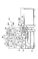
図1は、本発明の第1の実施の形態に係るシート給送装置を備えた画像形成装置の一例であるプリンタの断面図である。 FIG. 1 is a cross-sectional view of a printer that is an example of an image forming apparatus including a sheet feeding device according to a first embodiment of the present invention.
図1において、1000はプリンタであり、このプリンタ1000は、プリンタ本体1001と、プリンタ本体1001の上面に配され、原稿を読み取るスキャナ2000とを備えている。
In FIG. 1,
スキャナ2000は、走査光学系光源201、プラテンガラス202、開閉する原稿圧板203、レンズ204、受光素子(光電変換)205、画像処理部206、画像処理部206にて処理された画像処理信号を記憶するメモリ部208等を備えている。
The
そして、原稿を読み取る際には、プラテンガラス202の上に載置された不図示の原稿に走査光学系光源201によって光を照射することにより読み取るようにしている。そして、読み取った原稿像は画像処理部206により処理された後、電気的に符号化された電気信号207に変換されて作像手段たるレーザスキャナ111に伝送される。なお、画像処理部206にて処理され、符号化された画像情報を一旦メモリ部208に記憶させ、後述するコントローラ120からの信号によって、必要に応じてレーザスキャナ111に伝送することもできる。
When reading the original, the original (not shown) placed on the
プリンタ本体1001は、画像形成部1005と、シートSを給送するシート給送装置1002と、シート給送装置1002により給送されたシートSを画像形成部1005に搬送するシート搬送装置1004を備えている。また、プリンタ1000を制御するための制御手段たるコントローラ120を備えている。
The printer
なお、1003はオプションとして着脱自在なシート給送装置である大容量のペーパーデッキであり、このペーパーデッキ1003も、シートSを画像形成部1005に搬送するシート給送装置1002を備えている。
ここで、プリンタ本体側のシート給送装置1002は、プリンタ本体1001に引き出し可能に設けられたシート収納部100と、ピックアップローラ101と、フィードローラ102及びリタードローラ103とから成る分離部を備えている。なお、ペーパーデッキ側のシート給送装置1002もピックアップローラ101と、フィードローラ102及びリタードローラ103とから成る分離部を備えている。
Here, the
そして、シート収納部100内のシートSは所定のタイミングで昇降/回転するピックアップローラ101と、分離部との作用によって1枚ずつ分離給送されるようになっている。また、フィードローラ102とリタードローラ103のシート搬送方向下流側近傍には給紙センサ104が設けられており、この給紙センサ104によりシートSの通過が検出できるように構成されている。
The sheets S in the
シート搬送装置1004は、搬送ローラ対105と、レジスト前ローラ対130及びレジストローラ対110を有するレジストローラ部とを備えている。シート給送装置1002から給送されたシートSは搬送ローラ対105により、停止しているレジストローラ対110に一旦突き当てられる。
The
そして、このように停止しているレジストローラ対110に一旦突き当てられることにより、シート給送搬送時にシートSに発生する斜行が矯正され、この後、レジストローラ対110が回転することにより、シートSは画像形成部1005に搬送される。
Then, by once abutting against the resist
画像形成部1005は、感光ドラム112、レーザスキャナ111、現像器114、転写帯電器115、分離帯電器116等を備えている。そして、画像形成の際には、レーザスキャナ111からのレーザ光がミラー113によって折り返されて時計方向に回転する感光ドラム上の露光位置112aに照射されることにより、感光ドラム上に潜像が形成される。さらにこのようにして感光ドラム上に形成された潜像は、この後、現像器114によってトナー像として顕像化されるようになっている。
The
なお、レーザ光の照射位置は、コントローラ120からの制御信号により、レーザ書き込み位置制御回路を介して変更することが可能となっており、これにより感光ドラム112上の長手方向、いわゆる主走方向の潜像形成位置が変更可能となっている。
The irradiation position of the laser beam can be changed via a laser writing position control circuit by a control signal from the
感光ドラム上のトナー像は、この後、転写部112bにおいて、転写帯電器115によりシートSに転写される。さらに、このようにトナー像が転写されたシートSは、分離帯電器116により感光ドラム112から静電分離された後、搬送ベルト117により定着装置118に搬送されてトナー像の定着が行われ、この後、排出ローラ119によって排出される。また、定着装置118と排紙ローラ119の間の搬送経路中に排紙センサ120が設けられており、そこでのシートSの通過が検出できるように構成されている。
Thereafter, the toner image on the photosensitive drum is transferred to the sheet S by the
なお、本実施の形態においては、プリンタ本体1001とスキャナ2000とは別体であるが、プリンタ本体1001とスキャナ2000とが一体の場合もある。また、プリンタ本体1001はスキャナ2000と別体でも一体でも、レーザスキャナ111にスキャナ2000の処理信号を入力すれば複写機として機能し、FAXの送信信号を入力すればFAXとして機能する。さらに、パソコンの出力信号を入力すれば、プリンタとしても機能する。
In this embodiment, the printer
逆に、スキャナ2000の画像処理部206の処理信号を、他のFAXに送信すれば、FAXとして機能する。また、スキャナ2000において、原稿圧板203に変わって2点鎖線で示すような原稿自動送り装置250を装着するようにすれば、原稿を自動的に読み取ることもできる。
Conversely, if the processing signal of the
次にシート給送装置1002のシート収納部100について説明する。
Next, the
図2はシート収納部100の斜視図であり、シート収納部100はプリンタ本体1001に対し、レール19,20に沿って、矢印Bで示すシート給送方向と直交する、矢印Aに示す方向(幅方向)に引き出し可能となっている。そして、操作者がシートSをセットする場合は、プリンタ本体1001からシート収納部100を手前側(矢印A方向)へ引き出すことが可能となっている。
FIG. 2 is a perspective view of the
なお、シート収納部100には、不図示の着脱検知センサが設けられており、シート収納部100がプリンタ本体1001に装着されている状態か、もしくは引き出されている状態かを検知できるようになっている。
The
また、シート収納部100内にはシートを積載するための図1に示すリフター台16が設けられており、このリフター台16は、不図示のリフターモータによって回転するプーリ17により巻き取られるワイヤ18に吊り下げられている。そして、リフターモータを正逆転させることにより、リフター台16が昇降するようになっている。
Further, a
コントローラ120は、シートをセットするためシート収納部100がプリンタ本体1001から引き出され、これを着脱検知センサが検知すると、リフターモータを制御し、リフター台16を下限位置まで下降させるようにする。また、シート収納部100がプリンタ本体1001に装着され、これを着脱検知センサが検知すると、リフターモータを制御しリフター台16を上昇させるようにする。
The
なお、シート収納部100の上方には図1に示すように収納されているシートの上面の位置を検知するための紙面位置検知センサ15が設けられており、コントローラ120は、紙面位置検知センサ15の信号によってリフターモータの制御を行うようにしている。
A sheet surface position detection sensor 15 for detecting the position of the upper surface of the sheet stored as shown in FIG. 1 is provided above the
即ち、シート収納部100が装着されると、コントローラ120は、リフター台16が上昇するようにリフターモータを制御し、紙面位置検知センサ15によって適正な紙面高さが検知されると、リフターモータを停止させる。これにより、リフター台16に積載されたシートの紙面高さを適正な高さに維持することができる。
That is, when the
また、給紙動作に伴い、シートSが順次上から給送されていくと、紙面高さが徐々に下がっていき、紙面位置検知センサ15がOFFすると再度リフターモータをリフター台16が上昇するように制御し、常に紙面高さを一定範囲内に制御する。
Further, as the sheet S is sequentially fed from the top along with the paper feeding operation, the paper surface height gradually decreases, and when the paper surface position detection sensor 15 is turned off, the
ところで、シート収納部100には、シートSの奥行き方向の位置、即ちシートの幅方向の位置を規制する規制部材である前部サイド規制板1、後部サイド規制板2が対向して設けられている。この前部及び後部サイド規制板1,2は、シートSの奥行き方向(幅方向)のサイズに合わせシート収納部100内で幅方向に移動可能な構成となっている。
By the way, the
また、シート収納部100には、シートSの矢印Bで示すシート給送方向の後端位置を規制するための後端規制板3が設けられている。この後端規制板3は、前部及び後部サイド規制板1,2と同様にシートSの長さ方向のサイズに合わせてシート収納部100内でシート給送方向に移動可能な構成となっている。
Further, the
なお、図2において、405は固定壁であり、前部サイド規制板1は、この固定壁405に対し幅方向に移動可能に設けられている。
In FIG. 2,
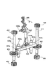
また、前部サイド規制板1の外面側(シートと当接する面とは反対側の面側)には、図3に示すように、両端近傍に前部サイド規制板1を保持する4つ(複数)の前部サイド規制板1の移動方向に延びたラックギア401〜404が上下方向に備えられている。なお、このように前部サイド規制板1の両端近傍に4つのラックギア401〜404を設けることにより、幅が広い場合でも、前部サイド規制板1はシート端規制面がシート搬送方向に対して斜めになることなく、シート端を規制することができる。 Further, on the outer surface side of the front side restricting plate 1 (the surface side opposite to the surface in contact with the seat), as shown in FIG. 3, four front side restricting plates 1 are held in the vicinity of both ends ( A plurality of rack gears 401 to 404 extending in the moving direction of the front side regulating plate 1 are provided in the vertical direction. In addition, by providing the four rack gears 401 to 404 in the vicinity of both ends of the front side regulating plate 1 in this way, even when the width is wide, the front side regulating plate 1 has a sheet end regulating surface with respect to the sheet conveying direction. The sheet edge can be regulated without being inclined.
さらに、4つのラックギア401〜404のうち、第1及び第2ラックギア401,402は左右方向(シート給送方向)において同じ位置で、上下に異なる位置に配置されている。第3及び第4ラックギア403,404も左右方向(シート給送方向)において同じ位置で、上下に異なる位置に配置されている。また、第1及び第3ラックギア401,403は略同じ高さであり、第2及び第4ラックギア402,404も略同じ高さに取り付けられている。 Further, among the four rack gears 401 to 404, the first and second rack gears 401 and 402 are arranged at the same position in the left-right direction (sheet feeding direction) and at different positions in the vertical direction. The third and fourth rack gears 403 and 404 are also arranged at the same position in the left-right direction (sheet feeding direction) and at different positions in the vertical direction. The first and third rack gears 401 and 403 have substantially the same height, and the second and fourth rack gears 402 and 404 are also attached at substantially the same height.
さらに、第1〜第4ラックギア401〜404は、シート収納部100内の固定壁405に備えられた中継ギアである第1〜第4ピニオンギア406〜409とそれぞれ噛合している。そして、前部サイド規制板1が幅方向に移動すると、これに伴い第1〜第4ラックギア401〜404と噛合している第1〜第4ピニオンギア406〜409も回転するようになっている。
Furthermore, the first to fourth rack gears 401 to 404 mesh with first to fourth pinion gears 406 to 409 that are relay gears provided on the fixed
ここで、第1ピニオンギア406と第2ピニオンギア407は第1回転軸410の上部と下部に同軸上に設けられており、第1ピニオンギア406が回転すると、第2ピニオンギア407が回転するようになっている。逆に、第2ピニオンギア407が回転すると、第1ピニオンギア406が回転するようになっている。
Here, the
一方、第3ピニオンギア408と第4ピニオンギア409は、第2回転軸411の上部と下部に同軸上に設けられており、第3ピニオンギア408が回転すると、第4ピニオンギア409が回転するようになっている。
On the other hand, the
ここで、第1回転軸410にはワンウェイクラッチ620が内周に配されたロックギアである第1ワンウェイギア601が設けられている。この第1ワンウェイギア601は、ワンウェイクラッチ620の作用により第1回転軸410が矢印AA方向に回転した場合は第1回転軸410にロックされて第1回転軸410と一体で回転し、第1回転軸410がBB方向に回転した場合には、空転する。
Here, the first
第2回転軸411には、ワンウェイクラッチ620が内周に配されたロックギアである第2ワンウェイギア602が設けられている。この第2ワンウェイギア602は、ワンウェイクラッチ620の作用により、第2回転軸411がDD方向に回転した場合は第2回転軸411にロックされて第2回転軸411と一体で回転し、第2回転軸411がCC方向に回転した場合には、空転する。
The second
なお、図3において、603は第1及び第2ワンウェイギア601,602と噛合して第1及び第2ワンウェイギア601,602をロックするロック部材であるストッパラックである。このストッパラック603の両端部には、第1及び第2ワンウェイギア601,602と噛合するギア部であるラック部603a,603bが形成されている。
In FIG. 3,
なお、ストッパラック603には固定壁405に垂設された移動軸604a,604bに挿通されるガイド部605a,605bが設けられている。そして、ストッパラック603は、固定壁405に設けられた移動軸604a,604bに沿ってガイド部605a,605bを介してスライドすることにより、上下方向(移動軸604a,604bの軸方向)に移動可能になっている。
The
また、606は固定壁405に水平に設けられた回動軸606aを中心に上下方向に回動するサイドガイドストッパつまみ、607はサイドガイドストッパつまみ606とストッパラック603とを連結するリンクである。そして、サイドガイドストッパつまみ606を上下方向に回動させることにより、ストッパラック603は、リンク607を介して上下方向に移動(昇降)するようになっている。
なお、図3において、600は、前部サイド規制板1(及び後部サイド規制板2)をシートのサイズに応じた位置に固定するための固定部である。この固定部600は、第1〜第4ラックギア401〜404、第1〜第4ピニオンギア406〜409、第1及び第2回転軸410,411と、ロック機構600Aを備えている。
In FIG. 3,
なお、このロック機構600Aは、第1及び第2ワンウェイギア601,602、第1及び第2回転軸410,411と第1及び第2ワンウェイギア601,602との相対回転を制限するワンウェイクラッチ620及びストッパラック603により構成される。そして、このロック機構600Aにより、前部サイド規制板1が規制するシートから離れる方向へ移動するときの第1及び第2回転軸410,411の回転が規制される。また、このロック機構600Aにより、前部サイド規制板1がシートに圧接する方向へ移動するときの第1及び第2回転軸410,411の回転を許容される。
The
例えば、サイドガイドストッパつまみ606を下げると、ストッパラック603は下降し、図4に示すように第1及び第2ワンウェイギア601,602とラック部603a,603bが噛合(係合)する。また、サイドガイドストッパつまみ606を上に移動させると、図5に示すように第1及び第2ワンウェイギア601,602とラック部603a,603bとの噛合が解除されるようになっている。
For example, when the side
なお、本実施の形態において、サイドガイドストッパつまみ606は、固定するための回転方向(上げた位置から下げた位置への回転方向)が、図2に示すシート収納部100の引き出し方向Aと同じ方向になるように配置されている。また、プリンタ本体1001には、サイドガイドストッパつまみ606を上げたままでシート収納部100を装着した場合、サイドガイドストッパつまみ606と当接する不図示の当接部が設けられている。
In the present embodiment, the side
これにより、サイドガイドストッパつまみ606を上げたままでシート収納部100をプリンタ本体1001に装着した場合には、サイドガイドストッパつまみ606がプリンタ本体側の不図示の当接部に当たり、下げた位置に自動的に回動するようになっている。この結果、シート収納部100を装着した際には、前部サイド規制板1は必ずロックされるようになる。
As a result, when the
また、前部サイド規制板1の内面側(後部サイド規制板2と対向する面側)下端には、図6に示すように、後部サイド規制板2との連動用のラックギア412が備えられている。このラックギア412は、シート収納部底面の略中央部に設けられたピニオンギア413と噛合っている。なお、図6において、414は後部サイド規制板2の内側(前部サイド規制板1と対向する面側)下端に設けられた連動用のラックギアであり、このラックギア414もピニオンギア413と噛合っている。
Further, as shown in FIG. 6, a
このように前部サイド規制板1のラックギア412と、後部サイド規制板2のラックギア414とをピニオンギア413と噛合させることにより、前部サイド規制板1と後部サイド規制板2とを連動させることができる。
In this way, the front side regulating plate 1 and the rear
次に、シート収納部100に、例えば、それまでよりも大きなサイズのシートを収納する場合における前部及び後部サイド規制板1,2の操作について説明する。
Next, the operation of the front and rear
この場合、操作者は、まずサイドガイドストッパつまみ606を持ち上げ、図5に示すように第1及び第2ワンウェイギア601,602と、ストッパラック603のラック部603a,603bとの噛合を解除する。次に、前部及び後部サイド規制板1,2の幅方向の間隔がシート幅より大きくなるようにする。
In this case, the operator first lifts the side
この際、図3に示すように前部サイド規制板1の上端部に設けられた上部把手部415を持って前部サイド規制板1を、後部サイド規制板2との間隔が拡がる方向(シートから離れる方向)に動かすようにする。この時、第1及び第3ラックギア401,403が、上部の第1及び第3ピニオンギア406,408に対して移動し、これにより第1及び第3ピニオンギア406,408はそれぞれ矢印AA、DD方向に回転する。
At this time, as shown in FIG. 3, the front side regulating plate 1 is held by the
このように第1及び第3ピニオンギア406,408が回転すると、その回転が、第1及び第2回転軸410,411を介して伝達され、下部の第2及び第4ピニオンギア407,409が回転し、下部の第2及び第4ラックギア402,404を動かす。なお、この時、第1及び第2回転軸410,411の動きに合わせて第1及び第2ワンウェイギア601,602は自由に回転する。
When the first and third pinion gears 406 and 408 are thus rotated, the rotation is transmitted via the first and
また、この前部サイド規制板1の移動に合わせて図6に示すラックギア412が移動し、ピニオンギア413を回転させ、さらに後部サイド規制板2に固定されたラックギア414を移動させる。これにより、後部サイド規制板2も同じように外側に移動する。
Further, the
次に、シートをセットし、前部サイド規制板1を、上部把手部415を持ってシートサイズに合わせるように内側に移動させる。そして、このように上部が移動することで第1及び第3ラックギア401,403が、第1及び第3ピニオンギア406,408に対して移動し、第1及び第3ピニオンギア406,408をそれぞれ矢印BB,CC方向に回転させる。
Next, the sheet is set, and the front side regulating plate 1 is moved inward so as to match the sheet size with the
また、このように第1及び第3ピニオンギア406,408が回転することで、第2及び第4ピニオンギア407,409が回転し、下部の第2及び第4ラックギア402,404を動かす。なお、この時も第1及び第2回転軸410,411の動きに合わせて第1及び第2ワンウェイギア601,602は自由に回転する。さらに、この前部サイド規制板1の移動に合わせて後部サイド規制板2も同じように内側に移動する。
In addition, the first and third pinion gears 406 and 408 rotate in this manner, whereby the second and fourth pinion gears 407 and 409 rotate, and the lower second and fourth rack gears 402 and 404 are moved. At this time, the first and second one-way gears 601 and 602 freely rotate in accordance with the movement of the first and second
次に、このように前部サイド規制板1及び後部サイド規制板2をシートサイズに応じた位置に移動させた後、前部サイド規制板1及び後部サイド規制板2の位置を固定するようサイドガイドストッパつまみ606を下げる。
Next, after the front side restricting plate 1 and the rear
これにより、ストッパラック603が下降し、ストッパラック603の両端に形成されたラック部603a,603bが図4に示すように第1及び第2ワンウェイギア601,602と噛合する。ここで、ストッパラック603は、移動軸604a,604bにより幅方向には移動しないようになっているので、ラック部603a,603bが噛合すると、第1及び第2ワンウェイギア601,602は回転が規制される。即ち、第1及び第2ワンウェイギア601,602はロックされる。
As a result, the
第1ワンウェイギア601がロックされると、ワンウェイクラッチ620の作用により、第1回転軸410は、前部サイド規制板1がシートを離れる方向へ移動する方向の回転であるAA方向の回転が規制される。また、第2ワンウェイギア602がロックされると、第2回転軸411は前部サイド規制板1がシートを離れる方向へ移動する方向の回転であるDD方向の回転が規制される。
When the first one-
即ち、ストッパラック603の両端に形成されたラック部603a,603bが第1及び第2ワンウェイギア601,602と噛合すると、第1及び第2回転軸410,411の、前部サイド規制板1がシートを離れる方向へ移動する方向の回転が規制される。これにより、前部サイド規制板1が、後部サイド規制板2との間隔が拡がる方向にずれるのを防ぐことができる。
That is, when the
ところで、本実施の形態において、サイドガイドストッパつまみ606の下げ操作により、ストッパラック603のラック部603a,603bが上方から第1及び第2ワンウェイギア601,602に噛合するようになっている。
By the way, in this embodiment, the
図7は、第1ワンウェイギア601と、ストッパラック603のラック部603aの構成を示す図である。なお、第2ワンウェイギア602と、ストッパラック603のラック部603bも同様の構成である。
FIG. 7 is a diagram illustrating a configuration of the first one-
第1ワンウェイギア601に対してラック部603aが上方より噛合する場合、第1ワンウェイギア601とラック部603aの歯面のサイドの面が平らでは位相がぴったり合わない限り干渉して入らない。
When the
このため、一般的にギアに対してラックを入れる場合は、互いの歯の中心線を頂きにした山形の傾斜を互いに設けるようにしている。しかし、このように構成した場合、第1ワンウェイギア601にラック部603aを噛合させる際、噛合させる際の位相によっては、ワンウェイギア601をAA方向に回転させなければ噛合できない場合と、BB方向に回転させなければ噛合できない場合が生じる。
For this reason, generally, when a rack is inserted into a gear, a mountain-shaped inclination with the center line of each tooth as the top is provided. However, with this configuration, when the
ここで、ワンウェイクラッチ620の作用により、第1ワンウェイギア601のAA方向への回転は、第1ワンウェイギア601の回転だけで済む。しかし、第1ワンウェイギア601のBB方向への回転は、ワンウェイクラッチ620の作用により第1回転軸410と一体的に行われる。
Here, due to the action of the one-
この場合、第1回転軸410とつながっている第1及び第2ピニオンギア406,407、第1及び第2ラックギア401,402を動かし、さらに前部サイド規制板1をシート側に移動させないと第1ワンウェイギア601を回転させることはできない。そして、このように第1回転軸410、第1及び第2ピニオンギア406,407、第1及び第2ラックギア401,402及び前部サイド規制板1を移動させるためには、大きな力が必要となる。
In this case, the first and second pinion gears 406 and 407, the first and second rack gears 401 and 402 connected to the
しかし、このような力をサイドガイドストッパつまみ606によって発生させることはできない。つまり、互いの歯の中心線を頂きにした山形の傾斜を設けたのでは、第1ワンウェイギア601とラック部603aの位相によっては、第1ワンウェイギア601とラック部603aとを噛合させることができない場合がある。
However, such a force cannot be generated by the side
そこで、本実施の形態において、このようにストッパラック603のラック部603a,603bと噛合する際、第1及び第2ワンウェイギア601,602は必ずAA方向、又はDD方向に回転するようにしている。
Therefore, in this embodiment, when meshing with the
このため、本実施の形態では、第1ワンウェイギア601の歯が、ワンウェイクラッチ620によって第1回転軸410が回転を規制される方向であるAA方向に向かって高くなるように、稜線607が歯面の周方向のなかで1番高くなるように傾斜させている。
For this reason, in the present embodiment, the
つまり、第1ワンウェイギア601の歯のラック部側(ロック部材側)にはAA方向に、かつAA方向下流側が高くなるように、即ちラック部側に近づく方向に傾斜した傾斜面611が設けられている。なお、説明の中での高い低いという表現は、重力方向を下(低く)、反対方向を上(高く)と定義している。
That is, the first one-
また、ラック部603aには、固定力を確保するために上下方向に延びた3本(複数)の歯が設けられている。なお、以下、この3本の歯のうち、中央の歯609を第2の歯、第2の歯609のAA方向下流側に位置する歯608を第1の歯、第2の歯609のAA方向上流側に位置する歯610を第3の歯という。
The
そして、第1〜第3の歯608,609,610は稜線608a,609a,610aが、第1回転軸410を中心とした周方向の中で1番低くなるように形成されている。つまり、この第1〜第3の歯608,609,610の第1ワンウェイギア側(ロックギア側)は、AA方向に、かつ下流側が高くなるように、即ち第1ワンウェイギア601から遠ざかる方向に傾斜した傾斜面612が設けられている。
The first to
図9は第1ワンウェイギア601、ラック部603aを上方から見たもの図である。なお、図9は、第1ワンウェイギア601の歯とラック部603aの歯の位相がずれた状態でラック部603aの歯が第1ワンウェイギア601の歯に当接する状態を示している。また、図9において、608a,609a,610aは稜線を示しているが、この稜線608a,609a,610aは上方から見えている面でなく傾斜がついているところを示している。
FIG. 9 is a view of the first one-
ここで、位相がずれていた場合、最も第1ワンウェイギア601に力が作用する第2の歯609がワンウェイギア601をAA方向に回転させようとする。しかし、このとき第3の歯610の稜線610aの傾斜が、第1ワンウェイギア601の稜線607aの傾斜よりも大きいと、稜線610aの根元側(下端側)によりワンウェイギア601のAA方向の回転が邪魔される場合がある。そこで、本実施の形態では、第3の歯610の稜線610aを稜線607cの傾斜よりも大きくなるように構成している。
Here, when the phase is shifted, the
また、第1の歯608の稜線608aの傾斜が第1ワンウェイギア601の稜線607cの傾斜よりも小さいと、稜線608aの上端側により第1ワンウェイギア601のAA方向の回転が邪魔される場合がある。そこで、本実施の形態では、図10に示すように第1の歯608の稜線608aを稜線607cの傾斜よりも大きくなるように構成している。
Further, if the inclination of the
なお、図10において、θ1は、ラック部603aの第1の歯608の第1ワンウェイギア601に近い側の稜線608aと、第1ワンウェイギア601の回転中心を法線とした面とのなす角度である。また、θ2は、第1ワンウェイギア601の歯の、ラック部に近い側の稜線607cと、第1ワンウェイギア601の回転中心を法線とした面とのなす角度である。
In FIG. 10, θ1 is an angle formed between the
つまり、本実施の形態においては、第1ワンウェイギア601の回転中心を法線とした面に対し、第1の歯608の稜線608aが成す角度θ1を、第1ワンウェイギア601の稜線607cが成す角度θ2よりも大きくしている。
That is, in the present embodiment, the
さらに、第1の歯608を他の歯609,610よりも第1ワンウェイギア側に延ばすようにしている。即ち、第1の歯608の稜線608aを、他の歯609,610の稜線609a,610aの稜線よりも、第1ワンウェイギア601に近い位置としている。
Further, the
これにより、他の歯609,610(の稜線609a,610a)が第1ワンウェイギア610の稜線607cに当接する前に、第1の歯608の稜線608aが最初に第1ワンウェイギア610の稜線607cに当接する。
Thereby, before the
そして、このように構成することにより、第1ワンウェイギア601の歯とラック部603aの位相がずれた場合でも、第1ワンウェイギア601をAA方向に回転させ、ラック部603aと噛合させることができる。この結果、サイドガイドストッパつまみ606を小さい力、即ちワンウェイギア610のみを僅かに(最高でも1歯分だけ)回転させる力で下げることで、前部サイド規制板1をほとんどガタのない状態でロックすることができる。
With this configuration, even when the teeth of the first one-
このように、ラック部603aが第1ワンウェイギア601と噛合する際、ワンウェイクラッチ620により第1回転軸410のAA方向への回転を規制することにより、シートの横ズレを生じさせることなく、前部サイド規制板1を確実に固定することができる。また、このように構成することにより、シートの横ズレもなく、力の弱い人でも操作感を損ねることなく、大きなロック力を安定的に得ることが出来る。
As described above, when the
次に、本発明の第2の実施の形態について説明する。 Next, a second embodiment of the present invention will be described.
図11は、本実施の形態に係るプリンタのシート収納部に設けられた前部サイド規制板の構成を説明する図である。なお、図11において、既述した図3と同一符号は、同一又は相当部分を示している。 FIG. 11 is a diagram illustrating the configuration of the front side regulating plate provided in the sheet storage unit of the printer according to the present embodiment. In FIG. 11, the same reference numerals as those in FIG. 3 described above indicate the same or corresponding parts.
図11において、601,601aは、第1回転軸410に設けられたロックギアである第1及び第3ワンウェイギアである。この第1及び第3ワンウェイギア601,601aには互いにロック方向の異なるワンウェイクラッチ620a,620bが内周にそれぞれ配されている。
In FIG. 11,
ここで、第3ワンウェイギア601aは、第3ワンウェイクラッチ620bの作用により第1回転軸410が矢印AA方向に回転した場合は第1回転軸410にロックされて第1回転軸410と一体で回転する。また、第1回転軸410がBB方向に回転した場合には、空転する。
Here, the third one-
また、第1ワンウェイギア601は、第1ワンウェイクラッチ620aの作用により第1回転軸410が矢印AA方向に回転した場合は空転し、第1回転軸410がBB方向に回転した場合には、第1回転軸410にロックされて回転する
Further, the first one-
また、図11において、602,602aは、第2回転軸411に設けられたロックギアである第2及び第4ワンウェイギアである。この第2及び第4ワンウェイギア601,601aには互いにロック方向の異なるワンウェイクラッチ620c,620dが内周にそれぞれ配されている。
In FIG. 11,
ここで、第4ワンウェイギア602aは、第4ワンウェイクラッチ620dの作用により、第2回転軸411がDD方向に回転した場合は第2回転軸411にロックされて第2回転軸411と一体で回転する。また、第2回転軸411がCC方向に回転した場合には、空転する。
Here, the fourth one-
また、第2ワンウェイギア602は、第2ワンウェイクラッチ620cの作用により、第2回転軸411がCC方向に回転した場合は第2回転軸411にロックされて第2回転軸411と一体で回転し、第2回転軸411がDD方向に回転した場合には、空転する。
Also, the second one-
なお、図11において、603は第1〜第4ワンウェイギア601,601a,602,602aと噛合して第1〜第4ワンウェイギア601,601a,602,602aをロックするロック部材であるストッパラックである。
In FIG. 11,
ストッパラック603の両端部には、第1及び第3ワンウェイギア601,601aと噛合するギア部であるラック部603a,603bと、第2及び第4ワンウェイギア602,602aと噛合するギア部であるラック部603c,604dが形成されている。
At both ends of the
ここで、本実施の形態においては、第1ワンウェイギア601よりも第3ワンウェイギア601aの方が大径となっている。また、第2ワンウェイギア602よりも第4ワンウェイギア602aの方が大径となっている。
Here, in the present embodiment, the third one-
そして、このように径の異なる第1及び第3ワンウェイギア601,601aと噛合するため、第1ラック部603aの方が第2ラック部603bに比べて側方に突出して形成されている。また、径の異なる第2及び第4ワンウェイギア602,602aと噛合するため、第3ラック部603cの方が第4ラック部603dに比べて側方に突出して形成されている。
In order to mesh with the first and third one-way gears 601 and 601a having different diameters as described above, the
なお、ストッパラック603には固定壁405に垂設された移動軸604a,604bに挿通されるガイド部605a,605bが設けられている。そして、ストッパラック603は、固定壁405に設けられた移動軸604a,604bに沿ってガイド部605a,605bを介してスライドすることにより、上下方向(移動軸604a,604bの軸方向)に移動可能になっている。
The
なお、図11において、600は、前部サイド規制板1(及び後部サイド規制板2)をシートのサイズに応じた位置に固定するための固定部である。この固定部600は、第1〜第4ラックギア401〜404、第1〜第4ピニオンギア406〜409、第1及び第2回転軸410,411と、ロック機構600Aを備えている。
In FIG. 11,
なお、ロック機構600Aは、ワンウェイギア601,601a,602,602a、回転軸410,411とワンウェイギア601,601a,602,602aとの相対回転を制限するワンウェイクラッチ620及びストッパラック603により構成される。
The
そして、このロック機構600Aにより、前部サイド規制板1が規制するシートから離れる方向へ移動するときの第1及び第2回転軸410,411の回転が規制される。また、このロック機構600Aにより、前部サイド規制板1がシートに圧接する方向へ移動するときの第1及び第2回転軸410,411の回転も規制される。
The
例えば、サイドガイドストッパつまみ606を下げると、ストッパラック603が下降し、図12に示すように第1及び第3ワンウェイギア601,601aと、ストッパラック603の一端に設けられた第1及び第2ラック部603a,603bが噛合する。また、第2及び第4ワンウェイギア602,602aとストッパラック603の他端に設けられた第3及び第4ラック部603c,603dが噛合(係合)する。
For example, when the side
一方、サイドガイドストッパつまみ606を上に移動させると、図13及び図14に示すように第1及び第3ワンウェイギア601,601aと、ストッパラック603の第1及び第2ラック部603a,603bとの噛合が解除される。また、第2及び第4ワンウェイギア602,602aと、ストッパラック603の第3及び第4ラック部603c,603dとの噛合が解除されるようになっている。
On the other hand, when the side
次に、シート収納部100に、例えば、それまでよりも大きなサイズのシートを収納する場合における前部及び後部サイド規制板1,2の操作について説明する。
Next, the operation of the front and rear
この場合、操作者は、まずサイドガイドストッパつまみ606を持ち上げ、図13及び図14に示すように第1〜第4ワンウェイギア601,601a,602,602aと、ストッパラック603の第1〜第4ラック部603a〜603dとの噛合を解除する。次に、前部及び後部サイド規制板1,2の幅方向の間隔がシート幅より大きくなるようにする。
In this case, the operator first lifts the side
この際、図11に示すように前部サイド規制板1の上端部に設けられた上部把手部415を持って前部サイド規制板1を、後部サイド規制板2との間隔が拡がる方向(シートから離れる方向)に動かすようにする。この時、第1及び第3ラックギア401,403が、上部の第1及び第3ピニオンギア406,408に対して移動し、これにより第1及び第3ピニオンギア406,408はそれぞれ矢印AA、DD方向に回転する。
At this time, as shown in FIG. 11, the front side regulating plate 1 is held by the
このように第1及び第3ピニオンギア406,408が回転すると、その回転が、第1及び第2回転軸410,411を介して伝達され、下部の第2及び第4ピニオンギア407,409が回転し、下部の第2及び第4ラックギア402,404を動かす。なお、この時、第1回転軸410,411の動きに合わせて第1〜第4ワンウェイギア601,601a,602,602aは自由に回転する。
When the first and third pinion gears 406 and 408 are thus rotated, the rotation is transmitted via the first and
また、この前部サイド規制板1の移動に合わせて既述した図6に示すラックギア412が移動し、ピニオンギア413を回転させ、さらに後部サイド規制板2に固定されたラックギア414を移動させる。これにより、後部サイド規制板2も同じように外側に移動する。
Further, the
次に、シートをセットし、前部サイド規制板1を、上部把手部415を持ってシートサイズに合わせるように内側に移動させる。そして、このように上部が移動することで第1及び第3ラックギア401,403が、第1及び第3ピニオンギア406,408に対して移動し、第1及び第3ピニオンギア406,408をそれぞれ矢印BB,CC方向に回転させる。
Next, the sheet is set, and the front side regulating plate 1 is moved inward so as to match the sheet size with the
また、このように第1及び第3ピニオンギア406,408が回転することで、第2及び第4ピニオンギア407,409が回転し、下部の第2及び第4ラックギア402,404を動かす。なお、この時も第1及び第2回転軸410,411の動きに合わせて第1〜第4ワンウェイギア601,601a,602,602aは自由に回転する。さらに、この前部サイド規制板1の移動に合わせて後部サイド規制板2も同じように内側に移動する。
In addition, the first and third pinion gears 406 and 408 rotate in this manner, whereby the second and fourth pinion gears 407 and 409 rotate, and the lower second and fourth rack gears 402 and 404 are moved. At this time, the first to fourth one-way gears 601, 601 a, 602, and 602 a freely rotate in accordance with the movement of the first and second
次に、このように前部サイド規制板1及び後部サイド規制板2をシートサイズに応じた位置に移動させた後、前部サイド規制板1及び後部サイド規制板2の位置を固定するようサイドガイドストッパつまみ606を下げる。
Next, after the front side restricting plate 1 and the rear
これにより、ストッパラック603が下降し、ストッパラック603の両端に形成された第1〜第4ラック部603a〜603dが図12に示すように第1〜第4ワンウェイギア601,601a,602,602aと噛合する。
As a result, the
ここで、ストッパラック603は、移動軸604a,604bにより幅方向には移動しないようになっているので、第1〜第4ラック部603a〜604dが噛合すると、第1〜第4ワンウェイギア601,601a,602,602aは回転が規制される。即ち、第1〜第4ワンウェイギア601,601a,602,602aはロックされ、回転が規制される。
Here, since the
ここで、第3ワンウェイギア601aは、第3ワンウェイクラッチ620bにより、第3ワンウェイギア601aがBB方向(軸410がAA方向)に回転しようとすると軸410にロックされる。なお、第3ワンウェイギア601aのAA方向の回転は許容される。そして、このように第3ワンウェイギア601aがロックされると、第3ワンウェイクラッチ620bの作用により、第1回転軸410の、前部サイド規制板1がシートを離れる方向へ移動する方向の回転であるAA方向の回転が規制される。
Here, the third one-
また、第4ワンウェイギア602aは、第4ワンウェイクラッチ620dにより、第4ワンウェイギア602aがCC方向(軸411がDD方向)に回転しようとすると軸411にロックされる。なお、第4ワンウェイギア602aのDD方向の回転は許容される。そして、このように第4ワンウェイギア602aがロックされると、第4ワンウェイクラッチ620dの作用により、第2回転軸411は、前部サイド規制板1がシートを離れる方向へ移動する方向の回転であるDD方向の回転が規制される。
The fourth one-
即ち、第3及び第4ワンウェイギア601a,602aがストッパラック603に形成された第2及び第4ラック部603b,603dと噛合すると、第1及び第2回転軸411の、前部サイド規制板1がシートを離れる方向へ移動する方向の回転が規制される。これにより、前部サイド規制板1に後部サイド規制板2との間隔が拡がる方向に力が加わった場合でも、軸410,411が回転せず、前部サイド規制板1が、後部サイド規制板2との間隔が拡がる方向である外側方向(A方向)にずれるのを防ぐことができる。
That is, when the third and fourth one-
また、第1ワンウェイギア601は、第1ワンウェイクラッチ620aにより、第1ワンウェイギア601がAA方向(軸410がBB方向)に回転しようとすると軸410にロックされる。そして、このように第1ワンウェイギア601がロックされると、第1ワンウェイクラッチ620aの作用により、第1回転軸410は、前部サイド規制板1がシート側へ移動する方向の回転であるBB方向の回転が規制される。なお、第1ワンウェイギア602aのBB方向の回転は許容される。
The first one-
また、第2ワンウェイギア602は、第2ワンウェイクラッチ620cにより、第2ワンウェイギア602がDD方向(軸411がCC方向)に回転しようとすると軸411にロックされる。なお、第2ワンウェイギア602のCC方向の回転は許容される。そして、このように第2ワンウェイギア602がロックされると、第2ワンウェイクラッチ620cの作用により、第2回転軸411は前部サイド規制板1がシート側へ移動する方向の回転であるCC方向の回転が規制される。
The second one-
即ち、第1及び第2ワンウェイギア601,602がストッパラック603の両端に形成された第1及び第3ラック部603a,603cと噛合すると、第1及び第2回転軸411の、前部サイド規制板1がシート側へ移動する方向の回転が規制される。これにより、前部サイド規制板1にシート側へ移動する方向の力が加わった場合でも、軸410,411が回転せず、前部サイド規制板1が、後部サイド規制板2との間隔が狭くなる方向である内側方向(Aと反対方向)にずれるのを防ぐことができる。
That is, when the first and second one-way gears 601 and 602 mesh with the first and
なお、このように前部サイド規制板1をロックすることにより、例えばシートが満載状態のシート収納部100を勢い良くプリンタ本体1001に装着しても、シートのイナーシャで前部及び後部サイド規制板1,2が動かないようにすることができる。
By locking the front side restricting plate 1 in this way, for example, even if the
また、セットするシートが少量のときに、シート収納部100を勢い良くプリンタ本体1001に装着したときに、前部サイド規制板自体のイナーシャによって前部サイド規制板1が動かないようにすることができる。なお、第1〜第4ワンウェイギア601,601a,602,602aに内設するワンウェイクラッチのトルク値については、このような事情を鑑みて、必要なトルク値を設定すれば良い。
In addition, when the number of sheets to be set is small, when the
ところで、本実施の形態において、サイドガイドストッパつまみ606の下げ操作により、ストッパラック603の第1〜第4ラック部603a〜603dが上方から第1〜第4ワンウェイギア601,601a,602,602aに噛合するようになっている。
By the way, in the present embodiment, when the side
図15は、第1及び第3ワンウェイギア601,601aと、ストッパラック603の第1及び第2ラック部603a,603bの構成を示す図である。なお、第2及び第4ワンウェイギア602,602aと、ストッパラック603の第3及び第4ラック部603c,603dも同様の構成である。
FIG. 15 is a diagram showing the configuration of the first and third one-way gears 601 and 601a and the first and
ここで、例えば第3ワンウェイギア601aに対して第2ラック部603bが上方より噛合する場合、第3ワンウェイギア601aと第2ラック部603bの歯面のサイドの面が平らでは位相がぴったり合わない限り干渉して入らない。なお、これは他の第4ワンウェイギア602aと、第4ラック部603dも同様である。
Here, for example, when the
このため、一般的にギアに対してラックを入れる場合は、互いの歯の中心線を頂きにした山形の傾斜を互いに設けるようにしている。しかし、この場合、第3ワンウェイギア601aに第2ラック部603bを噛合させる際、噛合させる際の位相によっては、第3ワンウェイギア601aをAA方向に回転させなければ噛合できない場合と、BB方向に回転させなければ噛合できない場合が生じる。
For this reason, generally, when a rack is inserted into a gear, a mountain-shaped inclination with the center line of each tooth as the top is provided. However, in this case, when the
ここで、第3ワンウェイクラッチ620bの作用により、第3ワンウェイギア601aのAA方向への回転は、第3ワンウェイギア601aの回転だけで済む。しかし、第3ワンウェイギア601aのBB方向への回転は、第3ワンウェイクラッチ620bの作用により第1回転軸410と一体的に行われる。
Here, due to the action of the third one-way clutch 620b, the rotation of the third one-
この場合、第1回転軸410とつながっている第1及び第2ピニオンギア406,407、第1及び第2ラックギア401,402を動かし、さらに前部サイド規制板1をシート側に移動させないと第3ワンウェイギア601aを回転させることはできない。そして、このように第1回転軸410、第1及び第2ピニオンギア406,407、第1及び第2ラックギア401,402及び前部サイド規制板1を移動させるためには、大きな力が必要となる。
In this case, the first and second pinion gears 406 and 407, the first and second rack gears 401 and 402 connected to the
しかし、このような力をサイドガイドストッパつまみ606によって発生させることはできない。つまり、互いの歯の中心線を頂きにした山形の傾斜を設けたのでは、第3ワンウェイギア601aと第2ラック部603bの位相によっては、第3ワンウェイギア601aと第2ラック部603bとを噛合させることができない場合がある。
However, such a force cannot be generated by the side
そこで、本実施の形態において、このようにストッパラック603の第2ラック部603bと噛合する際、第3ワンウェイギア601aは必ずAA方向に回転するようにしている。なお、第4ワンウェイギア602aが第4ラック部603dと噛合する際には、第4ワンウェイギア602aは必ずDD方向に回転するようにしている
Therefore, in the present embodiment, when meshing with the
このため、図15に示すように第3ワンウェイギア601aの歯が、ワンウェイクラッチ620bによって第1回転軸410が回転を規制される方向であるAA方向に向かって高くなるように稜線607が歯面の周方向のなかで1番高くなるように傾斜させている。
Therefore, as shown in FIG. 15, the
つまり、第3ワンウェイギア601aの歯のラック部側(ロック部材側)にはAA方向に、かつAA方向下流側が高くなるように、即ちラック部側に近づく方向に傾斜した傾斜面611が設けられている。
That is, an
また、第2ラック部603bには、図16に示すように固定力を確保するために上下方向に延びた3本(複数)の歯が設けられている。なお、以下、この3本の歯のうち、中央の歯609を第2の歯、第2の歯609のAA方向下流側に位置する歯608を第1の歯、第2の歯609のAA方向上流側に位置する歯610を第3の歯という。
In addition, as shown in FIG. 16, the
そして、第1〜第3の歯608,609,610は稜線608a,609a,610aが、第1回転軸410を中心とした周方向の中で1番低くなるように形成されている。つまり、この第1〜第3の歯608,609,610の第3ワンウェイギア側(ロックギア側)は、AA方向に、かつ下流側が高くなるように、即ち第3ワンウェイギア601aから遠ざかる方向に傾斜した傾斜面612が設けられている。
The first to
ここで、第3ワンウェイギア601aと第2ラック部603bとの関係は、既述した図9と同様である。即ち、第3の歯610の稜線610aの傾斜が、第3ワンウェイギア601aの稜線607aの傾斜よりも大きいと、稜線610aの根元側(下端側)により第3ワンウェイギア601aのAA方向の回転が邪魔される場合がある。このため、本実施の形態では、第3の歯610の稜線610aを稜線607cの傾斜よりも大きくなるように構成している。
Here, the relationship between the third one-
また、第1の歯608の稜線608aの傾斜が第3ワンウェイギア601aの稜線607cの傾斜よりも小さいと、稜線608aの上端側により第3ワンウェイギア601aのAA方向の回転が邪魔される場合がある。そこで、本実施の形態では、既述した図10に示すように第1の歯608の稜線608aを稜線607cの傾斜よりも大きくなるように構成している。
Further, if the inclination of the
そして、このように構成することにより、第3ワンウェイギア601aの歯と第2ラック部603bの位相がずれた場合でも、第3ワンウェイギア601aをAA方向に回転させ、第2ラック部603bと噛合させることができる。
With this configuration, even when the teeth of the third one-
一方、第1ワンウェイギア601に第1ラック部603aを噛合させる際も、噛合させる際の位相によっては、第1ワンウェイギア601をAA方向に回転させなければ噛合できない場合と、BB方向に回転させなければ噛合できない場合が生じる。
On the other hand, when the
ここで、第1ワンウェイクラッチ620aの作用により、第1ワンウェイギア601のAA方向への回転は、第1ワンウェイギア601の回転だけで済むが、第1ワンウェイギア601のBB方向への回転は、既述したように大きな力が必要となる。
Here, due to the action of the first one-way clutch 620a, the rotation of the first one-
そこで、本実施の形態において、このようにストッパラック603の第1ラック部603aと噛合する際、第1ワンウェイギア601は必ずAA方向に回転するようにしている。なお、同様に、第2ワンウェイギア602はDD方向に回転するようにしている。
Therefore, in the present embodiment, when meshing with the
このため、本実施の形態では、図15に示すように第1ワンウェイギア601の歯が、BB方向に向かって高くなるように、稜線607aが歯面の周方向のなかで1番高くなるように傾斜させている。
For this reason, in the present embodiment, as shown in FIG. 15, the
つまり、第1ワンウェイギア601の歯のラック部側(ロック部材側)にはBB方向に、かつBB方向下流側が高くなるように、即ちラック部側から離れる方向に傾斜した傾斜面611aが設けられている。
That is, an
また、第1ラック部603aには、図16に示すように固定力を確保するために上下方向に延びた3本(複数)の歯が設けられている。なお、以下、この3本の歯のうち、中央の歯619を第2の歯、第2の歯619のBB方向下流側に位置する歯618を第1の歯、第2の歯609のBB方向上流側に位置する歯620を第3の歯という。
Further, as shown in FIG. 16, the
そして、第1〜第3の歯618,619,620は稜線618a,619a,620aが、第1回転軸410を中心とした周方向の中で1番低くなるように形成されている。つまり、この第1〜第3の歯618,619,620の第1ワンウェイギア側(ロックギア側)は、BB方向に、かつ下流側が高くなるように、即ち第1ワンウェイギア601から離れる方向に傾斜した傾斜面621が設けられている。
The first to
図17は第1ワンウェイギア601及び第1ラック部603aを上方から見たものである。なお、図17は、第1ワンウェイギア601の歯と第1ラック部603aの歯の位相がずれた状態で第1ラック部603aの歯が第1ワンウェイギア601の歯に当接する状態を示している。
FIG. 17 shows the first one-
また、図17において、618a,619a,620aは第1〜第3の歯618,619,620の稜線を示しているが、この稜線618a,619a,620aは上方から見えている面でなく傾斜がついているところを示している。さらに、図17において、614a〜614c、615a〜615cは第1ワンウェイギア601の歯の稜線を示している。
In FIG. 17, 618a, 619a, and 620a indicate ridge lines of the first to
ここで、歯がずれていた場合、第1ラック部603aの第3の歯620の稜線620aに第1ワンウェイギア601の歯の稜線614cが当接する時、稜線620aの傾斜が稜線614cの傾斜よりも大きかった場合、稜線620aの根元側が邪魔になる。この場合、第1ワンウェイギア602がBB方向に回転するのを邪魔してしまう。
Here, when the teeth are displaced, when the
また、第1ラック部603aの第1の歯618の稜線618aに第1ワンウェイギア601の歯の稜線614aが当接する時、稜線618aの傾斜が稜線614aの傾斜よりも小さかった場合、稜線618aの先端側が邪魔になる。この場合、第1ワンウェイギア602がBB方向に回転するのを邪魔してしまう。
In addition, when the
そこで、本実施の形態では、第1ラック部603aの第1の歯618の稜線618aを第1ワンウェイギア601の歯の稜線614aの傾斜よりも大きくなるように構成している。さらに、図17に示すように第1ラック部603aの第1〜第3の歯618〜620の稜線618a,619a,620aの中で、第1の歯618の稜線618aが最初にワンウェイギア602の稜線614aに当接させるようにしている。
Therefore, in the present embodiment, the
そして、このように構成することにより、第1ワンウェイギア601の歯と第1ラック部603aの位相がずれた場合でも、第1ワンウェイギア601をAA方向に回転させ、第1ラック部603aと噛合させることができる。
With this configuration, even when the teeth of the first one-
この結果、サイドガイドストッパつまみ606を小さい力、即ち第1及び第3ワンウェイギア601,601aのみを僅かに(最高でも1歯分だけ)回転させる力で下げることで、前部サイド規制板1をほとんどガタのない状態でロックすることができる。なお、第2及び第4ワンウェイギア602,602aと第3及び第4ラック部603c,603dについても、上述と同様の構成を実施している。
As a result, the front side regulating plate 1 is lowered by lowering the side
このように、本実施の形態においては、第1〜第4ラック部603a〜603dが第1〜第4ワンウェイギア601,601a,602,602aと噛合すると、ワンウェイクラッチ620により第1及び第2回転軸410,411の回転を規制することができる。つまり、前部サイド規制板1(及び後部サイド規制板2)の移動に伴って回転する第1及び第2回転軸410,411の回転をロック機構600Aにより規制することができる。
Thus, in the present embodiment, when the first to
これにより、前部サイド規制板1(及び後部サイド規制板2)の、規制するシートから離れる方向及び規制するシートに圧接する方向への移動の両方を規制することができる。この結果、シートの横ズレを生じさせることなく、前部サイド規制板1(及び後部サイド規制板2)を確実に固定することができる。また、このように構成することにより、シートの横ズレもなく、力の弱い人でも操作感を損ねることなく、大きなロック力を安定的に得ることが出来る。 Accordingly, it is possible to restrict both the movement of the front side regulating plate 1 (and the rear side regulating plate 2) in the direction away from the regulating sheet and in the direction in pressure contact with the regulating sheet. As a result, the front side restricting plate 1 (and the rear side restricting plate 2) can be reliably fixed without causing a lateral shift of the seat. In addition, with such a configuration, a large locking force can be stably obtained without any lateral displacement of the seat and without damaging the feeling of operation even by a weak person.
また、本実施の形態では、既述したように上側に位置する第1及び第2ワンウェイギア601,602より、下側に位置する第3及び第4ワンウェイギア601a,602aを大径のギアとしている。
Further, in the present embodiment, as described above, the third and fourth one-
そして、このように大径のワンウェイギア601a,602aを下方に配することにより、ストッパラック605を図12に示すロック状態から、上へ移動させて図13及び図14に示すアンロック状態とするときの移動量を必要最小限に抑えることができる。この結果、プリンタ1000の小型化が可能になる。
By disposing the large-diameter one-
なお、これまで説明したシート給送装置1002は、ローラによりシートを給送する構成であったが、他の例えばエアによりシートを給送する方式のシート給送装置にも適用することができる。また、これまでの説明では、前部及び後部サイド規制板を同時に移動させる構成について述べてきたが、移動可能なサイド規制板を片側のみに配置するようにした場合でも適用することができる。
Note that the
さらに、これまでの説明では、前部サイド規制板をロックするようにしているが、後部サイド規制板をロックするようにしても良く、また前部及び後部サイド規制板の両方ともに固定させるようにしても良い。 Further, in the above description, the front side restriction plate is locked. However, the rear side restriction plate may be locked, and both the front and rear side restriction plates may be fixed. May be.
1 前部サイド規制板
2 後部サイド規制板
100 シート収納部
401〜404 第1〜第4ラックギア
405 固定壁
406〜409 第1〜第4ピニオンギア
410 第1回転軸
411 第2回転軸
600 固定部
600A ロック機構
601 第1ワンウェイギア
602 第2ワンウェイギア
601a 第3ワンウェイギア
602a 第4ワンウェイギア
603 ストッパラック
603a〜603d 第1〜第4ラック部
620 ワンウェイクラッチ
620a〜620d 第1〜第ワンウェイクラッチ
1000 プリンタ
1002 シート給送装置
1005 画像形成部
S シート
DESCRIPTION OF SYMBOLS 1 Front
Claims (16)
前記固定部は、
前記規制部材のシートと当接する面と反対側の面に設けられ、前記規制部材の移動方向に延びた複数のラックギアと、
前記複数のラックギアとそれぞれ噛合する複数の中継ギアと、
前記複数の中継ギアが同軸上に設けられた回転軸と、
前記規制部材が規制するシートから離れる方向へ移動するときの前記回転軸の回転を規制し、前記規制部材が規制するシートに圧接する方向へ移動するときの前記回転軸の回転を許容するロック機構と、
を備えたことを特徴とするシート給送装置。 A regulating member that is provided in the sheet storage unit so as to be movable in a width direction orthogonal to the sheet feeding direction, and that regulates a position of the sheet in the width direction; In a sheet feeding apparatus that feeds a sheet whose position in the width direction is regulated by the regulating member,
The fixing part is
A plurality of rack gears provided on a surface opposite to the surface of the restricting member in contact with the sheet, and extending in a moving direction of the restricting member;
A plurality of relay gears respectively meshing with the plurality of rack gears;
A rotating shaft provided coaxially with the plurality of relay gears;
A lock mechanism that restricts rotation of the rotating shaft when moving in a direction away from the sheet regulated by the regulating member, and allows rotation of the rotating shaft when moved in a direction in pressure contact with the sheet regulated by the regulating member When,
A sheet feeding apparatus comprising:
前記回転軸に設けられたロックギアと、
前記ロックギアと噛合して前記ロックギアを固定するギア部を有するロック部材と、
前記回転軸と前記ロックギアとの相対回転を制限するワンウェイクラッチと、
を備えていることを特徴とする請求項1に記載のシート給送装置。 The locking mechanism is
A lock gear provided on the rotating shaft;
A lock member having a gear portion that meshes with the lock gear and fixes the lock gear;
A one-way clutch that restricts relative rotation between the rotation shaft and the lock gear;
The sheet feeding apparatus according to claim 1, further comprising:
前記固定部は、
前記規制部材のシートと当接する面と反対側の面に設けられ、前記規制部材の移動方向に延びた複数のラックギアと、
前記複数のラックギアとそれぞれ噛合する複数の中継ギアと、
前記複数の中継ギアが同軸上に設けられ、前記規制部材の移動に伴って回転する回転軸と、
前記規制部材の、規制するシートから離れる方向及び規制するシートに圧接する方向への移動の両方を規制するよう前記回転軸の回転を規制するロック機構と、を備えたことを特徴とするシート給送装置。 A regulating member that is provided in the sheet storage unit so as to be movable in a width direction orthogonal to the sheet feeding direction, and that regulates a position of the sheet in the width direction; In a sheet feeding apparatus that feeds a sheet whose position in the width direction is regulated by the regulating member,
The fixing part is
A plurality of rack gears provided on a surface opposite to the surface of the restricting member in contact with the sheet, and extending in a moving direction of the restricting member;
A plurality of relay gears respectively meshing with the plurality of rack gears;
The plurality of relay gears are provided on the same axis, and a rotating shaft that rotates as the regulating member moves,
A sheet feeding mechanism comprising: a lock mechanism that regulates rotation of the rotating shaft so as to regulate both movement of the regulating member in a direction away from the regulating sheet and in a direction in pressure contact with the regulating sheet. Feeding device.
前記回転軸に設けられた複数のロックギアと、
前記複数のロックギアと噛合して前記ロックギアを固定するギア部を有するロック部材と、
前記回転軸と前記複数のロックギアとの間にそれぞれ設けられ、前記回転軸と前記複数のロックギアとの相対回転を制限するロック方向が異なるワンウェイクラッチと、
を備えていることを特徴とする請求項8に記載のシート給送装置。 The locking mechanism is
A plurality of lock gears provided on the rotating shaft;
A lock member having a gear portion that meshes with the plurality of lock gears and fixes the lock gear;
A one-way clutch provided between the rotation shaft and the plurality of lock gears, and having different lock directions for restricting relative rotation between the rotation shaft and the plurality of lock gears;
The sheet feeding apparatus according to claim 8, further comprising:
Priority Applications (1)
| Application Number | Priority Date | Filing Date | Title |
|---|---|---|---|
| JP2007211059A JP5004718B2 (en) | 2007-04-12 | 2007-08-13 | Sheet feeding apparatus and image forming apparatus |
Applications Claiming Priority (3)
| Application Number | Priority Date | Filing Date | Title |
|---|---|---|---|
| JP2007105365 | 2007-04-12 | ||
| JP2007105365 | 2007-04-12 | ||
| JP2007211059A JP5004718B2 (en) | 2007-04-12 | 2007-08-13 | Sheet feeding apparatus and image forming apparatus |
Publications (3)
| Publication Number | Publication Date |
|---|---|
| JP2008280175A JP2008280175A (en) | 2008-11-20 |
| JP2008280175A5 JP2008280175A5 (en) | 2011-06-23 |
| JP5004718B2 true JP5004718B2 (en) | 2012-08-22 |
Family
ID=39852998
Family Applications (1)
| Application Number | Title | Priority Date | Filing Date |
|---|---|---|---|
| JP2007211059A Active JP5004718B2 (en) | 2007-04-12 | 2007-08-13 | Sheet feeding apparatus and image forming apparatus |
Country Status (2)
| Country | Link |
|---|---|
| US (2) | US7900911B2 (en) |
| JP (1) | JP5004718B2 (en) |
Families Citing this family (15)
| Publication number | Priority date | Publication date | Assignee | Title |
|---|---|---|---|---|
| DE102004002646A1 (en) * | 2004-01-17 | 2005-08-04 | Nexpress Solutions Llc | Device for aligning a stack of sheets |
| JP5207995B2 (en) * | 2009-01-20 | 2013-06-12 | キヤノン株式会社 | Sheet feeding apparatus and image forming apparatus |
| JP5335456B2 (en) * | 2009-01-29 | 2013-11-06 | キヤノン株式会社 | Unit drawing apparatus, sheet feeding apparatus, and image forming apparatus |
| US20110298175A1 (en) * | 2010-06-04 | 2011-12-08 | Toshiba Tec Kabushiki Kaisha | Paper feeding device |
| CN102336341B (en) * | 2010-07-21 | 2014-04-02 | 株式会社理光 | Paper feeder and image forming device using same |
| JP5751821B2 (en) | 2010-12-17 | 2015-07-22 | キヤノン株式会社 | Sheet feeding apparatus and image forming apparatus |
| JP5398757B2 (en) | 2011-02-14 | 2014-01-29 | 京セラドキュメントソリューションズ株式会社 | Paper feeding device and image forming apparatus using the same |
| US8800214B2 (en) * | 2011-05-06 | 2014-08-12 | Uni-Systems, Llc | Automated covering system |
| CN102954021A (en) * | 2011-08-24 | 2013-03-06 | 鸿富锦精密工业(深圳)有限公司 | System and method for controlling fans |
| JP5868365B2 (en) | 2013-09-18 | 2016-02-24 | キヤノン株式会社 | Image forming apparatus |
| JP5900752B2 (en) * | 2013-10-15 | 2016-04-06 | コニカミノルタ株式会社 | Paper feeding device and image forming apparatus |
| JP2016137983A (en) * | 2015-01-29 | 2016-08-04 | キヤノン株式会社 | Sheet feeding device and image formation device equipped with the same |
| US9604802B1 (en) * | 2016-03-04 | 2017-03-28 | Lexmark International, Inc. | Removable media tray having a media restraint with translating and pivoting latching cams operable without the use of pinching |
| US9663312B1 (en) * | 2016-03-04 | 2017-05-30 | Lexmark International, Inc. | Removable media tray having a media restraint with a latching plunger operable without the use of pinching |
| JP6519512B2 (en) * | 2016-03-30 | 2019-05-29 | 京セラドキュメントソリューションズ株式会社 | Optional equipment |
Family Cites Families (8)
| Publication number | Priority date | Publication date | Assignee | Title |
|---|---|---|---|---|
| JPH0632466A (en) * | 1992-07-16 | 1994-02-08 | Ricoh Co Ltd | Paper feeding device |
| JPH09110193A (en) | 1995-10-19 | 1997-04-28 | Ricoh Co Ltd | Paper feed cassette |
| JPH10265060A (en) | 1997-03-21 | 1998-10-06 | Canon Inc | Sheet storing device and image forming device |
| JP3906886B2 (en) * | 1999-07-02 | 2007-04-18 | リコープリンティングシステムズ株式会社 | Sheet storage device |
| JP4261826B2 (en) | 2002-06-12 | 2009-04-30 | キヤノン株式会社 | Image forming apparatus |
| JP2004018158A (en) * | 2002-06-14 | 2004-01-22 | Hitachi Printing Solutions Ltd | Paper hopper of printer |
| DE102004002646A1 (en) * | 2004-01-17 | 2005-08-04 | Nexpress Solutions Llc | Device for aligning a stack of sheets |
| JP4794954B2 (en) | 2005-09-13 | 2011-10-19 | キヤノン株式会社 | Image heating device |
-
2007
- 2007-08-13 JP JP2007211059A patent/JP5004718B2/en active Active
-
2008
- 2008-04-04 US US12/098,060 patent/US7900911B2/en not_active Expired - Fee Related
-
2011
- 2011-01-31 US US13/017,525 patent/US8066277B2/en not_active Expired - Fee Related
Also Published As
| Publication number | Publication date |
|---|---|
| US8066277B2 (en) | 2011-11-29 |
| US20080251996A1 (en) | 2008-10-16 |
| US20110127715A1 (en) | 2011-06-02 |
| US7900911B2 (en) | 2011-03-08 |
| JP2008280175A (en) | 2008-11-20 |
Similar Documents
| Publication | Publication Date | Title |
|---|---|---|
| JP5004718B2 (en) | Sheet feeding apparatus and image forming apparatus | |
| JP5433177B2 (en) | Paper discharge device and image forming apparatus | |
| JP6760219B2 (en) | Sheet feeding device and image forming device equipped with it | |
| JP2009296530A (en) | Image processing apparatus | |
| JP6984159B2 (en) | Sheet transfer device | |
| JP6047595B2 (en) | Paper feeding device, and image reading device and image forming apparatus provided with the same | |
| JP2015027913A (en) | Paper feeder, image reader with paper feeder, and image formation device with the image reader | |
| JP2008081295A (en) | Paper feeder | |
| JP2012246122A (en) | Sheet conveying apparatus, image reading apparatus, and image forming apparatus | |
| JP2005225602A (en) | Recording medium supply device, and image forming device | |
| JP5207995B2 (en) | Sheet feeding apparatus and image forming apparatus | |
| JP2002220122A (en) | Paper feeding device | |
| JP4709049B2 (en) | Sheet feeding apparatus and image forming apparatus using the same | |
| JP4748569B2 (en) | Tray apparatus, sheet processing apparatus, and image forming apparatus | |
| JP2018184267A (en) | Sheet transport device | |
| JP6455479B2 (en) | Coupling mechanism, sheet feeding apparatus including the same, and image forming apparatus | |
| JP2007261698A (en) | Sheet conveying device and image reading device provided therewith | |
| JP3176198B2 (en) | Drive transmission device and sheet feeding device | |
| JP6540042B2 (en) | Paper feeder | |
| JP5496273B2 (en) | Paper discharge device and image forming apparatus | |
| JP2007261784A (en) | Sheet feeding device and image forming device using it | |
| JP5931244B2 (en) | Sheet stacking device | |
| JP5740498B2 (en) | Paper discharge device and image forming apparatus | |
| JP2006182463A (en) | Sheet feeder and its control method | |
| JP2019085204A (en) | Image forming device |
Legal Events
| Date | Code | Title | Description |
|---|---|---|---|
| A621 | Written request for application examination |
Free format text: JAPANESE INTERMEDIATE CODE: A621 Effective date: 20100623 |
|
| A521 | Written amendment |
Free format text: JAPANESE INTERMEDIATE CODE: A523 Effective date: 20110506 |
|
| A977 | Report on retrieval |
Free format text: JAPANESE INTERMEDIATE CODE: A971007 Effective date: 20120104 |
|
| A131 | Notification of reasons for refusal |
Free format text: JAPANESE INTERMEDIATE CODE: A131 Effective date: 20120124 |
|
| RD05 | Notification of revocation of power of attorney |
Free format text: JAPANESE INTERMEDIATE CODE: A7425 Effective date: 20120125 |
|
| RD03 | Notification of appointment of power of attorney |
Free format text: JAPANESE INTERMEDIATE CODE: A7423 Effective date: 20120203 |
|
| A521 | Written amendment |
Free format text: JAPANESE INTERMEDIATE CODE: A523 Effective date: 20120326 |
|
| TRDD | Decision of grant or rejection written | ||
| A01 | Written decision to grant a patent or to grant a registration (utility model) |
Free format text: JAPANESE INTERMEDIATE CODE: A01 Effective date: 20120424 |
|
| A01 | Written decision to grant a patent or to grant a registration (utility model) |
Free format text: JAPANESE INTERMEDIATE CODE: A01 |
|
| A61 | First payment of annual fees (during grant procedure) |
Free format text: JAPANESE INTERMEDIATE CODE: A61 Effective date: 20120522 |
|
| FPAY | Renewal fee payment (event date is renewal date of database) |
Free format text: PAYMENT UNTIL: 20150601 Year of fee payment: 3 |
|
| R151 | Written notification of patent or utility model registration |
Ref document number: 5004718 Country of ref document: JP Free format text: JAPANESE INTERMEDIATE CODE: R151 |
|
| FPAY | Renewal fee payment (event date is renewal date of database) |
Free format text: PAYMENT UNTIL: 20150601 Year of fee payment: 3 |