JP5001908B2 - Mixed gas component measuring apparatus and component measuring method - Google Patents
Mixed gas component measuring apparatus and component measuring method Download PDFInfo
- Publication number
- JP5001908B2 JP5001908B2 JP2008166468A JP2008166468A JP5001908B2 JP 5001908 B2 JP5001908 B2 JP 5001908B2 JP 2008166468 A JP2008166468 A JP 2008166468A JP 2008166468 A JP2008166468 A JP 2008166468A JP 5001908 B2 JP5001908 B2 JP 5001908B2
- Authority
- JP
- Japan
- Prior art keywords
- gas
- flow meter
- density
- differential pressure
- mixed gas
- Prior art date
- Legal status (The legal status is an assumption and is not a legal conclusion. Google has not performed a legal analysis and makes no representation as to the accuracy of the status listed.)
- Expired - Fee Related
Links
Images


Landscapes
- Measuring Volume Flow (AREA)
- Investigating Or Analyzing Materials Using Thermal Means (AREA)
Description
本発明は、飽和炭化水素ガスに他のガスが混入した混合ガスの成分測定装置等に関し、特に、混合ガスの成分及び発熱量を簡易かつ高速に測定できると共に安価である成分測定装置等に関する。 The present invention relates to a mixed gas component measurement device and the like in which other gases are mixed in saturated hydrocarbon gas, and more particularly to a component measurement device and the like that can easily and quickly measure the components and heat generation amount of the mixed gas and are inexpensive.
都市ガスを生成して需要者へ供給する過程においては、その主成分であるメタン、エタン、プロパンなどの飽和炭化水素ガスに、窒素、空気などの他のガスが混ざる場合がある。例えば、液化ガスの貯蔵タンク内で気化したガスを用いる場合、ガス井戸からの天然ガスを用いる場合、或いは、意図的に飽和炭化水素ガスを希釈する場合などに、飽和炭化水素ガスと他のガスの混合ガスが供給されることになる。かかる場合、必要条件を満たしたガス供給を行うために、混合ガスが有する発熱量や上記他のガスの混入量を監視する必要がある。 In the process of generating city gas and supplying it to consumers, other gases such as nitrogen and air may be mixed with saturated hydrocarbon gases such as methane, ethane, and propane, which are the main components. For example, when using gas vaporized in a liquefied gas storage tank, when using natural gas from a gas well, or when intentionally diluting saturated hydrocarbon gas, saturated hydrocarbon gas and other gases are used. The mixed gas is supplied. In such a case, in order to perform gas supply that satisfies the necessary conditions, it is necessary to monitor the heat generation amount of the mixed gas and the mixing amount of the other gas.
このようなガスの監視を行うための測定技術に関して、例えば、下記特許文献1には、飽和炭化水素ガスの熱量を流量計を用いて求めることが記載され、下記特許文献2には、都市ガス中の窒素成分を測定する技術が記載され、また、下記特許文献3には、都市ガス原料中への雑ガスの混入を監視する方法について記載されている。
しかしながら、上記特許文献1に記載の装置では、飽和炭化水素ガスに他のガスが混入しそのガス濃度が変動する場合には計測不能である。また、上記特許文献2に記載の装置では、ガス成分毎に濃度測定センサを用意する必要があり、装置が高価なものとなってしまう。また、上記特許文献3に記載の装置では、熱伝導率を用いて発熱量を測定するが、応答に数秒程度かかり、また、既知の標準ガスによる校正が必要であるため、より高速かつ容易な方法が望まれる。
However, in the apparatus described in
そこで、本発明の目的は、飽和炭化水素ガスに他のガスが混入した混合ガスの成分測定装置であって、混合ガスの成分及び発熱量を簡易かつ高速に測定できると共に安価である成分測定装置、等を提供することである。 Accordingly, an object of the present invention is a component measurement device for a mixed gas in which another gas is mixed into a saturated hydrocarbon gas, and the component measurement device that can easily and quickly measure the component and the calorific value of the mixed gas and is inexpensive. , Etc. is to provide.
上記の目的を達成するために、本発明の一つの側面は、1種類以上の飽和炭化水素から成る第一のガスと当該第一のガスと種類が異なる成分既知の第二のガスが混合された混合ガスの成分測定装置が、流通するガスの差圧を検出し、当該差圧と前記ガスの粘度と前記ガスの流量との関係式に基づいて前記ガスの流量を求める流量計であって、前記混合ガスを流通させて差圧を検出する第一の流量計と、流通するガスの差圧を検出し、当該差圧と前記ガスの密度と前記ガスの流量との関係式に基づいて前記ガスの流量を求める流量計であって、前記第一の流量計から流出した前記混合ガスが当該流量計に流入するように、あるいは、当該流量計から流出した前記混合ガスが前記第一の流量計に流入するように配置され、前記混合ガスを流通させて差圧を検出する第二の流量計と、前記混合ガスの密度を検出する密度計と、前記第一の流量計及び前記第二の流量計で検出された差圧、前記密度計で検出された密度、前記第一の流量計及び前記第二の流量計における前記関係式、前記第一のガスの密度と粘度が反比例の関係にあること、及び、前記混合ガスの粘度と前記第一のガス及び前記第二のガスの粘度との関係式に基づいて、前記第一のガス及び前記第二のガスの混合比率を求める演算手段とを有する、ことである。 In order to achieve the above object, one aspect of the present invention is a mixture of a first gas composed of one or more kinds of saturated hydrocarbons and a second gas having a known component different in kind from the first gas. The mixed gas component measuring device detects a differential pressure of the flowing gas, and obtains the flow rate of the gas based on a relational expression between the differential pressure, the viscosity of the gas, and the flow rate of the gas. A first flow meter that detects the differential pressure by circulating the mixed gas; detects a differential pressure of the circulating gas; and based on a relational expression between the differential pressure, the density of the gas, and the flow rate of the gas A flow meter for determining a flow rate of the gas, wherein the mixed gas flowing out from the first flow meter flows into the flow meter, or the mixed gas flowing out from the flow meter is It is arranged to flow into the flow meter and distributes the mixed gas. A second flow meter for detecting a differential pressure, a density meter for detecting the density of the mixed gas, a differential pressure detected by the first flow meter and the second flow meter, and detected by the density meter. Density, the relational expression in the first flowmeter and the second flowmeter, the density and viscosity of the first gas being in an inversely proportional relationship, and the viscosity of the mixed gas and the first flowmeter And calculating means for obtaining a mixing ratio of the first gas and the second gas based on a relational expression between the gas and the viscosity of the second gas.
更に、上記の発明において、好ましい態様は、前記演算手段は、更に、前記第一のガスの密度と発熱量が比例関係にあることを用いて、前記混合ガスの発熱量を求める、ことを特徴とする。 Furthermore, in the above invention, a preferred aspect is characterized in that the calculation means further obtains the calorific value of the mixed gas by using a proportional relationship between the density of the first gas and the calorific value. And
上記の目的を達成するために、本発明の別の側面は、1種類以上の飽和炭化水素から成る第一のガスと当該第一のガスと種類が異なる成分既知の第二のガスが混合された混合ガスの成分測定方法が、流通するガスの差圧を検出し、当該差圧と前記ガスの粘度と前記ガスの流量との関係式に基づいて前記ガスの流量を求める第一の流量計に、前記混合ガスを流通させて差圧を検出する工程と、流通するガスの差圧を検出し、当該差圧と前記ガスの密度と前記ガスの流量との関係式に基づいて前記ガスの流量を求める流量計であって、前記第一の流量計から流出した前記混合ガスが当該流量計に流入するように、あるいは、当該流量計から流出した前記混合ガスが前記第一の流量計に流入するように配置される第二の流量計に、前記混合ガスを流通させて差圧を検出する工程と、密度計で前記混合ガスの密度を検出する工程と、前記第一の流量計及び前記第二の流量計で検出された差圧、前記密度計で検出された密度、前記第一の流量計及び前記第二の流量計における前記関係式、前記第一のガスの密度と粘度が反比例の関係にあること、及び、前記混合ガスの粘度と前記第一のガス及び前記第二のガスの粘度との関係式に基づいて、前記第一のガス及び前記第二のガスの混合比率を求める工程とを有する、ことである。 In order to achieve the above object, another aspect of the present invention is that a first gas composed of one or more kinds of saturated hydrocarbons is mixed with a second gas having a known component different in kind from the first gas. A first flow meter that detects a differential pressure of a flowing gas and determines a flow rate of the gas based on a relational expression between the differential pressure, the viscosity of the gas, and the flow rate of the gas. Detecting a differential pressure by circulating the mixed gas, detecting a differential pressure of the circulating gas, and determining the pressure of the gas based on a relational expression of the differential pressure, the density of the gas, and the flow rate of the gas. A flow meter for obtaining a flow rate, wherein the mixed gas flowing out from the first flow meter flows into the flow meter, or the mixed gas flowing out from the flow meter flows into the first flow meter. The mixed gas flows into a second flow meter arranged to flow in. Detecting the differential pressure, detecting the density of the mixed gas with a density meter, and detecting the differential pressure detected with the first flow meter and the second flow meter with the density meter. Density, the relational expression in the first flowmeter and the second flowmeter, the density and viscosity of the first gas being in an inversely proportional relationship, and the viscosity of the mixed gas and the first flowmeter And a step of obtaining a mixing ratio of the first gas and the second gas based on a relational expression between the gas and the viscosity of the second gas.
本発明の更なる目的及び、特徴は、以下に説明する発明の実施の形態から明らかになる。 Further objects and features of the present invention will become apparent from the embodiments of the invention described below.
以下、図面を参照して本発明の実施の形態例を説明する。しかしながら、かかる実施の形態例が、本発明の技術的範囲を限定するものではない。なお、図において、同一又は類似のものには同一の参照番号又は参照記号を付して説明する。 Embodiments of the present invention will be described below with reference to the drawings. However, such an embodiment does not limit the technical scope of the present invention. In the drawings, the same or similar elements are denoted by the same reference numerals or reference symbols.
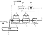
図1は、本発明を適用した混合ガスの成分測定装置の実施の形態例に係る構成図である。図1に示す成分測定装置1が本実施の形態例に係る装置であり、1種類以上の飽和炭化水素から成る炭化水素ガス(以下、炭化水素ガスと呼ぶ)に、異なる種類の他のガス(以下、混入ガスと呼ぶ)が混入した混合ガスを測定対象とし、層流流量計及び差圧式流量計でそれぞれ差圧を検出すると共に、密度計で密度を検出し、これら検出された値、上記炭化水素ガスがその成分比率によらず1種類のガスとして扱える性質、及び混合ガスの物性に係る関係式に基づいて、混入ガスの濃度と混合ガスの発熱量を求め、混合ガスの成分及び発熱量を簡易かつ高速に測定しようとするものである。
FIG. 1 is a configuration diagram according to an embodiment of a mixed gas component measuring apparatus to which the present invention is applied. A
図1に示す主配管2は、上記測定対象の混合ガスが流れる配管である。測定対象ガスは、上述の通り、メタン、エタン、プロパンなどの1種類以上の飽和炭化水素から成る炭化水素ガスと、窒素、空気、二酸化炭素などであってその成分が既知の混入ガスとの混合ガスである。 A main pipe 2 shown in FIG. 1 is a pipe through which the mixed gas to be measured flows. As described above, the measurement target gas is a mixture of a hydrocarbon gas composed of one or more kinds of saturated hydrocarbons such as methane, ethane, and propane, and a mixed gas whose components are known, such as nitrogen, air, and carbon dioxide. Gas.
サンプリング配管3は、上記主配管2から上記混合ガスを成分測定装置1に導く配管であり、図示していないが必要に応じてバルブ等の機器が取り付けられる。また、成分測定装置1での計測後、密度計13から排出されるガスは、適宜、大気放出等の方法で処分される。
The sampling pipe 3 is a pipe that guides the mixed gas from the main pipe 2 to the
成分測定装置1は、図1に示すように、層流流量計11、差圧式流量計12、密度計13、演算手段14、通信手段15等で構成される。層流流量計11、差圧式流量計12、及び、密度計13の間は配管で接続され、これらの計器は直列に配置される。なお、図1に示す本実施の形態例では、層流流量計11、差圧式流量計12、及び、密度計13の順で配列しているが、これは一例であって、他の配置とすることも可能である。但し、後述する本成分測定装置1の測定原理から、層流流量計11及び差圧式流量計12は、その順番に関わらず直列に配置する必要がある。すなわち、両流量計で同じ流量Qの混合ガスを測定対象とする必要がある。また、本実施の形態例では、測定対象ガスを主配管2から分岐して測定しているが、可能であれば、主配管2に成分測定装置1を設置しても良い。
As shown in FIG. 1, the
また、演算手段14と、層流流量計11、差圧式流量計12、密度計13、及び通信手段15とは通信線で接続され、各検出値、測定結果等が授受される。
The calculation means 14, the
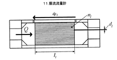
層流流量計11は、測定対象ガスの粘性(粘度μ(Pa・s))を用いる一般的な層流流量計である。図2は、層流流量計11の構造を示す図である。図2において左側から流入した流量Q(m3/s)の測定対象ガス(混合ガス)は、nl本の直径dl(m)、長さll(m)の細管を通過して右側へ流出する。そして、その際、細管の前後における差圧dpl(Pa)を差圧計により検出する。このとき、当該層流流量計11では、下記数1の関係式が成り立つ。
The

通常の使用の場合には、測定対象ガスの粘度μが既知であり、差圧dplを検出することによって、上記数1の式から流量Qを求めることができる。本成分測定装置1では、検出した差圧dplの値が演算手段14に送られる。
In the case of normal use, the viscosity of the measurement target gas μ is known, by detecting the differential pressure dp l, it can be determined the flow rate Q from the formula in
次に、差圧式流量計12は、測定対象ガスの密度ρ(kg/ m3)を用いる一般的な差圧式流量計である。図3は、差圧式流量計12の構造を示す図である。図3に示す流量計は一例としてベンチュリ流量計であり、左側から流入した流量Q(m3/s)の測定対象ガス(混合ガス)は、直径Dv(m)の通路、直径Dv(m)から直径dv(m)へ絞られる通路を通過して右側へ流出する。そして、その際、上記直径が絞られる通路の前後における差圧dpv(Pa)を差圧計により検出する。このとき、当該層流流量計12では、下記数2の関係式が成り立つ。
Next, the differential pressure
通常の使用の場合には、測定対象ガスの密度ρが既知であり、差圧dpvを検出することによって、上記数2の式から流量Qを求めることができる。本成分測定装置1では、検出した差圧dpvの値が演算手段14に送られる。
In the case of normal use, the density ρ of the gas to be measured is known, by detecting the differential pressure dp v, it can be determined the flow rate Q from the formula of Equation 2. In the
次に、密度計13は、ガス密度を測定する一般的な密度計であり、例えば、振動管式や超音波式のものを用いることができる。密度計13は、差圧式流量計12から流出した混合ガスについて密度ρを検出し、その値は演算手段14に送られる。なお、前述の通り、密度計13の配置は、図1の通りでなくてもよく、主配管2から流量計11、12とは異なるサンプリング配管で混合ガスを導いて測定するようにしても良い。
Next, the
演算手段14は、上記層流流量計11、差圧式流量計12、及び、密度計13での検出結果、及び、予め受信して保持する物性値等を用い、測定対象である混合ガスの発熱量と混入ガスの濃度を算出する部分である。当該算出に用いられる具体的な関係式、数値等については後述する。なお、本演算手段14は、ASIC等のハードウェアで構成しても良いし、プログラムとそのプログラムに従って処理を実行するCPU等で構成しても良い。
The calculation means 14 uses the detection results of the
通信手段15は、本成分測定装置1と外部との通信インターフェースであり、演算手段14での測定結果(演算結果)を所定の外部装置に送信する。また、演算手段14で必要な物性値等のデータを外部から受信して演算手段14へ送信する。なお、当該物性値等の受信は、本成分測定装置1に操作・入力手段を設け、この操作・入力手段から人手で値を入力することで行なわれても良い。
The
次に、このような構成を有する本成分測定装置1における測定手順と処理内容について説明する。まず、測定対象としている前述した混合ガスの扱い方について説明する。複数種類の飽和炭化水素が混合したガスの密度と粘度については特開平3−39623号公報に記載されているようにその混合したガスの発熱量H(J/m3)に対して、密度ρは比例、粘度μは反比例の関係があり、下記(a)式及び(b)式が成り立つ。
Next, the measurement procedure and processing contents in the
ρ=K2H (a)式
μ=K4/H (b)式
この2式から密度と粘度は下記(c)式の通り反比例の関係にあることがわかる。
ρ = K 2 H (a) Formula μ = K 4 / H (b) Formula From these two formulas, it can be seen that the density and the viscosity are in an inversely proportional relationship as shown in the following formula (c).
μ=K4K2/ρ (c)式
ここで密度ρは、下記(d)式の通りこの混合ガスの平均分子量maveに比例する。
μ = K 4 K 2 / ρ (c) Formula Here, the density ρ is proportional to the average molecular weight m ave of this mixed gas as represented by the following formula (d).
ρ=K7mave (d)式
なお、K2、K4、K7は、それぞれ、所定の定数である。
ρ = K 7 m ave (d) Formula K 2 , K 4 , and K 7 are respectively predetermined constants.
以上のことから、複数の飽和炭化水素が混合したガスについては、そのガスを構成する飽和炭化水素の成分割合に関わらず、混合したガスの密度(平均分子量)が同じガスについてはその粘度も同じになることがわかる。これは飽和炭化水素が混合したガスについては、そのガスを構成する飽和炭化水素の成分割合に関わらず、平均分子量(又は密度又は粘度)が同じであれば単一のガスと見なせることを示している。 From the above, for a gas in which a plurality of saturated hydrocarbons are mixed, the viscosity is the same for a gas having the same density (average molecular weight) regardless of the component ratio of the saturated hydrocarbon constituting the gas. It turns out that it becomes. This indicates that a gas mixed with saturated hydrocarbons can be regarded as a single gas if the average molecular weight (or density or viscosity) is the same, regardless of the component ratio of the saturated hydrocarbons constituting the gas. Yes.
従って、飽和炭化水素が混合したガスに異なる種類の他のガス、すなわち、上記混入ガスが混入した、測定対象である混合ガスは2種類のガスの混合ガスとして取り扱うことが可能である。よって、本成分測定装置1では、測定対象の混合ガスが、上記炭化水素ガスと上記混入ガスの2種類のガスの混合物であるとして取扱い、その混合比率(成分分率)を、それぞれ、x1及びx2とする。
Therefore, another type of gas mixed with saturated hydrocarbons, that is, a mixed gas as a measurement target in which the mixed gas is mixed can be handled as a mixed gas of two types of gases. Therefore, in this
図4は、本成分測定装置1における測定・処理手順を例示したフローチャートである。測定時には、前述したサンプリング配管3から混合ガスが導かれ、まず、層流流量計11における測定が行われる(ステップS1)。ここでは、上記導かれた混合ガスが流量計内を通過する際の、前述した差圧dplを検出し、その値を演算手段14に送る。
FIG. 4 is a flowchart illustrating a measurement / processing procedure in the
次に、層流流量計11を通過した混合ガスは、差圧式流量計12に導かれて測定が行われる(ステップS2)。ここでも、上記導かれた混合ガスが流量計内を通過する際の、前述した差圧dpvを検出し、その値を演算手段14に送る。
Next, the mixed gas that has passed through the
その後、差圧式流量計12を通過した混合ガスは密度計13に導かれ、ここで密度が検出される(ステップS3)。検出された密度は演算手段14に送られる。
Thereafter, the mixed gas that has passed through the differential pressure
以上、測定対象ガスについての測定が終了すると、演算手段14は、上記流量計11、12、及び密度計13から送信された検出値、予め保持する各種既知値、及び混合ガスの挙動や物性に係る各種関係式に基づいて、混入ガスの濃度と混合ガスの発熱量を求めるために必要な各未知値を算出する(ステップS4)。
As described above, when the measurement of the measurement target gas is completed, the calculation means 14 determines the detected values transmitted from the
以下に、当該算出に用いられる上記関係式について説明する。 Hereinafter, the relational expression used for the calculation will be described.
まず、前記層流流量計11で検出された差圧dplと混合ガスの流量Qと混合ガスの粘度μには、前述した数1の関係が成り立つので当該関係式が用いられる。当該式において、流量Qと粘度μは未知数であり、他の値は既知である。すなわち、差圧dplは前述の通り測定され、その他の既知値は、流量計の仕様として予め演算手段14に保持される。
First, the laminar flow the viscosity of the flow rate Q and the mixed
また、前記差圧式流量計12で検出された差圧dpvと混合ガスの流量Qと混合ガスの密度ρには、前述した数2の関係が成り立つので当該関係式が用いられる。当該式において、流量Qは未知数であり、他の値は既知である。すなわち、差圧dpvと密度ρは前述の通り測定され、その他の既知値は、流量計の仕様として予め演算手段14に保持される。
Also, the difference in pressure flow density of
また、混合ガスの密度と各成分ガスの密度、すなわち、炭化水素ガスの密度ρ1と混入ガスの密度ρ2、との間には、下記数3に示す関係式が成り立ち、当該式が用いられる。 Further, the following relational expression 3 is established between the density of the mixed gas and the density of each component gas, that is, the density ρ 1 of the hydrocarbon gas and the density ρ 2 of the mixed gas, and this formula is used. It is done.
![]()
![]()
ここで、炭化水素ガスの密度ρ1と各ガスの成分分率x1及びx2が未知数であり、上記測定されたρと混入ガスの密度ρ2は既知である。混入ガスは前述の通り、成分及びその成分割合が既知であるため、密度ρ2も既知であり、予め演算手段14に保持される。 Here, the density ρ 1 of the hydrocarbon gas and the component fractions x 1 and x 2 of each gas are unknown, and the measured ρ and the density ρ 2 of the mixed gas are known. As described above, since the component and the component ratio of the mixed gas are known, the density ρ 2 is also known and is held in the computing means 14 in advance.
また、上述した(d)式から、炭化水素ガスについては下記数4に示す関係式が成り立ち、当該式が用いられる。 Further, from the above-described equation (d), the following relational expression is established for the hydrocarbon gas, and this equation is used.
![]()
![]()
ここで、炭化水素ガスの密度ρ1と炭化水素ガスの分子量m1が未知数であり、係数K7は、既知値として予め演算手段14に保持される。 Here, the density ρ 1 of the hydrocarbon gas and the molecular weight m 1 of the hydrocarbon gas are unknown numbers, and the coefficient K 7 is held in advance in the computing means 14 as a known value.
また、混合ガスの粘度μと各成分ガスの粘度、すなわち、炭化水素ガスの粘度μ1と混入ガスの粘度μ2、との間には、下記数5に示す関係式が成り立ち、当該式が用いられる。 Further, the relational expression shown in the following equation 5 holds between the viscosity μ of the mixed gas and the viscosity of each component gas, that is, the viscosity μ 1 of the hydrocarbon gas and the viscosity μ 2 of the mixed gas. Used.
なお、上記数5に示す1番目の式は、Sutherlandの式であり、2番目及び3番目の式は、Wilkeの式である。ここで、混合ガス及び炭化水素ガスの粘度μ及びμ1、成分分率x1及びx2、炭化水素ガスの密度ρ1及び分子量m1が未知数であり、混入ガスの粘度μ2、密度ρ2、分子量m2が既知である。既知値は予め演算手段14に保持される。 Note that the first equation shown in Equation 5 is a Superland equation, and the second and third equations are Wilke's equations. Here, the viscosity μ and μ 1 of the mixed gas and the hydrocarbon gas, the component fraction x 1 and x 2 , the density ρ 1 of the hydrocarbon gas and the molecular weight m 1 are unknown, and the viscosity μ 2 and density ρ of the mixed gas are unknown. 2 and molecular weight m 2 are known. The known value is held in advance in the calculation means 14.
また、未知数である成分分率x1及びx2については、下記数6の関係式が成り立ち、当該式も用いられる。 Further, for the component fractions x 1 and x 2 which are unknown numbers, the following relational expression 6 is established, and this expression is also used.
また、上述した(c)式から、炭化水素ガスについては下記数7に示す関係式が成り立ち、当該式が用いられる。 Further, from the above-described equation (c), the following relational expression is established for the hydrocarbon gas, and this equation is used.
ここで、炭化水素ガスの密度ρ1と炭化水素ガスの粘度μ1が未知数であり、係数K2及びK4は、既知値として予め演算手段14に保持される。 Here, the density ρ 1 of the hydrocarbon gas and the viscosity μ 1 of the hydrocarbon gas are unknown numbers, and the coefficients K 2 and K 4 are held in the calculation means 14 in advance as known values.
以上説明した7つの式(数1〜数7に記載の式)を連立させて解くことにより、7つの未知数である、流量Q、密度ρ1、粘度μ及びμ1、混合比率x1及びx2、分子量m1の値を求めることが可能であり、演算手段14は、上記7つの式と上記各既知値によって、これらの値を算出する。
By solving the seven equations described above (equations described in
なお、上記の演算で用いられる、予め演算手段14に保持される既知値のうち、本成分測定装置1の設置後に変更が必要なものについては、通信手段15を介して適宜受信して保持する。また、前述のように、操作・入力手段を設けてここから人手で値を入力することで保持してもよい。
Of the known values used in the above calculation and previously stored in the calculation means 14, those that need to be changed after the installation of the
このようにして上記各値を算出すると、演算手段14は、混入ガスの混合比率x2が算出されているのでそれを混入ガスの濃度とし、また、炭化水素ガスの密度ρ1が算出されるので上記(a)式を用いて炭化水素ガスの発熱量H、すなわち、混合ガスの発熱量を算出する(ステップS5)。 When the above values are calculated in this way, the calculation means 14 calculates the mixed gas mixing ratio x 2 and uses it as the mixed gas concentration, and calculates the density ρ 1 of the hydrocarbon gas. Therefore, the calorific value H of the hydrocarbon gas, that is, the calorific value of the mixed gas is calculated using the above equation (a) (step S5).
当該求められた混入ガスの濃度と混合ガスの発熱量は、通信手段15から外部の所定箇所に送信され、出力される(ステップS6)。 The determined concentration of the mixed gas and the calorific value of the mixed gas are transmitted from the communication means 15 to a predetermined external location and output (step S6).
以上説明したように、本実施の形態例に係る成分測定装置1では、1種類以上の飽和炭化水素から成る炭化水素ガスと混入ガスの混合ガスについて、層流流量計11、差圧式流量計12、及び密度計13での測定結果、炭化水素ガスがその成分比率によらず1種類のガスとして扱える性質、及び混合ガスの物性に係る各関係式に基づいて、その発熱量と混入ガスの濃度を求める。従って、ガス濃度計などのセンサを必要とせず、また、測定後の校正も要しないので、適確な混入ガスの監視を安価な装置で容易に行うことができるようになる。
As described above, in the
また、層流流量計11、差圧式流量計12、及び密度計13を用いることで、高速(数10Hz)な測定が可能であり、混合ガスの発熱量及び混入ガスの濃度の変化を適切に捉えることが可能になる。
In addition, by using the
なお、上述の成分測定装置1では、通信手段15を有し、測定結果を外部へ送信していたが、成分測定装置1に表示装置などの出力手段を設け、測定した発熱量と混入ガス濃度を成分測定装置1側で出力するようにしても良い。
The above-described
本発明の保護範囲は、上記の実施の形態に限定されず、特許請求の範囲に記載された発明とその均等物に及ぶものである。 The protection scope of the present invention is not limited to the above-described embodiment, but covers the invention described in the claims and equivalents thereof.
1 成分測定装置、 2 主配管、 3 サンプリング配管、 11 層流流量計、 12 差圧式流量計、 13 密度計、 14 演算手段、 15 通信手段 1 component measuring device, 2 main piping, 3 sampling piping, 11 laminar flow meter, 12 differential pressure flow meter, 13 density meter, 14 computing means, 15 communication means
Claims (3)
流通するガスの差圧を検出し、当該差圧と前記ガスの粘度と前記ガスの流量との関係式に基づいて前記ガスの流量を求める流量計であって、前記混合ガスを流通させて差圧を検出する第一の流量計と、
流通するガスの差圧を検出し、当該差圧と前記ガスの密度と前記ガスの流量との関係式に基づいて前記ガスの流量を求める流量計であって、前記第一の流量計から流出した前記混合ガスが当該流量計に流入するように、あるいは、当該流量計から流出した前記混合ガスが前記第一の流量計に流入するように配置され、前記混合ガスを流通させて差圧を検出する第二の流量計と、
前記混合ガスの密度を検出する密度計と、
前記第一の流量計及び前記第二の流量計で検出された差圧、前記密度計で検出された密度、前記第一の流量計及び前記第二の流量計における前記関係式、前記第一のガスを1種類のガスとして扱える性質、及び、前記混合ガスの粘度と前記第一のガス及び前記第二のガスの粘度との関係式に基づいて、前記第一のガス及び前記第二のガスの混合比率を求める演算手段とを有する
ことを特徴とする混合ガスの成分測定装置。 A component measuring device for a mixed gas in which a first gas having an unknown density composed of one or more kinds of saturated hydrocarbons and a second gas having a known component different in type from the first gas are mixed,
A flowmeter that detects a differential pressure of a flowing gas and obtains a flow rate of the gas based on a relational expression between the differential pressure, the viscosity of the gas, and the flow rate of the gas, wherein the difference is obtained by circulating the mixed gas. A first flow meter for detecting pressure;
A flow meter that detects a differential pressure of a flowing gas and obtains a flow rate of the gas based on a relational expression between the differential pressure, the density of the gas, and the flow rate of the gas, The mixed gas flows into the flow meter, or the mixed gas flowing out of the flow meter flows into the first flow meter, and the mixed gas is circulated to reduce the differential pressure. A second flow meter to detect;
A density meter for detecting the density of the mixed gas;
Differential pressure detected by the first flow meter and the second flow meter, density detected by the density meter, the relational expression in the first flow meter and the second flow meter, the first Based on the property that the gas can be treated as one kind of gas, and the relational expression between the viscosity of the mixed gas and the viscosity of the first gas and the second gas, the first gas and the second gas An apparatus for measuring a component of a mixed gas, comprising: an arithmetic means for obtaining a mixing ratio of the gas.
前記演算手段は、更に、前記第一のガスの密度と発熱量が比例関係にあることを用いて、前記混合ガスの発熱量を求める
ことを特徴とする混合ガスの成分測定装置。 In claim 1,
The calculation unit further determines the calorific value of the mixed gas by using the fact that the density of the first gas and the calorific value are in a proportional relationship.
流通するガスの差圧を検出し、当該差圧と前記ガスの粘度と前記ガスの流量との関係式に基づいて前記ガスの流量を求める第一の流量計に、前記混合ガスを流通させて差圧を検出する工程と、
流通するガスの差圧を検出し、当該差圧と前記ガスの密度と前記ガスの流量との関係式に基づいて前記ガスの流量を求める流量計であって、前記第一の流量計から流出した前記混合ガスが当該流量計に流入するように、あるいは、当該流量計から流出した前記混合ガスが前記第一の流量計に流入するように配置される第二の流量計に、前記混合ガスを流通させて差圧を検出する工程と、
密度計で前記混合ガスの密度を検出する工程と、
前記第一の流量計及び前記第二の流量計で検出された差圧、前記密度計で検出された密度、前記第一の流量計及び前記第二の流量計における前記関係式、前記第一のガスを1種類のガスとして扱える性質、及び、前記混合ガスの粘度と前記第一のガス及び前記第二のガスの粘度との関係式に基づいて、前記第一のガス及び前記第二のガスの混合比率を求める工程とを有する
ことを特徴とする混合ガスの成分測定方法。 A method for measuring a component of a mixed gas in which a first gas having an unknown density composed of one or more kinds of saturated hydrocarbons and a second gas having a known component different in type from the first gas are mixed,
The mixed gas is circulated through a first flowmeter that detects the differential pressure of the gas flowing and obtains the flow rate of the gas based on the relational expression between the differential pressure, the viscosity of the gas, and the flow rate of the gas. Detecting the differential pressure;
A flow meter that detects a differential pressure of a flowing gas and obtains a flow rate of the gas based on a relational expression between the differential pressure, the density of the gas, and the flow rate of the gas, and flows out of the first flow meter. The mixed gas is disposed in a second flow meter arranged so that the mixed gas flows into the flow meter or the mixed gas flowing out of the flow meter flows into the first flow meter. A process of detecting a differential pressure by circulating
Detecting the density of the mixed gas with a density meter;
Differential pressure detected by the first flow meter and the second flow meter, density detected by the density meter, the relational expression in the first flow meter and the second flow meter, the first Based on the property that the gas can be treated as one kind of gas, and the relational expression between the viscosity of the mixed gas and the viscosity of the first gas and the second gas, the first gas and the second gas And a step of obtaining a mixing ratio of the gas.
Priority Applications (1)
| Application Number | Priority Date | Filing Date | Title |
|---|---|---|---|
| JP2008166468A JP5001908B2 (en) | 2008-06-25 | 2008-06-25 | Mixed gas component measuring apparatus and component measuring method |
Applications Claiming Priority (1)
| Application Number | Priority Date | Filing Date | Title |
|---|---|---|---|
| JP2008166468A JP5001908B2 (en) | 2008-06-25 | 2008-06-25 | Mixed gas component measuring apparatus and component measuring method |
Publications (2)
| Publication Number | Publication Date |
|---|---|
| JP2010008165A JP2010008165A (en) | 2010-01-14 |
| JP5001908B2 true JP5001908B2 (en) | 2012-08-15 |
Family
ID=41588862
Family Applications (1)
| Application Number | Title | Priority Date | Filing Date |
|---|---|---|---|
| JP2008166468A Expired - Fee Related JP5001908B2 (en) | 2008-06-25 | 2008-06-25 | Mixed gas component measuring apparatus and component measuring method |
Country Status (1)
| Country | Link |
|---|---|
| JP (1) | JP5001908B2 (en) |
Families Citing this family (14)
| Publication number | Priority date | Publication date | Assignee | Title |
|---|---|---|---|---|
| JP5646856B2 (en) * | 2010-02-03 | 2014-12-24 | 理研計器株式会社 | Calorimeter and calorimeter measuring method |
| JP5696385B2 (en) * | 2010-07-13 | 2015-04-08 | 横河電機株式会社 | Calorific value calculation system for liquefied natural gas and calorific value calculation method for liquefied natural gas |
| KR101856956B1 (en) * | 2011-12-27 | 2018-05-15 | 재단법인 포항산업과학연구원 | Method for Measuring Concentration of Gas in Mixed Gases |
| JPWO2013111777A1 (en) * | 2012-01-23 | 2015-05-11 | Jx日鉱日石エネルギー株式会社 | FUEL SUPPLY SYSTEM, FUEL CELL SYSTEM, AND OPERATION METHOD THEREOF |
| US20140377678A1 (en) * | 2012-01-23 | 2014-12-25 | Jx Nippon Oil & Energy Corporation | Fuel supply system, fuel cell system, and method for running each |
| NL2013587B1 (en) * | 2014-10-07 | 2016-10-03 | Berkin Bv | Method for determining the fractions of a flowing gaseous medium, as well as a system therefor. |
| JP6305459B2 (en) * | 2016-04-21 | 2018-04-04 | 新コスモス電機株式会社 | Gas detection device and gas detection method |
| JP6305458B2 (en) * | 2016-04-21 | 2018-04-04 | 新コスモス電機株式会社 | Gas detection method and gas detection device |
| JP6600854B2 (en) * | 2016-08-24 | 2019-11-06 | 株式会社フジキン | Pressure-type flow rate control device, flow rate calculation method thereof, and flow rate control method |
| JP6378457B2 (en) * | 2018-03-06 | 2018-08-22 | 新コスモス電機株式会社 | Gas detection method and gas detection device |
| JP2018100980A (en) * | 2018-03-06 | 2018-06-28 | 新コスモス電機株式会社 | Gas detection method and gas detection device |
| CN110672172A (en) * | 2018-07-03 | 2020-01-10 | 辽宁思凯科技股份有限公司 | Internet of things MEMS (micro-electromechanical systems) thermal mass gas meter system device and gas flow measuring method |
| CA3051376C (en) | 2019-08-06 | 2020-04-28 | Surface Solutions Inc. | Methane monitoring and conversion apparatus and methods |
| JP6936378B1 (en) * | 2020-10-29 | 2021-09-15 | 横河電機株式会社 | Composition estimation device, composition estimation method, and composition estimation program |
Family Cites Families (4)
| Publication number | Priority date | Publication date | Assignee | Title |
|---|---|---|---|---|
| JPH0295248A (en) * | 1988-09-30 | 1990-04-06 | Oval Eng Co Ltd | Calorimeter |
| JPH06100510B2 (en) * | 1989-07-05 | 1994-12-12 | 東京瓦斯株式会社 | Calorimeter |
| JPH0743224A (en) * | 1993-07-28 | 1995-02-14 | Tokyo Gas Co Ltd | Calorimeter |
| JP2008116283A (en) * | 2006-11-02 | 2008-05-22 | Tokyo Meeta Kk | Flow meter |
-
2008
- 2008-06-25 JP JP2008166468A patent/JP5001908B2/en not_active Expired - Fee Related
Also Published As
| Publication number | Publication date |
|---|---|
| JP2010008165A (en) | 2010-01-14 |
Similar Documents
| Publication | Publication Date | Title |
|---|---|---|
| JP5001908B2 (en) | Mixed gas component measuring apparatus and component measuring method | |
| Talley et al. | Characterization of horizontal air–water two-phase flow in a round pipe part II: Measurement of local two-phase parameters in bubbly flow | |
| EP2893304B1 (en) | Ultrasonic flow metering using compensated computed temperature | |
| Jia et al. | Void fraction measurement of gas–liquid two-phase flow from differential pressure | |
| US6957586B2 (en) | System to measure density, specific gravity, and flow rate of fluids, meter, and related methods | |
| US9134155B2 (en) | Reynolds number based verification for ultrasonic flow metering systems | |
| CA2489944A1 (en) | Venturi augmented flow meter | |
| US11150121B2 (en) | Monitoring of fluid flow | |
| WO2008016697A2 (en) | Method for monitoring a flowing fluid | |
| US9702745B2 (en) | Characterizing multiphase fluid flow | |
| NO20101645L (en) | Multiphase flow paint method | |
| US9874480B2 (en) | Characterizing contents of conduits, in particular multiphase flow conduits | |
| GB2438081A (en) | Determining individual phase fractions for three phases within a fluid mixture | |
| US10288470B2 (en) | Method for operating a flowmeter and flowmeter | |
| JP3164632U (en) | Device for determining the flow rate of a bi-directional unsteady fluid flow | |
| EP4050307B1 (en) | Gas flow rate estimation method, hole diameter estimation method, gas flow rate estimation device, and hole diameter estimation device | |
| KR20130075675A (en) | Liquid sample vaporizing system, diagnosis system and diagnosis program | |
| JP2015222251A (en) | Inspection system | |
| GB2538803A (en) | A metering apparatus for and method of determining a characteristic of a fluid flowing through a pipe | |
| JP7037883B2 (en) | Exhaust flow rate measuring device, fuel consumption measuring device, program for exhaust gas flow rate measuring device, and exhaust gas flow rate measuring method | |
| JP6781158B2 (en) | Steam weight factor measuring instrument | |
| JP2006047071A (en) | Method and apparatus for measuring calorific value of liquefied natural gas | |
| Adefila et al. | Flow measurement of CO2 in a binary gaseous mixture using an averaging Pitot Tube and Coriolis mass flowmeters | |
| KR20220034328A (en) | Calorie measuring system of flare gas | |
| JP5843529B2 (en) | Calorie measurement method and system for liquefied natural gas |
Legal Events
| Date | Code | Title | Description |
|---|---|---|---|
| A621 | Written request for application examination |
Free format text: JAPANESE INTERMEDIATE CODE: A621 Effective date: 20100326 |
|
| A977 | Report on retrieval |
Free format text: JAPANESE INTERMEDIATE CODE: A971007 Effective date: 20120117 |
|
| A131 | Notification of reasons for refusal |
Free format text: JAPANESE INTERMEDIATE CODE: A131 Effective date: 20120221 |
|
| A521 | Written amendment |
Free format text: JAPANESE INTERMEDIATE CODE: A523 Effective date: 20120416 |
|
| TRDD | Decision of grant or rejection written | ||
| A01 | Written decision to grant a patent or to grant a registration (utility model) |
Free format text: JAPANESE INTERMEDIATE CODE: A01 Effective date: 20120515 |
|
| A01 | Written decision to grant a patent or to grant a registration (utility model) |
Free format text: JAPANESE INTERMEDIATE CODE: A01 |
|
| A61 | First payment of annual fees (during grant procedure) |
Free format text: JAPANESE INTERMEDIATE CODE: A61 Effective date: 20120518 |
|
| R150 | Certificate of patent or registration of utility model |
Ref document number: 5001908 Country of ref document: JP Free format text: JAPANESE INTERMEDIATE CODE: R150 Free format text: JAPANESE INTERMEDIATE CODE: R150 |
|
| FPAY | Renewal fee payment (event date is renewal date of database) |
Free format text: PAYMENT UNTIL: 20150525 Year of fee payment: 3 |
|
| R250 | Receipt of annual fees |
Free format text: JAPANESE INTERMEDIATE CODE: R250 |
|
| R250 | Receipt of annual fees |
Free format text: JAPANESE INTERMEDIATE CODE: R250 |
|
| R250 | Receipt of annual fees |
Free format text: JAPANESE INTERMEDIATE CODE: R250 |
|
| R250 | Receipt of annual fees |
Free format text: JAPANESE INTERMEDIATE CODE: R250 |
|
| LAPS | Cancellation because of no payment of annual fees |