JP5000886B2 - Arm head and head cover of wiper arm - Google Patents
Arm head and head cover of wiper arm Download PDFInfo
- Publication number
- JP5000886B2 JP5000886B2 JP2005351809A JP2005351809A JP5000886B2 JP 5000886 B2 JP5000886 B2 JP 5000886B2 JP 2005351809 A JP2005351809 A JP 2005351809A JP 2005351809 A JP2005351809 A JP 2005351809A JP 5000886 B2 JP5000886 B2 JP 5000886B2
- Authority
- JP
- Japan
- Prior art keywords
- arm
- head
- head cover
- main body
- arm head
- Prior art date
- Legal status (The legal status is an assumption and is not a legal conclusion. Google has not performed a legal analysis and makes no representation as to the accuracy of the status listed.)
- Active
Links
- 230000000694 effects Effects 0.000 description 2
- 239000011521 glass Substances 0.000 description 1
- 238000000034 method Methods 0.000 description 1
- 238000000465 moulding Methods 0.000 description 1
- 239000011347 resin Substances 0.000 description 1
- 229920005989 resin Polymers 0.000 description 1
Images


Classifications
-
- B—PERFORMING OPERATIONS; TRANSPORTING
- B60—VEHICLES IN GENERAL
- B60S—SERVICING, CLEANING, REPAIRING, SUPPORTING, LIFTING, OR MANOEUVRING OF VEHICLES, NOT OTHERWISE PROVIDED FOR
- B60S1/00—Cleaning of vehicles
- B60S1/02—Cleaning windscreens, windows or optical devices
- B60S1/04—Wipers or the like, e.g. scrapers
- B60S1/32—Wipers or the like, e.g. scrapers characterised by constructional features of wiper blade arms or blades
- B60S1/34—Wiper arms; Mountings therefor
- B60S1/3479—Means to cover the wiper parts
- B60S1/3481—Means to cover the wiper parts for mounting head
Landscapes
- Engineering & Computer Science (AREA)
- Mechanical Engineering (AREA)
Description
本発明は、ワイパー装置のワイパーアームに備えられるアームヘッド及びアームヘッド用のヘッドカバーに関する。 The present invention relates to an arm head provided in a wiper arm of a wiper device and a head cover for the arm head.
ワイパー装置は、一般に、ワイパーブレードと、ワイパーブレードを支持するワイパーアームと、ワイパーアームに連係される駆動機構とから構成される。ワイパーアームは、ワイパーブレードに連結される本体部分(アーム本体)と、駆動機構に連係する基端部分(アームヘッド)とから構成される。このようなアームヘッドとしては、アームヘッド本体とヘッドカバーとからなるものが知られている。 Generally, the wiper device includes a wiper blade, a wiper arm that supports the wiper blade, and a drive mechanism that is linked to the wiper arm. The wiper arm includes a main body portion (arm main body) connected to the wiper blade and a base end portion (arm head) linked to the drive mechanism. As such an arm head, one comprising an arm head main body and a head cover is known.
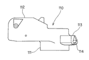
図13、図14には、従来のアームヘッドにおけるアームヘッド本体110とヘッドカバー120とを示す。図13に示すように、アームヘッド本体110は、駆動機構の連結軸が嵌合する円筒部111と、円筒部111から前方に延び出しアーム本体と連結される胴体部112と、円筒部111から後方に延び出した後端部113とを備えている。後端部113の両側には、ヘッドカバー120との連結用に、一対の軸穴114が形成されている。
13 and 14 show an arm head
図14に示すように、ヘッドカバー120は、アームヘッド本体110に被せられ得る椀形状の部材で、その後端付近の内面両側には、軸穴114に嵌合する一対の軸部121が形成されている。このような構成により、ヘッドカバー120は、アームヘッド本体110に対して、軸部121の回りで回動可能に軸支され、必要に応じて、アームヘッド本体110の上側に完全に被せられた状態と、アームヘッド本体110に対して略直立した状態(倒立状態)とをとり得るようになっている。
As shown in FIG. 14, the
ところで、ワイパーアームの組み立て作業においては、アームヘッド本体110に対してアーム本体を連結する等の作業が必要となるが、このような作業は、ヘッドカバー120をアームヘッド本体110に対して倒立状態にして行うのが効率的である。しかしながら、従来のヘッドカバー120は、安定的に倒立状態に保持されるような構成を有していなかったので、例えば作業者がヘッドカバー120に接触した場合等に、ヘッドカバー120がアームヘッド本体110側に倒れてしまったり、アームヘッド本体110から脱落してしまうことがあった。このため、作業効率が低下していた。
By the way, in the assembling work of the wiper arm, work such as connecting the arm main body to the arm head
本発明は、このような問題点に着目してなされたもので、ワイパーアーム本体に対してヘッドカバーを回動可能に取り付けたアームヘッドにおいて、ヘッドカバーをワイパーアーム本体に対して起立した状態(倒立状態)に安定的に保持できるものを提供することを目的とする。 The present invention has been made paying attention to such a problem, and in an arm head in which the head cover is rotatably attached to the wiper arm body, the head cover is raised with respect to the wiper arm body (inverted state). It is an object to provide a product that can be stably held.
本発明は、ワイパーアームのアームヘッド本体に取り付けられ得るアームヘッド用ヘッドカバーにおいて、前記アームヘッド本体の軸穴内に軸支されうる軸部と、前記ヘッドカバーが前記アームヘッド本体に対して起立する状態となったときに、前記アームヘッド本体の凹部に嵌合する突起部とを備え、前記突起部の凹部に対する嵌合により、前記ヘッドカバーがアームヘッド本体に対して起立した状態に保持されるようにした。 The present invention relates to an arm head head cover that can be attached to an arm head body of a wiper arm, a shaft portion that can be pivotally supported in a shaft hole of the arm head body, and a state in which the head cover stands with respect to the arm head body. And a projection that fits into the recess of the arm head body, and the head cover is held upright with respect to the arm head body by fitting the projection into the recess. .
前記突起部は、前記ヘッドカバーの下縁部両側に設けられていてもよい。
また、本発明は、アームヘッド本体と、前記アームヘッドに取り付けられ得るヘッドカバーとを備えたワイパーアーム用アームヘッドにおいて、前記アームヘッド本体に軸穴を備える一方、前記ヘッドカバーに軸部を備え、前記ヘッドカバーは、前記軸穴に前記軸部が軸支されることにより、前記アームヘッド本体に対して回動可能に取り付けられるようにするとともに、前記アームヘッド本体に凹部を備える一方、前記ヘッドカバーに突起部を備え、前記ヘッドカバーが前記アームヘッド本体に対して起立する状態となったときに、前記凹部に前記突起部が嵌合して、前記ヘッドカバーが起立状態に保持されるようにした。
The protrusions may be provided on both sides of the lower edge of the head cover.
Further, the present invention provides an arm head for a wiper arm comprising an arm head main body and a head cover that can be attached to the arm head, wherein the arm head main body includes a shaft hole, while the head cover includes a shaft portion, The head cover is rotatably attached to the arm head main body by pivotally supporting the shaft portion in the shaft hole, and has a recess in the arm head main body, while the head cover has a protrusion. When the head cover comes up with respect to the arm head main body, the projection is fitted into the recess so that the head cover is held in the upright state.
前記アームヘッド本体の凹部は、前記アームヘッド本体の底部に設けられ、前記ヘッドカバーの突起部は、前記ヘッドカバーの下縁部に設けられていてもよい。
前記アームヘッド本体の凹部は、前記アームヘッド本体の両側に設けられ、前記ヘッドカバーの突起部は、前記ヘッドカバーの両側に設けられ、前記アームヘッド本体の両側から前記凹部に嵌合するようにしてもよい。
The recess of the arm head main body may be provided at the bottom of the arm head main body, and the protrusion of the head cover may be provided at the lower edge of the head cover.
The recesses of the arm head main body are provided on both sides of the arm head main body, and the protrusions of the head cover are provided on both sides of the head cover so as to fit into the concave portions from both sides of the arm head main body. Good.
本発明によれば、ヘッドカバー(例えばヘッドカバー20)をアームヘッド本体(例えばアームヘッド本体10)に対して起立する状態(倒立状態)としたとき、ヘッドカバーの突起部(例えばストッパ突起26A、26B)がアームヘッド本体の凹部(例えば凹部16A、16B)に嵌合するようにしたので、アームヘッド本体に対するヘッドカバーの前後左右への動きは、この嵌合によって抑制される。したがって、ヘッドカバーはアームヘッド本体に対して起立した状態に保持され、ヘッドカバーがアームヘッド本体側に倒れてしまうことや、アームヘッド本体から脱落してしまうことが有効に防止されるので、ヘッドカバーを倒立状態として行われる作業(例えばワイパーアームの組み立て作業)に支障が生じないようにできる。
According to the present invention, when the head cover (for example, the head cover 20) is in a standing state (inverted state) with respect to the arm head body (for example, the arm head body 10), the protrusions (for example, the
以下、添付図面を参照しながら本発明の各実施形態を説明する。
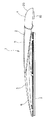
図1、図2には、ワイパーブレード組立体1の全体構成を示す。図示されるように、ワイパーブレード組立体1は、ワイパーアーム2とワイパーブレード3とから構成される。
Hereinafter, embodiments of the present invention will be described with reference to the accompanying drawings.
1 and 2 show the overall configuration of the wiper blade assembly 1. As shown in the figure, the wiper blade assembly 1 includes a
ワイパーアーム2は、アームヘッド4とアーム本体5とから構成される。アーム本体5は、基端部において、アームヘッド4に回動可能に連結されている。アームヘッド4は、図示されない駆動機構に連係される部分で、アームヘッド本体10とヘッドカバー20とから構成されている。アームヘッド本体10とヘッドカバー20の詳細な構成については後述する。
The
ワイパーブレード3は、支持部6とブレードラバー7とから構成される。支持部6は、複数のレバーから構成され、アーム本体5の先端部に回動可能に取り付けられるようになっている。ブレードラバー7は、支持部6に支持されている。
The
このような構成により、駆動機構がワイパーアーム2を駆動すると、ワイパーアーム2に支持されたワイパーブレード3のブレードラバー7が、自動車のガラス面等の被払拭面を払拭するようになっている。
With this configuration, when the drive mechanism drives the
図3から図5には、アームヘッド4のアームヘッド本体10を詳細に示す。なお、以下の記載においては、説明の便宜上、アームヘッド本体10のヘッドカバー20が被せられる側をアームヘッド本体10の上側とし、この上下方向を横切る方向をアームヘッド本体10の横方向とする。
3 to 5 show the
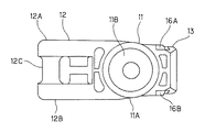
図示されるように、アームヘッド本体10は、例えば樹脂の一体成型で形成されるもので、駆動モータ側への連結部分である円筒部11と、この円筒部11から前方に延びる胴体部12と、円筒部11から後方に延びる後端部13とを備えている。円筒部11は、円筒形の側面11Aと天面11Bからなる部分で、円筒形側面11Aの内側に、駆動機構の連結軸(図示せず)が嵌合するようになっている。
As shown in the figure, the arm head
胴体部12は、アーム本体5との連結部分となるもので、両側側壁12A、12Bの間に、取り付け軸12Cを備えている。この取り付け軸12Cに、アーム本体5の基端が取り付けられる。また、側壁12A、12Bの外側面には、それぞれ、嵌合穴12D、12E(図には12Dのみ図示)と、これらの嵌合穴12D、12Eから胴体部12の上面付近に延びる凹部12F、12G(図には12Fのみ図示)が形成されている。ヘッドカバー20をアームヘッド本体10に被せたとき、アームヘッド本体10の突起部23A、23B(図8参照)は、凹部12F、12Gを通って嵌合穴12D、12E内に嵌合する。この嵌合により、ヘッドカバー20は、アームヘッド本体10に被せられた状態で保持されるようになっている。
The
後端部13は、円筒部11の略中段付近から後方に延び出している。後端部13は、ヘッドカバー20が軸支される部分であり、その後端付近の両側部に、円形の軸穴14A、14Bを備えている。これらの軸穴14A、14Bには、それぞれヘッドカバー20の軸部25A、25B(図6〜図8参照)が装着される。軸穴14A、14Bの側方には、横方向(アームヘッド本体10の長手方向)に延びる案内溝15A、15Bが形成され、後端部13の後端まで切り欠かれている。ヘッドカバー20の軸部25A、25Bは、この案内溝15A、15Bを通って、軸穴14A、14B内に装着される。なお、案内溝15A、15Bの幅は、軸部25A、25Bの軸回りで最小の厚みL1(図9参照)よりも僅かに広く、軸部25A、25Bを横方向から見たときの厚みL3(図9参照)よりも小さく形成されている。
The
延長部13の下面の略中央付近両側には、矩形の凹部16A、16Bが形成されている。詳しくは後述するように、凹部16A、16Bは、ヘッドカバー20をアームヘッド本体10に対して倒立状態(図11参照)としたときに、ヘッドカバー20のストッパ突起26A、26Bと嵌合して、ヘッドカバー20の倒立状態を保持するためのものである。
Rectangular recesses 16 </ b> A and 16 </ b> B are formed on both sides near the center of the lower surface of the
図6から図8には、ヘッドカバー20を詳細に示す。図示されるように、ヘッドカバー20は、両側の側面21A、21Bと、なだらかに湾曲した上面22とを備えた椀形状の部材であり、アームヘッド本体10の上側に装着され得る。アームヘッド本体10への装着時には、側面21A、21Bはアームヘッド本体10の両側を覆い、上面22はアームヘッド本体10の上部を覆うようになっている。
6 to 8 show the
ヘッドカバー20の側面21A、21Bの前端付近内側には、それぞれ、ヘッドカバー20の内側に延び出す円柱形の突起部23A、23Bが備えられる。前述したように、突起部23A、23Bは、は、アームヘッド本体20の嵌合穴12D、12Eに嵌合し、ヘッドカバー20をアームヘッド本体20に対して固定する。なお、ヘッドカバー20の上面22の前端側には、切り欠き部24(アーム本体5の基端部付近が配置される切り欠き)が形成されている。これにより、ヘッドカバー20をアームヘッド本体20に被せるとき、ヘッドカバー20の両側面21A、21Bの前端付近が外側に押し広げられて、突起部23A、23Bが嵌合穴12D、12Eに導かれ得るようになっている。
On the inner side near the front ends of the side surfaces 21A and 21B of the
ヘッドカバー20の側面21A、21Bの後端付近には、軸部25A、25Bが設けられ、ヘッドカバー20の内側に向けて延び出している。前述したように、軸部25A、25Bは、それぞれアームヘッド本体10の軸穴14A、14Bに回動可能に嵌入されるものである。
軸部25A、25Bは、半円形断面を有するもので、軸回りに異なる厚み(最小の厚みL1、最大の厚みL2、横方向から見た厚みL3等)を有している(図9参照)。この場合、軸部25A、25Bの半円形断面の直線部分が延びる方向Yは、ヘッドカバー20の横方向X(ヘッドカバー20がアームヘッド本体20に被せられたとき、アームヘッド本体20の横方向と一致する)に対して、角度θだけ傾いている。軸部25A、25Bを、このような形状としたことによる作用効果は、図10を用いて詳しく後述する。
The
ヘッドカバー20の側面21A、21Bの下縁の後端部には、ストッパ突起26A、26Bが備えられる。ストッパ突起26A、26Bは、前述したようにアームヘッド本体10の凹部16A、16Bに嵌合し得るもので、ヘッドカバー20の内側に向けて略垂直に延び出している。
次に、図10及び図11を用いて、本実施形態の作用について説明する。
図10には、ヘッドカバー20のアームヘッド本体10への組み付け時の様子を示す。図示されるように、組み付け作業においては、ヘッドカバー20を、アームヘッド本体10の後端側に角度θだけ傾けた状態、つまりヘッドカバー20の軸部25A、25Bの直線部分がアームヘッド本体10の横方向に沿って配置される状態に、配置する。これにより、ヘッドカバー20の軸部25A、25Bは、軸回りの最小の厚みL1を、アームヘッド本体10の案内溝15A、15Bに正対させて配置される。
Next, the effect | action of this embodiment is demonstrated using FIG.10 and FIG.11.
FIG. 10 shows a state when the
この状態から、ヘッドカバー20をアームヘッド本体10側に動かしていくことにより、ヘッドカバー20の軸部25A、25Bが、アームヘッド本体10の案内溝15A、15Bに挿入され、最終的に軸穴14A、14B内に達する。この場合、軸部25A、25Bの厚みL1は、案内溝15A、15Bの幅よりも小さいので、軸部25A、25Bは、圧入を必要とせずに、軸穴14A、14B内まで組み付けることができる。したがって、組み付け作業は、極めて容易である。
From this state, by moving the
軸部25A、25Bが軸穴14A、14B内に組み付けられたら、ヘッドカバー20をアームヘッド本体10に向けて(図10の反時計回りに)軸回りで回転させる。これにより、ヘッドカバー20の横方向とアームヘッド本体10の横方向が一致し、ヘッドカバー20がアームヘッド本体10の上側を完全に覆う状態とする。
When the
このように、ヘッドカバー20をアームヘッド本体10に対して完全に被せると、軸部25A、25Bの案内溝15A、15Bに正対する厚みL3(図9参照)は、案内溝15A、15Bの幅よりも大きくなる。したがって、軸部25A、25Bの案内溝15A、15Bを通った抜け出しは確実に防止される。
Thus, when the
また、アームヘッド本体10の案内溝15A、15Bは、ヘッドカバー20がアームヘッド本体10に対して配置される側(上側)と異なる側(横側)に向けて、軸穴14A、14Bから延びているので、ヘッドカバー20がアームヘッド本体10から、その配置される側(上側)に抜け出そうとしても、抜け出す方向には案内溝15A、15Bは存在しない。したがって、この点でも、軸部25A、25Bの軸穴14A、14Bからの抜け出しが防止されている。
The
図11には、アームヘッド本体20に組み付けられたヘッドカバー20を、アームヘッド本体20に対して起立させた状態(倒立状態)を示している。図示されるように、倒立状態において、ヘッドカバー20は、その横方向がアームヘッド本体10の横方向に対して略垂直を向くように配置されている。ヘッドカバー20を倒立状態とすることにより、例えば、ワイパーアーム2の組み立て工程において、アーム本体5のアームヘッド4への組み付け等の作業を容易に行うことができる。
FIG. 11 shows a state (inverted state) in which the
この倒立状態において、ヘッドカバー20のストッパ突起26A、26Bは、アームヘッド本体10の凹部16A、16B内に嵌合する。これにより、倒立状態のヘッドカバー20は、アームヘッド本体20に対して前後方向(図11の左右方向)及び左右方向(図11の紙面に垂直な方向)に確実に保持され、例えば組み立て作業中に作業者が誤ってヘッドカバー20に触れてしまった場合にも、ヘッドカバー20の倒立状態が保持され続けるようになっている。
In this inverted state, the stopper protrusions 26 </ b> A and 26 </ b> B of the
以上のように本実施形態によれば、ヘッドカバー20をアームヘッド本体10に対して倒立状態としたとき、ヘッドカバー20のストッパ突起26A、26Bがアームヘッド本体10凹部16A、16Bに嵌合するようにしたので、アームヘッド本体に対するヘッドカバーの前後左右への動きは、この嵌合によって抑制される。したがって、ヘッドカバー20はアームヘッド本体10に対して起立した状態に保持され、ヘッドカバー20がアームヘッド本体10側に倒れてしまうことや、アームヘッド本体10から脱落してしまうことが有効に防止されるので、ヘッドカバー10を倒立状態として行われる作業(例えばワイパーアーム2の組み立て作業)に支障が生じないようにできる。
As described above, according to the present embodiment, when the
1 ワイパーブレード組立体
2 ワイパーアーム
3 ワイパーブレード
4 アームヘッド
5 アーム本体
10 アームヘッド本体
11 胴体部
12 円筒部
13 後端部
14A、14B 軸穴
15A、15B 案内溝
16A、16B 凹部
20 ヘッドカバー
25A、25B 軸部
26A、26B ストッパ突起
DESCRIPTION OF SYMBOLS 1
Claims (2)
前記アームヘッド本体に軸穴を備える一方、前記ヘッドカバーに軸部を備え、前記ヘッドカバーは、前記軸穴に前記軸部が軸支されることにより、前記アームヘッド本体に対して回動可能に取り付けられるようにするとともに、
前記アームヘッド本体に凹部を備える一方、前記ヘッドカバーに突起部を備え、前記ヘッドカバーが前記アームヘッド本体に対して起立する状態となったときに、前記凹部に前記突起部が嵌合して、前記ヘッドカバーが起立状態に保持され、前記アームヘッド本体の凹部は、前記アームヘッド本体の底部に設けられ、前記ヘッドカバーの突起部は、前記ヘッドカバーの下縁の後端部に設けられ、ヘッドカバーの内側に向けて略垂直に延び出しているアームヘッド。 In an arm head for a wiper arm comprising an arm head body and a head cover that can be attached to the arm head,
The arm head body is provided with a shaft hole, while the head cover is provided with a shaft portion, and the head cover is pivotally attached to the arm head body by the shaft portion being pivotally supported by the shaft hole. As well as
While the arm head body is provided with a recess, the head cover is provided with a protrusion, and when the head cover is in a state of standing with respect to the arm head body, the protrusion is fitted into the recess, the head cover is held in the upright state, the recess of the arm head body is provided at the bottom of the arm head main body, the protrusion of the head cover is provided at the rear end of the lower edge of the head cover, the inside of the head cover Tei Rua Muheddo out extends substantially vertically toward.
前記アームヘッド本体の凹部は、前記アームヘッド本体の両側に設けられ、前記ヘッドカバーの突起部は、前記ヘッドカバーの両側に設けられ、前記アームヘッド本体の両側から前記凹部に嵌合するアームヘッド。 The arm head according to claim 1,
The recess of the arm head body is provided on both sides of the arm head main body, the protrusion of the head cover is provided on both sides of the head cover, luer Muheddo to adjust fit from both sides of the arm head main body in the recess.
Priority Applications (1)
| Application Number | Priority Date | Filing Date | Title |
|---|---|---|---|
| JP2005351809A JP5000886B2 (en) | 2005-12-06 | 2005-12-06 | Arm head and head cover of wiper arm |
Applications Claiming Priority (1)
| Application Number | Priority Date | Filing Date | Title |
|---|---|---|---|
| JP2005351809A JP5000886B2 (en) | 2005-12-06 | 2005-12-06 | Arm head and head cover of wiper arm |
Publications (2)
| Publication Number | Publication Date |
|---|---|
| JP2007153153A JP2007153153A (en) | 2007-06-21 |
| JP5000886B2 true JP5000886B2 (en) | 2012-08-15 |
Family
ID=38238049
Family Applications (1)
| Application Number | Title | Priority Date | Filing Date |
|---|---|---|---|
| JP2005351809A Active JP5000886B2 (en) | 2005-12-06 | 2005-12-06 | Arm head and head cover of wiper arm |
Country Status (1)
| Country | Link |
|---|---|
| JP (1) | JP5000886B2 (en) |
Families Citing this family (4)
| Publication number | Priority date | Publication date | Assignee | Title |
|---|---|---|---|---|
| US8205292B1 (en) | 2011-03-24 | 2012-06-26 | Trico Products Corporation | Wiper arm having swivel cover allowing access to the head and pivot shaft |
| US9260082B2 (en) | 2013-01-03 | 2016-02-16 | Trico Products Corporation | Wiper arm assembly having pivotal cover allowing access to pivot shaft |
| US9616854B2 (en) | 2013-04-25 | 2017-04-11 | Trico Products Corporation | Mounting assembly for wiper blade and wiper arm |
| CN216684383U (en) | 2020-11-26 | 2022-06-07 | 台州法雷奥温岭汽车零部件有限公司 | Windscreen wiper |
Family Cites Families (4)
| Publication number | Priority date | Publication date | Assignee | Title |
|---|---|---|---|---|
| JP3607154B2 (en) * | 2000-03-02 | 2005-01-05 | アスモ株式会社 | The head cover of the arm head that composes the wiper arm |
| JP2002002455A (en) * | 2000-04-18 | 2002-01-09 | Mitsuba Corp | Cover body for arm head in wiper device |
| JP4673970B2 (en) * | 2000-10-16 | 2011-04-20 | 日本ワイパブレード株式会社 | Mounting structure of head cover of vehicle wiper device |
| JP3869232B2 (en) * | 2001-04-20 | 2007-01-17 | アスモ株式会社 | Wiper arm |
-
2005
- 2005-12-06 JP JP2005351809A patent/JP5000886B2/en active Active
Also Published As
| Publication number | Publication date |
|---|---|
| JP2007153153A (en) | 2007-06-21 |
Similar Documents
| Publication | Publication Date | Title |
|---|---|---|
| US8671505B2 (en) | Windshield wiper blade assembly | |
| JP6006233B2 (en) | Wiper, wiper lever assembly and wiper blade | |
| JP5645284B1 (en) | Wiper arm | |
| JP5000886B2 (en) | Arm head and head cover of wiper arm | |
| JP4038798B2 (en) | Vehicle wiper | |
| JP2005022632A (en) | Wiper blade | |
| US8627539B2 (en) | Connector device for coupling wiper arm | |
| JP5000885B2 (en) | Arm head and head cover of wiper arm | |
| US20050217057A1 (en) | Wiper apparatus and wiper structure | |
| KR100935738B1 (en) | Exterior rear view mirror for vehicles | |
| JP5195447B2 (en) | Wiper blade | |
| JP2005297600A (en) | Wiper blade connection structure | |
| JP6012300B2 (en) | Mirror base structure | |
| JP2013075536A (en) | Vehicle side mirror | |
| EP3023300B1 (en) | Mirror device for vehicle | |
| JP4018072B2 (en) | Wiper structure | |
| JP2013043472A (en) | Mechanism for connecting wiper blade | |
| JP2009202730A (en) | Wiper arm | |
| JP4018073B2 (en) | Wiper device | |
| JP6605102B1 (en) | Wiper blade | |
| JP4866226B2 (en) | Spacer member | |
| JP2010168024A (en) | Wiper arm | |
| JP6310770B2 (en) | Vehicle side mirror | |
| JP5886562B2 (en) | Actuator, connector assembly and connector for electric mirror device | |
| CN214227993U (en) | Generator protective cover |
Legal Events
| Date | Code | Title | Description |
|---|---|---|---|
| A621 | Written request for application examination |
Free format text: JAPANESE INTERMEDIATE CODE: A621 Effective date: 20081205 |
|
| A977 | Report on retrieval |
Free format text: JAPANESE INTERMEDIATE CODE: A971007 Effective date: 20101224 |
|
| A131 | Notification of reasons for refusal |
Free format text: JAPANESE INTERMEDIATE CODE: A131 Effective date: 20110808 |
|
| RD04 | Notification of resignation of power of attorney |
Free format text: JAPANESE INTERMEDIATE CODE: A7424 Effective date: 20110906 |
|
| A521 | Request for written amendment filed |
Free format text: JAPANESE INTERMEDIATE CODE: A523 Effective date: 20111005 |
|
| TRDD | Decision of grant or rejection written | ||
| A01 | Written decision to grant a patent or to grant a registration (utility model) |
Free format text: JAPANESE INTERMEDIATE CODE: A01 Effective date: 20120418 |
|
| A01 | Written decision to grant a patent or to grant a registration (utility model) |
Free format text: JAPANESE INTERMEDIATE CODE: A01 |
|
| A61 | First payment of annual fees (during grant procedure) |
Free format text: JAPANESE INTERMEDIATE CODE: A61 Effective date: 20120517 |
|
| R150 | Certificate of patent or registration of utility model |
Ref document number: 5000886 Country of ref document: JP Free format text: JAPANESE INTERMEDIATE CODE: R150 Free format text: JAPANESE INTERMEDIATE CODE: R150 |
|
| FPAY | Renewal fee payment (event date is renewal date of database) |
Free format text: PAYMENT UNTIL: 20150525 Year of fee payment: 3 |
|
| R250 | Receipt of annual fees |
Free format text: JAPANESE INTERMEDIATE CODE: R250 |
|
| R250 | Receipt of annual fees |
Free format text: JAPANESE INTERMEDIATE CODE: R250 |
|
| R250 | Receipt of annual fees |
Free format text: JAPANESE INTERMEDIATE CODE: R250 |
|
| R250 | Receipt of annual fees |
Free format text: JAPANESE INTERMEDIATE CODE: R250 |
|
| R250 | Receipt of annual fees |
Free format text: JAPANESE INTERMEDIATE CODE: R250 |
|
| S531 | Written request for registration of change of domicile |
Free format text: JAPANESE INTERMEDIATE CODE: R313531 |
|
| S533 | Written request for registration of change of name |
Free format text: JAPANESE INTERMEDIATE CODE: R313533 |
|
| R350 | Written notification of registration of transfer |
Free format text: JAPANESE INTERMEDIATE CODE: R350 |
|
| R250 | Receipt of annual fees |
Free format text: JAPANESE INTERMEDIATE CODE: R250 |
|
| R250 | Receipt of annual fees |
Free format text: JAPANESE INTERMEDIATE CODE: R250 |
|
| R250 | Receipt of annual fees |
Free format text: JAPANESE INTERMEDIATE CODE: R250 |
|
| R250 | Receipt of annual fees |
Free format text: JAPANESE INTERMEDIATE CODE: R250 |
|
| R250 | Receipt of annual fees |
Free format text: JAPANESE INTERMEDIATE CODE: R250 |