JP5000505B2 - Progressive power lens - Google Patents
Progressive power lens Download PDFInfo
- Publication number
- JP5000505B2 JP5000505B2 JP2007525964A JP2007525964A JP5000505B2 JP 5000505 B2 JP5000505 B2 JP 5000505B2 JP 2007525964 A JP2007525964 A JP 2007525964A JP 2007525964 A JP2007525964 A JP 2007525964A JP 5000505 B2 JP5000505 B2 JP 5000505B2
- Authority
- JP
- Japan
- Prior art keywords
- lens
- power
- progressive
- reference point
- distance
- Prior art date
- Legal status (The legal status is an assumption and is not a legal conclusion. Google has not performed a legal analysis and makes no representation as to the accuracy of the status listed.)
- Active
Links
Images


Classifications
-
- G—PHYSICS
- G02—OPTICS
- G02C—SPECTACLES; SUNGLASSES OR GOGGLES INSOFAR AS THEY HAVE THE SAME FEATURES AS SPECTACLES; CONTACT LENSES
- G02C7/00—Optical parts
- G02C7/02—Lenses; Lens systems ; Methods of designing lenses
- G02C7/06—Lenses; Lens systems ; Methods of designing lenses bifocal; multifocal ; progressive
- G02C7/061—Spectacle lenses with progressively varying focal power
- G02C7/063—Shape of the progressive surface
- G02C7/065—Properties on the principal line
Description
本発明は、累進屈折力レンズに関し、特に眼の調節力の補助として使用する累進屈折力レンズに関する。 The present invention relates to a progressive-power lens, and more particularly to a progressive-power lens that is used as an aid to eye accommodation.
老視の矯正には、単焦点レンズやバイフォーカルレンズ、累進屈折力レンズなどが用いられている。累進屈折力レンズは、装用時においてレンズの上方に位置する比較的遠方視に適した遠用部領域(以下、「遠用部」ともいう)と、レンズの下方に位置して比較的近方視に適した近用部領域(以下、「近用部」ともいう)と、遠用部と近用部との間に位置して双方の面屈折力を連続的に接続する累進部領域(以下、「累進部」ともいう)とを備えている。
なお、本発明では、遠用部においてレンズの度数を測定する測定基準点を「遠用基準点」と呼び、近用部においてレンズの度数を測定する測定基準点を「近用基準点」と呼ぶ。また、遠用基準点及び近用基準点を通り且つ累進面の屈折面上を鼻側領域と耳側領域とに分割する直線または曲線を「主注視線」と呼ぶ。主注視線は、累進屈折力レンズの加入度等の仕様を表す基準線として用いられ、累進面(累進屈折面)の設計を行う上で重要な基準線として用いられる。
従来の累進屈折力レンズでは、予め累進屈折面が加工された半製品レンズ(以下、「セミフィニッシュレンズ」と呼ぶ)が使用されている。即ち、眼鏡装用者の球面度数や乱視度数に合わせて、セミフィニッシュレンズの処方面を球面形状またはトーリック面形状に加工して眼鏡レンズを作成する。
通常、セミフィニッシュレンズにおける累進屈折面の面形状は、共用する度数範囲の中のある特定の処方度数において最も好ましい光学性能が得られるような面形状として設定される。従って、この特定の度数をセミフィニッシュレンズの基準度数とすると、基準度数付近の処方度数におけるレンズの光学性能は良好であるが、処方度数が基準度数から外れるに従って光学性能の低下が避けらないという欠点があった。ところが、近年、非球面加工技術の発達により、レンズ面を非球面形状に、特に自由曲面のような複雑な非球面形状に短時間の内に自由に加工することが可能になった。
その結果、装用者の処方や使用条件等を考慮して、従来は球面形状あるいはトーリック面形状であった処方面を個別に非球面化した累進屈折力レンズが製品化され、累進屈折力レンズの光学性能は処方度数に依存することなく広い度数範囲に亘って大幅に改善されるようになった。なお、このような場合に処方面に用いられる非球面は、対称性を持たない自由曲面、例えば多項式非球面、双三次スプラインやB−スプライン等のスプライン面形状などが一般的である。
累進屈折面だけでなく処方面も非球面化した両面非球面型の累進屈折力レンズは、たとえば特開2004−341086号公報などに開示されている。
一般に、累進屈折力レンズでは、遠用基準点及び近用基準点のうちの少なくとも一方の測定基準点におけるレンズの度数を、レンズメーターと呼ばれる測定器によって測定している。従来の累進屈折力レンズでは、処方面の全体が球面形状あるいはトーリック面形状であるため、装用者の処方度数と、レンズメーターによって測定基準点で測定した球面度数及び乱視度数とは実質的に一致していた。
ところが、装用状態における光学性能を重視して処方面を非球面化した累進屈折力レンズでは、処方面が非球面化されているために測定基準点において面非点隔差が発生する。その結果、レンズメーターでの測定に際して、処方度数とは異なる球面度数及び乱視度数が表示される。しかも、処方面に付与される非球面量が大きくなるに従って、レンズメーターによって測定した球面度数及び乱視度数と装用者の処方度数との差が大きくなる傾向がある。
そのため、メーカーでは、装用状態での度数を測定する特殊なレンズメーターを導入したり、本来の処方度数とは別に、一般的なレンズメーターで測定した場合に得られる度数を測定理論度数として併記したりしている。処方度数と測定理論度数とを併記することは、「二重表記」と呼ばれている。実際に、一般の眼鏡店では、装用状態での度数が測定可能な特殊なレンズメーターを導入することは困難であるため、二重表記による測定方法が主流となっている。
ちなみに、処方面を非球面化した両面非球面型の累進屈折力レンズの場合、処方面が球面形状またはトーリック面形状である従来の累進屈折力レンズと比較して、レンズメーターによる測定位置合わせの精度に起因する測定誤差が大きい。さらに、二重表記で表示される処方度数と測定理論度数との差は必ずしも一定ではなく、球面度数や乱視度数、乱視軸や加入度等の処方の様々な条件によって異なる値になる。そのため、二重表記の累進屈折力レンズの度数を測定する場合には、メーカーにより表示された測定理論度数をレンズ毎に全て確認する必要が生じる。
つまり、二重表記の累進屈折力レンズの度数測定では、従来の累進屈折力レンズとは異なる複雑な手順が必要となるうえ、測定に不慣れな人間が測定する場合や大量のレンズを測定する場合には、正確な測定結果を得るために従来の累進屈折力レンズよりも時間および労力が必要になる。そのため、一部の眼鏡店やユーザーからは、光学性能だけを重視せずに、レンズの度数測定をより容易に行うことのできる両面非球面型の累進屈折力レンズに対する要望が出ている。
そこで、特開2004−341086号公報に開示された従来の両面非球面型の累進屈折力レンズでは、処方度数と測定度数とが異なるという問題を解決するために、処方面上の主注視線に沿った線状部分の一部に面非点隔差の発生しない領域を設けている。
具体的には、実際にレンズをフレーム形状に加工する際に不要部分として廃棄される主注視線を含む遠用部の一部の領域において、処方面の主注視線上を面非点隔差の生じない形状とし、その領域でレンズの度数を測定することによって、処方度数と同じ測定度数が得られるように構成している。ところが、本願発明者の研究によると、従来のように面屈折力分布で評価されていた累進屈折力レンズでは、主注視線の形状による評価は重要であったが、透過光線におけるレンズ全体の光学性能を重視して両面を非球面化した両面非球面型の累進屈折力レンズにおいては、主注視線の一部の線状部分の面形状を規定するだけでは不十分であることがわかった。
即ち、自由曲面を用いた累進面を有する累進屈折力レンズにおいて、レンズ全体に亘って光学性能の改善を行うためには、処方面に対しても高次多項式やスプラインといった対称性を持たない非球面形状が必要である。ところが、このような対称性を持たない非球面形状では面の自由度が高いため、主注視線上の面形状を規定するだけでは隣接する領域の面形状を特定することはできない。つまり、たとえ処方面の主注視線上を球面形状に設定しても、主注視線から少し離れた位置の非球面量が大きくなり、光学性能への寄与が大きく変動することが避けられない場合もある。従って、少なくともレンズの度数を測定する領域においては、面としての形状の制御が必須となるが、特開2004−341086号公報の従来技術では主注視線上以外の領域における面形状に関して明確に開示されていない。
また、本来のレンズの度数測定は、装用者の処方通りにレンズが正しく作成されているか否かを確認するために行うものである。従って、累進屈折力レンズに限らず一般の眼鏡レンズでは、レンズの幾何学中心の近傍、あるいはレンズを装用する上で最も重要な位置に、測定基準点が配置されている。つまり、特開2004−341086号公報に記載されているようにフレーム形状外の主子午線(主注視線)上を面非点隔差の生じない形状にすれば、装用時での光学性能への影響を小さく抑えつつ処方度数と同じ測定度数を得ることはできるが、特開2004−341086号公報の従来技術で得られる測定度数は、本来求められているレンズの度数測定の目的とは異なり適切であるとはいえない。For correcting presbyopia, single focus lenses, bifocal lenses, progressive power lenses, and the like are used. The progressive-power lens is located at the upper part of the lens when worn and is suitable for far-distance viewing (hereinafter also referred to as “distance part”), and is located at the lower part of the lens and relatively near. A near area suitable for vision (hereinafter also referred to as “near area”) and a progressive area that is located between the distance area and the near area and continuously connects both surface refractive powers ( (Hereinafter also referred to as “progressive portion”).
In the present invention, the measurement reference point for measuring the lens power in the distance portion is referred to as a “distance reference point”, and the measurement reference point for measuring the lens power in the near portion is referred to as a “near reference point”. Call. A straight line or curve that passes through the distance reference point and the near reference point and divides the refracting surface of the progressive surface into a nose side region and an ear side region is referred to as a “main gaze line”. The main gazing line is used as a reference line representing specifications such as the addition power of the progressive addition lens, and is used as an important reference line in designing a progressive surface (progressive refractive surface).
In the conventional progressive-power lens, a semi-finished lens (hereinafter referred to as “semi-finish lens”) whose progressive-refractive surface is processed in advance is used. That is, the spectacle lens is created by processing the prescription surface of the semi-finished lens into a spherical shape or a toric surface shape according to the spherical power or astigmatism power of the spectacle wearer.
Usually, the surface shape of the progressive addition surface in the semi-finished lens is set as a surface shape that provides the most preferable optical performance at a specific prescription power within a common power range. Therefore, if this specific power is the reference power of the semi-finished lens, the optical performance of the lens at the prescription power near the reference power is good, but the optical performance is inevitably lowered as the prescription power deviates from the reference power. There were drawbacks. However, in recent years, with the development of aspherical processing technology, it has become possible to freely process a lens surface into an aspherical shape, particularly into a complex aspherical shape such as a free-form surface within a short time.
As a result, taking into account the wearer's prescription and usage conditions, a progressive power lens with aspherical prescription surfaces that were conventionally spherical or toric surfaces was commercialized. Optical performance has been greatly improved over a wide power range without depending on the prescription power. In this case, the aspheric surface used for the prescription surface is generally a free-form surface having no symmetry, for example, a polynomial aspheric surface, a spline surface shape such as a bicubic spline or a B-spline.
A double-sided aspherical progressive-power lens in which not only the progressive-refractive surface but also the prescription surface is aspherical is disclosed in, for example, Japanese Patent Application Laid-Open No. 2004-341086.
In general, in a progressive-power lens, the power of a lens at at least one of a distance reference point and a near reference point is measured by a measuring instrument called a lens meter. In conventional progressive power lenses, the prescription surface is entirely spherical or toric, so the prescription power of the wearer is substantially equal to the spherical power and astigmatism power measured at the measurement reference point by the lens meter. I did it.
However, in a progressive-power lens in which the prescription surface is aspherical in consideration of the optical performance in the wearing state, the prescription surface is aspherical, so that a surface astigmatism occurs at the measurement reference point. As a result, a spherical power and an astigmatism power different from the prescription power are displayed when measuring with a lens meter. Moreover, as the amount of aspherical surface imparted to the prescription surface increases, the difference between the spherical power and astigmatism power measured by the lens meter and the prescription power of the wearer tends to increase.
For this reason, manufacturers introduce a special lens meter that measures the power in the wearing state, or separate the frequency obtained by measuring with a general lens meter separately from the original prescription power as the measurement theoretical power. It is. Writing the prescription frequency and the measurement theory frequency together is called “double notation”. Actually, in general spectacle stores, it is difficult to introduce a special lens meter capable of measuring the power in a worn state, so the measurement method by double notation is mainstream.
By the way, in the case of a double-sided aspherical progressive-power lens with an aspheric prescription surface, compared to a conventional progressive-power lens with a spherical or toric surface prescription surface, the measurement alignment by the lens meter Measurement error due to accuracy is large. Further, the difference between the prescription power displayed in double notation and the measurement theoretical power is not necessarily constant, and varies depending on various prescription conditions such as spherical power, astigmatism power, astigmatic axis, and addition power. For this reason, when measuring the power of the progressive power lens of double notation, it is necessary to check all the measurement theoretical powers displayed by the manufacturer for each lens.
In other words, the power measurement of a progressive power lens with a double notation requires a complicated procedure different from that of a conventional progressive power lens, and when a person who is unfamiliar with the measurement measures a large number of lenses. Requires more time and effort than conventional progressive power lenses to obtain accurate measurement results. For this reason, some spectacle stores and users demand a progressive-power lens having a double-sided aspheric surface that makes it possible to more easily measure the power of the lens without considering only the optical performance.
Therefore, in the conventional double-sided aspherical progressive-power lens disclosed in Japanese Patent Application Laid-Open No. 2004-341086, in order to solve the problem that the prescription power and the measurement power are different, the main gaze on the prescription surface is set. A region where no surface astigmatism is generated is provided in a part of the linear portion along the line.
Specifically, in some areas of the distance portion including the main gaze that is discarded as an unnecessary part when the lens is actually processed into a frame shape, an astigmatic difference occurs on the main gaze on the prescription surface. By measuring the lens power in that region, the same power as the prescription power can be obtained. However, according to the research of the present inventor, in the progressive power lens that has been evaluated by the surface power distribution as in the past, the evaluation by the shape of the main gazing line was important, but the entire lens in the transmitted light In a double-sided aspherical progressive-power lens in which both surfaces are aspherical with emphasis on performance, it has been found that it is not sufficient to define the surface shape of a part of the main gaze line.
That is, in a progressive-power lens having a progressive surface using a free-form surface, in order to improve the optical performance over the entire lens, the prescription surface does not have a symmetry such as a high-order polynomial or a spline. A spherical shape is required. However, since the degree of freedom of the surface is high in such an aspherical shape that does not have symmetry, the surface shape of the adjacent region cannot be specified only by defining the surface shape on the main gazing line. In other words, even if the prescription surface on the main line of sight is set to a spherical shape, the amount of aspherical surface at a position slightly away from the main line of sight increases, and the contribution to the optical performance may inevitably fluctuate. is there. Therefore, at least in the region where the power of the lens is measured, it is essential to control the shape as a surface. However, in the prior art disclosed in Japanese Patent Application Laid-Open No. 2004-34086, the surface shape in a region other than the main line of sight is clearly disclosed. Not.
Further, the power measurement of the original lens is performed in order to confirm whether or not the lens is correctly created in accordance with the wearer's prescription. Therefore, in general spectacle lenses as well as progressive-power lenses, measurement reference points are arranged in the vicinity of the geometric center of the lens or at the most important position for wearing the lens. That is, if the shape on the main meridian (main line of sight) outside the frame shape does not cause surface astigmatism as described in Japanese Patent Application Laid-Open No. 2004-341086, it affects the optical performance during wearing. Although it is possible to obtain the same measurement power as the prescription power while keeping the value low, the measurement power obtained by the conventional technique of Japanese Patent Application Laid-Open No. 2004-341086 is appropriate unlike the purpose of lens power measurement that is originally required. There is no such thing.
本発明は、前述の課題に鑑みてなされたものであり、装用状態における光学性能を良好に改善しているにもかかわらず、眼鏡店やユーザーによるレンズの度数測定を容易に行うことのできる累進屈折力レンズを提供することを目的とする。
前記課題を解決するために、本発明では、装用状態においてレンズの屈折面を鼻側領域と耳側領域とに分割する主注視線に沿って、比較的遠方視に適した遠用部領域と、該遠用部領域に対して比較的近方視に適した近用部領域と、前記遠用部領域と前記近用部領域との間において前記遠用部領域の面屈折力と前記近用部領域の面屈折力とを連続的に接続する累進部領域とを備えた累進屈折力レンズにおいて、
レンズの透過光線における光学性能を補正するために形成された処方面は非球面形状を有し、眼鏡フレーム内に設定された、前記遠用部領域の測定基準点である遠用基準点と前記近用部領域の測定基準である近用基準点の少なくとも一方の前記測定基準点において、前記処方面により発生する面非点隔差成分と処方度数の矯正に必要な球面またはトーリック面により発生する面非点隔差成分との差の絶対値の平均値が、レンズの度数を測定するための測定基準点を含む近傍の所定領域に亘って所定の値以下であることを特徴とする累進屈折力レンズを提供する。
本発明では、レンズの透過光線における光学性能を補正するために形成された処方面が非球面形状を有する。そして、処方面の非球面形状により発生する面非点隔差成分と処方度数の矯正に必要な球面またはトーリック面により発生する面非点隔差成分との差の絶対値の平均値(以下、単に「処方面の非球面化により実質的に発生する面非点隔差成分の平均値」あるいは「面非点隔差成分の平均値」という)が、レンズの度数を測定するための測定基準点を含む近傍の所定領域に亘って所定の値以下に抑えられている。
したがって、処方面の非球面化により装用状態における光学性能を補正する構成を採用しているにもかかわらず、例えばレンズメーターを用いて測定基準点を基準として測定することにより処方度数とほぼ同じ測定度数を得ることができる。すなわち、本発明の累進屈折力レンズでは、装用者の処方や使用条件等を考慮して装用状態における光学性能を良好に改善しているにもかかわらず、眼鏡店やユーザーによるレンズの度数測定を容易に行うことができる。
The present invention has been made in view of the above-described problems, and is a progressive that can easily measure the power of a lens by a spectacle store or a user even though the optical performance in a worn state is improved satisfactorily. An object is to provide a refractive lens.
In order to solve the above problems, in the present invention, a distance area that is relatively suitable for far vision along a main gaze line that divides the refractive surface of the lens into a nose area and an ear area in the wearing state. , A near vision area relatively suitable for near vision with respect to the distance vision area, and a surface refractive power of the distance vision area and the near distance between the distance vision area and the near vision area. In a progressive-power lens having a progressive area that continuously connects the surface refractive power of the application area,
The prescription surface formed to correct the optical performance in the transmitted light of the lens has an aspherical shape, and is set in the spectacle frame, the distance reference point that is the measurement reference point of the distance portion region, and the A surface generated by a spherical surface or a toric surface necessary for correcting the surface astigmatism component generated by the prescription surface and the prescription power at the measurement reference point of at least one of the near reference points that are the measurement reference of the near portion area. A progressive power lens characterized in that the average absolute value of the difference from the astigmatic difference component is not more than a predetermined value over a predetermined area in the vicinity including a measurement reference point for measuring the lens power I will provide a.
In this invention, the prescription surface formed in order to correct | amend the optical performance in the transmitted light of a lens has aspherical shape. And the average value of the absolute value of the difference between the surface astigmatism component generated by the aspheric shape of the prescription surface and the surface astigmatism component generated by the spherical surface or toric surface necessary for correcting the prescription power (hereinafter simply referred to as “ The average value of the surface astigmatism component that is substantially generated by the aspherical prescription surface or the "average value of the surface astigmatism component") includes the measurement reference point for measuring the lens power. Over a predetermined region, the value is suppressed to a predetermined value or less.
Therefore, in spite of adopting a configuration that corrects the optical performance in the wearing state by making the prescription surface aspherical, for example, the measurement is almost the same as the prescription frequency by measuring with a measurement reference point using a lens meter as a reference. You can get the frequency. That is, in the progressive-power lens of the present invention, although the optical performance in the wearing state is satisfactorily improved in consideration of the wearer's prescription and use conditions, the lens power measurement by the spectacle store or the user is performed. It can be done easily.
図1は、本発明の実施形態にかかる累進屈折力レンズの構成を概略的に示す図である。
図2は、第1実施例の比較例にかかる従来の累進屈折力レンズの透過光線での非点収差分布を示す図である。
図3は、第1実施例にかかる累進屈折力レンズの透過光線での非点収差分布を示す図である。
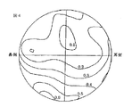
図4は、第1実施例にかかる累進屈折力レンズの処方面の非球面化により実質的に発生する面非点隔差成分の分布を示す図である。
図5は、第2実施例の比較例にかかる従来の累進屈折力レンズの透過光線での非点収差分布を示す図である。
図6は、第2実施例にかかる累進屈折力レンズの透過光線での非点収差分布を示す図である。
図7は、第2実施例にかかる累進屈折力レンズの処方面の非球面化により実質的に発生する面非点隔差成分の分布を示す図である。FIG. 1 is a diagram schematically showing a configuration of a progressive-power lens according to an embodiment of the present invention.
FIG. 2 is a diagram showing the astigmatism distribution in the transmitted light of the conventional progressive-power lens according to the comparative example of the first embodiment.
FIG. 3 is a diagram showing an astigmatism distribution in the transmitted light of the progressive addition lens according to the first example.
FIG. 4 is a diagram showing a distribution of surface astigmatism components substantially generated by making the prescription surface of the progressive-power lens according to the first example aspherical.
FIG. 5 is a diagram showing the astigmatism distribution in the transmitted light of the conventional progressive-power lens according to the comparative example of the second example.
FIG. 6 is a diagram showing the astigmatism distribution in the transmitted light of the progressive addition lens according to the second example.
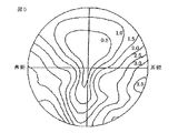
FIG. 7 is a diagram showing a distribution of surface astigmatism components substantially generated by making the prescription surface of the progressive-power lens according to the second example aspherical.
本発明の実施形態の具体的な説明に先立って、本発明の基本的な構成および作用を説明する。レンズメーターによる度数測定はレンズ面上の測定基準点を基準として行われるが、実際には点ではなくある一定の面積を持った測定領域内で測定が行われる。さらに、この測定領域はレンズメーターの種類や測定するレンズの仕様等によって異なる広さ(面積)を有する。このため、本発明において処方面の非球面化により実質的に発生する面非点隔差成分の平均値を所定の値以下に抑えるべき測定基準点を含む近傍の所定領域は、レンズメーターの測定に必要な領域(以下、「測定領域」という)を考慮して決定することが必要である。
つまり、度数測定のみを考慮するのであれば、上記面非点隔差成分の平均値が所定の値以下の所定領域はできるだけ広い方が効果的であるが、この所定領域を広くするほど装用状態における光学性能は低下する。このため、本発明の目的を達成できるように、上記測定基準点を含む近傍の所定領域はこれらの様々な条件を考慮して決定されるべきである。本発明において、装用状態における光学性能を重視する場合、上記面非点隔差成分の平均値が所定の値以下の測定基準点を含む近傍の所定領域は、測定基準点からレンズの水平方向への距離をx(mm)とし、測定基準点からレンズの鉛直方向への距離をy(mm)とするとき、|(x2+y2)1/2|≦2.50(mm)の条件を満足する領域であることが望ましい。
また、本発明では、装用状態における光学性能の改善と度数測定の容易さとのバランスを考慮する場合、上記面非点隔差成分の平均値を所定の値以下に抑えるべき所定領域は、|(x2+y2)1/2|≦4.00(mm)の条件を満足する領域であることが望ましい。
更に、本発明では、レンズメーターの測定位置合わせの精度の影響を考慮して度数測定の容易さを重視する場合、|(x2+y2)1/2|≦5.00(mm)の条件を満足する領域であることが望ましい。
ところで、トーリック面では必ず面非点隔差が存在するが、これはもともと乱視矯正に必要な面非点隔差であり、光学性能の向上のために付与されているものではない。従って、本発明では、この乱視矯正に必要な面非点隔差を、処方面の非球面化により発生する面非点隔差から分離して考える。即ち、上述したように、本発明において処方面の非球面化により実質的に発生する面非点隔差成分を、非球面化された処方面の任意の座標における面非点隔差と、処方度数の矯正に必要な球面またはトーリック面の当該座標における面非点隔差との差分の絶対値として表す。
すなわち、処方面の任意の座標(x,y)における面非点隔差をAS(x,y)とし、非球面化される前の処方度数の矯正に必要な球面またはトーリック面の当該座標(x,y)における面非点隔差をC(x,y)とし、処方面の非球面化により当該座標(x,y)において実質的に発生する面非点隔差成分をΔAS(x,y)とするとき、ΔAS(x,y)は下記の式(1)で表される。
ΔAS(x,y)=|AS(x,y)−C(x,y)| (1)
レンズメーターによる度数の測定は、処方面に対してほぼ垂直に入射する光線に基づいて行われるため、測定領域内での面非点隔差成分の分布が、ほぼそのまま測定度数に影響する。従って、本発明では、処方面の非球面化により実質的に発生する面非点隔差成分の平均値をΔASavとし、この平均値ΔASavを所定の値以下に抑えることによって本発明の目的を達成している。以下の表1は、屈折補正用累進屈折力眼鏡レンズに関するISO規格である「ISO 8980−2:2004(E)」で制定されている表であって、測定基準点における乱視屈折力の表示値に対する許容差を示す表である。

つまり、レンズメーターによる測定度数の処方度数に対するずれ量が、ISO規格で設定された許容値(許容差)以下であれば、処方度数と測定度数とが実用上は等しいと判断することができる。従って、本発明において、平均値ΔASavを表1のISO規格で設定された許容差以下に抑えれば、本発明の目的を達成することができる。ただし、累進面による測定度数への影響を考慮した場合、平均値ΔASavは表1における許容値の75%以下であることが好ましく、平均値ΔASavは表1における許容値の50%以下であることがさらに好ましい。
表1を参照してわかるように、度数測定における許容値は処方度数や乱視度数によって異なる値をとることが望ましいが、設計や製造における実務の簡略化から、平均値ΔASavの許容値を装用者の処方に依存することなく一定にすることも可能である。その場合、平均値ΔASavの許容値を表1に記載されている許容値の中から選択して決定することもできるが、本願発明者の検討によると、装用状態における光学性能を重視する場合にはΔASav≦0.15(ディオプター)を満足することが望ましく、装用状態における光学性能をさらに重視する場合にはΔASav≦0.12(ディオプター)を満足することが望ましい。
また、本発明において、装用状態における光学性能の改善と度数測定の容易さとのバランスを考慮する場合には、ΔASav≦0.10(ディオプター)を満足することが望ましく、ΔASav≦0.09(ディオプター)を満足することがさらに望ましい。更に、本発明において、度数測定の容易さを重視する場合には、ΔASav≦0.06(ディオプター)を満足することが望ましい。
また、本発明において、上記面非点隔差成分の平均値ΔASavを所定の値以下に抑えるべき測定基準点を含む近傍の所定領域は、実質的に球面形状またはトーリック面形状であることが好ましい。眼鏡店やユーザーが、透過光線における光学性能の改善よりもレンズメーターによる度数測定を重視する場合、即ち、規格による許容値を考慮することなく処方度数と測定度数とが実質的に一致することを望む場合、上記所定領域において、処方面を実質的に球面形状またはトーリック面形状にすることが有効である。本願発明者の検討によると、レンズメーターの測定領域の全体を実質的に球面形状またはトーリック面形状にしなくても、測定領域内における中心部分の一定の領域を実質的に球面形状またはトーリック面形状にすることによって、本発明の目的が達成可能であることがわかった。
従って、実質的に球面形状またはトーリック面形状である測定基準点を含む近傍の領域は、測定基準点からレンズの水平方向への距離をx(mm)とし、測定基準点からレンズの鉛直方向への距離をy(mm)とするとき、|(x2+y2)1/2|≦1.75(mm)
の条件を満足する領域であることが望ましい。また、処方度数と測定度数とをさらに良好に一致させるには、実質的に球面形状またはトーリック面形状である測定基準点を含む近傍の領域は、|(x2+y2)1/2|≦2.50(mm)の条件を満足する領域であること
が望ましく、|(x2+y2)1/2|≦4.00(mm)の条件を満足する領域であることがさらに望ましい。
一般的なレンズメーターでは、0.06D(ディオプター)よりも小さい面非点隔差成分を正確に測定することは非常に難しく、さらに0.03D以下の面非点隔差成分の測定は実用上不可能であるといわれている。従って、レンズメーターにおける実用上の屈折力の測定分解能は、0.03D以上であると考えられる。このため、測定基準点を含む近傍の領域における面非点隔差成分がレンズメーターの測定分解能である0.03D以下であれば、実測定上は球面またはトーリック面と同等であると見なすことができる。
また、本発明において、上記面非点隔差成分の平均値ΔASavを所定の値以下に抑えるべき測定基準点を含む近傍の所定領域の大きさ及び形状のうちの少なくとも一方は、装用者の処方、装用者の使用条件、製品としてのレンズの仕様、レンズの度数を測定する方法、およびレンズの度数を測定する測定器の仕様のうちの少なくとも1つの条件に基づいて決められることが好ましい。本発明のように処方面を非球面化した両面非球面型の累進屈折力レンズでは、たとえ同じ製品群であっても、処方面の非球面形状は、球面度数や乱視度数、乱視軸度、加入度、インセット角、プリズム処方等といった装用者の処方や使用条件によって大きく異なる。
さらに、測定器であるレンズメーターの測定条件についても、例えば測定光線が直径5mmの円形光束であるレンズメーターを製造するメーカーも有れば、同じく5mmでも測定光線が矩形光束であるレンズメーターを製造するメーカーも有る。また、同じメーカーでも、手動レンズメーターと自動レンズメーターとで測定光束の大きさや形状が異なる等、メーカーや測定方法の違いによって条件も様々である。従って、本発明による技術を全てのレンズに対して同じ条件で適用するのではなく、装用者の処方や使用条件、製品の仕様、度数測定方法、測定器の仕様のうち、少なくとも一つの条件を考慮して、平均値ΔASavを所定の値以下に抑えるべき測定基準点を含む近傍の所定領域の大きさや形状を決定することによって、より優れた光学性能と度数測定の容易さとの両方を得ることが可能となる。
また、本発明において、処方面の面形状を表わす関数(例えば処方面の設計上の面形状を表わす関数、処方面の実際の面形状をフィッティングして得られる関数)の少なくとも二次導関数までが処方面のほぼ全体に亘って連続であることが好ましい。この構成により、外観上の良好な連続性や透過光線における良好な光学性能を得ることができるとともに、レンズメーターによる測定度数として常に安定した値を得ることができる。
本発明の実施形態を、添付図面に基づいて説明する。図1は、本発明の実施形態にかかる累進屈折力レンズの構成を概略的に示す図である。図1を参照すると、本実施形態の累進屈折力レンズは、装用状態においてレンズの屈折面を鼻側領域と耳側領域とに分割する主注視線MM’に沿って、比較的遠方視に適した遠用部Fと、比較的近方視に適した近用部Nと、遠用部Fと近用部Nとの間において遠用部Fの面屈折力と近用部Nの面屈折力とを連続的に接続する累進部Pとを備えている。
主注視線MM’は、遠用部Fの測定基準点である遠用基準点(遠用中心)OF、遠用アイポイントE、レンズ面の幾何中心OG、および近用部Nの測定基準点である近用基準点(近用中心)ONを通る基準線である。本実施形態の各実施例では、外面(眼とは反対側の外側面)に累進面を配置し、内面(眼側の内側面)に処方面を配置している。また、遠用部Fの測定基準点である遠用基準点OFは、幾何中心OGから主注視線MM’に沿って8mm上方に位置している。また、各実施例のレンズの外径(直径)は70mmである。
[第1実施例]
図2は、第1実施例の比較例にかかる従来の累進屈折力レンズの透過光線での非点収差分布を示す図である。図2の比較例にかかる従来の累進屈折力レンズでは、球面度数S=1.00(ディオプター)であり、乱視度数C=0.00(ディオプター)であり、加入度ADD=2.00(ディオプター)であり、処方ベースカーブBC=3.70(ディオプター)であり、レンズの屈折率ne=1.60である。図2を参照すると、従来技術にしたがう比較例の累進屈折力レンズでは、遠用部F及び近用部Nにおいて、非点収差が0.5D(ディオプター)以下である領域すなわち明視域が狭くなっている。
図3は、第1実施例にかかる累進屈折力レンズの透過光線での非点収差分布を示す図である。第1実施例にかかる累進屈折力レンズは、図2の比較例と同じ処方(球面度数、乱視度数、加入度、処方ベースカーブ、屈折率)であるが、透過光線における光学性能を改善するために処方面である内面を非球面化している。図3を参照すると、本発明にしたがう第1実施例の累進屈折力レンズでは、図2の比較例に比して、遠用部F及び近用部Nの明視域は、共に良好に改善されている。
図4は、第1実施例にかかる累進屈折力レンズの処方面の非球面化により実質的に発生する面非点隔差成分の分布を示す図である。第1実施例では、図4に示すような面非点隔差成分の分布を有する非球面を処方面に付与することによって、図3で示すような光学性能の改善を達成している。以下の表2は、第1実施例にかかる累進屈折力レンズの処方面における測定基準点OFを含む近傍の領域の非球面化により実質的に発生する面非点隔差成分の分布を数値的に示す表である。
また、図2の比較例にかかる従来の累進屈折力レンズおよび第1実施例にかかる累進屈折力レンズについて、直径5mmの光束により測定するレンズメーターを用いて測定基準点OFを基準として測定したときに得られる測定度数のシミュレーション結果を以下に示す。
比較例:球面度数S=1.00D,乱視度数C=0.03D
実施例:球面度数S=1.02D,乱視度数C=0.07D
本発明にしたがう第1実施例では、内面である処方面の非球面化の影響により、測定度数としての球面度数及び乱視度数は、図2の比較例と比較して、装用者の処方度数から若干ずれた値になっている。しかしながら、表1に示すISO規格を参照すると、第1実施例における装用者の処方度数からの測定度数のずれ量は十分に許容値内であり、実用上は問題ないことがわかる。すなわち、第1実施例の累進屈折力レンズでは、本発明の目的が達成されている。
[第2実施例]
図5は、第2実施例の比較例にかかる従来の累進屈折力レンズの透過光線での非点収差分布を示す図である。図5の比較例にかかる従来の累進屈折力レンズでは、球面度数S=1.00(ディオプター)であり、乱視度数C=−2.00(ディオプター)であり、乱視軸AX=90(度)であり、加入度ADD=2.00(ディオプター)であり、処方ベースカーブBC=3.70(ディオプター)であり、レンズの屈折率ne=1.60である。図5を参照すると、従来技術にしたがう比較例の累進屈折力レンズでは、遠用部F及び近用部Nの明視域が非常に狭くなっているだけでなく、非点収差の最大値も大きくなっている。
図6は、第2実施例にかかる累進屈折力レンズの透過光線での非点収差分布を示す図である。第2実施例にかかる累進屈折力レンズは、図5の比較例と同じ処方(球面度数、乱視度数、加入度、処方ベースカーブ、屈折率)であるが、透過光線における光学性能を改善するために処方面である内面を非球面化している。図6を参照すると、本発明にしたがう第2実施例の累進屈折力レンズでは、図5の比較例に比して、遠用部F及び近用部Nの明視域は、共に非常に良好に改善され、非点収差の最大値も小さくなっている。
図7は、第2実施例にかかる累進屈折力レンズの処方面の非球面化により実質的に発生する面非点隔差成分の分布を示す図である。第2実施例では、図7に示すような面非点隔差成分の分布を有する非球面を処方面に付与することによって、図6で示すような光学性能の改善を達成している。以下の表3は、第2実施例にかかる累進屈折力レンズの処方面における測定基準点OFを含む近傍の領域の非球面化により実質的に発生する面非点隔差成分の分布を数値的に示す表である。
また、図5の比較例にかかる従来の累進屈折力レンズおよび第2実施例にかかる累進屈折力レンズについて、直径5mmの光束により測定するレンズメーターを用いて測定基準点OFを基準として測定したときに得られる測定度数のシミュレーション結果を以下に示す。
比較例:球面度数S=1.00D,乱視度数C=−2.03D,乱視軸AX=90(度)
実施例:球面度数S=1.00D,乱視度数C=−2.03D,乱視軸AX=90(度)
本発明に係る第2実施例では、内面である処方面において測定基準点OFを含む近傍の領域を実質的にトーリック面と等しい形状としている。その結果、測定度数としての球面度数及び乱視度数は、図5の比較例と同様に、装用者の処方度数とほぼ同じ値になっている。すなわち、第2実施例の累進屈折力レンズにおいても第1実施例と同様に、本発明の目的が達成されている。
以上のように、本実施形態の累進屈折力レンズでは、装用状態における光学性能が良好である上に、レンズメーターにより処方度数とほぼ等しい測定度数が得られるため、眼鏡店やユーザーによるレンズの度数測定を容易に行うことができる。尚、遠用基準点及び近用基準点のうち、いずれの測定基準点を用いて度数測定を行うかは、そのレンズが遠用処方による累進屈折力レンズであるか、近用処方による累進屈折力レンズであるかに依存することが多い。主に遠方視を重視した遠近累進屈折力レンズの場合には遠用基準点で、近方視を重視した近々累進屈折力レンズの場合は近用基準点で測定を行うことが多いが、どちらの測定基準点を用いたとしても、本発明の技術は本質的には変わらない。従って、上述の実施形態に限定されることなく、様々な仕様の累進屈折力レンズに対して本発明を適用することが可能であることは明らかである。Prior to specific description of the embodiments of the present invention, the basic configuration and operation of the present invention will be described. The power measurement by the lens meter is performed with reference to the measurement reference point on the lens surface, but actually the measurement is performed in a measurement area having a certain area instead of a point. Further, this measurement region has a different width (area) depending on the type of lens meter, the specification of the lens to be measured, and the like. For this reason, in the present invention, a predetermined region in the vicinity including a measurement reference point that should suppress the average value of the surface astigmatism component generated substantially by making the prescription surface aspherical to a predetermined value or less is used for the measurement of the lens meter. It is necessary to determine in consideration of a necessary area (hereinafter referred to as “measurement area”).
In other words, if only frequency measurement is considered, it is more effective that the predetermined area where the average value of the surface astigmatism component is equal to or less than a predetermined value is as wide as possible. Optical performance is degraded. For this reason, in order to achieve the object of the present invention, the predetermined region in the vicinity including the measurement reference point should be determined in consideration of these various conditions. In the present invention, when importance is attached to the optical performance in the wearing state, the predetermined area in the vicinity including the measurement reference point where the average value of the surface astigmatism component is not more than a predetermined value is from the measurement reference point in the horizontal direction of the lens. When the distance is x (mm) and the distance from the measurement reference point in the vertical direction of the lens is y (mm), the condition of | (x 2 + y 2 ) 1/2 | ≦ 2.50 (mm) is satisfied It is desirable that the area be
In the present invention, when considering the balance between the improvement in optical performance in the wearing state and the ease of frequency measurement, the predetermined region where the average value of the above-mentioned surface astigmatic difference component should be kept below a predetermined value is | (x 2 + y 2 ) 1/2 | ≦ 4.00 (mm) is preferable.
Furthermore, in the present invention, in the case where importance is attached to the ease of power measurement in consideration of the influence of the accuracy of measurement alignment of the lens meter, the condition of | (x 2 + y 2 ) 1/2 | ≦ 5.00 (mm) It is desirable that the region satisfies the above.
By the way, there is always a surface astigmatism on the toric surface, but this is a surface astigmatism originally necessary for astigmatism correction, and is not provided for improving optical performance. Therefore, in the present invention, the surface astigmatism necessary for correcting astigmatism is considered separately from the surface astigmatism generated by making the prescription surface aspherical. That is, as described above, in the present invention, the surface astigmatism component that is substantially generated by making the prescription surface aspherical, the surface astigmatism difference at an arbitrary coordinate of the prespherical prescription surface, and the prescription power It is expressed as the absolute value of the difference from the surface astigmatism difference in the coordinates of the spherical surface or toric surface necessary for correction.
That is, AS (x, y) is the surface astigmatism difference at an arbitrary coordinate (x, y) of the prescription surface, and the coordinate (x of the spherical surface or toric surface necessary for correcting the prescription power before being aspherical. , Y) is defined as C (x, y), and the surface astigmatism component substantially generated at the coordinates (x, y) due to the aspherical surface of the prescription surface is denoted as ΔAS (x, y). In this case, ΔAS (x, y) is expressed by the following equation (1).
ΔAS (x, y) = | AS (x, y) −C (x, y) | (1)
Since the measurement of the power by the lens meter is performed based on a light beam incident substantially perpendicular to the prescription surface, the distribution of the surface astigmatism component in the measurement region almost directly affects the measurement power. Therefore, in the present invention, the average value of the surface astigmatic difference component substantially generated by making the prescription surface aspherical is ΔASav, and the object of the present invention is achieved by suppressing this average value ΔASav below a predetermined value. ing. Table 1 below is a table established in “ISO 8980-2: 2004 (E)”, which is an ISO standard related to a progressive-power spectacle lens for refraction correction, and is a display value of astigmatic power at a measurement reference point. It is a table | surface which shows the tolerance with respect to.
That is, if the amount of deviation of the power measured by the lens meter with respect to the prescription power is equal to or less than the allowable value (tolerance) set by the ISO standard, it can be determined that the prescription power and the measurement power are practically equal. Therefore, in the present invention, the object of the present invention can be achieved if the average value ΔASav is suppressed to be equal to or smaller than the tolerance set in the ISO standard shown in Table 1. However, in consideration of the influence of the progressive surface on the measurement frequency, the average value ΔASav is preferably 75% or less of the allowable value in Table 1, and the average value ΔASav is 50% or less of the allowable value in Table 1. Is more preferable.
As can be seen with reference to Table 1, it is desirable that the allowable value in the frequency measurement varies depending on the prescription frequency and the astigmatic power, but the average ΔASav allowable value is set to the wearer for simplification of practical work in design and manufacturing. It is also possible to make it constant without depending on the prescription. In that case, the allowable value of the average value ΔASav can be selected and determined from the allowable values listed in Table 1, but according to the study of the present inventor, when the optical performance in the wearing state is important. Preferably satisfies ΔASav ≦ 0.15 (diopter), and it is desirable to satisfy ΔASav ≦ 0.12 (diopter) when the optical performance in the wearing state is more important.
In the present invention, it is desirable to satisfy ΔASav ≦ 0.10 (diopter) and ΔASav ≦ 0.09 (diopter) when considering the balance between the improvement of optical performance in the wearing state and the ease of frequency measurement. ) Is more desirable. Furthermore, in the present invention, it is desirable to satisfy ΔASav ≦ 0.06 (diopter) when emphasizing ease of frequency measurement.
In the present invention, it is preferable that the predetermined region in the vicinity including the measurement reference point at which the average value ΔASav of the surface astigmatic difference component is suppressed to a predetermined value or less is substantially spherical or toric surface. When a optician or user places more emphasis on power measurement with a lens meter than improvement of optical performance in transmitted light, that is, the prescription power and the measurement power substantially match without taking into account the tolerances of the standard. If desired, it is effective to make the prescription surface substantially spherical or toric in the predetermined area. According to the study of the present inventor, even if the entire measurement area of the lens meter is not substantially spherical or toric, a certain area of the central portion in the measurement area is substantially spherical or toric. It has been found that the object of the present invention can be achieved.
Therefore, in the vicinity region including the measurement reference point that is substantially spherical or toric surface shape, the distance from the measurement reference point to the horizontal direction of the lens is x (mm), and the measurement reference point extends in the vertical direction of the lens. | (X 2 + y 2 ) 1/2 | ≦ 1.75 (mm)
It is desirable that the region satisfies this condition. Further, in order to make the prescription power and the measurement power more satisfactorily coincide with each other, a nearby region including a measurement reference point that is substantially spherical or toric surface is represented by | (x 2 + y 2 ) 1/2 | ≦ A region that satisfies the condition of 2.50 (mm) is desirable, and a region that satisfies the condition of | (x 2 + y 2 ) 1/2 | ≦ 4.00 (mm) is more desirable.
With a general lens meter, it is very difficult to accurately measure a surface astigmatism component smaller than 0.06D (diopter), and it is practically impossible to measure a surface astigmatism component of 0.03D or less. It is said that it is. Accordingly, it is considered that the practical refractive power measurement resolution in the lens meter is 0.03D or more. For this reason, if the surface astigmatism component in the adjacent region including the measurement reference point is 0.03D or less which is the measurement resolution of the lens meter, it can be regarded as equivalent to a spherical surface or a toric surface in actual measurement. .
Further, in the present invention, at least one of the size and shape of a predetermined region including the measurement reference point that should suppress the average value ΔASav of the surface astigmatism component to a predetermined value or less is prescription of the wearer, It is preferably determined based on at least one of the conditions of use of the wearer, the specification of the lens as a product, the method of measuring the lens power, and the specification of the measuring device for measuring the lens power. In the double-sided aspherical progressive addition lens with the prescription surface aspherical as in the present invention, the prespherical shape of the prescription surface is spherical power, astigmatism power, astigmatism axis, It varies greatly depending on the wearer's prescription and usage conditions such as addition, inset angle and prism prescription.
Furthermore, with regard to the measurement conditions of the lens meter that is a measuring instrument, for example, there are manufacturers that manufacture a lens meter whose measurement light beam is a circular light beam with a diameter of 5 mm, and a lens meter whose measurement light beam is a rectangular light beam even at 5 mm. Some manufacturers do. Even in the same manufacturer, the conditions vary depending on the manufacturer and the measurement method, such as the size and shape of the measurement light beam differing between the manual lens meter and the automatic lens meter. Therefore, the technology according to the present invention is not applied to all lenses under the same conditions, but at least one of the wearer's prescription and usage conditions, product specifications, frequency measurement methods, and measurement instrument specifications is used. In consideration, by determining the size and shape of a predetermined area in the vicinity including the measurement reference point where the average value ΔASav should be kept below a predetermined value, both superior optical performance and ease of frequency measurement can be obtained. Is possible.
In the present invention, at least the second derivative of a function representing the surface shape of the prescription surface (for example, a function representing the surface shape in the design of the prescription surface, a function obtained by fitting the actual surface shape of the prescription surface). Is preferably continuous over substantially the entire prescription surface. With this configuration, it is possible to obtain good continuity in appearance and good optical performance in transmitted light, and always obtain a stable value as the power measured by the lens meter.
Embodiments of the present invention will be described with reference to the accompanying drawings. FIG. 1 is a diagram schematically showing a configuration of a progressive-power lens according to an embodiment of the present invention. Referring to FIG. 1, the progressive-power lens of this embodiment is suitable for relatively far vision along the main gazing line MM ′ that divides the refractive surface of the lens into a nose side region and an ear side region in the wearing state. The distance refractive power of the distance portion F and the surface refraction of the near portion N between the distance portion F, the near portion N relatively suitable for near vision, and the distance portion F and the near portion N. And a progressive portion P for continuously connecting the force.
The main gaze line MM ′ is a distance reference point (distance center) OF which is a measurement reference point of the distance portion F, a distance eye point E, a geometric center OG of the lens surface, and a measurement reference point of the near portion N This is a reference line passing through the near reference point (near-use center) ON. In each example of the present embodiment, a progressive surface is disposed on the outer surface (the outer surface opposite to the eye), and a prescription surface is disposed on the inner surface (the inner surface on the eye side). The distance reference point OF, which is the measurement reference point of the distance portion F, is located 8 mm above the geometric center OG along the main gazing line MM ′. The outer diameter (diameter) of the lens of each example is 70 mm.
[First embodiment]
FIG. 2 is a diagram showing the astigmatism distribution in the transmitted light of the conventional progressive-power lens according to the comparative example of the first embodiment. In the conventional progressive-power lens according to the comparative example of FIG. 2, the spherical power S = 1.00 (diopter), the astigmatic power C = 0.00 (diopter), and the addition ADD = 2.00 (diopter). ), Prescription base curve BC = 3.70 (diopter), and lens refractive index ne = 1.60. Referring to FIG. 2, in the progressive addition lens of the comparative example according to the prior art, in the distance portion F and the near portion N, the region where the astigmatism is 0.5D (diopter) or less, that is, the clear vision region is narrow. It has become.
FIG. 3 is a diagram showing an astigmatism distribution in the transmitted light of the progressive addition lens according to the first example. The progressive addition lens according to the first example has the same prescription (spherical power, astigmatism power, addition power, prescription base curve, refractive index) as in the comparative example of FIG. 2, but to improve the optical performance in transmitted light. The prescription surface is aspherical. Referring to FIG. 3, in the progressive-power lens according to the first embodiment according to the present invention, the clear vision areas of the distance portion F and the near portion N are both improved as compared with the comparative example of FIG. Has been.
FIG. 4 is a diagram showing a distribution of surface astigmatism components substantially generated by making the prescription surface of the progressive-power lens according to the first example aspherical. In the first embodiment, an optical performance improvement as shown in FIG. 3 is achieved by applying an aspherical surface having a distribution of surface astigmatic difference components as shown in FIG. 4 to the prescription surface. Table 2 below shows numerically the distribution of the surface astigmatism component that is substantially generated by the asphericalization of the adjacent region including the measurement reference point OF on the prescription surface of the progressive addition lens according to the first example. It is a table | surface which shows.
When the conventional progressive-power lens according to the comparative example of FIG. 2 and the progressive-power lens according to the first example are measured using a lens meter that measures with a light beam having a diameter of 5 mm as a reference, the measurement reference point OF. The simulation results of the measurement power obtained in the following are shown below.
Comparative example: spherical power S = 1.00D, astigmatic power C = 0.03D
Example: Spherical power S = 1.02D, Astigmatic power C = 0.07D
In the first embodiment according to the present invention, the spherical power and the astigmatism power as the measurement power are determined from the prescription power of the wearer as compared with the comparative example of FIG. 2 due to the influence of the aspherical surface of the prescription surface which is the inner surface. The value is slightly shifted. However, referring to the ISO standard shown in Table 1, it can be seen that the amount of deviation of the measured power from the prescription power of the wearer in the first embodiment is sufficiently within an allowable value, and there is no problem in practical use. That is, the objective of the present invention is achieved in the progressive-power lens of the first embodiment.
[Second Embodiment]
FIG. 5 is a diagram showing the astigmatism distribution in the transmitted light of the conventional progressive-power lens according to the comparative example of the second example. In the conventional progressive-power lens according to the comparative example of FIG. 5, the spherical power S = 1.00 (diopter), the astigmatic power C = −2.00 (diopter), and the astigmatic axis AX = 90 (degrees). The addition power ADD = 2.00 (diopter), the prescription base curve BC = 3.70 (diopter), and the refractive index ne = 1.60 of the lens. Referring to FIG. 5, in the progressive addition lens of the comparative example according to the prior art, not only the clear vision areas of the distance portion F and the near portion N are very narrow, but the maximum value of astigmatism is also increased. It is getting bigger.
FIG. 6 is a diagram showing the astigmatism distribution in the transmitted light of the progressive addition lens according to the second example. The progressive addition lens according to the second example has the same prescription (spherical power, astigmatism power, addition power, prescription base curve, refractive index) as in the comparative example of FIG. 5, but to improve the optical performance in transmitted light. The prescription surface is aspherical. Referring to FIG. 6, in the progressive-power lens according to the second embodiment according to the present invention, both the clear vision areas of the distance portion F and the near portion N are very good as compared with the comparative example of FIG. The maximum value of astigmatism is also reduced.
FIG. 7 is a diagram showing a distribution of surface astigmatism components substantially generated by making the prescription surface of the progressive-power lens according to the second example aspherical. In the second embodiment, an optical surface improvement as shown in FIG. 6 is achieved by applying an aspherical surface having a distribution of surface astigmatic difference components as shown in FIG. 7 to the prescription surface. Table 3 below shows numerically the distribution of the surface astigmatism component that is substantially generated by the asphericalization of the adjacent region including the measurement reference point OF on the prescription surface of the progressive addition lens according to the second embodiment. It is a table | surface which shows.
Further, when the conventional progressive-power lens according to the comparative example of FIG. 5 and the progressive-power lens according to the second example are measured using a lens meter that measures with a light beam having a diameter of 5 mm, the measurement reference point OF is used as a reference. The simulation results of the measurement power obtained in the following are shown below.
Comparative example: spherical power S = 1.00D, astigmatic power C = −2.03D, astigmatic axis AX = 90 (degrees)
Example: Spherical power S = 1.00D, Astigmatic power C = −2.03D, Astigmatic axis AX = 90 (degrees)
In the second embodiment according to the present invention, a region in the vicinity including the measurement reference point OF on the prescription surface which is the inner surface has a shape substantially equal to the toric surface. As a result, the spherical power and the astigmatism power as the measurement power are substantially the same as the prescription power of the wearer, as in the comparative example of FIG. That is, the objective of the present invention is also achieved in the progressive-power lens of the second embodiment, as in the first embodiment.
As described above, in the progressive-power lens according to the present embodiment, the optical performance in the wearing state is good, and the lens lens can obtain a measurement power almost equal to the prescription power. Measurement can be performed easily. Of the reference point for distance and the reference point for near distance, which measurement reference point is used for power measurement depends on whether the lens is a progressive power lens with a distance prescription or progressive refraction with a near distance prescription. It often depends on whether it is a power lens. In the case of a progressive power lens focusing on far vision, measurement is performed at the distance reference point, and in the case of a near progressive power lens focusing on near vision, measurement is often performed at the near reference point. Even if the measurement reference points are used, the technique of the present invention is not essentially changed. Therefore, it is apparent that the present invention can be applied to progressive power lenses having various specifications without being limited to the above-described embodiments.
Claims (12)
レンズの透過光線における光学性能を補正するために形成された処方面は非球面形状を有し、
眼鏡フレーム内に設定された、前記遠用部領域の測定基準点である遠用基準点と前記近用部領域の測定基準である近用基準点の少なくとも一方の前記測定基準点において、前記処方面により発生する面非点隔差成分と処方度数の矯正に必要な球面またはトーリック面により発生する面非点隔差成分との差の絶対値の平均値が、レンズの度数を測定するための前記測定基準点を含む近傍の所定領域に亘って所定の値以下であることを特徴とする累進屈折力レンズ。A distance area that is relatively suitable for far vision, and a relatively close distance to the distance area, along a main gaze line that divides the refractive surface of the lens into a nose area and an ear area in the wearing state. The near-field portion suitable for viewing and the surface-refractive power of the distance-portion region and the surface-refractive power of the near-portion region are continuously between the distance portion region and the near portion region. In a progressive-power lens having a progressive area to be connected,
The prescription surface formed to correct the optical performance in the transmitted light of the lens has an aspheric shape,
At the measurement reference point set in the spectacle frame, at least one of a distance reference point that is a measurement reference point of the distance portion area and a near reference point that is a measurement reference point of the near area. the average value of the absolute value of the difference between the surface astigmatism component generated by the spherical or toric surface required corrective prescription power and the generated surfaces astigmatism components by surface is, the measurement for measuring the power of the lens A progressive-power lens having a predetermined value or less over a predetermined region in the vicinity including a reference point.
|(x2+y2)1/2|≦2.50
の条件を満足する領域であることを特徴とする請求項2に記載の累進屈折力レンズ。When the predetermined area is x (mm) as the distance from the measurement reference point in the horizontal direction of the lens and y (mm) as the distance from the measurement reference point in the vertical direction of the lens,
| (X 2 + y 2 ) 1/2 | ≦ 2.50
The progressive-power lens according to claim 2, wherein the region satisfies the following condition.
|(x2+y2)1/2|≦2.50
の条件を満足する領域であることを特徴とする請求項1に記載の累進屈折力レンズ。When the predetermined area is x (mm) as the distance from the measurement reference point in the horizontal direction of the lens and y (mm) as the distance from the measurement reference point in the vertical direction of the lens,
| (X 2 + y 2 ) 1/2 | ≦ 2.50
The progressive-power lens according to claim 1, wherein the region satisfies the following condition.
|(x2+y2)1/2|≦2.50
の条件を満足する領域であることを特徴とする請求項6に記載の累進屈折力レンズ。When the predetermined area is x (mm) as the distance from the measurement reference point in the horizontal direction of the lens and y (mm) as the distance from the measurement reference point in the vertical direction of the lens,
| (X 2 + y 2 ) 1/2 | ≦ 2.50
The progressive-power lens according to claim 6 , wherein the lens satisfies the following condition.
|(x2+y2)1/2|≦2.50
の条件を満足する領域であることを特徴とする請求項5に記載の累進屈折力レンズ。When the predetermined area is x (mm) as the distance from the measurement reference point in the horizontal direction of the lens and y (mm) as the distance from the measurement reference point in the vertical direction of the lens,
| (X 2 + y 2 ) 1/2 | ≦ 2.50
The progressive-power lens according to claim 5, wherein the lens satisfies the following condition.
|(x2+y2)1/2|≦.50
の条件を満足する領域であることを特徴とする請求項10に記載の累進屈折力レンズ。When the predetermined area is x (mm) as the distance from the measurement reference point in the horizontal direction of the lens and y (mm) as the distance from the measurement reference point in the vertical direction of the lens,
| (X 2 + y 2 ) 1/2 | ≦. 50
The progressive-power lens according to claim 10 , wherein the region satisfies the following condition.
|(x2+y2)1/2|≦2.50
の条件を満足する領域であることを特徴とする請求項9に記載の累進屈折力レンズ。When the predetermined area is x (mm) as the distance from the measurement reference point in the horizontal direction of the lens and y (mm) as the distance from the measurement reference point in the vertical direction of the lens,
| (X 2 + y 2 ) 1/2 | ≦ 2.50
The progressive-power lens according to claim 9 , wherein the progressive-power lens is a region that satisfies the above condition.
Priority Applications (1)
| Application Number | Priority Date | Filing Date | Title |
|---|---|---|---|
| JP2007525964A JP5000505B2 (en) | 2005-07-21 | 2006-07-06 | Progressive power lens |
Applications Claiming Priority (4)
| Application Number | Priority Date | Filing Date | Title |
|---|---|---|---|
| JP2005210705 | 2005-07-21 | ||
| JP2005210705 | 2005-07-21 | ||
| PCT/JP2006/313922 WO2007010806A1 (en) | 2005-07-21 | 2006-07-06 | Progressive refractive power lens |
| JP2007525964A JP5000505B2 (en) | 2005-07-21 | 2006-07-06 | Progressive power lens |
Publications (2)
| Publication Number | Publication Date |
|---|---|
| JPWO2007010806A1 JPWO2007010806A1 (en) | 2009-01-29 |
| JP5000505B2 true JP5000505B2 (en) | 2012-08-15 |
Family
ID=37668688
Family Applications (1)
| Application Number | Title | Priority Date | Filing Date |
|---|---|---|---|
| JP2007525964A Active JP5000505B2 (en) | 2005-07-21 | 2006-07-06 | Progressive power lens |
Country Status (2)
| Country | Link |
|---|---|
| JP (1) | JP5000505B2 (en) |
| WO (1) | WO2007010806A1 (en) |
Families Citing this family (10)
| Publication number | Priority date | Publication date | Assignee | Title |
|---|---|---|---|---|
| JP5000505B2 (en) | 2005-07-21 | 2012-08-15 | 株式会社ニコン・エシロール | Progressive power lens |
| DE102009005214A1 (en) * | 2009-01-20 | 2010-07-22 | Rodenstock Gmbh | Automatic progressive lens design modification |
| JP5872785B2 (en) * | 2011-04-07 | 2016-03-01 | イーエイチエス レンズ フィリピン インク | Progressive power lens design method |
| TWI588560B (en) | 2012-04-05 | 2017-06-21 | 布萊恩荷登視覺協會 | Lenses, devices, methods and systems for refractive error |
| US9201250B2 (en) | 2012-10-17 | 2015-12-01 | Brien Holden Vision Institute | Lenses, devices, methods and systems for refractive error |
| WO2014059465A1 (en) | 2012-10-17 | 2014-04-24 | Brien Holden Vision Institute | Lenses, devices, methods and systems for refractive error |
| JP6312538B2 (en) | 2014-06-18 | 2018-04-18 | 株式会社ニコン・エシロール | Lens design method, lens manufacturing method, lens design program, and lens design system |
| JP6458262B2 (en) * | 2015-04-07 | 2019-01-30 | 東海光学株式会社 | Design method and manufacturing method for eyeglass lens |
| JP7368991B2 (en) * | 2019-09-25 | 2023-10-25 | ホヤ レンズ タイランド リミテッド | Progressive power lens design method and progressive power lens design system |
| KR20220093217A (en) * | 2019-12-20 | 2022-07-05 | 가부시키가이샤 니콘. 에시로루 | Spectacle lens design method, spectacle lens manufacturing method, spectacle lens, spectacle lens design device, spectacle lens order system and design program |
Citations (4)
| Publication number | Priority date | Publication date | Assignee | Title |
|---|---|---|---|---|
| JPS5487243A (en) | 1977-12-22 | 1979-07-11 | Seiko Epson Corp | Eyeglass lens |
| JP2000066148A (en) | 1998-06-12 | 2000-03-03 | Seiko Epson Corp | Progressive refracting power lens |
| JP2004341086A (en) * | 2003-05-14 | 2004-12-02 | Tokai Kogaku Kk | Progressive refractive power lens |
| WO2007010806A1 (en) | 2005-07-21 | 2007-01-25 | Nikon-Essilor Co., Ltd. | Progressive refractive power lens |
-
2006
- 2006-07-06 JP JP2007525964A patent/JP5000505B2/en active Active
- 2006-07-06 WO PCT/JP2006/313922 patent/WO2007010806A1/en active Application Filing
Patent Citations (4)
| Publication number | Priority date | Publication date | Assignee | Title |
|---|---|---|---|---|
| JPS5487243A (en) | 1977-12-22 | 1979-07-11 | Seiko Epson Corp | Eyeglass lens |
| JP2000066148A (en) | 1998-06-12 | 2000-03-03 | Seiko Epson Corp | Progressive refracting power lens |
| JP2004341086A (en) * | 2003-05-14 | 2004-12-02 | Tokai Kogaku Kk | Progressive refractive power lens |
| WO2007010806A1 (en) | 2005-07-21 | 2007-01-25 | Nikon-Essilor Co., Ltd. | Progressive refractive power lens |
Non-Patent Citations (17)
| Title |
|---|
| JPN3014001023; 神津和麿: 調査報告書(1) , 20140707 |
| JPN3014001024; '(DEFINITY 右眼用レンズ袋 表面及び裏面)' 写真 |
| JPN3014001025; '(DEFINITY 左眼用レンズ袋 表面及び裏面)' 写真 |
| JPN3014001026; INVOICE NO. 120885, 20030623 |
| JPN3014001027; '(DEFINITY 右眼用レンズ)' 写真 |
| JPN3014001028; '(DEFINITY 左眼用レンズ)' 写真 |
| JPN3014001029; FIT DEFINITY LENSES AS YOUR PROGRESSIVE LENS OF CHOICE 及び訳文 , 2004, JOHNSON & JOHNSON VISION CARE, INC. |
| JPN3014001030; 神津和麿: 調査報告書(2) , 20140707 |
| JPN3014001031; '(DEFINITY 2 左眼用レンズ袋 表面及び裏面)' 写真 |
| JPN3014001032; '(DEFINITY 2 右眼用レンズ袋 表面及び裏面)' 写真 |
| JPN3014001033; CONGRATULATIONS FOR CHOOSING DEFINITY 2 LENSES! 及び抄訳 , 2001, JOHNSON & JOHNSON VISION CARE, INC. |
| JPN3014001034; 'DEFINITY 2' スキャンイメージ |
| JPN3014001035; 石戸谷達雄: 訴状 , 20140402 |
| JPN3014001036; (株)ニコン・エシロール: '手続補正書' 特願2007-525964 , 20111107 |
| JPN3014001037; (株)ニコン・エシロール: '意見書' 特願2007-525964 , 20111107 |
| JPN3014001038; 米国特許第5444503号公報 , 19950822, 米国特許商標庁 |
| JPN3014001039; 宮崎謙: 調査報告書 , 20140327 |
Also Published As
| Publication number | Publication date |
|---|---|
| WO2007010806A1 (en) | 2007-01-25 |
| JPWO2007010806A1 (en) | 2009-01-29 |
Similar Documents
| Publication | Publication Date | Title |
|---|---|---|
| JP5000505B2 (en) | Progressive power lens | |
| JP5388579B2 (en) | Eyeglass lenses | |
| KR101301566B1 (en) | Ophthalmic lens | |
| CN101331421B (en) | Method for determination of an ophthalmic lens | |
| US7413303B2 (en) | Ophthalmic lens | |
| JP4954419B2 (en) | Glasses manufacturing method | |
| KR102042554B1 (en) | A method for determining an ophthalmic lens | |
| KR20090071590A (en) | Ophthalmic lens element | |
| JP2007241276A (en) | Method for the determination of progressive focus ophthalmic lens | |
| US9523864B2 (en) | Method for determining a progressive ophthalmic lens | |
| WO2014037482A2 (en) | A method for determining a progressive ophthalmic lens | |
| CN106444073B (en) | Ophthalmic lens customized for wearer and preparation method thereof | |
| CA3095519C (en) | A method for determining a single vision ophthalmic lens | |
| JP2008299168A (en) | Aspherical spectacle lens, and method of manufacturing the same | |
| JP4708344B2 (en) | Progressive glass design with error protection | |
| KR102125745B1 (en) | Method for determining the feasibility of an ophthalmic lens | |
| JP2007504485A5 (en) | ||
| US11693258B2 (en) | Computer-implemented method for fitting a spectacle lens to a spectacle frame | |
| JP2007509373A (en) | Special eyeglass lenses | |
| CN114815304A (en) | Method for designing spectacle lens, method for manufacturing spectacle lens, and design system |
Legal Events
| Date | Code | Title | Description |
|---|---|---|---|
| A625 | Written request for application examination (by other person) |
Free format text: JAPANESE INTERMEDIATE CODE: A625 Effective date: 20090326 |
|
| A131 | Notification of reasons for refusal |
Free format text: JAPANESE INTERMEDIATE CODE: A131 Effective date: 20110913 |
|
| A521 | Request for written amendment filed |
Free format text: JAPANESE INTERMEDIATE CODE: A523 Effective date: 20111107 |
|
| TRDD | Decision of grant or rejection written | ||
| A01 | Written decision to grant a patent or to grant a registration (utility model) |
Free format text: JAPANESE INTERMEDIATE CODE: A01 Effective date: 20120515 |
|
| A01 | Written decision to grant a patent or to grant a registration (utility model) |
Free format text: JAPANESE INTERMEDIATE CODE: A01 |
|
| A61 | First payment of annual fees (during grant procedure) |
Free format text: JAPANESE INTERMEDIATE CODE: A61 Effective date: 20120516 |
|
| R150 | Certificate of patent or registration of utility model |
Ref document number: 5000505 Country of ref document: JP Free format text: JAPANESE INTERMEDIATE CODE: R150 Free format text: JAPANESE INTERMEDIATE CODE: R150 |
|
| FPAY | Renewal fee payment (event date is renewal date of database) |
Free format text: PAYMENT UNTIL: 20150525 Year of fee payment: 3 |
|
| R250 | Receipt of annual fees |
Free format text: JAPANESE INTERMEDIATE CODE: R250 |
|
| R250 | Receipt of annual fees |
Free format text: JAPANESE INTERMEDIATE CODE: R250 |
|
| R157 | Certificate of patent or utility model (correction) |
Free format text: JAPANESE INTERMEDIATE CODE: R157 |
|
| R250 | Receipt of annual fees |
Free format text: JAPANESE INTERMEDIATE CODE: R250 |
|
| R250 | Receipt of annual fees |
Free format text: JAPANESE INTERMEDIATE CODE: R250 |
|
| R250 | Receipt of annual fees |
Free format text: JAPANESE INTERMEDIATE CODE: R250 |