JP5000394B2 - Lifting magnet control system and lifting magnet control method - Google Patents
Lifting magnet control system and lifting magnet control method Download PDFInfo
- Publication number
- JP5000394B2 JP5000394B2 JP2007162976A JP2007162976A JP5000394B2 JP 5000394 B2 JP5000394 B2 JP 5000394B2 JP 2007162976 A JP2007162976 A JP 2007162976A JP 2007162976 A JP2007162976 A JP 2007162976A JP 5000394 B2 JP5000394 B2 JP 5000394B2
- Authority
- JP
- Japan
- Prior art keywords
- lifting magnet
- power
- mass
- suspended load
- control
- Prior art date
- Legal status (The legal status is an assumption and is not a legal conclusion. Google has not performed a legal analysis and makes no representation as to the accuracy of the status listed.)
- Expired - Fee Related
Links
Images


Landscapes
- Load-Engaging Elements For Cranes (AREA)
Description
本発明は、リフティングマグネット制御システムおよびリフティングマグネット制御方法に関するものである。 The present invention relates to a lifting magnet control system and a lifting magnet control method.
一般に、荷役作業や建設作業等において鉄片を持ち上げるためのリフティングマグネットが知られている。リフティングマグネットには、工場等の設備となっているものや、車両に搭載されるものがある。リフティングマグネットを使用する際には、コイルに電流を流して励磁し、該コイルに鉄片などの吊荷を吸着させて持ち上げる。そして、吊荷を釈放する際には、逆向きに電流を流してコイルを消磁する。このような励磁や消磁のための電力をリフティングマグネットに供給する方法が記載された文献としては、例えば特許文献1がある。特許文献1に記載された方法においては、リフティングマグネットに吊荷を一旦吸着させたのち、吊荷が目標質量となるまで励磁電圧を低下させて吊荷の一部を落下させ、吊荷を減らすことによってその質量を調整している。
リフティングマグネットは、励磁電流に応じた吸着力を発生し、この吸着力を超えない質量の吊荷を持ち上げることができる。しかしながら、従来のシステムでは、リフティングマグネットの吸着力に対して吊荷が軽い場合であってもその吸着力を保ち続けるので、過剰な電力を消費してしまう傾向がある。また、特許文献1に記載された方法では、目標質量を超える吊荷を一旦持ち上げ、吊荷の一部を落下させることによってその質量を調整しているが、吊荷を持ち上げるたびに吊荷を落とす時間が必要となるので作業効率が低下してしまう。
The lifting magnet generates an attracting force according to the exciting current, and can lift a suspended load having a mass that does not exceed the attracting force. However, in the conventional system, even if the suspended load is lighter than the lifting magnet's attracting force, the attracting force is maintained, so that excessive power tends to be consumed. Moreover, in the method described in
本発明は、上記した問題点を鑑みてなされたものであり、作業効率を維持しつつ、リフティングマグネットへの供給電力を節減できるリフティングマグネット制御システムおよびリフティングマグネット制御方法を提供することを目的とする。 The present invention has been made in view of the above-described problems, and an object of the present invention is to provide a lifting magnet control system and a lifting magnet control method capable of reducing the power supplied to the lifting magnet while maintaining work efficiency. .
上記した課題を解決するために、本発明によるリフティングマグネット制御システムは、リフティングマグネットに電力を供給するマグネット駆動回路と、電力の大きさを制御する制御部と、リフティングマグネットに吊荷が吊下された状態で、該吊荷の質量を検出する質量検出手段とを備え、制御部が、質量検出手段により検出された吊荷の質量が所定値より小さい場合に電力を該質量に対応する大きさに低下させる第1の制御モードと、吊荷の質量にかかわらず電力を初期設定された大きさに維持する第2の制御モードとを有することを特徴とする。
In order to solve the above-described problems, a lifting magnet control system according to the present invention includes a magnet drive circuit that supplies power to a lifting magnet, a control unit that controls the magnitude of power, and a suspended load suspended from the lifting magnet. in the state, a mass detection means for detecting the mass of the hanging load, the control unit, the mass of the suspended load that have been detected by mass detection means corresponds to the mass of the power is smaller than a predetermined value magnitude And a second control mode for maintaining electric power at an initially set magnitude regardless of the mass of the suspended load .
また、本発明によるリフティングマグネット制御方法は、リフティングマグネットに供給する電力の大きさを制御する方法であって、初期設定された大きさの電力をリフティングマグネットに供給する初期電力供給ステップと、リフティングマグネットに吊荷が吸着されて吊下された状態で、該吊荷の質量が所定値より小さい場合に電力を該質量に対応する大きさに低下させる第1の制御モード、および吊荷の質量にかかわらず電力を初期設定された大きさに維持する第2の制御モードのうちいずれか一方を、操作者の選択に応じて実行する電力制御ステップとを備えることを特徴とする。
The lifting magnet control method according to the present invention is a method for controlling the magnitude of power supplied to the lifting magnet, and includes an initial power supply step for supplying the lifting magnet with a preset amount of power, and the lifting magnet. In a state where the suspended load is adsorbed and suspended, the first control mode for reducing the power to a magnitude corresponding to the mass when the mass of the suspended load is smaller than a predetermined value, and the mass of the suspended load. Regardless of the second control mode, the power control step of executing any one of the second control modes for maintaining the power at the initially set magnitude according to the operator's selection is provided.
上記したリフティングマグネット制御システムおよびリフティングマグネット制御方法では、リフティングマグネットに吊荷が吊下された状態で、リフティングマグネットへの供給電力を吊荷の質量に対応する大きさまで低下させる。これによって、リフティングマグネットの吸着力に対して吊荷が軽い場合にはその吸着力を必要十分な大きさまで低下させ、過剰な電力消費を抑えることができる。また、リフティングマグネットへの供給電力の大きさを吊下された吊荷の質量に対応させるので、吊荷を持ち上げるたびに吊荷の一部を落とす必要がなく、作業効率を好適に維持できる。 In the lifting magnet control system and the lifting magnet control method described above, the power supplied to the lifting magnet is reduced to a magnitude corresponding to the mass of the lifting load while the hanging load is suspended from the lifting magnet. Thereby, when the suspended load is light with respect to the attracting force of the lifting magnet, the attracting force can be reduced to a necessary and sufficient level, and excessive power consumption can be suppressed. Moreover, since the magnitude of the power supplied to the lifting magnet is made to correspond to the mass of the suspended load, it is not necessary to drop a part of the suspended load every time the suspended load is lifted, and the work efficiency can be suitably maintained.
また、リフティングマグネット制御システムは、吊荷の質量と、電力における電流及び電圧のうち少なくとも一方の大きさとが対応付けられたデータを記憶する記憶手段を更に備え、制御部が、第1の制御モードにおいて記憶手段のデータに従って電力を低下させることを特徴としてもよい。また、リフティングマグネット制御方法は、電力制御ステップの第1の制御モードの際に、吊荷の質量と、電力における電流及び電圧のうち少なくとも一方の大きさとが対応付けられたデータに従って電力を低下させることを特徴としてもよい。これらのシステムおよび方法によれば、リフティングマグネットへの供給電力(電流または電圧、或いはその双方)の大きさをデータに従って容易に決定できる。
The lifting magnet control system further includes storage means for storing data in which the mass of the suspended load is associated with at least one of the current and voltage in the power, and the control unit includes the first control mode. The power may be reduced according to the data stored in the storage means. In the first control mode of the power control step, the lifting magnet control method reduces the power according to data in which the mass of the suspended load is associated with at least one of the current and voltage in the power. This may be a feature. According to these systems and methods, the magnitude of the power supplied to the lifting magnet (current and / or voltage) can be easily determined according to the data.
また、リフティングマグネット制御システムは、制御部が、第1の制御モードにおいて、質量検出手段により検出された吊荷の質量が所定値より大きい場合には電力の大きさを維持することを特徴としてもよい。また、リフティングマグネット制御方法は、電力制御ステップの第1の制御モードの際に、吊荷の質量が所定値より大きい場合には電力の大きさを維持することを特徴としてもよい。これらのシステムおよび方法によれば、吊下された吊荷の質量が大きい場合でも吊荷の一部を落下させることなく作業を安全に行うことができる。
Further, the lifting magnet control system may be characterized in that, in the first control mode, the control unit maintains the magnitude of electric power when the mass of the suspended load detected by the mass detection unit is larger than a predetermined value. Good. Further, the lifting magnet control method may be characterized in that, in the first control mode of the power control step, the magnitude of the power is maintained when the mass of the suspended load is larger than a predetermined value. According to these systems and methods, even if the mass of the suspended load is large, the work can be performed safely without dropping a part of the suspended load.
また、本発明によるリフティングマグネット制御システムは、質量検出手段により検出された吊荷の質量が所定値より小さい場合に電力を該質量に対応する大きさに低下させる第1の制御モードと、吊荷の質量にかかわらず電力を初期設定された大きさに維持する第2の制御モードとを有する。このような第1および第2のモードをリフティングマグネット制御システムが有することによって、吊荷の質量に応じて供給電力を低下させて消費電力を節減したり(第1の制御モード)、或いは供給電力を吊荷の目標質量に対応する大きさに固定して作業する(第2の制御モード)といった二つの作業方法を、場面に応じて好適に使い分けることができる。
In addition, the lifting magnet control system according to the present invention includes a first control mode for reducing the power to a magnitude corresponding to the mass when the mass of the suspended load detected by the mass detecting means is smaller than a predetermined value, and the suspended load. that having a second control mode for maintaining power regardless of the mass to a size that is initialized. With the lifting magnet control system having such first and second modes, the power consumption can be reduced by reducing the power supply according to the mass of the suspended load (first control mode), or the power supply The two work methods, such as working with the load fixed at a size corresponding to the target mass of the suspended load (second control mode), can be suitably used according to the situation.
また、本発明によるリフティングマグネット制御方法は、吊荷の質量が所定値より小さい場合に電力を該質量に対応する大きさに低下させる第1の制御モード、および吊荷の質量にかかわらず電力を初期設定された大きさに維持する第2の制御モードのうちいずれか一方を、操作者の選択に応じて実行する電力制御ステップを備える。これにより、吊荷の質量に応じて供給電力を低下させて消費電力を節減したり(第1の制御モード)、或いは供給電力を吊荷の目標質量に対応する大きさに固定して作業する(第2の制御モード)といった二つの作業方法を、場面に応じて好適に使い分けることができる。 Also, it Brighter Futingu magnet control method of the present invention, though suspended the first control mode in which the load of the mass decrease in a size corresponding to the mass of power is smaller than a predetermined value, and the mass of the suspended load It provided without the second either the control mode to maintain the initial setting magnitude of power, the power control steps to be executed in response to the selection of the operator. Accordingly, the power consumption is reduced by reducing the supply power according to the mass of the suspended load (first control mode), or the supply power is fixed to a size corresponding to the target mass of the suspended load. Two work methods such as (second control mode) can be suitably used depending on the situation.
本発明によるリフティングマグネット制御システムおよびリフティングマグネット制御方法によれば、作業効率を維持しつつ、リフティングマグネットへの供給電力を節減できる。 According to the lifting magnet control system and the lifting magnet control method of the present invention, power supplied to the lifting magnet can be reduced while maintaining work efficiency.
以下、添付図面を参照しながら本発明によるリフティングマグネット制御システムおよびリフティングマグネット制御方法の実施の形態を詳細に説明する。なお、図面の説明において同一の要素には同一の符号を付し、重複する説明を省略する。 Embodiments of a lifting magnet control system and a lifting magnet control method according to the present invention will be described below in detail with reference to the accompanying drawings. In the description of the drawings, the same elements are denoted by the same reference numerals, and redundant description is omitted.
図1は、本実施形態に係るリフティングマグネット制御システムの搭載対象の一例として、作業機械であるリフティングマグネット車両1の構成を示す斜視図である。図1に示すように、リフティングマグネット車両1は、油圧ショベル(ベースマシン)のアーム12の先端に、鋼材などの吊荷Gを磁力により吸着して捕獲するリフティングマグネット10を搭載して構成されている。また、リフティングマグネット車両1は、リフティングマグネット10の位置や励磁動作および釈放動作を操作する操作者を収容する運転室14を備えている。
FIG. 1 is a perspective view showing a configuration of a
リフティングマグネット車両1に搭載されたリフティングマグネット制御システムは、リフティングマグネット10に電力を供給するマグネット制御装置(マグネット制御盤)3と、該電力における電流及び電圧の少なくとも一方に関わる設定を操作者が行うための入力装置4と、リフティングマグネット10に吊荷Gが吊下された状態で吊荷Gの質量を検出するための荷重計(質量検出手段)20とを備えている。マグネット制御装置3は運転室14の外部に設置されており、入力装置4は運転室14の内部に設置されている。また、荷重計20はアーム12の先端(アーム12とリフティングマグネット10との間)に装着されている。
The lifting magnet control system mounted on the
図2は、図1に示したリフティングマグネット車両1に搭載されているリフティングマグネット制御システム2の構成を示すブロック図である。図2に示すように、リフティングマグネット制御システム2は、マグネット制御装置3、入力装置4、およびマグネット操作部5を備えている。
FIG. 2 is a block diagram showing a configuration of the lifting
マグネット制御装置3は、マグネット駆動回路31と、ブリッジドライバ32と、制御部33と、シリアル通信回路34とを有している。マグネット駆動回路31は、リフティングマグネット10に電力を供給する回路であり、リフティングマグネット10を流れる電流の向きを制御するHブリッジ回路を含む。ブリッジドライバ32は、このHブリッジ回路を駆動する回路である。
The
制御部33は、リフティングマグネット10へ供給される電力における電流及び電圧の少なくとも一方を、ブリッジドライバ32を介して制御する。制御部33は、第1及び第2の制御モードを有する。第1の制御モードとは、吊荷Gの質量を示す電気信号を荷重計20から受け取り、吊荷Gの質量が所定値より小さい場合には、リフティングマグネット10へ供給される電力が該質量に対応する大きさに低下するように、電流及び電圧の少なくとも一方を制御する制御モードである。また、第2の制御モードとは、リフティングマグネット10へ供給される電力を吊荷Gの質量にかかわらず初期設定された大きさに維持する制御モードである。制御部33は、これら第1及び第2の制御モードのうちいずれか一方を、後述する入力装置4に対する操作者の選択入力に応じて実行する。制御部33は、例えば、所定のプログラムを格納したメモリと、該所定のプログラムを読み出して実行するCPUとを含むディジタル演算処理回路からなり、後述する設定入力情報D1に応じてブリッジドライバ32を制御する。
The
シリアル通信回路34は、運転室14(図1参照)の内外を結ぶ配線16を介して入力装置4のシリアル通信回路43と接続されており、シリアル通信回路43の間で通信を行い、操作者からの設定入力情報D1を制御部33へ送る。なお、マグネット駆動回路31、ブリッジドライバ32、制御部33、及びシリアル通信回路34は、一つの筐体(マグネット制御盤3)内に収容されている。
The
入力装置4は、タッチパネル41と、信号処理部42と、シリアル通信回路43とを有している。タッチパネル41は、リフティングマグネット10に供給される電流及び電圧に関わる設定入力を操作者から受け付けると共に、現在の設定状態を表示する。信号処理部42は、タッチパネル41に入力された設定情報を認識し、シリアル通信回路43及び34を介してマグネット制御装置3の制御部33へ該設定情報を提供する。また、信号処理部42は、現在の設定情報を記憶し、タッチパネル41に表示させる。信号処理部42は、所定のプログラムを格納したメモリと、該所定のプログラムを読み出して実行するCPUとを含むディジタル演算処理回路からなる。信号処理部42及びシリアル通信回路43は、タッチパネル41を含む一つの筐体(入力装置4)内に収容されている。
The
マグネット操作部5は、リフティングマグネット10の励磁動作および釈放動作を操作者が操作するための装置であり、図1に示した運転室14の内部に入力装置4と共に配置されている。マグネット操作部5は、二つのスイッチ51,52を有している。スイッチ51,52の一方の端子は互いに接続されると共に制御部33と配線53を介して接続され、制御部33内部で定電位線と接続されている。また、スイッチ51,52の他方の端子はそれぞれ配線54,55を介して制御部33と接続されている。
The magnet operation unit 5 is a device for an operator to operate the excitation operation and the release operation of the lifting
例えばスイッチ51を操作者が押すと配線54を介して所定電位が制御部33へ伝わり、制御部33は、リフティングマグネット10へ正方向電流(励磁電流)が供給されるようにブリッジドライバ32を制御する。また、スイッチ52を操作者が押すと配線55を介して所定電位が制御部33へ伝わり、制御部33は、リフティングマグネット10へ逆方向電流(釈放電流)が供給されるようにブリッジドライバ32を制御する。或いは、制御部33が配線54の電位のみ認識し、スイッチ51が一度押されるとリフティングマグネット10へ励磁電流が供給され、スイッチ51が再度押されるとリフティングマグネット10へ釈放電流が供給されるようにしてもよい。
For example, when the operator presses the
荷重計20は、歪みゲージを使用した装置(例えばロードセル)など、吊荷Gによって加わる応力を電気信号に変換する装置によって構成される。荷重計20は配線を介してマグネット制御装置3の制御部33に接続されており、吊荷Gの質量を示す信号をマグネット制御装置3の制御部33へ提供する。制御部33へ提供された信号は、シリアル通信回路34及び43を介して入力装置4の信号処理部42へ送られる。なお、本実施形態では荷重計20はマグネット制御装置3の制御部33へ信号を提供するが、この信号を入力装置4の信号処理部42へ直接提供してもよい。また、吊荷Gの質量を検出するための手段としては、荷重計20に代えて、例えばアタッチメント部を動作させるためのシリンダ(バケットシリンダなど)の油圧を検出し、該油圧に基づいて吊荷Gの質量を推定するような構成であってもよい。
The
図3は、マグネット駆動回路31の構成を示す回路図である。図3に示すように、マグネット駆動回路31は、直流変換部36、Hブリッジ回路部37、コンデンサ38、及び電流測定部39を有する。
FIG. 3 is a circuit diagram showing a configuration of the
直流変換部36は、3相交流電源ACGから供給された交流電源電圧VAC1〜VAC3を直流電源電圧VDCへ変換するための回路部分である。本実施形態の直流変換部36は、6個のダイオード36a〜36fを含むブリッジ回路によって構成されており、三相全波整流を行う。なお、直流変換部は、これ以外にも例えばサイリスタを用いた純ブリッジ回路や、ダイオード及びサイリスタを用いた混合ブリッジ回路によって構成されてもよい。直流変換部が純ブリッジ回路や混合ブリッジ回路によって構成される場合、サイリスタは、図示しない位相制御回路によって所定の制御角で位相制御される。
The
Hブリッジ回路部37は、リフティングマグネット10へ供給される電流の向きを制御するための回路部分である。Hブリッジ回路部37は、4つのnpn型トランジスタ37a〜37dと、該4つのトランジスタ37a〜37dそれぞれの電流端子間(コレクタ−エミッタ間またはソース−ドレイン間)に電気的に接続された4つのダイオード(整流素子)37e〜37hと、リフティングマグネット10へ電流を供給するための配線18a及び18bが接続される端子37i及び37jとを含むHブリッジ回路によって構成されている。
The H
具体的には、トランジスタ37aの一方の電流端子は直流変換部36の正側出力端36gに電気的に接続されており、トランジスタ37aの他方の電流端子は端子37iに電気的に接続されている。トランジスタ37bの一方の電流端子は端子37iに電気的に接続されており、トランジスタ37bの他方の電流端子は直流変換部36の負側出力端36hに電気的に接続されている。トランジスタ37cの一方の電流端子は直流変換部36の正側出力端36gに電気的に接続されており、トランジスタ37cの他方の電流端子は端子37jに電気的に接続されている。トランジスタ37dの一方の電流端子は端子37jに電気的に接続されており、トランジスタ37dの他方の電流端子は直流変換部36の負側出力端36hに電気的に接続されている。また、ダイオード37e〜37hのアノードは、それぞれトランジスタ37a〜37dの他方の電流端子に電気的に接続されており、ダイオード37e〜37hのカソードは、それぞれトランジスタ37a〜37dの一方の電流端子に電気的に接続されている。
Specifically, one current terminal of the
各トランジスタ37a〜37dの制御端子(ベースまたはゲート)はブリッジドライバ32と電気的に接続されており、各トランジスタ37a〜37dにおける電流端子間の導通状態は、ブリッジドライバ32から提供される制御電流(または制御電圧)によって制御される。例えば、トランジスタ37a及び37dの制御端子に制御電流が提供されると、正方向の励磁電流I1が、トランジスタ37a、端子37i、リフティングマグネット10、端子37j、及びトランジスタ37dの順に流れる。また、トランジスタ37b及び37cの制御端子に制御電流が提供されると、逆方向の釈放電流(消磁電流)I2が、トランジスタ37c、端子37j、リフティングマグネット10、端子37i、及びトランジスタ37bの順に(すなわち、励磁電流I1とは逆向きに)流れる。
The control terminals (bases or gates) of the
ブリッジドライバ32は、制御部33の出力信号に応じてトランジスタ37a〜37dの何れかを導通させる。制御部33は、図2に示したマグネット操作部5から提供される信号に基づいて、トランジスタ37a〜37dの何れを導通させるかを決定する。また、ブリッジドライバ32は、トランジスタ37a〜37dを必要に応じて断続的に導通させ、リフティングマグネット10へ供給される電圧をパルス幅変調(PWM:Pulse Width Modulation)により調整する。このPWMのパルス幅は制御部33によって制御され、制御部33は、入力装置4(図2参照)からの設定入力情報D1に基づいてPWMのパルス幅を決定する。
The
コンデンサ38は、リフティングマグネット10への励磁電流I1が釈放電流I2へ切り替わる際にリフティングマグネット10に蓄積されたエネルギを吸収し、回生するために設けられている。コンデンサ38は、直流変換部36の正側出力端36gと負側出力端36hとの間に電気的に接続されている。なお、コンデンサ38に代えて或いはコンデンサ38と並列に、エネルギ放出用の抵抗器61を設けてもよい。この場合、トランジスタ等のスイッチ手段62を抵抗器61と直列に設けることが更に好ましい。
The capacitor 38 is provided to absorb and regenerate the energy accumulated in the lifting
電流測定部39は、リフティングマグネット10を流れる電流の大きさを測定するための回路部分である。本実施形態の電流測定部39は、配線18bに対して直列に設けられたシャント抵抗39aからなり、シャント抵抗39aの両端電圧をA/D変換器39bへ出力する。A/D変換器39bは、この両端電圧値をディジタル信号に変換し、該ディジタル信号を制御部33へ提供する。制御部33は、例えば釈放電流I2が所定値に達した際に釈放動作を終了するといった処理の際に、このディジタル信号を参照する。なお、電流測定部は、シャント抵抗39aに代えて電流センサを有してもよい。
The
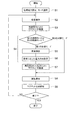
続いて、上記構成を備えるリフティングマグネット制御システムの動作を説明しつつ、本実施形態によるリフティングマグネット制御方法について説明する。図4は、本実施形態によるリフティングマグネット制御方法を示すフローチャートである。また、図5(a),(b)は、リフティングマグネット10の両端に印加される電圧(図5(a))、及びリフティングマグネット10に供給される電流(図5(b))の、それぞれ時間波形を示すグラフである。なお、上述したようにリフティングマグネット10への印加電圧はPWMによって調整されるが、図5(a)においては、PWMにおける電圧変化を時間的に平均化して得られる実効電圧の値を示している。また、図5(a),(b)における電圧及び電流の符号については、図3に示した励磁電流I1の向きを正としている。
Next, the lifting magnet control method according to the present embodiment will be described while explaining the operation of the lifting magnet control system having the above configuration. FIG. 4 is a flowchart showing a lifting magnet control method according to the present embodiment. 5A and 5B show the voltage applied to both ends of the lifting magnet 10 (FIG. 5A) and the current supplied to the lifting magnet 10 (FIG. 5B), respectively. It is a graph which shows a time waveform. As described above, the voltage applied to the lifting
本実施形態のリフティングマグネット制御方法では、図4に示すように、まず初期電力設定およびモード選択を行う(ステップS1)。このステップS1においては、リフティングマグネット10に供給する電力の大きさの初期値が、例えばリフティングマグネット10により吊下しようとする吊荷の最大荷重(所定値)に応じて設定される。ここで、表1は、図5(a)に示すオーバーシュート励磁電圧VOS、オーバーエキサイト励磁電圧VOE、定格励磁電圧VRA、および釈放電圧VREの初期設定値の一例を示す表であり、各初期設定値が吊荷の最大荷重に応じて予め定められている。この表1の内容を含むデータ、すなわち吊荷の最大荷重と励磁電圧および釈放電圧の大きさとが対応付けられたデータは、例えば入力装置4の信号処理部42(図2参照)が有する記憶手段(メモリ)に記憶されている。そして、操作者がタッチパネル41を介して吊荷の最大荷重を入力すると、その最大荷重に対応する電圧VOS、VOE、VRA、およびVREの初期設定値が当該データに基づいて選択され、設定入力情報D1(図2参照)として制御部33へ送られる。

なお、本実施形態では上述したようにリフティングマグネットへの印加電圧(励磁電圧および釈放電圧)と吊荷の最大荷重とが予め対応付けられているが、リフティングマグネットへの供給電流(励磁電流または釈放電流、或いはその両方)と吊荷の最大荷重とが予め対応付けられていてもよく、印加電圧および供給電流の双方が吊荷の最大荷重と対応付けられていてもよい。 In this embodiment, as described above, the voltage applied to the lifting magnet (excitation voltage and release voltage) and the maximum load of the suspended load are associated in advance, but the supply current to the lifting magnet (excitation current or release) Current or both) and the maximum load of the suspended load may be associated in advance, and both the applied voltage and the supply current may be associated with the maximum load of the suspended load.
また、ステップS1においては、タッチパネル41を介して第1及び第2の制御モードのいずれか一方が操作者により選択される。選択された制御モードは、信号処理部42によって認識される。
In step S1, either one of the first and second control modes is selected by the operator via the
続いて、操作者によりマグネット操作部5のスイッチ51(または52)が操作されると(ステップS2:図5に示す時刻t1)、制御部33は、リフティングマグネット10の励磁を開始する(ステップS3:初期電力供給ステップ)。すなわち、制御部33の指示を受けたブリッジドライバ32は、Hブリッジ回路部37のトランジスタ37a及び37dを導通させる。これにより、リフティングマグネット10に励磁電流I1が流れる。
Subsequently, when the switch 51 (or 52) of the magnet operation unit 5 is operated by the operator (step S2: time t 1 shown in FIG. 5), the
制御部33は、図5に示す最初の期間T1において、PWMのデューティ比を高めて励磁電圧(実効値)を最大値VOSとする。この期間T1をオーバーシュート期間(OS期間)と称し、リフティングマグネット10への励磁電流I1を短時間で立ち上げるための期間である。また、制御部33は、期間T1の次の期間T2において、PWMのデューティ比を低下させて、励磁電圧(実効値)をVOE(<VOS)とする。この期間T2をオーバーエキサイト期間(OE期間)と称し、吊荷を容易に捕捉できるようにリフティングマグネット10の磁力を一時的に高める期間である。また、制御部33は、期間T2の次の期間T3の初めにおいて、PWMのデューティ比を更に低下させて、励磁電圧(実効値)をVRA(<VOE)とする。この期間T3を定格励磁期間と称し、リフティングマグネット10の定格電力付近の電力を供給しつつ励磁状態を維持する期間である。励磁電圧VOSおよびVOEは、前述した初期電力設定ステップS1により設定された大きさ、すなわち吊荷の最大荷重に対応する大きさに制御される。また、励磁電圧VRAは、期間T3の当初において、前述した初期電力設定ステップS1により設定された大きさ、すなわち吊荷の最大荷重に対応する大きさVRA1に制御される。
続いて、リフティングマグネット制御システムは、電力制御ステップS4へ移行する。このステップS4において、信号処理部42は、ステップS1により第1の制御モードが選択された場合に、次の電力調整ステップS5,S6を実行する。まず、信号処理部42は、荷重計20から提供された信号に基づいて、そのとき吊下されている吊荷の質量を検知する(ステップS5)。そして、信号処理部42は、ステップS1において設定された最大荷重より吊荷の質量が小さい場合には、リフティングマグネット10に供給される電力が現在の吊荷の質量に対応する大きさとなるように、リフティングマグネット10への印加電圧または供給電流或いはその双方の大きさを、再び設定する(ステップS6)。
Subsequently, the lifting magnet control system proceeds to the power control step S4. In step S4, when the first control mode is selected in step S1, the
ここで、表2は、ステップS6において用いられる定格励磁電圧VRAおよび釈放電圧VREの再設定値の一例を示す表であり、各設定値が吊荷の検出質量に応じて予め定められている。この表2の内容を含むデータ、すなわち吊荷の検出質量と励磁電圧および釈放電圧の大きさとが対応付けられたデータは、例えば信号処理部42が有する記憶手段(メモリ)に記憶されている。そして、検出された吊荷の質量に対応する電圧VRAおよびVREの再設定値が当該データに基づいて選択され、設定入力情報D1(図2参照)として制御部33へ送られる。制御部33は、この設定入力情報D1に基づいて、リフティングマグネット10への定格電圧VRAおよび釈放電圧VREを吊荷の検出質量に対応する大きさ(VRA2,VRE2)に低下させる(ステップS7)。
なお、上記したステップS5により検出された吊荷の質量が最大荷重と同じか最大荷重より大きい場合、信号処理部42は、ステップS6においてリフティングマグネット10への印加電圧や供給電流を再設定することなく、初期設定された印加電圧や供給電流を維持する。
If the mass of the suspended load detected in step S5 is equal to or greater than the maximum load, the
ステップS1により第2の制御モードが選択された場合には、信号処理部42は上述したステップS5,S6を実行しない。このとき、制御部33は、リフティングマグネット10へ供給される電力を、吊荷の質量にかかわらず初期設定された大きさに維持することとなる。具体的には、図5(a)に一点鎖線で示すように、期間T3において励磁電圧VRA1を維持し、期間T4において釈放電圧VRE1を維持する。
When the second control mode is selected in step S1, the
続いて、リフティングマグネット10から鉄片等を釈放(解放)するための動作に移る。マグネット操作部5の他方のスイッチ52(または51)を操作者が押すと(ステップS8:図5に示す時刻t2)、制御部33はリフティングマグネット10の消磁を開始する。すなわち、制御部33の指示を受けたブリッジドライバ32は、Hブリッジ回路部37のトランジスタ37a及び37dを非導通とし、トランジスタ37b及び37cを導通させる。これにより、リフティングマグネット10の電流の向きが反転し、釈放電流I2が流れる(ステップS9:図5に示す期間T4)。このときの釈放電圧は、第1の制御モードにおいては吊荷の検出質量に対応する大きさVRE2(<VRE1)に設定され、第2の制御モードにおいては初期設定値VRE1に設定される。これにより、リフティングマグネット10および吊荷が消磁され、吊荷が開放される。制御部33は、釈放電流I2が流れたのち、Hブリッジ回路部37のトランジスタ37b及び37cを非導通とし、電力回生のためトランジスタ37a及び37dを一定時間だけ導通させた後(図5に示す期間T5)、全てのトランジスタ37a〜37dを非導通として電力供給を停止する。
Subsequently, the operation proceeds to release (release) the iron pieces from the lifting
以上に説明したリフティングマグネット制御システムおよびリフティングマグネット制御方法においては、リフティングマグネット10に吊荷Gが吊下された状態で、リフティングマグネット10への供給電力を吊荷Gの質量に対応する大きさまで低下させている。これにより、リフティングマグネット10の吸着力に対して吊荷Gが軽い場合にはその吸着力を必要十分な大きさまで低下させ、過剰な電力消費を抑えることができる。また、リフティングマグネット10への供給電力の大きさを吊下された吊荷Gの質量に対応させるので、特許文献1に記載された方法とは異なり吊荷Gを持ち上げるたびに吊荷の一部を落とす必要がなく、作業効率を好適に維持できる。
In the lifting magnet control system and the lifting magnet control method described above, the power supplied to the lifting
また、本実施形態のように、吊荷Gの質量と、供給電力における電流及び電圧のうち少なくとも一方の大きさとが対応付けられたデータに従って供給電力を低下させると尚良い。これによって、リフティングマグネット10への供給電力(電流または電圧、或いはその双方)の大きさをデータに従って容易に決定できる。 Further, as in the present embodiment, it is preferable to reduce the supply power according to data in which the mass of the suspended load G is associated with at least one of the current and voltage in the supply power. Thereby, the magnitude of the power supplied to the lifting magnet 10 (current and / or voltage) can be easily determined according to the data.
また、本実施形態のように、荷重計20により検出された吊荷Gの質量が所定の最大荷重より大きい場合には、供給電力の大きさを維持すると良い。これにより、吊下された吊荷Gの質量が大きい場合でも吊荷Gの一部を落下させることなく作業を安全に行うことができる。
Moreover, when the mass of the suspended load G detected by the
また、リフティングマグネット制御システムおよびリフティングマグネット制御方法は、本実施形態のように、第1の制御モード(荷重計20により検出された吊荷Gの質量が所定の最大荷重より小さい場合に供給電力を該質量に対応する大きさに低下させる)と、第2の制御モード(吊荷Gの質量にかかわらず供給電力を初期設定された大きさに維持する)とを有すると尚良い。これにより、吊荷Gの質量に応じて供給電力を低下させて消費電力を節減したり(第1の制御モード)、或いは供給電力を吊荷Gの目標質量に対応する大きさに固定して作業する(第2の制御モード)といった二つの作業方法を、場面に応じて好適に使い分けることができる。特に、第2のモードを有することによって、一度に運搬する吊荷の量を操作者自らが制限することを容易にし、作業スペースが限られた場所でも安全に作業を行うことができる。
In addition, the lifting magnet control system and the lifting magnet control method are the same as those in the first embodiment in the first control mode (when the mass of the suspended load G detected by the
本発明によるリフティングマグネット制御システムおよびリフティングマグネット制御方法は、上記した実施形態に限られるものではなく、他に様々な変形が可能である。例えば、上記実施形態ではリフティングマグネットへの供給電力を吊荷の質量に対応する大きさに低下させる第1の制御モード、および吊荷の質量にかかわらず供給電力を初期設定値に維持する第2の制御モードの双方を有しているが、本発明によるリフティングマグネット制御システムおよびリフティングマグネット制御方法は、第1の制御モードのみを有してもよい。 The lifting magnet control system and the lifting magnet control method according to the present invention are not limited to the above-described embodiments, and various other modifications are possible. For example, in the above embodiment, the first control mode in which the power supplied to the lifting magnet is reduced to a size corresponding to the mass of the suspended load, and the second that maintains the supplied power at the initial setting value regardless of the mass of the suspended load. However, the lifting magnet control system and the lifting magnet control method according to the present invention may have only the first control mode.
また、上記実施形態ではリフティングマグネットへの供給電力を設定・調整する機能を入力装置の信号処理部が有しているが、この機能は他の装置(マグネット制御装置の制御部など)が有してもよい。 In the above embodiment, the signal processing unit of the input device has a function of setting / adjusting the power supplied to the lifting magnet, but this function is provided by other devices (such as the control unit of the magnet control device). May be.
また、上記実施形態では入力装置とマグネット制御装置との通信手段として有線によるシリアル通信回路を例示したが、通信手段は無線でもよく、或いは伝達情報を電圧等で示すアナログ信号線でもよい。また、入力装置としては、上述したタッチパネル以外にも、例えば調整つまみやスイッチ、或いは各設定値を記憶したメモリカードの読み取り装置など、様々な手段を適用できる。 In the above embodiment, a wired serial communication circuit is exemplified as a communication means between the input device and the magnet control device. However, the communication means may be wireless or an analog signal line indicating transmission information in voltage or the like. In addition to the touch panel described above, various means such as an adjustment knob, a switch, or a memory card reading device storing each set value can be applied as the input device.
1…リフティングマグネット車両、2…リフティングマグネット制御システム、3…マグネット制御装置(マグネット制御盤)、4…入力装置、5…マグネット操作部、10…リフティングマグネット、12…アーム、14…運転室、20…荷重計、31…マグネット駆動回路、32…ブリッジドライバ、33…制御部、34,43…シリアル通信回路、36…直流変換部、37…ブリッジ回路部、39…電流測定部、41…タッチパネル、42…信号処理部、51,52…スイッチ、ACG…三相交流電源、G…吊荷、I1…励磁電流、I2…釈放電流。
DESCRIPTION OF
Claims (6)
前記電力の大きさを制御する制御部と、
前記リフティングマグネットに吊荷が吊下された状態で、該吊荷の質量を検出する質量検出手段と
を備え、
前記制御部は、前記質量検出手段により検出された前記吊荷の質量が所定値より小さい場合に前記電力を該質量に対応する大きさに低下させる第1の制御モードと、前記吊荷の質量にかかわらず前記電力を初期設定された大きさに維持する第2の制御モードとを有することを特徴とする、リフティングマグネット制御システム。 A magnet drive circuit for supplying power to the lifting magnet;
A control unit for controlling the magnitude of the power;
A mass detecting means for detecting a mass of the suspended load in a state where the suspended load is suspended from the lifting magnet;
Wherein the control unit includes a first control mode to decrease the size of the mass of the suspended load detected by the weight detecting means corresponds to the mass of the pre-Symbol power is smaller than a predetermined value, the suspended load A lifting magnet control system comprising: a second control mode for maintaining the power at a preset magnitude regardless of mass .
前記制御部は、前記第1の制御モードにおいて前記記憶手段の前記データに従って前記電力を低下させることを特徴とする、請求項1に記載のリフティングマグネット制御システム。 Storage means for storing data in which the mass of the suspended load is associated with at least one of the current and voltage in the electric power;
The lifting magnet control system according to claim 1, wherein the control unit reduces the power according to the data of the storage unit in the first control mode .
初期設定された大きさの前記電力を前記リフティングマグネットに供給する初期電力供給ステップと、
前記リフティングマグネットに吊荷が吸着されて吊下された状態で、該吊荷の質量が所定値より小さい場合に前記電力を該質量に対応する大きさに低下させる第1の制御モード、および前記吊荷の質量にかかわらず前記電力を初期設定された大きさに維持する第2の制御モードのうちいずれか一方を、操作者の選択に応じて実行する電力制御ステップと
を備えることを特徴とする、リフティングマグネット制御方法。 A method for controlling the amount of power supplied to a lifting magnet,
An initial power supply step of supplying the lifting magnet with the power of a preset magnitude;
A first control mode for reducing the electric power to a magnitude corresponding to the mass when the mass of the suspended load is smaller than a predetermined value in a state where the suspended load is attracted to and suspended by the lifting magnet ; and A power control step of executing any one of the second control modes for maintaining the power at a preset size regardless of the mass of the suspended load according to an operator's selection, A lifting magnet control method.
During the first control mode of the power control step, and maintains the magnitude of the power in case the mass of the suspended load is greater than the predetermined value, according to claim 4 or 5 Lifting magnet control method.
Priority Applications (1)
| Application Number | Priority Date | Filing Date | Title |
|---|---|---|---|
| JP2007162976A JP5000394B2 (en) | 2007-06-20 | 2007-06-20 | Lifting magnet control system and lifting magnet control method |
Applications Claiming Priority (1)
| Application Number | Priority Date | Filing Date | Title |
|---|---|---|---|
| JP2007162976A JP5000394B2 (en) | 2007-06-20 | 2007-06-20 | Lifting magnet control system and lifting magnet control method |
Publications (2)
| Publication Number | Publication Date |
|---|---|
| JP2009001369A JP2009001369A (en) | 2009-01-08 |
| JP5000394B2 true JP5000394B2 (en) | 2012-08-15 |
Family
ID=40318206
Family Applications (1)
| Application Number | Title | Priority Date | Filing Date |
|---|---|---|---|
| JP2007162976A Expired - Fee Related JP5000394B2 (en) | 2007-06-20 | 2007-06-20 | Lifting magnet control system and lifting magnet control method |
Country Status (1)
| Country | Link |
|---|---|
| JP (1) | JP5000394B2 (en) |
Families Citing this family (2)
| Publication number | Priority date | Publication date | Assignee | Title |
|---|---|---|---|---|
| JP6052882B2 (en) * | 2013-03-21 | 2016-12-27 | 住友建機株式会社 | Work machine |
| JP7463162B2 (en) * | 2020-03-30 | 2024-04-08 | 住友重機械工業株式会社 | Work Machine |
Family Cites Families (10)
| Publication number | Priority date | Publication date | Assignee | Title |
|---|---|---|---|---|
| JPH0544376Y2 (en) * | 1987-07-06 | 1993-11-10 | ||
| JP2757368B2 (en) * | 1988-03-25 | 1998-05-25 | 神鋼電機株式会社 | Steelmaking raw material supply device using lifting electromagnet |
| JPH0373791A (en) * | 1989-08-10 | 1991-03-28 | Nippon Steel Corp | Controller for quantity of suspended steel plate on lifting magnet type crane |
| JPH04120707A (en) * | 1990-09-12 | 1992-04-21 | Shinko Electric Co Ltd | Excitation of lifting electromagnet |
| JPH10332466A (en) * | 1997-05-30 | 1998-12-18 | Kawaden Co Ltd | Adjustment of attracting weight by lifting magnet |
| JP3934791B2 (en) * | 1998-06-09 | 2007-06-20 | 住友重機械工業株式会社 | Lifting amount adjustment control device for lifting magnet |
| JP2000203719A (en) * | 1998-11-11 | 2000-07-25 | Daido Steel Co Ltd | Scrap carrier system |
| JP2002160887A (en) * | 2000-11-27 | 2002-06-04 | Sumitomo Heavy Ind Ltd | Piling magnet device |
| JP2005247543A (en) * | 2004-03-05 | 2005-09-15 | Sumitomo (Shi) Construction Machinery Manufacturing Co Ltd | Lifting magnet control method |
| JP2006290474A (en) * | 2005-04-05 | 2006-10-26 | Sumitomo (Shi) Construction Machinery Manufacturing Co Ltd | Lifting magnet control device for construction machinery |
-
2007
- 2007-06-20 JP JP2007162976A patent/JP5000394B2/en not_active Expired - Fee Related
Also Published As
| Publication number | Publication date |
|---|---|
| JP2009001369A (en) | 2009-01-08 |
Similar Documents
| Publication | Publication Date | Title |
|---|---|---|
| CN104885357A (en) | Electric power tool | |
| US7554279B2 (en) | Method for operating an electronically commutated motor, and motor for carrying out a method such as this | |
| JP4356685B2 (en) | Power generation control device and power generation system | |
| EP2293408A2 (en) | Power control apparatus and method thereof | |
| US8004814B2 (en) | Method and apparatus for controlling a lifting magnet supplied with an AC source | |
| WO2009086171A1 (en) | Method and apparatus for controlling a lifting magnet supplied with an ac source | |
| US7992850B2 (en) | System and method for controlling electromagnet lift power for material handlers | |
| JP5000394B2 (en) | Lifting magnet control system and lifting magnet control method | |
| EP2484931A1 (en) | Device and method for controlling power-off type electromagnetic brake | |
| JP5253747B2 (en) | Lifting magnet control system | |
| JP4335198B2 (en) | Lifting magnet drive circuit | |
| JP5367229B2 (en) | Lifting magnet control system | |
| JP2007129809A (en) | Voltage controller for vehicle | |
| JP4607199B2 (en) | Lifting magnet drive circuit | |
| JP5160108B2 (en) | Lifting magnet control system | |
| JP2007161402A (en) | Lifting magnet driving circuit | |
| JP6737545B2 (en) | Lifting magnet device | |
| JP5410002B2 (en) | Lifting magnet control system | |
| JP2002170712A (en) | Portable magnetizing-demagnetizing device | |
| JP2020152472A (en) | Lifting magnet device and working vehicle | |
| KR101164816B1 (en) | Current polarity determinating apparatus and control method thereof | |
| KR20140136645A (en) | Power Supply Circuit for Lifting Magnet | |
| JP6578753B2 (en) | Magnet work machine | |
| JP2012095458A (en) | Power supply unit and power tool having the same | |
| JP2006096508A (en) | Electromagnet unit for forklift, and forklift loaded with the same |
Legal Events
| Date | Code | Title | Description |
|---|---|---|---|
| A621 | Written request for application examination |
Free format text: JAPANESE INTERMEDIATE CODE: A621 Effective date: 20090713 |
|
| A977 | Report on retrieval |
Free format text: JAPANESE INTERMEDIATE CODE: A971007 Effective date: 20111116 |
|
| A131 | Notification of reasons for refusal |
Free format text: JAPANESE INTERMEDIATE CODE: A131 Effective date: 20120221 |
|
| A521 | Written amendment |
Free format text: JAPANESE INTERMEDIATE CODE: A523 Effective date: 20120419 |
|
| TRDD | Decision of grant or rejection written | ||
| A01 | Written decision to grant a patent or to grant a registration (utility model) |
Free format text: JAPANESE INTERMEDIATE CODE: A01 Effective date: 20120515 |
|
| A01 | Written decision to grant a patent or to grant a registration (utility model) |
Free format text: JAPANESE INTERMEDIATE CODE: A01 |
|
| A61 | First payment of annual fees (during grant procedure) |
Free format text: JAPANESE INTERMEDIATE CODE: A61 Effective date: 20120516 |
|
| R150 | Certificate of patent or registration of utility model |
Free format text: JAPANESE INTERMEDIATE CODE: R150 |
|
| FPAY | Renewal fee payment (event date is renewal date of database) |
Free format text: PAYMENT UNTIL: 20150525 Year of fee payment: 3 |
|
| LAPS | Cancellation because of no payment of annual fees |