JP6737545B2 - Lifting magnet device - Google Patents
Lifting magnet device Download PDFInfo
- Publication number
- JP6737545B2 JP6737545B2 JP2016063702A JP2016063702A JP6737545B2 JP 6737545 B2 JP6737545 B2 JP 6737545B2 JP 2016063702 A JP2016063702 A JP 2016063702A JP 2016063702 A JP2016063702 A JP 2016063702A JP 6737545 B2 JP6737545 B2 JP 6737545B2
- Authority
- JP
- Japan
- Prior art keywords
- magnet
- lifting magnet
- regenerative
- current
- control device
- Prior art date
- Legal status (The legal status is an assumption and is not a legal conclusion. Google has not performed a legal analysis and makes no representation as to the accuracy of the status listed.)
- Active
Links
Images


Description
本発明は、リフティングマグネット装置に関する。さらに詳しくは、回生電力を消費するための抵抗を備えたリフティングマグネット装置に関する。 The present invention relates to a lifting magnet device. More specifically, the present invention relates to a lifting magnet device having a resistor for consuming regenerative power.
一般に、荷役作業や建設作業等において鉄片を持ち上げるためのリフティングマグネット装置が知られている。このリフティングマグネット装置はマグネットの励磁と消磁のみによって、鉄片を吸着、解放する。鉄片を吸着する際には制御装置が、電力供給装置からリフティングマグネットに向けて、吸着をするための電力を供給する。制御装置は、鉄片を解放する際には、供給された電力を回生させ磁気エネルギーをゼロにし、その後電力供給装置からリフティングマグネットに向けて鉄片を解放するための電力を供給する。そして解放後に供給された電力を、制御装置は回生するよう制御する。 BACKGROUND ART Generally, a lifting magnet device for lifting an iron piece in cargo handling work, construction work, etc. is known. This lifting magnet device attracts and releases iron pieces only by exciting and demagnetizing the magnet. When adsorbing the iron piece, the control device supplies electric power for adsorbing to the lifting magnet from the power supply device. When releasing the iron piece, the control device regenerates the supplied electric power to reduce the magnetic energy to zero, and then supplies electric power for releasing the iron piece from the power supply device to the lifting magnet. Then, the control device controls the electric power supplied after the release so that the electric power is regenerated.
上記の回生された電力は、コンデンサを用いて電荷を貯蔵する方法もあるが、抵抗を備え、この抵抗で回生された電力を消費する構成が多く採用されている(特許文献1)。すなわち、吸着を終えた後、解放のための電力を供給する前に、供給された電力を抵抗により消費して、磁気エネルギーをゼロにする。解放のための電力を供給した場合についても、供給された電力を抵抗により消費して、磁気エネルギーをゼロにしておくことが求められる。 Although there is a method of storing electric charge by using a capacitor for the regenerated electric power, a configuration in which a resistor is provided and the regenerated electric power is consumed by this resistance is often adopted (Patent Document 1). That is, after the adsorption is finished and before the electric power for releasing is supplied, the supplied electric power is consumed by the resistor to reduce the magnetic energy to zero. Even when the power for release is supplied, it is required to consume the supplied power by the resistance and keep the magnetic energy to zero.
ここで、この回生電力を消費するための回生抵抗を含む回路において、回路を開閉するトランジスタ等が故障した場合、回生抵抗に全く電流が流れなくなるか、回生抵抗に常時電流が流れるかのどちらかになる。回生抵抗に全く電流が流れない場合、別途設けられているコンデンサの電圧が上昇するので、この電圧を検出することで故障を検出することができる。しかしトランジスタ等の故障により、回生抵抗に常時電流が流れるようになった場合、トランジスタが正常に動作するのと同じように、回生抵抗に電流が流れるため、トランジスタ等の故障を検知することはできないという問題がある。しかもトランジスタ等の故障により、回生抵抗に常時電流が流れるようになると、回生抵抗での発熱量が多くなり、この発熱により、回路部品が故障するなどの問題が発生する。 Here, in a circuit including a regenerative resistor for consuming this regenerative power, if a transistor or the like that opens or closes the circuit fails, either no current flows to the regenerative resistor or a current always flows to the regenerative resistor. become. When no current flows through the regenerative resistor, the voltage of the separately provided capacitor rises, and therefore a failure can be detected by detecting this voltage. However, if a current always flows through the regenerative resistor due to a failure of the transistor, etc., the failure of the transistor cannot be detected because the current flows through the regenerative resistor, just as the transistor operates normally. There is a problem. Moreover, if a current always flows through the regenerative resistor due to a failure of the transistor or the like, the regenerative resistor generates a large amount of heat, and this heat generation causes a problem such as failure of circuit components.
本発明は上記事情に鑑み、回生抵抗に常時電流が流れる異常事態を検出することができる機能が備えられているリフティングマグネット装置を提供することを目的とする。 In view of the above circumstances, it is an object of the present invention to provide a lifting magnet device provided with a function capable of detecting an abnormal situation in which a current constantly flows through a regenerative resistor.
第1発明のリフティングマグネット装置は、供給される電力により吸着力を発生させるリフティングマグネットと、前記リフティングマグネットに電力を供給するマグネット制御部と、動作指令の入出力や異常を表示したり、異常を報知したりする表示・覚知部と、が備えられており、該マグネット制御部には、該マグネット制御部の制御を行う制御装置と、前記リフティングマグネットからの回生電力を消費する回生抵抗と、該回生抵抗の状態を検出する状態検出手段と、が備えられており、前記制御装置は、前記回生抵抗の物理量が、あらかじめ定められた物理量の閾値を超え、かつ、該閾値を超えている時間が、あらかじめ定められた時間を経過したとき異常状態と判断し、前記表示・覚知部に異常状態を前記操作者に覚知させる指令を送ることを特徴とする。
第2発明のリフティングマグネット装置は、第1発明において、前記状態検出手段は、前記回生抵抗に対応して設けられている比較器であることを特徴とする。
第3発明のリフティングマグネット装置は、第1発明または第2発明において、前記制御装置は、前記状態検出手段からの信号により異常状態と判断すると、前記マグネット制御部への電力の供給を停止することを特徴とする。
A lifting magnet device according to a first aspect of the present invention includes a lifting magnet that generates an attraction force by supplied electric power, a magnet control unit that supplies electric power to the lifting magnet, an input/output of an operation command, an abnormality, and an abnormality. A display/sensing unit for notifying is provided, and the magnet control unit includes a control device that controls the magnet control unit, and a regenerative resistor that consumes regenerative power from the lifting magnet, A state detecting means for detecting the state of the regenerative resistance is provided , and the control device has a physical quantity of the regenerative resistance exceeding a threshold of a predetermined physical quantity, and a time during which the threshold is exceeded. However, when a predetermined time has passed, it is determined that an abnormal state has occurred, and a command is sent to the display/sensing unit to notify the operator of the abnormal state .
A lifting magnet device according to a second invention is characterized in that, in the first invention, the state detecting means is a comparator provided corresponding to the regenerative resistor.
A lifting magnet device according to a third aspect of the present invention is the lifting magnet device according to the first or second aspect of the invention, wherein when the control device determines that there is an abnormal state based on a signal from the state detection means, it stops supplying power to the magnet control section. Is characterized by.
第1発明によれば、回生電流を消費する回生抵抗を備えたリフティングマグネット装置において、回生抵抗の状態を検出する状態検出手段が備えられ、制御装置が状態検出手段からの信号により、回生抵抗が含まれている回生抵抗回路に常時電圧が付加されている異常状態にある場合に、表示・覚知部に異常状態を覚知させる指令を送ることにより、回生抵抗への電流の入り切りを行う回路部品が壊れたことを操作者が知ることができる。これにより、操作者が壊れた部品を取り除き、回生抵抗の発熱による他の回路部品の破損を防止できる。
第2発明によれば、状態検出手段が、回生抵抗に対応して設けられている比較器であることにより、回生抵抗のみにかかる電圧値等を検出して異常を判断できるので、異常状態を確実に検知することができる。
第3発明によれば、制御装置は、状態検出手段からの信号により異常状態と判断すると、マグネット制御部への電力の供給を停止することにより、マグネット制御部周辺の構成を大きく変更することなく、変更のコストを抑えながら回生抵抗への電流の供給を停止することができる。
According to the first aspect of the present invention, in the lifting magnet device having the regenerative resistor that consumes the regenerative current, the state detecting means for detecting the state of the regenerative resistor is provided, and the control device receives the signal from the state detecting means to detect the regenerative resistance. A circuit that turns on and off the current to the regenerative resistor by sending a command to the display/sensing unit to notify the abnormal condition when the voltage is constantly applied to the included regenerative resistor circuit. The operator can know that the part is broken. As a result, the operator can remove the broken component and prevent the damage of other circuit components due to the heat generation of the regenerative resistor.
According to the second aspect of the present invention, since the state detecting means is the comparator provided corresponding to the regenerative resistor, it is possible to detect the voltage value applied only to the regenerative resistor and judge the abnormality. It can be reliably detected.
According to the third aspect of the invention, when the control device determines that there is an abnormal state from the signal from the state detection means, it stops the supply of electric power to the magnet control part, without making a large change in the configuration around the magnet control part. The supply of current to the regenerative resistor can be stopped while suppressing the cost of change.
<回路構成の説明>
つぎに、本発明の実施形態に係るリフティングマグネット装置2を図面に基づき説明する。なお、図面の説明において同一の要素には同一の符号を付し、重複する説明を省略する。また、以下の説明において、トランジスタとは、バイポーラ型トランジスタ及び電界効果トランジスタ(FET)の双方を含むものとする。トランジスタがFETである場合、ベースをゲート、コレクタをドレイン、エミッタをソースとそれぞれ読み替えるものとする。
<Explanation of circuit configuration>
Next, the
図2には、本実施形態に係るリフティングマグネット装置2のブロック構成図を示す。リフティングマグネット10は、建屋内に設置されている天井クレーンの吊り下げ部先端に用いられていたり、野外のクレーン(ジブクレーンや門型クレーン等)や、クローラで移動する油圧ショベルの先端に、アタッチメントとして搭載されたりする。リフティングマグネット装置2の構成は、鉄片を吸着および解放するリフティングマグネット10と、このリフティングマグネット10に電力を供給するマグネット制御部3と、マグネット制御部3の操作と情報を表示するための表示・覚知部4と、マグネット制御部3に三相交流電力を供給する交流電源部(交流商用電源や交流発電機)18とを備えている。
FIG. 2 shows a block configuration diagram of the
マグネット制御部3は、マグネット駆動回路31と、ブリッジドライバ32と、制御装置33と、通信回路34とを有している。マグネット駆動回路31には、交流電源部18から三相交流電圧VAC1〜VAC3が供給される。マグネット駆動回路31は、リフティングマグネット10に電力を供給する回路であり、リフティングマグネット10を流れる電流の向きを制御するHブリッジ回路を含んで構成されている。ブリッジドライバ32は、このHブリッジ回路を駆動する回路である。制御装置33は、マグネット10へ供給される電流及び電圧を、ブリッジドライバ32を介して制御する。
The
制御装置33は、例えば、所定のプログラムを格納したメモリと、該所定のプログラムを読み出して実行するCPUまたはロジック回路とを含むディジタル演算処理回路からなり、制御信号の入出力・表示や覚知を、通信回路34を通じて行う。通信回路34は、リフティングマグネット装置2の操作者の操作する表示・覚知部4にある通信回路43と、配線16を介して接続されており、通信回路43との間で通信を行う。なお、本実施形態では、マグネット駆動回路31、ブリッジドライバ32、制御装置33、及び通信回路34は、1つの筐体35内に収容されている。
The
表示・覚知部4は、操作者の動作指令の入出力や異常を画面に表示するための入出力・表示装置40と、異常が発生した時に操作者にこの異常を覚知させる異常報知装置41(音を発生させたり、操作レバーや椅子を振動させたり、警告灯を点灯)と、信号処理部42と、通信回路43とを有している。入出力・表示装置40は、リフティングマグネット10に供給される電流および電圧に関わる設定入力を操作者から受け付ける機能を有する。異常報知装置41は、音を発生させたり、操作レバーや椅子を振動させたり、警告灯を点灯させて操作者に異常を報知する機能を有する。信号処理部42は、通信回路43を介して受け取った信号に基づいて、画像により操作者に制御装置33等の状態を覚知させたり、操作者の入力信号に基づいて通信回路43を介して、マグネット制御部3の制御装置33に指令を与えたり、また、異常報知装置41に異常を報知する信号を発信して、操作者にリフティングマグネット装置2の異常を覚知させたりする。なお、入出力・表示装置40、信号処理部42、及び通信回路43は、1つの筐体45内に収容されている。
The display/
マグネット操作部5は、リフティングマグネット10の励磁動作および解放動作を操作者が操作するための装置であり、表示・覚知部4と共に配置されている。マグネット操作部5は、2つのスイッチ51、52を有している。スイッチ51、52の一方の端子は互いに接続されると共に、マグネット制御部3と配線53を介して接続され、マグネット制御部3内部で定電位線と接続されている。また、スイッチ51,52の他方の端子はそれぞれ配線54,55を介してマグネット制御部3の制御装置33と接続されている。
The magnet operating unit 5 is a device for an operator to operate the exciting operation and the releasing operation of the
例えば、スイッチ51を操作者が押すと配線54を介して所定電位が制御装置33へ伝わり、制御装置33は、リフティングマグネット10へ正方向電流(励磁電流)が供給されるようにブリッジドライバ32を制御する。また、スイッチ52を操作者が押すと配線55を介して所定電位が制御装置33へ伝わり、制御装置33は、リフティングマグネット10へ逆方向電流(解放電流)が供給されるようにブリッジドライバ32を制御する。或いは、制御装置33が配線54の電位のみ認識し、スイッチ51が一度押されるとリフティングマグネット10へ励磁電流が供給され、スイッチ51が再度押されるとリフティングマグネット10へ解放電流が供給されるようにしてもよい。
For example, when the operator presses the
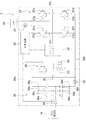
図1には、本発明の第1実施形態に係るリフティングマグネット装置2を構成するマグネット制御部3の回路構成図を示す。図1に示すように、マグネット制御部3は、制御装置33やブリッジドライバ32の他、マグネット駆動回路31を構成する直流電源部36、Hブリッジ回路部37を有し、さらにコンデンサ38、回生抵抗23、状態検出手段24、回生抵抗用スイッチ25を有する。
FIG. 1 shows a circuit configuration diagram of a
直流電源部36は、交流電源部18から供給された三相交流電圧VAC1〜VAC3を直流電源電圧VDCへ変換するための回路部分である。本実施形態の直流電源部36は、6個のダイオード36a〜36fを含むブリッジ回路によって構成されており、三相全波整流を行う。なお、直流電源部36は、これ以外にも例えばサイリスタを用いた純ブリッジ回路や、ダイオード及びサイリスタを用いた混合ブリッジ回路によって構成されてもよい。直流電源部36が純ブリッジ回路や混合ブリッジ回路によって構成される場合、サイリスタは、図示しない位相制御回路によって所定の制御角で位相制御される。
The DC
Hブリッジ回路部37は、リフティングマグネット10へ供給される電流の向きを制御するための回路部分である。Hブリッジ回路部37は、4つのnpn型のトランジスタ37a〜37dと、該4つのトランジスタ37a〜37dのそれぞれの電流端子間(コレクタ−エミッタ間またはソース−ドレイン間)に電気的に接続された4つのダイオード(フライホイール)37e〜37hと、リフティングマグネット10へ電流を供給するための動力ケーブルが接続される端子37i及び37jとを含むHブリッジ回路によって構成されている。
The H-
具体的には、トランジスタ37aの一方の電流端子は直流電源部36の正側出力端36gに電気的に接続されており、トランジスタ37aの他方の電流端子は端子37iに電気的に接続されている。直流電源部36の正側出力端36gに接続されるケーブルは、正側ライン39aと称する。トランジスタ37bの一方の電流端子は端子37iに電気的に接続されており、トランジスタ37bの他方の電流端子は直流電源部36の負側出力端36hに電気的に接続されている。直流電源部36の負側出力端に接続されるケーブルは負側ライン39bと称する。トランジスタ37cの一方の電流端子は直流電源部36の正側出力端36gに電気的に接続されており、トランジスタ37cの他方の電流端子は端子37jに電気的に接続されている。トランジスタ37dの一方の電流端子は端子37jに電気的に接続されており、トランジスタ37dの他方の電流端子は直流電源部36の負側出力端36hに電気的に接続されている。また、ダイオード37e〜37hのアノードは、それぞれトランジスタ37a〜37dの他方の電流端子に電気的に接続されており、ダイオード37e〜37hのカソードは、それぞれトランジスタ37a〜37dの一方の電流端子に電気的に接続されている。
Specifically, one current terminal of the
各トランジスタ37a〜37dの制御端子(ベースまたはゲート)はブリッジドライバ32と電気的に接続されており、各トランジスタ37a〜37dにおける電流端子間の導通状態は、ブリッジドライバ32から提供される制御電流(または制御電圧)によって制御される。例えば、トランジスタ37a及び37dの制御端子に制御電流が提供されると、ある一方向の励磁電流が、トランジスタ37a、端子37i、リフティングマグネット10、端子37j、及びトランジスタ37dの順に流れる。また、トランジスタ37b及び37cの制御端子に制御電流が提供されると、ある一方向と逆方向の消磁電流が、トランジスタ37c、端子37j、リフティングマグネット10、端子37i、及びトランジスタ37bの順に流れる。
The control terminal (base or gate) of each of the
ブリッジドライバ32は、制御装置33の出力信号に応じてトランジスタ37a〜37dの何れかを導通させる。制御装置33は、図2に示したマグネット操作部5から提供される信号に基づいて、トランジスタ37a〜37dの何れを導通させるかを決定する。また、ブリッジドライバ32は、トランジスタ37a〜37dを必要に応じて断続的に導通させ、リフティングマグネット10へ供給される電圧をパルス幅変調(PWM:Pulse Width Modulation)により調整する。このPWMのパルス幅は、制御装置33によって制御される。
The
コンデンサ38は、リフティングマグネット10への励磁電流のリップル軽減のために設けられている。コンデンサ38は、直流電源部36の正側出力端36gと負側出力端36hとの間に電気的に接続されている。
The
第1電流測定手段21は、リフティングマグネット10に供給される電流の大きさを測定する測定器で、Hブリッジ回路部37にあるHブリッジ回路とリフティングマグネット10との間に設けられている。また、第2電流測定手段22は、正側ライン39aか負側ライン39bの少なくとも一方に設けられた電流測定手段である。
The first current measuring
回生抵抗23は、リフティングマグネット10からの回生電力を消費する抵抗であり、予想される回生電力を消費するのに十分な容量を有する。回生抵抗23は、1つの抵抗器から構成される必要はなく、複数の抵抗器を並列に並べて構成することも可能である。回生抵抗23は、直流電源部36の正側出力端36gと負側出力端36hに電気的に接続されている。
The
状態検出手段24は、回生抵抗23の状態を検出するための装置である。本実施形態において、状態検出手段24は、回生抵抗23の両端の電圧を検出し、あらかじめ与えられている電圧値よりも高い電圧値を検出した時に、信号を発信する比較器である。発信された信号は、制御装置33により受信される。
The state detection means 24 is a device for detecting the state of the
回生抵抗用スイッチ25は、制御装置33の指令により、リフティングマグネット10に供給された電力の回生が可能となるように、規定されたタイミングで入り切りされる。
The
ブレーカ26は、交流電源部18と直流電源部36との接続を遮断する装置で、交流電源部18と直流電源部36との間に設けられている。
The
<通常時のマグネット駆動回路31の動作>
ここで、通常運転時のマグネット駆動回路31の動作について説明する。図3(A)は、リフティングマグネット10の両端に印加される電圧の時間波形を示すグラフを表わし、図3(B)はリフティングマグネット10に供給される電流の時間波形を示すグラフである。図3(B)は第1電流検出器21で測定した結果である。なお、上述したようにリフティングマグネット10への印加電圧はPWMによって調整されるが、図3(A)においては、PWMにおける電圧変化を時間的に平均化して得られる実効電圧の値を示している。また、図3(A),(B)における電圧及び電流の符号については、図2での励磁電流の向き(端子37iからリフティングマグネット10へ電流が流れる向き)を正としている。
<Operation of
Here, the operation of the
まず、ある時刻t0において、交流電源部18から直流電源部36に三相交流電圧VAC1〜VAC3が提供される。三相交流電圧VAC1〜VAC3は、直流電源部36によって直流電源電圧VDCに変換される。続いて、マグネット操作部5のスイッチ51(または52)を操作者が押すと(時刻t1)、制御装置33はリフティングマグネット10の励磁を開始する。すなわち、制御装置33の指示を受けたブリッジドライバ32は、Hブリッジ回路部37のトランジスタ37a及び37dを導通させる。これにより、リフティングマグネット10に励磁電流が流れる。
First, at a certain time t0, the AC
制御装置33は、最初の期間T1において、PWMのデューティ比を最大の100%として励磁電圧(実効値)を最大値VOSとする。この期間T1をオーバーシュート期間(OS期間)と称し、リフティングマグネット10への励磁電流I1を短時間で立ち上げるための期間である。また、制御装置33は、期間T1の次の期間T2において、PWMのデューティ比を最大より低下させて(例えば90%)、励磁電圧(実効値)をVOE(<VOS)とする。この期間T2をオーバーエキサイト期間(OE期間)と称し、吊荷を容易に捕捉できるようにリフティングマグネット10の磁力を一時的に高める期間である。また、制御装置33は、期間T2の次の期間T3において、PWMのデューティ比を更に低下させて、励磁電圧(実効値)をVRA(<VOE)とする。この期間T3を定格励磁期間と称し、リフティングマグネット10の定格電力付近の電力を供給しつつ励磁状態を維持する期間である。なお、定格励磁期間T3は、次の解放動作へ移行するまで継続される。
The
このような励磁電力をリフティングマグネット10へ供給することにより、リフティングマグネット10が励磁され、鉄片等の吊荷を吸着して持ち上げることが可能となる。
By supplying such exciting power to the lifting
続いて、リフティングマグネット10から鉄片等を解放するための動作に移る。マグネット操作部5の他方のスイッチ52(または51)を操作者が押すと(時刻t2)、制御装置33はリフティングマグネット10の消磁を開始する。すなわち、まず制御装置33は、Hブリッジ回路部37を構成するすべてのトランジスタ37a〜37dを非導通とするとともに、回生抵抗用スイッチ25を導通させ、リフティングマグネット10に残存する電力を、回生抵抗23で消費する。この回生抵抗23で消費される電力は図3の消費電力K1で表されている部分である。そして、次に制御装置33の指示を受けたブリッジドライバ32は、Hブリッジ回路部37のトランジスタ37a、37dおよび回生抵抗用スイッチ25を非導通とし、トランジスタ37b及び37cを導通させる。これにより、リフティングマグネット10に流れる電流の向きが反転し、解放電流が流れる(期間T4)。この解放電流は、リフティングマグネット10のインダクタンスの影響からある時定数でもって所定値に近づく。これにより、リフティングマグネット10および吊荷が消磁され、吊荷が開放される。
Then, the operation for releasing the iron piece or the like from the lifting
制御装置33は、解放電流の大きさが設定値ILMに達すると、Hブリッジ回路部37の全てのトランジスタ37a〜37dを非導通とし、回生抵抗用スイッチ25を一定時間だけ導通させ、リフティングマグネット10に残存する電力を、回生抵抗23で消費する。この回生抵抗23で消費される電力は、図3の消費電力K2で表されている部分である。そして、回生電力を消費した後(期間T5)、回生抵抗用スイッチ25を、Hブリッジ回路部37を構成するトランジスタ37a〜37dと同様、非導通として電力供給を停止する。
When the magnitude of the release current reaches the set value I LM , the
<異常時のマグネット駆動回路31の動作>
次に、異常時のマグネット駆動回路31の動作について説明する。ここでいう「異常時」とは、回生抵抗用スイッチ25が破損し、回生抵抗が含まれている回生抵抗回路に、常時電圧が付加されている異常状態が発生しているときをいう。
<Operation of the
Next, the operation of the
比較器である状態検出手段24は、回生抵抗に付加されている電圧が、あらかじめ定められた電圧値を越えている場合に、制御装置33に信号を送信する。制御装置33は、状態検出手段24からの信号が、あらかじめ定められた時間を経過したとき、回生抵抗回路に常時電圧が付加されている異常状態であると判断する。通常時の運転においても、回生抵抗23には電圧が付加されるが、通常時は、回生電力を消費するための電圧の付加であるので、その消費のための時間は比較的短い。そのため、制御装置33は、通常時に回生電力を消費するための時間よりも長い時間を、あらかじめ入力しておき、この入力値に基づいて制御装置33は、回生抵抗回路に常時電圧が付加されている異常状態であるか否かを判断する。
The state detection means 24, which is a comparator, sends a signal to the
そして、制御装置33は、回生抵抗回路が異常状態にある場合、この異常状態であることを操作者に覚知させる。覚知させる手段は様々なものがあるが、本実施形態では、表示・覚知部4に設けられている異常報知装置41から、例えば、警報を発したり、入出力・表示装置40に異常のメッセージを表示したりすることで、操作者に覚知させている。加えて、本実施形態では、制御装置33が、回生抵抗回路が異常状態にある場合、交流電源部18と直流電源部36との間に設けられているブレーカ26により、交流電源部18からの電力を遮断する。なおこの遮断動作は、制御装置33が、回生抵抗回路が異常状態にあると判断した後、リフティングマグネット10が被搬送物を吊り上げているか否かなど、リフティングマグネット10周辺の安全を考慮して行われる。
Then, when the regenerative resistance circuit is in the abnormal state, the
回生電力を消費する回生抵抗23を備えたリフティングマグネット装置2において、回生抵抗23の状態を検出する状態検出手段24が備えられ、制御装置33が状態検出手段24からの信号により、回生抵抗23が含まれている回生抵抗回路に常時電圧が付加されている異常状態にあるかどうかを判断し、操作者に覚知させることにより、回生抵抗23への電流の入り切りを行う回路部品が壊れたことを操作者が知ることができる。これにより、操作者が壊れた部品を取り除き、回生抵抗23の発熱による他の回路部品の破損を防止できる。
In the
状態検出手段24が、回生抵抗23に対応して設けられている比較器であることにより、回生抵抗23のみにかかる電圧値等を検出して異常を判断できるので、異常状態を確実に検知することができる。
Since the state detecting means 24 is a comparator provided corresponding to the
制御装置33が、回生抵抗23に付加されている電圧が、所定の電圧値を越え、かつ、その超えている時間が、所定の時間を経過した時異常状態と判断することにより、温度など、異常検知までに時間を要するパラメータと比較して、短時間で異常を検出することができる。
When the
制御装置33は、状態検出手段24からの信号により異常状態と判断すると、マグネット制御部3への電力の供給を停止することにより、マグネット制御部3周辺の構成を大きく変更することなく、変更のコストを抑えながら回生抵抗23への電流の供給を停止することができる。
When the
なお、本実施形態では、状態検出手段24として電圧を測定する比較器を採用したがこれに限定されない。例えば、回生抵抗23に付加する電圧値を検出する電圧計や、回生抵抗23に流れる電流を測定する電流計、または回生抵抗23の温度を測定する温度計を用いることもできる。また状態検出手段24が、このような物理量を検出し、それに対応した信号を送信するだけの機器の場合、制御装置33が、物理量の閾値を超えたか否かを判断するとともに、その超えたときの時間が所定の時間を超えているか否かで、回生抵抗回路が異常状態であるか否かを判断する。
In the present embodiment, the comparator for measuring the voltage is used as the state detecting means 24, but the present invention is not limited to this. For example, a voltmeter that detects the voltage value applied to the
状態検出手段24からの信号を受ける専用制御装置を設けることもできる。この場合、この専用制御装置は制御装置33の一部を構成することとなる。
It is also possible to provide a dedicated control device for receiving a signal from the
状態検出手段24は、従来からマグネット制御部3に設けられている、例えば第2電流検出器22を用いることも可能である。この場合、回生抵抗23に常時電圧が付加される異常状態となると、通常の運転時の電流よりも大きな電流が第2電流検出器22により検出されることとなる。この通常の運転時の電流よりも大きな電流が流れた時間が、所定の時間を超えると、制御装置33は回生抵抗回路が異常状態にあると判断する。または、吸引電圧を付加する信号を出していない場合に、第2電流検出器22にあらかじめ定められた電流値以上の電流が流れていることで回生抵抗回路が異常状態にあると判断することも可能である。
As the state detecting means 24, it is possible to use, for example, the second
本実施形態では、回生抵抗回路が異常状態となると、交流電源部18と直流電源部36との間に設けられているブレーカ26により、交流電源部18からの電力を遮断するようにしたが、マグネット制御部への電力の供給を停止する方法はこれに限定されない。たとえば、直流電源部36がサイリスタである場合は、この部分の動作を停止させることで遮断することも可能である。また、直流電源部36から回生抵抗回路までに設けられた直流を切り離すデバイス素子の動作を停止させることで遮断することも可能である。
In the present embodiment, when the regenerative resistance circuit is in an abnormal state, the
3 マグネット制御部
4 表示・覚知部
10 リフティングマグネット
23 回生抵抗
24 状態検出手段
33 制御装置
3
Claims (3)
前記リフティングマグネットに電力を供給するマグネット制御部と、
動作指令の入出力や異常を表示したり、異常を報知したりする表示・覚知部と、が備えられており、
該マグネット制御部には、
該マグネット制御部の制御を行う制御装置と、
前記リフティングマグネットからの回生電力を消費する回生抵抗と、
該回生抵抗の状態を検出する状態検出手段と、
が備えられており、
前記制御装置は、
前記回生抵抗の物理量が、あらかじめ定められた物理量の閾値を超え、
かつ、該閾値を超えている時間が、あらかじめ定められた時間を経過したとき異常状態と判断し、
前記表示・覚知部に異常状態を覚知させる指令を送る、
ことを特徴とするリフティングマグネット装置。 A lifting magnet that generates an attractive force by the supplied power,
A magnet control unit for supplying electric power to the lifting magnet,
It is equipped with a display/sensing unit that displays input/output of operation commands and abnormalities, and notifies of abnormalities,
The magnet control unit has
A controller for controlling the magnet controller,
A regenerative resistor that consumes regenerative power from the lifting magnet,
State detecting means for detecting the state of the regenerative resistor,
Is provided ,
The control device is
The physical quantity of the regenerative resistance exceeds a threshold of a predetermined physical quantity,
And, when the time exceeding the threshold value exceeds a predetermined time, it is determined as an abnormal state,
Sending a command to the display/sensing unit to sense an abnormal condition,
Lifting magnet device characterized in that.
ことを特徴とする請求項1に記載のリフティングマグネット装置。The lifting magnet device according to claim 1, wherein:
前記状態検出手段からの信号により異常状態と判断すると、
前記マグネット制御部への電力の供給を停止する、
ことを特徴とする請求項1または2に記載のリフティングマグネット装置。 The control device is
When it is determined that the state is abnormal by the signal from the state detecting means,
Stopping the supply of power to the magnet control unit,
The lifting magnet device according to claim 1 or 2 , wherein.
Priority Applications (1)
| Application Number | Priority Date | Filing Date | Title |
|---|---|---|---|
| JP2016063702A JP6737545B2 (en) | 2016-03-28 | 2016-03-28 | Lifting magnet device |
Applications Claiming Priority (1)
| Application Number | Priority Date | Filing Date | Title |
|---|---|---|---|
| JP2016063702A JP6737545B2 (en) | 2016-03-28 | 2016-03-28 | Lifting magnet device |
Publications (3)
| Publication Number | Publication Date |
|---|---|
| JP2017178473A JP2017178473A (en) | 2017-10-05 |
| JP2017178473A5 JP2017178473A5 (en) | 2018-06-14 |
| JP6737545B2 true JP6737545B2 (en) | 2020-08-12 |
Family
ID=60009237
Family Applications (1)
| Application Number | Title | Priority Date | Filing Date |
|---|---|---|---|
| JP2016063702A Active JP6737545B2 (en) | 2016-03-28 | 2016-03-28 | Lifting magnet device |
Country Status (1)
| Country | Link |
|---|---|
| JP (1) | JP6737545B2 (en) |
Family Cites Families (9)
| Publication number | Priority date | Publication date | Assignee | Title |
|---|---|---|---|---|
| JP2588385B2 (en) * | 1985-03-18 | 1997-03-05 | 三菱電機株式会社 | Regenerative energy-discharge circuit of motor |
| JP3473188B2 (en) * | 1995-06-21 | 2003-12-02 | 松下電器産業株式会社 | Inverter device |
| JP2006262616A (en) * | 2005-03-17 | 2006-09-28 | Meidensha Corp | Inverter device |
| JP4335198B2 (en) * | 2005-10-27 | 2009-09-30 | 住友重機械工業株式会社 | Lifting magnet drive circuit |
| JP5410002B2 (en) * | 2007-03-07 | 2014-02-05 | 住友重機械工業株式会社 | Lifting magnet control system |
| JP5253747B2 (en) * | 2007-03-12 | 2013-07-31 | 住友重機械工業株式会社 | Lifting magnet control system |
| JP5241367B2 (en) * | 2008-07-30 | 2013-07-17 | 株式会社日立産機システム | Electric hoist |
| JP2013192392A (en) * | 2012-03-14 | 2013-09-26 | Fuji Electric Co Ltd | Inverter device |
| US9013123B2 (en) * | 2013-04-22 | 2015-04-21 | Rockwell Automation Technologies, Inc. | Self protected dynamic braking |
-
2016
- 2016-03-28 JP JP2016063702A patent/JP6737545B2/en active Active
Also Published As
| Publication number | Publication date |
|---|---|
| JP2017178473A (en) | 2017-10-05 |
Similar Documents
| Publication | Publication Date | Title |
|---|---|---|
| JP2009289671A (en) | Relay control device | |
| JP5253747B2 (en) | Lifting magnet control system | |
| KR20140122179A (en) | Motor Controller | |
| JP2011120366A (en) | Overvoltage protection device | |
| JP2009011042A (en) | Method for protecting rush current prevention circuits, and inverter device | |
| US20210184457A1 (en) | Motor control apparatus including protection mechanism | |
| JP2007129809A (en) | Voltage controller for vehicle | |
| EP2028756A1 (en) | An Inverter With Short Circuit Protection | |
| JP5107167B2 (en) | Hybrid work machine | |
| JP6737545B2 (en) | Lifting magnet device | |
| JP2020058209A (en) | Motor drive device | |
| JPH0268570A (en) | Power unit for image recording device | |
| JP2007308231A (en) | Inverter device for elevators and method of controlling brake of inverter device | |
| JP2007074791A (en) | Driving unit for motor | |
| JP4185619B2 (en) | Torque monitoring method for inverter control motor in crane | |
| JP5000394B2 (en) | Lifting magnet control system and lifting magnet control method | |
| JP5978820B2 (en) | Inverter control device | |
| JP2023511516A (en) | Motor control system and motor control device | |
| JP5458542B2 (en) | Lifting magnet booster control device | |
| JP4367341B2 (en) | Dynamic brake circuit protection device | |
| JPWO2016084170A1 (en) | Motor control device and control method | |
| KR101315072B1 (en) | Lifting magnetic control apparatus for power failure and detect circuit | |
| TWI794894B (en) | Motor control apparatus and method of controlling the same | |
| KR20190007601A (en) | Electric vehicle charging protection circuit | |
| US20200328699A1 (en) | Protection device |
Legal Events
| Date | Code | Title | Description |
|---|---|---|---|
| A521 | Written amendment |
Free format text: JAPANESE INTERMEDIATE CODE: A523 Effective date: 20180423 |
|
| A621 | Written request for application examination |
Free format text: JAPANESE INTERMEDIATE CODE: A621 Effective date: 20180423 |
|
| A977 | Report on retrieval |
Free format text: JAPANESE INTERMEDIATE CODE: A971007 Effective date: 20190307 |
|
| A131 | Notification of reasons for refusal |
Free format text: JAPANESE INTERMEDIATE CODE: A131 Effective date: 20190402 |
|
| A521 | Written amendment |
Free format text: JAPANESE INTERMEDIATE CODE: A523 Effective date: 20190528 |
|
| A131 | Notification of reasons for refusal |
Free format text: JAPANESE INTERMEDIATE CODE: A131 Effective date: 20191112 |
|
| A521 | Written amendment |
Free format text: JAPANESE INTERMEDIATE CODE: A523 Effective date: 20200109 |
|
| TRDD | Decision of grant or rejection written | ||
| A01 | Written decision to grant a patent or to grant a registration (utility model) |
Free format text: JAPANESE INTERMEDIATE CODE: A01 Effective date: 20200715 |
|
| A61 | First payment of annual fees (during grant procedure) |
Free format text: JAPANESE INTERMEDIATE CODE: A61 Effective date: 20200715 |
|
| R150 | Certificate of patent or registration of utility model |
Ref document number: 6737545 Country of ref document: JP Free format text: JAPANESE INTERMEDIATE CODE: R150 |