JP4999552B2 - Sample filling jig to rotor for solid state NMR measurement - Google Patents
Sample filling jig to rotor for solid state NMR measurement Download PDFInfo
- Publication number
- JP4999552B2 JP4999552B2 JP2007142213A JP2007142213A JP4999552B2 JP 4999552 B2 JP4999552 B2 JP 4999552B2 JP 2007142213 A JP2007142213 A JP 2007142213A JP 2007142213 A JP2007142213 A JP 2007142213A JP 4999552 B2 JP4999552 B2 JP 4999552B2
- Authority
- JP
- Japan
- Prior art keywords
- rotor
- sample
- rod
- push rod
- fitting hole
- Prior art date
- Legal status (The legal status is an assumption and is not a legal conclusion. Google has not performed a legal analysis and makes no representation as to the accuracy of the status listed.)
- Expired - Fee Related
Links
Images


Landscapes
- Investigating Strength Of Materials By Application Of Mechanical Stress (AREA)
Description
本発明は、固体NMR測定用ロータへの試料充填治具に関し、詳しくは、試料の固体NMR測定を行うためにロータに供給されている試料を高い圧力で均一に圧縮して充填する治具に関するものである。 The present invention relates to a sample filling jig for a solid NMR measurement rotor, and more particularly to a jig for uniformly compressing and filling a sample supplied to a rotor with high pressure in order to perform solid NMR measurement of a sample. Is.
近年、試料の分子構造や分子運動性等を解析するために、シグナルピークが鮮明なNMRスペクトルを検出するNMR測定が行われている。一方、固体状態の試料の固体NMRスペクトルは、試料の化学シフト異方性や双極子相互作用によりスペクトルの線幅が極端に広くなり、測定分子の各部位のシグナルピークが分離できないために分子構造の解析が難しいという問題があった。これに対しては、試料管を静磁場B0の方向から所定角度(54.7°)傾けて、数kHz以上で高速回転させるマジック角回転(MAS)により、異方的な相互作用を取り除き、ピークがシャープな高分解能NMRスペクトルが得られることが知られている。例えば、特開2004−325189号公報(特許文献1)において、硫黄加硫された天然ゴムの固体高分解能13CNMRスペクトルを得るために、試料管を外部磁場に対して約54度傾けた状態で2〜5kHzで高速回転することが提案されている。 In recent years, in order to analyze the molecular structure and molecular mobility of a sample, an NMR measurement for detecting an NMR spectrum with a clear signal peak has been performed. On the other hand, the solid NMR spectrum of a solid sample has an extremely wide spectrum line width due to the chemical shift anisotropy and dipole interaction of the sample, and the signal peak at each site of the measured molecule cannot be separated. There was a problem that the analysis of was difficult. For this, the sample tube is tilted at a predetermined angle (54.7 °) from the direction of the static magnetic field B0, and the anisotropic interaction is removed by magic angle rotation (MAS) that rotates at a high speed of several kHz or more, It is known that high-resolution NMR spectra with sharp peaks can be obtained. For example, in Japanese Patent Application Laid-Open No. 2004-325189 (Patent Document 1), in order to obtain a solid high-resolution 13C NMR spectrum of sulfur-vulcanized natural rubber, the sample tube is tilted about 54 degrees with respect to an external magnetic field. It has been proposed to rotate at a high speed of ˜5 kHz.
前記マジック角回転(MAS)においては、まず、図4に示すような、試料供給口1aを有した管状容器からなるロータ1に固体試料2を充填し、羽根部が形成されたキャップ3をロータ1の試料供給口1aに圧入する。続いて、前記ロータ1をマジック角回転用プローブ(図示せず)内に配置し、ロータ1の周囲を取り囲んで配置されているステータ(図示せず)のノズルから噴出した気体ジェットを前記キャップ2の羽根部に作用させてロータ1を高速回転させることにより、前記マジック角回転(MAS)が可能となる。
In the magic angle rotation (MAS), first, a
前記マジック角回転(MAS)において、回転時にロータ1がバランスを崩すことなく安定した高速回転するためには、試料2が均一に圧縮された状態でロータ1内に高密度で充填されていることが重要である。そこで、従来においては、例えば、図5に示すような手詰め用の押し込み棒4を、ロータ1内に試料供給口1aより挿入し、ロータ1内に供給されている試料2の上方より作業者が手の力で前記押し込み棒4を押し込んで試料2を圧縮する方法が採られている[図6参照]。
In the magic angle rotation (MAS), in order for the
しかし、前記のような手詰めによる圧縮の場合、押し込み棒4による押し込み圧力が弱く、ロータ1内の試料2が均一に圧縮されにくいという問題がある。即ち、ロータ1内に試料2が不均一な状態で充填されていると、ロータ1の回転時にバランスを崩しロータ1が高速回転できなかったり、回転時の遠心力によってロータ1内に充填されている試料2全体の外形がすり鉢状に変形して(図7参照)、ロータ1の回転が安定しなかったりして、結果的にシャープなシグナルピークを有する固体高分解能NMRスペクトルが得られにくいという問題がある。また、ロータ1内に試料2が不均一な状態で充填されると、ロータ1内に充填できる試料量が少なくなり、NMR感度が低下しやすいという問題もある。
However, in the case of compression by hand packing as described above, there is a problem that the pressing pressure by the
本発明は前記問題に鑑みてなされたものであり、固体NMR測定を行うためにロータ内に供給されている試料を高い圧力で均一に圧縮できる治具を提供することを課題としている。 This invention is made | formed in view of the said problem, and makes it the subject to provide the jig | tool which can compress the sample currently supplied in the rotor uniformly with a high pressure in order to perform solid state NMR measurement.
前記課題を解決するため、試料の固体NMR測定用の管状容器からなるロータに前記試料を充填する試料充填治具であって、
セット治具本体、押し込み棒およびネジ棒を備え、
前記セット治具本体は、基台部と、該基台部の一側面から立設された支柱部と、該支柱部の上端に固定すると共に前記基台部と対向させて配置する軸受部を備え、前記基台部に前記ロータの下部を挿入する嵌合孔を設けると共に、前記軸受部に前記嵌合孔と同一軸心位置にネジ孔を備え、該ネジ孔を前記嵌合孔に嵌合固定されたロータの試料供給口と対向位置に設け、
前記押し込み棒は前記ロータの試料供給口から内部に挿入すると共に挿入状態で試料供給口から突出するものであり、
前記ネジ棒は上側部に回転操作用の把持部を両側に突設しており、
前記セット治具本体の嵌合孔に前記試料を供給したロータの下部を挿入して、該ロータを垂直方向に立設保持し、該ロータの上端開口の試料供給口に前記押し込み棒を挿入し、前記ネジ孔に上方より前記ネジ棒を回転しながら挿入して前記押し込み棒の上端に当接させて、該押し込み棒を前記ロータ内部に押し込み、該押し込み棒でロータ内に供給されている前記試料を圧縮することを特徴とする固体NMR測定用ロータへの試料充填治具を提供している。
In order to solve the above problems, a sample filling jig for filling the sample into a rotor composed of a tubular container for solid state NMR measurement of a sample,
It is equipped with a set jig body, push rod and screw rod,
The set jig body includes a base part, a support part standing from one side of the base part, and a bearing part that is fixed to the upper end of the support part and is disposed to face the base part. A fitting hole for inserting the lower portion of the rotor is provided in the base part, and a screw hole is provided at the same axial center position as the fitting hole in the bearing part, and the screw hole is fitted into the fitting hole. provided if a fixed sample supply port of the rotor and the pair oriented position,
The push rod is inserted into the rotor from the sample supply port and protrudes from the sample supply port in the inserted state .
The screw rod has a gripping part for rotation operation on the upper side and protrudes on both sides,
Insert the lower part of the rotor to which the sample has been supplied into the fitting hole of the set jig body, hold the rotor upright in the vertical direction, and insert the push rod into the sample supply port at the upper end opening of the rotor. The screw rod is inserted into the screw hole while rotating from above and brought into contact with the upper end of the push rod , and the push rod is pushed into the rotor, and the push rod is fed into the rotor. A sample filling jig for a solid-state NMR measurement rotor characterized by compressing a sample is provided.
前記のように、ネジ棒を回転させながらネジ孔に通し、該ネジ棒の先端をロータ内に挿入された押し込み棒に当接させるようにしているため、ネジ棒の回転力(締め付けトルク)によって、押し込み棒を高い圧力でロータ内部に押し込むことができる。即ち、ネジ棒を回転させ、そのトルクを利用して押し込み棒を押し込む方が、従来のような手の力による押し込み棒の押し込みに比べてはるかに大きな力で押し込むことができる。これにより前記ネジ棒によって押し込まれる押し込み棒は、ロータ内の試料を高い圧力で均一に圧縮することができ、よって、ロータを安定状態で高速回転させることが可能となる。また、ロータ内に試料を高密度で充填することができるため、ロータ内に充填できる試料量を従来の手詰めのときの1.5倍程度にまで増大させることができ、NMR感度を高めることができる。 As described above, the screw rod is passed through the screw hole while rotating, and the tip of the screw rod is brought into contact with the pushing rod inserted into the rotor, so that the rotational force (tightening torque) of the screw rod is used. The push rod can be pushed into the rotor with high pressure. That is, when the screw rod is rotated and the push-in rod is pushed in using the torque, the push-in rod can be pushed in with a much larger force than in the conventional push-in rod push-in. As a result, the push-in rod pushed in by the screw rod can uniformly compress the sample in the rotor with a high pressure, and thus the rotor can be rotated at a high speed in a stable state. In addition, since the sample can be filled in the rotor at a high density, the amount of sample that can be filled in the rotor can be increased to about 1.5 times that of conventional hand packing, and the NMR sensitivity can be increased. it can.
前記のように、セット治具本体にはロータを嵌合固定すると共に、該固定されたロータの試料供給口との対向位置に前記ネジ孔を設けているため、前記ネジ孔に通したネジ棒の進行方向に、前記試料供給口よりロータ内に挿入した押し込み棒を位置させることができる。よって、前記ネジ棒の進行により、ネジ棒の先端を前記押し込み棒に確実に当接させることができる。 As described above, since the provided the threaded hole of the rotor to the setting jig body position facing the fitting fixed to Rutotomoni, solid constant has been sample-supplying port of the rotor and passed through the screw hole A push rod inserted into the rotor from the sample supply port can be positioned in the direction of travel of the screw rod. Therefore, the tip of the screw rod can be reliably brought into contact with the push-in rod by the progress of the screw rod.
前記ロータに充填する試料は、粉末状や細片状の有機化合物が好ましいが、特に限定されない。前記ゴム材料としては、例えば、天然ゴム(NR)、スチレンブタジエンゴム(SBR)、ブタジエンゴム(BR)、イソプレンゴム(IR)、ニトリルゴム(NBR)、クロロプレンゴム(CR)等の各種ゴムやこれら2種以上のゴムをブレンドしたもの等が挙げられる。 The sample filled in the rotor is preferably an organic compound in the form of powder or strips, but is not particularly limited. Examples of the rubber material include various rubbers such as natural rubber (NR), styrene butadiene rubber (SBR), butadiene rubber (BR), isoprene rubber (IR), nitrile rubber (NBR), chloroprene rubber (CR), and the like. The thing etc. which blended 2 or more types of rubbers are mentioned.
本発明の試料充填治具は、前記のように、セット治具本体は基台部と、該基台部の一側面から立設された支柱部と、該支柱部の上端に固定すると共に前記基台部と対向させて配置する軸受部を備え、
前記基台部に前記ロータの下部を挿入する嵌合孔を有すると共に、前記軸受部に前記嵌合孔と同一軸心位置に前記ネジ孔を備え、
前記ネジ棒は上側部に回転操作用の把持部を両側に突設しており、
前記セット治具本体の嵌合孔に前記試料を供給したロータの下部を挿入して、該ロータを垂直方向に立設保持し、該ロータの上端開口の試料供給口に前記押し込み棒を挿入し、前記ネジ孔に上方より前記ネジ棒を回転しながら挿入して前記押し込み棒の上端に当接させて押し込む構成としている。
Specimenstuffing jig of the present invention, the As described above, the set jig body base portion, and a support portion which is erected from one side of the base stand part, is fixed to the upper end of said supporting column portion Provided with a bearing portion arranged to face the base portion,
While having a fitting hole for inserting the lower part of the rotor in the base part, the bearing part is provided with the screw hole at the same axial center position as the fitting hole,
The screw rod has a gripping part for rotation operation on the upper side and protrudes on both sides,
Insert the lower part of the rotor to which the sample has been supplied into the fitting hole of the set jig body, hold the rotor upright in the vertical direction, and insert the push rod into the sample supply port at the upper end opening of the rotor. , it is set to write no configuration press inserted while rotating the threaded rod from above is brought into contact with the upper end of the push rod into the screw hole.
前記構成によれば、セット治具本体を構成する基台部にロータの下部を挿入する嵌合孔を設けると共に、基台部に対面配置される軸受部の前記嵌合孔と同一軸心位置に、前記ネジ孔を設けているため、前記嵌合孔にロータの下部を挿入し垂直方向に立設保持したロータの上端開口に挿入した押し込み棒を、前記ネジ孔に通したネジ棒が垂直方向に押圧することができる。したがって、前記ネジ棒によって押し込まれる押し込み棒は、ロータに供給された試料を垂直方向に均一に圧縮することができ、より安定したロータの高速回転が可能となる。 According to the said structure, while providing the fitting hole which inserts the lower part of a rotor in the base part which comprises a setting jig main body, the same axial center position as the said fitting hole of the bearing part arrange | positioned facing a base part Since the screw hole is provided, the lower part of the rotor is inserted into the fitting hole, and the push rod inserted into the upper end opening of the rotor that is vertically held is inserted into the screw hole. Can be pressed in the direction. Therefore, the push-in rod pushed by the screw rod can uniformly compress the sample supplied to the rotor in the vertical direction, and more stable high-speed rotation of the rotor is possible.
また、前記のように、ネジ棒の上側部に回転操作用の把持部を両側に突設させることにより、ネジ棒の回転操作を容易にし、把持部に加える力が小さくても大きなトルクを得て、高い圧力で押し込み棒をロータ内部に押し込むことができる。
なお、両側に突出させる前記把持部の長さは限定されないが、使い易さの点から5〜10cm程度が好ましい。
In addition, as described above, the gripping portion for the rotation operation is provided on both sides of the upper portion of the screw rod so that the screw rod can be easily rotated, and a large torque can be obtained even if the force applied to the gripping portion is small. Thus, the push rod can be pushed into the rotor with high pressure.
In addition, although the length of the said holding part made to protrude on both sides is not limited, About 5-10 cm is preferable from the point of ease of use.
また、前記押し込み棒の上端面には、当接させるネジ棒先端の形状に合わせた凹部を設けておくことが好ましい。これにより、ネジ棒と押し込み棒との接触面積を大きくし、押し込み棒に大きな力を負荷することができると共に、安定状態で押し込み棒をロータ内部に押し込んでいくことができる。 Moreover, it is preferable to provide the recessed part according to the shape of the front-end | tip of the screw rod to contact | abut on the upper end surface of the said pushing rod. As a result, the contact area between the screw rod and the push rod can be increased, a large force can be applied to the push rod, and the push rod can be pushed into the rotor in a stable state.
前記ロータは外径が3〜10mmφの円筒管からなり、
前記押し込み棒は前記ロータの内径に対して−0.01〜−0.5mmの外径を有すると共にロータの長さ以上の長さを有する円柱棒からなることが好ましい。
The rotor comprises a cylindrical tube having an outer diameter of 3 to 10 mmφ,
The push-in rod is preferably a cylindrical rod having an outer diameter of -0.01 to -0.5 mm with respect to the inner diameter of the rotor and a length equal to or longer than the length of the rotor.
前記のように、押し込み棒を、ロータの内径に対して−0.01〜−0.5mmの外径を有する円柱棒とすることが好ましいのは、前記押し込み棒の外径が(ロータの内径−0.01mm)より大きい場合には、押し込み棒をロータ内にスムーズに押し込むことができなくなるおそれがある一方、押し込み棒の外径が(ロータの内径−0.5mm)より小さい場合には、ロータ内に供給されている試料全体を均一に圧縮できなくなるおそれがあるためである。
また、押し込み棒の長さをロータの長さ以上とすることにより、押し込み棒のロータ内への押し込みならびに試料圧縮後の押し込み棒の取り外しを容易に行うことができる。
As described above, it is preferable that the push rod is a cylindrical rod having an outer diameter of −0.01 to −0.5 mm with respect to the inner diameter of the rotor. Larger than -0.01 mm), the push rod may not be able to be pushed into the rotor smoothly. On the other hand, when the outer diameter of the push rod is smaller than the inner diameter of the rotor -0.5 mm, This is because the entire sample supplied in the rotor may not be compressed uniformly.
In addition, by setting the length of the push rod to be equal to or longer than the length of the rotor, it is possible to easily push the push rod into the rotor and remove the push rod after compressing the sample.
また、前記ロータは底部が筒部と一体型または、筒部の下端に下部キャップを固定しており、前記ロータの下部を嵌合する前記セット治具本体の嵌合孔の深さは、前記ロータの長さの1/5〜1/2とし、かつ、嵌合孔の内径は前記ロータの外径より+0.01mm〜+2mmであることが好ましい。 Further, the bottom of the rotor is integral with the cylindrical part, or a lower cap is fixed to the lower end of the cylindrical part, and the depth of the fitting hole of the set jig body for fitting the lower part of the rotor is The length of the rotor is preferably 1/5 to 1/2, and the inner diameter of the fitting hole is preferably +0.01 mm to +2 mm from the outer diameter of the rotor.
前記のように、ロータの下部を嵌合するセット治具本体の嵌合孔の深さを、前記ロータの長さの1/5〜1/2とすることが好ましいのは、前記嵌合孔の深さが前記ロータの長さの1/5未満である場合には、嵌合孔が浅すぎてロータを安定状態で立設保持することが難しくなるおそれがある一方、前記嵌合孔の深さが前記ローラの長さの1/2を越えると、嵌合孔が深すぎてロータの取り扱いが難しくなるおそれがあるためである。 As described above, it is preferable that the depth of the fitting hole of the set jig body for fitting the lower portion of the rotor is 1/5 to 1/2 of the length of the rotor. If the depth of the rotor is less than 1/5 of the length of the rotor, the fitting hole is too shallow and it may be difficult to hold the rotor upright in a stable state. This is because if the depth exceeds 1/2 of the length of the roller, the fitting hole is too deep and it may be difficult to handle the rotor.
さらに、前記のように、嵌合孔がロータの外径に対して+0.01mm〜+2mmの内径を有することが好ましいのは、前記嵌合孔の内径が(ロータの外径+0.01mm)より小さい場合には、ロータ下部の嵌合孔への挿入が困難になるおそれがある一方、前記嵌合孔の内径が(ロータの外径+2mm)より大きい場合には、ロータを垂直方向に立設保持することが難しくなるおそれがあるためである。 Furthermore, as described above, it is preferable that the fitting hole has an inner diameter of +0.01 mm to +2 mm with respect to the outer diameter of the rotor because the inner diameter of the fitting hole is (the outer diameter of the rotor + 0.01 mm). If it is small, it may be difficult to insert into the fitting hole in the lower part of the rotor. On the other hand, if the inner diameter of the fitting hole is larger than (the outer diameter of the rotor +2 mm), the rotor is erected in the vertical direction. This is because it may be difficult to hold.
また、前記のように、ロータは底部と筒部と一体型のものであっても、筒部の下部に下部キャップを固定したものであってもよいが、後者のロータを嵌合孔に挿入する場合には、前記下部キャップを保護するために、嵌合孔の底部のクッション性を高めておくことが好ましい。前記嵌合孔底部のクッション性を高める手段としては、例えば、ゴム材など弾力性のあるシート材を嵌合孔の底部に敷設すること等があげられる。 Further, as described above, the rotor may be integrated with the bottom portion and the cylindrical portion, or may be one in which the lower cap is fixed to the lower portion of the cylindrical portion, but the latter rotor is inserted into the fitting hole. In order to protect the lower cap, it is preferable to increase the cushioning property at the bottom of the fitting hole. As a means for improving the cushioning property of the bottom of the fitting hole, for example, an elastic sheet material such as a rubber material is laid on the bottom of the fitting hole.
前記押し込み棒による試料の圧縮は、所定の締め付けトルクでネジ棒を回転させ、これ以上回転しなくなった時点で圧縮を完了させることができる。所定の締め付けトルクでネジ棒を回転させるために、締め付けトルクを検出する機能を別途設けておいてもよい。
なお、試料の圧縮完了時において、ロータ底部から試料上面までの高さがロータ全長の5〜90%程度となるように、試料を供給し圧縮することが好ましい。
The compression of the sample by the push-in rod can be completed when the screw rod is rotated with a predetermined tightening torque and no longer rotates. In order to rotate the screw rod with a predetermined tightening torque, a function of detecting the tightening torque may be provided separately.
It is preferable that the sample is supplied and compressed so that the height from the bottom of the rotor to the top surface of the sample is about 5 to 90% of the total length of the rotor when compression of the sample is completed.
前述したように、本発明によれば、ネジ棒を回転させながらネジ孔に通し、該ネジ棒の先端をロータ内に挿入された押し込み棒に当接させるようにしているため、ネジ棒の回転力(締め付けトルク)によって、押し込み棒を高い圧力でロータ内部に押し込むことができる。これにより、前記ネジ棒によって押し込まれる押し込み棒は、ロータ内の試料を高い圧力で均一に圧縮することができ、よって、ロータを安定状態で高速回転させることが可能となる。また、ロータ内に試料を高密度で充填することができるため、ロータ内に充填できる試料量を従来の手詰めの場合の1.5倍程度にまで増大させることができ、NMR感度を高めることができる。 As described above, according to the present invention, the screw rod is passed through the screw hole while rotating, and the tip of the screw rod is brought into contact with the pushing rod inserted into the rotor. With the force (tightening torque), the push rod can be pushed into the rotor with high pressure. As a result, the push-in rod pushed in by the screw rod can uniformly compress the sample in the rotor with a high pressure, and thus the rotor can be rotated at a high speed in a stable state. In addition, since the sample can be filled in the rotor at a high density, the amount of sample that can be filled in the rotor can be increased to about 1.5 times that in the case of conventional hand-packing, and the NMR sensitivity can be increased. it can.
また、前記のように、セット治具本体を構成する基台部にロータの下部を挿入する嵌合孔を設けると共に、基台部に対面配置される軸受部の前記嵌合孔と同一軸心位置に、前記ネジ孔を設けることにより、前記嵌合孔にロータの下部を挿入し垂直方向に立設保持したロータの上端開口に挿入した押し込み棒を、前記ネジ孔に通したネジ棒が垂直方向に押圧することができる。したがって、前記ネジ棒によって押し込まれる押し込み棒は、ロータに供給された試料を垂直方向に均一に圧縮することができ、より安定したロータの高速回転が可能となる。 In addition, as described above, a fitting hole for inserting the lower part of the rotor is provided in the base part constituting the set jig body, and the same axis as the fitting hole of the bearing part arranged facing the base part. By providing the screw hole at the position, the screw rod inserted into the upper end opening of the rotor inserted vertically into the fitting hole and held vertically in the fitting hole, the screw rod passed through the screw hole is vertical. Can be pressed in the direction. Therefore, the push-in rod pushed by the screw rod can uniformly compress the sample supplied to the rotor in the vertical direction, and more stable high-speed rotation of the rotor is possible.
さらに、前記のように、ネジ棒の上側部に回転操作用の把持部を両側に突設させることにより、ネジ棒の回転操作を容易にし、把持部に加える力が小さくても大きなトルクを得て、高い圧力で押し込み棒をロータ内部に押し込むことができる。 Furthermore, as described above, the gripping portion for the rotation operation is provided on both sides of the upper portion of the screw rod so that the screw rod can be easily rotated and a large torque can be obtained even if the force applied to the gripping portion is small. Thus, the push rod can be pushed into the rotor with high pressure.
以下、本発明の実施形態を図面を参照して説明する。
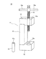
図1〜図3は本発明の実施形態を示している。固体NMR測定用ロータへの試料充填治具10は、図1に示すように、セット治具本体11と押し込み棒15とネジ棒16とから構成し、図2に示すように、ネジ棒16を回転させながらネジ孔14aに通し、ネジ棒16が当接する押し込み棒15をロータ20内部に押し込んでいくことで、セット治具本体11に固定した固体NMR測定用ロータ20(以下、ロータ20という)内の粉末試料30を均一に圧縮するものである。
Hereinafter, embodiments of the present invention will be described with reference to the drawings.
1 to 3 show an embodiment of the present invention. As shown in FIG. 1, a
具体的には、セット治具本体11は、基台部12と、基台部12の一側面から立設した支柱部13と、支柱部13の上端に固定すると共に基台部12と対向させて配置する軸受部14とから構成した逆コ字形状をなし、基台部12には、粉末試料30が供給されたロータ20の下部を挿入しロータ20を固定する嵌合孔12aを設ける一方、軸受部14には、嵌合孔12aと同一軸心位置にネジ棒16を通すネジ孔14aを設けている。
Specifically, the set jig
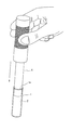
ロータ20は、図3に示すように円筒管状容器からなり、試料供給口である上端開口20aより、固体NMR測定を行う粒径10mm〜1mmの粉末試料30を供給している。なお、ロータ20の外径は3〜10mmφであり、本実施形態においては7mmロータ(ブルカー社製、外径7mm、内径5.55mm、全長18.0mm)を使用している。なお、前記7mmロータの材質はジルコニアであり、底部が筒部と一体型となっている。
As shown in FIG. 3, the
押し込み棒15は、粉末試料30が供給され下部が嵌合孔12aに挿入されたロータ20の上端開口20aから内部に挿入される円柱棒であり、挿入状態において、押し込み棒15は上端開口20aから上方に突出した状態となる。押し込み棒15は、ロータ20の内径に対して−0.01〜−0.5mm(本実施形態においてはロータの内径に対して−0.05mm)の外径を有し、ロータ20の長さ以上の長さを有している。なお、本実施形態における押し込み棒15の材質はステンレスであり、押し込み棒15の全長は18cmとしている。
また、押し込み棒15の上端面には、当接するネジ棒16の先端形状に合わせた凹部15aを設けている。
The
Further, a
ネジ棒16は、ネジ孔14a内で回転しながらネジ棒16先端を押し込み棒15の上端に当接させ、押し込み棒15をロータ20内部に押し込むものである。
ネジ棒16の上側部には、回転操作用の把持部16aを両側に突設しており、把持部16aの長さは、ネジ棒16全長の10〜300%程度[本実施形態においてはネジ棒16全長(52cm)の66%]としている。
The
The upper part of the
なお、前記セット治具本体12の嵌合孔12aの深さは、ロータ20の長さの1/5から1/2(本実施形態においては、ロータ20の長さの6/18)とし、嵌合孔12aの内径は、ロータ20の外径より+0.01mm〜+2mm(本実施形態においては、ロータ20の外径より+0.1mm)としている。
The depth of the
ロータ20内に供給されている粉末試料30の圧縮は、まず、セット治具本体11の嵌合孔12aに、粉末試料30が供給されているロータ20の下部を挿入し、ロータ20を垂直方向に立設保持する。
続いて、ロータ20の上端開口20aに押し込み棒15を挿入すると共に、ネジ孔14aに上方よりネジ棒16を回転しながら挿入し、押し込み棒15の上端にネジ棒16の先端を当接させて押し込み棒15をロータ20内部に押し込んでいく。この際、ネジ棒16を回転させ、粉末試料30の十分に圧縮する。なお、本実施形態においては、圧縮完了時のロータ20底部から粉末試料30上面までの高さが、ロータ20の全長の80%程度となるようにしている。
To compress the
Subsequently, the
前記構成によれば、ネジ棒16を回転させながらネジ孔14aに通し、ネジ棒16の先端をロータ20内に挿入された押し込み棒15に当接させるようにしているため、ネジ棒16の回転力(締め付けトルク)によって、押し込み棒15を高い圧力でロータ20内部に押し込むことができる。これにより、ネジ棒16によって押し込まれる押し込み棒15は、ロータ20内の粉末試料30を高い圧力で均一に圧縮することができ、よって、ロータ20を安定状態で高速回転させることが可能となる。また、ロータ20内に粉末試料30を高密度で充填することができるため、ロータ20内に充填できる試料量を従来の手詰めの場合の1.5倍程度にまで増大させることができ、NMR感度を高めることができる。
According to the above configuration, the
また、前記のように、セット治具本体11を構成する基台部12にロータ20の下部を挿入する嵌合孔12aを設けると共に、基台部12に対面配置される軸受部14の嵌合孔12aと同一軸心位置に、ネジ孔14aを設けることにより、嵌合孔12aにロータ20の下部を挿入し垂直方向に立設保持したロータ20の上端開口20aに挿入した押し込み棒15を、ネジ孔14aに通したネジ棒16が垂直方向に押圧することができる。したがって、ネジ棒16によって押し込まれる押し込み棒15は、ロータ20に供給された粉末試料30を垂直方向に均一に圧縮することができ、より安定したロータの高速回転が可能となる。
Further, as described above, the
さらに、前記のように、ネジ棒16の上側部に回転操作用の把持部16aを両側に突設させることにより、ネジ棒16の回転操作を容易にし、把持部16aに加える力が小さくても大きなトルクを得て、高い圧力で押し込み棒15をロータ20内部に押し込むことができる。
Further, as described above, the gripping
10 試料充填治具
11 セット治具本体
12 基台部
12a 嵌合孔
13 支柱部
14 軸受部
14a ネジ孔
15 押し込み棒
15a 凹部
16 ネジ棒
16a 把持部
20 ロータ
20a 上端開口
30 粉末試料
DESCRIPTION OF
Claims (3)
セット治具本体、押し込み棒およびネジ棒を備え、
前記セット治具本体は、基台部と、該基台部の一側面から立設された支柱部と、該支柱部の上端に固定すると共に前記基台部と対向させて配置する軸受部を備え、前記基台部に前記ロータの下部を挿入する嵌合孔を設けると共に、前記軸受部に前記嵌合孔と同一軸心位置にネジ孔を備え、該ネジ孔を前記嵌合孔に嵌合固定されたロータの試料供給口と対向位置に設け、
前記押し込み棒は前記ロータの試料供給口から内部に挿入すると共に挿入状態で試料供給口から突出するものであり、
前記ネジ棒は上側部に回転操作用の把持部を両側に突設しており、
前記セット治具本体の嵌合孔に前記試料を供給したロータの下部を挿入して、該ロータを垂直方向に立設保持し、該ロータの上端開口の試料供給口に前記押し込み棒を挿入し、前記ネジ孔に上方より前記ネジ棒を回転しながら挿入して前記押し込み棒の上端に当接させて、該押し込み棒を前記ロータ内部に押し込み、該押し込み棒でロータ内に供給されている前記試料を圧縮することを特徴とする固体NMR測定用ロータへの試料充填治具。 A sample filling jig for filling the rotor with a tubular container for solid NMR measurement of the sample,
It is equipped with a set jig body, push rod and screw rod,
The set jig body includes a base part, a support part standing from one side of the base part, and a bearing part that is fixed to the upper end of the support part and is disposed to face the base part. A fitting hole for inserting the lower portion of the rotor is provided in the base part, and a screw hole is provided at the same axial center position as the fitting hole in the bearing part, and the screw hole is fitted into the fitting hole. provided if a fixed sample supply port of the rotor and the pair oriented position,
The push rod is inserted into the rotor from the sample supply port and protrudes from the sample supply port in the inserted state .
The screw rod has a gripping part for rotation operation on the upper side and protrudes on both sides,
Insert the lower part of the rotor to which the sample has been supplied into the fitting hole of the set jig body, hold the rotor upright in the vertical direction, and insert the push rod into the sample supply port at the upper end opening of the rotor. The screw rod is inserted into the screw hole while rotating from above and brought into contact with the upper end of the push rod , and the push rod is pushed into the rotor, and the push rod is fed into the rotor. A sample filling jig for solid-state NMR measurement rotor characterized by compressing a sample.
前記押し込み棒は前記ロータの内径に対して−0.01〜−0.5mmの外径を有すると共にロータの長さ以上の長さを有する円柱棒からなる請求項1に記載の固体NMR測定用ロータへの試料充填治具。 The rotor consists of a cylindrical tube having an outer diameter of 3 to 10 mm,
2. The solid NMR measurement according to claim 1, wherein the push-in rod is a cylindrical rod having an outer diameter of −0.01 to −0.5 mm with respect to an inner diameter of the rotor and a length equal to or longer than the length of the rotor . Sample filling jig for the rotor.
Priority Applications (1)
| Application Number | Priority Date | Filing Date | Title |
|---|---|---|---|
| JP2007142213A JP4999552B2 (en) | 2007-05-29 | 2007-05-29 | Sample filling jig to rotor for solid state NMR measurement |
Applications Claiming Priority (1)
| Application Number | Priority Date | Filing Date | Title |
|---|---|---|---|
| JP2007142213A JP4999552B2 (en) | 2007-05-29 | 2007-05-29 | Sample filling jig to rotor for solid state NMR measurement |
Publications (2)
| Publication Number | Publication Date |
|---|---|
| JP2008298469A JP2008298469A (en) | 2008-12-11 |
| JP4999552B2 true JP4999552B2 (en) | 2012-08-15 |
Family
ID=40172135
Family Applications (1)
| Application Number | Title | Priority Date | Filing Date |
|---|---|---|---|
| JP2007142213A Expired - Fee Related JP4999552B2 (en) | 2007-05-29 | 2007-05-29 | Sample filling jig to rotor for solid state NMR measurement |
Country Status (1)
| Country | Link |
|---|---|
| JP (1) | JP4999552B2 (en) |
Families Citing this family (2)
| Publication number | Priority date | Publication date | Assignee | Title |
|---|---|---|---|---|
| US8692548B2 (en) | 2010-12-13 | 2014-04-08 | Battelle Memorial Institute | Devices and process for high-pressure magic angle spinning nuclear magnetic resonance |
| JP7527177B2 (en) * | 2020-10-29 | 2024-08-02 | 日本電子株式会社 | Sample filling device |
Family Cites Families (3)
| Publication number | Priority date | Publication date | Assignee | Title |
|---|---|---|---|---|
| JPS4859499A (en) * | 1971-11-27 | 1973-08-21 | ||
| JPS6235248U (en) * | 1985-08-22 | 1987-03-02 | ||
| JP4407328B2 (en) * | 2004-03-15 | 2010-02-03 | 住友電気工業株式会社 | Method for producing transparent glass body |
-
2007
- 2007-05-29 JP JP2007142213A patent/JP4999552B2/en not_active Expired - Fee Related
Also Published As
| Publication number | Publication date |
|---|---|
| JP2008298469A (en) | 2008-12-11 |
Similar Documents
| Publication | Publication Date | Title |
|---|---|---|
| JP4999552B2 (en) | Sample filling jig to rotor for solid state NMR measurement | |
| CN201104208Y (en) | Inside diameter edged circle measurer for bearing case | |
| CN208795607U (en) | A kind of accurate torsion thrust measurement testing machine | |
| CN103271756B (en) | Puncture needle holder and puncture frame device | |
| CN212748913U (en) | Soil detection device | |
| CN205702691U (en) | A kind of multifunctional saw quick change construction | |
| KR101571242B1 (en) | Spindle test apparatus | |
| CN102901430B (en) | Axial depth measurement mechanism for under cutting groove | |
| CN204461674U (en) | Force snesor standard torque spanner | |
| JP2008302270A (en) | Testing apparatus of bonding strength of coating and method for testing bonding strength of coating by this testing apparatus | |
| JP2009156808A (en) | Liquid sample analyzer | |
| JP2004243484A (en) | Pipe cutting guide by power tool, support for pipe to be cut, and method of cutting pipe using the power tool and the support | |
| JP6971829B2 (en) | Axial force measuring device | |
| CN214749730U (en) | Chlorophyll fluorescence tester | |
| CN215036845U (en) | A Cylindrical Specimen Holder Based on Durometer | |
| CN104215391A (en) | Standard torque wrench with force transducer | |
| CN223671165U (en) | Hand wheel appurtenance | |
| CN212963180U (en) | An array type tank wall thickness detection device | |
| JP4795047B2 (en) | Rubber sample tension jig, molecular structure / molecular mobility analyzer and analysis method of stretched rubber sample | |
| CN211978108U (en) | Coal mine electromechanical operation vibration monitoring equipment | |
| CN102564662B (en) | The eccentric wheel that center of gravity is constant and measurement mechanism | |
| CN224131705U (en) | An environmentally friendly soil testing box | |
| CN114993924A (en) | Reinforcing steel bar corrosion instrument | |
| CN219455517U (en) | Soil sampler | |
| CN218349377U (en) | Bearing roundness detection device |
Legal Events
| Date | Code | Title | Description |
|---|---|---|---|
| A621 | Written request for application examination |
Free format text: JAPANESE INTERMEDIATE CODE: A621 Effective date: 20100305 |
|
| A977 | Report on retrieval |
Free format text: JAPANESE INTERMEDIATE CODE: A971007 Effective date: 20111221 |
|
| A131 | Notification of reasons for refusal |
Free format text: JAPANESE INTERMEDIATE CODE: A131 Effective date: 20120124 |
|
| A521 | Request for written amendment filed |
Free format text: JAPANESE INTERMEDIATE CODE: A523 Effective date: 20120326 |
|
| TRDD | Decision of grant or rejection written | ||
| A01 | Written decision to grant a patent or to grant a registration (utility model) |
Free format text: JAPANESE INTERMEDIATE CODE: A01 Effective date: 20120417 |
|
| A01 | Written decision to grant a patent or to grant a registration (utility model) |
Free format text: JAPANESE INTERMEDIATE CODE: A01 |
|
| A61 | First payment of annual fees (during grant procedure) |
Free format text: JAPANESE INTERMEDIATE CODE: A61 Effective date: 20120515 |
|
| R150 | Certificate of patent or registration of utility model |
Free format text: JAPANESE INTERMEDIATE CODE: R150 |
|
| FPAY | Renewal fee payment (event date is renewal date of database) |
Free format text: PAYMENT UNTIL: 20150525 Year of fee payment: 3 |
|
| R250 | Receipt of annual fees |
Free format text: JAPANESE INTERMEDIATE CODE: R250 |
|
| LAPS | Cancellation because of no payment of annual fees |