JP4996005B2 - Humidifier for fuel cell - Google Patents
Humidifier for fuel cell Download PDFInfo
- Publication number
- JP4996005B2 JP4996005B2 JP2000265692A JP2000265692A JP4996005B2 JP 4996005 B2 JP4996005 B2 JP 4996005B2 JP 2000265692 A JP2000265692 A JP 2000265692A JP 2000265692 A JP2000265692 A JP 2000265692A JP 4996005 B2 JP4996005 B2 JP 4996005B2
- Authority
- JP
- Japan
- Prior art keywords
- fuel cell
- air
- supply
- hollow fiber
- fiber membrane
- Prior art date
- Legal status (The legal status is an assumption and is not a legal conclusion. Google has not performed a legal analysis and makes no representation as to the accuracy of the status listed.)
- Expired - Fee Related
Links
Images


Classifications
-
- H—ELECTRICITY
- H01—ELECTRIC ELEMENTS
- H01M—PROCESSES OR MEANS, e.g. BATTERIES, FOR THE DIRECT CONVERSION OF CHEMICAL ENERGY INTO ELECTRICAL ENERGY
- H01M8/00—Fuel cells; Manufacture thereof
- H01M8/04—Auxiliary arrangements, e.g. for control of pressure or for circulation of fluids
- H01M8/04082—Arrangements for control of reactant parameters, e.g. pressure or concentration
- H01M8/04089—Arrangements for control of reactant parameters, e.g. pressure or concentration of gaseous reactants
- H01M8/04119—Arrangements for control of reactant parameters, e.g. pressure or concentration of gaseous reactants with simultaneous supply or evacuation of electrolyte; Humidifying or dehumidifying
-
- Y—GENERAL TAGGING OF NEW TECHNOLOGICAL DEVELOPMENTS; GENERAL TAGGING OF CROSS-SECTIONAL TECHNOLOGIES SPANNING OVER SEVERAL SECTIONS OF THE IPC; TECHNICAL SUBJECTS COVERED BY FORMER USPC CROSS-REFERENCE ART COLLECTIONS [XRACs] AND DIGESTS
- Y02—TECHNOLOGIES OR APPLICATIONS FOR MITIGATION OR ADAPTATION AGAINST CLIMATE CHANGE
- Y02E—REDUCTION OF GREENHOUSE GAS [GHG] EMISSIONS, RELATED TO ENERGY GENERATION, TRANSMISSION OR DISTRIBUTION
- Y02E60/00—Enabling technologies; Technologies with a potential or indirect contribution to GHG emissions mitigation
- Y02E60/30—Hydrogen technology
- Y02E60/50—Fuel cells
Landscapes
- Life Sciences & Earth Sciences (AREA)
- Engineering & Computer Science (AREA)
- Manufacturing & Machinery (AREA)
- Sustainable Development (AREA)
- Sustainable Energy (AREA)
- Chemical & Material Sciences (AREA)
- Chemical Kinetics & Catalysis (AREA)
- Electrochemistry (AREA)
- General Chemical & Material Sciences (AREA)
- Fuel Cell (AREA)
- Air Humidification (AREA)
- Separation Using Semi-Permeable Membranes (AREA)
Description
【0001】
【発明の属する技術分野】
本発明は、水透過型加湿器を使用した燃料電池用加湿装置に関する。
【0002】
【従来の技術】
近年、電気自動車の動力源などとして、クリーンでエネルギ効率の優れた燃料電池(固体高分子型燃料電池)が注目されている。この燃料電池は、燃料ガス(水素)及び酸化剤ガス(空気)が供給されると、電気化学的に発電する一種の発電機である。固体高分子型の燃料電池は、その内部にプロトン導電性の固体高分子からなる電解質膜を備えるが、該電解質膜は加湿されることによりその性能を良好に発揮する。一方、電解質膜は、乾燥するとプロトン導伝性が低下すると共に、最悪損傷につながることもある。このため、燃料電池に供給される酸化剤ガスなどの加湿が行われる。例えば、特開平8−273687号公報には、中空糸膜を用いた加湿装置が開示されている。
【0003】
中空糸膜は断面ドーナッツ型をした中空繊維であり、中空糸膜の外側に湿った気体や水(乾燥した気体)を通流し内側に乾燥した気体(湿った気体や水)を通流すると乾燥した気体側に水分が移動し、乾燥した気体が加湿される。通常、中空糸膜は、これを数千本束にしてハウジングに詰めた中空糸膜モジュール(水透過型加湿器)の形で使用される。
【0004】
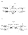
ところで、燃料電池用の加湿装置としては、図5(a)に示すように、中空糸膜モジュール201を並列(Parallel)に接続した構成の加湿装置200Pが知られている。また、図5(b)に示すように、中空糸膜モジュール201(201a,201b)を直列(Series)に接続した構成の加湿装置200Sが知られている。なお、この図5の(a)及び(b)の加湿装置200P,200Sは、燃料電池1の電気化学的反応により生成する生成水を含んだ排出空気Aeの水分を利用して供給空気Aを加湿するものである。
【0005】
【発明が解決しようとする課題】
しかしながら、図5(a)に示す中空糸膜モジュール201を並列に接続した加湿装置200Pでは、それぞれの中空糸膜モジュール201における排出空気Aeと中空糸膜モジュール201における被加湿ガスである供給空気Aの滞留時間が短く、供給空気Aの加湿を多く行うことができない。また、排出空気Aeからの水分回収を充分に行うこともできない。一方、図5(b)に示す中空糸膜モジュール201を直列に接続した加湿装置200Sでは、中空糸膜モジュール201における供給空気Aの滞留時間が長くなる分、供給空気Aの加湿効率を高めることができて好ましいが、中空糸膜モジュール201の数を増やしたほどの加湿効率の向上はない。つまり、最初の中空糸膜モジュール201aを通流した供給空気Aはある程度加湿されているため、燃料電池1の側の中空糸膜モジュール201bでの加湿を効率良く行うことができない。また、排出空気Aeからの水分回収についても同様に、中空糸膜モジュール201の数を増やしたほどの水分回収を行うことができない。
【0006】
そこで、本発明は、供給ガスの加湿を多く行うことができ、また、加湿効率が高くかつ排出ガスからの水分回収を多く行うことのできる燃料電池用加湿装置を提供することを主たる目的とする。
【0007】
【課題を解決するための手段】
前記課題に鑑み本発明者らは、従来例の図5(a)及び(b)に示す構成の加湿装置200P,200Sやその他の構成の加湿装置について、排出空気Aeの量(流量)を一定にして供給空気Aの量(流量)を変化させ、供給空気Aの流量と該供給空気Aの露点(加湿量)の関係を把握する試験を行った。この結果を図6に示す。図6は、横軸に供給空気Aの流量(NL/分)を、縦軸に供給空気Aの露点(℃)をとってある。排出空気Aeの流量は一定である。本発明者らはこの結果から、中空糸膜モジュール201を通流する排出空気Aeの量に対して供給空気Aの量が少なくなると該供給空気Aの露点が高く(加湿量が多く)なるとの知見を得た。加えて、中空糸膜モジュール201における加湿効率を向上するには、各中空糸膜モジュール201における供給空気Aと排出空気Aeの水分濃度差を大きくすればよいとの知見を得た。そして、本発明者らは、かかる知見に基づいて鋭意研究を行い本発明を完成するに至った。
【0009】
即ち、前記課題を解決した本発明のうち請求項1に記載の燃料電池用加湿装置は、燃料電池から排出される排出ガス中の水分を前記燃料電池に供給する供給ガス側へ透過させる複数の水透過型加湿モジュールを備える。そして、それぞれ前記供給ガスが導入される供給ガス入口部及び供給ガス出口部、並びに前記排出ガスが導入される排出ガス入口部及び排出ガス出口部を備えたこの複数の水透過型加湿モジュールは、前記排出ガス側では直列に配管されて前記燃料電池から排出ガスを通流され、前記供給ガス側では並列に配管されて前記燃料電池への供給ガスが通流されるようにした。この構成によれば、水透過型加湿器を通流する供給ガスの量は、水透過型加湿器を通流する排出ガスの量に対して確実に少なくなる。加えて、各水透過型加湿器には、未だ加湿されていない供給ガスが導入される。つまり、各水透過型加湿器における供給ガスと排出ガスの水分濃度差を大きくとることができる。したがって、加湿効率が向上し、供給ガスの加湿が効率良く行われる(加湿も多く行われる)。しかも、排出ガスの配管は水透過型加湿器を直列に接続するので、排出ガスからの水回収も多く行うことができる。
【0010】
また、請求項2に記載の燃料電池用加湿装置は、請求項1に記載の構成において、同じ仕様を有する前記複数の水透過型加湿モジュールのうち、前記排出ガスの流れを基準として上流側に配置されている水透過型加湿モジュールの方が、下流側に配置されている水透過型加湿モジュールの方よりも多い量の前記供給ガスが分配される構成とした。上流側の排出ガスは、燃料電池の生成水を多く保有しており、加湿能力が高い状態である。この加湿能力が高い状態の排出ガスが通流する上流側の水透過型加湿器に多い量の供給ガスを通流することで、加湿能力が少し低下した状態の排出ガスが通流する下流側の水透過型加湿器の負荷を少なくする。これにより、燃料電池用加湿装置全体でみて、供給ガスの加湿が多く行われる。
【0011】
そして、請求項3に記載の燃料電池用加湿装置は、燃料電池から排出される排出ガス中の水分を前記燃料電池に供給する供給ガス側へ透過させる水透過型加湿モジュールを備え、前記水透過型加湿モジュールから排出される前記排出ガスの一部を前記燃料電池と前記水透過型加湿モジュールとの間を通流する前記排出ガスに合流させて戻す手段を備えた構成とした。この構成によれば、確実に排出ガスの量を供給ガスの量よりも多くすることができる。
【0012】
【発明の実施の形態】
以下、本発明の燃料電池用加湿装置(以下「加湿装置」という)の実施形態を、図面を参照して詳細に説明する。
本実施形態で参照する図1は、加湿装置を含む燃料電池システムの全体構成を示す図である。図2は、図1の燃料電池の構成を模式化した説明図である。図3は図1の加湿装置における、(a)は中空糸膜モジュールの構造を示す斜視図であり、(b)は中空糸膜の構造を示す斜視図である。
【0013】
なお、本実施形態の加湿装置2は、2本の中空糸膜モジュール(水透過型加湿器)21a,21bを、供給空気Aの側では並列に配管して接続し、排出空気Aeの側では直列に配管して接続する構成を有する(図1参照)。
【0014】
図1に示す燃料電池システムFCSは、燃料電池1、空気供給装置AS、水素供給装置HS、及び制御装置CUなどから構成される燃料電池1を中核とした発電システムである。
【0015】
〔燃料電池〕
図2に示すように、燃料電池1は、電解質膜1cを挟んでカソード極側(酸素極側)とアノード極側(水素極側)とに分けられ、それぞれの側に白金系の触媒を含んだ電極が設けられ、カソード電極1b及びアノード電極1dを形成している。電解質膜1cとしては固体高分子膜、例えばプロトン交換膜であるパーフロロカーボンスルホン酸膜が使われる。この電解質膜1cは、固体高分子中にプロトン交換基を多数持ち、飽和含水することにより低い比抵抗を示し、プロトン導伝性電解質として機能する。なお、カソード電極1bに含まれる触媒は酸素から酸素イオンを生成する触媒であり、アノード電極1dに含まれる触媒は水素からプロトンを生成する触媒である。
【0016】
また、カソード電極1bの外側にはカソード電極1bに酸化剤ガスとしての供給空気Aを通流するカソード極側ガス通路1aが設けられ、アノード電極1dの外側にはアノード電極1dに燃料ガスとしての供給水素Hを通流するアノード極側ガス通路1eが設けられている。カソード極側ガス通路1aの入口及び出口は空気供給装置ASに接続され、アノード極側ガス通路1eの入口及び出口は水素供給装置HSに接続されている。なお、この図2における燃料電池1は、その構成を模式化して1枚の単セルとして表現してあるが、実際の燃料電池1は、単セルを200枚程度積層した積層体として構成される。また、燃料電池1は、発電の際に電気化学的反応により発熱するため、燃料電池1を冷却する図示しない冷却装置を有する。
【0017】
この燃料電池1は、カソード極側ガス通路1aに供給空気Aが通流され、アノード極側ガス通路1eに供給水素Hが供給されると、アノード電極1dで水素が触媒作用でイオン化してプロトンが生成し、生成したプロトンは、電解質膜1c中を移動してカソード電極1bに到達する。そして、カソード電極1bに到達したプロトンは、触媒の存在下、供給空気Aの酸素から生成した酸素イオンと直ちに反応して水を生成する。生成した水(生成水)及び未使用の酸素を含む供給空気Aは、排出空気Aeとして燃料電池1のカソード極側の出口から排出される。また、アノード電極1dでは水素がイオン化する際に電子e-が生成するが、この生成した電子e-は、モータなどの外部負荷Mを経由してカソード電極1bに達する。
【0018】
〔空気供給装置〕
次に、図1に示すように、空気供給装置ASは、加湿装置2、エアクリーナ3、空気圧縮機4、圧力制御弁5、流量センサQ、温度センサT1,T2、湿度センサH、圧力センサPなどから構成される。
【0019】
図1及び図3を参照して本実施形態の加湿装置2を説明する。
前記のとおり、加湿装置2は、2本の中空糸膜モジュール21a,21bを、供給空気Aの側では並列に配管して接続し、排出空気Aeの側では直列に配管して接続する構成を有する。つまり、中空糸膜モジュール21a,21bは、供給空気Aの側では空気圧縮機4と燃料電池1の間に並列に配管して接続され、排出空気Aeの側では燃料電池1と圧力制御弁5の間に直列に配管して接続されている。なお、中空糸膜モジュール21における供給空気Aと排出空気Aeの流れは、向流になっている。また、2本の中空糸膜モジュール21a,21bは同じ仕様のものである。
【0020】
中空糸膜モジュール21は、図3(a)に示すように、ハウジング31を有し、ハウジング31の内側には、その長手方向に沿って配した水透過性の中空糸膜HF(図3(b)参照)を束ねて構成された中空糸膜束32が収納されている。中空糸膜HFは、その内側から外側に達する口径数nm(ナノメートル)の微細な毛管を多数有しており、毛管中では、蒸気圧が低下して容易に水分の凝縮が起こる。凝縮した水分は、水分の多い方から少ない方に毛管現象(毛管凝縮現象)により吸い出されて中空糸膜HFを透過する。なお、中空糸膜HFの直径は数ミリあるいはそれ以下であり、長さは数十cmである。
【0021】
ハウジング31は、両端が開放された中空円筒形状をしており、その長手方向の一端部側に乾燥空気たる供給空気Aをハウジング31内に導入する供給空気流入口33(供給ガス入口部)が周方向に離間して複数形成されている。また、ハウジング31における長手方向の他端部側には、加湿された供給空気Aの流出口となる複数の供給空気流出口34(供給ガス出口部)が周方向に離間して複数形成されている。
【0022】
一方、ハウジング31に収納される中空糸膜束32は、中空通路を有する水透過性の中空糸膜HFを数千本束ね、一端部側にポッティング部35、他端部側にポッティング部36を設けるようにしてポッティングされている。ハウジング31の一端部側に設けられたポッティング部35は、供給空気流入口33が形成されている位置より若干端部側に位置している(ポッティング部36についても同様である)。
【0023】
また、ポッティング部35の外側には排出空気流出口38(排出ガス出口部)が形成され、ポッティング部36の外側には排出空気流入口37(排出ガス入口部)が形成されている。こうして、ポッティング部35,36を隔てた場合に、排出空気流入口37及び排出空気流出口38は中空糸膜束32を形成する各中空糸膜HFの内側を介して連通する状態になっている。こうして、中空糸膜HFの内側である中空通路を通流する排出空気Aeと中空糸膜HFの外側を通流する供給空気Aが混合しないようになっている。
【0024】
次に、エアクリーナ3は、フィルタなどから構成され、燃料電池1のカソード極側に供給される供給空気Aをろ過して、供給空気Aに含まれるごみなどを取り除く。
【0025】
空気圧縮機4は、スーパーチャージャ及びこれを駆動するモータなどから構成され、エアクリーナ3でろ過された供給空気Aを圧縮して後段の加湿装置2に送出する。送出された供給空気Aは、中空糸膜モジュール21aの供給空気流入口33から加湿装置2に入る。供給空気Aはこの空気圧縮機4により断熱圧縮されることで加熱される。供給空気Aの加熱は、90℃前後の温度で運転される燃料電池1に供給空気Aを供給するため、及び加湿装置2での供給空気Aの加湿(増湿)を容易にするために必要となるものである。
なお、空気圧縮機4は、後述する圧力制御弁5の弁開度が一定の場合、空気圧縮機4を駆動するモータの回転速度を速くすることにより吐出される供給空気Aの圧力(吐出圧)が高くなり、これに対応して供給空気Aの温度が上昇する。一方、モータの回転速度を遅くすることにより該供給空気Aの圧力が低くなり、これに対応して供給空気Aの温度が低下する。
【0026】
圧力制御弁5は、バタフライ弁及びこれを駆動するステッピングモータなどから構成され、空気圧縮機4から吐出される供給空気Aの圧力を圧力制御弁5の弁開度を減少・増加することにより制御する。ちなみに、圧力制御弁5の弁開度を減少すると空気圧縮機4の吐出圧が高くなり、これに対応して供給空気Aの温度が上昇する。また、圧力制御弁5の弁開度を増加すると空気圧縮機4の吐出圧が低くなり、これに対応して供給空気Aeの温度が減少する。なお、本実施形態の圧力制御弁5は、排出空気Aeが通流するラインの末端に設けてある。もちろん、圧力制御弁5を、空気圧縮機4と加湿装置2の間、あるいは加湿装置2と燃料電池1(カソード極入口側/出口側)の間などに設ける構成としてもよい。なお、燃料電池1の圧力を制御する観点からは、圧力制御弁5を燃料電池1の下流側(排出空気Aeが通流するライン)に設けるのが好ましい。また、燃料電池1の下流側の排出空気Aeが通流するラインの燃料電池1と加湿装置2の間に圧力制御弁5を設ける構成とすれば、加湿装置2に供給される排出空気Aeの圧力を下げて排出空気Aeが保有する水分を蒸気化することができるので、加湿装置2における加湿効率が向上する。
【0027】
流量計Qは、差圧流量計などから構成され、エアクリーナ3を通流した後の供給空気Aの流量を検出し、検出信号を制御装置CUに送信する。
【0028】
温度センサT1,T2は、サーミスタあるいは熱電対などから構成される。このうち、温度センサT1は、空気圧縮機4から吐出された供給空気Aの温度を検出し、検出信号を制御装置CUに送信する。温度センサT2は、燃料電池1のカソード極側の入口における供給空気Aの温度を検出し、検出信号を制御装置CUに送信する。
【0029】
湿度センサHは、高分子膜系の湿度センサなどから構成され、燃料電池1のカソード極側入口における供給空気Aの湿度を検出し、検出信号を制御装置CUに送信する。
【0030】
圧力センサPは、ブルドン管、ベローズ、ダイヤフラムあるいはストレインゲージなどから構成され、燃料電池1のカソード極側の入口における供給空気Aの圧力を検出し、検出信号を制御装置CUに送信する。
【0031】
〔水素供給装置〕
図1に示すように、水素供給装置HSは、水素ガスボンベ11、レギュレータ12、水素循環ポンプ13、三方弁14などから構成される。
【0032】
水素ガスボンベ11は、高圧水素容器から構成され、燃料電池1のアノード極側に導入される供給水素Hを貯蔵する。貯蔵する供給水素Hは純水素であり、圧力は15〜20MPe(150〜200kg/cm2G)である。なお、水素ガスボンベ11は、水素吸蔵合金を内蔵し1MPe(10kg/cm2G)程度の圧力で水素を貯蔵する水素吸蔵合金タイプである場合もある。
【0033】
レギュレータ12は、ダイヤフラムや圧力調整バネなどから構成され、高圧で貯蔵された供給水素Hを所定の圧力まで減圧させ、一定圧力で使用できるようにする圧力制御弁である。このレギュレータ12は、ダイヤフラムに入力する基準圧を大気圧にすると、水素ガスボンベ11に貯蔵された供給水素Hの圧力を大気圧近辺にまで減圧することができる。
【0034】
水素循環ポンプ13は、エジェクタなどから構成され、燃料電池1のアノード極側に向かう供給水素Hの流れを利用して、燃料電池1で燃料ガスとして使用された後の供給水素H、つまり燃料電池1のアノード極側から排出され三方弁14を通流する排出水素Heを吸引し循環させる。排出水素Heを循環させることで、大気に放出する水素の量が減るので燃費の向上につながる。
【0035】
三方弁14は、流路切替器から構成され、排出水素Heの流路を切り替えて、排出位置、循環位置にする。三方弁14を排出位置にした場合には、排出水素Heは水素供給装置HSの系外に排出される。また、三方弁14を循環位置にした場合には、排出水素Heは水素循環ポンプ13に導かれる。
【0036】
〔制御装置〕
次に、制御装置CUは、図示しないCPU、メモリ、入出力インタフェイス、A/D変換器、バスなどから構成され、燃料電池システムFCSを統括的に制御すると共に、燃料電池1に供給する供給空気Aの流量、温度、湿度、そして燃料電池1の運転圧力を制御する。
【0037】
〔動作〕
以上説明した燃料電池システムFCSについて、本実施形態の加湿装置2の動作を中心に説明する(図1から図3参照)。
【0038】
空気圧縮機4が作動すると、外気が供給空気Aとしてエアクリーナ3から空気供給装置ASに取り込まれる。圧縮された供給空気Aは分岐して、それぞれの供給空気流入口33,33から2つの中空糸膜モジュール21a,21bに並行して流入する。分岐により各中空糸膜モジュール21a,21bを通流する供給空気Aの量は半分になる。供給空気Aは、中空糸膜束32の間(中空糸膜HFの外側)を通流した後、それぞれの供給空気流出口34,34から流出して合流する。なお、中空糸膜HFの内側には湿潤空気である燃料電池1の排出空気Aeが通流しており、この排出空気Aeが保有している水分が、中空糸膜モジュール21a内の中空糸膜HFを介して乾燥空気である供給空気Aの側に移動し、該供給空気Aを加湿する。
【0039】
このように加湿された供給空気Aは、燃料電池1に供給され、電解質膜1c(図2参照)を適度に加湿する。そして、供給空気A中の酸素と供給水素Hが電気化学的に反応して発電する。この際に生成した生成水は、供給空気Aから転じた排出空気Aeに同伴(保有)されて燃料電池1から排出される。
【0040】
燃料電池1から排出された排出空気Aeは、生成水に起因する多くの水分を保有しており、この排出空気Aeは、排出空気流入口37から燃料電池1の側の中空糸膜モジュール21bに流入し、中空糸膜HFの内側を通流して排出空気流出口38から流出する。中空糸膜HFの外側には、前記した供給空気Aが通流しており、排出空気Aeが保有している水分が、中空糸膜HFを介して乾燥空気である供給空気Aの側に移動し、供給空気Aが加湿される。
【0041】
燃料電池1の側の中空糸膜モジュール21bを通流した排出空気Aeは、排出空気流入口37から次の中空糸膜モジュール21aに流入し、中空糸膜HFの内側を通流して排出空気流出口38から流出する。中空糸膜HFの外側には、前記した供給空気Aが通流しており、排出空気Aeが保有している水分が、中空糸膜HFを介して乾燥空気である供給空気Aの側に移動し、供給空気Aが加湿される。
【0042】
ここで、一方の中空糸膜モジュール21b(燃料電池1の側)には、空気圧縮機4から供給された未加湿の供給空気Aと燃料電池1から排出されたばかりの水分を多く含む排出空気Aeが流入する。両空気A,Aeの水分濃度差は大きく、急速に(効率良く)加湿が行われる。しかも、供給空気Aは分岐されて半分の量が中空糸膜モジュール21bに流入するので、その量は排出空気Aeの量に比べて少ない。したがって、図6から判るように、供給空気Aの露点を高くすることができる。換言すると加湿を多く行うことができる。
【0043】
他方の中空糸膜モジュール21a(圧力制御弁5の側)には、空気圧縮機4から供給された未加湿の供給空気Aと一方の中空糸膜モジュール21bを通流した排出空気Aeが流入する。この他方の中空糸膜モジュール21aでの排出空気Aeは、一方の中空糸膜モジュール21bで供給空気Aに水分交換を行ったものではあるが、なお充分な水分を保有している(中空糸膜モジュール21bでの供給空気Aの量は全体の供給空気Aの量の半分に過ぎないから)。したがって、他方の中空糸膜モジュール21aにおける両空気A,Aeの水分濃度差は大きく、急速に(効率良く)加湿が行われる。しかも、未加湿の供給空気Aは分岐されて半分の量しか他方の中空糸膜モジュール21aに流入しないので、その量は排出空気Aeの量に比べて少ない。したがって他方の中空糸膜モジュール21aでも、供給空気Aの露点を高くすることができる。換言すると加湿を多く行うことができる。
【0044】
また、排出空気Aeは2つの中空糸膜モジュール21,21を直列に通流することに加えて、各中空糸膜モジュール21,21では供給空気Aと排出空気Aeの水分濃度差が大きいことなどから、排出空気Aeからの水分回収を多く行うことができる。
【0045】
なお、本発明は、前記した発明の実施の形態にかかわらず幅広く変形実施することができる。
例えば、図4の変形例に示すように、循環ポンプ22により排出空気Aeを循環する加湿装置2’とすることで、中空糸膜モジュール21を通流する排出空気Aeの量を供給空気Aの量に対して多くなるようにしてもよい。このようにすることで、供給空気Aの加湿を多く行うことができる。
【0046】
また、図2などを参照して説明した本実施形態の加湿装置2について、排出空気Ae〔排出ガス〕の量>供給空気A〔供給ガス〕)の関係を保持しつつ、燃料電池1の側の中空糸膜モジュール21bに、より多くの供給空気Aを通流する構成とするのが好ましい。つまり、燃料電池1から排出された排出空気Aeの含有水分量は多いことから、燃料電池1の側の中空糸膜モジュール21bの加湿能力は高い。したがって、この高い加湿能力を持った中空糸膜モジュール21bにより多い量の供給空気Aを通流することで、水分含有量が少し低下した状態の排出空気Aeが通流する排出空気Aeの流れを基準とした下流側の中空糸膜モジュール21aの負荷を少なくする。このため、加湿装置2全体でみて供給空気Aの加湿がより多く行われるようになる。
同様に、加湿能力の異なる中空糸膜モジュール21を設置することとしてもよい。具体的には、燃料電池1の側の中空糸膜モジュール21(21b)の方が中空糸膜HFの本数が多くなるようにすると共に該モジュール21bのハウジング31の直径を太くする。すると、供給空気A(及び排出空気Ae)の流路の断面積が増えて圧力損失が少なくなり、燃料電池1の側の中空糸膜モジュール21bに対して多くの供給空気Aを通流することができる。このようにすることで、前記説明したように加湿装置2全体でみて供給空気Aの加湿がより多く行われる。また、中空糸膜HFの内側に供給空気Aを通流させた場合(排出空気Aeは中空糸膜HFの外)を考えると、中空糸膜HFの本数が増えれば供給空気Aが通流する流路の断面積が増え、圧力損失が少なくなり、燃料電池1の側の中空糸膜モジュール21bに対して多くの供給空気Aを通流することができる。
同様に、各中空糸膜モジュール21に通流する供給空気Aの量の比率を、中空糸膜モジュール21に供給空気Aを供給する配管径を決めることにより設定することができる。例えば、燃料電池1の側の中空糸膜モジュール21bに供給空気Aを供給(及び排出)する配管径を、中空糸膜モジュール21aに供給空気Aを供給(及び排出)する配管径よりも太くするすることで、弁などの調整手段を用いることなく、自ずと加湿効率の高い燃料電池1の側の中空糸膜モジュール21bに多くの供給空気Aを通流させることができる。このようにすることで、前記説明したように加湿装置2全体でみて供給空気Aの加湿がより多く行われる。
【0047】
また、中空糸膜モジュール内における供給空気と排出空気は向流ではなく、並流としてもよい。また、中空糸膜の内側に排出ガスを、外側に供給ガスを通流することとしてもよい。また、燃料電池の側(一方)の中空糸膜モジュールと圧力制御弁の側(他方)の中空糸膜モジュールに通流する供給空気の量の比率は適宜設定することができる。また、燃料電池は、固体高分子型のものに限定されることなく、他の型式の燃料電池にも、本発明の燃料電池用加湿装置を適用することができる。また、空気圧縮機を燃料電池の後段に設ける構成としてもよい。
さらに、水素供給装置は、水素タンクから燃料電池に水素を供給する構成としたが、メタノールなどの液体原燃料を改質器により改質して水素リッチな燃料ガスを製造し、これを燃料電池に供給する構成としてもよい。また、排出水素を循環使用する/しないにかかわらず、本発明を水素供給装置側に適用してもよい。また、加湿装置の水透過型加湿器も中空糸膜に限定されることはく、他の型式の水透過型加湿器でもよい。また、前記した本実施形態と変形例を組み合わせて実施する構成としてもよい。
【0048】
【発明の効果】
以上説明した本発明のうち請求項1に記載の加湿装置(燃料電池用加湿装置)によれば、簡単な構成で供給ガスの加湿を多く行うことができる。したがって、燃料電池システムを適切な状態で運転することが可能になる。
また、請求項2に記載の加湿装置によれば、簡単な構成で供給ガスの加湿を多く行うことができると共に、加湿効率が高くかつ排出ガスからの水分回収も多く行うことができる。したがって、燃料電池システムをより一層適切な状態で運転することが可能になる。
また、請求項3に記載の加湿装置によれば、各水透過型加湿器における排出ガスの含有水分量の違いを考慮して、加湿装置全体でみて供給ガスの加湿が多く行われる。また、排出ガスからの水分回収を多く行うことができる。したがって、燃料電池システムをより一層適切な状態で運転することが可能になる。
そして、請求項4に記載の加湿装置によれば、確実に排出ガスの量を供給ガスの量よりも多くすることがき、供給ガスの加湿を多く行うことができる。また、排出ガスからの水分回収を多く行うことができる。したがって、燃料電池システムをより一層適切な状態で運転することが可能になる。
【図面の簡単な説明】
【図1】 本発明に係る実施形態の加湿装置を含む燃料電池システムの全体構成を示す図である。
【図2】 図1の燃料電池の構成を模式化した説明図である。
【図3】 図3は図1の加湿装置における、(a)は中空糸膜モジュールの構造を示す斜視図であり、(b)は中空糸膜の構造を示す斜視図である。
【図4】 本発明に係る変形例の加湿装置の構成を示す図である。
【図5】 従来例に係る加湿装置を含む燃料電池システムの構成を示す図であり、(a)は中空糸膜モジュールを並列に接続した加湿装置、(b)は中空糸膜モジュールを直列に接続した加湿装置を示す。
【図6】 供給ガス流量と供給ガス露点の関係を示すグラフである。
【符号の説明】
1…燃料電池
2,2’… 加湿装置(燃料電池用加湿装置)
21(21a,21b)…中空糸膜モジュール(水透過型加湿器)
22 … 循環ポンプ
33 … 供給空気流入口(供給ガス入口部)
34 … 供給空気流出口(供給ガス出口部)
37 … 排出空気流入口(排出ガス入口部)
38 … 排出空気流出口(排出ガス出口部)
A … 供給空気(供給ガス)
Ae … 排出空気(排出ガス)[0001]
BACKGROUND OF THE INVENTION
The present invention relates to a fuel cell humidifier using a water permeable humidifier.
[0002]
[Prior art]
In recent years, fuel cells (solid polymer fuel cells) that are clean and have excellent energy efficiency have attracted attention as power sources for electric vehicles. This fuel cell is a kind of generator that generates electricity electrochemically when fuel gas (hydrogen) and oxidant gas (air) are supplied. A solid polymer type fuel cell includes an electrolyte membrane made of a proton conductive solid polymer inside, and the electrolyte membrane exhibits its performance well by being humidified. On the other hand, when the electrolyte membrane is dried, the proton conductivity is reduced and the electrolyte membrane may be damaged. For this reason, humidification of oxidant gas etc. supplied to a fuel cell is performed. For example, JP-A-8-273687 discloses a humidifying device using a hollow fiber membrane.
[0003]
A hollow fiber membrane is a hollow fiber with a donut-shaped cross section. It passes through a wet gas or water (dry gas) on the outside of the hollow fiber membrane and is dried by passing a dry gas (wet gas or water) on the inside. Moisture moves to the gas side, and the dried gas is humidified. Usually, the hollow fiber membrane is used in the form of a hollow fiber membrane module (water permeable humidifier) in which thousands of bundles are packed in a housing.
[0004]
By the way, as a humidifier for a fuel cell, as shown in FIG. 5A, a
[0005]
[Problems to be solved by the invention]
However, in the
[0006]
SUMMARY OF THE INVENTION Accordingly, it is a primary object of the present invention to provide a fuel cell humidifier capable of performing a high amount of humidification of a supply gas and having high humidification efficiency and capable of performing a large amount of water recovery from exhaust gas. .
[0007]
[Means for Solving the Problems]
In view of the above problems, the present inventors have made constant the amount (flow rate) of the exhaust air Ae for the
[0009]
That is, of the present invention that has solved the
[0010]
Claims 2 A fuel cell humidifier according to
[0011]
And claims 3 The fuel cell humidifier described in 1 includes a water permeable humidification module that allows moisture in exhaust gas discharged from the fuel cell to permeate to a supply gas side that supplies the fuel cell, and is discharged from the water permeable humidification module. The exhaust gas that is partly discharged is joined to the exhaust gas flowing between the fuel cell and the water permeable humidification module. According to this configuration, the amount of exhaust gas can be surely made larger than the amount of supply gas.
[0012]
DETAILED DESCRIPTION OF THE INVENTION
Embodiments of a fuel cell humidifier (hereinafter referred to as “humidifier”) according to the present invention will be described below in detail with reference to the drawings.
FIG. 1 referred to in the present embodiment is a diagram showing an overall configuration of a fuel cell system including a humidifier. FIG. 2 is an explanatory diagram schematically showing the configuration of the fuel cell of FIG. 3A is a perspective view showing the structure of the hollow fiber membrane module in the humidifying apparatus of FIG. 1, and FIG. 3B is a perspective view showing the structure of the hollow fiber membrane.
[0013]
In addition, the
[0014]
A fuel cell system FCS shown in FIG. 1 is a power generation system having a
[0015]
〔Fuel cell〕
As shown in FIG. 2, the
[0016]
Further, a cathode electrode
[0017]
In the
[0018]
[Air supply device]
Next, as shown in FIG. 1, the air supply device AS includes a
[0019]
The
As described above, the
[0020]
As shown in FIG. 3A, the hollow
[0021]
The
[0022]
On the other hand, the hollow fiber membrane bundle 32 accommodated in the
[0023]
Further, an exhaust air outlet 38 (exhaust gas outlet) is formed outside the potting
[0024]
Next, the
[0025]
The air compressor 4 includes a supercharger and a motor that drives the supercharger, compresses the supply air A filtered by the
Note that the air compressor 4 has a pressure (discharge pressure) of the supply air A that is discharged by increasing the rotational speed of the motor that drives the air compressor 4 when the valve opening of the pressure control valve 5 described later is constant. ) Increases, and the temperature of the supply air A rises correspondingly. On the other hand, by reducing the rotation speed of the motor, the pressure of the supply air A becomes lower, and the temperature of the supply air A correspondingly decreases.
[0026]
The pressure control valve 5 includes a butterfly valve and a stepping motor that drives the butterfly valve, and controls the pressure of the supply air A discharged from the air compressor 4 by decreasing or increasing the valve opening degree of the pressure control valve 5. To do. Incidentally, when the valve opening degree of the pressure control valve 5 is decreased, the discharge pressure of the air compressor 4 increases, and the temperature of the supply air A rises correspondingly. Further, when the valve opening degree of the pressure control valve 5 is increased, the discharge pressure of the air compressor 4 is lowered, and the temperature of the supply air Ae is correspondingly reduced. In addition, the pressure control valve 5 of this embodiment is provided at the end of the line through which the exhaust air Ae flows. Of course, the pressure control valve 5 may be provided between the air compressor 4 and the
[0027]
The flow meter Q is composed of a differential pressure flow meter or the like, detects the flow rate of the supply air A after flowing through the
[0028]
The temperature sensors T1, T2 are composed of a thermistor or a thermocouple. Among these, the temperature sensor T1 detects the temperature of the supply air A discharged from the air compressor 4, and transmits a detection signal to the control unit CU. The temperature sensor T2 detects the temperature of the supply air A at the inlet of the cathode side of the
[0029]
The humidity sensor H is composed of a polymer film type humidity sensor or the like, detects the humidity of the supply air A at the cathode electrode side inlet of the
[0030]
The pressure sensor P includes a Bourdon tube, a bellows, a diaphragm, a strain gauge, or the like, detects the pressure of the supply air A at the cathode electrode side inlet of the
[0031]
[Hydrogen supply equipment]
As shown in FIG. 1, the hydrogen supply device HS includes a
[0032]
The
[0033]
The
[0034]
The
[0035]
The three-
[0036]
〔Control device〕
Next, the control unit CU includes a CPU, a memory, an input / output interface, an A / D converter, a bus, and the like (not shown), and controls the fuel cell system FCS as a whole and supplies the
[0037]
[Operation]
The fuel cell system FCS described above will be described focusing on the operation of the
[0038]
When the air compressor 4 is activated, the outside air is taken as supply air A from the
[0039]
The humidified supply air A is supplied to the
[0040]
The exhaust air Ae exhausted from the
[0041]
The discharged air Ae that has flowed through the hollow
[0042]
Here, in one hollow
[0043]
The non-humidified supply air A supplied from the air compressor 4 and the exhaust air Ae flowing through the one hollow
[0044]
In addition, the exhaust air Ae flows through the two hollow
[0045]
It should be noted that the present invention can be widely modified regardless of the embodiment of the invention described above.
For example, as shown in the modification of FIG. 4, the
[0046]
Further, in the
Similarly, it is good also as installing the hollow
Similarly, the ratio of the amount of supply air A flowing through each hollow
[0047]
Further, the supply air and the discharge air in the hollow fiber membrane module may be cocurrent instead of counterflow. Further, the exhaust gas may be flowed inside the hollow fiber membrane and the supply gas may be flowed outside. Moreover, the ratio of the amount of supply air flowing through the hollow fiber membrane module on the fuel cell side (one side) and the hollow fiber membrane module on the pressure control valve side (the other side) can be set as appropriate. The fuel cell is not limited to a solid polymer type, and the fuel cell humidifier of the present invention can be applied to other types of fuel cells. Moreover, it is good also as a structure which provides an air compressor in the back | latter stage of a fuel cell.
Further, the hydrogen supply device is configured to supply hydrogen from the hydrogen tank to the fuel cell, but reforms a liquid raw fuel such as methanol with a reformer to produce a hydrogen-rich fuel gas, which is used as the fuel cell. It is good also as a structure supplied to. Further, the present invention may be applied to the hydrogen supply apparatus side regardless of whether or not the exhausted hydrogen is circulated. Further, the water permeable humidifier of the humidifier is not limited to the hollow fiber membrane, and may be another type of water permeable humidifier. Moreover, it is good also as a structure implemented combining said above-mentioned embodiment and a modification.
[0048]
【Effect of the invention】
According to the humidifying device (humidifying device for a fuel cell) according to the first aspect of the present invention described above, the supply gas can be humidified with a simple configuration. Therefore, the fuel cell system can be operated in an appropriate state.
Further, according to the humidifying device of the second aspect, the supply gas can be humidified with a simple configuration, the humidification efficiency is high, and the moisture recovery from the exhaust gas can be performed a lot. Accordingly, the fuel cell system can be operated in a more appropriate state.
Further, according to the humidifier of the third aspect, in consideration of the difference in the moisture content of the exhaust gas in each water permeable humidifier, the supply gas is humidified as a whole in the humidifier. In addition, a large amount of water can be recovered from the exhaust gas. Accordingly, the fuel cell system can be operated in a more appropriate state.
And according to the humidification apparatus of Claim 4, the quantity of exhaust gas can be reliably made larger than the quantity of supply gas, and humidification of supply gas can be performed much. In addition, a large amount of water can be recovered from the exhaust gas. Accordingly, the fuel cell system can be operated in a more appropriate state.
[Brief description of the drawings]
FIG. 1 is a diagram showing an overall configuration of a fuel cell system including a humidifier according to an embodiment of the present invention.
FIG. 2 is an explanatory diagram schematically showing the configuration of the fuel cell of FIG. 1;
3A is a perspective view showing the structure of a hollow fiber membrane module, and FIG. 3B is a perspective view showing the structure of the hollow fiber membrane in the humidifying device of FIG. 1. FIG.
FIG. 4 is a diagram showing a configuration of a humidifying device according to a modification according to the present invention.
FIG. 5 is a diagram showing a configuration of a fuel cell system including a humidifier according to a conventional example, where (a) is a humidifier in which hollow fiber membrane modules are connected in parallel, and (b) is a hollow fiber membrane module in series. The connected humidifier is shown.
FIG. 6 is a graph showing the relationship between the supply gas flow rate and the supply gas dew point.
[Explanation of symbols]
1. Fuel cell
2, 2 '... Humidifier (humidifier for fuel cell)
21 (21a, 21b) ... hollow fiber membrane module (water permeable humidifier)
22 ... Circulation pump
33 ... Supply air inlet (supply gas inlet)
34 ... Supply air outlet (supply gas outlet)
37 ... Exhaust air inlet (exhaust gas inlet)
38 ... Exhaust air outlet (exhaust gas outlet)
A ... Supply air (supply gas)
Ae ... Exhaust air (exhaust gas)
Claims (3)
さらに前記複数の水透過型加湿モジュールは、前記排出ガス側では直列に配管されて前記燃料電池から排出ガスを通流され、前記供給ガス側では並列に配管されて前記燃料電池への供給ガスが通流されることを特徴とする燃料電池用加湿装置。A humidifier for a fuel cell comprising a plurality of water permeable humidification modules that permeate moisture in an exhaust gas discharged from a fuel cell to a supply gas side that supplies the fuel cell, the plurality of water permeable humidifiers Each of the modules includes a supply gas inlet portion and a supply gas outlet portion into which the supply gas is introduced, and an exhaust gas inlet portion and an exhaust gas outlet portion into which the exhaust gas is introduced,
Further, the plurality of water permeable humidification modules are connected in series on the exhaust gas side to allow exhaust gas to flow from the fuel cell, and are connected in parallel on the supply gas side to supply gas to the fuel cell. A humidifier for a fuel cell, wherein the humidifier is circulated.
前記水透過型加湿モジュールから排出される前記排出ガスの一部を前記燃料電池と前記水透過型加湿モジュールとの間を通流する前記排出ガスに合流させて戻す手段を備えたことを特徴とする燃料電池用加湿装置。A fuel cell humidifying device comprising a water permeable humidification module that permeates moisture in exhaust gas discharged from a fuel cell to a supply gas side that supplies the fuel cell,
And means for returning a part of the exhaust gas discharged from the water permeable humidification module to the exhaust gas flowing between the fuel cell and the water permeable humidification module. A fuel cell humidifier.
Priority Applications (1)
| Application Number | Priority Date | Filing Date | Title |
|---|---|---|---|
| JP2000265692A JP4996005B2 (en) | 2000-09-01 | 2000-09-01 | Humidifier for fuel cell |
Applications Claiming Priority (1)
| Application Number | Priority Date | Filing Date | Title |
|---|---|---|---|
| JP2000265692A JP4996005B2 (en) | 2000-09-01 | 2000-09-01 | Humidifier for fuel cell |
Publications (2)
| Publication Number | Publication Date |
|---|---|
| JP2002075422A JP2002075422A (en) | 2002-03-15 |
| JP4996005B2 true JP4996005B2 (en) | 2012-08-08 |
Family
ID=18752919
Family Applications (1)
| Application Number | Title | Priority Date | Filing Date |
|---|---|---|---|
| JP2000265692A Expired - Fee Related JP4996005B2 (en) | 2000-09-01 | 2000-09-01 | Humidifier for fuel cell |
Country Status (1)
| Country | Link |
|---|---|
| JP (1) | JP4996005B2 (en) |
Families Citing this family (4)
| Publication number | Priority date | Publication date | Assignee | Title |
|---|---|---|---|---|
| KR101028030B1 (en) * | 2007-09-06 | 2011-04-13 | 현대자동차주식회사 | Humidifier for Fuel Cell |
| KR101673667B1 (en) * | 2014-07-31 | 2016-11-07 | 현대자동차주식회사 | Device for adjusting hollow fiber density for humidification device of fuel cell |
| JP6361802B1 (en) * | 2017-07-26 | 2018-07-25 | 栗田工業株式会社 | Gas dissolved water production apparatus and gas dissolved water production method using the same |
| CN113270616B (en) * | 2021-07-20 | 2021-11-09 | 佛山仙湖实验室 | Humidifier system and humidification method for vehicle fuel cell |
Family Cites Families (10)
| Publication number | Priority date | Publication date | Assignee | Title |
|---|---|---|---|---|
| JP3276175B2 (en) * | 1992-10-02 | 2002-04-22 | 三菱重工業株式会社 | Solid polymer electrolyte fuel cell |
| JP3111697B2 (en) * | 1992-10-20 | 2000-11-27 | 富士電機株式会社 | Solid polymer electrolyte fuel cell |
| JPH07245116A (en) * | 1994-03-07 | 1995-09-19 | Toyota Motor Corp | Fuel cell |
| JPH08273687A (en) * | 1995-03-30 | 1996-10-18 | Mazda Motor Corp | Supply gas humidifier of fuel cell |
| JPH10288362A (en) * | 1997-04-10 | 1998-10-27 | Daikin Ind Ltd | Humidification unit |
| JPH1131520A (en) * | 1997-05-13 | 1999-02-02 | Mazda Motor Corp | Polymer electrolyte fuel cell |
| CA2242176C (en) * | 1997-06-30 | 2009-01-27 | Ballard Power Systems Inc. | Solid polymer fuel cell system and method for humidifying and adjusting the temperature of a reactant stream |
| JP3240981B2 (en) * | 1997-12-05 | 2001-12-25 | 三菱電機株式会社 | Electrolytic ozone generator |
| JP4486173B2 (en) * | 1998-08-12 | 2010-06-23 | 三菱重工業株式会社 | Polymer electrolyte fuel cell system |
| JP4295847B2 (en) * | 1998-11-26 | 2009-07-15 | 株式会社東芝 | Polymer electrolyte fuel cell system |
-
2000
- 2000-09-01 JP JP2000265692A patent/JP4996005B2/en not_active Expired - Fee Related
Also Published As
| Publication number | Publication date |
|---|---|
| JP2002075422A (en) | 2002-03-15 |
Similar Documents
| Publication | Publication Date | Title |
|---|---|---|
| US6471195B2 (en) | Humidifier for use with a fuel cell | |
| US6755399B2 (en) | Humidifier | |
| CA2368925C (en) | Fuel cell system | |
| JP3530793B2 (en) | Fuel cell and operating method thereof | |
| US7087328B2 (en) | Fuel cell system and humidification method | |
| JP3871251B2 (en) | Fuel cell humidification system | |
| JP2004503073A (en) | Water recovery on the anode side of a proton exchange thin film fuel cell | |
| JPH08507405A (en) | Solid polymer fuel cell installation including water separation at the anode | |
| US7018732B2 (en) | System and method for management of gas and water in fuel cell system | |
| JP4072707B2 (en) | Solid polymer electrolyte fuel cell power generator and its operation method | |
| US7323262B2 (en) | Method of operating a fuel cell power system to deliver constant power | |
| JP2002158023A (en) | Fuel cell system | |
| JP4806139B2 (en) | Fuel cell humidification system | |
| JP2000208156A (en) | Polymer electrolyte fuel cell system | |
| KR102791248B1 (en) | Humidifier for fuel cell | |
| JP2002075423A (en) | Humidifier for fuel cell | |
| JP4441387B2 (en) | Humidifier | |
| KR101405689B1 (en) | Humidifier for fuel cell | |
| JP4996005B2 (en) | Humidifier for fuel cell | |
| AU2003245138A1 (en) | System and method for management of gas and water in fuel cell system | |
| JPH06119931A (en) | Device of humidifying system for fuel cell | |
| JP2009152013A (en) | Fuel cell system | |
| JP2001202976A (en) | Humidifier | |
| US20040038100A1 (en) | System and method for management of gas and water in fuel cell system | |
| JP2002075418A (en) | Humidifier for fuel cell |
Legal Events
| Date | Code | Title | Description |
|---|---|---|---|
| A621 | Written request for application examination |
Free format text: JAPANESE INTERMEDIATE CODE: A621 Effective date: 20061201 |
|
| A131 | Notification of reasons for refusal |
Free format text: JAPANESE INTERMEDIATE CODE: A131 Effective date: 20100914 |
|
| A521 | Written amendment |
Free format text: JAPANESE INTERMEDIATE CODE: A523 Effective date: 20101112 |
|
| A131 | Notification of reasons for refusal |
Free format text: JAPANESE INTERMEDIATE CODE: A131 Effective date: 20110830 |
|
| A521 | Written amendment |
Free format text: JAPANESE INTERMEDIATE CODE: A523 Effective date: 20111025 |
|
| TRDD | Decision of grant or rejection written | ||
| A01 | Written decision to grant a patent or to grant a registration (utility model) |
Free format text: JAPANESE INTERMEDIATE CODE: A01 Effective date: 20120508 |
|
| A01 | Written decision to grant a patent or to grant a registration (utility model) |
Free format text: JAPANESE INTERMEDIATE CODE: A01 |
|
| A61 | First payment of annual fees (during grant procedure) |
Free format text: JAPANESE INTERMEDIATE CODE: A61 Effective date: 20120511 |
|
| FPAY | Renewal fee payment (event date is renewal date of database) |
Free format text: PAYMENT UNTIL: 20150518 Year of fee payment: 3 |
|
| R150 | Certificate of patent or registration of utility model |
Free format text: JAPANESE INTERMEDIATE CODE: R150 |
|
| LAPS | Cancellation because of no payment of annual fees |