JP4993676B2 - Image coding apparatus and image coding method - Google Patents
Image coding apparatus and image coding method Download PDFInfo
- Publication number
- JP4993676B2 JP4993676B2 JP2006238168A JP2006238168A JP4993676B2 JP 4993676 B2 JP4993676 B2 JP 4993676B2 JP 2006238168 A JP2006238168 A JP 2006238168A JP 2006238168 A JP2006238168 A JP 2006238168A JP 4993676 B2 JP4993676 B2 JP 4993676B2
- Authority
- JP
- Japan
- Prior art keywords
- frame
- image
- block
- prediction
- valued
- Prior art date
- Legal status (The legal status is an assumption and is not a legal conclusion. Google has not performed a legal analysis and makes no representation as to the accuracy of the status listed.)
- Expired - Fee Related
Links
- 238000000034 method Methods 0.000 title claims description 53
- 230000033001 locomotion Effects 0.000 claims description 95
- 238000012545 processing Methods 0.000 claims description 69
- 238000001514 detection method Methods 0.000 claims description 61
- 238000011156 evaluation Methods 0.000 claims description 11
- 238000000605 extraction Methods 0.000 claims description 7
- 239000000284 extract Substances 0.000 claims 1
- 238000013139 quantization Methods 0.000 description 13
- 238000004364 calculation method Methods 0.000 description 9
- 230000003111 delayed effect Effects 0.000 description 8
- 238000012546 transfer Methods 0.000 description 8
- 238000010586 diagram Methods 0.000 description 5
- 230000006870 function Effects 0.000 description 4
- 230000001934 delay Effects 0.000 description 3
- 230000000694 effects Effects 0.000 description 3
- 238000010845 search algorithm Methods 0.000 description 3
- 238000004891 communication Methods 0.000 description 2
- 230000002093 peripheral effect Effects 0.000 description 2
- 230000002123 temporal effect Effects 0.000 description 2
- 230000002411 adverse Effects 0.000 description 1
- 230000005540 biological transmission Effects 0.000 description 1
- 230000006835 compression Effects 0.000 description 1
- 238000007906 compression Methods 0.000 description 1
- 238000004590 computer program Methods 0.000 description 1
- 238000009434 installation Methods 0.000 description 1
- 230000003287 optical effect Effects 0.000 description 1
- 238000004091 panning Methods 0.000 description 1
- 230000004044 response Effects 0.000 description 1
- 239000004065 semiconductor Substances 0.000 description 1
- 230000009466 transformation Effects 0.000 description 1
Images


Classifications
-
- H—ELECTRICITY
- H04—ELECTRIC COMMUNICATION TECHNIQUE
- H04N—PICTORIAL COMMUNICATION, e.g. TELEVISION
- H04N19/00—Methods or arrangements for coding, decoding, compressing or decompressing digital video signals
- H04N19/50—Methods or arrangements for coding, decoding, compressing or decompressing digital video signals using predictive coding
-
- H—ELECTRICITY
- H04—ELECTRIC COMMUNICATION TECHNIQUE
- H04N—PICTORIAL COMMUNICATION, e.g. TELEVISION
- H04N19/00—Methods or arrangements for coding, decoding, compressing or decompressing digital video signals
- H04N19/10—Methods or arrangements for coding, decoding, compressing or decompressing digital video signals using adaptive coding
- H04N19/102—Methods or arrangements for coding, decoding, compressing or decompressing digital video signals using adaptive coding characterised by the element, parameter or selection affected or controlled by the adaptive coding
- H04N19/103—Selection of coding mode or of prediction mode
- H04N19/11—Selection of coding mode or of prediction mode among a plurality of spatial predictive coding modes
-
- H—ELECTRICITY
- H04—ELECTRIC COMMUNICATION TECHNIQUE
- H04N—PICTORIAL COMMUNICATION, e.g. TELEVISION
- H04N19/00—Methods or arrangements for coding, decoding, compressing or decompressing digital video signals
- H04N19/42—Methods or arrangements for coding, decoding, compressing or decompressing digital video signals characterised by implementation details or hardware specially adapted for video compression or decompression, e.g. dedicated software implementation
- H04N19/43—Hardware specially adapted for motion estimation or compensation
-
- H—ELECTRICITY
- H04—ELECTRIC COMMUNICATION TECHNIQUE
- H04N—PICTORIAL COMMUNICATION, e.g. TELEVISION
- H04N19/00—Methods or arrangements for coding, decoding, compressing or decompressing digital video signals
- H04N19/50—Methods or arrangements for coding, decoding, compressing or decompressing digital video signals using predictive coding
- H04N19/503—Methods or arrangements for coding, decoding, compressing or decompressing digital video signals using predictive coding involving temporal prediction
- H04N19/51—Motion estimation or motion compensation
- H04N19/513—Processing of motion vectors
-
- H—ELECTRICITY
- H04—ELECTRIC COMMUNICATION TECHNIQUE
- H04N—PICTORIAL COMMUNICATION, e.g. TELEVISION
- H04N19/00—Methods or arrangements for coding, decoding, compressing or decompressing digital video signals
- H04N19/50—Methods or arrangements for coding, decoding, compressing or decompressing digital video signals using predictive coding
- H04N19/503—Methods or arrangements for coding, decoding, compressing or decompressing digital video signals using predictive coding involving temporal prediction
- H04N19/51—Motion estimation or motion compensation
- H04N19/53—Multi-resolution motion estimation; Hierarchical motion estimation
-
- H—ELECTRICITY
- H04—ELECTRIC COMMUNICATION TECHNIQUE
- H04N—PICTORIAL COMMUNICATION, e.g. TELEVISION
- H04N19/00—Methods or arrangements for coding, decoding, compressing or decompressing digital video signals
- H04N19/50—Methods or arrangements for coding, decoding, compressing or decompressing digital video signals using predictive coding
- H04N19/503—Methods or arrangements for coding, decoding, compressing or decompressing digital video signals using predictive coding involving temporal prediction
- H04N19/51—Motion estimation or motion compensation
- H04N19/533—Motion estimation using multistep search, e.g. 2D-log search or one-at-a-time search [OTS]
-
- H—ELECTRICITY
- H04—ELECTRIC COMMUNICATION TECHNIQUE
- H04N—PICTORIAL COMMUNICATION, e.g. TELEVISION
- H04N19/00—Methods or arrangements for coding, decoding, compressing or decompressing digital video signals
- H04N19/50—Methods or arrangements for coding, decoding, compressing or decompressing digital video signals using predictive coding
- H04N19/503—Methods or arrangements for coding, decoding, compressing or decompressing digital video signals using predictive coding involving temporal prediction
- H04N19/51—Motion estimation or motion compensation
- H04N19/57—Motion estimation characterised by a search window with variable size or shape
-
- H—ELECTRICITY
- H04—ELECTRIC COMMUNICATION TECHNIQUE
- H04N—PICTORIAL COMMUNICATION, e.g. TELEVISION
- H04N19/00—Methods or arrangements for coding, decoding, compressing or decompressing digital video signals
- H04N19/50—Methods or arrangements for coding, decoding, compressing or decompressing digital video signals using predictive coding
- H04N19/59—Methods or arrangements for coding, decoding, compressing or decompressing digital video signals using predictive coding involving spatial sub-sampling or interpolation, e.g. alteration of picture size or resolution
-
- H—ELECTRICITY
- H04—ELECTRIC COMMUNICATION TECHNIQUE
- H04N—PICTORIAL COMMUNICATION, e.g. TELEVISION
- H04N19/00—Methods or arrangements for coding, decoding, compressing or decompressing digital video signals
- H04N19/50—Methods or arrangements for coding, decoding, compressing or decompressing digital video signals using predictive coding
- H04N19/593—Methods or arrangements for coding, decoding, compressing or decompressing digital video signals using predictive coding involving spatial prediction techniques
Description
本発明は、画像符号化技術に関し、特に動き補償を用いた画像符号化技術に関する。 The present invention relates to an image encoding technique, and more particularly to an image encoding technique using motion compensation.
国際標準として定められた動画像の圧縮符号化方式として、ITU-T Recommendation H.264又はISO/IEC International Standard 14496-10(以下、単にH.264と記す)や、MPEG2方式等が知られている。
これらの符号化方式では、画像を複数の矩形ブロック(マクロブロック)に分割し、マクロブロック単位で符号化を行う。また、動画像を構成するフレーム画像が時間的及び空間的に大きな相関を持つ性質を利用して符号量を削減している。
ITU-T Recommendation H.264 or ISO / IEC International Standard 14496-10 (hereinafter simply referred to as H.264), MPEG2 format, etc. are known as compression encoding methods for moving images defined as international standards. Yes.
In these encoding methods, an image is divided into a plurality of rectangular blocks (macroblocks), and encoding is performed in units of macroblocks. Also, the amount of codes is reduced by utilizing the property that the frame images constituting the moving image have a large temporal and spatial correlation.
時間的な相関性を利用した符号化方式としては、動き補償フレーム間予測符号化方式が広く用いられている。これは、符号化対象マクロブロックの動き情報(動きベクトル)を検出し、この動き情報を用いて生成した予測画像と、符号化対象マクロブロックとの差分を符号化するものである。 As an encoding method using temporal correlation, a motion-compensated interframe prediction encoding method is widely used. This detects motion information (motion vector) of the encoding target macroblock, and encodes the difference between the predicted image generated using the motion information and the encoding target macroblock.
また、空間的な相関性を利用した符号化方式としては、フレーム内予測符号化方式が広く用いられている。これは、同一フレーム内の、符号化対象マクロブロックの周囲のマクロブロック内の画素を用いて予測画像を生成し、その予測画像と符号化対象マクロブロックとの差分を符号化するものである。 In addition, an intra-frame predictive coding method is widely used as a coding method using spatial correlation. In this method, a prediction image is generated using pixels in a macroblock around the encoding target macroblock in the same frame, and a difference between the prediction image and the encoding target macroblock is encoded.
特にこのフレーム内予測方式は、複数の予測方向に対応する多くの予測モードを有し、他の符号化方式と比べてフレーム内における予測精度が高い。H.264におけるフレーム内予測符号化ツール及び他の符号化ツールの詳細は、それぞれの勧告書を参照されたい。 In particular, this intra-frame prediction method has many prediction modes corresponding to a plurality of prediction directions, and has higher prediction accuracy in the frame than other encoding methods. For details of the intraframe predictive coding tool and other coding tools in H.264, refer to the respective recommendations.
符号化対象となる画像の多様化などにより、様々な符号化方式が標準化されてきているが、動き補償フレーム間予測符号化方式における動き検出については、新しく標準化された符号化方式であっても、従前の手法が踏襲されたままである。
従前の動き検出の手法としては、例えば、特許文献1、非特許文献1、非特許文献2及び非特許文献3に記載されるようなものがある。
Various coding schemes have been standardized due to diversification of images to be coded, etc., but motion detection in the motion compensation interframe predictive coding scheme is a newly standardized coding scheme. The previous method is still followed.
Examples of conventional motion detection methods include those described in
ここで、従前から行なわれている、一般的なブロックマッチングによる動き検出手法について簡単に説明する。
図6は、従来の符号化装置における動き検出処理に係る構成を模式的に示した図である。
図において、動き検出装置601は、参照フレームメモリ604とバス603を介して接続されている。参照フレームメモリ604には、現処理対象フレームの動き検出のために参照する参照フレームが格納される。動き検出装置601はさらに、現処理対象ブロックの動き検出処理に必要な探索範囲の参照データを格納する、探索範囲RAM602を備える。
Here, a conventional motion detection method based on block matching, which has been conventionally performed, will be briefly described.
FIG. 6 is a diagram schematically showing a configuration relating to motion detection processing in a conventional encoding device.
In the figure, a
動き検出装置601は、現処理対象ブロックの動き検出処理を行う際に、まず参照フレームメモリ604より、探索範囲の参照データをバス603を介して読み出し、探索範囲RAM602に格納する。そして、現処理対象ブロックのデータと、探索範囲RAM602内の参照データとの位置をずらしながら、順次マッチングをとり、最も類似度の高い位置を動きベクトルとして検出する。
When performing motion detection processing for the current processing target block, the
参照データは処理対象ブロック毎に異なるが、図5に示すように、現在処理中のブロックの探索範囲と、直前に処理したブロックの探索範囲とには重複部分がある。そのため、参照データを探索範囲RAM602へ書き込む際には、重複部分を除いた探索範囲のデータのみを書き込むのが普通である。
Although the reference data differs for each processing target block, as shown in FIG. 5, there is an overlap between the search range of the block currently being processed and the search range of the block processed immediately before. Therefore, when writing the reference data to the
近年、符号化対象となる動画像コンテンツは、1フレーム当たりの画素数及びフレーム・レートが増加する傾向にあり、単位時間あたりに符号化処理すべきデータ量が増加している。 In recent years, moving image content to be encoded tends to increase the number of pixels per frame and the frame rate, and the amount of data to be encoded per unit time has increased.
そのため、参照フレームメモリ604から動き検出範囲の参照データをバス603を介して読み出し、探索範囲RAM602に格納する処理における、バス603の単位時間当たりのデータ転送量が増大することになる。一般的に、参照フレームメモリ604は、動き検出装置601を含む画像符号化装置等におけるCPUや他の画像処理部なども用いる共用メモリ空間の一部であることが多い。
Therefore, the data transfer amount per unit time of the bus 603 increases in the process of reading the reference data of the motion detection range from the reference frame memory 604 via the bus 603 and storing it in the
そのため、参照フレームメモリ604から探索範囲RAM602への転送量の増大は、共用メモリを使用する他の構成要素の処理に影響を及ぼし、場合によって画像符号化装置全体の正常動作を妨げる事態を招く。
For this reason, an increase in the transfer amount from the reference frame memory 604 to the
このような事態を防止するには、参照フレームメモリ604を共用メモリの一部空間ではなく、専用メモリとして設ける等の対策が必要である。しかし、このような対策は、回路規模やコストの増加を伴うため、好ましくない。 In order to prevent such a situation, it is necessary to take measures such as providing the reference frame memory 604 as a dedicated memory instead of a partial space of the shared memory. However, such measures are not preferable because they involve an increase in circuit scale and cost.
H.264等、フレーム内予測符号化及びフレーム間予測符号化を併用する符号化方式を実現する従来の符号化装置において、フレーム間予測符号化に用いる動き検出処理に際し、フレーム内予測符号化との親和性は考慮されてこなかった。 In a conventional encoding device that realizes an encoding scheme that uses both intra-frame predictive coding and inter-frame predictive coding, such as H.264, in the motion detection process used for inter-frame predictive coding, intra-frame predictive coding and The affinity of has not been considered.
また、H.264など新しい符号化方式は、それ以前の符号化方式と比べて符号化効率が高い反面複雑であり、多くの演算を必要とする。そのため、符号化処理時間の増大や回路規模の増大を抑制するのが困難であった。
また、従来の動き検出処理では、探索範囲の参照データ群を準備するためのデータ伝送量が多く、バスの帯域を圧迫していた。
In addition, a new encoding method such as H.264 has higher encoding efficiency than the previous encoding method, but is complicated and requires many operations. For this reason, it has been difficult to suppress an increase in encoding processing time and an increase in circuit scale.
Further, in the conventional motion detection processing, the amount of data transmission for preparing the reference data group in the search range is large, and the bandwidth of the bus is pressed.
本発明はこのような従来技術の課題に鑑みなされたものであり、フレーム内予測符号化及びフレーム間予測符号化を併用する画像符号化装置及び画像符号化方法において、動き検出に必要なデータ転送量及び符号化に必要な演算量を低減することにある。 The present invention has been made in view of the above-described problems of the prior art, and in an image encoding apparatus and an image encoding method using both intraframe prediction encoding and interframe prediction encoding, data transfer necessary for motion detection is provided. It is to reduce the amount and the amount of calculation required for encoding.
上述の目的は、動画像のフレームをブロック単位で符号化する画像符号化装置であって、フレーム中の処理対象ブロックに対する第1の予測画像ブロックを、処理対象ブロックが含まれるフレームと同一フレーム内から生成するフレーム内予測手段と、処理対象ブロックが含まれるフレームの高周波成分を抽出する高周波成分抽出手段と、高周波成分抽出手段によって抽出された高周波成分の階調数を低減し、N値化(Nは2以上の整数)されたフレームを生成するN値化画像生成手段と、N値化画像生成手段が過去に生成したN値化されたフレームを記憶する記憶手段と、記憶手段に記憶されたN値化したフレームを用いて、処理対象ブロックに対する第2の予測画像ブロックを、処理対象ブロックが含まれるフレームと異なるフレーム内から生成するフレーム間予測手段と、予め定められた評価方法に従って、フレーム内予測手段によって生成された第1の予測画像ブロックとフレーム間予測手段によって生成された第2の予測画像ブロックとの一方を選択する選択手段と、第1及び第2の予測画像ブロックのうち、選択手段が選択した予測画像ブロックを用いて、処理対象ブロックを符号化する符号化手段とを有することを特徴とする画像符号化装置によって達成される。 The above-described object is an image encoding device that encodes a frame of a moving image in units of blocks, and the first predicted image block for the processing target block in the frame is included in the same frame as the frame including the processing target block. The intra-frame prediction means generated from the above, the high-frequency component extraction means for extracting the high-frequency component of the frame including the processing target block, and the number of gradations of the high-frequency component extracted by the high-frequency component extraction means are reduced to an N-value ( N is an integer greater than or equal to 2) N-valued image generation means for generating frames, storage means for storing N-valued frames generated by the N-valued image generation means in the past, and storage means Using the N-valued frame, the second predicted image block for the processing target block is included in a frame different from the frame including the processing target block. One of the first prediction image block generated by the intra-frame prediction means and the second prediction image block generated by the inter-frame prediction means in accordance with a predetermined evaluation method. selection means for selecting, among the first and second prediction image block, and characterized by using the predictive image blocks are selected means selected, the target block to have a coding means for coding This is achieved by an image encoding device.
また、上述の目的は、動画像のフレームをブロック単位で符号化する画像符号化方法であって、フレーム中の処理対象ブロックに対する第1の予測画像ブロックを、処理対象ブロックが含まれるフレームと同一フレーム内から生成するフレーム内予測工程と、処理対象ブロックが含まれるフレームの高周波成分を抽出する高周波成分抽出工程と、高周波成分抽出工程によって抽出された高周波成分の階調数を低減し、N値化(Nは2以上の整数)されたフレームを生成するN値化画像生成工程と、N値化画像生成工程で過去に生成されたN値化されたフレームを記憶手段に記憶する記憶工程と、記憶手段に記憶されたN値化したフレームを用いて、処理対象ブロックに対する第2の予測画像ブロックを、処理対象ブロックが含まれるフレームと異なるフレーム内から生成するフレーム間予測工程と、予め定められた評価方法に従って、フレーム内予測工程において生成された第1の予測画像ブロックとフレーム間予測工程において生成された第2の予測画像ブロックとの一方を選択する選択工程と、第1及び第2の予測画像ブロックのうち、選択工程において選択された予測画像ブロックを用いて、処理対象ブロックを符号化する符号化工程とを有することを特徴とする画像符号化方法によっても達成される。 The above-described object is an image encoding method for encoding a frame of a moving image in units of blocks, and the first predicted image block for the processing target block in the frame is the same as the frame including the processing target block. Reducing the number of tones of the high-frequency component extracted by the intra-frame prediction process generated from the frame, the high-frequency component extraction process for extracting the high-frequency component of the frame including the processing target block, and the high-frequency component extraction process , and N value An N-valued image generation step for generating a converted frame (N is an integer equal to or greater than 2), and a storage step for storing in the storage means N-valued frames generated in the past in the N-valued image generation step , frame by using the stored N-valued frame in the storage means, the second predicted image blocks for the target block includes the target block An inter-frame prediction step generated from within a different frame, a first prediction image block generated in the intra-frame prediction step and a second prediction image block generated in the inter-frame prediction step according to a predetermined evaluation method; while a selection step of selecting of one of the first and second prediction image block using the selected prediction image block in the selection process, the target block to have a the encoding step of encoding It is also achieved by an image encoding method characterized by
このような構成により、フレーム内予測符号化及びフレーム間予測符号化を併用する符号化装置及び画像符号化方法において、動き検出に必要なデータ転送量及び符号化に必要な演算量を低減することが可能となる。 With such a configuration, the amount of data transfer necessary for motion detection and the amount of computation necessary for encoding are reduced in an encoding device and an image encoding method that use both intraframe prediction encoding and interframe prediction encoding. Is possible.
以下、図面を参照して本発明をその好適な実施形態に基づいて詳細に説明する。
図1は、本発明の第1の実施形態に係る画像符号化装置の構成例を示す図である。
動画像符号化装置100は、以下の構成要素を有してなる。フレーム内予測部101、二値化画像生成部102、二値化画像フレームバッファ103、フレーム間予測部104、選択器105、差分生成器106、直交変換部107、エントロピー符号化部108、局所復号部109及び、フレームバッファ110。
Hereinafter, the present invention will be described in detail based on preferred embodiments with reference to the drawings.
FIG. 1 is a diagram illustrating a configuration example of an image encoding device according to the first embodiment of the present invention.
The moving
符号化対象動画像として入力される原画像は、フレームを矩形領域に分割した、複数の画素群よりなるブロックの単位でそれぞれフレーム内予測部101、二値化画像生成部102、フレーム間予測部104、及び差分生成器106へと入力される。
The original image input as the encoding target moving image includes an
フレーム内予測部101は、入力された原画像よりフレーム内予測を行ない、フレーム内予測画像を生成して選択器105へと出力する。
二値化画像生成部102は、入力された原画像の高周波成分の特徴を抽出して二値化画像を生成し、フレーム間予測部104及び二値化画像フレームバッファ103へと出力する。
The
The binarized
二値化画像フレームバッファ103は、二値化画像生成部102より出力された二値化画像を記憶保持し、少なくとも次のフレームまで遅延させた後、二値化遅延フレーム画像つまり参照フレーム画像としてフレーム間予測部104へと出力する。
フレーム間予測部104は、原画像、二値化画像、二値化遅延フレーム画像及び遅延フレーム画像を元にフレーム間予測を行ない、フレーム間予測画像を生成して選択器105へと出力する。
The binarized image frame buffer 103 stores and holds the binarized image output from the binarized
The
選択器105は、フレーム内予測部101より出力されるフレーム内予測画像及び、フレーム間予測部より出力されるフレーム間予測画像のうち、いずれか一方を選択して被選択予測画像として差分生成器106へと出力する。
差分生成器106は、原画像と選択器105より出力される被選択予測画像との差分をとり、予測差分画像として直交変換部107へと出力する。
The
The
直交変換部107は、差分生成器106より出力される予測差分画像に直交変換及び量子化処理を施し、量子化変換係数としてエントロピー符号化部108及び局所復号部109へと出力する。
The
エントロピー符号化部108は、直交変換部107より出力される変換係数、フレーム内予測のモード情報(図示されない)及びフレーム間予測の動き情報(図示されない)についてそれぞれエントロピー符号化を施し、符号化ストリームとして出力する。
選択器105、差分生成器106、直交変換部107及びエントロピー符号化部108は、全体として符号化部120を構成する。符号化部120は、フレーム内予測画像とフレーム間予測画像の選択された一方と処理対象ブロックとの予測差分画像を符号化する手段として機能する。
The
The
局所復号部109は、直交変換部107より出力される変換係数に対して逆量子化及び逆直交変換を施し、局所復号画像としてフレームバッファ110へと出力する。
フレームバッファ110は、局所復号部109より出力される局所復号画像を記憶保持し、少なくとも次のフレームまで遅延させた後、遅延フレーム画像としてフレーム間予測部104へと出力する。
The
The
次に、本発明の実施形態の動画像符号化装置の動作について説明する。
多値画像(M(M>2)値画像)である原画像が入力されると、フレーム内予測部101では、所定サイズの矩形ブロック(以下、単にブロックという)を単位としたフレーム内予測を行なう。フレーム内予測部101は、適切なモード(予測方向、予測単位ブロックサイズ等)を決定し、対応する近隣画素からブロック内の画素を予測したフレーム内予測画像(第1の予測画像ブロック)を生成して出力する。
Next, the operation of the moving picture coding apparatus according to the embodiment of the present invention will be described.
When an original image that is a multi-value image (M (M> 2) value image) is input, the
また、フレーム内予測部101は、生成したフレーム内予測画像と、処理対象ブロックの画像との類似度を評価する指標として、例えば後述するSAD値を算出する。この指標の値は、例えば選択器105において予測画像を選択する際の評価基準として利用することができる。
一方、原画像は二値化画像生成部102へも入力され、ブロック単位で二値化処理が適用される。
In addition, the
On the other hand, the original image is also input to the binarized
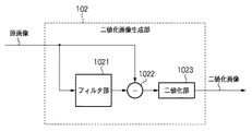
図2は二値化画像生成部102の内部構成例を示した図である。
二値化画像生成部102はフィルタ部1021、差分生成器1022、及び二値化部1023より構成される。原画像はブロック単位でフィルタ部1021及び差分生成器1022へと入力される。フィルタ部1021において、入力された原画像ブロックはフィルタ処理が施され、被フィルタ画像として差分生成器1022へと出力される。
FIG. 2 is a diagram illustrating an internal configuration example of the binarized
The binarized
フィルタ部1021は、後述の差分生成器1022と組合わせて原画像の高周波成分の特徴を抽出するためのフィルタであり、例えば原画像の有する空間周波数成分より低いカットオフ周波数である低域通過フィルタを用いることができる。フィルタ部1021に用いる低域通過フィルタとしては、例えば図3(a)〜図3(c)に示されるような2次元タップ係数を有する空間フィルタを例示することができる。この時フィルタのタップ数に応じて、ブロックの周辺画素を多く用いる事でブロック分割によるブロック端部の悪影響が低減される。差分生成器1022は、原画像とフィルタ部1021より出力される被フィルタ画像との差分を求め、高周波成分抽出画像として二値化部1023へ出力する。
The
原画像の持つ各画素値と、低域通過フィルタ処理が施された被フィルタ画像の対応画素値との差分をとることによって、原画像の高周波成分の持つ特徴画像を得ることができる。差分生成器1022より出力される高周波成分抽出画像は、二値化部1023において二値化処理が施され、二値化画像として出力される。二値化部1023は、高周波成分抽出画像が持つ各画素値について、所定値以上、例えば1以上の画素は「1」、そうでない画素は「0」として二値化する。
By taking the difference between each pixel value of the original image and the corresponding pixel value of the filtered image that has been subjected to the low-pass filter processing, a feature image possessed by the high-frequency component of the original image can be obtained. The high frequency component extracted image output from the
こうして二値化画像生成部102によって得られた二値化画像は、原画像の高周波成分の特徴が反映された二値化画像となる。このように原画像の高周波成分の特徴が反映された二値化画像を用いる理由は、概ね以下に述べる理由による。
The binarized image obtained by the binarized
第一の理由は、二値化画像を用いることによって画像データ量が大幅に減少することである。これにより、二値化フレームバッファ103へのアクセス量及び、動き検出のための演算量を低減させることが可能となる。 The first reason is that the amount of image data is greatly reduced by using a binarized image. As a result, the access amount to the binarized frame buffer 103 and the calculation amount for motion detection can be reduced.
第二の理由としては、高周波成分の特徴が反映された二値化画像は、フレーム間の差分、即ち動きの特徴が現れやすいためである。そのため、高周波成分の特徴が反映された二値化画像を用いて動き検出を行なうことによって、原画像が高周波成分を十分に有する画像であれば、精度良く動きを検出することが可能となる。 The second reason is that the binarized image reflecting the characteristics of the high-frequency component tends to show the difference between frames, that is, the characteristics of motion. Therefore, by performing motion detection using a binarized image in which the characteristics of the high frequency component are reflected, it is possible to detect the motion with high accuracy if the original image is an image having a sufficient high frequency component.
第三の理由としては、空間的相関を利用したフレーム内予測と併用する場合、結果として高い符号化効率を得られるためである。前述したように、原画像が高周波成分を十分に有する画像であれば、二値化画像を用いることで精度良く動き検出ができる。しかし反面、原画像の高周波成分が少ない場合には、二値化画像に画像の特徴が反映されにくくなり、動き検出の精度は低下する。この点、フレーム内予測においては、近隣の画素から予測画素を生成するため、画素間相関が高いほど、すなわち高周波成分が少ない画像であるほど予測精度が向上する。従って、高周波成分が少ない原画像に対してはフレーム内予測が有効である。 The third reason is that when combined with intra-frame prediction using spatial correlation, high coding efficiency can be obtained as a result. As described above, if the original image has sufficient high-frequency components, motion can be detected with high accuracy by using a binarized image. On the other hand, when the high-frequency component of the original image is small, image characteristics are not easily reflected in the binarized image, and the accuracy of motion detection is reduced. In this regard, in intra-frame prediction, a prediction pixel is generated from neighboring pixels, so that the higher the correlation between pixels, that is, the lower the high-frequency component, the higher the prediction accuracy. Therefore, intra-frame prediction is effective for an original image with few high-frequency components.
実際の動画像では、高速なパニング等によって画面内の動きが大きくなっているようなケースでは、隣接画素間相関が高くなり、高周波成分が少なくなる傾向があるため、フレーム内予測の予測精度が高くなる。従って高周波成分の特徴が反映された二値化画像を用いて動き検出を行ないフレーム間予測を行なうと同時に、空間的相関を利用したフレーム内予測を行なうことによって、全体で高い符号化効率を得ることができる。 In actual moving images, when the movement in the screen is large due to high-speed panning, etc., the correlation between adjacent pixels tends to increase and the high-frequency component tends to decrease. Get higher. Therefore, by performing motion detection using a binarized image that reflects the characteristics of high-frequency components and performing inter-frame prediction, and performing intra-frame prediction using spatial correlation, high coding efficiency is obtained as a whole. be able to.
二値化画像生成部102において得られた二値化画像ブロックは、現在処理対象となっている原画像ブロックの動き検出に用いるため、フレーム間予測部104へと送られる。さらに、次フレーム画像以降の動き検出時に参照画像として用いるために、一旦、二値化画像フレームバッファ103へ送られ、記憶保持される。
The binarized image block obtained by the binarized
フレーム間予測部104において、二値化画像及び原画像を用いて動き検出処理に基づくフレーム間予測が行なわれる。図4は、フレーム間予測部104の内部構成例を示す図である。以下、図4を用いてフレーム間予測部104の動作を説明する。
The
ブロック単位で入力される原画像は、ブロックRAM1041に格納される。また、同じくブロック単位で入力される二値化画像は、二値化画像ブロックRAM1042に格納される。また、二値化画像フレームバッファ103から読み出された二値化遅延フレーム画像は二値化画像探索範囲RAM1043に格納される。
The original image input in units of blocks is stored in the
二値化画像ブロックRAM1042及び二値化画像探索範囲RAM1043への格納がそれぞれ終了すると、二値化画像動き検出部1045においてブロックマッチング処理に基づく動き検出処理が開始される。二値化画像ブロックRAM1042は、二値化画像動き検出部1045の必要に応じて、適宜処理対象二値化画像ブロックのデータを出力する。二値化画像探索範囲RAM1043は、参照フレームとして用いる二値化遅延フレーム画像の参照データのうち、探索範囲として設定された二値化画像参照データ群を格納し、二値化画像動き検出部1045の必要に応じて、参照データを出力する。
When the storage in the binarized
二値化画像動き検出部1045は、処理対象ブロックに対応する探索範囲を計算する。そして、計算された探索範囲に含まれる参照データ群のうち、既に二値化画像探索範囲RAM1043内に書き込まれている参照データを除いた新規部分のみを二値化画像フレームバッファ103から取得し、二値化画像探索範囲RAM1043を更新する。
The binarized image
ところで、探索範囲参照データをバッファから取得する処理において、参照データを本来の階調のまま取得する場合と、本実施形態のように二値化したものを取得する場合とではデータ量に大幅な差が生じる。例えば、原画像が256階調を持っていたとすると、1画素当り8ビット必要であり、二値化画像の8倍のデータを取得する必要がある。このように、二値化画像を用いて動き検出処理を行なうことで、探索範囲の参照データの転送量を大きく低減させることが可能である。 By the way, in the process of acquiring the search range reference data from the buffer, the case where the reference data is acquired in its original gradation and the case where the binarized data is acquired as in the present embodiment has a large amount of data. There is a difference. For example, if the original image has 256 gradations, 8 bits are required per pixel, and 8 times as much data as the binarized image must be acquired. As described above, by performing the motion detection process using the binarized image, it is possible to greatly reduce the transfer amount of the reference data in the search range.
また、二値化画像動き検出部1045は、二値化画像ブロックRAM1042より処理対象二値化画像ブロックのデータを読み出し、二値化画像探索範囲RAM1043より読み出した探索範囲内の二値化画像参照データとブロックマッチングを行なう。探索範囲内における二値化画像参照データに対し、処理対象二値化画像ブロックデータを順次ずらしていきながら順次マッチングを行う。そして、最も高い類似度と評価された際の位置をもとに第1の動きベクトルMVbinを算出し、動き検出部1046へと出力する。
Also, the binarized image
二値化画像ブロック相互の類似度の指標としては、対応画素間の排他的論理和の合計(XORSUM)が一般的によく用いられる。例えば、処理対象二値化画像ブロック(x画素×y画素)の各画素値をOrgbin(0,0)〜Orgbin(x-1,y-1)とし、マッチング対象として対応する二値化画像参照データ(x画素×y画素)の各画素値をRefbin(0,0)〜Refbin(x-1,y-1)とすると、これらのXORSUM値は、下記式(1)より得られる。 As an index of the degree of similarity between binarized image blocks, the sum of exclusive OR (XORSUM) between corresponding pixels is generally used. For example, each pixel value of the processing target binarized image block (x pixel × y pixel) is set to Orgbin (0,0) to Orgbin (x-1, y-1), and the corresponding binarized image is referred to as a matching target. If each pixel value of data (x pixel × y pixel) is Refbin (0,0) to Refbin (x−1, y−1), these XORSUM values are obtained from the following equation (1).

排他的論理和は、入力値が異なる際に真となるため、XORSUM値が小さいほど類似度が高く、大きいほど類似度が低いと見なすことができる。 Since exclusive OR becomes true when the input values are different, it can be considered that the smaller the XORSUM value, the higher the degree of similarity, and the larger the degree, the lower the degree of similarity.
本実施形態において、二値化画像動き検出部1045は、探索範囲内の全候補点に対してブロックマッチング評価を行なう全探索法により動き検出を行なう。しかしながら、処理時間や回路コスト等に応じて探索方法を適宜選択することが可能であり、全探索法の利用は必須ではない。
In this embodiment, the binarized image
動き検出処理が終了すると、二値化画像動き検出部1045は、検出結果である第1の動きベクトルMVbinを出力する。動き検出部1046は、第1の動きベクトルMVbinを基に、処理対象ブロックに対応する探索範囲の位置を計算する。そして、動き検出部1046は、探索範囲の位置に含まれる参照データ群をフレームバッファ110より読み出し、探索範囲RAM1044へ格納する。二値化画像から検出された第1の動きベクトルを利用することにより、動き検出部1046が計算する探索範囲の大きさは、二値化画像動き検出部1045が計算する探索範囲の大きさよりも小さくすることが可能である。そのため、二値化画像から検出した第1の動きベクトルを利用しない場合に比べ、フレームバッファ110から探索範囲RAM1044へ読み込むデータ量を大幅に削減することが可能である。
When the motion detection process ends, the binarized image
次いで、動き検出部1046は、ブロックRAM1041から読み出した処理対象ブロックのデータと、探索範囲RAM1044より読み出した、処理対象ブロックに対応する探索範囲内の参照データとの類似度を評価する。類似度は、第1の動きベクトルMVbinで示される探索点を中心に、探索範囲内における参照データの位置をずらしながら順次ブロックマッチングした結果により評価する。最も類似度が高いと評価された位置をもとに、最終的な動きベクトル(第2の動きベクトル)が検出される。
Next, the
多値画像の類似度を評価する指標として、例えば対応画素同士の差分絶対値和(SAD, Sum of Absolute Difference)がよく用いられており、本実施形態においても利用可能である。処理対象ブロック(x画素×y画素)の各画素値をOrg(0,0)〜Org(x-1,y-1)とし、マッチング対象として用いる参照データ(x画素×y画素)の各画素値をRef(0,0)〜Ref(x-1,y-1)とすると、これらのSAD値は、下記式(2)より得られる。 As an index for evaluating the similarity of multi-valued images, for example, the sum of absolute differences (SAD) between corresponding pixels is often used, and can also be used in this embodiment. Each pixel value of the processing target block (x pixel × y pixel) is Org (0,0) to Org (x−1, y−1), and each pixel of reference data (x pixel × y pixel) used as a matching target When the values are Ref (0,0) to Ref (x-1, y-1), these SAD values are obtained from the following equation (2).
対応画素の値の差が小さければSAD値も小さくなる。従って、SAD値がが小さいほど類似度が高く、大きいほど類似度が低いと評価することができる。 If the difference between the values of the corresponding pixels is small, the SAD value is also small. Therefore, it can be evaluated that the similarity is higher as the SAD value is smaller, and the similarity is lower as the SAD value is larger.
ここで、二値化画像動き検出部1045及び動き検出部1046において実行するブロックマッチング処理に必要な、類似度を表す指標値(二値化画像においてはXORSUM、それ以外の通常の階調を有する画像においてはSAD)の算出負荷について考える。それぞれの類似度の指標値の算出式(1)及び(2)とを比較すれば明らかなように、多値の減算処理及び加算処理を行なう式(2)に対し、論理演算と1ビット値の加算処理である式(1)の演算量は非常に少なくて済む。従って、同じ計算負荷であれば、二値化画像を用いて動き検出処理を行なうことにより、ずっと多くの探索点について類似度を評価することが可能となり、動きベクトルの検出精度を向上することが可能となる。
Here, index values representing similarity (XORSUM in a binarized image, other normal gradations) necessary for block matching processing executed in the binarized image
上述したように、動き検出部1046における動き検出処理は、MVbinの示す探索点を中心に比較的狭い探索範囲で行なわれればよく、必要であれば半画素単位、1/4画素単位の探索が行なわれるようにしてもよい。本実施形態では、MVbinの示す探索点を中心に周辺の8点を探索し、類似度が最も高い点を決定する。次いで、この点を中心に半画素単位、1/4画素単位の動き検出を行なう。しかし、必ずしもこれらの手順が全て行なわれなくてもよい。動き検出部1046は、探索処理によって決定した第2の動きベクトルを用い、処理対象ブロックに対応する予測画像を生成して、フレーム間予測画像(第2の予測画像ブロック)として出力する。
As described above, the motion detection process in the
フレーム内予測部101より出力されるフレーム内予測画像、及びフレーム間予測部104より出力されるフレーム間予測画像はそれぞれ、選択器105へと入力される。
選択器105は、予め定められた評価方法に従い、フレーム内予測画像とフレーム間予測画像のうち、符号化効率が高くなると判定される一方を選択し、予測画像として差分生成器106へと出力する。
The intra-frame prediction image output from the
The
選択器105における具体的な評価方法としては、例えば、フレーム内予測部101及びフレーム間予測部104において算出した類似度の指標の値(例えばSAD値)を比較し、類似度の高い(SAD値の小さい)方の予測画像を選択する方法がある。すなわち、処理対象ブロックとの類似度が高い予測画像を選択することで、符号量を抑制し、符号化効率を高めることができる。
As a specific evaluation method in the
また、コスト情報の比較により選択を行なっても良い。コスト情報とは、符号化効率が最も良くなる選択を行なうために使用する指標値であり、原画像と予測画像の予測差分量に加え、モード情報や動き情報等を符号化したときのビット量を考慮して算出することができる。 Further, the selection may be made by comparing cost information. Cost information is an index value used to make a selection that provides the best coding efficiency. In addition to the prediction difference amount between the original image and the prediction image, the bit amount when encoding mode information, motion information, etc. Can be calculated in consideration of
フレーム内予測画像のコスト情報は、上述したSAD値及び、フレーム内予測を行なう際に発生するモード情報とに基いて算出することができる。
また、フレーム間予測画像のコスト情報は、上述したSAD値、フレーム間予測を行なう際に発生するモード情報、及び、動き情報とに基いて算出することができる。
The cost information of the intra-frame prediction image can be calculated based on the above-described SAD value and mode information generated when intra-frame prediction is performed.
Further, the cost information of the inter-frame prediction image can be calculated based on the above-described SAD value, mode information generated when performing inter-frame prediction, and motion information.
コスト情報を算出する具体的な計算式の例を、式(3)に示す。
COST=SAD+Q×HeaderBits・・・(3)
式(3)において、COSTは、フレーム内予測画像及びフレーム間予測画像それぞれに求めるコスト情報である。また、SADは、フレーム内予測画像及びフレーム間予測画像それぞれにおいて得られるSAD値である。Qは、予測差分情報に対して量子化処理を施す際に用いる量子化スケール情報である。また、HeaderBitsは、フレーム内予測画像に対してはフレーム内予測モード情報、フレーム間予測画像に対しては動き情報を表す。
An example of a specific calculation formula for calculating the cost information is shown in Formula (3).
COST = SAD + Q × HeaderBits (3)
In Expression (3), COST is cost information obtained for each of the intra-frame prediction image and the inter-frame prediction image. SAD is an SAD value obtained in each of the intra-frame prediction image and the inter-frame prediction image. Q is quantization scale information used when the quantization process is performed on the prediction difference information. HeaderBits represents intra-frame prediction mode information for an intra-frame prediction image and motion information for an inter-frame prediction image.
量子化スケール情報Qは、画像情報を符号化する際に量子化処理を行う場合に用いる量子化ステップ値を基に算出する。以下に、量子化スケール情報Qの算出例を示す。
上記量子化ステップ値をQsとしたとき、量子化パラメータ値Qpを式(4)によって定義する。
Qp=6・Qs+2・・・(4)
The quantization scale information Q is calculated based on a quantization step value used when performing quantization processing when encoding image information. An example of calculating the quantization scale information Q is shown below.
When the quantization step value is Qs, the quantization parameter value Qp is defined by equation (4).
Qp = 6 · Qs + 2 (4)
さらに、上記量子化パラメータQpの関数として、ラグランジュ乗数を近似的に求め、これをQとする。QpとQとの対応表の一例を、表1に示す。 Further, a Lagrange multiplier is approximately obtained as a function of the quantization parameter Qp, and this is defined as Q. An example of the correspondence table between Qp and Q is shown in Table 1.
次に、HeaderBitsの算出例を以下に示す。
本例では、HeaderBitsを予測モード情報もしくは動き情報をビット列に変換した際のビット数を表すものとする。例えば該動き情報は前記第2の動きベクトルと、予め定めた方法で導出した予測動きベクトルとの差分ベクトルを各成分ごとに絶対値をとり、それぞれ足し合わせた値を abs_mvd とすると、表2に示すような対応表でHeaderBits を得る。
Next, an example of calculating HeaderBits is shown below.
In this example, HeaderBits represents the number of bits when prediction mode information or motion information is converted into a bit string. For example, the motion information is obtained by taking an absolute value for each component of a difference vector between the second motion vector and a predicted motion vector derived by a predetermined method, and adding each value as abs_mvd. Get HeaderBits in the correspondence table as shown.
選択器105は、フレーム内予測画像及びフレーム間予測画像のそれぞれについてこのコスト値を求め、コスト値の小さい(符号量の少ない)と判定される方の予測画像を選択して出力する。
差分生成器106は、原画像ブロックと、選択器105より出力される予測画像との差分をとり、予測差分画像として直交変換部107へと出力する。
The
The
直交変換部107は、差分生成器106より出力される予測差分画像に直交変換を行って変換係数を求めた後、変換係数に所定の量子化スケールを適用して量子化し、量子化変換係数としてエントロピー符号化部108及び局所復号部109へと出力する。直交変換部107が適用する直交変換には、DCT(Discrete Cosine Transfer) や、アダマール変換等が一般的に用いられるが、これらに制限されない。
The
エントロピー符号化部108は、直交変換部107の出力する量子化変換係数と、フレーム内予測のモード情報(図示されない)又はフレーム間予測の動き情報(図示されない)についてそれぞれエントロピー符号化を施し、符号化ストリームとして出力する。
The
一方、局所復号部109は、直交変換部107より出力される量子化変換係数に対して逆量子化及び逆直交変換を施し、局所復号画像としてフレームバッファ110へと出力する。フレームバッファ110は、局所復号部109より出力される局所復号画像を保持し、少なくとも次のフレームまで遅延させた後、フレーム間予測部104の要求に応じて遅延フレーム画像としてフレーム間予測部104へと出力する。遅延フレーム画像は、フレーム間予測画像を生成するために用いられる。
On the other hand, the
以上説明したように、本実施形態によれば、動画像を圧縮符号化する符号化装置において、フレーム内予測符号化方式及びフレーム間予測符号化方式の両方を適用し、符号化効率が高くなると考えられる符号化方式による予測画像を用いて予測符号化を行なう。このように、常に効率の高い予測符号化方式を利用するので、高い符号化効率を実現することができる。 As described above, according to the present embodiment, when an encoding apparatus that compresses and encodes a moving image applies both the intra-frame predictive encoding scheme and the inter-frame predictive encoding scheme, and the encoding efficiency increases. Predictive coding is performed using a predicted image by a possible coding method. In this way, since a highly efficient predictive coding method is always used, high coding efficiency can be realized.
また、フレーム間予測画像の生成において、まず原画像よりも階調数の少ない画像を用いて動きベクトルを検出し、次いで、この動きベクトルを用いて定めた探索範囲で原画像を用いた動き検出を行なう。 In generating an inter-frame prediction image, a motion vector is first detected using an image having a smaller number of gradations than the original image, and then motion detection is performed using the original image within a search range determined using the motion vector. To do.
階調数を落とした画像を用いた動き検出により、参照画像のデータ転送量も演算量も削減しながら、高精度で動きベクトルを検出することができる。そして、この動きベクトルを元に、元の階調数の原画像と参照データとを用いた動き検出の探索範囲を定めるため、十分小さな探索範囲とすることが可能となる。従って、フレームバッファから読み出す、探索に用いる多階調の参照データの量を大幅に削減することができる。
このようにして、本実施形態によれば、演算量やデータ転送量を削減しながら、符号化効率の高い動画像の符号化を行なうことが可能となる。
By detecting motion using an image with a reduced number of gradations, it is possible to detect a motion vector with high accuracy while reducing both the data transfer amount and the calculation amount of the reference image. Since the search range for motion detection using the original image with the original number of gradations and the reference data is determined based on this motion vector, a sufficiently small search range can be obtained. Therefore, the amount of multi-gradation reference data read from the frame buffer and used for searching can be greatly reduced.
Thus, according to the present embodiment, it is possible to encode a moving image with high encoding efficiency while reducing the amount of calculation and the amount of data transfer.
<第2の実施形態>
第2の実施形態として、図1の二値化画像フレームバッファ103の入力を局所復号の二値化画像に変える事でも同様な効果を得る事ができる。新たに二値化処理部を設けて局所復号化部109の出力を二値化画像処理して二値化画像フレームバッファ103に入力する。この実施形態の場合は、新たに二値化処理部を必要とするが、局所復号後の画像を用いる事でより予測符号化精度の高い符号化が実現可能となる。
<Second Embodiment>
As a second embodiment, the same effect can be obtained by changing the input of the binarized image frame buffer 103 of FIG. 1 to a binarized image of local decoding. A binarization processing unit is newly provided and the output of the
<他の実施形態>
上述の実施形態においては、二値化画像を用いて第1の動きベクトルを検出する構成について説明した。しかし、原画像の高周波成分を抽出して階調数を低減した任意の階調数を有する画像を用いることによっても同様の効果を達成することが可能であることは、本技術分野の当業者には容易に理解されるところであろう。従って、二値化画像生成部102をN値化画像生成部(M>N≧2。M>2で、Mは原画像の階調数)とし、二値化画像の代わりにN値化画像を用いて、評価値をXORSUMの代りにSADを用いる構成としてもよい。
<Other embodiments>
In the above-described embodiment, the configuration in which the first motion vector is detected using the binarized image has been described. However, it is understood by those skilled in the art that the same effect can be achieved by using an image having an arbitrary number of gradations by extracting high-frequency components from the original image and reducing the number of gradations. Will be easily understood. Therefore, the binarized
また、上述の実施形態の動画符号化装置は、フレーム内予測部101及びフレーム間予測部104において予測画像をそれぞれ生成し、選択器105で一方を選択して差分生成器106に供給して予測差分画像を生成する構成であった。しかしながら、フレーム内予測部101及びフレーム間予測部104において予測差分画像を生成して出力し、選択器105でいずれかを選択して直接直交変換部107へ供給する構成としても良い。
In the moving picture encoding apparatus according to the above-described embodiment, the
この場合、フレーム内予測部101では、原画像と生成したフレーム内予測画像との差分をフレーム内予測差分画像として出力し、フレーム間予測部104では原画像と生成したフレーム間予測画像との差分をフレーム間予測差分画像として出力すればよい。
In this case, the
さらに、上述の実施形態は、システムあるいはコンピュータ(CPU、MPU等)によりソフトウェア的に実現することも可能である。 Furthermore, the above-described embodiment can be realized in software by a system or a computer (CPU, MPU, etc.).
従って、上述の実施形態をコンピュータで実現するために、該コンピュータに供給されるプログラム自体も本発明を実現するものである。つまり、上述の実施形態の機能を実現するためのコンピュータプログラム自体も本発明の一実施形態である。 Therefore, in order to realize the above-described embodiment by a computer, a program itself supplied to the computer also realizes the present invention. That is, the computer program itself for realizing the functions of the above-described embodiments is also an embodiment of the present invention.
なお、上述の実施形態をコンピュータで実現するためのプログラムは、コンピュータで実行可能な形式に変換可能であれば、どのような形態であってもよい。例えば、オブジェクトコード、インタプリタにより実行されるプログラム、OSに供給するスクリプトデータ等の形態を取りうるが、これらに限るものではない。 Note that the program for realizing the above-described embodiment on a computer may be in any form as long as it can be converted into a computer-executable format. For example, it may take the form of object code, a program executed by an interpreter, script data supplied to the OS, but is not limited thereto.
上述の実施形態をコンピュータで実現するためのプログラムは、コンピュータが読み取り可能な記憶媒体や、有線/無線通信を通じてコンピュータに供給される。プログラムを供給するための記憶媒体としては、例えば、フレキシブルディスク、ハードディスク、磁気テープ等の磁気記憶媒体、MO、CD、DVD等の光/光磁気記憶媒体、不揮発性の半導体メモリなどがある。 A program for implementing the above-described embodiment on a computer is supplied to the computer via a computer-readable storage medium or wired / wireless communication. Examples of the storage medium for supplying the program include a magnetic storage medium such as a flexible disk, a hard disk, and a magnetic tape, an optical / magneto-optical storage medium such as an MO, CD, and DVD, and a nonvolatile semiconductor memory.
有線/無線通信を用いたプログラムの供給方法としては、コンピュータネットワーク上のサーバを利用する方法がある。この場合、コンピュータに上述の実施形態を実現させるプログラムとなりうるデータファイル(プログラムファイル)をサーバに記憶しておく。プログラムファイルは、実行形式のものであっても、ソースコードであっても良い。 As a program supply method using wired / wireless communication, there is a method of using a server on a computer network. In this case, a data file (program file) that can be a program for causing the computer to realize the above-described embodiment is stored in the server. The program file may be an executable format or a source code.
そして、このサーバにアクセスしたクライアントコンピュータに、プログラムファイルをダウンロードすることによって供給する。この場合、プログラムファイルを複数のセグメントファイルに分割し、セグメントファイルを異なるサーバに分散して配置することも可能である。 Then, the program file is supplied by downloading to a client computer that has accessed the server. In this case, the program file can be divided into a plurality of segment files, and the segment files can be distributed and arranged on different servers.
従って、上述の実施形態をコンピュータで実現するためのプログラムファイルを、クライアントコンピュータに提供するサーバも本発明の一実施形態である。 Accordingly, a server that provides a client computer with a program file for implementing the above-described embodiment on a computer is also an embodiment of the present invention.
また、上述の実施形態をコンピュータで実現するためのプログラムを暗号化して格納した記憶媒体をユーザに配布し、所定の条件を満たしたユーザに、暗号化を解く鍵情報を供給し、ユーザの有するコンピュータへのインストールを可能とすることも可能である。鍵情報は、例えばインターネットを介してホームページからダウンロードさせることによってユーザのコンピュータに供給することができる。 Also, a storage medium that encrypts and stores a program for realizing the above-described embodiment on a computer is distributed to the user, and key information for decryption is supplied to the user who satisfies a predetermined condition, and the user has It is also possible to enable installation on a computer. The key information can be supplied to the user's computer by being downloaded from a home page via the Internet, for example.
また、上述の実施形態をコンピュータで実現するためのプログラムは、コンピュータ上で通常稼働している他のソフトウェア、代表的には基本ソフトウェア(OS)の機能を利用するものであってもよい。 In addition, a program for realizing the above-described embodiment by a computer may use a function of other software that is normally operated on the computer, typically a basic software (OS).
さらに、上述の実施形態をコンピュータで実現するためのプログラムは、その一部をコンピュータに装着される拡張ボード等で動作するファームウェアで構成してもよいし、あるいは拡張ボード等が備えるCPUで一部を実行するようにしてもよい。 Furthermore, a part of the program for realizing the above-described embodiment on a computer may be configured by firmware that operates on an expansion board or the like attached to the computer, or partly by a CPU provided on the expansion board or the like. May be executed.
Claims (8)
フレーム中の処理対象ブロックに対する第1の予測画像ブロックを、前記処理対象ブロックが含まれるフレームと同一フレーム内から生成するフレーム内予測手段と、
前記処理対象ブロックが含まれるフレームの高周波成分を抽出する高周波成分抽出手段と、
前記高周波成分抽出手段によって抽出された高周波成分の階調数を低減し、N値化(Nは2以上の整数)されたフレームを生成するN値化画像生成手段と、
前記N値化画像生成手段が過去に生成した前記N値化されたフレームを記憶する記憶手段と、
前記記憶手段に記憶されたN値化したフレームを用いて、前記処理対象ブロックに対する第2の予測画像ブロックを、前記処理対象ブロックが含まれるフレームと異なるフレーム内から生成するフレーム間予測手段と、
予め定められた評価方法に従って、前記フレーム内予測手段によって生成された第1の予測画像ブロックと前記フレーム間予測手段によって生成された第2の予測画像ブロックとの一方を選択する選択手段と、
前記第1及び第2の予測画像ブロックのうち、前記選択手段が選択した予測画像ブロックを用いて、前記処理対象ブロックを符号化する符号化手段とを有することを特徴とする画像符号化装置。 An image encoding device that encodes a frame of a moving image in units of blocks,
Intra-frame prediction means for generating a first predicted image block for a processing target block in a frame from the same frame as the frame including the processing target block ;
High-frequency component extraction means for extracting a high-frequency component of a frame including the processing target block;
N-valued image generating means for reducing the number of gradations of the high-frequency component extracted by the high-frequency component extracting means and generating an N-valued (N is an integer of 2 or more) frame;
Storage means for storing the N-valued frames generated in the past by the N-valued image generation means;
Inter-frame prediction means for generating a second predicted image block for the processing target block from within a frame different from the frame including the processing target block, using the N-valued frame stored in the storage means;
Selection means for selecting one of the first predicted image block generated by the intra-frame prediction means and the second predicted image block generated by the inter-frame prediction means according to a predetermined evaluation method;
Wherein one of the first and second prediction image block using prediction image block selected by the selecting unit, the image coding characterized by chromatic and coding means for coding the current block Device.
前記フレーム間予測手段は、 The inter-frame prediction means includes
前記N値化画像生成手段が前記符号化対象ブロックが含まれるフレームから生成した前記N値化されたフレームと、前記記憶手段に記憶された前記N値化されたフレームとを用いて前記処理対象ブロックの動き検出をする動き検出手段と、 The N-valued image generating means uses the N-valued frame generated from the frame including the encoding target block and the N-valued frame stored in the storage means, and the processing target Motion detection means for detecting motion of the block;
前記動き検出手段が検出した検出結果に基づいて、前記局所復号化手段により局所復号化されたフレームから前記第2の予測画像ブロックを生成する予測画像生成手段とを有することを特徴とする請求項1又は請求項2に記載の画像符号化装置。 The prediction image generating means for generating the second predicted image block from a frame locally decoded by the local decoding means based on a detection result detected by the motion detecting means. The image encoding device according to claim 1 or 2.
前記動き検出手段の検出結果を用いて、N値化していない前記処理対象ブロックと、前記処理対象ブロックが含まれるフレームと異なるフレーム内の、N値化していない、前記動き検出手段の検出結果に対応する探索範囲のデータとから、前記処理対象ブロックの動き検出をする第2の動き検出手段を備え、 Using the detection result of the motion detection means, the detection result of the motion detection means that is not N-valued in the processing target block that is not N-valued and in a frame that is different from the frame that includes the processing target block. Second motion detection means for detecting motion of the processing target block from the corresponding search range data;
前記予測画像生成手段は、前記第2の動き検出手段が検出した検出結果に基づいて、前記局所復号化手段により局所復号化されたフレームから前記第2の予測画像ブロックを生成することを特徴とする請求項3に記載の画像符号化装置。 The predicted image generation means generates the second predicted image block from a frame locally decoded by the local decoding means based on a detection result detected by the second motion detection means. The image encoding device according to claim 3.
フレーム中の処理対象ブロックに対する第1の予測画像ブロックを、前記処理対象ブロックが含まれるフレームと同一フレーム内から生成するフレーム内予測手段と、
前記処理対象ブロックが含まれるフレームより過去のフレームの符号化フレームを局所復号化する局所復号化手段と、
前記処理対象ブロックが含まれるフレームの高周波成分を抽出し、抽出された高周波成分の階調数を低減し、第1のN値化(Nは2以上の整数)されたフレームを生成する第1のN値化画像生成手段と、
前記局所復号化手段が局所復号化したフレームの高周波成分を抽出し、抽出された高周波成分の階調数を低減し、第2のN値化(Nは2以上の整数)されたフレームを生成する第2のN値化画像生成手段と、
前記第1のN値化されたフレームと前記第2のN値化されたフレームを用いて、前記処理対象ブロックに対する第2の予測画像ブロックを、前記処理対象ブロックが含まれるフレームと異なるフレーム内から生成するフレーム間予測手段と、
予め定められた評価方法に従って、前記フレーム内予測手段において生成された第1の予測画像ブロックと前記フレーム間予測手段によって生成された第2の予測画像ブロックとの一方を選択する選択手段と、
前記第1及び第2の予測画像ブロックのうち、前記選択手段が選択した予測画像ブロックを用いて、前記処理対象ブロックを符号化する符号化手段とを有することを特徴とする画像符号化装置。 An image encoding apparatus that encodes a frame of a moving image in units of blocks and outputs an encoded frame,
Intra-frame prediction means for generating a first predicted image block for a processing target block in a frame from the same frame as the frame including the processing target block ;
Local decoding means for locally decoding an encoded frame of a frame past the frame including the processing target block;
A first high-frequency component of a frame including the processing target block is extracted, the number of gradations of the extracted high-frequency component is reduced, and a first N-valued (N is an integer of 2 or more) frame is generated. N-valued image generating means,
The local decoding means extracts the high frequency components of the locally decoded frame, reduces the number of gradations of the extracted high frequency components, and generates a second N-valued frame (N is an integer of 2 or more). Second N-valued image generating means for
Using the first N-valued frame and the second N-valued frame, a second predicted image block for the processing target block is included in a frame different from the frame including the processing target block. Inter-frame prediction means generated from:
A selecting unit that selects one of the first predicted image block generated by the intra-frame predicting unit and the second predicted image block generated by the inter-frame predicting unit according to a predetermined evaluation method;
Wherein one of the first and second prediction image block using prediction image block selected by the selecting unit, an image, wherein that you have a coding means for coding the current block Encoding device.
フレーム中の処理対象ブロックに対する第1の予測画像ブロックを、前記処理対象ブロックが含まれるフレームと同一フレーム内から生成するフレーム内予測工程と、
前記処理対象ブロックが含まれるフレームの高周波成分を抽出する高周波成分抽出工程と、
前記高周波成分抽出工程によって抽出された高周波成分の階調数を低減し、N値化(Nは2以上の整数)されたフレームを生成するN値化画像生成工程と、
前記N値化画像生成工程で過去に生成された前記N値化されたフレームを記憶手段に記憶する記憶工程と、
前記記憶手段に記憶されたN値化したフレームを用いて、前記処理対象ブロックに対する第2の予測画像ブロックを、前記処理対象ブロックが含まれるフレームと異なるフレーム内から生成するフレーム間予測工程と、
予め定められた評価方法に従って、前記フレーム内予測工程において生成された第1の予測画像ブロックと前記フレーム間予測工程において生成された第2の予測画像ブロックとの一方を選択する選択工程と、
前記第1及び第2の予測画像ブロックのうち、前記選択工程において選択された予測画像ブロックを用いて、前記処理対象ブロックを符号化する符号化工程とを有することを特徴とする画像符号化方法。 An image encoding method for encoding a frame of a moving image in units of blocks,
An intra-frame prediction step of generating a first predicted image block for a processing target block in a frame from the same frame as the frame including the processing target block ;
A high frequency component extracting step of extracting a high frequency component of a frame including the processing target block;
An N-valued image generation step for reducing the number of gradations of the high-frequency component extracted by the high-frequency component extraction step, and generating an N-valued (N is an integer of 2 or more) frame;
A storage step of storing in the storage means the N-valued frames generated in the past in the N-valued image generation step ;
An inter-frame prediction step of generating a second predicted image block for the processing target block from within a frame different from the frame including the processing target block, using the N-valued frame stored in the storage unit;
A selection step of selecting one of the first predicted image block generated in the intra-frame prediction step and the second predicted image block generated in the inter-frame prediction step according to a predetermined evaluation method;
Wherein one of the first and second prediction image block using the selected prediction image block in the selection step, image coding, which comprises organic and an encoding step of encoding the current block Method.
フレーム中の処理対象ブロックに対する第1の予測画像ブロックを、前記処理対象ブロックが含まれるフレームと同一フレーム内から生成するフレーム内予測工程と、
前記処理対象ブロックが含まれるフレームより過去のフレームの符号化フレームを局所復号化する局所復号化工程と、
前記処理対象ブロックが含まれるフレームの高周波成分を抽出し、抽出された高周波成分の階調数を低減し、第1のN値化(Nは2以上の整数)されたフレームを生成するN値化画像生成工程と、
前記局所復号化工程が局所復号化したフレームの高周波成分を抽出し、抽出された高周波成分の階調数を低減し、第2のN値化(Nは2以上の整数)されたフレームを生成する第2のN値化画像生成工程と、
前記第1のN値化されたフレームと前記第2のN値化されたフレームを用いて、前記処理対象ブロックに対する第2の予測画像ブロックを、前記処理対象ブロックが含まれるフレームと異なるフレーム内から生成するフレーム間予測工程と、
予め定められた評価方法に従って、前記フレーム内予測工程において生成された第1の予測画像ブロックと前記フレーム間予測工程によって生成された第2の予測画像ブロックとの一方を選択する選択工程と、
前記第1及び第2の予測画像ブロックのうち、前記選択工程において選択された予測画像ブロックを用いて、前記処理対象ブロックを符号化する符号化工程とを有することを特徴とする画像符号化方法。 An image encoding method for encoding a frame of a moving image in units of blocks and outputting an encoded frame,
An intra-frame prediction step of generating a first predicted image block for a processing target block in a frame from the same frame as the frame including the processing target block ;
A local decoding step of locally decoding the encoded frames of the past frame from the frame that contains the pre-Symbol target block,
N value for extracting a high frequency component of a frame including the processing target block, reducing the number of gradations of the extracted high frequency component, and generating a first N-valued frame (N is an integer of 2 or more) An image generation process;
The high frequency component of the frame decoded locally by the local decoding step is extracted, the number of gradations of the extracted high frequency component is reduced, and a second N-valued frame (N is an integer of 2 or more) is generated. A second N-valued image generation step,
Using the first N-valued frame and the second N-valued frame, a second predicted image block for the processing target block is included in a frame different from the frame including the processing target block. The inter-frame prediction process generated from
A selection step of selecting one of the first prediction image block generated in the intra-frame prediction step and the second prediction image block generated by the inter-frame prediction step according to a predetermined evaluation method;
Wherein one of the first and second prediction image block using the selected prediction image block in the selection step, image, characterized in Rukoto which have a a coding step for coding the current block Encoding method.
Priority Applications (3)
| Application Number | Priority Date | Filing Date | Title |
|---|---|---|---|
| JP2006238168A JP4993676B2 (en) | 2006-09-01 | 2006-09-01 | Image coding apparatus and image coding method |
| US11/844,677 US8891621B2 (en) | 2006-09-01 | 2007-08-24 | Image coding apparatus and image coding method |
| US14/520,880 US9948944B2 (en) | 2006-09-01 | 2014-10-22 | Image coding apparatus and image coding method |
Applications Claiming Priority (1)
| Application Number | Priority Date | Filing Date | Title |
|---|---|---|---|
| JP2006238168A JP4993676B2 (en) | 2006-09-01 | 2006-09-01 | Image coding apparatus and image coding method |
Publications (3)
| Publication Number | Publication Date |
|---|---|
| JP2008061133A JP2008061133A (en) | 2008-03-13 |
| JP2008061133A5 JP2008061133A5 (en) | 2009-10-15 |
| JP4993676B2 true JP4993676B2 (en) | 2012-08-08 |
Family
ID=39151487
Family Applications (1)
| Application Number | Title | Priority Date | Filing Date |
|---|---|---|---|
| JP2006238168A Expired - Fee Related JP4993676B2 (en) | 2006-09-01 | 2006-09-01 | Image coding apparatus and image coding method |
Country Status (2)
| Country | Link |
|---|---|
| US (2) | US8891621B2 (en) |
| JP (1) | JP4993676B2 (en) |
Families Citing this family (12)
| Publication number | Priority date | Publication date | Assignee | Title |
|---|---|---|---|---|
| JP2009110211A (en) * | 2007-10-29 | 2009-05-21 | Sony Corp | Information encoding device and method, information retrieving device and method, information retrieving system and method, and program |
| KR101590663B1 (en) * | 2008-07-25 | 2016-02-18 | 소니 주식회사 | Image processing device and method |
| US9118912B2 (en) * | 2009-12-14 | 2015-08-25 | Thomson Licensing | Object-aware video encoding strategies |
| JP6016332B2 (en) * | 2011-05-12 | 2016-10-26 | キヤノン株式会社 | Image processing apparatus and image processing method |
| DK3606076T3 (en) * | 2011-06-27 | 2021-01-18 | Samsung Electronics Co Ltd | Encoding and decoding motion information |
| US20140092969A1 (en) * | 2012-10-01 | 2014-04-03 | Mediatek Inc. | Method and Apparatus for Data Reduction of Intermediate Data Buffer in Video Coding System |
| KR101491591B1 (en) * | 2012-11-05 | 2015-02-09 | 주식회사 케이티 | Virtualization server providing virtualization service of web application and method for transmitting data for providing the same |
| JP6468703B2 (en) | 2013-12-20 | 2019-02-13 | キヤノン株式会社 | Motion detection device, motion detection method, and program |
| US9816675B2 (en) | 2015-03-18 | 2017-11-14 | Solatube International, Inc. | Daylight collectors with diffuse and direct light collection |
| US9816676B2 (en) | 2015-03-18 | 2017-11-14 | Solatube International, Inc. | Daylight collectors with diffuse and direct light collection |
| JP7171322B2 (en) * | 2018-09-04 | 2022-11-15 | キヤノン株式会社 | Image processing device, image processing method and program |
| CN112330618B (en) * | 2020-10-29 | 2023-09-01 | 浙江大华技术股份有限公司 | Image offset detection method, device and storage medium |
Family Cites Families (43)
| Publication number | Priority date | Publication date | Assignee | Title |
|---|---|---|---|---|
| JPS5658368A (en) * | 1979-10-17 | 1981-05-21 | Matsushita Electric Ind Co Ltd | Band compressing method |
| US4470772A (en) * | 1982-05-20 | 1984-09-11 | Tecumseh Products Company | Direct suction radial compressor |
| JPS63209383A (en) * | 1987-02-26 | 1988-08-30 | Matsushita Electric Ind Co Ltd | Image movement information extracting device |
| JPS6427380A (en) * | 1987-07-23 | 1989-01-30 | Fujitsu Ltd | Inter-frame coding system |
| JPH0447788A (en) * | 1990-06-14 | 1992-02-17 | Sony Corp | Television receiver |
| FR2668288B1 (en) * | 1990-10-19 | 1993-01-15 | Di Francesco Renaud | LOW-THROUGHPUT TRANSMISSION METHOD BY CELP CODING OF A SPEECH SIGNAL AND CORRESPONDING SYSTEM. |
| JP3513160B2 (en) * | 1991-12-06 | 2004-03-31 | キヤノン株式会社 | Video signal encoding apparatus and method |
| JPH07123406A (en) * | 1993-10-22 | 1995-05-12 | Canon Inc | Motion vector detector |
| JPH07154801A (en) | 1993-11-29 | 1995-06-16 | Ricoh Co Ltd | Hierarchical motion vector detection method |
| JPH08298665A (en) * | 1994-04-21 | 1996-11-12 | Sanyo Electric Co Ltd | Circuit and method for detecting motion vector |
| US5650829A (en) * | 1994-04-21 | 1997-07-22 | Sanyo Electric Co., Ltd. | Motion video coding systems with motion vector detection |
| JPH0846971A (en) * | 1994-07-29 | 1996-02-16 | Sharp Corp | Device for encoding moving picture |
| JP2671820B2 (en) * | 1994-09-28 | 1997-11-05 | 日本電気株式会社 | Bidirectional prediction method and bidirectional prediction device |
| JPH08126013A (en) * | 1994-10-27 | 1996-05-17 | Meidensha Corp | Image transmitter |
| DE69521191T2 (en) * | 1994-12-16 | 2001-10-31 | Canon Kk | Encoding and decoding device and method |
| JP3258840B2 (en) * | 1994-12-27 | 2002-02-18 | シャープ株式会社 | Video encoding device and region extraction device |
| US6031575A (en) * | 1996-03-22 | 2000-02-29 | Sony Corporation | Method and apparatus for encoding an image signal, method and apparatus for decoding an image signal, and recording medium |
| DE69725765T2 (en) * | 1996-07-31 | 2004-04-29 | Matsushita Electric Industrial Co., Ltd., Kadoma | Image decoder and method for image decoding |
| JP3294510B2 (en) * | 1996-09-27 | 2002-06-24 | シャープ株式会社 | Video encoding device and video decoding device |
| JP3466032B2 (en) * | 1996-10-24 | 2003-11-10 | 富士通株式会社 | Video encoding device and decoding device |
| US6614847B1 (en) * | 1996-10-25 | 2003-09-02 | Texas Instruments Incorporated | Content-based video compression |
| EP0926899A3 (en) * | 1997-12-25 | 1999-12-15 | SANYO ELECTRIC Co., Ltd. | An apparatus and process for decoding motion pictures |
| US6470050B1 (en) * | 1999-04-09 | 2002-10-22 | Matsushita Electric Industrial Co., Ltd. | Image coding apparatus and its motion vector detection method |
| JP2001268565A (en) * | 2000-03-15 | 2001-09-28 | Fuji Xerox Co Ltd | Image encoding device and image decoding device |
| DE60100416T2 (en) * | 2000-04-28 | 2004-06-09 | Matsushita Electric Industrial Co., Ltd., Kadoma | Decoder for variable length codes |
| EP1217843B1 (en) * | 2000-12-19 | 2012-11-28 | Canon Kabushiki Kaisha | Image processing method, apparatus, and storage medium |
| JP4644939B2 (en) * | 2001-01-17 | 2011-03-09 | 日本電気株式会社 | Moving picture coding apparatus and moving picture coding method |
| US6603413B2 (en) * | 2001-02-07 | 2003-08-05 | Canon Kabushiki Kaisha | Variable-length decoding apparatus and method |
| JP3977087B2 (en) * | 2001-02-13 | 2007-09-19 | キヤノン株式会社 | Image coding apparatus, method and program |
| JP2002261623A (en) * | 2001-02-28 | 2002-09-13 | Canon Inc | Decoding device, decoding method, storage medium and program software |
| JP3984877B2 (en) * | 2001-10-05 | 2007-10-03 | キヤノン株式会社 | Image processing apparatus, image processing method, program, and storage medium |
| US7113644B2 (en) * | 2002-02-13 | 2006-09-26 | Matsushita Electric Industrial Co., Ltd. | Image coding apparatus and image coding method |
| JP3534742B1 (en) * | 2002-10-03 | 2004-06-07 | 株式会社エヌ・ティ・ティ・ドコモ | Moving picture decoding method, moving picture decoding apparatus, and moving picture decoding program |
| KR100584552B1 (en) * | 2003-01-14 | 2006-05-30 | 삼성전자주식회사 | Method for encoding and decoding video and apparatus thereof |
| JP4373702B2 (en) * | 2003-05-07 | 2009-11-25 | 株式会社エヌ・ティ・ティ・ドコモ | Moving picture encoding apparatus, moving picture decoding apparatus, moving picture encoding method, moving picture decoding method, moving picture encoding program, and moving picture decoding program |
| TWI231101B (en) * | 2004-04-21 | 2005-04-11 | Faraday Tech Corp | Method and processing circuit of the data encoder |
| JP4421940B2 (en) * | 2004-05-13 | 2010-02-24 | 株式会社エヌ・ティ・ティ・ドコモ | Moving picture coding apparatus and method, and moving picture decoding apparatus and method |
| JP2006020217A (en) * | 2004-07-05 | 2006-01-19 | Sharp Corp | Image coder |
| JP5062968B2 (en) * | 2004-08-11 | 2012-10-31 | ソニー株式会社 | Image processing apparatus and method, recording medium, and program |
| KR100944651B1 (en) * | 2005-04-13 | 2010-03-04 | 가부시키가이샤 엔티티 도코모 | Dynamic image encoding device, dynamic image decoding device, dynamic image encoding method, dynamic image decoding method, recording medium having recorded thereon a dynamic image encoding program, and recording medium having recorded thereon a dynamic image decoding program |
| US20070025444A1 (en) * | 2005-07-28 | 2007-02-01 | Shigeyuki Okada | Coding Method |
| JP4197695B2 (en) * | 2005-08-11 | 2008-12-17 | 株式会社東芝 | Video encoding method, apparatus, and program |
| KR101456495B1 (en) * | 2008-08-28 | 2014-10-31 | 삼성전자주식회사 | Apparatus and method for lossless coding and decoding |
-
2006
- 2006-09-01 JP JP2006238168A patent/JP4993676B2/en not_active Expired - Fee Related
-
2007
- 2007-08-24 US US11/844,677 patent/US8891621B2/en active Active
-
2014
- 2014-10-22 US US14/520,880 patent/US9948944B2/en active Active
Also Published As
| Publication number | Publication date |
|---|---|
| US8891621B2 (en) | 2014-11-18 |
| US9948944B2 (en) | 2018-04-17 |
| US20080056365A1 (en) | 2008-03-06 |
| US20150071354A1 (en) | 2015-03-12 |
| JP2008061133A (en) | 2008-03-13 |
Similar Documents
| Publication | Publication Date | Title |
|---|---|---|
| JP4993676B2 (en) | Image coding apparatus and image coding method | |
| JP5669278B2 (en) | Method for coding a block of an image sequence and method for reconstructing this block | |
| JP6405432B2 (en) | Image predictive decoding apparatus and image predictive decoding method | |
| RU2695776C1 (en) | Device for predictive decoding of images, method of predictive decoding of images | |
| US8098940B2 (en) | Method of and apparatus for encoding signals, and method of and apparatus for decoding the encoded signals | |
| US7848579B2 (en) | Image coding device, method and computer program with data coding amount prediction | |
| JP5646641B2 (en) | Method for coding a block of an image and method for reconstructing a block of an image | |
| US20040081238A1 (en) | Asymmetric block shape modes for motion estimation | |
| JP5394212B2 (en) | How to insert data, how to read the inserted data | |
| JP2008219612A (en) | Data embedding apparatus, data extracting apparatus, data embedding method, and data extracting metho | |
| JP4785678B2 (en) | Image coding apparatus and image coding method | |
| JP5533885B2 (en) | Moving picture encoding apparatus and moving picture decoding apparatus | |
| JP5375697B2 (en) | Moving picture coding apparatus, moving picture decoding apparatus, moving picture coding method, and program | |
| JP5887020B1 (en) | Video decoding method | |
| KR20160084124A (en) | Scalable coding apparatus and method for deciding motion search range of enhancement layer using coded information of base layer |
Legal Events
| Date | Code | Title | Description |
|---|---|---|---|
| A521 | Request for written amendment filed |
Free format text: JAPANESE INTERMEDIATE CODE: A523 Effective date: 20090901 |
|
| A621 | Written request for application examination |
Free format text: JAPANESE INTERMEDIATE CODE: A621 Effective date: 20090901 |
|
| A977 | Report on retrieval |
Free format text: JAPANESE INTERMEDIATE CODE: A971007 Effective date: 20101104 |
|
| A131 | Notification of reasons for refusal |
Free format text: JAPANESE INTERMEDIATE CODE: A131 Effective date: 20101108 |
|
| A521 | Request for written amendment filed |
Free format text: JAPANESE INTERMEDIATE CODE: A523 Effective date: 20110106 |
|
| A131 | Notification of reasons for refusal |
Free format text: JAPANESE INTERMEDIATE CODE: A131 Effective date: 20110708 |
|
| A521 | Request for written amendment filed |
Free format text: JAPANESE INTERMEDIATE CODE: A523 Effective date: 20110905 |
|
| TRDD | Decision of grant or rejection written | ||
| A01 | Written decision to grant a patent or to grant a registration (utility model) |
Free format text: JAPANESE INTERMEDIATE CODE: A01 Effective date: 20120427 |
|
| A01 | Written decision to grant a patent or to grant a registration (utility model) |
Free format text: JAPANESE INTERMEDIATE CODE: A01 |
|
| A61 | First payment of annual fees (during grant procedure) |
Free format text: JAPANESE INTERMEDIATE CODE: A61 Effective date: 20120507 |
|
| FPAY | Renewal fee payment (event date is renewal date of database) |
Free format text: PAYMENT UNTIL: 20150518 Year of fee payment: 3 |
|
| R151 | Written notification of patent or utility model registration |
Ref document number: 4993676 Country of ref document: JP Free format text: JAPANESE INTERMEDIATE CODE: R151 |
|
| FPAY | Renewal fee payment (event date is renewal date of database) |
Free format text: PAYMENT UNTIL: 20150518 Year of fee payment: 3 |
|
| LAPS | Cancellation because of no payment of annual fees |