JP3977087B2 - Image coding apparatus, method and program - Google Patents
Image coding apparatus, method and program Download PDFInfo
- Publication number
- JP3977087B2 JP3977087B2 JP2002013524A JP2002013524A JP3977087B2 JP 3977087 B2 JP3977087 B2 JP 3977087B2 JP 2002013524 A JP2002013524 A JP 2002013524A JP 2002013524 A JP2002013524 A JP 2002013524A JP 3977087 B2 JP3977087 B2 JP 3977087B2
- Authority
- JP
- Japan
- Prior art keywords
- orthogonal transform
- scan
- output
- order
- quantization
- Prior art date
- Legal status (The legal status is an assumption and is not a legal conclusion. Google has not performed a legal analysis and makes no representation as to the accuracy of the status listed.)
- Expired - Fee Related
Links
Images


Classifications
-
- G—PHYSICS
- G06—COMPUTING; CALCULATING OR COUNTING
- G06T—IMAGE DATA PROCESSING OR GENERATION, IN GENERAL
- G06T9/00—Image coding
- G06T9/007—Transform coding, e.g. discrete cosine transform
Landscapes
- Physics & Mathematics (AREA)
- General Physics & Mathematics (AREA)
- Engineering & Computer Science (AREA)
- Discrete Mathematics (AREA)
- Multimedia (AREA)
- Theoretical Computer Science (AREA)
- Compression Or Coding Systems Of Tv Signals (AREA)
- Compression Of Band Width Or Redundancy In Fax (AREA)
- Compression, Expansion, Code Conversion, And Decoders (AREA)
Description
【0001】
【発明の属する技術分野】
本発明は画像の符号化を行う装置、方法及びプログラムに関する。
【0002】
【従来の技術】
多値画像の圧縮技術として、従来より原画像を複数の画素からなるブロック単位に分割して直交変換を施し、指定された量子化閾値で量子化してハフマン符号化するものが知られている。かかる符号化処理はJPEG(Joint Photographic Experts Group) 方式でも取りいれられており、これをハードウェア化して符号化、復号化する装置が従来より知られている。
【0003】
例えば、ハードウェア化された符号化装置では、従来より量子化処理を最小限の回路規模で良好な処理レートを得るための工夫がなされており、ジグザグスキャン順に変換された直交変換係数が複数個ずつ処理される。そこで、従来の符号化装置の構成を以下に説明する。
【0004】
従来の符号化装置は、直交変換器により、複数のブロックに分割された入力原画像を、該ブロック単位で直交変換を施し、直交変換係数を出力する。出力された係数は、ジグザグスキャン変換器によりジグザグスキャン順に並べ替えられ、2係数ずつ比較器へ出力され、これに対応する量子化閾値も2つずつ同様に比較器へ出力される。比較器では出力係数と対応する量子化閾値の比較を行い、直交変換係数が量子化閾値より小さいかどうかという比較結果情報をそれぞれ出力する。この比較結果情報は、該直交変換係数を対応する量子化閾値で量子化した結果が0になるかどうかという情報と等価である。
【0005】
制御装置では、比較器の出力結果に応じて、2つの直交変換係数の量子化結果の少なくともいずれか一方が0であれば、量子化結果の0にならない方(有意係数)を選択するように、選択器に制御信号を出力し(両方共0の場合はいずれを選択するような制御信号を出力しても動作には影響しない)、いずれも0でないならばジグザグスキャン順になるように一つずつ2サイクルに分けて交互に選択するように制御信号を出力する。また制御装置は比較器の出力結果に応じて、ハフマン符号化器にフォーマット信号を出力する。該フォーマット信号は、2つの直交変換係数のうちいずれか一方が0であれば"0と有意係数のペア"、両方共0であれば"0と0のペア"、両方共有意係数であれば"一つの有意係数のみ"を示す情報(両方共有意係数の場合は、係数を一つずつ2サイクルに分けて量子化処理することになるので、2サイクル連続で"一つの有意係数のみ"を示す情報を出力することになる)を、ならびに"0と有意係数のペア"であるならば該0と有意係数のペアのうちどちらがジグザグスキャン順で先であるのかを示す情報を含む。
【0006】
このように、直交変換係数が0であれば量子化処理することなく結果が得られる(即ち0)ので、2つの直交変換係数のうち少なくともいずれか一方が0であれば、該2つの直交変換係数を実質的に1サイクルで量子化処理するように制御する。しかし、比較の結果、二つの係数の両方が有意であれば、どちらの係数も0でないので量子化処理を必要とし、そのために2サイクルの処理期間が必要となる。
【0007】
また、ハードウェア化された復号化装置では、従来より逆量子化処理を最小限の回路規模で良好な処理レートを得るための工夫がなされており、例えば、量子化直交変換係数のうち有意係数のみについてのみ逆量子化演算及びメモリへの書込みを行ない、メモリの初期化動作をする提案がなされている。以下に、従来の復号化装置の構成を説明する。
【0008】
従来の復号化器は、ハフマン復号化器により、ハフマン符号化された符号データを復号し、量子化された直交変換係数とそれ以前に0がいくつ続いていたかを示すゼロラン情報を出力する。出力された量子化直交変換係数は、逆量子化器へ入力され、量子化閾値テーブルが出力する該量子化直交変換係数に対応する量子化閾値を用いて逆量子化処理を施し、直交変換係数として選択器へ出力される。
【0009】
アドレス生成器は出力されたゼロラン情報より、出力量子化直交変換係数が直交変換処理単位ブロック内でのどの位置に対応するかを計算し、対応する位置に応じたブロックメモリの書込みアドレス及び量子化閾値テーブルの読出しアドレスをそれぞれ出力すると共に、単位ブロックにつき、量子化処理に先んじてブロックメモリを初期化する為の初期化対象アドレスをブロックメモリへ出力し、初期化動作中であることを示す信号を制御装置へ出力する。該初期化処理は、単位ブロックの処理前に予め0を書きこんでおき、実際の処理段でブロックメモリへ書込む直交変換係数を有意係数(0でない係数)のみに限定し、無意係数(0である係数)の書込み処理を省くための前処理である。この場合、有意係数が書込まれたアドレスのみ初期化すればよく、その為に有意係数の書込みが発生したアドレスを記憶しておく必要があり、初期化の為の書込みアドレスは該記憶しておいたアドレス情報をもとに生成する。
【0010】
量子化閾値テーブルは、前記書込みアドレス生成器の出力をもとに、処理対象となる量子化直交変換係数に対応する量子化閾値を読出し、逆量子化器に出力する。制御装置は初期化動作中を示す信号をもとに、初期化データである0値及び初期化データを選択するか否かを表す順序選択信号を選択器に出力し、またブロックメモリの書込み動作・読出し動作を制御する制御信号及び読出しアドレス生成器に出力する。該制御信号は、単位直交変換ブロック分の書込み動作が終了したら読出し動作を開始し、1サイクルにつき2係数ずつ読出していき、単位直交変換ブロック分データを読出し終わった時点で読出しを終了し、初期化処理の為の初期化データ書込み処理を開始し、初期化処理が終了した後に次処理対象直交変換ブロックの書込み動作を開始するように指示される。
【0011】
読出しアドレス生成器は、制御装置の出力する書込み・読出し制御をもとに、読出し期間中はブロックメモリに書込まれた単位直交変換処理ブロック分のデータをジグザグスキャン順に順次読出しを行なうよう、アドレスを生成してブロックメモリに出力する。
【0012】
ブロックメモリは、直交変換処理単位ブロック毎に初期化、書込み、ジグザグスキャン順に読出し、のサイクルで動作する。また、ブロックメモリは選択器の出力を書込みアドレスに書込み、読出しは読出しアドレスに応じて、制御装置の出力する書込み・読出し制御信号に従って行なう。読出し値は、逆直交変換器へ出力する。
【0013】
逆直交変換器は、ブロックメモリよりジグザグスキャン順に出力される直交変換係数を順次逆直交変換し、単位ブロック毎に変換結果を出力する。
【0014】
以上のような構成では、ブロックメモリに対する書込み処理は単位ブロック内に存在する有意係数の数分だけクロックサイクルを要し、読出しは2係数ずつの読出しとしたので単位ブロック内のサンプル数を64とすると32クロックサイクルを要し、初期化は単位ブロック内に存在する有意係数の数分だけクロックサイクルを要することになる。
【0015】
例えば、単位ブロック内のサンプル数を64とし、処理対象となる単位ブロック内に有意係数が20個存在していたとすると、該処理対象ブロックの処理に要する総クロックサイクル数は、書込み処理=20サイクル、読出し処理=32サイクル、初期化処理=20サイクルであるので、合計して72クロックサイクルということになる。
【0016】
さらに、ある単位直交変換ブロック(8x8=64サンプルとする)を処理するのに要するクロックサイクル数の最小値は、該処理対象ブロック内の有意係数の数が0であった場合であり、その際のクロックサイクル数は、書込み処理=0サイクル、読出し処理=32サイクル、初期化処理=0サイクルであるので、合計して32サイクルということになる。これに対し、ある単位直交変換ブロックを処理するのに要するクロックサイクル数の最大値は、該処理対象ブロック内の有意係数の数が64であった場合であり、その際のクロックサイクル数は、書込み処理=64サイクル、読出し処理=32サイクル、初期化処理=64サイクルであるので、合計して160サイクルということになる。
【0017】
【発明が解決しようとする課題】
従来の符号化装置の構成では比較手段に入力される2個の直交変換係数のペアのうち、少なくともどちらか一方の量子化結果が0になることが処理速度の観点から望ましい。その為には、直交変換ブロック内での量子化直交変換係数の各要素を、有意係数がなるべく平均的に分散されて比較手段に入力されることが望ましいが、ジグザグスキャン順に入力させてしまうと有意係数が集中して配列される傾向にあるため、符号化処理速度があがらないという問題があった。
【0019】
【課題を解決するための手段】
本発明は前記の問題を鑑みて、符号化効率をあげるために、以下の手段を提供する。
【0020】
n個の複数の直交変換係数を同数の量子化閾値と比較して、比較結果に基づき選択的に前記直交変換係数を量子化して符号化する画像符号化装置であって、前記直交変換係数を、第1のスキャン順序に並べ替えて、n個ずつ出力する第1のスキャン変換手段と、前記第1のスキャン変換手段が出力するn個ずつの前記直交変換係数を、n個の量子化閾値と比較して、該比較結果に基づき選択的に前記直交変換係数を量子化して出力する量子化手段と、前記量子化手段が出力する量子化された直交変換係数を、ジグザグスキャン順序に並べ替えて出力する第2のスキャン変換手段と、前記第2のスキャン変換手段が出力する前記量子化された直交変換係数を符号化する符号化手段とを含み前記第1のスキャン順序は、前記量子化手段における前記比較結果が有意となる前記直交変換係数が前記n個ずつの出力単位に分散されるようなスキャン順序であることにより、有意係数がなるべく平均的に分散されて配列されるような順序にすることにより、全体の処理レートの向上を図る。
【0023】
【発明の実施の形態】
[第1の実施形態]
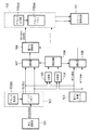
図1に、本発明の第1の実施形態の符号化装置の構成例を示す。本実施形態では 2係数ずつ処理する構成となっている。また、処理の流れは図12aから図12dのフローチャートに示すようになる。
【0024】
101 は直交変換器であり、符号化処理対象となる原画像を複数のブロック単位に分割したものを入力とし、該ブロック単位で直交変換を施し、直交変換係数を第1のスキャン変換器102へ順次出力する(S1201)。
【0025】
第1のスキャン変換器102は、直交変換器101より出力された直交変換係数を入力とし、予め定められたスキャン順序に並べ替え(S1202)、2係数ずつ出力する。また102は、例えば102(a)に示すブロックメモリと102(b)に示すアドレス生成器より構成され、102(a) は101より出力された直交変換係数を、一旦1ブロック分蓄え、102(b)の指示するアドレスに従って書込み及び読出しを行なう。102(b) は102(a)から直交変換係数を読出していったときに、予め定められたスキャン順で出力されるようにアドレスを生成する。実際のスキャン順序は前記直交変換ブロック単位内でなるべく有意係数が分散されるように考慮されたものが処理速度の観点から望ましく、例えば図2b に示したスキャン順、図2cに示したスキャン順、または図2d に示したスキャン順などが有利である。
【0026】
量子化閾値テーブル105は、予め所定のスキャン順序に対応するようにテーブル成分が並べ替えられており、102の出力する2つの直交変換係数にそれぞれ対応した量子化閾値を2つずつ出力する(S1204)。比較器103, 104 は102及び105より出力された直交変換係数と対応する量子化閾値の2組のペアをそれぞれ入力とし、直交変換係数と量子化閾値を比較して直交変換係数が量子化閾値より小さいか否かという比較結果情報をそれぞれ出力する(S1205)。この比較結果情報は、該直交変換係数を対応する量子化閾値で量子化した結果が0になるかどうかという情報と等価である。
【0027】
制御装置106は比較器103,104 の出力結果に応じて、102が出力する2つの直交変換係数の量子化結果の少なくともいずれか一方が0であれば(8−3)、量子化結果の0にならない方(有意係数)を選択するように、選択器107 及び選択器108に制御信号を出力し(両方共0の場合はいずれを選択するような制御信号を出力しても動作には影響しない)、いずれも0でないならば第1のスキャン変換器102で変換されたスキャン順になるように一つずつ2サイクルに分けて交互に選択するように制御信号を出力する。また制御装置106は比較器103,104 の出力結果に応じて、第2のスキャン変換器110にフォーマット信号を出力する。該フォーマット信号は、102が出力する2つの直交変換係数のうちいずれか一方が0であれば"0と有意係数のペア"、両方共0であれば"0と0のペア"、両方共有意係数であれば"一つの有意係数のみ"を示す情報(両方共有意係数の場合は、係数を一つずつ2サイクルに分けて量子化処理することになるので、2サイクル連続で"一つの有意係数のみ"を示す情報を出力することになる)を、ならびに"0と有意係数のペア"であるならば該0と有意係数のペアのうちどちらが第1のスキャン変換器102で変換されたスキャン順で先であるのかを示す情報を含む。
【0028】
このように、直交変換係数が0であれば量子化演算処理することなく結果が得られる(即ち0)ので、2つの直交変換係数のうち少なくともいずれか一方が0であれば、該2つの直交変換係数を実質的に1サイクルで量子化処理するように制御する。
【0029】
選択器107は102の出力する2つの直交変換係数のうちいずれか一方を、106の出力する制御信号に従って選択し、量子化演算器109へ出力する。
【0030】
選択器108は、105の出力する2つの量子化閾値のうちいずれか一方を、106の出力する制御信号に従って選択し、量子化演算器109へ出力する。また、選択器108の出力する量子化閾値は、常に選択器107の出力する直交変換係数に対応する量子化閾値となる。
【0031】
量子化演算器109は、107の出力を108の出力で除算して得る量子化結果を、第2のスキャン変換器110へ出力する。
【0032】
第2のスキャン変換器110は、106の出力するフォーマット信号に応じて、109の出力をジグザグスキャン順に並べ替え(S1219)、2つずつハフマン符号化器111へ出力する(S1220)。また110は、例えば110(a)に示すブロックメモリと110(b)に示すアドレス生成器より構成され、110(a) は109の出力を、一旦1ブロック分蓄え、110(b)の指示するアドレスに従って書込み及び読出しを行なう。110(b) は110(a)から直交変換係数を読出していったときに、ジグザグスキャン順で出力されるようにアドレスを生成する。
【0033】
ハフマン符号化器111は、110の出力を順次ハフマン符号化していく(S1221)。このように102より出力される2つの直交変換係数の量子化結果のうち、いずれか一方が0であれば該2つの係数を量子化するのに1サイクルの処理時間ですみ、いずれも0でないならばどちらも除算による量子化処理が必要となる為、該2つの係数を量子化するのに2サイクルの処理期間が必要となる。
【0034】
以下、例として102の出力する2つの直交変換係数を量子化閾値で量子化した結果を102の出力する順番に並べると、以下に示したようになる場合の処理を説明する。
【0035】
例:「0」は量子化結果が0、「有」は量子化結果が0でない(つまり有意係数)ことを示す。
【0036】
量子化結果:(0、有)、(0、0)、(有、0)、(有、有)
まず最初のペア(0、有)は一方が0で他方が有意係数であるので、制御装置106は選択器107,108に対し有意係数の方を選択するよう、制御信号を出力し(S1217)、また第2のスキャン変換器110には"0と有意係数のペア"という情報、ならびにそのどちらが第1のスキャン変換器102で変換されたスキャン順で先であるのかを示す情報を同時に出力する(S1216)。
【0037】
量子化演算器109は107より出力された有意係数を108の出力である量子化閾値で除算して得た量子化直交変換係数(有意係数)を第2のスキャン変換器110に出力する(S1218)。
【0038】
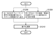
次のペア(0、0)は両方共0であるので、制御装置106は選択器107,108に対しいずれか一方(どちらでもよい)を選択するよう、制御信号を出力し(S1209)、また第2のスキャン変換器110には"0と0のペア"を示すフォーマット信号を同時に出力する(S1208)。
【0039】
量子化演算器109は107より出力された係数を108より出力された量子化閾値で除算して得た量子化直交変換係数(この場合結果的には無意係数になる)を第2のスキャン変換器110に出力する(S1210)。
【0040】
その次のペア(有、0)は一方が有意係数で他方が0であるので、制御装置106は選択器107,108に対し有意係数の方を選択するよう、制御信号を出力し(S1217)、また第2のスキャン変換器110には"0と有意係数のペア"という情報ならびにそのどちらが第1のスキャン変換器102で変換されたスキャン順で先であるのかを示す情報を同時に出力する(S1216)。
【0041】
量子化演算器109は107より出力された有意係数を108の出力である量子化閾値で除算して得た量子化直交変換係数(有意係数)を第2のスキャン変換器110に出力する(S1218)。
【0042】
その次のペア(有、有)は両方共0でないので、制御装置106は選択器107,108に対しまず最初のサイクルでは第1のスキャン変換器102で変換されたスキャン順で早い方を選択するよう、制御信号を出力し(S1212)、また第2のスキャン変換器110には"一つの有意係数のみ"という情報を同時に出力する(S1211)。その次のサイクルでは第1のスキャン変換器102で変換されたスキャン順で後の方を選択するよう、制御信号を出力し、また第2のスキャン変換器110には"一つの有意係数のみ"という情報を同時に出力する(S1214)。
【0043】
量子化演算器109は、2サイクルに分けて107より出力された係数及び108より出力された量子化閾値を用いて、2サイクルに分けて量子化演算し、その結果を量子化直交変換係数として2サイクルに分けて第2のスキャン変換器110に出力する(S1213、S1215)。
【0044】
このように、以上示した例では8個の係数の量子化処理を合計5サイクルで行なうことになる。
【0045】
[第2の実施形態]
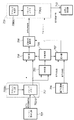
図3に、本発明の第2の実施形態の符号化装置の構成例を示す。
【0046】
301 は直交変換器であり、符号化処理対象となる原画像を複数のブロック単位に分割したものを入力とし、該ブロック単位で直交変換を施し、直交変換係数を第1のスキャン変換器302へ順次出力するとともに、該処理対象ブロックの周波数分布情報を順序選択信号生成器312へ出力する。順序選択信号生成器312は、301の出力する周波数分布情報をもとに第1のスキャン変換器302の備える複数のスキャン順序うちただ一つを選択する順序選択信号を出力する。
【0047】
例えば、図5(a)に示す量子化結果配列例のように、有意係数が上半分に偏っている場合、図2(a)から(d)に示すスキャン順序でスキャンすると、(有、有)の組み合わせの数は、それぞれ5、2、1、4となる。従って、第1のスキャン変換器302としては図2cに示すスキャン順序でスキャンすれば(有、有)の組み合わせの数が少なくなる。また、図6(a)に示す量子化結果配列例のように、有意係数が左半分に偏っている場合、図2(a)から(d)に示すスキャン順序でスキャンすると、(有、有)の組み合わせの数は、それぞれ5、2、4、1となる。従って、第1のスキャン変換器302としては図2dに示すスキャン順序でスキャンすれば(有、有)の組み合わせの数が少なくなる。このように、312は処理対象ブロックの周波数分布情報をもとに、処理速度的に有利となるスキャン順序を選択するよう、順序選択信号を生成していく。
【0048】
第1のスキャン変換器302は、直交変換器301より出力された直交変換係数を入力とし、予め備えた複数のスキャン順序のうち312より出力された順序選択信号に従って一つを選択し、該選択したスキャン順序に並べ替え、2係数ずつ出力する。また302は、302(a)に示すブロックメモリと、302(b)に示すアドレス生成器1、302(c)に示すアドレス生成器2、及び302(d)に示すアドレス生成器3と、312より出力された順序選択信号に従って302(b)、302(c)、302(d)の出力より一つを選択する選択器302(e)より構成される。302(a) は301より出力された直交変換係数を、一旦1ブロック分蓄え、302(e)の出力の指示するアドレスに従って書込み及び読出しを行なう。302(b) 、302(c)、302(d) はそれぞれ302(a)から直交変換係数を読出していったときに、例えば図2b に示したスキャン順、図2c に示したスキャン順、図2d に示したスキャン順のような予め定められたスキャン順で出力されるようにアドレスを生成する。
【0049】
量子化閾値テーブル305は、直交変換器312の出力する順序選択信号をもとに、302の出力する2つの直交変換係数にそれぞれ対応した量子化閾値を2つずつ出力する。
【0050】
比較器303, 304 は302及び305より出力された直交変換係数と対応する量子化閾値の2組のペアをそれぞれ入力とし、直交変換係数と量子化閾値を比較して直交変換係数が量子化閾値より小さいか否かという比較結果情報をそれぞれ出力する。この比較結果情報は、該直交変換係数を対応する量子化閾値で量子化した結果が0になるかどうかという情報と等価である。
【0051】
制御装置306は比較器303,304 の出力結果に応じて、302が出力する2つの直交変換係数の量子化結果の少なくともいずれか一方が0であれば、量子化結果の0にならない方を選択するように、選択器307 及び選択器308に制御信号を出力し(両方共0の場合はいずれを選択するような制御信号を出力しても動作には影響しない)、いずれも0でないならば第1のスキャン変換器302で選択されたスキャン順になるように2サイクルに分けて一つずつ交互に選択するように制御信号を出力する。また制御装置306は比較器303,304 の出力結果に応じて、第2のスキャン変換器310にフォーマット信号を出力する。該フォーマット信号は、302が出力する2つの直交変換係数のうちいずれか一方が0であれば"0と有意係数のペア"、両方共0であれば"0と0のペア"、両方共有意係数であれば"一つの有意係数のみ"を示す情報(両方共有意係数の場合は、係数を一つずつ2サイクルに分けて量子化処理することになるので、2サイクル連続で"一つの有意係数のみ"を示す情報を出力することになる)を、ならびに"0と有意係数のペア"であるならば該0と有意係数のペアのうちどちらが第1のスキャン変換器302で変換されたスキャン順で先であるのかを示す情報を含む。
【0052】
このように、直交変換係数が0であれば量子化演算処理することなく結果が得られる(即ち0)ので、2つの直交変換係数のうち少なくともいずれか一方が0であれば、該2つの直交変換係数を実質的に1サイクルで量子化処理するように制御する。
【0053】
選択器307は302の出力する2つの直交変換係数のうちいずれか一方を、306の出力する制御信号に従って選択し、量子化演算器309へ出力する。選択器308は、305の出力する2つの量子化閾値のうちいずれか一方を、306の出力する制御信号に従って選択し、量子化演算器309へ出力する。また、選択器308の出力する量子化閾値は、常に選択器307の出力する直交変換係数に対応する量子化閾値となる。
【0054】
量子化演算器309は、307の出力を308の出力で除算して得る量子化結果を、第2のスキャン変換器310へ出力する。
【0055】
第2のスキャン変換器310は、306の出力するフォーマット信号に応じて、直交変換器312の出力する順序選択信号をもとに、309の出力をジグザグスキャン順に並べ替え、2つずつハフマン符号化器311へ出力する。また310は、310(a)に示すブロックメモリと310(b)に示すアドレス生成器4、310(c)に示すアドレス生成器5、及び310(d)に示すアドレス生成器6と、301より出力された順序選択信号に従って310(b)、310(c)、310(d)の出力より一つを選択する選択器310(e)より構成される。310(a) は309の出力を、一旦1ブロック分蓄え、310(e)が出力するアドレスに従って書込み及び読出しを行なう。310(b) 、310(c)、310(d) はそれぞれ310(a)から量子化直交変換係数を読出していったときに、ジグザグスキャン順で出力されるようにアドレスを生成する。
【0056】
ハフマン符号化器311は、310の出力を順次ハフマン符号化していく。
【0057】
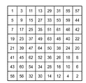
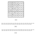
図4(a)に、8×8画素単位にブロック分割された画像に直交変換及び量子化を施した例を示す。図で「有」は有意係数、「0」は無意係数を表す。一般に多くの画像は直交変換を施した場合直流成分、低周波成分に電力が集中することが知られており、また量子化閾値は、人間の視覚特性が高周波成分に対し鈍感であることを考慮して、高周波成分に対応する量子化閾値に大きい値を割り当てることが多い。そのため、図4(a)に示すように、有意係数は直交変換ブロックの左上の方、つまりジグザグスキャン順で早い方に連続して集中する傾向にある。
【0058】
図4(a)の量子化結果配列例では、ジグザグスキャン順に2つずつ係数を取り出して並べると、図4(b)のようになる。この場合、(有、有)の組み合わせが7つあるので、64係数の量子化処理時間は7×2 + (32 - 7) = 39 サイクルとなる。即ち、図4(a)に示した例では従来例の構成では39サイクルの量子化処理時間を要する。
【0059】
これに対し、本発明の第1の実施形態の構成では量子化処理に要する処理時間は以下のようになる。
【0060】
まず、図2b に示したスキャン順を選択して図4(a)に示す量子化結果配列例を該スキャン順に2つずつ並べると、図4(c)のようになる。この場合、(有、有)の組み合わせが2つあるので、64係数の量子化処理時間は2×2 + (32 - 2) = 34 サイクルとなる。
【0061】
次に、図2c に示したスキャン順を選択して図4(a)に示す量子化結果配列例を該スキャン順に2つずつ並べると、図4(d)のようになる。この場合、(有、有)の組み合わせが1つあるので、64係数の量子化処理時間は1×2 + (32 - 1) = 33 サイクルとなる。
【0062】
次に、図2d に示したスキャン順を選択して図4(a)に示す量子化結果配列例を該スキャン順に2つずつ並べると、図4(e)のようになる。この場合、(有、有)の組み合わせが2つあるので、64係数の量子化処理時間は2×2 + (32 - 2) = 34 サイクルとなる。
【0063】
前記のように、従来のスキャン順に従った場合と、本発明におけるスキャン順に従った場合において、8x8のブロックにサイクル数の差は、図2b及び図2dに示したスキャン順を選択した場合は5サイクル、図2c に示したスキャン順を選択した場合は6サイクルである。これを画面全体(画素数Na)に換算すると以下の式によりサイクル数の差(D)を求めることができる。
【0064】
総画素数が200万ならば、D=(Na/64)x5 [サイクル]について、図2bに示したスキャン順を選択すれば、
D=200x106/64)x5=15.6x106[サイクル]
図2c に示したスキャン順を選択すれば、
D=200x106/64)x6=18.75x106[サイクル]となる。
【0065】
[第3の実施形態]
なお、上述した図2bから図2dに示した高周波成分と低周波成分とが入り組んだスキャン順を採用せず、図2eに示した様なラスタスキャン縦方向のスキャン順序、又はラスタスキャン順序を採用してもよい。以下、ラスタスキャン縦方向のスキャン順序を適用した場合を具体的に説明する。
【0066】
図14(a)は、8×8画素単位にブロック分割された画像に直交変換及び量子化を施した例である。図4(a)と同様、図14(a)においても、「有」は有意係数、「0」は無意係数を表す。
【0067】
図14(a)の例では、ジグザグスキャン順に2つずつ係数を取り出して並べると、図14bのようになる。この場合、(有、有)の組み合わせが9個あるので、64係数の量子化処理時間は9×2+(32-9)=41サイクルとなる。即ち、図14(a)に示した例(従来例の構成)では41サイクルの量子化処理時間を要する。
【0068】
これに対し、図2eに示したスキャン順を採用した場合、量子化処理に要する処理時間は以下のようになる。図2eに示したスキャン順を採用して図14(a)の例を該スキャン順に2つずつ並べると、図14cのようになる。この場合、(有、有)の組み合わせが6つあるので、64係数の量子化処理時間は6×2+(32-6)=38サイクルとなる。
【0069】
図15(a)に8×8画素単位にブロック分割された画像に直交変換及び量子化を施した別の例である。図4(a)と同様、図15(a)においても、「有」は有意係数、「0」は無意係数を表す。
【0070】
図15(a)の例では、ジグザグスキャン順に2つずつ係数を取り出して並べると、図15bのようになる。この場合、(有、有)の組み合わせが8個あるので、64係数の量子化処理時間は8×2+(32-8)=40サイクルとなる。即ち、図15(a)に示した例(従来例の構成)では40サイクルの量子化処理時間を要する。
【0071】
これに対し、図2eに示したスキャン順を採用した場合、量子化処理に要する処理時間は以下のようになる。図2eに示したスキャン順を選択して図15(a)の例を該スキャン順に2つずつ並べると、図15cのようになる。この場合、(有、有)の組み合わせが5つあるので、64係数の量子化処理時間は5×2+(32-5)=37サイクルとなる。
【0072】
以上のように、図2eに示すスキャン順を採用しても、サイクル数を十分に低減する効果を得ることが可能である。
【0073】
[第4の実施形態]
図7に本発明の第4の実施形態を示す。701はハフマン復号化器であり、ハフマン符号化された符号データを復号し、量子化された直交変換係数として第1のスキャン変換器702へ出力する(S1301)。
【0074】
第1のスキャン変換器702は、ハフマン復号器701より出力された量子化直交変換係数を入力とし、予め定められたスキャン順序に並べ替え(S1302)、2係数ずつ出力する(S1303)。また702は、例えば702(a)に示すブロックメモリと702(b)に示すアドレス生成器より構成され、702(a)は701より出力された量子化直交変換係数を、一旦1ブロック分蓄え、702(b)の指示するアドレスに従って書き込み及び読み出しを行なう。702(b)は702(a)から量子化直交変換係数を読み出していったときに、予め定められたスキャン順で出力されるようにアドレスを生成する。実際のスキャン順序は前記直交変換ブロック単位内でなるべく有意係数が分散されるように考慮されたものが処理速度の観点から望ましく、例えば図2bに記載のスキャン順、図2cに記載のスキャン順、または図2bに記載のスキャン順などが有利である。
【0075】
量子化閾値テーブル704は、702の出力する2つの量子化直交変換係数にそれぞれ対応した量子化閾値を2つずつ出力する(S1304)。
【0076】
0判定機703は702より出力された2つの量子化直交変換係数を入力とし、該入力された量子化直交変換係数がそれぞれ0であるか否か判定し、その判定結果を制御装置705に出力する(S1305)。
【0077】
制御装置705は0判定器703の出力結果に応じて、702が出力する2つの量子化直交変換係数のうちすくなくともいずれか一方が0であれば、0でない方(有意係数)を選択するように、選択器706及び選択器707に制御信号を出力し(両方共0の場合はいずれを選択するような制御信号を出力しても動作に影響しない)、いずれも0でないならば2サイクルに分けて第1のスキャン変換器702で出力されたスキャン順になるよう一つずつ交互に選択するように制御信号を出力する。また制御装置705は0判定器703の出力結果に応じて、第2のスキャン変換器709にフォーマット信号を出力する。該フォーマット信号は、702が出力する2つの量子化直交変換係数のうちいずれか一方が0であれば"0と有意係数のペア"、両方共0であれば"0と0のペア"、両方共有意係数であれば"一つの有意係数のみ"を示す情報(両方共有意係数の場合は、係数を一つずつ2サイクルに分けて逆量子化処理することになるので、2サイクル連続で"一つの有意係数のみ"を示す情報を出力することになる)を、ならびに"0と有意係数のペア"であるならば該0と有意係数のペアのうちどちらが第1のスキャン変換器702で変換されたスキャン順であるのかを示す情報を含む。
【0078】
このように、量子化直交変換係数が0であれば逆量子化演算処理することなく結果が得られる(即ち0)ので、2つの量子化直交変換係数のうち少なくともいずれか一方が0であれば、該2つの量子化直交変換係数を実質的に1サイクルで逆量子化するように制御する。
【0079】
選択器706は702の出力する2つの量子化直交変換係数のうちいずれか一方を、705の出力する制御信号に従って選択し、逆量子化演算器708へ出力する。選択器707は、704の出力する2つの量子化閾値のうちいずれか一方を、705の出力する制御信号に従って選択し、逆量子化演算器708へ出力する。また、選択器707の出力する量子化閾値は、常に選択器706の出力する量子化直交変換係数に対応する量子化閾値となる。
【0080】
逆量子化演算器708は、706の出力に707の出力を乗じて得る逆量子化結果を、第2のスキャン変換器709へ出力する。
【0081】
第2のスキャン変換器709は、制御装置705の出力するフォーマット信号に応じて、708の出力を予め定められたスキャン順に並べ替え(S1319)、2つずつ逆直交変換器710へ出力する(S1320)。また709は、例えば709(a)に示すブロックメモリと709(b)に示すアドレス生成器より構成され、709(a)は708の出力を一旦ブロック分蓄え、709(b)の指示するアドレスに従って書き込み及び読み出しを行なう。709(b)は709(a)から直交変換係数を読み出していったときに、予め定められたスキャン順で出力されるようにアドレスを生成する。第2のスキャン変換器709の施す実際のスキャン変換の順序は、逆直交変換器710の構成に応じて決定されるべきで、例えばラスタスキャン順、または縦方向のラスタスキャン順などが一般的であろう。
【0082】
逆直交変換器710は、709の出力に対し、順次逆直交変換処理を施して出力していく(S1321)。
【0083】
以上のような構成では、前述したような0判定器を設け、量子化直交変換係数の逆量子化結果が0になるのかどうかを逆量しか処理する前に知り、少なくともどちらか一方が0であるならば乗算処理をする必要がない為、他方の係数とあわせて2つの係数を1サイクルでただ一つの逆量子化演算器で逆量子化処理できることになる。
【0084】
例として、702の出力する2つの量子化直交変換係数が以下に示したようになる場合の処理を説明する。
【0085】
例:「0」は量子化直交変換係数が0、「有」は量子化直交変換係数が0でない(つまり有意係数)ことを示す。
【0086】
量子化直交変換係数:(0、有)、(0、0)、(有、0)、(有、有)
まず最初のペア(0、有)は一方が0で他方が有意係数であるので、制御装置705は選択器706,707に対し有意係数の方を選択するよう、制御信号を出力し(S1317)、また第2のスキャン変換器709には"0と有意係数のペア"という情報ならびに、そのどちらが第1のスキャン変換器702で変換されたスキャン順で先であるかを示す情報を同時に出力する(S1316)。
【0087】
逆量子化演算器708は706より出力された有意係数に707の出力である量子化閾値を乗じて得る直交変換係数(有意係数)を第2のスキャン変換器709に出力する(S1318)。
【0088】
次のペア(0、0)は両方共0であるので、制御装置705は選択器706,707に対しいずれか一方(どちらでもよい)を選択するよう、制御信号を出力し(S1314)、また第2のスキャン変換器709には"0と0のペア"という情報を同時に出力する(S1313)。
【0089】
逆量子化演算器708は706より出力された係数に707の出力である量子化閾値を乗じて得る直交変換係数(この場合結果的には無意係数になる)を第2のスキャン変換器709に同時に出力する(S1315)。
【0090】
その次のペア(有、0)は一方が有意係数で他方が0であるので、制御装置705は選択器706,707に対し有意係数の方を選択するよう、制御信号を出力し(S1317)、また第2のスキャン変換器709には"0と有意係数のペア"という情報ならびにそのどちらが第1のスキャン変換器702で変換されたスキャン順であるかを示す情報を同時に出力する(S1316)。
【0091】
逆量子化演算器708は706より出力された係数に707の出力である量子化閾値を乗じて得る直交変化係数(有意係数)を第2のスキャン変換器709に出力する(S1318)。
【0092】
その次のペア(有、有)は両方共0でないので、制御装置705は選択器706,707に対しまず最初のサイクルでは702で変換されたスキャン順で早い方を選択するよう、制御信号を出力し(S1308)、また第2のスキャン変換器709には"一つの有意係数のみ"という情報を同時に出力する(S1309)。その次のサイクルでは702で変換されたスキャン順で後の方を選択するよう、制御信号を出力し、また第2のスキャン変換器709には"一つの有意係数のみ"という情報を同時に出力する(S1311)。
【0093】
逆量子化演算器708は2サイクルに分けて706より出力された係数及び707より出力された量子化閾値を用いて、2サイクルに分けて逆量子化演算し、その結果を直交変換係数として2サイクルに分けて第2のスキャン変換器709に出力する(S1310、S1312)。
【0094】
このように、以上示した例では8個の係数の逆量子化処理を合計5サイクルで行うことができる。
【0095】
[第5の実施形態]
図8に本発明の第5の実施形態の復号化装置の構成例を示す。
【0096】
801はハフマン復号化器であり、ハフマン符号化された符号データを復号し、量子化された直交変換係数として第1のスキャン変換器802へ出力する。第1のスキャン変換器802は、ハフマン復号化器801より出力された量子化直交変換係数を入力とし、予め定められた複数のスキャン順序のうち予め定められた順序選択信号に従って一つを選択し、該選択したスキャン順序に並べ替え、2係数ずつ出力する。また802は、802(a)に示すブロックメモリと、802(b)に示すアドレス生成器1、802(c)に示すアドレス生成器2、及び802(d)に示すアドレス生成器3と、順序選択信号に従って802(b)、802(c)、802(d)の出力より一つを選択する選択器802(e)より構成される。802(a)は801より出力された量子化直交変換係数を、一旦1ブロック分蓄え、802(e)が出力するアドレスに従って書き込み及び読み出しを行なう。802(b)、802(c)、802(d)が備えるスキャン順序は、例えばそれぞれ図2bに記載のスキャン順、図2cに記載のスキャン順、図2dに記載のスキャン順、又は、図2eのスキャン順等が処理速度の観点から有利である。図2eは、ラスタスキャン縦方向のスキャン順序であるが、ラスタスキャン順序を採用してもよい。
【0097】
例えば、図10(a)に示す直交変換係数配列例のように、有意係数が上半分に偏っている場合、図2(a)から(e)に示すスキャン順序でスキャンすると、(有、有)の組み合わせの数は、それぞれ6、3、1、5、6となる。従って、図2cに示すスキャン順序で書込み読出しを行えば(有、有)の組み合わせの数が少なくなる。また、図11(a)に示す量子化結果配列例のように、有意係数が左半分に偏っている場合、図2(a)から(e)に示すスキャン順序でスキャンすると、(有、有)の組み合わせの数は、それぞれ5、2、4、1、6となる。従って、図2dに示すスキャン順序で書込み読出しを行えば(有、有)の組み合わせの数が少なくなる。このように、処理対象ブロックの有意係数分布情報をもとに処理速度的に有利となるスキャン順序が選択される。
【0098】
量子化閾値テーブル804は、順次選択信号をもとに、802の出力する2つの量子化直交変換数にそれぞれ対応した量子化閾値を2つずつ出力する。0判定器803は802より出力された2つの量子化直交変換係数を入力とし、該入力された量子化直交変換係数がそれぞれ0であるか否か判定し、その判定結果を制御装置805に出力する。
【0099】
制御措置805は0判定器803の出力結果に応じて、802が出力する2つの量子化直交変換係数のうち少なくともいずれか一方が0であれば、0でない方を選択するように、選択器806及び選択器807に制御信号を出力し(両方共0の場合はいずれを選択するような制御信号を出力しても影響しない)、いずれも0でないならば2サイクルに分けて第1のスキャン変換器802で変換されたスキャン順になるように一つずつ交互に選択するように制御信号を出力する。また制御装置805は0判定器803の出力結果に応じて、第2のスキャン変換器809にフォーマット信号を出力する。該フォーマット信号は、802が出力する2つの量子化直交変換係数のうちいずれか一方が0であれば"0と有意係数のペア"、両方共0であれば"0と0のペア"、両方共有意係数であれば"一つの有意係数のみ"を示す情報(両方共有意係数の場合は、係数を一つずつ2サイクルに分けて逆量子化処理することになるので、2サイクル連続で"一つの有意係数のみ"を示す情報を出力することになる)を、ならびに"0と有意係数のペア"であるならば該0と有意係数のペアのうちどちらが第1のスキャン変換器802で変換されたスキャン順で先であるのかを示す情報を含む。
【0100】
このように、量子化直交変換係数が0であれば逆量子化演算処理することなく結果が得られる(即ち0)ので、2つの量子化直交変換係数のうち少なくともいずれか一方が0であれば、該2つの量子化直交変換係数を実質的に1サイクルで逆量子化するように制御する。
【0101】
選択器806は802の出力する2つの量子化直交変換係数のうちいずれか一方を、805の出力する制御信号に従って選択し、逆量子化演算器808へ出力する。選択器807は、804の出力する2つの量子化閾値のうちいずれか一方を、805の出力する制御信号に従って選択し、逆量子化演算器808へ出力する。また、選択器807の出力する量子化閾値は、常に選択器806の出力する量子化直交変換係数に対応する量子化閾値となる。
【0102】
逆量子化演算器808は、806の出力に807の出力を乗じて得る逆量子化結果を、第2のスキャン変換器809に出力する。
【0103】
第2のスキャン変換器809は、順序選択信号をもとに802で選択されたスキャン順序に対応するスキャン順序を選択し、該選択されたスキャン順序に従って808の出力を並べ替え、2つずつ逆直交変換器810へ出力する。また1809は、809(a)に示すブロックメモリと809(b)に示すアドレス生成器4、809に示すアドレス生成器5、及び809(d)に示すアドレス生成器6と、順序選択信号に従って809(b)、809(d)の出力により一つを選択する選択器809(e)より構成される。809(a)は808の出力を一旦1ブロック分蓄え、809(e)の出力するアドレスに従って書き込み及び読み出しを行なう。逆直交変換器810は、809の出力を順次逆直交変換処理していく。
【0104】
図9(a)に、8×8画素単位にブロック分割された画像に直交変換及び量子化を施した例を示す。図で「有」は有意係数、「0」は無意係数を表す。
【0105】
一般に多くの画像は直交変換を施した場合直流成分、低周波成分に電力が集中することが知られており、また量子化閾値は、人間の視覚特性が高周波成分に対し鈍感であることを考慮して、高周波成分に対応する量子化閾値に大きい値を割り当てることが多い。その為図9(a)に示すように、有意係数は直交変換ブロックの左上の方、つまりジグザグスキャン順で早い方に連続して集中する傾向にある。この特性を利用して、該有意係数が直交変換ブロック内でなるべく均等に分散されるように考慮してスキャン順を定めることにより、量子化処理時間を最小限に押さえることができる。
【0106】
図9(a)に示された例において、本発明の第4の実施形態の構成では、処理に要するサイクルの数は以下のようになる。
【0107】
まず、図2b に示したスキャン順を選択して図9(a)の例を該スキャン順に2つずつ並べると、図9(c)のようになる。この場合、(有、有)の組み合わせが2つあるので、64係数の量子化処理時間は2×2 + (32 - 2) = 34 サイクルとなる。
【0108】
図2c に示したスキャン順を選択して図9(a)の例を該スキャン順に2つずつ並べると、図9(d)のようになる。この場合、(有、有)の組み合わせが1つあるので、64係数の量子化処理時間は1×2 + (32 - 1) = 33 サイクルとなる。
【0109】
次に、図2d に示したスキャン順を選択して図9(a)の例を該スキャン順に2つずつ並べると、図9(e)のようになる。この場合、(有、有)の組み合わせが3つあるので、64係数の量子化処理時間は3×2 + (32 - 3) = 35 サイクルとなる。
【0110】
次に、図2e に示したスキャン順を選択して図9(a)の例を該スキャン順に2つずつ並べると、図9(f)のようになる。この場合、(有、有)の組み合わせが7つあるので、64係数の量子化処理時間は7×2 + (32 - 7) = 39 サイクルとなる。
【0111】
従って、ブロックメモリ709(a)への書込みサイクルは図2cの場合は33サイクルとなる。また、ブロックメモリ709(a)からの読出しサイクルは8×8÷2=32サイクルであり、初期化処理サイクルは必要ないので、全体としての処理サイクルは最小で33+32=65サイクルとなる。
【0112】
一方、図9(a)に示された例において、従来例の構成では処理に要するサイクル数は以下のようになる。
【0113】
図9(a)に示された例では、有意係数の個数は20個であるので、該処理対象ブロックの処理に要する総クロックサイクル数は、書き込み処理=20サイクル、読出し処理32サイクル、初期化処理=20サイクルであるので、合計して72サイクルとなる。
【0114】
従って、図9(a)に示された例においては、従来より約10%程度処理時間が短縮されたこととなる。又、従来の構成では、8×8の単位ブロック当たりに要する処理サイクル数は32〜160サイクルと非常に大きい開きがあり、そのため圧縮率の高い符号データと圧縮率の低い符号データとで復号化勝利に要する時間の差が大きくなってしまうという問題があったのに対し、本発明の構成を備えた本実施形態では、8×8の単位ブロック当たりに要する処理サイクル数は64〜96サイクルと開きが小さく、従って、圧縮率の高い符号データと圧縮率の低い符号データとで復号化処理に要する時間の差が小さいという効果がある。この事実は、復号化装置を組み込むシステムが復号化装置に要求する処理速度として、その復号化装置の持つ処理速度の最悪値に合わせなければならない場合などに効果的であり、また復号化装置を組み込むシステムが扱う画像符号データが、比較的圧縮率の低いものが多い場合などにも有効である。
【0115】
以上示したように、ブロックメモリの初期化処理期間を省き、逆量子化器に投入する量子化直交変換係数の有意係数がなるべく均等に分散されるようにスキャン順を考慮することにより、画像の圧縮率に拘わらず高速に復号化処理を行うことができる。
【0116】
[他の実施形態]
なお、本発明は、複数の機器(例えばホストコンピュータ、インタフェイス機器、リーダ、プリンタなど)から構成されるシステムに適用しても、一つの機器からなる装置(例えば、複写機、ファクシミリ装置など)に適用してもよい。
【0117】
また、本発明の目的は、前述した実施形態の機能を実現するソフトウェアのプログラムコードを記録した記憶媒体(または記録媒体)を、システムあるいは装置に供給し、そのシステムあるいは装置のコンピュータ(またはCPUやMPU)が記憶媒体に格納されたプログラムコードを読み出し実行することによっても、達成されることは言うまでもない。この場合、記憶媒体から読み出されたプログラムコード自体が前述した実施形態の機能を実現することになり、そのプログラムコードを記憶した記憶媒体は本発明を構成することになる。また、コンピュータが読み出したプログラムコードを実行することにより、前述した実施形態の機能が実現されるだけでなく、そのプログラムコードの指示に基づき、コンピュータ上で稼働しているオペレーティングシステム(OS)などが実際の処理の一部または全部を行い、その処理によって前述した実施形態の機能が実現される場合も含まれることは言うまでもない。
【0118】
さらに、記憶媒体から読み出されたプログラムコードが、コンピュータに挿入された機能拡張カードやコンピュータに接続された機能拡張ユニットに備わるメモリに書込まれた後、そのプログラムコードの指示に基づき、その機能拡張カードや機能拡張ユニットに備わるCPUなどが実際の処理の一部または全部を行い、その処理によって前述した実施形態の機能が実現される場合も含まれることは言うまでもない。
【0119】
【発明の効果】
以上示したように、本発明により量子化又は逆量子化される係数のうち、有意のものがなるべく均等に分散されるように考慮したスキャン順序を採用することにより、ジグザクスキャン順で処理する場合よりも、処理サイクルを低減でき、全体として高速に符号化処理を行なうことが可能となる。
【0120】
また、予め複数のスキャン順序を用意し、これを順序選択信号によって切替えて使用することで、入力係数の分布に適応したスキャン順序を選択することが可能となり、処理サイクルをより効果的に低減できる。
【図面の簡単な説明】
【図1】本発明の第1の実施形態の構成図である。
【図2a】ジグザグスキャン順序を示す図である。
【図2b】本発明におけるスキャン順序の一つを示す図である。
【図2c】本発明におけるスキャン順序の一つを示す図である。
【図2d】本発明におけるスキャン順序の一つを示す図である。
【図2e】本発明におけるスキャン順序の一つを示す図である。
【図3】本発明の第2の実施形態の構成を示す図である。
【図4】8x8ブロックの量子化結果例、及び、それについて図2(a)乃至(d)に示すスキャン順序で2個ずつ配列した場合の組合せを示す図である。
【図5】8x8ブロックの量子化結果例、及び、それについて図2(a)乃至(d)に示すスキャン順序で2個ずつ配列した場合の組合せを示す図である。
【図6】8x8ブロックの量子化結果例、及び、それについて図2(a)乃至(d)に示すスキャン順序で2個ずつ配列した場合の組合せを示す図である。
【図7】本発明の第4の実施形態の構成を示す図である。
【図8】本発明の第5の実施形態の構成を示す図である。
【図9】8x8ブロックの直交変換係数配列例、及び、それについて図2(a)乃至(d)に示すスキャン順序で2個ずつ配列した場合の組合せを示す図である。
【図10】8x8ブロックの直交変換係数配列例、及び、それについて図2(a)乃至(d)に示すスキャン順序で2個ずつ配列した場合の組合せを示す図である。
【図11】8x8ブロックの直交変換係数配列例、及び、それについて図2(a)乃至(d)に示すスキャン順序で2個ずつ配列した場合の組合せを示す図である。
【図12a】本発明の第1の実施形態における、処理の流れを示したフローチャートである。
【図12b】本発明の第1の実施形態における、処理の流れを示したフローチャートである。
【図12c】本発明の第1の実施形態における、処理の流れを示したフローチャートである。
【図12d】本発明の第1の実施形態における、処理の流れを示したフローチャートである。
【図13a】本発明の第4の実施形態における、処理の流れを示したフローチャートである。
【図13b】本発明の第4の実施形態における、処理の流れを示したフローチャートである。
【図13c】本発明の第4の実施形態における、処理の流れを示したフローチャートである。
【図13d】本発明の第4の実施形態における、処理の流れを示したフローチャートである。
【図14】8x8ブロックの量子化結果例、及び、それについて図2(a)又は(e)に示すスキャン順序で2個ずつ配列した場合の組合せを示す図である。
【図15】8x8ブロックの量子化結果例、及び、それについて図2(a)又は(e)に示すスキャン順序で2個ずつ配列した場合の組合せを示す図である。
【図16】8x8ブロックの量子化結果例、及び、それについて図2(a)又は(e)に示すスキャン順序で2個ずつ配列した場合の組合せを示す図である。[0001]
BACKGROUND OF THE INVENTION
The present invention Coding The present invention relates to an apparatus, a method, and a program for performing the above.
[0002]
[Prior art]
As a multi-value image compression technique, there is conventionally known a technique in which an original image is divided into block units composed of a plurality of pixels, subjected to orthogonal transformation, quantized with a specified quantization threshold value, and Huffman encoded. Such encoding processing is also adopted in the JPEG (Joint Photographic Experts Group) system, and apparatuses for encoding and decoding the hardware by using it as hardware have been conventionally known.
[0003]
For example, in a hardware coding apparatus, conventionally, a device for obtaining a good processing rate with a minimum circuit scale for quantization processing has been devised, and there are a plurality of orthogonal transform coefficients converted in zigzag scan order. Processed one by one. Therefore, the configuration of a conventional encoding device will be described below.
[0004]
A conventional encoding device performs orthogonal transform on an input original image divided into a plurality of blocks by an orthogonal transformer, and outputs orthogonal transform coefficients. The outputted coefficients are rearranged in the zigzag scan order by the zigzag scan converter, and are output to the comparator by two coefficients, and the corresponding quantization thresholds are also output to the comparator two by two. The comparator compares the output coefficient with the corresponding quantization threshold and outputs comparison result information indicating whether the orthogonal transform coefficient is smaller than the quantization threshold. This comparison result information is equivalent to information indicating whether or not the result of quantizing the orthogonal transform coefficient with the corresponding quantization threshold is zero.
[0005]
In the control device, according to the output result of the comparator, if at least one of the quantization results of the two orthogonal transform coefficients is 0, the one that does not become 0 (significant coefficient) of the quantization result is selected. A control signal is output to the selector (if both are 0, a control signal that selects which one is output does not affect the operation), and if neither is 0, one is arranged in zigzag scan order. A control signal is output so as to be alternately selected in two cycles. The control device outputs a format signal to the Huffman encoder according to the output result of the comparator. The format signal is “a pair of 0 and a significant coefficient” if one of the two orthogonal transform coefficients is 0, “a pair of 0 and 0” if both are 0, and if both are a shared coefficient. Information indicating "only one significant coefficient" (In the case of both shared coefficients, the coefficient is divided into two cycles one by one, so the quantization process is performed for two consecutive cycles. And information indicating which one of the 0 and significant coefficient pair is first in the zigzag scan order is included.
[0006]
Thus, if the orthogonal transform coefficient is 0, the result is obtained without performing the quantization process (that is, 0). Therefore, if at least one of the two orthogonal transform coefficients is 0, the two orthogonal transforms The coefficient is controlled to be quantized in substantially one cycle. However, if both of the two coefficients are significant as a result of the comparison, neither coefficient is 0 and a quantization process is required, which requires a two-cycle processing period.
[0007]
In addition, in a hardware decoding apparatus, a device for obtaining a good processing rate with a minimum circuit scale for inverse quantization processing has been conventionally made. For example, a significant coefficient among quantized orthogonal transform coefficients is used. A proposal has been made to perform the initialization operation of the memory by performing the inverse quantization operation and writing to the memory only for the memory. The configuration of the conventional decoding device will be described below.
[0008]
The conventional decoder uses the Huffman decoder to decode the Huffman-encoded code data, and outputs zero-run information indicating the quantized orthogonal transform coefficient and how many 0s previously existed. The output quantized orthogonal transform coefficient is input to the inverse quantizer and subjected to inverse quantization processing using the quantization threshold corresponding to the quantized orthogonal transform coefficient output from the quantization threshold table, and the orthogonal transform coefficient Is output to the selector.
[0009]
The address generator calculates which position in the orthogonal transform processing unit block the output quantized orthogonal transform coefficient corresponds to from the output zero-run information, and the block memory write address and quantization corresponding to the corresponding position Each of the threshold table read addresses is output, and for each unit block, an initialization target address for initializing the block memory prior to the quantization process is output to the block memory, indicating that the initialization operation is in progress. Is output to the control device. In the initialization process, 0 is written in advance before the processing of the unit block, the orthogonal transform coefficient written to the block memory in the actual processing stage is limited to only a significant coefficient (non-zero coefficient), and an insignificant coefficient (0 This is a pre-process for omitting the writing process of the coefficient. In this case, it is only necessary to initialize the address where the significant coefficient is written. For this purpose, it is necessary to store the address where the significant coefficient is written, and the write address for initialization is stored in the memory. Generated based on the stored address information.
[0010]
The quantization threshold table reads the quantization threshold corresponding to the quantization orthogonal transform coefficient to be processed based on the output of the write address generator, and outputs it to the inverse quantizer. Based on the signal indicating that the initialization operation is being performed, the control device outputs an order selection signal indicating whether or not to select the
[0011]
Based on the write / read control output from the control device, the read address generator addresses the unit orthogonal transform processing block data written in the block memory during the read period so as to sequentially read the data in the zigzag scan order. Is output to the block memory.
[0012]
The block memory operates in a cycle of initialization, writing, and reading in the zigzag scan order for each orthogonal transform processing unit block. The block memory writes the output of the selector to the write address, and the read is performed according to the write / read control signal output from the control device according to the read address. The read value is output to the inverse orthogonal transformer.
[0013]
The inverse orthogonal transformer sequentially performs inverse orthogonal transform on the orthogonal transform coefficients output from the block memory in the zigzag scan order, and outputs a conversion result for each unit block.
[0014]
In the configuration as described above, the writing process to the block memory requires clock cycles corresponding to the number of significant coefficients existing in the unit block, and reading is performed by reading two coefficients, so the number of samples in the unit block is 64. Then, 32 clock cycles are required, and initialization requires clock cycles corresponding to the number of significant coefficients existing in the unit block.
[0015]
For example, assuming that the number of samples in a unit block is 64 and there are 20 significant coefficients in the unit block to be processed, the total number of clock cycles required for processing of the processing target block is write processing = 20 cycles. Since the read process = 32 cycles and the initialization process = 20 cycles, the total is 72 clock cycles.
[0016]
Further, the minimum value of the number of clock cycles required to process a unit orthogonal transform block (8 × 8 = 64 samples) is when the number of significant coefficients in the processing target block is 0. Since the number of clock cycles is write processing = 0 cycles, read processing = 32 cycles, and initialization processing = 0 cycles, the total number of clock cycles is 32 cycles. On the other hand, the maximum number of clock cycles required to process a unit orthogonal transform block is when the number of significant coefficients in the processing target block is 64, and the number of clock cycles at that time is Since the write process = 64 cycles, the read process = 32 cycles, and the initialization process = 64 cycles, the total is 160 cycles.
[0017]
[Problems to be solved by the invention]
In the configuration of the conventional coding apparatus, it is desirable from the viewpoint of processing speed that the quantization result of at least one of the two orthogonal transform coefficient pairs input to the comparison means is zero. For this purpose, it is desirable that the quantized orthogonal transform coefficients in the orthogonal transform block are input to the comparison unit with significant coefficients dispersed as much as possible, but if they are input in the zigzag scan order. There is a problem that the encoding processing speed does not increase because significant coefficients tend to be arranged in a concentrated manner.
[0019]
[Means for Solving the Problems]
In view of the above problems, the present invention provides the following means in order to increase encoding efficiency.
[0020]
An image encoding device that compares a plurality of n orthogonal transform coefficients with the same number of quantization thresholds and selectively quantizes and encodes the orthogonal transform coefficients based on a comparison result, wherein the orthogonal transform coefficients are , First scan conversion means for rearranging in the first scan order and outputting n pieces each, Quantities that compare each of the n orthogonal transform coefficients output from the first scan conversion means with n quantization thresholds and selectively quantize and output the orthogonal transform coefficients based on the comparison result. And means for outputting the quantization means A second scan conversion means for outputting the quantized orthogonal transform coefficients in a zigzag scan order; and Encoding means for encoding the quantized orthogonal transform coefficient output from the second scan conversion means, wherein the first scan order is such that the comparison result in the quantization means is significant. The scan order is such that the transform coefficients are distributed among the n output units. Thus, the overall processing rate is improved by arranging the significant coefficients in an order that is dispersed and arranged as much as possible.
[0023]
DETAILED DESCRIPTION OF THE INVENTION
[First embodiment]
FIG. 1 shows a configuration example of an encoding apparatus according to the first embodiment of the present invention. In this embodiment, it is configured to process two coefficients. The processing flow is as shown in the flowcharts of FIGS. 12a to 12d.
[0024]
[0025]
The
[0026]
In the quantization threshold table 105, table components are rearranged in advance so as to correspond to a predetermined scan order, and two quantization thresholds respectively corresponding to the two orthogonal transform coefficients output by the 102 are output (S1204). ).
[0027]
If at least one of the quantization results of the two orthogonal transform coefficients output from 102 is 0 according to the output results of the
[0028]
Thus, if the orthogonal transform coefficient is 0, the result is obtained without performing the quantization operation processing (that is, 0). Therefore, if at least one of the two orthogonal transform coefficients is 0, the two orthogonal transform coefficients are obtained. Control is performed so that the transform coefficient is substantially quantized in one cycle.
[0029]
The
[0030]
The
[0031]
The
[0032]
The
[0033]
The Huffman encoder 111 sequentially encodes the output of 110 (S1221). In this way, if one of the two orthogonal transform coefficients output from 102 is 0, the processing time of one cycle is sufficient to quantize the two coefficients, and neither of them is 0. Then, since both require quantization processing by division, a processing period of 2 cycles is required to quantize the two coefficients.
[0034]
Hereinafter, as an example, when the results of quantizing the two orthogonal transform coefficients output by 102 with the quantization threshold are arranged in the output order of 102, processing in the case shown below will be described.
[0035]
Example: “0” indicates that the quantization result is 0, and “present” indicates that the quantization result is not 0 (that is, a significant coefficient).
[0036]
Quantization result: (0, yes), (0, 0), (yes, 0), (yes, yes)
First, since one of the first pairs (0, yes) is 0 and the other is a significant coefficient, the
[0037]
The
[0038]
Since both of the next pair (0, 0) are 0, the
[0039]
The
[0040]
Since one of the next pair (existing, 0) is a significant coefficient and the other is 0, the
[0041]
The
[0042]
Since both of the next pairs (Yes, Yes) are not 0, the
[0043]
The
[0044]
Thus, in the example shown above, the quantization processing of 8 coefficients is performed in a total of 5 cycles.
[0045]
[Second Embodiment]
FIG. 3 shows a configuration example of an encoding apparatus according to the second embodiment of the present invention.
[0046]
[0047]
For example, if the significant coefficient is biased to the upper half as in the quantization result array example shown in FIG. 5A, scanning in the scan order shown in FIGS. ) Are 5, 2, 1, 4 respectively. Therefore, if the
[0048]
The
[0049]
The quantization threshold table 305 outputs two quantization thresholds respectively corresponding to the two orthogonal transform coefficients output from 302 based on the order selection signal output from the orthogonal transformer 312.
[0050]
[0051]
The
[0052]
Thus, if the orthogonal transform coefficient is 0, the result is obtained without performing the quantization operation processing (that is, 0). Therefore, if at least one of the two orthogonal transform coefficients is 0, the two orthogonal transform coefficients are obtained. Control is performed so that the transform coefficient is substantially quantized in one cycle.
[0053]
The
[0054]
The
[0055]
The
[0056]
The Huffman encoder 311 sequentially encodes the output of 310.
[0057]
FIG. 4A shows an example in which orthogonal transformation and quantization are performed on an image divided into blocks of 8 × 8 pixels. In the figure, “present” represents a significant coefficient, and “0” represents an insignificant coefficient. In general, many images are known to concentrate power on DC and low-frequency components when orthogonal transformation is applied, and the quantization threshold takes into account that human visual characteristics are insensitive to high-frequency components. Thus, a large value is often assigned to the quantization threshold corresponding to the high frequency component. For this reason, as shown in FIG. 4A, the significant coefficients tend to continuously concentrate on the upper left side of the orthogonal transform block, that is, the earlier one in the zigzag scan order.
[0058]
In the quantization result arrangement example of FIG. 4A, when two coefficients are extracted and arranged in the zigzag scan order, the result is as shown in FIG. 4B. In this case, since there are seven combinations (Yes, Yes), the 64 coefficient quantization processing time is 7 × 2 + (32 −7) = 39 cycles. That is, in the example shown in FIG. 4A, the conventional configuration requires 39 cycles of quantization processing time.
[0059]
On the other hand, in the configuration of the first embodiment of the present invention, the processing time required for the quantization processing is as follows.
[0060]
First, when the scan order shown in FIG. 2b is selected and the quantization result array example shown in FIG. 4 (a) is arranged two by two in the scan order, FIG. 4 (c) is obtained. In this case, since there are two combinations (Yes, Yes), the 64 coefficient quantization processing time is 2 × 2 + (32 −2) = 34 cycles.
[0061]
Next, when the scan order shown in FIG. 2c is selected and the quantization result array example shown in FIG. 4 (a) is arranged two by two in the scan order, FIG. 4 (d) is obtained. In this case, since there is one combination (Yes, Yes), the 64 coefficient quantization processing time is 1 × 2 + (32-1) = 33 cycles.
[0062]
Next, when the scan order shown in FIG. 2d is selected and the quantization result array example shown in FIG. 4A is arranged two by two in the scan order, FIG. 4E is obtained. In this case, since there are two combinations (Yes, Yes), the 64 coefficient quantization processing time is 2 × 2 + (32 −2) = 34 cycles.
[0063]
As described above, when the conventional scan order is followed and when the scan order according to the present invention is followed, the difference in the number of cycles for the 8 × 8 block is 5 when the scan order shown in FIGS. 2b and 2d is selected. 6 cycles when the scan order shown in FIG. 2c is selected. When this is converted into the entire screen (number of pixels Na), the difference (D) in the number of cycles can be obtained by the following equation.
[0064]
If the total number of pixels is 2,000,000, if the scan order shown in FIG. 2b is selected for D = (Na / 64) × 5 [cycle],
D = 200x10 6 /64)x5=15.6x10 6 [cycle]
If you select the scan order shown in Figure 2c,
D = 200x10 6 /64)x6=18.75x10 6 [Cycle].
[0065]
[Third embodiment]
Note that the scan order in which the high frequency component and the low frequency component shown in FIGS. 2b to 2d are complicated is not adopted, and the raster scan vertical scan order or the raster scan order as shown in FIG. 2e is adopted. May be. Hereinafter, the case where the scan order in the raster scan vertical direction is applied will be specifically described.
[0066]
FIG. 14A shows an example in which orthogonal transformation and quantization are performed on an image divided into blocks of 8 × 8 pixels. Similarly to FIG. 4A, in FIG. 14A, “present” represents a significant coefficient and “0” represents an insignificant coefficient.
[0067]
In the example of FIG. 14A, when two coefficients are extracted and arranged in the zigzag scan order, the result is as shown in FIG. 14b. In this case, since there are nine combinations (Yes, Yes), the 64 coefficient quantization processing time is 9 × 2 + (32−9) = 41 cycles. That is, the example shown in FIG. 14A (configuration of the conventional example) requires 41 cycles of quantization processing time.
[0068]
On the other hand, when the scan order shown in FIG. 2e is adopted, the processing time required for the quantization processing is as follows. When the scan order shown in FIG. 2E is adopted and the example of FIG. 14A is arranged two by two in the scan order, the result is as shown in FIG. 14C. In this case, since there are six combinations of (Yes, Yes), the 64 coefficient quantization processing time is 6 × 2 + (32−6) = 38 cycles.
[0069]
FIG. 15A shows another example in which orthogonal transformation and quantization are performed on an image divided into blocks of 8 × 8 pixels. As in FIG. 4A, in FIG. 15A, “present” represents a significant coefficient, and “0” represents an insignificant coefficient.
[0070]
In the example of FIG. 15A, when two coefficients are extracted and arranged in the zigzag scan order, the result is as shown in FIG. 15b. In this case, since there are eight combinations (Yes, Yes), the 64 coefficient quantization processing time is 8 × 2 + (32−8) = 40 cycles. That is, the example shown in FIG. 15A (configuration of the conventional example) requires 40 cycles of quantization processing time.
[0071]
On the other hand, when the scan order shown in FIG. 2e is adopted, the processing time required for the quantization processing is as follows. When the scan order shown in FIG. 2e is selected and the example of FIG. 15A is arranged two by two in the scan order, the result is as shown in FIG. 15c. In this case, since there are five (Yes, Yes) combinations, the 64 coefficient quantization processing time is 5 × 2 + (32−5) = 37 cycles.
[0072]
As described above, even if the scan order shown in FIG. 2e is adopted, it is possible to obtain the effect of sufficiently reducing the number of cycles.
[0073]
[Fourth Embodiment]
FIG. 7 shows a fourth embodiment of the present invention.
[0074]
The
[0075]
The quantization threshold table 704 outputs two quantization thresholds respectively corresponding to the two quantized orthogonal transform coefficients output from 702 (S1304).
[0076]
The 0
[0077]
The
[0078]
Thus, if the quantized orthogonal transform coefficient is 0, the result is obtained without performing the inverse quantization operation processing (that is, 0). Therefore, if at least one of the two quantized orthogonal transform coefficients is 0, The two quantized orthogonal transform coefficients are controlled to be inversely quantized substantially in one cycle.
[0079]
The
[0080]
The
[0081]
The
[0082]
The inverse
[0083]
In the configuration as described above, the 0 decision unit as described above is provided, and it is known whether or not the inverse quantization result of the quantized orthogonal transform coefficient is 0 before processing only the inverse amount, and at least one of them is 0. If there is, it is not necessary to perform multiplication processing, and therefore, the two coefficients together with the other coefficient can be inversely quantized by a single inverse quantization computing unit in one cycle.
[0084]
As an example, a process when the two quantized orthogonal transform coefficients output from 702 are as shown below will be described.
[0085]
Example: “0” indicates that the quantized orthogonal transform coefficient is 0, and “present” indicates that the quantized orthogonal transform coefficient is not 0 (that is, a significant coefficient).
[0086]
Quantized orthogonal transform coefficients: (0, yes), (0, 0), (yes, 0), (yes, yes)
Since the first pair (0, yes) is one and the other is a significant coefficient, the
[0087]
The
[0088]
Since both of the next pairs (0, 0) are 0, the
[0089]
The inverse
[0090]
Since one of the next pair (existing, 0) is a significant coefficient and the other is 0, the
[0091]
The
[0092]
Since the next pair (yes / no) is not 0, the
[0093]
The inverse
[0094]
As described above, in the example described above, the inverse quantization processing of eight coefficients can be performed in a total of five cycles.
[0095]
[Fifth Embodiment]
FIG. 8 shows a configuration example of a decoding apparatus according to the fifth embodiment of the present invention.
[0096]
[0097]
For example, when the significant coefficients are biased to the upper half as in the orthogonal transform coefficient array example shown in FIG. 10A, scanning in the scan order shown in FIGS. ) Are 6, 3, 1, 5, 6 respectively. Therefore, if writing and reading are performed in the scan order shown in FIG. 2c, the number of combinations (Yes, Yes) is reduced. If the significant coefficient is biased to the left half as in the example of the quantization result array shown in FIG. 11A, scanning with the scan order shown in FIGS. ) Are 5, 2, 4, 1, 6 respectively. Therefore, if writing and reading are performed in the scan order shown in FIG. 2d, the number of combinations (Yes, Yes) is reduced. In this way, a scan order that is advantageous in terms of processing speed is selected based on the significant coefficient distribution information of the processing target block.
[0098]
The quantization threshold value table 804 outputs two quantization threshold values respectively corresponding to the two quantization orthogonal transform numbers output by the
[0099]
The
[0100]
Thus, if the quantized orthogonal transform coefficient is 0, the result is obtained without performing the inverse quantization operation processing (that is, 0). Therefore, if at least one of the two quantized orthogonal transform coefficients is 0, The two quantized orthogonal transform coefficients are controlled to be inversely quantized substantially in one cycle.
[0101]
A
[0102]
The
[0103]
The
[0104]
FIG. 9A shows an example in which orthogonal transformation and quantization are performed on an image divided into blocks of 8 × 8 pixels. In the figure, “present” represents a significant coefficient, and “0” represents an insignificant coefficient.
[0105]
In general, many images are known to concentrate power on DC and low-frequency components when orthogonal transformation is applied, and the quantization threshold takes into account that human visual characteristics are insensitive to high-frequency components. Thus, a large value is often assigned to the quantization threshold corresponding to the high frequency component. For this reason, as shown in FIG. 9A, the significant coefficients tend to continuously concentrate on the upper left side of the orthogonal transform block, that is, the earlier one in the zigzag scan order. Using this characteristic, the quantization processing time can be minimized by determining the scan order in consideration of the significant coefficients being distributed as evenly as possible within the orthogonal transform block.
[0106]
In the example shown in FIG. 9A, in the configuration of the fourth embodiment of the present invention, the number of cycles required for processing is as follows.
[0107]
First, when the scan order shown in FIG. 2b is selected and the example of FIG. 9A is arranged two by two in the scan order, the result is as shown in FIG. 9C. In this case, since there are two combinations (Yes, Yes), the 64 coefficient quantization processing time is 2 × 2 + (32 −2) = 34 cycles.
[0108]
When the scan order shown in FIG. 2c is selected and the example of FIG. 9A is arranged two by two in the scan order, the result is as shown in FIG. 9D. In this case, since there is one combination (Yes, Yes), the 64 coefficient quantization processing time is 1 × 2 + (32-1) = 33 cycles.
[0109]
Next, when the scan order shown in FIG. 2D is selected and the example of FIG. 9A is arranged two by two in the scan order, the result is as shown in FIG. 9E. In this case, since there are three combinations of (Yes, Yes), the 64 coefficient quantization processing time is 3 × 2 + (32 −3) = 35 cycles.
[0110]
Next, when the scan order shown in FIG. 2e is selected and the example of FIG. 9A is arranged two by two in the scan order, the result is as shown in FIG. 9F. In this case, since there are seven combinations (Yes, Yes), the 64 coefficient quantization processing time is 7 × 2 + (32 −7) = 39 cycles.
[0111]
Accordingly, the write cycle to the block memory 709 (a) is 33 cycles in the case of FIG. 2c. Further, since the read cycle from the block memory 709 (a) is 8 × 8 ÷ 2 = 32 cycles and no initialization process cycle is required, the total process cycle is 33 + 32 = 65 cycles.
[0112]
On the other hand, in the example shown in FIG. 9A, the number of cycles required for processing in the configuration of the conventional example is as follows.
[0113]
In the example shown in FIG. 9A, since the number of significant coefficients is 20, the total number of clock cycles required for the processing of the processing target block is write processing = 20 cycles, read processing 32 cycles, initialization. Since the processing is 20 cycles, the total is 72 cycles.
[0114]
Therefore, in the example shown in FIG. 9A, the processing time is shortened by about 10% compared with the prior art. Further, in the conventional configuration, the number of processing cycles required per 8 × 8 unit block varies greatly from 32 to 160 cycles. Therefore, decoding is performed with code data having a high compression rate and code data having a low compression rate. In contrast to the problem that the time difference required for victory increases, in the present embodiment having the configuration of the present invention, the number of processing cycles required per 8 × 8 unit block is 64 to 96 cycles. There is an effect that the difference in time required for the decoding process is small between code data with a high compression rate and code data with a low compression rate. This fact is effective when the processing speed required by the system incorporating the decoding device must match the worst value of the processing speed of the decoding device. This is also effective when there are many image code data handled by an embedded system having a relatively low compression rate.
[0115]
As described above, by omitting the initialization process period of the block memory and considering the scan order so that the significant coefficients of the quantized orthogonal transform coefficients input to the inverse quantizer are distributed as evenly as possible, The decoding process can be performed at high speed regardless of the compression rate.
[0116]
[Other embodiments]
Note that the present invention can be applied to a system including a plurality of devices (for example, a host computer, an interface device, a reader, and a printer), and a device (for example, a copying machine and a facsimile device) including a single device. You may apply to.
[0117]
Another object of the present invention is to supply a storage medium (or recording medium) in which a program code of software that realizes the functions of the above-described embodiments is recorded to a system or apparatus, and the computer (or CPU or CPU) of the system or apparatus. Needless to say, this can also be achieved by the MPU) reading and executing the program code stored in the storage medium. In this case, the program code itself read from the storage medium realizes the functions of the above-described embodiment, and the storage medium storing the program code constitutes the present invention. Further, by executing the program code read by the computer, not only the functions of the above-described embodiments are realized, but also an operating system (OS) running on the computer based on the instruction of the program code. It goes without saying that a case where the function of the above-described embodiment is realized by performing part or all of the actual processing and the processing is included.
[0118]
Furthermore, after the program code read from the storage medium is written into a memory provided in a function expansion card inserted into the computer or a function expansion unit connected to the computer, the function is determined based on the instruction of the program code. It goes without saying that the CPU or the like provided in the expansion card or the function expansion unit performs part or all of the actual processing and the functions of the above-described embodiments are realized by the processing.
[0119]
【The invention's effect】
As described above, when processing is performed in a zigzag scan order by adopting a scan order that considers that significant coefficients among the coefficients quantized or dequantized according to the present invention are distributed as evenly as possible Can reduce the processing cycle and increase overall speed Encoding process Can be performed.
[0120]
In addition, by preparing a plurality of scan orders in advance and using them by switching them according to the order selection signal, it becomes possible to select a scan order adapted to the distribution of input coefficients, and the processing cycle can be reduced more effectively. .
[Brief description of the drawings]
FIG. 1 is a configuration diagram of a first embodiment of the present invention.
FIG. 2a shows a zigzag scan order.
FIG. 2b is a diagram showing one of the scan orders in the present invention.
FIG. 2c shows one of the scan orders in the present invention.
FIG. 2d is a diagram showing one of the scan orders in the present invention.
FIG. 2e is a diagram showing one of the scan orders in the present invention.
FIG. 3 is a diagram showing a configuration of a second exemplary embodiment of the present invention.
FIG. 4 is a diagram illustrating an example of quantization results of 8 × 8 blocks, and combinations when two are arranged in the scan order illustrated in FIGS. 2A to 2D.
FIG. 5 is a diagram illustrating an example of quantization results of 8 × 8 blocks, and combinations when two are arranged in the scan order illustrated in FIGS. 2A to 2D. FIG.
FIG. 6 is a diagram illustrating an example of quantization results of 8 × 8 blocks, and combinations when two are arranged in the scan order shown in FIGS. 2 (a) to 2 (d).
FIG. 7 is a diagram showing a configuration of a fourth exemplary embodiment of the present invention.
FIG. 8 is a diagram showing a configuration of a fifth exemplary embodiment of the present invention.
FIG. 9 is a diagram illustrating an example of an orthogonal transform coefficient array of 8 × 8 blocks and a combination in which two are arranged in the scan order illustrated in FIGS. 2A to 2D.
FIG. 10 is a diagram illustrating an example of an orthogonal transform coefficient array of 8 × 8 blocks and a combination in which two are arranged in the scan order illustrated in FIGS. 2A to 2D.
FIG. 11 is a diagram illustrating an example of orthogonal transform coefficient arrangement of 8 × 8 blocks, and combinations when two are arranged in the scan order shown in FIGS. 2 (a) to 2 (d).
FIG. 12A is a flowchart showing a processing flow in the first embodiment of the present invention.
FIG. 12b is a flowchart showing a process flow in the first embodiment of the present invention.
FIG. 12c is a flowchart showing a process flow in the first embodiment of the present invention.
FIG. 12d is a flowchart showing a process flow in the first embodiment of the present invention.
FIG. 13a is a flowchart showing a process flow in the fourth embodiment of the present invention;
FIG. 13b is a flowchart showing a processing flow in the fourth embodiment of the present invention.
FIG. 13c is a flowchart showing a process flow in the fourth embodiment of the present invention.
FIG. 13d is a flowchart showing the flow of processing in the fourth embodiment of the present invention.
FIG. 14 is a diagram illustrating an example of quantization results of 8 × 8 blocks, and combinations when two are arranged in the scan order illustrated in FIG. 2A or 2E.
FIG. 15 is a diagram illustrating an example of quantization results of 8 × 8 blocks, and combinations when two are arranged in the scan order illustrated in FIG. 2A or 2E.
FIG. 16 is a diagram illustrating an example of quantization results of 8 × 8 blocks, and combinations when two are arranged in the scan order illustrated in FIG. 2A or 2E.
Claims (10)
前記直交変換係数を、第1のスキャン順序に並べ替えて、n個ずつ出力する第1のスキャン変換手段と、
前記第1のスキャン変換手段が出力するn個ずつの前記直交変換係数を、n個の量子化閾値と比較して、該比較結果に基づき選択的に前記直交変換係数を量子化して出力する量子化手段と、
前記量子化手段が出力する量子化された直交変換係数を、ジグザグスキャン順序に並べ替えて出力する第2のスキャン変換手段と、
前記第2のスキャン変換手段が出力する前記量子化された直交変換係数を符号化する符号化手段と、
を含み、
前記第1のスキャン順序は、前記量子化手段における前記比較結果が有意となる前記直交変換係数が前記n個ずつの出力単位に分散されるようなスキャン順序である
ことを特徴とする画像符号化装置。An image encoding apparatus that compares a plurality of n orthogonal transform coefficients with the same number of quantization thresholds and selectively quantizes and encodes the orthogonal transform coefficients based on a comparison result,
A first scan conversion means for rearranging the orthogonal transform coefficients in a first scan order and outputting n at a time;
Quantities that compare each of the n orthogonal transform coefficients output from the first scan conversion means with n quantization thresholds and selectively quantize and output the orthogonal transform coefficients based on the comparison result. And
Second scan conversion means for outputting the quantized orthogonal transform coefficients output by the quantization means in a zigzag scan order; and
Encoding means for encoding the quantized orthogonal transform coefficient output by the second scan conversion means;
Only including,
The first scan order is a scan order in which the orthogonal transform coefficients for which the comparison result in the quantization means is significant are distributed to the n output units. An image encoding device.
前記直交変換係数を、第1のスキャン順序に並べ替えて、n個ずつ出力する第1のスキャン変換工程と、
前記第1のスキャン変換工程より出力されるn個ずつの前記直交変換係数を、n個の量子化閾値と比較して、該比較結果に基づき選択的に前記直交変換係数を量子化して出力する量子化工程と、
前記量子化工程より出力される量子化された直交変換係数を、ジグザグスキャン順序に並べ替えて出力する第2のスキャン変換工程と、
前記第2のスキャン変換工程より出力される前記量子化された直交変換係数を符号化する符号化工程と、
を含み、
前記第1のスキャン順序は、前記量子化工程における前記比較結果が有意となる前記直交変換係数が前記n個ずつの出力単位に分散されるようなスキャン順序である
ことを特徴とする画像符号化方法。An image encoding method for comparing a plurality of n orthogonal transform coefficients with the same number of quantization thresholds and selectively quantizing and encoding the orthogonal transform coefficients based on a comparison result,
A first scan conversion step in which the orthogonal transform coefficients are rearranged in a first scan order and output n times;
The n orthogonal transform coefficients output from the first scan conversion step are compared with n quantization thresholds, and the orthogonal transform coefficients are selectively quantized and output based on the comparison result. The quantization process;
A second scan conversion step of outputting the quantized orthogonal transform coefficients output from the quantization step in a zigzag scan order; and
An encoding step of encoding the quantized orthogonal transform coefficient output from the second scan conversion step;
Only including,
The first scan order is a scan order in which the orthogonal transform coefficients for which the comparison result in the quantization step is significant are distributed to the n output units. An image encoding method to be performed.
前記直交変換係数を、第1のスキャン順序に並べ替えて、n個ずつ出力する第1のスキャン変換工程と、
前記第1のスキャン変換工程より出力されるn個ずつの前記直交変換係数を、n個の量子化閾値と比較して、該比較結果に基づき選択的に前記直交変換係数を量子化して出力する量子化工程と、
前記量子化工程より出力される量子化された直交変換係数を、ジグザグスキャン順序に並べ替えて出力する第2のスキャン変換工程と、
前記第2のスキャン変換工程より出力される前記量子化された直交変換係数を符号化する符号化工程と、
を含み、
前記第1のスキャン順序は、前記量子化工程における前記比較結果が有意となる前記直交変換係数が前記n個ずつの出力単位に分散されるようなスキャン順序である
ことを特徴とする画像符号化プログラム。An image code for causing a computer to execute an image encoding method that compares a plurality of n orthogonal transform coefficients with the same number of quantization thresholds and selectively quantizes and encodes the orthogonal transform coefficients based on the comparison result The image encoding method includes:
A first scan conversion step in which the orthogonal transform coefficients are rearranged in a first scan order and output n times;
The n orthogonal transform coefficients output from the first scan conversion step are compared with n quantization thresholds, and the orthogonal transform coefficients are selectively quantized and output based on the comparison result. The quantization process;
A second scan conversion step of outputting the quantized orthogonal transform coefficients output from the quantization step in a zigzag scan order; and
An encoding step of encoding the quantized orthogonal transform coefficient output from the second scan conversion step;
Only including,
The first scan order is a scan order in which the orthogonal transform coefficients for which the comparison result in the quantization step is significant are distributed to the n output units. An image encoding program.
Priority Applications (2)
| Application Number | Priority Date | Filing Date | Title |
|---|---|---|---|
| JP2002013524A JP3977087B2 (en) | 2001-02-13 | 2002-01-22 | Image coding apparatus, method and program |
| US10/073,112 US7218788B2 (en) | 2001-02-13 | 2002-02-12 | Image coder/decoder, image coding/decoding method, and storage medium |
Applications Claiming Priority (3)
| Application Number | Priority Date | Filing Date | Title |
|---|---|---|---|
| JP2001036095 | 2001-02-13 | ||
| JP2001-36095 | 2001-02-13 | ||
| JP2002013524A JP3977087B2 (en) | 2001-02-13 | 2002-01-22 | Image coding apparatus, method and program |
Related Child Applications (1)
| Application Number | Title | Priority Date | Filing Date |
|---|---|---|---|
| JP2006283147A Division JP4267020B2 (en) | 2001-02-13 | 2006-10-17 | Image decoding apparatus, method and program |
Publications (3)
| Publication Number | Publication Date |
|---|---|
| JP2002320091A JP2002320091A (en) | 2002-10-31 |
| JP2002320091A5 JP2002320091A5 (en) | 2005-08-11 |
| JP3977087B2 true JP3977087B2 (en) | 2007-09-19 |
Family
ID=26609338
Family Applications (1)
| Application Number | Title | Priority Date | Filing Date |
|---|---|---|---|
| JP2002013524A Expired - Fee Related JP3977087B2 (en) | 2001-02-13 | 2002-01-22 | Image coding apparatus, method and program |
Country Status (2)
| Country | Link |
|---|---|
| US (1) | US7218788B2 (en) |
| JP (1) | JP3977087B2 (en) |
Families Citing this family (17)
| Publication number | Priority date | Publication date | Assignee | Title |
|---|---|---|---|---|
| JP2002261623A (en) * | 2001-02-28 | 2002-09-13 | Canon Inc | Decoding device, decoding method, storage medium and program software |
| EP1271926B1 (en) * | 2001-06-18 | 2015-08-12 | Canon Kabushiki Kaisha | Image processing method, apparatus and computer program for compression-encoding |
| CN1320809C (en) * | 2001-08-29 | 2007-06-06 | 佳能株式会社 | Picture processing device and method, and computer program and storage medium |
| US7106909B2 (en) * | 2001-12-25 | 2006-09-12 | Canon Kabushiki Kaisha | Method and apparatus for encoding image data in accordance with a target data size |
| JP2003250154A (en) | 2002-02-22 | 2003-09-05 | Canon Inc | Image processing apparatus and control method thereof |
| JP2003304404A (en) * | 2002-04-09 | 2003-10-24 | Canon Inc | Image encoder |
| JP2004007555A (en) * | 2002-04-09 | 2004-01-08 | Canon Inc | Entropy encoder |
| JP4181887B2 (en) * | 2002-05-29 | 2008-11-19 | キヤノン株式会社 | Variable length coding apparatus and method |
| JP4366141B2 (en) * | 2002-08-20 | 2009-11-18 | キヤノン株式会社 | Image processing apparatus, image processing method, storage medium, and program |
| JP4537089B2 (en) * | 2003-04-01 | 2010-09-01 | キヤノン株式会社 | Variable length decoding apparatus and method, computer program, and computer readable storage medium |
| EP1530373A2 (en) * | 2003-11-06 | 2005-05-11 | Matsushita Electric Industrial Co., Ltd. | Memory arrangement for a quick read access to image blocks according to a different scan order |
| JP4742614B2 (en) * | 2005-02-25 | 2011-08-10 | ソニー株式会社 | Data conversion apparatus and method, data reverse conversion apparatus and method, information processing system, recording medium, and program |
| JP4993676B2 (en) * | 2006-09-01 | 2012-08-08 | キヤノン株式会社 | Image coding apparatus and image coding method |
| JP4878262B2 (en) * | 2006-10-31 | 2012-02-15 | キヤノン株式会社 | Entropy encoding device |
| US8000546B2 (en) * | 2008-08-01 | 2011-08-16 | National Cheng Kung University | Adaptive scan method for image/video coding |
| JP6016332B2 (en) | 2011-05-12 | 2016-10-26 | キヤノン株式会社 | Image processing apparatus and image processing method |
| CN102595134B (en) * | 2012-02-23 | 2014-06-11 | 杭州士兰微电子股份有限公司 | Four-channel zig-zag scanning structure and method |
Family Cites Families (10)
| Publication number | Priority date | Publication date | Assignee | Title |
|---|---|---|---|---|
| US5121216A (en) * | 1989-07-19 | 1992-06-09 | Bell Communications Research | Adaptive transform coding of still images |
| DE69033946T2 (en) * | 1989-12-25 | 2002-11-21 | Mitsubishi Denki K.K., Tokio/Tokyo | coding device |
| JPH0654196A (en) | 1992-07-31 | 1994-02-25 | Canon Inc | Image processor |
| US5838834A (en) * | 1991-11-07 | 1998-11-17 | Canon Kabushiki Kaisha | Image processing apparatus and method for quantizing image data and quantization errors using single quantizing unit and pluralities of quantization tables |
| EP0586074B1 (en) * | 1992-07-31 | 2001-11-14 | Canon Kabushiki Kaisha | Image processing apparatus and method suitable for multistage compression |
| DE69521191T2 (en) * | 1994-12-16 | 2001-10-31 | Canon K.K., Tokio/Tokyo | Encoding and decoding device and method |
| JP3394619B2 (en) | 1995-01-12 | 2003-04-07 | 富士フイルムマイクロデバイス株式会社 | Image compression system |
| JP3453452B2 (en) * | 1995-05-19 | 2003-10-06 | キヤノン株式会社 | Decryption device |
| KR100402541B1 (en) * | 1996-11-06 | 2003-10-22 | 마쯔시다덴기산교 가부시키가이샤 | Image decoding method |
| US6313767B1 (en) * | 1999-02-19 | 2001-11-06 | Canon Kabushiki Kaisha | Decoding apparatus and method |
-
2002
- 2002-01-22 JP JP2002013524A patent/JP3977087B2/en not_active Expired - Fee Related
- 2002-02-12 US US10/073,112 patent/US7218788B2/en not_active Expired - Fee Related
Also Published As
| Publication number | Publication date |
|---|---|
| US20020122599A1 (en) | 2002-09-05 |
| JP2002320091A (en) | 2002-10-31 |
| US7218788B2 (en) | 2007-05-15 |
Similar Documents
| Publication | Publication Date | Title |
|---|---|---|
| JP3977087B2 (en) | Image coding apparatus, method and program | |
| US6950471B2 (en) | Coding device, coding method and storage medium | |
| JP5318256B2 (en) | High bit depth image compression | |
| JP2007267384A (en) | Compression apparatus and compression method | |
| KR0154352B1 (en) | Image processing method and apparatus | |
| US20020090142A1 (en) | Image processing method, apparatus, and storage medium | |
| JP4460521B2 (en) | Orthogonal transform coefficient scanning method, inverse scanning method, scanning device, inverse scanning device, program thereof, and computer-readable recording medium recording the program | |
| EP0470851B1 (en) | Image data processing method and apparatus | |
| JP4267020B2 (en) | Image decoding apparatus, method and program | |
| JP3984877B2 (en) | Image processing apparatus, image processing method, program, and storage medium | |
| JP3144824B2 (en) | Image playback device | |
| JPH099265A (en) | Device and method for encoding image | |
| JP3394619B2 (en) | Image compression system | |
| JP3170312B2 (en) | Image processing device | |
| JPH10304362A (en) | Image signal processing unit and its method | |
| JP3170313B2 (en) | Image processing device | |
| JPH05316369A (en) | Picture compression/expansion device | |
| JP2003333339A (en) | Image encoding apparatus and image encoding method | |
| JP3015001B2 (en) | Huffman decoding device | |
| JP2000354243A (en) | Coder and coding method | |
| JP4314280B2 (en) | Inverse quantization apparatus, inverse quantization method, program, and storage medium | |
| JPH0685691A (en) | Compression encoder | |
| JP2955565B2 (en) | Digital signal encoding method and decoding method, digital signal encoding apparatus and decoding apparatus, recording medium recording digital signal encoding program, and recording medium recording digital signal decoding program | |
| JPS62172885A (en) | Orthogonal transform coding method for picture data | |
| JPH0669812A (en) | Information compression-encoding device and information expansion-decoding device |
Legal Events
| Date | Code | Title | Description |
|---|---|---|---|
| A521 | Written amendment |
Free format text: JAPANESE INTERMEDIATE CODE: A523 Effective date: 20050124 |
|
| A621 | Written request for application examination |
Free format text: JAPANESE INTERMEDIATE CODE: A621 Effective date: 20050124 |
|
| RD01 | Notification of change of attorney |
Free format text: JAPANESE INTERMEDIATE CODE: A7426 Effective date: 20050124 |
|
| RD03 | Notification of appointment of power of attorney |
Free format text: JAPANESE INTERMEDIATE CODE: A7423 Effective date: 20050124 |
|
| A131 | Notification of reasons for refusal |
Free format text: JAPANESE INTERMEDIATE CODE: A131 Effective date: 20060818 |
|
| A521 | Written amendment |
Free format text: JAPANESE INTERMEDIATE CODE: A523 Effective date: 20061017 |
|
| TRDD | Decision of grant or rejection written | ||
| A01 | Written decision to grant a patent or to grant a registration (utility model) |
Free format text: JAPANESE INTERMEDIATE CODE: A01 Effective date: 20070601 |
|
| A61 | First payment of annual fees (during grant procedure) |
Free format text: JAPANESE INTERMEDIATE CODE: A61 Effective date: 20070620 |
|
| FPAY | Renewal fee payment (event date is renewal date of database) |
Free format text: PAYMENT UNTIL: 20100629 Year of fee payment: 3 |
|
| R150 | Certificate of patent or registration of utility model |
Free format text: JAPANESE INTERMEDIATE CODE: R150 |
|
| FPAY | Renewal fee payment (event date is renewal date of database) |
Free format text: PAYMENT UNTIL: 20110629 Year of fee payment: 4 |
|
| FPAY | Renewal fee payment (event date is renewal date of database) |
Free format text: PAYMENT UNTIL: 20120629 Year of fee payment: 5 |
|
| FPAY | Renewal fee payment (event date is renewal date of database) |
Free format text: PAYMENT UNTIL: 20120629 Year of fee payment: 5 |
|
| FPAY | Renewal fee payment (event date is renewal date of database) |
Free format text: PAYMENT UNTIL: 20130629 Year of fee payment: 6 |
|
| LAPS | Cancellation because of no payment of annual fees |