JP4990293B2 - Flexible elongated chain implant and method for supporting body tissue using the implant - Google Patents
Flexible elongated chain implant and method for supporting body tissue using the implant Download PDFInfo
- Publication number
- JP4990293B2 JP4990293B2 JP2008547631A JP2008547631A JP4990293B2 JP 4990293 B2 JP4990293 B2 JP 4990293B2 JP 2008547631 A JP2008547631 A JP 2008547631A JP 2008547631 A JP2008547631 A JP 2008547631A JP 4990293 B2 JP4990293 B2 JP 4990293B2
- Authority
- JP
- Japan
- Prior art keywords
- bone
- chain
- flexible
- implant
- body tissue
- Prior art date
- Legal status (The legal status is an assumption and is not a legal conclusion. Google has not performed a legal analysis and makes no representation as to the accuracy of the status listed.)
- Expired - Fee Related
Links
- VLBSKJGYZIMDIE-QWOVVDPHSA-N CCCC/C=C/C(CC)[C@H](C)NCC Chemical compound CCCC/C=C/C(CC)[C@H](C)NCC VLBSKJGYZIMDIE-QWOVVDPHSA-N 0.000 description 1
Images


Classifications
-
- A—HUMAN NECESSITIES
- A61—MEDICAL OR VETERINARY SCIENCE; HYGIENE
- A61F—FILTERS IMPLANTABLE INTO BLOOD VESSELS; PROSTHESES; DEVICES PROVIDING PATENCY TO, OR PREVENTING COLLAPSING OF, TUBULAR STRUCTURES OF THE BODY, e.g. STENTS; ORTHOPAEDIC, NURSING OR CONTRACEPTIVE DEVICES; FOMENTATION; TREATMENT OR PROTECTION OF EYES OR EARS; BANDAGES, DRESSINGS OR ABSORBENT PADS; FIRST-AID KITS
- A61F2/00—Filters implantable into blood vessels; Prostheses, i.e. artificial substitutes or replacements for parts of the body; Appliances for connecting them with the body; Devices providing patency to, or preventing collapsing of, tubular structures of the body, e.g. stents
- A61F2/02—Prostheses implantable into the body
- A61F2/30—Joints
- A61F2/44—Joints for the spine, e.g. vertebrae, spinal discs
- A61F2/441—Joints for the spine, e.g. vertebrae, spinal discs made of inflatable pockets or chambers filled with fluid, e.g. with hydrogel
-
- A—HUMAN NECESSITIES
- A61—MEDICAL OR VETERINARY SCIENCE; HYGIENE
- A61B—DIAGNOSIS; SURGERY; IDENTIFICATION
- A61B17/00—Surgical instruments, devices or methods, e.g. tourniquets
- A61B17/56—Surgical instruments or methods for treatment of bones or joints; Devices specially adapted therefor
- A61B17/58—Surgical instruments or methods for treatment of bones or joints; Devices specially adapted therefor for osteosynthesis, e.g. bone plates, screws, setting implements or the like
- A61B17/68—Internal fixation devices, including fasteners and spinal fixators, even if a part thereof projects from the skin
- A61B17/70—Spinal positioners or stabilisers ; Bone stabilisers comprising fluid filler in an implant
- A61B17/7094—Solid vertebral fillers; devices for inserting such fillers
-
- A—HUMAN NECESSITIES
- A61—MEDICAL OR VETERINARY SCIENCE; HYGIENE
- A61B—DIAGNOSIS; SURGERY; IDENTIFICATION
- A61B17/00—Surgical instruments, devices or methods, e.g. tourniquets
- A61B17/56—Surgical instruments or methods for treatment of bones or joints; Devices specially adapted therefor
- A61B17/58—Surgical instruments or methods for treatment of bones or joints; Devices specially adapted therefor for osteosynthesis, e.g. bone plates, screws, setting implements or the like
- A61B17/88—Osteosynthesis instruments; Methods or means for implanting or extracting internal or external fixation devices
-
- A—HUMAN NECESSITIES
- A61—MEDICAL OR VETERINARY SCIENCE; HYGIENE
- A61F—FILTERS IMPLANTABLE INTO BLOOD VESSELS; PROSTHESES; DEVICES PROVIDING PATENCY TO, OR PREVENTING COLLAPSING OF, TUBULAR STRUCTURES OF THE BODY, e.g. STENTS; ORTHOPAEDIC, NURSING OR CONTRACEPTIVE DEVICES; FOMENTATION; TREATMENT OR PROTECTION OF EYES OR EARS; BANDAGES, DRESSINGS OR ABSORBENT PADS; FIRST-AID KITS
- A61F2/00—Filters implantable into blood vessels; Prostheses, i.e. artificial substitutes or replacements for parts of the body; Appliances for connecting them with the body; Devices providing patency to, or preventing collapsing of, tubular structures of the body, e.g. stents
- A61F2/02—Prostheses implantable into the body
- A61F2/30—Joints
- A61F2/44—Joints for the spine, e.g. vertebrae, spinal discs
- A61F2/442—Intervertebral or spinal discs, e.g. resilient
-
- A—HUMAN NECESSITIES
- A61—MEDICAL OR VETERINARY SCIENCE; HYGIENE
- A61F—FILTERS IMPLANTABLE INTO BLOOD VESSELS; PROSTHESES; DEVICES PROVIDING PATENCY TO, OR PREVENTING COLLAPSING OF, TUBULAR STRUCTURES OF THE BODY, e.g. STENTS; ORTHOPAEDIC, NURSING OR CONTRACEPTIVE DEVICES; FOMENTATION; TREATMENT OR PROTECTION OF EYES OR EARS; BANDAGES, DRESSINGS OR ABSORBENT PADS; FIRST-AID KITS
- A61F2/00—Filters implantable into blood vessels; Prostheses, i.e. artificial substitutes or replacements for parts of the body; Appliances for connecting them with the body; Devices providing patency to, or preventing collapsing of, tubular structures of the body, e.g. stents
- A61F2/02—Prostheses implantable into the body
- A61F2/30—Joints
- A61F2/44—Joints for the spine, e.g. vertebrae, spinal discs
- A61F2/4455—Joints for the spine, e.g. vertebrae, spinal discs for the fusion of spinal bodies, e.g. intervertebral fusion of adjacent spinal bodies, e.g. fusion cages
- A61F2/4465—Joints for the spine, e.g. vertebrae, spinal discs for the fusion of spinal bodies, e.g. intervertebral fusion of adjacent spinal bodies, e.g. fusion cages having a circular or kidney shaped cross-section substantially perpendicular to the axis of the spine
-
- A—HUMAN NECESSITIES
- A61—MEDICAL OR VETERINARY SCIENCE; HYGIENE
- A61F—FILTERS IMPLANTABLE INTO BLOOD VESSELS; PROSTHESES; DEVICES PROVIDING PATENCY TO, OR PREVENTING COLLAPSING OF, TUBULAR STRUCTURES OF THE BODY, e.g. STENTS; ORTHOPAEDIC, NURSING OR CONTRACEPTIVE DEVICES; FOMENTATION; TREATMENT OR PROTECTION OF EYES OR EARS; BANDAGES, DRESSINGS OR ABSORBENT PADS; FIRST-AID KITS
- A61F2/00—Filters implantable into blood vessels; Prostheses, i.e. artificial substitutes or replacements for parts of the body; Appliances for connecting them with the body; Devices providing patency to, or preventing collapsing of, tubular structures of the body, e.g. stents
- A61F2/02—Prostheses implantable into the body
- A61F2/30—Joints
- A61F2/44—Joints for the spine, e.g. vertebrae, spinal discs
- A61F2/4455—Joints for the spine, e.g. vertebrae, spinal discs for the fusion of spinal bodies, e.g. intervertebral fusion of adjacent spinal bodies, e.g. fusion cages
- A61F2/447—Joints for the spine, e.g. vertebrae, spinal discs for the fusion of spinal bodies, e.g. intervertebral fusion of adjacent spinal bodies, e.g. fusion cages substantially parallelepipedal, e.g. having a rectangular or trapezoidal cross-section
-
- A—HUMAN NECESSITIES
- A61—MEDICAL OR VETERINARY SCIENCE; HYGIENE
- A61B—DIAGNOSIS; SURGERY; IDENTIFICATION
- A61B17/00—Surgical instruments, devices or methods, e.g. tourniquets
- A61B2017/00004—(bio)absorbable, (bio)resorbable, resorptive
-
- A—HUMAN NECESSITIES
- A61—MEDICAL OR VETERINARY SCIENCE; HYGIENE
- A61B—DIAGNOSIS; SURGERY; IDENTIFICATION
- A61B17/00—Surgical instruments, devices or methods, e.g. tourniquets
- A61B2017/00526—Methods of manufacturing
-
- A—HUMAN NECESSITIES
- A61—MEDICAL OR VETERINARY SCIENCE; HYGIENE
- A61F—FILTERS IMPLANTABLE INTO BLOOD VESSELS; PROSTHESES; DEVICES PROVIDING PATENCY TO, OR PREVENTING COLLAPSING OF, TUBULAR STRUCTURES OF THE BODY, e.g. STENTS; ORTHOPAEDIC, NURSING OR CONTRACEPTIVE DEVICES; FOMENTATION; TREATMENT OR PROTECTION OF EYES OR EARS; BANDAGES, DRESSINGS OR ABSORBENT PADS; FIRST-AID KITS
- A61F2/00—Filters implantable into blood vessels; Prostheses, i.e. artificial substitutes or replacements for parts of the body; Appliances for connecting them with the body; Devices providing patency to, or preventing collapsing of, tubular structures of the body, e.g. stents
- A61F2/02—Prostheses implantable into the body
- A61F2/30—Joints
- A61F2/32—Joints for the hip
- A61F2/36—Femoral heads ; Femoral endoprostheses
- A61F2/3609—Femoral heads or necks; Connections of endoprosthetic heads or necks to endoprosthetic femoral shafts
-
- A—HUMAN NECESSITIES
- A61—MEDICAL OR VETERINARY SCIENCE; HYGIENE
- A61F—FILTERS IMPLANTABLE INTO BLOOD VESSELS; PROSTHESES; DEVICES PROVIDING PATENCY TO, OR PREVENTING COLLAPSING OF, TUBULAR STRUCTURES OF THE BODY, e.g. STENTS; ORTHOPAEDIC, NURSING OR CONTRACEPTIVE DEVICES; FOMENTATION; TREATMENT OR PROTECTION OF EYES OR EARS; BANDAGES, DRESSINGS OR ABSORBENT PADS; FIRST-AID KITS
- A61F2/00—Filters implantable into blood vessels; Prostheses, i.e. artificial substitutes or replacements for parts of the body; Appliances for connecting them with the body; Devices providing patency to, or preventing collapsing of, tubular structures of the body, e.g. stents
- A61F2/02—Prostheses implantable into the body
- A61F2/30—Joints
- A61F2002/30001—Additional features of subject-matter classified in A61F2/28, A61F2/30 and subgroups thereof
- A61F2002/30316—The prosthesis having different structural features at different locations within the same prosthesis; Connections between prosthetic parts; Special structural features of bone or joint prostheses not otherwise provided for
- A61F2002/30535—Special structural features of bone or joint prostheses not otherwise provided for
- A61F2002/30593—Special structural features of bone or joint prostheses not otherwise provided for hollow
-
- A—HUMAN NECESSITIES
- A61—MEDICAL OR VETERINARY SCIENCE; HYGIENE
- A61F—FILTERS IMPLANTABLE INTO BLOOD VESSELS; PROSTHESES; DEVICES PROVIDING PATENCY TO, OR PREVENTING COLLAPSING OF, TUBULAR STRUCTURES OF THE BODY, e.g. STENTS; ORTHOPAEDIC, NURSING OR CONTRACEPTIVE DEVICES; FOMENTATION; TREATMENT OR PROTECTION OF EYES OR EARS; BANDAGES, DRESSINGS OR ABSORBENT PADS; FIRST-AID KITS
- A61F2/00—Filters implantable into blood vessels; Prostheses, i.e. artificial substitutes or replacements for parts of the body; Appliances for connecting them with the body; Devices providing patency to, or preventing collapsing of, tubular structures of the body, e.g. stents
- A61F2/02—Prostheses implantable into the body
- A61F2/30—Joints
- A61F2/44—Joints for the spine, e.g. vertebrae, spinal discs
- A61F2002/4415—Joints for the spine, e.g. vertebrae, spinal discs elements of the prosthesis being arranged in a chain like manner
-
- A—HUMAN NECESSITIES
- A61—MEDICAL OR VETERINARY SCIENCE; HYGIENE
- A61F—FILTERS IMPLANTABLE INTO BLOOD VESSELS; PROSTHESES; DEVICES PROVIDING PATENCY TO, OR PREVENTING COLLAPSING OF, TUBULAR STRUCTURES OF THE BODY, e.g. STENTS; ORTHOPAEDIC, NURSING OR CONTRACEPTIVE DEVICES; FOMENTATION; TREATMENT OR PROTECTION OF EYES OR EARS; BANDAGES, DRESSINGS OR ABSORBENT PADS; FIRST-AID KITS
- A61F2210/00—Particular material properties of prostheses classified in groups A61F2/00 - A61F2/26 or A61F2/82 or A61F9/00 or A61F11/00 or subgroups thereof
- A61F2210/0004—Particular material properties of prostheses classified in groups A61F2/00 - A61F2/26 or A61F2/82 or A61F9/00 or A61F11/00 or subgroups thereof bioabsorbable
-
- A—HUMAN NECESSITIES
- A61—MEDICAL OR VETERINARY SCIENCE; HYGIENE
- A61F—FILTERS IMPLANTABLE INTO BLOOD VESSELS; PROSTHESES; DEVICES PROVIDING PATENCY TO, OR PREVENTING COLLAPSING OF, TUBULAR STRUCTURES OF THE BODY, e.g. STENTS; ORTHOPAEDIC, NURSING OR CONTRACEPTIVE DEVICES; FOMENTATION; TREATMENT OR PROTECTION OF EYES OR EARS; BANDAGES, DRESSINGS OR ABSORBENT PADS; FIRST-AID KITS
- A61F2250/00—Special features of prostheses classified in groups A61F2/00 - A61F2/26 or A61F2/82 or A61F9/00 or A61F11/00 or subgroups thereof
- A61F2250/0003—Special features of prostheses classified in groups A61F2/00 - A61F2/26 or A61F2/82 or A61F9/00 or A61F11/00 or subgroups thereof having an inflatable pocket filled with fluid, e.g. liquid or gas
Abstract
Description
関連出願の相互参照
本願は、2005年12月23日付米国仮特許出願第60/753,782号および2006年6月2日付米国仮特許出願第60/810,453号の優先権を主張する。尚、これらの出願は、その全部を本願に援用する。
CROSS REFERENCE TO RELATED APPLICATIONS This application claims priority to US Provisional Patent Application No. 60 / 753,782 dated 23 December 2005 and US Provisional Patent Application No. 60 / 810,453 dated June 2, 2006. All of these applications are incorporated herein by reference.
本発明はインプラントに関し、より詳しくは、例えば椎骨円板等の骨構造または他の構造を強化または支持するフレキシブルチェーンインプラントに関する。 The present invention relates to implants, and more particularly to flexible chain implants that strengthen or support bone structures or other structures such as vertebral discs.
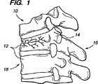
図1に示すように、椎骨の圧迫骨折は広く一般的な脊椎損傷を呈し、長期障害を招くことがある。これらの骨折には、脊椎10の1つ以上の椎体12の圧壊が含まれる。脊椎の圧迫骨折は、通常、胸椎の下方椎骨または腰椎の上方椎骨に生じる。圧迫骨折は、一般に、損傷を受けた椎体12の前方部分18(後側16の反対側)の骨折を含む。脊椎の圧迫骨折により、脊椎の損傷領域内の椎体の正常な整合または曲率の変形、例えば脊椎前弯が生じる。脊椎の圧迫骨折および/または関連する脊椎変形は、例えば、脊椎の転移性病変または外傷から生じることがあり、或いは骨粗しょう症に関係することもある。最近まで、医者は、いかにしてこのような圧迫骨折および関連変形を治療できるかに制限を受けてきた。利用できるオプションは、ペイン投薬、ベッド休息、ブレーシング(bracing)または侵襲性脊椎手術に過ぎない。
As shown in FIG. 1, vertebral compression fractures can cause widespread general spinal injury and can cause long-term disability. These fractures include the collapse of one or more
より最近になって、脊椎圧迫骨折の最小侵襲性外科手術が開発されている。これらの手術は、一般に、通常はペディクル(pedicles)を通して、損傷を受けた椎体の後方部分内に挿入されるカニューレまたは他のアクセスツールの使用を含む。これらの手術のうちの最もベーシックなものは椎骨形成術であり、この椎骨形成術は、文字通り、椎体の固定を意味し、骨の最初の整復を行うことなく実行できる。 More recently, minimally invasive surgery for spinal compression fractures has been developed. These surgeries generally involve the use of a cannula or other access tool that is inserted into the posterior portion of the damaged vertebral body, usually through pedicles. The most basic of these operations is a vertebral plasty, which literally means fixation of the vertebral body and can be performed without first reducing the bone.
簡単にいえば、カニューレまたは特殊な骨針が、背中の柔らかい組織を通してゆっくりと挿入される。少量のX線染料と一緒にイメージガイド形X線を用いることにより、針の位置を常時観察できる。少量のポリメチルメタクリレート(PMMA)または他の整形外科用セメントが、針を通して椎体内に押出される。PMMAは、多年に亘って種々の整形外科手術に使用されてきた医用物質である。一般に、セメントは抗生物質と混合されて感染の危険性を低減させ、バリウムまたはタンタルを含有する粉末は、X線で観察できる。 Briefly, a cannula or special bone needle is slowly inserted through the soft tissue of the back. By using an image-guided X-ray together with a small amount of X-ray dye, the position of the needle can be observed at all times. A small amount of polymethylmethacrylate (PMMA) or other orthopedic cement is extruded through the needle and into the vertebral body. PMMA is a medical substance that has been used in various orthopedic surgery for many years. In general, cement is mixed with antibiotics to reduce the risk of infection, and powders containing barium or tantalum can be observed by X-ray.
椎骨形成術は、骨折痛の低減または除去、更なる圧壊の防止および患者の運動能力の回復にとって有効である。しかしながら、この椎骨形成術は、骨折した骨を整復するものではなく、従って骨折による脊椎の変形の問題に対処するものではない。一般に、椎骨形成術は、損傷領域における隣接椎体間の脊椎後弯が10%以下である状況を除き行われない。また、最近の研究によれば、この手術は、低粘度セメントを用いた高圧セメント注入を必要とし、手術の30〜80%でセメントの漏洩が生じている。殆どの場合において、セメントの漏洩は無害である。しかしながら、稀には、ポリメチルメタクリレートまたは他のセメントが脊椎管または脊椎周囲の静脈系内に漏洩して肺動脈塞栓症を引起こし、患者を死に至らしめることがある。 Vertebroplasty is effective in reducing or eliminating fracture pain, preventing further collapse and restoring the patient's ability to exercise. However, this vertebroplasty does not reduce the fractured bone and therefore does not address the problem of spinal deformation due to fracture. In general, vertebroplasty is not performed except in situations where the vertebral kyphosis between adjacent vertebral bodies in the damaged area is 10% or less. Also, according to recent studies, this surgery requires high pressure cement injection with low viscosity cement, and cement leakage occurs in 30-80% of the surgery. In most cases, cement leakage is harmless. In rare cases, however, polymethylmethacrylate or other cement can leak into the vertebral canal or the venous system surrounding the spine, causing pulmonary embolism and causing the patient to die.
椎骨の圧迫骨折のより進歩した治療法として、一般に2つのフェーズすなわち(1)椎体の元の高さの整復または修復、従って脊椎前弯の矯正、および(2)強化、すなわち骨折した骨または圧壊した骨を支持しまたは強化する材料の添加がある。 More advanced treatments for vertebral compression fractures generally include two phases: (1) reduction or restoration of the original height of the vertebral body, and thus correction of the lordosis, and (2) enhancement, ie fractured bone or There is the addition of materials that support or strengthen the collapsed bone.
このような1つの治療法であるバルーン脊椎後弯形成術(Kyphon Inc.)が、下記特許文献1〜3に開示されている。尚、これらの特許文献1〜3はその全体を本願に援用する。拡大可能なバルーンチップを備えたカテーテルが、カニューレ、シースまたは他の導入器を通して、骨折した皮質骨により包囲された比較的柔らかい海綿骨からなる骨折した椎体の中央部内に挿入される。次に、椎体内で拡大するバルーンを膨張させて椎体をその元の高さに修復することにより、脊椎後弯形成術によって脊椎前弯の再形成すなわち正常曲率を達成する。バルーンを取出して椎体内に空隙を残し、次に、椎骨形成術に関連して上述したように、PMMAまたは他の充填材がカニューレを通して空隙内に注入される。カニューレが取出されかつセメントが硬化して、骨が強化され、充填されまたは固定される。
One such treatment, balloon kyphoplasty (Kyphon Inc.), is disclosed in
この手術の欠点は、コストが嵩むこと、バルーンカテーテルを取出した後に椎体の終板が失われることがあること、および手術中に椎骨の終板に孔があくことがあることである。椎骨形成術と同様に、椎骨後弯形成術に関して可能性は小さいとはいえ多分最も恐ろしい問題は、骨セメントの漏洩に関することである。例えば、椎骨管内への骨セメントの漏洩により、神経学的欠損が生じることがある。このようなセメント漏洩は、椎体の低耐性静脈により、または予知できなかった骨のクラックにより生じる。他の問題として、隣接レベルの付加椎骨骨折、感染およびセメント塞栓形成がある。セメント塞栓形成は、セメント漏洩と同様なメカニズムにより生じる。セメントは低耐性静脈系内に押出され、肺または脳に移動して肺動脈塞栓または発作を引起こす。 The disadvantages of this surgery are that it is costly, that the vertebral endplate may be lost after removal of the balloon catheter, and that the vertebral endplate may be perforated during the procedure. Like vertebroplasty, perhaps the most frightening problem with vertebral kyphoplasty is probably related to bone cement leakage. For example, leakage of bone cement into the vertebral canal can cause neurological deficits. Such cement leakage is caused by low tolerance veins in the vertebral body or by unforeseen bone cracks. Other problems include adjacent levels of additional vertebral fracture, infection and cement embolization. Cement embolization occurs by a mechanism similar to cement leakage. Cement is extruded into the low-resistance venous system and moves to the lungs or brain, causing pulmonary artery embolization or seizures.
椎骨圧迫骨折を治療する他のアプローチは、オプチメッシュシステム(Optimesh system)(Spineology Inc. Stillwater,ミネソタ州)である。オプチメッシュシステムは、椎体内に拡大可能なメッシュグラフトバルーンまたは収容器具を用いて、セメントまたは同種移植骨または自家移植骨の最小侵襲性デリバリを行う。バルーングラフトは、その膨張後に椎体内に留まり、このため、バルーン引出し時の脊椎後弯形成術中に生じる、整復の術中ロスを防止する。しかしながら、このシステムの1つの欠点は、メッシュインプラントが椎体内に首尾良く一体化しないことである。このため、インプラントと椎体との間に相対移動が生じ、従って整復の術後ロスが生じる。この手術に関する更なる詳細が、例えば下記特許文献4に開示されている。尚、この特許文献4は、その全体を本願に援用する。 Another approach to treating vertebral compression fractures is the Optimesh system (Spineology Inc. Stillwater, Minnesota). The Optimesh system performs minimally invasive delivery of cement or allograft bone or autograft bone using a mesh graft balloon or containment device that can be expanded into the vertebral body. The balloon graft remains in the vertebral body after its expansion, thus preventing intraoperative loss of reduction that occurs during kyphoplasty during balloon withdrawal. However, one drawback of this system is that the mesh implant does not integrate successfully into the vertebral body. This causes a relative movement between the implant and the vertebral body, thus causing a post-operative loss of reduction. Further details regarding this operation are disclosed, for example, in Patent Document 4 below. In addition, this patent document 4 uses the whole for this application.
椎骨圧迫骨折の治療に使用される更に別の手術は、スカイボーンエキスパンダ(SKy Bone Expander)として知られている膨張可能なポリマー強化マスである。この器具は、制御された態様で、予め設計されたサイズおよび形状(立方体または台形)に拡大される。キーフォンバルーン(Kyphon balloon)と同様に、ひとたび最適椎骨高さおよび空隙が達成されたならば、スカイボーンエキスパンダが取出され、PMMAセメントまたは他の充填材が空隙内に注入される。従って、この手術は、脊椎後弯形成術に関連して上述したのと同じ多くの欠点および欠陥を有している。 Yet another procedure used to treat vertebral compression fractures is an expandable polymer reinforced mass known as the SKy Bone Expander. The instrument is expanded in a controlled manner to a pre-designed size and shape (cube or trapezoid). Similar to the Kyphon balloon, once the optimal vertebra height and void have been achieved, the Skybone expander is removed and PMMA cement or other filler is injected into the void. This surgery therefore has many of the same drawbacks and deficiencies as described above in connection with kyphosis.
骨折した骨または損傷を受けた骨の或る場合には、損傷領域を補修しまたは治療するのに骨グラフトが使用される。米国だけで、年間約50万件の骨グラフト手術が行われ、これらの手術は、骨ロス、怪我または脊椎固定術(脊椎または関節のための固定術)による固定を必要とする他の状態を含む骨折等の問題への種々の医療的介入、および外傷、感染または病気により引起こされる他の骨欠損に関するものである。骨グラフティングには体内での骨片の外科的移植術があり、一般に人体資源から得たグラフト材料を用いて行われる。これは、主として、異種移植および他の種からの移植が制限されていることによる。 In some cases of fractured or damaged bone, bone grafts are used to repair or treat the damaged area. In the United States alone, approximately 500,000 bone graft operations are performed annually, and these operations can cause bone loss, injury, or other conditions that require fixation by spinal fusion (fixation for the spine or joint). It relates to various medical interventions for problems including fractures and other bone defects caused by trauma, infection or disease. Bone grafting involves the surgical implantation of bone fragments in the body and is generally performed using a graft material obtained from human resources. This is mainly due to limited xenotransplantation and transplants from other species.
整形外科用自家移植骨または自原性(autogeneous)グラフトとして、移植を受ける人と同じ個体から得た資源骨(source bone)がある。かくして、この形式の移植は、骨材料を体内の一部位から同じ体内の他の部位に移動させ、免疫学的問題を最小にできる長所を有している。自家移植骨を使用することは、必ずしも可能ではなく或いは好ましいものでもない。患者の体から骨材料を得ることは、一般に、移植手術とは別の手術を必要とする。また、材料の取出し(しばしば、骨盤領域または肋骨からの健康材料の使用を含む)は、特に、材料を取出した箇所で、患者はリハビリテーション中に更に不快感を増す傾向を有する。合成材料から形成されたグラフトも開発されているが、骨の特性に似せることの困難性のため、これらのインプラントの効能が制限されている。 Orthopedic autograft bones or autogeneous grafts are source bones obtained from the same individual as the recipient. Thus, this type of transplant has the advantage that bone material can be transferred from one part of the body to another part of the same body, minimizing immunological problems. The use of autograft bone is not always possible or preferred. Obtaining bone material from a patient's body generally requires an operation that is separate from the transplant operation. Also, material removal (often involving the use of health material from the pelvic region or ribs) tends to increase discomfort during rehabilitation, especially at the site where the material is removed. Grafts made from synthetic materials have also been developed, but the effectiveness of these implants is limited due to the difficulty of mimicking bone characteristics.
自家移植骨および合成グラフトにより提出される挑戦の結果として、多くの整形外科用手術は、他の人体資源(通常は死体)からの骨グラフトである同種移植骨の使用を含むものである。例えば骨グラフトは、宿主骨(host bone)内に配置されて、宿主骨から成長した新しい骨組織を支持する副構造体として機能する。グラフトは、骨折領域または欠損領域での挿入に適した形状になるように造形され、かつしばしば、例えばねじ、ピン、セメント、ケージ、膜等により当該領域に固定する必要がある。同種移植骨の資源材料が入手できることおよび医療社会においてこの材料が広く受入れられていることにより、同種移植骨組織の使用は、筋骨格手術の分野で広まる傾向を有している。 As a result of the challenges presented by autograft bones and synthetic grafts, many orthopedic surgeries involve the use of allograft bones that are bone grafts from other human resources (usually cadaver). For example, a bone graft is placed within a host bone and functions as a substructure that supports new bone tissue grown from the host bone. The graft is shaped to be suitable for insertion in a fracture or defect area and often needs to be secured to the area, for example by screws, pins, cement, cages, membranes, etc. Due to the availability of allograft bone resource material and the widespread acceptance of this material in the medical community, the use of allograft bone tissue tends to become widespread in the field of musculoskeletal surgery.
特に、例えば大腿骨(下肢)、脛骨および腓骨(脚)、上腕骨(上腕)、橈骨および尺骨(下腕)等の身体の種々の骨は、かなり異なった幾何学的形状を有している。また、これらの骨の長さは異なっており、例えば成人では、長さは47cm(大腿骨)から26cm(橈骨)まで変化している。更に、各種の骨の断面形状はかなり異なっており、所与の骨の形状は、長さよりも大きく異なっている。大腿骨はほぼ円形の外形を有しているが、脛骨はほぼ三角形の外形を有している。また、壁厚も各骨の種々の横断面で異なっている。かくして、インプラントコンポーネントを作るための任意の所与の骨の使用は、骨の直径および幾何学的形状に関連して定まる。しかしながら、骨を機械加工することにより、標準化された寸法またはカスタム寸法をもつインプラントコンポーネントを製造できる。 In particular, the various bones of the body, such as the femur (lower limbs), tibia and ribs (legs), humerus (upper arm), ribs and ulna (lower arm), have quite different geometric shapes. . The lengths of these bones are different. For example, in adults, the length varies from 47 cm (femur) to 26 cm (rib). Furthermore, the cross-sectional shapes of the various bones are quite different, and the shape of a given bone varies greatly over length. The femur has a generally circular profile, while the tibia has a generally triangular profile. The wall thickness is also different at various cross sections of each bone. Thus, the use of any given bone to make an implant component will depend on the bone diameter and geometry. However, machining bone can produce implant components with standardized or custom dimensions.
骨は、コラーゲンに富んだミネラル組織を有し、約40%の有機物質(主としてコラーゲン)と、残部の無機物質(主として、3Ca3(PO4)2Ca(OH)2)に似たほぼヒドロキシアパタイト組成)とからなる。構造的に、コラーゲンは、フィブリルの長さに沿って分布するヒドロキシアパタイト結晶をもつフィブリル生成物であり、個々のフィブリルは互いに平行に配置され、線維を形成している。骨の種類に基いて、フィブリルは、織り交ぜられるか、互いに垂直に配置された薄板として形成されている。 Bone has a mineral tissue rich in collagen, approximately hydroxy, similar to about 40% organic material (mainly collagen) and the rest of inorganic material (mainly 3Ca 3 (PO 4 ) 2 Ca (OH) 2 ). Apatite composition). Structurally, collagen is a fibril product with hydroxyapatite crystals distributed along the length of the fibrils, with the individual fibrils arranged parallel to each other to form fibrils. Depending on the type of bone, the fibrils are interwoven or formed as thin plates arranged perpendicular to each other.
骨組織は複雑なデザインを有し、骨の種類(すなわち、脚、腕または椎骨)および全体的構造に基いて、骨組織の特性が大きく異なっている。例えば長手方向に試験した場合、脚および腕の骨は約17〜19GPaの弾性係数を有しているのに対し、椎骨組織は1GPaより小さい弾性係数を有する。脚および腕の骨の引張り強度は約120〜150MPaの間にあるが、椎骨の引張り強度は4MPaより小さい。特に骨の圧縮強度は異なっており、大腿骨および上腕骨は、それぞれ、167MPaおよび132MPaの最大圧縮強度を有している。この場合も、椎骨は非常に小さい圧縮強度を有し、通常、10MPa以下である。 Bone tissue has a complex design and the characteristics of bone tissue vary greatly based on the type of bone (ie leg, arm or vertebra) and the overall structure. For example, when tested longitudinally, leg and arm bones have an elastic modulus of about 17-19 GPa, whereas vertebral tissue has an elastic modulus of less than 1 GPa. The tensile strength of the leg and arm bones is between about 120-150 MPa, while the tensile strength of the vertebrae is less than 4 MPa. In particular, the compressive strength of the bones is different, and the femur and humerus have maximum compressive strengths of 167 MPa and 132 MPa, respectively. Again, the vertebrae have a very low compressive strength, usually below 10 MPa.
所与の骨の全体的構造に関し、機械的特性は骨の全体に亘って変化している。例えば、大腿骨のような長骨(脚の骨)は、コンパクトな骨およびスポンジ状の骨の両方を有している。皮質骨、すなわち細いキャビティを包囲するコンパクトで稠密な骨は、一般に中実であり、従って大骨の荷重の大部分を支持する。海綿骨、すなわちスポンジ状の骨は一般に多孔質で延性があり、皮質骨と比較して、密度が約1/3〜1/4、剛さが約1/10〜1/20であるが、延性は約5倍である。海綿骨は約10〜20MPaの引張り強度および約0.7g/m3の密度を有するが、皮質骨は約100〜200MPaの引張り強度および約2g/m3の密度を有する。また、海綿骨の破壊歪みは約5〜7%であるのに対し、皮質骨は破壊前に1〜3%の歪みに耐え得るに過ぎない。これらの機械的特性は、骨材料に適用される何らかの化学的処理、および取出し後であるがインプラント前(すなわち、骨は乾燥している)の貯蔵方法等の多くのファクタの結果として劣化する。 For a given bone overall structure, the mechanical properties vary throughout the bone. For example, long bones (leg bones), such as the femur, have both compact and sponge-like bones. Cortical bone, a compact and dense bone that surrounds a thin cavity, is generally solid and therefore supports the majority of the load of the large bone. Spongy bone, or sponge-like bone, is generally porous and ductile, and has a density of about 1/3 to 1/4 and a stiffness of about 1/10 to 1/20 compared to cortical bone. The ductility is about 5 times. Cancellous bone has a tensile strength of about 10-20 MPa and a density of about 0.7 g / m 3 , while cortical bone has a tensile strength of about 100-200 MPa and a density of about 2 g / m 3 . Also, spongy bone fracture strain is about 5-7%, whereas cortical bone can only withstand 1-3% strain before fracture. These mechanical properties degrade as a result of many factors, such as any chemical treatment applied to the bone material and storage methods after removal but prior to implantation (ie, the bone is dry).
特に、海綿骨のインプラントは、皮質骨に比べて海綿骨の方が骨伝導性(osteoconduction)が優れているので、周囲の宿主骨により容易に一体化される。また、体の異なる領域から得た海綿骨は、一定範囲の空隙率を有することが知られている。例えば、腸骨稜の海綿骨は、大腿骨頭の海綿骨とは異なる空隙率を有する。かくして、海綿骨を用いたインプラントの設計は、所望の空隙率をもつ、特別に組込まれる材料に適合される。 In particular, cancellous bone implants are more easily integrated with the surrounding host bone because cancellous bone is more osteoconduction than cortical bone. Further, it is known that cancellous bone obtained from different regions of the body has a certain range of porosity. For example, the cancellous bone of the iliac crest has a different porosity than the cancellous bone of the femoral head. Thus, implant designs using cancellous bone are adapted to specially incorporated materials with the desired porosity.
当該技術分野では、骨折または他の損傷を受けた椎骨および他の骨を強化する安全かつ有効な器具および方法、好ましくは最小侵襲性移植方法を用いて移植される器具を提供することが要望されている。 There is a need in the art to provide safe and effective instruments and methods for strengthening fractured or other damaged vertebrae and other bones, preferably instruments that are implanted using minimally invasive implantation methods. ing.
本発明の一実施形態によるフレキシブルチェーンは、一連のすなわち複数の好ましくは中実で実質的に非フレキシブルなボディ部分(ボディまたはビーズとも呼ぶ)と、一連のフレキシブルリンク部分(リンクまたはストラットとも呼ぶ)とを有している。好ましくは中実で実質的に非フレキシブルなボディ部分は、あらゆる方向に加えられる荷重に耐えるのが好ましく、インプラントのフレキシブルリンク部分は、実質的に非フレキシブルなボディ部分の間に配置されるのが好ましく、選択された方向または所望の方向においてのみフレキシブルであるが、あらゆる方向にフレキシブルであるのが好ましい。ボディは、実質的に中実、半中実または中空であり、ボディが移植される位置で受ける荷重を支持する充分な強度を有するのが好ましい。リンク部分は、中実、半中実または中空であり、細長部材すなわちチェーンが曲げられるときに隣接ボディが互いに接触できるのに充分なフレキシビリティを有するのが好ましい。両部分すなわちフレキシブルリンク部分および非フレキシブルボディ部分は同じであるのが好ましく、かつ1つの単一フレキシブルモノリシックチェーン(flexible monolithic chain:FMC)を形成する。 A flexible chain according to an embodiment of the present invention comprises a series of, preferably a plurality of preferably solid, substantially non-flexible body parts (also called bodies or beads) and a series of flexible link parts (also called links or struts). And have. Preferably, the solid and substantially non-flexible body part is able to withstand loads applied in all directions, and the flexible link part of the implant is disposed between the substantially non-flexible body parts. Preferably, it is flexible only in the selected or desired direction, but is preferably flexible in all directions. The body is preferably substantially solid, semi-solid or hollow and preferably has sufficient strength to support the load experienced at the location where the body is implanted. The link portions are preferably solid, semi-solid or hollow and have sufficient flexibility to allow adjacent bodies to contact each other when the elongated member or chain is bent. Both parts, ie the flexible link part and the non-flexible body part, are preferably the same and form a single flexible monolithic chain (FMC).
本発明の一態様では、体組織例えば骨の強化器具は、フレキシブルな細長部材すなわちチェーンを有し、該細長部材はその高さまたは幅より実質的に大きい長手方向長さを有している。フレキシブルな細長部材は、複数の実質的に非フレキシブルなボディと、該ボディを相互連結する複数の実質的にフレキシブルなリンクとを有している。ボディおよびリンクは、端と端とが連結されて細長部材を形成し、細長部材は生体適合性材料で形成されている。 In one aspect of the present invention, a body tissue, eg, bone augmentation device, includes a flexible elongate member or chain, the elongate member having a longitudinal length substantially greater than its height or width. The flexible elongate member has a plurality of substantially inflexible bodies and a plurality of substantially flexible links interconnecting the bodies. The body and the link are connected to each other to form an elongated member, and the elongated member is made of a biocompatible material.
ボディはリンクとは異なるサイズおよび形状にするか、同じ形状およびサイズにすることができる。また、各ボディおよびリンクは、他のボディまたはリンクとは異なるサイズおよび形状にすることができる。一実施形態では、ビーズは、一体にフィットして隙間間隔が最小になるような形状を有している。例えば、ビーズは、これらのビーズ間に殆ど間隔が生じないように一体に重なり合うことができる立方体または他の多面体の形状にすることができる。 The body can be a different size and shape than the link, or the same shape and size. Also, each body and link can be a different size and shape than other bodies or links. In one embodiment, the beads are shaped to fit together and minimize gap spacing. For example, the beads can be in the form of a cube or other polyhedron that can overlap together so that there is little spacing between the beads.
細長部材は、例えば同種移植骨のような骨で形成できる一体モノリシックチェーンとして形成される。フレキシブルリンクは、ボディよりも高い度合いまで脱ミネラル化された骨で形成できる。任意であるが、細長部材の少なくとも一部にはコーティングを適用でき、コーティングは、例えば、治療剤、骨セメント、抗生物質、骨成長促進物質、骨形態発生プロテイン(bone morphogenic protein:BMP)またはこれらの任意の組合せからなる。治療剤または薬剤(例えば抗体)または生物学的物質(例えば1つ以上のBMP),がコーティングされるか、ペプチドを介して付着されるか、吸収されるか、他の或る方法で細長部材、すなわちボディ、リンクまたはこれらの両方の上または中に灌流される。或る実施形態では、コーティングは、骨内への挿入時に活性化される骨セメントで形成できる。他の実施形態では、ボディの少なくとも一部が、骨の内成長を促進するように構成された外面を有している。 The elongate member is formed as an integral monolithic chain that can be formed of bone, such as, for example, allograft bone. The flexible link can be formed with bone demineralized to a higher degree than the body. Optionally, a coating can be applied to at least a portion of the elongate member, such as a therapeutic agent, bone cement, antibiotic, bone growth promoter, bone morphogenic protein (BMP) or these It consists of arbitrary combinations. A therapeutic agent or drug (eg, an antibody) or biological material (eg, one or more BMPs) is coated, attached via a peptide, absorbed, or in some other way. I.e. perfused onto or into the body, link or both. In some embodiments, the coating can be formed of bone cement that is activated upon insertion into bone. In other embodiments, at least a portion of the body has an outer surface configured to promote bone ingrowth.
他の態様では、フレキシブルチェーンインプラントは、例えば小さく細い開口を通してキャビティ、空隙または中空スペース内に押し込まれるか、挿入される。このようなキャビティは、例えば、長骨、椎骨間円板スペースまたは椎体の空隙で形成できる。このような空隙は、感染、病気、外傷、骨折、変性円板の病気による突起、腫瘍または骨切り術により生じることがある。他の実施形態では、空隙は、移植前に、海綿骨または皮質骨または他の組織を詰め込みまたは取出すツールを用いて形成できる。その後、チェーンは、形成された空隙を充填すべく移植される。挿入力または詰め込み力に基いておよび挿入されたチェーン器具の長さに基づいて、器具は、組織構造好ましくは骨構造を復元サイズおよび/または高さに充填しおよび/または支持する。他の実施形態では、空隙またはキャビティが存在しないこともある。空隙またはキャビティが存在する場合には、チェーンインプラントすなわち細長部材が挿入されおよび/または移植され、骨内に物質および骨細胞を詰め込みかつ荷重をより良く支持できる態様で骨を更に充填し、好ましくは、骨をその元のサイズおよび高さおよび/または治療されたサイズおよび高さに復元させるように充填する。 In other embodiments, the flexible chain implant is pushed or inserted into a cavity, void or hollow space, for example through a small narrow opening. Such cavities can be formed, for example, by long bones, intervertebral disc spaces or vertebral body voids. Such voids can be caused by infections, illness, trauma, fractures, processes due to degenerative disc disease, tumors or osteotomy. In other embodiments, the voids can be formed using a tool that stuffs or removes cancellous or cortical bone or other tissue prior to implantation. The chain is then implanted to fill the formed void. Based on the insertion force or stuffing force and based on the length of the inserted chain device, the device fills and / or supports the tissue structure, preferably the bone structure, to a restored size and / or height. In other embodiments, there may be no voids or cavities. If voids or cavities are present, a chain implant or elongate member is inserted and / or implanted to further fill the bone in a manner that allows it to pack material and bone cells into the bone and better support the load, preferably The bone is filled to restore its original size and height and / or the treated size and height.
他の態様では、例えば長骨、感染、粉砕複雑骨折、腫瘍切除術および骨切り術の痕跡を治療すべく、1つ以上のフレキシブルモノリシックチェーンが、病変骨、損傷を受けた骨または異常な骨内に移植される。FMC器具はまた、例えば変性円板病変、虚脱椎骨間円板、椎体腫瘍または椎体骨折および椎体切除術を含む脊椎用途における病気または異常な病理学状態を治療するのにも使用できる。細長部材すなわちチェーンは、骨、脊椎円板を強化するための防止手段として、または融合を促進させる椎体間インプラントとしても使用できる。細長部材は、椎骨内または2つの椎骨間で使用できる。細長部材すなわちチェーンはまた、例えば、2つの椎骨間の円板スペース内に挿入されるインプラントとして、円板環状体内に挿入されかつ保持されるインプラントとして、例えば椎体間融合手術に使用でき、或いは2つの椎骨間の円板スペース内に挿入される付加インプラントと組合せて使用できる。 In other embodiments, one or more flexible monolithic chains may be used to treat diseased bone, damaged bone, or abnormal bone to treat, for example, traces of long bones, infections, comminuted fractures, tumor resections, and osteotomy. Transplanted in. FMC devices can also be used to treat diseases or abnormal pathological conditions in spinal applications including, for example, degenerative disc lesions, collapsed intervertebral discs, vertebral body tumors or vertebral fractures and vertebral body resection. The elongate member or chain can be used as a preventive means to strengthen the bone, spinal disc, or as an interbody implant that promotes fusion. The elongate member can be used within a vertebra or between two vertebrae. The elongate member or chain can also be used, for example, as an implant inserted into a disc space between two vertebrae, as an implant inserted and retained within a disc annulus, eg, for interbody fusion surgery, or It can be used in combination with additional implants that are inserted into the disc space between the two vertebrae.
他の実施形態では、本発明による組立体およびコンポーネンツの種々の組合せからなるキットが提供される。キットには、例えば、細長部材、例えばFMC器具、カニューレまたは他の導入器、または細長部材を移植する器具を入れるパッケージまたは容器を含めることができる。他の実施形態では、キットに、キャビティを形成する器具(例えばバルーンカテーテル)、FMC器具、およびセメントまたは他の充填材および/またはFMC器具および/またはこのような充填材を椎体内に注入するシリンジまたは他の器具を含めることができる。 In other embodiments, kits comprising various combinations of assemblies and components according to the present invention are provided. The kit can include, for example, a package or container containing an elongate member, such as an FMC instrument, cannula or other introducer, or an instrument for implanting the elongate member. In other embodiments, the kit is infused with a device forming a cavity (eg, a balloon catheter), FMC device, and cement or other filler and / or FMC device and / or such filler into the vertebral body. A syringe or other device can be included.
本発明は添付図面を参照して述べる以下の説明からより良く理解されよう。尚、全図面を通して、同じ要素には同じ参照番号が使用されている。添付図面は、単独で使用される特徴または他の特徴と組合せて使用される或る特徴を示すための単なる例示であり、本発明は図示の実施形態に限定されるものではない。 The invention will be better understood from the following description with reference to the accompanying drawings. Throughout the drawings, the same reference numerals are used for the same elements. The accompanying drawings are merely illustrative to illustrate certain features used alone or in combination with other features, and the invention is not limited to the illustrated embodiments.
図2を参照すると、チェーン(細長部材と呼ぶこともある)200は、1つ以上のボディ(ビーズと呼ぶこともある)210を有している。チェーン200は、好ましくはモノリシックチェーンであり、例えば、単一の共通材料または一体構造を形成する材料形式から形成される。ボディ210は好ましくは実質的に非フレキシブルであり、中実、半中実、多孔質、非多孔質、中空またはこれらの任意の組合せで構成できる。また、チェーン200は、1つ以上のリンキング部分(ストラットまたはリンクと呼ぶこともある)220を有している。ストラット220は、各対の隣接ボディ210間に配置される。ストラット220は、例えばボディ210間でチェーン200を曲げることができるように、実質的にフレキシブルまたは半フレキシブルであるのが好ましい。
Referring to FIG. 2, a chain (sometimes referred to as an elongated member) 200 has one or more bodies (sometimes referred to as beads) 210. The
チェーン200のボディ210は、例えば皮質骨、海綿骨またはこれらの両者のような骨で形成するのが好ましいが、皮質骨の方が好ましい。他の実施形態では、チェーン200は、所望の特性をもつ任意の生体適合性材料、例えば生体適合性ポリマー、金属、セラミック、複合材料またはこれらの任意の組合せで形成できる。ボディ210は、身体により吸収または再吸収可能な材料で形成できる。幾つかの用途では、ボディ210は好ましくは骨誘導性を有し、或いは少なくとも一部が骨誘導性材料から作られる。ボディの外周形状は隣接リンクと同じにすることができる。これとは別にまたはこれに加えて、ボディの外周形状は、隣接リンクと同サイズにすることができる。ボディ210は、均一サイズまたは不均一のサイズ、形状および/または材料で形成でき、かつ例えば1つ以上のフレキシブルまたは半フレキシブルリンキング部分220(該部分はボディ210間に任意の所望長さのストラットを形成できる)により直列にリンクされる。必ずしもそうである必要はないが、リンキング部分220は、ボディ210と同じ材料で形成するのが好ましい。
The
チェーン200は所望数のリンクされたボディ210を有し、かつ第一端部202および第二端部204を有している。他の実施形態では、チェーン200は、無端のルーフ、リングまたは他の形状に形成でき、或いは例えば木の枝のように多数の延長部および/または多数の端部を設けることもできる。
The
1つ以上のリンキング部分220は、フレキシビリティ、強度等の所望の特性を有する任意の生体適合性材料で形成できる。好ましい実施形態では、リンキング部分220は、その少なくとも一部が、ボディ210と実質的に同じ材料で形成できる。或る実施形態では、ボディ210および/またはリンキング部分220を備えたチェーン200は再吸収可能な材料で形成できる。ボディ210は均一サイズまたは不均一サイズにでき、かつリンキング部分220により均一または不均一な増分で間隔を隔てることができる。
The one or more linking
図2Bは、図2Aのチェーンの2B−2B線に沿う拡大断面図である。この例では、チェーン200はモノリシックチェーンであり、ボディ210およびフレキシブル部分220は、例えば骨のような均一材料で形成されている。ボディ210は実質的に球形として示され、リンキング部分220は実質的に円筒状として示されているが、他の多くの形状を考えることができる。実際に、ボディ210および/またはリンキング部分220を含むチェーン200は、例えば円筒状、楕円体、球体、直方体等の任意の所望形状にすることができる。ボディ210および/またはリンキング部分220はまた、円形、六角形、正方形等の任意の特定断面形状にすることができる。ボディ210およびリンキング部分220は、同じ形状または異なる形状にすることができる。或る実施形態では、ボディ210の形状は、例えば図5および図10に関連して説明するように、チェーン200内で変えることができる。これとは別にまたはこれに加えて、リンク220の形状もチェーン内で変えることができる。一実施形態では、ボディは、これらが、隙間間隔を最小にすべく一体に嵌合されるか、所定範囲の隙間間隔を形成するような形成にすることができる。
2B is an enlarged cross-sectional view of the chain of FIG. 2A along line 2B-2B. In this example, the
チェーン200の全ての寸法的特徴は、任意の特定解剖学的構造またはデリバリ器具に適合させることができる。例えば、椎体を強化する用途では、例えば図2Bに示すように、ボディ210の直径230は、約1mmと約15mmの間、好ましくは約2mmと約8mmとの間、またはより好ましくは約4mmと約6mmとの間に定めることができる。好ましくは、非フレキシブルボディ210は、フレキシブルストラット220より大きい形状およびサイズを有する。例えばストラット220の高さ232は、約0.5mmと約8mmとの間、好ましくは約0.8mmと約4mmとの間で定めることができ、一部はボディ210のサイズに基いて定めることができる。ストラット220は任意の所望長さ238、例えば約0.5mmと約5.0mmとの間、好ましくは約1.5mmと3.5mmとの間、または5mmより大きい寸法に定めることができる。同様に、ボディ210同士の間の距離234は、例えばボディ210のサイズおよびストラット220の長さ238に基いて任意の所望距離にすることができる。或る実施形態では、例えば距離234は、約4mmと約15mmとの間、または約6mmと約10mmとの間に定めることができる。ボディ210とストラット220との間の結合部は任意の所望寸法にすることができ、例えば1.0mm未満、約1.0mmと約2.0mmとの間、または約2.0mmより大きくすることができる。
All dimensional features of the
或る実施形態では、チェーン200のボディ210およびストラット220の各々はチェーン200内の他のボディ210およびストラット220と同じ形状および/または寸法にすることができる。他の実施形態では、チェーン内のボディ210および/またはストラット220は、異なる形状または寸法にすることができる。更に別の実施形態では、非フレキシブルボディ210およびフレキシブル部分220は同じ形状およびサイズにして、例えば図4に示すような比較的均一な構造を形成することができる。
In some embodiments, each of the
チェーン200は、できる限り特定用途に実用できるように作ることができる。例えば、骨内に移植するチェーン200の長さは約100mmにすることができる。他の実施形態では、チェーン200は、他の長さ、例えば約1mm未満、約1mmと約100mmとの間、または100mmより大きくすることができる。或る実施形態では、2つ以上のチェーン200および/または他のインプラントとを互いに組合せて使用することができる。チェーン200の端と端とを連結して、より大きいチェーンを形成することができる。
The
本発明は、好ましくは同種移植骨材料からインプラントを作ることに関するが、本発明は、例えば異種移植骨、自家移植骨、金属、合金、セラミック、ポリマー、複合材料、およびカプセル封入された流体またはゲルを含む次のような他の材料(但しこれらに限定されない)を用いたインプラントにも適用できる。また、本明細書で説明するインプラントは、例えば、空隙率のレベルが異なる種々の骨または種々の組織および/または材料を組合せた骨セクションのように、空隙率のレベルが異なる材料で形成できる。 Although the present invention preferably relates to making an implant from allograft bone material, the present invention relates to, for example, xenograft bone, autograft bone, metal, alloys, ceramics, polymers, composite materials, and encapsulated fluids or gels. It can also be applied to implants using other materials including, but not limited to: Also, the implants described herein can be formed of materials with different levels of porosity, such as, for example, various bones with different levels of porosity or bone sections that combine various tissues and / or materials.
また、本明細書で説明するインプラントは、ミネラル含有量が異なる骨材料で形成することもできる。例えば、例えば自然状態、部分的脱ミネラル化状態または脱ミネラル化状態の海綿骨または皮質骨で形成できる。脱ミネラル化は、一般に、塩酸等の酸の使用、キレート化剤、電気分解または他の処理を含む種々の化学的処理技術により行われる。脱ミネラル化処理は、自然骨中に含有されるミネラルを除去するもので、コラーゲン線維に骨形態発生プロテイン(bone morphogenic protein:BMP)を含む骨成長ファクタを残しておく。骨セクションの機械的特性は、脱ミネラル化の度合いを変えることにより変えることができる。有利なことは、例えば皮質骨または海綿骨等の骨に脱ミネラル化剤を使用することにより、骨の特性を剛性構造から比較的しなやかな構造に変形できることである。任意であるが、脱ミネラル化骨のフレキシビリティすなわちしなやかさは、骨を水和することにより高められる。本願明細書で広く「フレキシビリティ」と呼ぶ展性、弾性、しなやかさまたはフレキシビリティの所望の度合いを達成するため、骨コンポーネンツの所望部分、例えばリンク部分220または他の任意の所望部分は、脱ミネラル化または部分的に脱ミネラル化することができる。フレキシビリティの度合いは、脱ミネラル化の程度を変えることにより変えることができる。
The implants described herein can also be formed from bone materials having different mineral contents. For example, it can be formed of cancellous bone or cortical bone, for example in the natural state, partially demineralized state or demineralized state. Demineralization is generally performed by various chemical processing techniques including the use of acids such as hydrochloric acid, chelating agents, electrolysis or other processing. In the demineralization treatment, minerals contained in natural bone are removed, and bone growth factors including bone morphogenic protein (BMP) are left in the collagen fibers. The mechanical properties of the bone section can be changed by changing the degree of demineralization. Advantageously, by using a demineralizing agent on bones such as cortical bone or cancellous bone, the properties of the bone can be transformed from a rigid structure to a relatively supple structure. Optionally, the flexibility or suppleness of demineralized bone is increased by hydrating the bone. In order to achieve the desired degree of malleability, elasticity, suppleness or flexibility, generally referred to herein as “flexibility”, the desired portion of the bone component, such as the
或る実施形態では、脱ミネラル化領域または部分的脱ミネラル化領域のフレキシビリティは、インプラントまたはその一部の含水量を変えることにより更に高めることができる。次のような最初の骨コンポーネンツ、すなわち(a)ドナーから採取したばかりの凍結されていない自然状態の骨、(b)水分はそのままに、一般に−40℃で凍結された状態の骨、(c)フリーズ−ドライされた骨のように水分が除去された骨、および(d)水中に浸漬されたときのように水和状態にある骨には水分を与えることができる。骨材料の加熱および冷却中に得られる伸縮特性、および或る骨材料について膨潤と同時に生じる水分の再吸収を用いることにより、骨または他の領域内でのインプラントの所望のフレキシビリティを達成する他のアプローチが可能になる。 In certain embodiments, the flexibility of the demineralized region or partially demineralized region can be further increased by changing the water content of the implant or a portion thereof. First bone components: (a) unfrozen natural bone just taken from a donor, (b) bone in a frozen state, generally at −40 ° C., with moisture intact, (c Moisture can be given to bones that have been dehydrated, such as freeze-dried bones, and (d) bones that are in a hydrated state when immersed in water. Others to achieve the desired flexibility of the implant in bone or other areas by using the stretch properties obtained during heating and cooling of the bone material and the reabsorption of moisture that occurs simultaneously with swelling for some bone material Approach becomes possible.
インプラントは、その全体を、皮質骨、海綿骨または皮質骨と海綿骨との組合せから形成できる。インプラントは、その全体を全て骨材料で形成できるが、1つ以上のコンポーネンツまたは材料を、合成材料または他の材料を含む非骨材料で形成することもできる。かくして、本明細書に開示するインプラントは、一般に、主として骨から形成されると説明されているが、インプラントは、その全体または一部を、ステンレス鋼、チタンその他の金属、合金、ヒドロキシアパタイト、再吸収可能材料、ポリマーまたはセラミック等の他の材料で形成でき、更には、骨チップ、骨粒子、骨線維、骨成長材料および骨セメントを組込むことができる。また、本明細書では中実構造を説明したが、任意であるが、一方の外面から他方の外面まで延びている孔すなわち貫通孔、または外面に形成されかつ内面を通って延びてはいない凹部(表面多孔性)、または内部に形成された孔を備えた構造にすることもできる。外面には、凹みおよび/またはディンプルのような表面組織を形成することもできる。凹みおよび/またはディンプルは、円形、ダイヤモンド形、矩形、不規則形状または他の形状にすることができる。 The implant can be formed entirely from cortical bone, cancellous bone or a combination of cortical and cancellous bone. An implant can be formed entirely of bone material, but one or more components or materials can also be formed of non-bone material, including synthetic or other materials. Thus, although the implants disclosed herein are generally described as being formed primarily from bone, the implant may be entirely or partially made of stainless steel, titanium or other metals, alloys, hydroxyapatite, It can be formed of other materials such as resorbable materials, polymers or ceramics, and can further incorporate bone chips, bone particles, bone fibers, bone growth materials and bone cement. Also, although a solid structure has been described in the present specification, it is optional, but a hole extending from one outer surface to the other outer surface, that is, a through hole, or a recess formed in the outer surface and not extending through the inner surface (Surface porosity), or a structure having pores formed in the inside may be employed. A surface texture such as a dent and / or dimple can also be formed on the outer surface. The recesses and / or dimples can be circular, diamond-shaped, rectangular, irregular or other shapes.
本明細書で説明するフレキシブルモノリシックチェーンは、長骨感染、粉砕複雑骨折、腫瘍切除術および骨切り術等の一般的な整形外科の病気および病的状態を治療するのに使用できる。また、器具は、例えば、変性円板病変、圧壊椎間板、椎体腫瘍または骨折、椎体切除または全体的不安定椎体のような脊椎の病気および病的状態に使用できる。他の実施形態では、フレキシブルモノリシックチェーンは、顎顔面用途または非融合核置換手術(non-fusion nucleus replacement procedure)に使用できる。 The flexible monolithic chains described herein can be used to treat common orthopedic diseases and pathological conditions such as long bone infections, comminuted fractures, tumor resections and osteotomy. The instrument can also be used for spinal diseases and pathological conditions such as, for example, degenerative disc lesions, collapsed intervertebral discs, vertebral body tumors or fractures, vertebral body resections or totally unstable vertebral bodies. In other embodiments, the flexible monolithic chain can be used for maxillofacial applications or non-fusion nucleus replacement procedures.
図3は、骨物質310からモノリシックチェーン器具探知システム200を製造する方法300の一例を示すものである。この例では、ベース材料として、同種移植骨大腿骨、好ましくは皮質同種移植骨が使用される。インプラントを形成するのに、他の骨例えば、橈骨、上腕骨、脛骨、大腿骨、腓骨、尺骨、肋骨、骨盤、椎骨または他の骨を使用できる。
FIG. 3 shows an example of a
図3Aに示すように、第一段階は、原材料好ましくは骨310から作った全体的所望形状を有する粗いモノリシックチェーン200′を機械加工することからなる。例えば、慣用のフライス加工技術および/または他の製造技術を使用できる。器具200は、図示のように円筒状リンキング部分220により分離された全体として楕円形または球形のボディ210を備えた任意の所望形状にすることができる。或いは、チェーン200は、例えば図4に示すように、実質的に均一な形状に形成できる。
As shown in FIG. 3A, the first stage consists of machining a coarse
図3の段階Aで全体的所望形状に機械加工した後、粗いモノリシック器具200′は、次に、段階Bに示すように原材料310から取出される。この例では、粗い器具200′の上面312は、上述のような所望の全体的形状を有するように製造された。しかしながら、反対側の面314には、段階Aで除去されなかった過剰の材料が含まれている。
図3の例示方法の段階Cでは、例えば慣用のフライス加工方法を用いて過剰の材料を除去すべく、反対側の面314が機械加工される。ボディ210およびリンキング部分220の所望の形状をもつモノリシックチェーン器具200を形成するため、所望に応じて上面312を更に機械加工または成形できる。
After machining to the overall desired shape in stage A of FIG. 3, the coarse
In step C of the exemplary method of FIG. 3, the
段階Dでは、成形されたチェーン200が骨から形成されたものである場合には、例えば脱ミネラル化溶液(例えば塩酸)322を収容している容器320内で、または他の方法を用いて脱ミネラル化される。脱ミネラル化は、例えば、器具200のより小さい体積部分220がよりフレキシブルまたは弾性を有するようになり、これに対し器具のより大きいボディ210は構造的にそのままで実質的に剛性を維持できるようにするため、特定時間だけ行われるように構成できる。所望度合いのフレキシビリティまたは弾性を得るため、時間の長さおよび/または脱ミネラル化溶液の濃度または組成を変えることができる。
In stage D, if the molded
或る実施形態では、脱ミネラル化のこの2次プロセスは、例えば処理されない部分または処理すべきでない部分をマスキングまたはシールディングすることにより、器具200の特定部分に適用できる。例えば、非フレキシブル部分210をマスキングすることにより、フレキシブル部分220は部分的または全体的に脱ミネラル化され、非フレキシブル部分的210は、マスキング前のこれらの元のミネラル化された状態を維持する。或いは、同種移植骨は、器具のいかなる部分をもマスキングすることなく、脱ミネラル化酸中に全体を浸漬させることができる。脱ミネラル化剤に曝される表面積を有するフレキシブル部分220の比較的小さい形状およびサイズにより、および例えば脱ミネラル化酸に曝される量に基いて、フレキシブル部分220は全体的に脱ミネラル化されるか、表面脱ミネラル化のみを受ける大きい部分210より少なくとも実質的に多く脱ミネラル化される。従って、小さい方の部分220はフレキシブルおよび弾性になり、一方、大きい方の部分210は比較的剛性で実質的に非フレキシブルを維持する。例えば、図2Bには、実質的に脱ミネラル化された領域240と、実質的に天然のすなわち元の組成およびミネラル化状態を有する領域242とが示されている。
In certain embodiments, this secondary process of demineralization can be applied to a particular portion of the
下記表1には、異なるストラット形状を有するを有する4つのモノリシックチェーンの脱ミネラル化時間の例が示されている。各チェーンは皮質同種移植骨で形成されかつ約5mmの直径をもつボディ部分210を有している。ストラット220の形状および寸法は、サンプル間で異なっている。4つの全てのサンプルで、ストラットは約3.5時間と4時間との間で完全に脱ミネラル化されたのに対し、ビーズは或る程度脱ミネラル化されたが、厚さ全体に亘って完全には脱ミネラル化されなかった。ストラットの寸法は図2Bの距離234に一致し、一方、ストラットの半径は図2Bの半径236に一致する。完全なフレキシビリティとは、チェーンにクラッキングまたは破壊が生じることなく2つの隣接ビーズが互いに接触するまでチェーンが曲ることができるときの状態であると考えられる。これは充分なフレキシビリティを評価する1つの方法であるが、フレキシビリティの他の評価方法を考えることもでき、本発明は、フレキシビリティのこのような評価方法に限定されるものではない。例えば、椎骨内に挿入して椎骨終板を強化しかつ支持するのに、完全なフレキシビリティをもたなくても充分でかつ望ましいこともある。
Table 1 below shows examples of demineralization times for four monolithic chains having different strut shapes. Each chain has a
表1:異なるストラット形状を有する直径5mmのチェーンの脱ミネラル化時間の例

下記表2は、塩酸浴への曝し時間と、表1のサンプル(例えばサンプル1)のストラット部分220のフレキシビリティの近似増分的変化との関係を例示するものである。
Table 2 below illustrates the relationship between the exposure time to the hydrochloric acid bath and the approximate incremental change in flexibility of the
表2:酸浴への曝し時間とストラットのフレキシビリティの増分的変化との関係
もちろん、酸浴の濃度、チェーン直径、温度、元の骨サンプルのミネラル化度合いおよび状態等を含む多くのファクタに基いて、他のサンプルは、種々の曝し時間内で異なるフレキシビリティを達成するであろう。 Of course, based on many factors, including acid bath concentration, chain diameter, temperature, mineralization degree and condition of the original bone sample, other samples may achieve different flexibility within different exposure times. I will.
モノリシックチェーンインプラントまたは他のチェーンインプラントを製造する他の種々の形態および方法を使用できる。方法の選択の少なくとも一部は、特定チェーン器具200に使用すべき材料(単一または複数)に基いて定められる。器具が生体適合性ポリマー材料で作られる場合には、器具は、フライス加工または旋削加工等の慣用製造方法により製造できるが、これらに限定されるものではない。或いは、チェーン器具200が生体適合性ポリマー材料から作られる場合には、器具全体を射出成形することもできる。
Various other forms and methods of manufacturing monolithic chain implants or other chain implants can be used. At least a portion of the method selection is determined based on the material (s) to be used for the
チェーン200が金属材料で作られる場合には、チェーンは、フライス加工または旋削加工等の慣用製造方法を用いて製造できるが、これらに限定されるものではない。しかしながら、フレキシブルコンポーネンツには、焼きなまし等の2次処理を施すことができる。2次加工は、例えば非フレキシブル部分をマスキングまたはシールディングすることにより、器具のフレキシブル部分のみに限定できる。
When the
或る実施形態では、チェーンインプラント200は、少材料セクション(例えば、比較的細くてフレキシブルな部分220)の領域での充分なフレキシビリティを考慮に入れると同時に、大きい剛性を有しかつ荷重支持特性を考慮に入れたより大きいセクション(例えばボディ210)を有する任意の種類の生体適合性材料で形成できる。少材料部分220は、割れまたは破壊されることなく好ましくはあらゆる方向にフレキシブルで、しなやかで或いは弾性特性を有している。或いは、小材料部分210は、器具200の挿入中または装入方法の他の段階に割れることを考慮に入れて、空隙の適正充填を考慮に入れることができる。材料は、チタンおよびスチールを含む金属にすることができるが、これらに限定されるものではない。ポリマー或いは同種移植骨組織材料を使用することもできる。骨に代えてまたは骨に加えて、器具200には、1つ以上の他の材料、例えば金属(チタン、スチールまたは他の金属)、合金またはポリマーを使用できる。或る実施形態では、器具200の材料は、骨伝導性、骨誘導性および/または骨形成性をもたせることができる。他の実施形態では、インプラント器具200は、非モノリシック材料で作ることができる。
In some embodiments, the
図4A〜図4Cに示すように、チェーン200は、任意の所望の幾何学的形状にすることができる。例えば、剛性部分210およびフレキシブル部分220は、立方体、円筒状、任意の多面体形状、ボール、バナナ形またはインゲン豆形またはこれらの任意の組合せ等の同じ形状または異なる形状にすることができる。部分210および/または部分220は、例えば矩形、円形、楕円形、五角形、六角形等の任意の所望断面形状にすることができる。フレキシブル部分220および非フレキシブル部分210は、図4A〜図4Cに示すように比較的均一な形状の構造を形成する同じ形状にすることができる。
As shown in FIGS. 4A-4C, the
図5に示すように、1つ以上のボディ210には、キャビティ510および中央孔512を設けることができる。このような孔512またはキャビティ510は空所でもよいし、例えばセメント、骨充填材、接着剤、移植片材料、治療剤または他の任意の所望物質で充填することもできる。充填材には放射線不透過性剤を混入しておき、手術中および手術後にチェーンまたはボディを視認できるようにすることができる。他の実施形態では、インプラント器具200は、骨の治癒をサポートおよび促進し、感染を低下させ、および/または治療部位に治療剤を配給する種々の物質でコーティングすることができる。例えば、器具200またはその一部は、抗生物質、BMP、骨成長促進剤、多孔質または非多孔質の骨内成長剤、治療剤等でコーティングすることができる。インプラントには放射線不透過性剤を組込んでおき、手術中および手術後にチェーンまたはボディを視認できるようにすることができる。また、チェーンインプラントの或る部分の上または部分の中には、治療剤、薬剤、BMP、組織成長促進剤、骨誘導剤を吸収させまたは灌流させることができる。更に、中実の非フレキシブル部分210には、種々の物質または薬剤が充填されるキャビティ、縦孔または横孔またはこれらの組合せを設けることができる。
As shown in FIG. 5, one or
図6Aおよび図6Bに示すように、損傷を受けた椎体12例えば次の椎骨圧迫骨折を強化する最小侵襲方法は、1つ以上のチェーン200を、終板614と終板616との間の椎体12の内部612内に移植することからなる。もちろん、圧迫または圧迫骨折前に、椎骨を強化すべく、予防措置として1つ以上のチェーン200を移植することができる。椎体12の外側皮質シェル内には、トロカール、ドリルまたは他の器具により孔を形成することができる。次に、例えば椎体12内に挿入されたカニューレ602または他の導入器を通してチェーン200を移植することができる。カニューレ(該カニューレを通してチェーン200が導入される)を挿入する適当な手術および材料は当該技術分野で既知であり、脊椎後弯形成術および他の手術について上述したのと同様である。例えば、カニューレ602は椎体12の後部16、例えばペディクル14を通して導入される(例えば、経ペディクルアプローチ)。チェーン200が挿入され、椎体内に海綿骨および骨粗しょう症の骨を詰め込む。
As shown in FIGS. 6A and 6B, a minimally invasive method of strengthening a damaged
カニューレの挿入前に、例えばドリルまたは他の器具を用いて、椎体内に通路が形成される。次に、チェーン200が通路を通して挿入され、椎体内に骨材料を詰め込むすなわち圧縮する。或いは、椎体内に通路が形成された後に、例えばキューレットまたはバルーンカテーテルを用いて椎体内の骨を圧縮しかつ詰め込んでキャビティを形成する。次に、この器具が取出される。或いは、カテーテルのバルーンカ部分を椎体内に留めておき、インプラントの容器を形成することもできる、また、椎体内のキャビティは、骨を詰め込むのではなく、骨材料を除去することによっても形成できる。例えば、リーマその他の器具を用いて、椎体内から骨材料を除去することができる。
Prior to insertion of the cannula, a passage is formed in the vertebral body using, for example, a drill or other instrument. Next, the
チェーン200のよりリンクされたボディ210が椎体12内に挿入されたときに、どれほどのキャビティが骨構造内に最初に形成されるか、或いはチェーン(単一または複数)が最初にキャビティを形成することなく挿入されたとしても、ボディは中央部分612を充填して構造的支持体を形成し、椎体を安定化する。圧壊された椎骨では、チェーンインプラント200が中央部分612を充填するので、インプラント、特にリンクされたボディ210が終板614、616の内部すなわち内面を押すことができ、このため、椎体12を圧壊された高さh1からその元の高さすなわち所望の治療高さh2まで修復させることができる。チェーンインプラントを挿入して椎骨の高さを修復させる代わりに、通路を通して器具を挿入し、椎骨および終板の高さを修復させることができる。例えば、バルーンカテーテルを挿入して椎骨の終板を修復するか、終板の内面に接触してこれらを押し拡げる細長器具を使用することもできる。また、チェーンのボディ210同士の間の1つ以上の部分220のフレキシビリティにより、チェーンを、スペース612内で例えば均一パターンまたは不均一または曲りくねった形状で曲げ、これにより、骨12内でのインプラント200の完全一体化を確保できる。また、フレキシブル部分により取付けられたボディ210の構成により、キャビティおよび/または椎骨を実質的に充填するように曲げることができ、このため、さもなくば弱化スポットマッチング弱化骨構造を形成することになる大きいポケットまたは空隙が形成されまたは留まることがなくなる。フレキシブルリンクはまた、チェーンが圧縮されてもつれ合うことを可能にし、これにより、チェーンはその挿入孔より大きくなって容易には飛び出なくなる。
How many cavities are initially formed in the bone structure when the more
他の実施形態では、チェーン200は、例えばカニューレ602のルーメン604または他のシースを通して椎体12等の骨内に挿入され、このようなシースは骨12内の移植後に取出される。このような実施形態では、チェーン200またはその一部が椎体12内に留まって、例えば椎骨を強化しかつ適正な脊椎前弯を維持し続けることができる。他の実施形態では、PMMAまたは他の骨セメントまたは充填材(例えば骨チップ)が、ボディ210と一緒に例えばシャフトおよび/またはカニューレ602を通して、連続的または同時的に椎体12内に挿入され、損傷を受けた領域の固定または補修効果を更に高める。或いは、チェーン200を挿入すべく最初に形成された孔内に、骨セメントのプラグ(例えば図8Aのプラグ812)のみを挿入できる。プラグは、挿入孔をカバーして、インプラント(チェーン)が取出されることおよび飛び出ることを防止する。他の実施形態では、チェーン200の幾つかのボディまたは全てのボディ210が骨の整復後に取出され、PMMAまたは他の骨セメントまたは充填材が、チェーン200により形成された空隙内に注入される。或いは、骨成長促進充填材が、椎体12内、およびリンクされたボディおよび充填材を椎骨内に保持すべく使用される骨セメントのプラグ内に挿入される。
In other embodiments, the
或る実施形態では、フレキシブルチェーン200が接着剤でコーティングされ、これにより、チェーン200は、フレキシブル状態で椎体12内に挿入されかつ挿入時または挿入後にもつれ合いおよび/または絡み合うようになる。挿入後に、ボディ210は接着剤により一体に取付けられ、これにより、フレキシブルチェーンは椎体内にロックされる塊となるか、チェーンが挿入開口を通して容易には取出されないようになる。
In certain embodiments, the
他の実施形態では、リンクされたボディ210が接着剤でコーティングされ、チェーンは、もつれ合いかつ絡み合って、またはもつれ合うことおよび絡み合うことなく、椎体内に挿入される。チェーン200の幾つかのまたは全てのリンキングボディ210の挿入中または挿入後に、チェーン200の一部がエネルギ源(例えば、紫外線、超音波、高周波、熱、電界、磁界)に曝され、例えば接着剤を活性化する。これにより、チェーン200の曝された部分が結合されて塊を形成または剛性になり、これにより、椎体12が更に強化されおよび/またはチェーン200が挿入開口を通って取出されまたは飛び出ることを防止する。
In other embodiments, the linked
図7は、椎体12の一部612内に移植された1つ以上のチェーン200を有する椎体12を示す平断面図である。1つ以上のチェーン200は、前述のように、1つ以上のリンキング部分により直列に結合された複数のボディ210を有する。1つ以上のカニューレ602(各カニューレはリンクされたボディ210を通す充分なサイズのルーメン604を有している)を使用して、チェーン200を椎体内に移植する。1つ以上のカニューレ602は、好ましくはペディクルを通して椎体12内に挿入される。或る実施形態では、1つ以上のカニューレ602は椎体12内に残され、例えばストラット(図示せず)により所定位置に保持されたペディクル14から延びている状態に留められる。
FIG. 7 is a cross-sectional plan view showing a
或る実施形態では、チェーン200は、図8Aに示すように椎体12内に完全に移植され、カニューレまたは他の導入器は取外される。チェーンは骨内に完全に留められる。チェーン200が挿通された通路810は、例えば骨セメントプラグ等のプラグ812が充填される。或いは図8Bに示すように、チェーン200の端部204は、骨の挿通孔、例えば椎骨12のペディクル14を通って延びている状態にしておく。図8Cに示す他の実施形態では、例えば骨ねじ800のような他のインプラントまたは器具がチェーンインプラント200と組合せて椎体12内に挿入され、椎体12を更に強化する。例えば、椎体12を整復するための永久的な力を椎体に伝達するアンカー要素として、伸長した端部204または付加インプラント800を使用できる。ねじ800は、チェーンの挿入に使用された開口内挿入され、チェーンが外れたり飛び出すことを防止するプラグとして更に機能する。ねじ800は、中空または中実のいずれでもよく、またステンレス鋼、合金、セラミック、ポリマー、複合材料または他の任意の所望材料で作ることができる。或る実施形態では、ねじ800は、例えばカニューレ602のルーメン604のようなルーメンからなる中空にして、椎体12内にチェーン200を挿入する通路を形成する導入器として使用できる。椎体12内には骨セメントまたは他の材料を注入して、インプラント200および/または800を更に固定しかつ椎体12を強化することができる。骨セメントまたは他の材料は、ねじのカニュレーションを通して挿入できる。
In some embodiments, the
図9A〜図9Dには、椎体内に移植されるフレキシブルモノリシックチェーン器具の他の例が示されている。図9Aでは、チェーン器具200が、例えば滅菌パッケージまたは容器から開封された後に、チェーン200を骨の所望キャビティ、空隙、スペースまたは内部に挿入しおよび/または詰めることを補助する導入器またはデリバリ器具910内に入れられる。この例では、デリバリ器具910が細長いカニューレ状シャフト912を有し、該シャフト912は、チェーン200が挿通されるルーメンを有している。器具910は、チェーン200の装填を容易にしおよび/または移植前にチェーン200の一部を保持するためのファンネル914または他の構造を有している。挿入器具910の挿入端916はチップ918を有し、該チップ918は、骨または他の構造内への端部916の挿入を容易にするのに望ましい鈍角、尖鋭、テーパ状または他の形状を有している。
9A-9D show another example of a flexible monolithic chain device that is implanted into the vertebral body. In FIG. 9A, an introducer or
図9Bは、挿入器具910のチップ918が椎体の内部612に入るように、挿入器具910の端部016が椎体12のペディクル14を通って挿入されるところを示している。椎体の外側皮質シェルには、トロカール、ドリルまたは他の器具により、導入器910を挿入する通路となるアクセス孔が形成される。所望領域例えば椎体12内にデリバリ器具910の端部916が挿入された後、好ましくはペディクルを通してチェーン200が挿入される。
FIG. 9B shows the end 016 of the
図9Cは、チェーン200の第一端部202が、導入器910を通して椎体12のスペース612内に挿入されているところを示している。チェーン200は、導入器910を通してチェーン200を押し込むべく、例えばチェーンの反対側の端部204から軸線方向の力を手で加えることにより、椎体12内に押し込まれる。他の実施形態では、例えば図11〜図13に関連して後述するように、チェーン200を移植させる軸線方向力を加えるのに、押し込み部材、スプロケット、ねじ機構または他の器具が使用される。或る実施形態では、1つの長いフレキシブルモノリシック器具200が、手術部位内に挿入されかつ移植される。或いは、種々の短いチェーン器具200および/または他の器具が、所望のキャビティ、空隙またはスペース内に詰め込まれまたは挿入される。多くの短いチェーン器具は、これらが挿入されるとき、端部と端部とが互いに連続的に取付けられる。この態様では、1つのチェーンが殆ど挿入されかつ一端が患者から出ているので、部分的に挿入されたチェーンに次のチェーンが取付けられる。図9Dには、1つ以上のチェーン200が椎体12の中央部612内に完全に挿入されているところが示されている。
FIG. 9C shows the
上記特許文献5には、FMCを導入するカニューレを挿入する他の適当な方法および材料が開示されている。尚、この特許文献5はその全体を本願に援用する。椎体内への挿入中に、チェーンまたは他のインプラント200が、圧壊された椎体内に海綿骨および/または骨粗しょう症の骨を詰め込む。或いは、椎体内で骨を圧縮しかつ詰め込むみキャビティを形成するのに、例えばキューレットまたはバルーンカテーテル等のツールが使用される。椎体内のキャビティはまた、骨を詰め込むのではなく骨材料を除去することによっても形成される。例えば、椎体内から骨材料を除去するのに、リーマまたは他の器具を使用できる。
The above-mentioned patent document 5 discloses another suitable method and material for inserting a cannula for introducing FMC. In addition, this patent document 5 uses the whole for this application. During insertion into the vertebral body, a chain or
他の実施形態では、インプラント200と同時に、例えば導入器910、または他のカニューレ、シース、シリンジまたは他の導入器を通して、PMMAまたは他の骨セメントまたは充填材(例えば骨チップまたは骨のリーマ加工から収集された材料)が椎体12内に挿入され、損傷領域の固定または補修を更に促進する。或いは、PMMA、骨セメントまたは充填材は、チェーン(またはその一部)が骨の内部に挿入された後に骨の内部に挿入できる。或いは、骨成長促進充填材が椎体内に挿入され、骨セメントのプラグを用いてインプラント200および充填材を椎体12内に保持する。この態様では、セメントのプラグが骨の内部に挿入されることはなく、インプラントを挿入すべく骨に形成された開口をカバーする。
In other embodiments, PMMA or other bone cement or filler (eg, from bone chip or bone reaming, eg, through the
図10A〜図10Cには、インプラントおよび挿入器具の最小侵襲性融合または非融合システムが示されている。前述のように、フレキシブルモノリシックチェーン器具1000が、図10Aに示すように、例えばカニューレ1030またはペディクル14を通して挿入された導入器を通して椎体12内に挿入される。任意であるが、湾曲チップまたは変形チップ1034を備えたガイドまたは他のツール1032が、カニューレ1030を通して挿入され、椎体12の終板を反らしおよび/またはチェーン1000のボディ1010を所望方向に案内すべく作用する。チェーン1000が椎体12内に押し込まれると、チェーン1000のフレキシブル部分1020が曲って、チェーン1000が、中央部612を充填すべく所望方向に曲ることができるようにする。フレキシブル部分は、インプラントが、好ましくは最小空隙率すなわち最小開スペースで骨の内部を実質的に充填すべく、インプラント自体の上に折畳まれることができるようにする。
10A-10C illustrate a minimally invasive fusion or non-fusion system of implants and insertion instruments. As described above, the flexible
図10Bに示すように、チェーン1000は、異なる形状のフレキシブル部分すなわちストラット1020および非フレキシブル部分1010を有している。例えば、フレキシブルジョイント1020は、非フレキシブル部分1010より細くなっている。非フレキシブル部分1010は、インゲン豆の形状、直方体または他の任意の形状にすることができる。幾つかの非フレキシブルボディは他の非フレキシブルボディとは異なるサイズおよび形状にすることができ、例えば、これらの非フレキシブルボディは、幅Y1を有する第一非フレキシブルボディ1010−1から、この幅Y1よりも大きい幅Y2をもつ最終の非フレキシブルボディ1010−5まで、サイズを増大させることができる。例えば図10Bの例示実施形態では、幅Y1は約5mmと約2mmとの間またはこれより小さく、幅Y2は約6mmと約8mmとの間またはこれより小さい。同様に、ボディ1010−1の長さX1は、ボディ1010−5の長さX2より実質的に短い。例えば、図10Bの例示実施形態では、長さX1は約2mmと約6mmとの間、長さX2は約6mmと約14mmとの間にすることができる。チェーン1000の全長は所望用途によって、例えば約10mmから約150mmの範囲、より好ましくは約40mmから約100mmの範囲で変えることができる。もちろん、本発明の範囲から逸脱することなく、ボディ1010および/またはフレキシブル部分1020の種々の他のサイズおよび相対的に異なる幅のサイズ、周囲、形状曲率または他の寸法を採用することができる。
As shown in FIG. 10B, the
或る実施形態では、1つ以上のボディ1010に1つ以上の開口またはキャビティ1012または1014を設けることができる。これらの開口またはキャビティ1012、1014は空所とすることもできるし、例えばセメント、骨充填材、接着剤、グラフト材料、治療剤または他の任意の所望材料で充填することができる。他の実施形態では、インプラント器具1000には、骨の治癒をサポートしかつ促進する種々の物質、感染を低下させる物質および/または治療部位に治療剤を配給する物質をコーティングすることができる。また、非フレキシブル部分またはフレキシブル部分は、例えば骨または他の組織の成長を容易にするため、多孔質表面1016とすることができる。
In some embodiments, one or
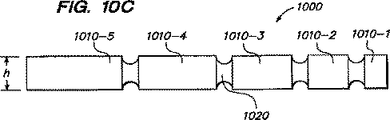
図10Cには、実質的に直方体または円筒状のボディ1010−1、1010−2、1010−3、1010−4および1010−5を有するチェーン1050の他の実施形態が示されている。これらのボディは、フレキシブルリンク部分1020で分離されており、互いに同寸法または異なる寸法にすることができる。図10Cにおいて、全てのボディ1010−1、1010−2、1010−3、1010−4および1010−5は同じ高さhを有するが、長さは異なっている。図10Cのストラット1020は、ボディ1010とは異なる小さい高さを有している。
FIG. 10C shows another embodiment of a chain 1050 having a substantially rectangular or cylindrical body 1010-1, 1010-2, 1010-3, 1010-4 and 1010-5. These bodies are separated by
図11は、チェーン200を骨または他の所望構造内に移植するための挿入器具1100を示す側断面図である。例えば挿入器具1100は、壁1122およびルーメン1223を備えた挿入チューブすなわちカニューレ1120を有している。ルーメン1223内には、この少なくとも一部を通って、回転ねじ機構1110が配置されている。ねじ機構1110は、アキシャルシャフト1112を包囲する螺旋状ねじ山1114を備えている。ねじ山1114は、好ましくはシャフトから延びており、例えばボディ210同士の間でチェーン200と係合する寸法およびスペースを有している。例えばハンドル1130を回転させることによりねじ1110を回転させると、ねじ山1114がボディ210と係合して、チェーン200をカニューレ1120のルーメン1223を通して、所望の骨または他の領域内へと軸線方向に押しやる。このような挿入器具はインプラントの挿入力を高めることができ、例えば、椎体の終板を移動させて終板の高さを復元し、インプラントの一領域の海綿骨を圧縮させ、またはインプラントを所望領域内に押しやることができる。
FIG. 11 is a side cross-sectional view illustrating an
図12および図13には、導入器を通してチェーン200を所望領域内に押しやる他の機構を示すものである。より詳しくは、図12には、プランジャ、プッシャ、またはカニューレ1102内に挿入された他の押出し部材1200が示されている。押出し部材1200は、チェーンのボディ210をカニューレ1102を通して椎体12内に変位させるすなわち押出すのに使用される。押出し部材1200は、例えばシリンジ、ロッドからの圧力により、または押出し部材1200をカニューレ1102内および椎体12に向けて押しやる他の器具により駆動される。図13の実施形態では、歯、ギヤまたは他の突起を備えたホイール状の器具すなわちスプロケット1300がチェーン200のボディ210と係合するように構成されている。スプロケット1300は、中心軸線1304の回りで例えば矢印1306で示す方向に回転し、歯1302は、ボディ210と係合してチェーン200をカニューレ1102を通して椎体12の一部612内に押しやる。他の実施形態では、スプロケット1300は、例えば椎体12の高さを修復させた後に、チェーン200の一部または全部を取出すべく逆方向に回転させることができる。
12 and 13 show another mechanism for pushing the
本明細書に開示するフレキシブルモノリシックチェーン器具および/または方法は、例えば上記特許文献5に開示された椎体または他の骨の強化方法または器具と組合せてまたはこれらの強化方法または器具の代わりに使用できる。 The flexible monolithic chain device and / or method disclosed herein is used, for example, in combination with or in place of the vertebral body or other bone strengthening method or device disclosed in Patent Document 5 above. it can.
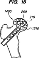
かくして、本明細書に開示する器具および方法は、例えば、椎骨圧迫骨折および脊椎湾曲の範疇における椎骨の整復および強化について説明したが、種々の他の用途および方法を考えることができる。例えば、或る実施形態では、移植可能なモノリシックチェーン200は、未だ圧迫または圧迫骨折が生じていない椎骨を強化するのに使用でき、従って本質的に予防処置にも使用できる。また或る実施形態では、チェーンは2つの椎骨の間に使用することもできる。例えば、チェーンインプラントは脊椎円板の環状体(annulus)内に挿入して円板を除去でき、隣接椎骨間に挿入されたチェーンインプラントは、隣接椎骨の融合を促進する。或る実施形態では、チェーンインプラントは、隣接椎骨間に移植されたケージのような付加インプラント内に挿入できる。チェーンインプラントはまた、図14に示すように、骨折または弱化した近位側大腿骨1400のような損傷を受けた他の骨領域を整復しおよび/または強化するのにも使用できる。このような実施形態では、例えば1つ以上のチェーン200が、例えば図15に示すようなカニューレ1102または他の導入器を通して大腿骨1400の頭部1410内に挿入される。ひとたび挿入されたならば、チェーン200は頭部1410内で材料を詰め込み、頭部1410を強化する中実支持体を形成する。この強化を補助するため、骨セメントまたはその他の充填材を使用することもできる。他の実施形態では、1つ以上のチェーン200に加えてまたはこれに代えて、他のインプラント1420を挿入できる。
Thus, while the devices and methods disclosed herein have been described for example in reducing and strengthening vertebrae in the category of vertebral compression fractures and spinal curvature, various other applications and methods can be envisaged. For example, in certain embodiments, the implantable
或る実施形態では、本明細書で説明するインプラントおよび方法は、他の器具および方法と組合せて使用し、脊椎前弯の修復および椎体の強化を行うことができる。例えば椎体の整復および/またはチェーン200のボディ内のスペースの形成を開始するのに使用される例えばバルーン脊椎後弯形成術のような既知の処置と組合せて使用することもできる。他の実施形態では、1つ以上のチェーン200を、椎骨または他の骨を操作して所望位置に固定する補助をなす他のツールまたは外部固定器具と組合せて使用することができる。
In certain embodiments, the implants and methods described herein can be used in combination with other instruments and methods to perform lordosis repair and vertebral body strengthening. It can also be used in combination with known procedures such as, for example, balloon kyphoplasty used to initiate vertebral body reduction and / or formation of a space within the body of
他の実施形態では、組立体およびコンポーネンツの種々の組合せからなるキットを構成できる。キットには、例えば、カニューレまたは他の導入器および1つ以上のフレキシブルモノリシックチェーン200を含めることができる。1つ以上のチェーン200は、異なるサイズ、例えば異なる長さおよび/または直径に形成できる。他の実施形態では、キットに、導入器、1つ以上のチェーン、および椎体または他のスペース内にセメントその他の充填材を注入するシリンジまたは他の器具を含めることができる。他の実施形態では、キットに、1つ以上のバルーンカテーテル、キューレットおよび他の器具を含めることができ、更に、例えば上記特許文献5に開示されているように、アンカーリング要素、テンショニング部材、固定部材またはこれらの任意の組合せを含めることができる。当業者ならば、器具、コンポーネンツおよび組立体の種々の他の組合せを考え得るであろうし、これらは本発明の範囲内に包含されるものである。
In other embodiments, kits comprising various combinations of assemblies and components can be constructed. The kit can include, for example, a cannula or other introducer and one or more flexible
他の実施形態では、脊柱に付随する不快感を緩和する種々の最小侵襲性インプラントおよび方法は、本明細書に開示するアンカーおよび他のインプラントを採用できる。例えば、拡大可能な容器(図示せず)内のモノリシックチェーンインプラントは、隣接椎骨の突起間に移植されて、突起を滑らかにしかつ例えば脊椎狭窄、小関節の関節症等により引起こされる痛みおよび他の問題を緩和する。例えば本明細書に開示の強化システムは、上記特許文献6および7に開示された拡大可能な椎骨間突起器具および方法の代わりにまたはこれらに加えて使用できる。例えば、カニューレは、フレキシブルチェーンが充填される容器を挿入して該容器を拡大しかくして隣接椎骨突起を所望距離に維持すべく、隣接椎骨突起間に横方向から挿入される。或いは、膨張可能なバルーン部分を備えたバルーン容器は、隣接椎骨突起を通して挿入されかつフレキシブルチェーンが充填されて、バルーンを所望サイズに拡大させ、隣接椎骨突起を所望距離に保持する。その後、バルーンがシールされかつカテーテルから取外される。フレキシブルボディを補足するため、他の材料をバルーン内に挿入することができる。 In other embodiments, various minimally invasive implants and methods for alleviating discomfort associated with the spinal column can employ the anchors and other implants disclosed herein. For example, a monolithic chain implant in an expandable container (not shown) can be implanted between adjacent vertebral processes to smooth the processes and cause pain and others caused by, for example, spinal stenosis, small joint arthropathy, etc. To alleviate the problem. For example, the enhancement system disclosed herein can be used in place of or in addition to the expandable intervertebral process devices and methods disclosed in US Pat. For example, a cannula is inserted laterally between adjacent vertebral processes to insert a container filled with a flexible chain to expand the container and thus maintain the adjacent vertebral process at a desired distance. Alternatively, a balloon container with an inflatable balloon portion is inserted through the adjacent vertebral process and filled with a flexible chain to expand the balloon to the desired size and hold the adjacent vertebral process at the desired distance. The balloon is then sealed and removed from the catheter. Other materials can be inserted into the balloon to supplement the flexible body.
以上、本発明の好ましい実施形態を説明しかつ図示したが、特許請求の範囲に記載の本発明の精神および範囲から逸脱することなく、種々の付加、変更および置換を行うことができる。特に、本発明は、その精神または本質的特徴から逸脱することなく、他の特定形態、構造、構成、割合で、かつ他の要素、材料およびコンポーネンツを用いて具現できる。従って、本願に開示した実施形態は全ての点で例示であって制限的なものではなく、本発明の範囲は、特許請求の範囲の記載により定められるものであって、上記説明に限定されるものではない。 While the preferred embodiment of the invention has been described and illustrated, various additions, changes and substitutions may be made without departing from the spirit and scope of the invention as set forth in the appended claims. In particular, the present invention may be embodied in other specific forms, structures, configurations, proportions and using other elements, materials and components without departing from its spirit or essential characteristics. Accordingly, the embodiments disclosed herein are illustrative and non-restrictive in every respect, and the scope of the present invention is defined by the description of the scope of claims and is limited to the above description. It is not a thing.
10 脊椎
12 椎体
200 チェーン
210 ボディ
220 リンキング部分(フレキシブル部分、ストラット)
320 脱ミネラル化溶液
510 キャビティ
602 カニューレ
604 ルーメン
812 プラグ
910 デリバリ器具
1110 ねじ機構
10
320
Claims (11)
第1横断面寸法を有する複数のボディと、
該複数のボディを相互連結する複数のリンクとを更に有し、前記ボディおよび前記リンクは端と端とが連結されて細長部材を形成し、前記リンクは、第2横断面寸法を有し、前記第1横断面寸法は、前記第2横断面寸法よりも大きく、前記細長部材は、骨で形成されており、前記リンクおよび前記ボディは、前記リンクが前記ボディよりも大きい程度脱ミネラル化されるように少なくとも部分的に脱ミネラル化されていることを特徴とする体組織強化器具。A flexible elongated member having a width, a height, and a longitudinal length substantially longer than the width or the height, wherein the flexible elongated member is formed as an integral monolithic elongated member;
A plurality of bodies having a first cross-sectional dimension;
A plurality of links interconnecting the plurality of bodies, the bodies and the links being connected end to end to form an elongated member, the links having a second cross-sectional dimension; The first cross-sectional dimension is greater than the second cross-sectional dimension, the elongate member is formed of bone, and the link and the body are demineralized to the extent that the link is larger than the body. A body tissue strengthening device characterized in that it is at least partially demineralized.
Applications Claiming Priority (5)
| Application Number | Priority Date | Filing Date | Title |
|---|---|---|---|
| US75378205P | 2005-12-23 | 2005-12-23 | |
| US60/753,782 | 2005-12-23 | ||
| US81045306P | 2006-06-02 | 2006-06-02 | |
| US60/810,453 | 2006-06-02 | ||
| PCT/US2006/049105 WO2007076049A2 (en) | 2005-12-23 | 2006-12-20 | Flexible elongated chain implant |
Publications (3)
| Publication Number | Publication Date |
|---|---|
| JP2009521279A JP2009521279A (en) | 2009-06-04 |
| JP2009521279A5 JP2009521279A5 (en) | 2010-02-12 |
| JP4990293B2 true JP4990293B2 (en) | 2012-08-01 |
Family
ID=38147568
Family Applications (1)
| Application Number | Title | Priority Date | Filing Date |
|---|---|---|---|
| JP2008547631A Expired - Fee Related JP4990293B2 (en) | 2005-12-23 | 2006-12-20 | Flexible elongated chain implant and method for supporting body tissue using the implant |
Country Status (12)
| Country | Link |
|---|---|
| US (7) | US20070162132A1 (en) |
| EP (1) | EP1962705B1 (en) |
| JP (1) | JP4990293B2 (en) |
| KR (1) | KR20080085058A (en) |
| AT (1) | ATE466532T1 (en) |
| AU (1) | AU2006330939A1 (en) |
| BR (1) | BRPI0620452A2 (en) |
| CA (1) | CA2634762C (en) |
| DE (1) | DE602006014202D1 (en) |
| ES (1) | ES2342117T3 (en) |
| PL (1) | PL1962705T3 (en) |
| WO (1) | WO2007076049A2 (en) |
Families Citing this family (109)
| Publication number | Priority date | Publication date | Assignee | Title |
|---|---|---|---|---|
| EP1624832A4 (en) | 1999-08-18 | 2008-12-24 | Intrinsic Therapeutics Inc | Devices and method for augmenting a vertebral disc nucleus |
| US7717961B2 (en) * | 1999-08-18 | 2010-05-18 | Intrinsic Therapeutics, Inc. | Apparatus delivery in an intervertebral disc |
| US7972337B2 (en) | 2005-12-28 | 2011-07-05 | Intrinsic Therapeutics, Inc. | Devices and methods for bone anchoring |
| US8323341B2 (en) | 2007-09-07 | 2012-12-04 | Intrinsic Therapeutics, Inc. | Impaction grafting for vertebral fusion |
| WO2002054978A2 (en) * | 1999-08-18 | 2002-07-18 | Intrinsic Orthopedics Inc | Devices and method for nucleus pulposus augmentation and retention |
| US20030055316A1 (en) * | 2001-09-19 | 2003-03-20 | Brannon James Kevin | Endoscopic bone debridement |
| ES2329665T3 (en) * | 2001-10-02 | 2009-11-30 | Rex Medical, L.P. | SPIRAL IMPLANT |
| DE10154163A1 (en) * | 2001-11-03 | 2003-05-22 | Advanced Med Tech | Device for straightening and stabilizing the spine |
| US7744597B2 (en) | 2002-06-26 | 2010-06-29 | Lifenet Health | Device and process for producing fiber products and fiber products produced thereby |
| WO2004019815A2 (en) * | 2002-08-27 | 2004-03-11 | Sdgi Holdings, Inc. | Systems and methods for intravertebral reduction |
| US7494811B2 (en) | 2003-05-01 | 2009-02-24 | Lifenet Health | In vitro growth of tissues suitable to the formation of bone and bone forming tissue formed thereby |
| AU2004274008A1 (en) * | 2003-09-19 | 2005-03-31 | Synecor, Llc | Method and apparatus for treating diseased or fractured bone |
| US8328876B2 (en) * | 2003-12-31 | 2012-12-11 | Warsaw Orthopedic, Inc. | Bone matrix compositions and methods |
| US7621952B2 (en) * | 2004-06-07 | 2009-11-24 | Dfine, Inc. | Implants and methods for treating bone |
| US7799078B2 (en) * | 2004-11-12 | 2010-09-21 | Warsaw Orthopedic, Inc. | Implantable vertebral lift |
| WO2006058221A2 (en) | 2004-11-24 | 2006-06-01 | Abdou Samy M | Devices and methods for inter-vertebral orthopedic device placement |
| US8911759B2 (en) | 2005-11-01 | 2014-12-16 | Warsaw Orthopedic, Inc. | Bone matrix compositions and methods |
| US20070162132A1 (en) | 2005-12-23 | 2007-07-12 | Dominique Messerli | Flexible elongated chain implant and method of supporting body tissue with same |
| WO2007089739A2 (en) | 2006-01-27 | 2007-08-09 | Stryker Corporation | Low pressure delivery system and method for delivering a solid and liquid mixture into a target site for medical treatment |
| US20070233249A1 (en) * | 2006-02-07 | 2007-10-04 | Shadduck John H | Methods for treating bone |
| US20080065083A1 (en) * | 2006-09-07 | 2008-03-13 | Csaba Truckai | Bone treatment systems and methods |
| US9724206B2 (en) * | 2006-09-20 | 2017-08-08 | Woodwelding Ag | Device to be implanted in human or animal tissue and method for implanting and assembling the device |
| US8137352B2 (en) * | 2006-10-16 | 2012-03-20 | Depuy Spine, Inc. | Expandable intervertebral tool system and method |
| CA2668655A1 (en) | 2006-11-16 | 2008-05-29 | Rex Medical, L.P. | Spinal implant and method of use |
| US8105382B2 (en) | 2006-12-07 | 2012-01-31 | Interventional Spine, Inc. | Intervertebral implant |
| US7824427B2 (en) * | 2007-01-16 | 2010-11-02 | Perez-Cruet Miquelangelo J | Minimally invasive interbody device |
| WO2008157492A2 (en) | 2007-06-15 | 2008-12-24 | Osteotech, Inc. | Osteoinductive demineralized cancellous bone |
| AU2008265850B2 (en) | 2007-06-15 | 2014-06-26 | Warsaw Orthopedic, Inc. | Bone matrix compositions and methods |
| AU2008265852B2 (en) | 2007-06-15 | 2014-04-17 | Warsaw Orthopedic, Inc. | Method of treating tissue |
| US9554920B2 (en) | 2007-06-15 | 2017-01-31 | Warsaw Orthopedic, Inc. | Bone matrix compositions having nanoscale textured surfaces |
| US8900307B2 (en) | 2007-06-26 | 2014-12-02 | DePuy Synthes Products, LLC | Highly lordosed fusion cage |
| AU2008269985A1 (en) * | 2007-06-29 | 2009-01-08 | Synthes Gmbh | Improved orthopedic implants for use with precision bone resurfacing instrumentation |
| WO2009006432A2 (en) * | 2007-06-29 | 2009-01-08 | Synthes (U.S.A.) | Flexible chain implants and instrumentation |
| US9358113B2 (en) | 2007-07-10 | 2016-06-07 | Warsaw Orthopedic, Inc. | Delivery system |
| US20110196492A1 (en) * | 2007-09-07 | 2011-08-11 | Intrinsic Therapeutics, Inc. | Bone anchoring systems |
| JP5331810B2 (en) * | 2007-09-11 | 2013-10-30 | ジョイ メディカル デバイスズ コーポレーション | System for forming a cavity in bone and method for recovering beads by magnetic force |
| US7972380B2 (en) * | 2007-09-17 | 2011-07-05 | Linares Medical Devices, Llc | Artificial joint support between first and second bones |
| AU2008311785A1 (en) | 2007-10-19 | 2009-04-23 | Warsaw Orthopedic, Inc. | Demineralized bone matrix compositions and methods |
| WO2009092102A1 (en) | 2008-01-17 | 2009-07-23 | Synthes Usa, Llc | An expandable intervertebral implant and associated method of manufacturing the same |
| EP2262449B1 (en) | 2008-04-05 | 2020-03-11 | Synthes GmbH | Expandable intervertebral implant |
| BRPI0914950A2 (en) | 2008-06-19 | 2015-10-20 | Synthes Gmbh | implants, systems and techniques for increasing the mechanical advantage of bone screws |
| WO2010093955A1 (en) * | 2009-02-12 | 2010-08-19 | Osteotech,Inc. | Segmented delivery system |
| US9526620B2 (en) | 2009-03-30 | 2016-12-27 | DePuy Synthes Products, Inc. | Zero profile spinal fusion cage |
| DE102009025297A1 (en) * | 2009-06-15 | 2010-12-16 | Heraeus Medical Gmbh | Medical system |
| US9028553B2 (en) | 2009-11-05 | 2015-05-12 | DePuy Synthes Products, Inc. | Self-pivoting spinal implant and associated instrumentation |
| US8764806B2 (en) | 2009-12-07 | 2014-07-01 | Samy Abdou | Devices and methods for minimally invasive spinal stabilization and instrumentation |
| US9393129B2 (en) | 2009-12-10 | 2016-07-19 | DePuy Synthes Products, Inc. | Bellows-like expandable interbody fusion cage |
| US9220554B2 (en) | 2010-02-18 | 2015-12-29 | Globus Medical, Inc. | Methods and apparatus for treating vertebral fractures |
| US8845733B2 (en) | 2010-06-24 | 2014-09-30 | DePuy Synthes Products, LLC | Lateral spondylolisthesis reduction cage |
| US8979860B2 (en) | 2010-06-24 | 2015-03-17 | DePuy Synthes Products. LLC | Enhanced cage insertion device |
| EP2588034B1 (en) | 2010-06-29 | 2018-01-03 | Synthes GmbH | Distractible intervertebral implant |
| US8795369B1 (en) | 2010-07-16 | 2014-08-05 | Nuvasive, Inc. | Fracture reduction device and methods |
| US9402732B2 (en) | 2010-10-11 | 2016-08-02 | DePuy Synthes Products, Inc. | Expandable interspinous process spacer implant |
| WO2012061024A1 (en) * | 2010-10-25 | 2012-05-10 | Musculoskeletal Transplant Foundation | Demineralized cortical bone implants |
| US8512408B2 (en) | 2010-12-17 | 2013-08-20 | Warsaw Orthopedic, Inc. | Flexiable spinal implant |
| WO2012129197A1 (en) | 2011-03-22 | 2012-09-27 | Depuy Spine, Inc. | Universal trial for lateral cages |
| US20130018467A1 (en) * | 2011-07-15 | 2013-01-17 | Sean Suh | Systems and Methods For Vertebral Body and Disc Height Restoration |
| US8845728B1 (en) | 2011-09-23 | 2014-09-30 | Samy Abdou | Spinal fixation devices and methods of use |
| AU2012339536B2 (en) | 2011-11-14 | 2016-02-11 | British Columbia Cancer Agency Branch | Intramedullary fixation system for management of pelvic and acetabular fractures |
| WO2013116452A2 (en) * | 2012-01-31 | 2013-08-08 | The University Of Toledo | Bioactive fusion device |
| US20130226240A1 (en) | 2012-02-22 | 2013-08-29 | Samy Abdou | Spinous process fixation devices and methods of use |
| US9226764B2 (en) | 2012-03-06 | 2016-01-05 | DePuy Synthes Products, Inc. | Conformable soft tissue removal instruments |
| PL219189B1 (en) | 2012-03-06 | 2015-03-31 | Lfc Spółka Z Ograniczoną Odpowiedzialnością | Interbody distance device for entering the biomaterial to the vertebral body and the application of the device |
| BR112014029904A2 (en) | 2012-05-29 | 2017-06-27 | Nlt Spine Ltd | laterally deflectable implant, assembly and method for implantation into a body |
| US9585764B2 (en) * | 2012-07-26 | 2017-03-07 | Warsaw Orthopedic, Inc. | Bone implant device |
| US9198767B2 (en) | 2012-08-28 | 2015-12-01 | Samy Abdou | Devices and methods for spinal stabilization and instrumentation |
| US9320617B2 (en) | 2012-10-22 | 2016-04-26 | Cogent Spine, LLC | Devices and methods for spinal stabilization and instrumentation |
| US10022245B2 (en) | 2012-12-17 | 2018-07-17 | DePuy Synthes Products, Inc. | Polyaxial articulating instrument |
| EP2958536A4 (en) | 2013-02-22 | 2017-06-21 | Lifenet Health | Packaging assembly for storing tissue and cellular material |
| US9522070B2 (en) | 2013-03-07 | 2016-12-20 | Interventional Spine, Inc. | Intervertebral implant |
| US9358120B2 (en) | 2013-03-14 | 2016-06-07 | DePuy Synthes Products, Inc. | Expandable coil spinal implant |
| US9585761B2 (en) | 2013-03-14 | 2017-03-07 | DePuy Synthes Products, Inc. | Angulated rings and bonded foils for use with balloons for fusion and dynamic stabilization |
| US9572676B2 (en) | 2013-03-14 | 2017-02-21 | DePuy Synthes Products, Inc. | Adjustable multi-volume balloon for spinal interventions |
| EP2777628B1 (en) | 2013-03-15 | 2018-02-28 | Neos Surgery, S.L. | Device for repairing an intervertebral disc |
| US9937052B2 (en) | 2013-03-15 | 2018-04-10 | Cogent Spine Llc | Methods and apparatus for implanting an interbody device |
| US9278002B2 (en) * | 2013-06-07 | 2016-03-08 | Gregory Merrell | Elbow antibiotic spacer implant |
| CA2978697A1 (en) | 2014-03-06 | 2015-09-11 | The University Of British Columbia | Shape adaptable intramedullary fixation device |
| US10376648B1 (en) * | 2014-08-11 | 2019-08-13 | H & M Innovations, Llc | Bone delivery apparatus and methods |
| CN104207829A (en) * | 2014-09-03 | 2014-12-17 | 吉林大学 | Antibiotic bone cement chain bead manufacturer and method |
| EP3206608B1 (en) | 2014-10-14 | 2023-07-05 | The University of British Columbia | Systems for intramedullary bone fixation |
| CN107405201B (en) * | 2015-01-09 | 2020-10-27 | 孚美公司 | Rigid segmented flexible anchor |
| GB2535487A (en) * | 2015-02-17 | 2016-08-24 | Biocomposites Ltd | Device to fill a bone void whilst minimising pressurisation |
| US11426290B2 (en) | 2015-03-06 | 2022-08-30 | DePuy Synthes Products, Inc. | Expandable intervertebral implant, system, kit and method |
| US10952856B2 (en) * | 2015-04-15 | 2021-03-23 | FreeseTEC Corporation | Spinal fusion containment system |
| DE102015110202B3 (en) * | 2015-06-25 | 2016-06-09 | Heraeus Medical Gmbh | Kit for constructing a cage for spinal fusion and method therefor and corresponding cage and its use |
| US10857003B1 (en) | 2015-10-14 | 2020-12-08 | Samy Abdou | Devices and methods for vertebral stabilization |
| TWI576085B (en) * | 2016-02-01 | 2017-04-01 | 愛派司生技股份有限公司 | A securing device for a long bone |
| CN109688980B (en) | 2016-06-28 | 2022-06-10 | Eit 新兴移植技术股份有限公司 | Expandable and angularly adjustable intervertebral cage with articulation joint |
| JP6995789B2 (en) | 2016-06-28 | 2022-01-17 | イーアイティー・エマージング・インプラント・テクノロジーズ・ゲーエムベーハー | Expandable and angle adjustable intervertebral cage |
| EP3522803A4 (en) | 2016-10-05 | 2020-05-27 | The University of British Columbia | Intramedullary fixation device with shape locking interface |
| US10744000B1 (en) | 2016-10-25 | 2020-08-18 | Samy Abdou | Devices and methods for vertebral bone realignment |
| US10973648B1 (en) | 2016-10-25 | 2021-04-13 | Samy Abdou | Devices and methods for vertebral bone realignment |
| US9974655B1 (en) * | 2016-12-19 | 2018-05-22 | Perumala Corporation | Disc and vertebral defect packing tape |
| US10342663B2 (en) | 2016-12-19 | 2019-07-09 | Perumala Corporation | Disc and vertebral defect packing tape |
| US10398563B2 (en) | 2017-05-08 | 2019-09-03 | Medos International Sarl | Expandable cage |
| AR108432A1 (en) * | 2017-05-10 | 2018-08-22 | Jorge Alberto Vanetta | BONE FILLING AND BONE FILLING DEVICE; AUXILIARY TOOL AND PLACEMENT AND FILLING METHODS |
| US11344424B2 (en) | 2017-06-14 | 2022-05-31 | Medos International Sarl | Expandable intervertebral implant and related methods |
| US10966843B2 (en) | 2017-07-18 | 2021-04-06 | DePuy Synthes Products, Inc. | Implant inserters and related methods |
| US11045331B2 (en) | 2017-08-14 | 2021-06-29 | DePuy Synthes Products, Inc. | Intervertebral implant inserters and related methods |
| US10932839B2 (en) | 2017-12-19 | 2021-03-02 | Stryker Corporation | Systems and methods for delivering elements within a fluent material to an off-axis target site within a bone structure |
| US11179248B2 (en) | 2018-10-02 | 2021-11-23 | Samy Abdou | Devices and methods for spinal implantation |
| EP3866713A4 (en) | 2018-10-17 | 2022-06-29 | The University of British Columbia | Bone-fixation device and system |
| US11446156B2 (en) | 2018-10-25 | 2022-09-20 | Medos International Sarl | Expandable intervertebral implant, inserter instrument, and related methods |
| US11426286B2 (en) | 2020-03-06 | 2022-08-30 | Eit Emerging Implant Technologies Gmbh | Expandable intervertebral implant |
| US11850160B2 (en) | 2021-03-26 | 2023-12-26 | Medos International Sarl | Expandable lordotic intervertebral fusion cage |
| US11752009B2 (en) | 2021-04-06 | 2023-09-12 | Medos International Sarl | Expandable intervertebral fusion cage |
| US20220409387A1 (en) * | 2021-06-23 | 2022-12-29 | Oluwatodimu Richard Raji | Methods and systems for facilitating treatment of lumbar degenerative disc disease based on total nucleus replacement using magnetic spherical beads |
| US20230355405A1 (en) * | 2022-05-04 | 2023-11-09 | NovApproach Spine, LLC | Interbody cage device and method for performing spinal surgical procedures |
| CN116807695B (en) * | 2023-08-29 | 2023-12-19 | 北京爱康宜诚医疗器材有限公司 | Hip joint prosthesis |
Family Cites Families (242)
| Publication number | Priority date | Publication date | Assignee | Title |
|---|---|---|---|---|
| US2381050A (en) | 1943-12-04 | 1945-08-07 | Mervyn G Hardinge | Fracture reducing device |
| US3034110A (en) | 1958-06-30 | 1962-05-08 | Ibm | Support device |
| US3007535A (en) | 1960-10-31 | 1961-11-07 | Deere & Co | Implement attaching means |
| FR2287894A1 (en) | 1974-10-15 | 1976-05-14 | Roussel Uclaf | Automatic pellet implanting device - for subcutaneous introduction of prods into animals |
| US4611581A (en) | 1983-12-16 | 1986-09-16 | Acromed Corporation | Apparatus for straightening spinal columns |
| US5522894A (en) | 1984-12-14 | 1996-06-04 | Draenert; Klaus | Bone replacement material made of absorbable beads |
| US5053049A (en) | 1985-05-29 | 1991-10-01 | Baxter International | Flexible prostheses of predetermined shapes and process for making same |
| US4839215A (en) * | 1986-06-09 | 1989-06-13 | Ceramed Corporation | Biocompatible particles and cloth-like article made therefrom |
| US4776330A (en) | 1986-06-23 | 1988-10-11 | Pfizer Hospital Products Group, Inc. | Modular femoral fixation system |
| GB8620937D0 (en) | 1986-08-29 | 1986-10-08 | Shepperd J A N | Spinal implant |
| US4820349A (en) | 1987-08-21 | 1989-04-11 | C. R. Bard, Inc. | Dilatation catheter with collapsible outer diameter |
| US5484437A (en) | 1988-06-13 | 1996-01-16 | Michelson; Gary K. | Apparatus and method of inserting spinal implants |
| CA1333209C (en) | 1988-06-28 | 1994-11-29 | Gary Karlin Michelson | Artificial spinal fusion implants |
| US4969888A (en) | 1989-02-09 | 1990-11-13 | Arie Scholten | Surgical protocol for fixation of osteoporotic bone using inflatable device |
| US5759191A (en) | 1989-06-27 | 1998-06-02 | C. R. Bard, Inc. | Coaxial PTCA catheter with anchor joint |
| US6179856B1 (en) | 1989-07-05 | 2001-01-30 | Medtronic Ave, Inc. | Coaxial PTCA catheter with anchor joint |
| US5290558A (en) | 1989-09-21 | 1994-03-01 | Osteotech, Inc. | Flowable demineralized bone powder composition and its use in bone repair |
| US5059193A (en) | 1989-11-20 | 1991-10-22 | Spine-Tech, Inc. | Expandable spinal implant and surgical method |
| IT1244249B (en) | 1990-08-03 | 1994-07-08 | Ascanio Campopiano | MANIPULATOR FOR THE EXECUTION OF REDUCING MANEUVERS IN USE IN TRAUMATOLOGICAL AND ORTHOPEDIC MEDICINE APPLICABLE TO EXTERNAL FIXATORS. |
| US5372146A (en) | 1990-11-06 | 1994-12-13 | Branch; Thomas P. | Method and apparatus for re-approximating tissue |
| CS277533B6 (en) | 1990-12-29 | 1993-03-17 | Krajicek Milan | Fixed osteaosynthesis appliance |
| US5123926A (en) | 1991-02-22 | 1992-06-23 | Madhavan Pisharodi | Artificial spinal prosthesis |
| WO1992014423A1 (en) | 1991-02-22 | 1992-09-03 | Pisharodi Madhavan | Middle expandable intervertebral disk implant and method |
| NL9101197A (en) | 1991-07-08 | 1993-02-01 | Texas Instruments Holland | INJECTOR. |
| DE4200905A1 (en) | 1992-01-16 | 1993-07-22 | Heinrich Ulrich | IMPLANT FOR ALIGNMENT AND FIXING OF TWO BONES OR BONE PARTS TOGETHER, IN PARTICULAR SPONDYLODESE IMPLANT |
| NL9200288A (en) | 1992-02-17 | 1993-09-16 | Acromed Bv | DEVICE FOR FIXING AT LEAST A PART OF THE CERVICAL AND / OR THORACAL SPIRIT COLUMN. |
| EP0582857B1 (en) | 1992-08-12 | 1997-02-05 | Synthes AG, Chur | Spinal fixation element |
| US5534023A (en) | 1992-12-29 | 1996-07-09 | Henley; Julian L. | Fluid filled prosthesis excluding gas-filled beads |
| EP0621020A1 (en) * | 1993-04-21 | 1994-10-26 | SULZER Medizinaltechnik AG | Intervertebral prosthesis and method of implanting such a prosthesis |
| US7044954B2 (en) | 1994-01-26 | 2006-05-16 | Kyphon Inc. | Method for treating a vertebral body |
| US6248110B1 (en) | 1994-01-26 | 2001-06-19 | Kyphon, Inc. | Systems and methods for treating fractured or diseased bone using expandable bodies |
| EP1464293B1 (en) | 1994-01-26 | 2007-05-02 | Kyphon Inc. | Improved inflatable device for use in surgical methods relating to fixation of bone |
| US6241734B1 (en) | 1998-08-14 | 2001-06-05 | Kyphon, Inc. | Systems and methods for placing materials into bone |
| JP3333211B2 (en) | 1994-01-26 | 2002-10-15 | レイリー,マーク・エイ | Improved expandable device for use in a surgical method for bone treatment |
| US7166121B2 (en) | 1994-01-26 | 2007-01-23 | Kyphon Inc. | Systems and methods using expandable bodies to push apart cortical bone surfaces |
| US20030032963A1 (en) | 2001-10-24 | 2003-02-13 | Kyphon Inc. | Devices and methods using an expandable body with internal restraint for compressing cancellous bone |
| US5697977A (en) | 1994-03-18 | 1997-12-16 | Pisharodi; Madhavan | Method and apparatus for spondylolisthesis reduction |
| US5571189A (en) | 1994-05-20 | 1996-11-05 | Kuslich; Stephen D. | Expandable fabric implant for stabilizing the spinal motion segment |
| EP0700671B1 (en) | 1994-09-08 | 2001-08-08 | Stryker Technologies Corporation | Hydrogel intervertebral disc nucleus |
| US5665122A (en) | 1995-01-31 | 1997-09-09 | Kambin; Parviz | Expandable intervertebral cage and surgical method |
| US5637042A (en) | 1995-03-21 | 1997-06-10 | Dana Corporation | Drive line assembly with reducing tube yoke |
| FR2735354B1 (en) | 1995-06-13 | 1997-08-14 | Perouse Implant Lab | BREAST PROSTHESIS |
| US6183768B1 (en) | 1995-07-26 | 2001-02-06 | HäRLE ANTON | Implantable medicine releasing corpuscles and method of making, implanting and removing the same |
| ATE349190T1 (en) | 1995-11-08 | 2007-01-15 | Zimmer Gmbh | DEVICE FOR INSERTING AN IMPLANT, IN PARTICULAR AN INTERVERBAL PROSTHESIS |
| DE19606490A1 (en) | 1996-02-22 | 1997-08-28 | Merck Patent Gmbh | Device for the manual production of pearl cord-shaped pharmaceutical implants |
| US5868749A (en) | 1996-04-05 | 1999-02-09 | Reed; Thomas M. | Fixation devices |
| US5690678A (en) | 1996-04-30 | 1997-11-25 | Johnson; Lanny L. | Arrangement for anchoring suture to bone |
| US6491714B1 (en) | 1996-05-03 | 2002-12-10 | William F. Bennett | Surgical tissue repair and attachment apparatus and method |
| US6189537B1 (en) | 1996-09-06 | 2001-02-20 | Lifenet | Process for producing osteoinductive bone, and osteoinductive bone produced thereby |
| US5716416A (en) * | 1996-09-10 | 1998-02-10 | Lin; Chih-I | Artificial intervertebral disk and method for implanting the same |
| US5878886A (en) | 1996-09-20 | 1999-03-09 | Marshall; John C. | Display package for pull chains and the like |
| US5756127A (en) | 1996-10-29 | 1998-05-26 | Wright Medical Technology, Inc. | Implantable bioresorbable string of calcium sulfate beads |
| US5782831A (en) | 1996-11-06 | 1998-07-21 | Sdgi Holdings, Inc. | Method an device for spinal deformity reduction using a cable and a cable tensioning system |
| EP1230902A1 (en) | 1996-11-15 | 2002-08-14 | Advanced Bio Surfaces, Inc. | Biomaterial system for in situ tissue repair |
| US5961554A (en) * | 1996-12-31 | 1999-10-05 | Janson; Frank S | Intervertebral spacer |
| US5836948A (en) | 1997-01-02 | 1998-11-17 | Saint Francis Medical Technologies, Llc | Spine distraction implant and method |
| US20060271061A1 (en) | 2001-07-25 | 2006-11-30 | Disc-O-Tech, Ltd. | Deformable tools and implants |
| JP2001527437A (en) | 1997-03-07 | 2001-12-25 | ベイヤー、モルデキイ | System for percutaneous bone and spine stabilization, fixation and repair |
| WO2001054598A1 (en) | 1998-03-06 | 2001-08-02 | Disc-O-Tech Medical Technologies, Ltd. | Expanding bone implants |
| IL128261A0 (en) | 1999-01-27 | 1999-11-30 | Disc O Tech Medical Tech Ltd | Expandable element |
| DE19710392C1 (en) | 1997-03-13 | 1999-07-01 | Haehnel Michael | Slipped disc implant comprises an extensible, hinged or wound body |
| US6045579A (en) | 1997-05-01 | 2000-04-04 | Spinal Concepts, Inc. | Adjustable height fusion device |
| US6149651A (en) | 1997-06-02 | 2000-11-21 | Sdgi Holdings, Inc. | Device for supporting weak bony structures |
| US5972015A (en) | 1997-08-15 | 1999-10-26 | Kyphon Inc. | Expandable, asymetric structures for deployment in interior body regions |
| US6048346A (en) | 1997-08-13 | 2000-04-11 | Kyphon Inc. | Systems and methods for injecting flowable materials into bones |
| US5865848A (en) | 1997-09-12 | 1999-02-02 | Artifex, Ltd. | Dynamic intervertebral spacer and method of use |
| JP2001516618A (en) * | 1997-09-17 | 2001-10-02 | オステオテック インコーポレーテッド | Fusion transplantation device and method of using the same |
| US6652592B1 (en) | 1997-10-27 | 2003-11-25 | Regeneration Technologies, Inc. | Segmentally demineralized bone implant |
| US6090998A (en) | 1997-10-27 | 2000-07-18 | University Of Florida | Segmentally demineralized bone implant |
| US20010001129A1 (en) | 1997-12-10 | 2001-05-10 | Mckay William F. | Osteogenic fusion device |
| US5899939A (en) | 1998-01-21 | 1999-05-04 | Osteotech, Inc. | Bone-derived implant for load-supporting applications |
| US7087082B2 (en) | 1998-08-03 | 2006-08-08 | Synthes (Usa) | Bone implants with central chambers |
| US6290718B1 (en) | 1998-02-02 | 2001-09-18 | Regeneration Technologies, Inc. | Luminal graft, stent or conduit made of cortical bone |
| DE19807236C2 (en) | 1998-02-20 | 2000-06-21 | Biedermann Motech Gmbh | Intervertebral implant |
| WO1999049818A1 (en) | 1998-03-30 | 1999-10-07 | Marchosky J Alexander | Prosthetic system |
| US6835208B2 (en) | 1998-03-30 | 2004-12-28 | J. Alexander Marchosky | Prosthetic system |
| US6440138B1 (en) | 1998-04-06 | 2002-08-27 | Kyphon Inc. | Structures and methods for creating cavities in interior body regions |
| US6126689A (en) | 1998-06-15 | 2000-10-03 | Expanding Concepts, L.L.C. | Collapsible and expandable interbody fusion device |
| US6293970B1 (en) | 1998-06-30 | 2001-09-25 | Lifenet | Plasticized bone and soft tissue grafts and methods of making and using same |
| US6162231A (en) | 1998-09-14 | 2000-12-19 | Endocare, Inc. | Stent insertion device |
| US6497726B1 (en) | 2000-01-11 | 2002-12-24 | Regeneration Technologies, Inc. | Materials and methods for improved bone tendon bone transplantation |
| US6206923B1 (en) | 1999-01-08 | 2001-03-27 | Sdgi Holdings, Inc. | Flexible implant using partially demineralized bone |
| CA2363254C (en) | 1999-03-07 | 2009-05-05 | Discure Ltd. | Method and apparatus for computerized surgery |
| US6602291B1 (en) | 1999-04-05 | 2003-08-05 | Raymedica, Inc. | Prosthetic spinal disc nucleus having a shape change characteristic |
| US6332887B1 (en) | 1999-04-06 | 2001-12-25 | Benjamin D. Knox | Spinal fusion instrumentation system |
| AU4246000A (en) * | 1999-04-16 | 2000-11-02 | Nuvasive, Inc. | Articulation systems for positioning minimally invasive surgical tools |
| AU4810800A (en) | 1999-04-26 | 2000-11-10 | Li Medical Technologies, Inc. | Prosthetic apparatus and method |
| US6969404B2 (en) | 1999-10-08 | 2005-11-29 | Ferree Bret A | Annulus fibrosis augmentation methods and apparatus |
| FR2794362B1 (en) | 1999-06-02 | 2001-09-21 | Henry Graf | INTERVERTEBRAL IMPLANT AND POSITIONING ASSEMBLY OF SUCH AN IMPLANT |
| AU5701200A (en) | 1999-07-02 | 2001-01-22 | Petrus Besselink | Reinforced expandable cage |
| US7226475B2 (en) | 1999-11-09 | 2007-06-05 | Boston Scientific Scimed, Inc. | Stent with variable properties |
| JP4162408B2 (en) | 2000-01-27 | 2008-10-08 | ジンテーズ ゲゼルシャフト ミト ベシュレンクテル ハフツング | Bone plate |
| WO2001078798A1 (en) | 2000-02-10 | 2001-10-25 | Regeneration Technologies, Inc. | Assembled implant |
| US6332894B1 (en) | 2000-03-07 | 2001-12-25 | Zimmer, Inc. | Polymer filled spinal fusion cage |
| AR027685A1 (en) | 2000-03-22 | 2003-04-09 | Synthes Ag | METHOD AND METHOD FOR CARRYING OUT |
| ATE318559T1 (en) | 2000-04-05 | 2006-03-15 | Kyphon Inc | DEVICES FOR TREATING BROKEN AND/OR DISEASE BONES |
| US6340477B1 (en) | 2000-04-27 | 2002-01-22 | Lifenet | Bone matrix composition and methods for making and using same |
| US6869445B1 (en) | 2000-05-04 | 2005-03-22 | Phillips Plastics Corp. | Packable ceramic beads for bone repair |
| EP1280564B1 (en) | 2000-05-12 | 2005-08-31 | Osteotech, Inc. | Surface demineralized osteoimplant and method for making same |
| US7025771B2 (en) | 2000-06-30 | 2006-04-11 | Spineology, Inc. | Tool to direct bone replacement material |
| US20020068974A1 (en) | 2000-07-21 | 2002-06-06 | Kuslich Stephen D. | Expandable porous mesh bag device and methods of use for reduction, filling, fixation and supporting of bone |
| EP1563808B1 (en) * | 2000-08-30 | 2008-04-02 | Warsaw Orthopedic, Inc. | Intervertebral disc nucleus implants |
| US7204851B2 (en) | 2000-08-30 | 2007-04-17 | Sdgi Holdings, Inc. | Method and apparatus for delivering an intervertebral disc implant |
| US20050154463A1 (en) * | 2000-08-30 | 2005-07-14 | Trieu Hal H. | Spinal nucleus replacement implants and methods |
| US6679886B2 (en) | 2000-09-01 | 2004-01-20 | Synthes (Usa) | Tools and methods for creating cavities in bone |
| US6761738B1 (en) * | 2000-09-19 | 2004-07-13 | Sdgi Holdings, Inc. | Reinforced molded implant formed of cortical bone |
| US6277120B1 (en) | 2000-09-20 | 2001-08-21 | Kevin Jon Lawson | Cable-anchor system for spinal fixation |
| CA2323252C (en) | 2000-10-12 | 2007-12-11 | Biorthex Inc. | Artificial disc |
| US6733531B1 (en) | 2000-10-20 | 2004-05-11 | Sdgi Holdings, Inc. | Anchoring devices and implants for intervertebral disc augmentation |
| KR100631787B1 (en) | 2000-12-15 | 2006-10-11 | 스파인올로지,인코포레이티드 | Spine Segment Stabilizer |
| JP2004518466A (en) | 2001-02-02 | 2004-06-24 | テクノロジィ ファイナンス コーポレイション(プロプライエタリー) リミテッド | Bone filler material |
| CA2437763C (en) * | 2001-02-12 | 2011-08-16 | Regeneration Technologies, Inc. | Assembled implant, including mixed-composition segment |
| US6827743B2 (en) | 2001-02-28 | 2004-12-07 | Sdgi Holdings, Inc. | Woven orthopedic implants |
| US6855169B2 (en) * | 2001-02-28 | 2005-02-15 | Synthes (Usa) | Demineralized bone-derived implants |
| US6595998B2 (en) * | 2001-03-08 | 2003-07-22 | Spinewave, Inc. | Tissue distraction device |
| US6849093B2 (en) | 2001-03-09 | 2005-02-01 | Gary K. Michelson | Expansion constraining member adapted for use with an expandable interbody spinal fusion implant and method for use thereof |
| US6802844B2 (en) | 2001-03-26 | 2004-10-12 | Nuvasive, Inc | Spinal alignment apparatus and methods |
| US6641583B2 (en) | 2001-03-29 | 2003-11-04 | Endius Incorporated | Apparatus for retaining bone portions in a desired spatial relationship |
| US7857860B2 (en) | 2003-04-30 | 2010-12-28 | Therics, Llc | Bone void filler and method of manufacture |
| US20050209629A1 (en) * | 2001-04-19 | 2005-09-22 | Kerr Sean H | Resorbable containment device and process for making and using same |
| US6632235B2 (en) * | 2001-04-19 | 2003-10-14 | Synthes (U.S.A.) | Inflatable device and method for reducing fractures in bone and in treating the spine |
| US6620162B2 (en) | 2001-07-20 | 2003-09-16 | Spineology, Inc. | Device for inserting fill material particles into body cavities |
| US20030028251A1 (en) | 2001-07-30 | 2003-02-06 | Mathews Hallett H. | Methods and devices for interbody spinal stabilization |
| US6706069B2 (en) | 2001-09-13 | 2004-03-16 | J. Lee Berger | Spinal grooved director with built in balloon |
| US6648891B2 (en) | 2001-09-14 | 2003-11-18 | The Regents Of The University Of California | System and method for fusing spinal vertebrae |
| ES2329665T3 (en) * | 2001-10-02 | 2009-11-30 | Rex Medical, L.P. | SPIRAL IMPLANT |
| DE10152094C2 (en) | 2001-10-23 | 2003-11-27 | Biedermann Motech Gmbh | Bone fixation device |
| DE10154163A1 (en) | 2001-11-03 | 2003-05-22 | Advanced Med Tech | Device for straightening and stabilizing the spine |
| US20030139812A1 (en) | 2001-11-09 | 2003-07-24 | Javier Garcia | Spinal implant |
| CZ2004681A3 (en) | 2001-12-05 | 2005-02-16 | Mathys Medizinaltechnik Ag | Intervertebral disk prosthesis or nucleus replacement prosthesis |
| DE10223332A1 (en) | 2002-05-25 | 2003-12-04 | Efmt Entwicklungs Und Forschun | Medical implant |
| JP4179495B2 (en) | 2002-06-12 | 2008-11-12 | 松崎 浩巳 | Bone filling material |
| US6793678B2 (en) | 2002-06-27 | 2004-09-21 | Depuy Acromed, Inc. | Prosthetic intervertebral motion disc having dampening |
| US7060066B2 (en) | 2002-06-28 | 2006-06-13 | Mayo Foundation For Medical Education And Research | Spinal fixation support device and methods of using |
| US7332138B2 (en) | 2002-07-26 | 2008-02-19 | Exxonmobil Research And Engineering Company | Jet mixing of process fluids in fixed bed reactor |
| US7101400B2 (en) | 2002-08-19 | 2006-09-05 | Jeffery Thramann | Shaped memory artificial disc and methods of engrafting the same |
| WO2004019815A2 (en) | 2002-08-27 | 2004-03-11 | Sdgi Holdings, Inc. | Systems and methods for intravertebral reduction |
| US20040087947A1 (en) | 2002-08-28 | 2004-05-06 | Roy Lim | Minimally invasive expanding spacer and method |
| CA2499116A1 (en) | 2002-09-18 | 2004-04-01 | Sdgi Holdings, Inc. | Natural tissue devices and methods of implantation |
| EP1567069A4 (en) | 2002-11-08 | 2008-11-12 | Warsaw Orthopedic Inc | Transpedicular intervertebral disk access methods and devices |
| AU2003279506A1 (en) | 2002-11-12 | 2004-06-03 | Regenex Ltd. | Expandable devices and methods for tissue expansion, regenerationand fixation |
| WO2004047689A1 (en) | 2002-11-21 | 2004-06-10 | Sdgi Holdings, Inc. | Systems and techniques for intravertebral spinal stablization with expandable devices |
| US7828849B2 (en) | 2003-02-03 | 2010-11-09 | Warsaw Orthopedic, Inc. | Expanding interbody implant and articulating inserter and method |
| CA2515862A1 (en) | 2003-02-14 | 2004-09-02 | Depuy Spine, Inc. | In-situ formed intervertebral fusion device |
| DE20303642U1 (en) | 2003-02-28 | 2003-04-30 | Aesculap Ag & Co Kg | Implant for reconstruction of human vertebra which has lost some of its load-carrying capacity or is broken consists of edgeless implant elements introduced singly |
| US7608096B2 (en) | 2003-03-10 | 2009-10-27 | Warsaw Orthopedic, Inc. | Posterior pedicle screw and plate system and methods |
| WO2004082526A2 (en) | 2003-03-14 | 2004-09-30 | Schneiderman Gary A | Intervertebral disk nuclear augmentation system |
| IL155146A0 (en) | 2003-03-30 | 2003-10-31 | Expandis Ltd | Minimally invasive distraction device and method |
| US7416553B2 (en) | 2003-04-09 | 2008-08-26 | Depuy Acromed, Inc. | Drill guide and plate inserter |
| TWI221091B (en) | 2003-04-18 | 2004-09-21 | A Spine Holding Group Corp | Spine filling device |
| TW587933B (en) | 2003-04-30 | 2004-05-21 | A Spine Holding Group Corp | Device for anchoring bone tissue |
| KR20060021875A (en) * | 2003-06-02 | 2006-03-08 | 에스디지아이 홀딩스 인코포레이티드 | Intervertebral disc implants and methods for manufacturing and using same |
| US7537617B2 (en) | 2003-06-05 | 2009-05-26 | Warsaw Orthopedic, Inc. | Bone strip implants and method of making same |
| US7351262B2 (en) * | 2003-06-05 | 2008-04-01 | Warsaw Orthopedic, Inc. | Bone implants and methods of making same |
| US20050015148A1 (en) | 2003-07-18 | 2005-01-20 | Jansen Lex P. | Biocompatible wires and methods of using same to fill bone void |
| US20050021040A1 (en) | 2003-07-21 | 2005-01-27 | Rudolf Bertagnoli | Vertebral retainer-distracter and method of using same |
| WO2005009299A1 (en) | 2003-07-25 | 2005-02-03 | Impliant Ltd. | Elastomeric spinal disc nucleus replacement |
| US6958077B2 (en) | 2003-07-29 | 2005-10-25 | Loubert Suddaby | Inflatable nuclear prosthesis |
| WO2005018468A2 (en) * | 2003-08-11 | 2005-03-03 | Wilson-Cook Medical Inc. | Surgical implant |
| AU2004274008A1 (en) | 2003-09-19 | 2005-03-31 | Synecor, Llc | Method and apparatus for treating diseased or fractured bone |
| US7513900B2 (en) | 2003-09-29 | 2009-04-07 | Boston Scientific Scimed, Inc. | Apparatus and methods for reducing compression bone fractures using high strength ribbed members |
| US7655010B2 (en) | 2003-09-30 | 2010-02-02 | Depuy Spine, Inc. | Vertebral fusion device and method for using same |
| WO2005039392A2 (en) | 2003-10-22 | 2005-05-06 | Endius Incorporated | Method and surgical tool for inserting a longitudinal member |
| WO2005041796A1 (en) | 2003-10-30 | 2005-05-12 | Synthes Gmbh | Bone plate |
| US20050119752A1 (en) | 2003-11-19 | 2005-06-02 | Synecor Llc | Artificial intervertebral disc |
| US7217291B2 (en) | 2003-12-08 | 2007-05-15 | St. Francis Medical Technologies, Inc. | System and method for replacing degenerated spinal disks |
| US7850733B2 (en) | 2004-02-10 | 2010-12-14 | Atlas Spine, Inc. | PLIF opposing wedge ramp |
| US7294145B2 (en) | 2004-02-26 | 2007-11-13 | Boston Scientific Scimed, Inc. | Stent with differently coated inside and outside surfaces |
| US20050203533A1 (en) | 2004-03-12 | 2005-09-15 | Sdgi Holdings, Inc. | Technique and instrumentation for intervertebral prosthesis implantation |
| US20050209695A1 (en) | 2004-03-15 | 2005-09-22 | De Vries Jan A | Vertebroplasty method |
| EP1734907B1 (en) * | 2004-03-26 | 2011-08-17 | NuVasive, Inc. | Porous implant for spinal disc nucleus replacement |
| ATE488258T1 (en) * | 2004-05-21 | 2010-12-15 | Synthes Gmbh | REPLACEMENT OF THE NUCLEUS PULPOSUS WITH A HYDROGEL |
| US7507242B2 (en) | 2004-06-02 | 2009-03-24 | Facet Solutions | Surgical measurement and resection framework |
| US7621952B2 (en) * | 2004-06-07 | 2009-11-24 | Dfine, Inc. | Implants and methods for treating bone |
| US20060095138A1 (en) | 2004-06-09 | 2006-05-04 | Csaba Truckai | Composites and methods for treating bone |
| US20050278023A1 (en) * | 2004-06-10 | 2005-12-15 | Zwirkoski Paul A | Method and apparatus for filling a cavity |
| EP1623727A1 (en) | 2004-07-14 | 2006-02-08 | Bruno Sidler | Fller and administration device for forming a supportive structure in a bone cavity |
| US7703727B2 (en) | 2004-07-21 | 2010-04-27 | Selness Jerry N | Universal adjustable spacer assembly |
| CA2575699C (en) | 2004-07-30 | 2014-07-08 | Disc-O-Tech Medical Technologies Ltd. | Methods, materials and apparatus for treating bone and other tissue |
| US20060036241A1 (en) | 2004-08-11 | 2006-02-16 | Tzony Siegal | Spinal surgery system and method |
| US8236029B2 (en) | 2004-08-11 | 2012-08-07 | Nlt Spine Ltd. | Devices for introduction into a body via a substantially straight conduit to for a predefined curved configuration, and methods employing such devices |
| US7503920B2 (en) * | 2004-08-11 | 2009-03-17 | Tzony Siegal | Spinal surgery system and method |
| US7905920B2 (en) * | 2004-08-19 | 2011-03-15 | Foster-Miller, Inc. | Support system for intervertebral fusion |
| US20060106459A1 (en) | 2004-08-30 | 2006-05-18 | Csaba Truckai | Bone treatment systems and methods |
| WO2006029368A2 (en) * | 2004-09-09 | 2006-03-16 | University Of South Florida | Prostheses for spine discs having fusion capability |
| US7799081B2 (en) | 2004-09-14 | 2010-09-21 | Aeolin, Llc | System and method for spinal fusion |
| US20060129244A1 (en) | 2004-10-25 | 2006-06-15 | Alphaspine, Inc. | Expandable intervertebral spacer method and apparatus |
| US20060100706A1 (en) | 2004-11-10 | 2006-05-11 | Shadduck John H | Stent systems and methods for spine treatment |
| US8562607B2 (en) | 2004-11-19 | 2013-10-22 | Dfine, Inc. | Bone treatment systems and methods |
| US20060122701A1 (en) | 2004-11-23 | 2006-06-08 | Kiester P D | Posterior lumbar interbody fusion expandable cage with lordosis and method of deploying the same |
| WO2006058221A2 (en) | 2004-11-24 | 2006-06-01 | Abdou Samy M | Devices and methods for inter-vertebral orthopedic device placement |
| US7722620B2 (en) | 2004-12-06 | 2010-05-25 | Dfine, Inc. | Bone treatment systems and methods |
| WO2006066228A2 (en) | 2004-12-16 | 2006-06-22 | Innovative Spinal Technologies | Expandable implants for spinal disc replacement |
| US7655046B2 (en) | 2005-01-20 | 2010-02-02 | Warsaw Orthopedic, Inc. | Expandable spinal fusion cage and associated instrumentation |
| US7427295B2 (en) | 2005-02-03 | 2008-09-23 | Elli Quence, Llc | Spinal fill for disk surgery |
| US20060265077A1 (en) * | 2005-02-23 | 2006-11-23 | Zwirkoski Paul A | Spinal repair |
| WO2006091838A2 (en) * | 2005-02-24 | 2006-08-31 | Morphogeny, Llc | Linked slideable and interlockable rotatable components |
| US7731751B2 (en) | 2005-03-31 | 2010-06-08 | Life Spine, Inc. | Expandable spinal devices and method of insertion |
| US7942903B2 (en) | 2005-04-12 | 2011-05-17 | Moskowitz Ahmnon D | Bi-directional fixating transvertebral body screws and posterior cervical and lumbar interarticulating joint calibrated stapling devices for spinal fusion |
| US7575580B2 (en) | 2005-04-15 | 2009-08-18 | Warsaw Orthopedic, Inc. | Instruments, implants and methods for positioning implants into a spinal disc space |
| US20060247781A1 (en) * | 2005-04-29 | 2006-11-02 | Sdgi Holdings, Inc. | Implant |
| EP1909704A2 (en) | 2005-06-02 | 2008-04-16 | Zimmer Spine, Inc. | Interbody fusion ring and method of using the same |
| US7628800B2 (en) | 2005-06-03 | 2009-12-08 | Warsaw Orthopedic, Inc. | Formed in place corpectomy device |
| US7442210B2 (en) | 2005-06-15 | 2008-10-28 | Jerome Segal | Mechanical apparatus and method for artificial disc replacement |
| US8080061B2 (en) * | 2005-06-20 | 2011-12-20 | Synthes Usa, Llc | Apparatus and methods for treating bone |
| US20070010889A1 (en) * | 2005-07-06 | 2007-01-11 | Sdgi Holdings, Inc. | Foldable nucleus replacement device |
| AU2006279558B2 (en) * | 2005-08-16 | 2012-05-17 | Izi Medical Products, Llc | Spinal tissue distraction devices |
| US20070093822A1 (en) | 2005-09-28 | 2007-04-26 | Christof Dutoit | Apparatus and methods for vertebral augmentation using linked expandable bodies |
| US7985256B2 (en) | 2005-09-26 | 2011-07-26 | Coalign Innovations, Inc. | Selectively expanding spine cage, hydraulically controllable in three dimensions for enhanced spinal fusion |
| US9028550B2 (en) | 2005-09-26 | 2015-05-12 | Coalign Innovations, Inc. | Selectively expanding spine cage with enhanced bone graft infusion |
| US20070093899A1 (en) * | 2005-09-28 | 2007-04-26 | Christof Dutoit | Apparatus and methods for treating bone |
| US8157806B2 (en) * | 2005-10-12 | 2012-04-17 | Synthes Usa, Llc | Apparatus and methods for vertebral augmentation |
| US8029575B2 (en) * | 2005-10-25 | 2011-10-04 | Globus Medical, Inc. | Porous and nonporous materials for tissue grafting and repair |
| US20070162132A1 (en) | 2005-12-23 | 2007-07-12 | Dominique Messerli | Flexible elongated chain implant and method of supporting body tissue with same |
| US20070270955A1 (en) * | 2006-04-10 | 2007-11-22 | Chow James C | Arthoscopic arthroplasty procedure for the repair or reconstruction of arthritic joints |
| US8034110B2 (en) | 2006-07-31 | 2011-10-11 | Depuy Spine, Inc. | Spinal fusion implant |
| US20080161927A1 (en) | 2006-10-18 | 2008-07-03 | Warsaw Orthopedic, Inc. | Intervertebral Implant with Porous Portions |
| US8840621B2 (en) | 2006-11-03 | 2014-09-23 | Innovative Spine, Inc. | Spinal access systems and methods |
| CA2668655A1 (en) * | 2006-11-16 | 2008-05-29 | Rex Medical, L.P. | Spinal implant and method of use |
| DE602006011762D1 (en) | 2006-11-23 | 2010-03-04 | Biedermann Motech Gmbh | Expandable intervertebral implant |
| US8105382B2 (en) | 2006-12-07 | 2012-01-31 | Interventional Spine, Inc. | Intervertebral implant |
| US7947078B2 (en) | 2007-01-09 | 2011-05-24 | Nonlinear Technologies Ltd. | Devices for forming curved or closed-loop structures |
| JP5271281B2 (en) | 2007-02-09 | 2013-08-21 | アルファテック スパイン, インコーポレイテッド | Curved spine access method and device |
| US8425602B2 (en) | 2007-02-09 | 2013-04-23 | Alphatec Spine, Inc. | Curvilinear spinal access method and device |
| ES2757819T3 (en) | 2007-02-21 | 2020-04-30 | Benvenue Medical Inc | Devices to treat the spine |
| EP2124777A4 (en) | 2007-02-21 | 2013-06-05 | Benvenue Medical Inc | Devices for treating the spine |
| US8262666B2 (en) | 2007-04-27 | 2012-09-11 | Atlas Spine, Inc. | Implantable distractor |
| WO2009006432A2 (en) | 2007-06-29 | 2009-01-08 | Synthes (U.S.A.) | Flexible chain implants and instrumentation |
| US8672977B2 (en) | 2007-08-09 | 2014-03-18 | Nlt Spine Ltd. | Device and method for spinous process distraction |
| US9101491B2 (en) | 2007-12-28 | 2015-08-11 | Nuvasive, Inc. | Spinal surgical implant and related methods |
| US8267939B2 (en) | 2008-02-28 | 2012-09-18 | Stryker Spine | Tool for implanting expandable intervertebral implant |
| US8328812B2 (en) | 2008-07-27 | 2012-12-11 | NLT-Spine Ltd. | Tool and corresponding method for removal of material from within a body |
| RU2514016C2 (en) | 2008-07-27 | 2014-04-27 | Нон-Линиар Текнолоджиз Лтд. | Instrument and respective method for removal of material from body |
| US20120035730A1 (en) | 2008-12-26 | 2012-02-09 | Scott Spann | Minimally-invasive retroperitoneal lateral approach for spinal surgery |
| US20110029085A1 (en) | 2009-07-31 | 2011-02-03 | Warsaw Orthopedic, Inc. | Flexible spinal implant |
| US20110029083A1 (en) | 2009-07-31 | 2011-02-03 | Warsaw Orthopedic, Inc. | Flexible Spinal Implant |
| CA2789961A1 (en) | 2010-02-16 | 2011-08-25 | Nlt Spine Ltd. | Medical device lock mechanism |
| WO2012007918A2 (en) | 2010-07-15 | 2012-01-19 | Nonlinear Technologies Ltd. | Surgical systems and methods for implanting deflectable implants |
| AU2011281170A1 (en) | 2010-07-21 | 2013-01-31 | Nlt Spine Ltd. | Spinal surgery implants and delivery system |
| WO2012027490A2 (en) | 2010-08-24 | 2012-03-01 | Stout Medical Group, L.P. | Support device and method for use |
| RU2013150021A (en) | 2011-05-12 | 2015-06-20 | ЭнЭлТи Спайн ЛТД. | DEVICE FOR DESTRUCTION OF FABRIC AND METHODS OF ITS APPLICATION |
| BR112014029904A2 (en) | 2012-05-29 | 2017-06-27 | Nlt Spine Ltd | laterally deflectable implant, assembly and method for implantation into a body |
-
2006
- 2006-12-01 US US11/633,131 patent/US20070162132A1/en not_active Abandoned
- 2006-12-20 EP EP06848070A patent/EP1962705B1/en active Active
- 2006-12-20 AU AU2006330939A patent/AU2006330939A1/en not_active Abandoned
- 2006-12-20 KR KR1020087018072A patent/KR20080085058A/en active IP Right Grant
- 2006-12-20 BR BRPI0620452-0A patent/BRPI0620452A2/en not_active IP Right Cessation
- 2006-12-20 DE DE602006014202T patent/DE602006014202D1/en active Active
- 2006-12-20 PL PL06848070T patent/PL1962705T3/en unknown
- 2006-12-20 AT AT06848070T patent/ATE466532T1/en active
- 2006-12-20 ES ES06848070T patent/ES2342117T3/en active Active
- 2006-12-20 CA CA2634762A patent/CA2634762C/en active Active
- 2006-12-20 WO PCT/US2006/049105 patent/WO2007076049A2/en active Application Filing
- 2006-12-20 JP JP2008547631A patent/JP4990293B2/en not_active Expired - Fee Related
-
2012
- 2012-07-26 US US13/558,662 patent/US9289240B2/en active Active
-
2016
- 2016-02-10 US US15/040,217 patent/US10881520B2/en active Active
- 2016-09-08 US US15/259,817 patent/US20160374818A1/en not_active Abandoned
- 2016-10-25 US US15/333,275 patent/US9956085B2/en active Active
-
2017
- 2017-11-02 US US15/801,335 patent/US11406508B2/en active Active
-
2020
- 2020-12-08 US US17/115,777 patent/US11701233B2/en active Active
Also Published As
| Publication number | Publication date |
|---|---|
| ATE466532T1 (en) | 2010-05-15 |
| US9289240B2 (en) | 2016-03-22 |
| AU2006330939A1 (en) | 2007-07-05 |
| CA2634762C (en) | 2014-04-29 |
| US20170035573A1 (en) | 2017-02-09 |
| BRPI0620452A2 (en) | 2011-11-08 |
| KR20080085058A (en) | 2008-09-22 |
| JP2009521279A (en) | 2009-06-04 |
| PL1962705T3 (en) | 2010-10-29 |
| US11406508B2 (en) | 2022-08-09 |
| WO2007076049A2 (en) | 2007-07-05 |
| WO2007076049A3 (en) | 2008-01-03 |
| US20070162132A1 (en) | 2007-07-12 |
| US9956085B2 (en) | 2018-05-01 |
| EP1962705B1 (en) | 2010-05-05 |
| US20160199107A1 (en) | 2016-07-14 |
| EP1962705A2 (en) | 2008-09-03 |
| US11701233B2 (en) | 2023-07-18 |
| DE602006014202D1 (en) | 2010-06-17 |
| CA2634762A1 (en) | 2007-07-05 |
| US10881520B2 (en) | 2021-01-05 |
| US20180049884A1 (en) | 2018-02-22 |
| US20210113346A1 (en) | 2021-04-22 |
| US20120290096A1 (en) | 2012-11-15 |
| ES2342117T3 (en) | 2010-07-01 |
| US20160374818A1 (en) | 2016-12-29 |
Similar Documents
| Publication | Publication Date | Title |
|---|---|---|
| US11701233B2 (en) | Flexible elongated chain implant and method of supporting body tissue with same | |
| US7621952B2 (en) | Implants and methods for treating bone | |
| JP5636051B2 (en) | Method and apparatus for augmenting bone | |
| KR200496010Y1 (en) | Support element for implantation into or between subject's bones, and implant component and implant system containing the same | |
| US20120116515A1 (en) | Demineralized cortical bone implants | |
| KR20080081911A (en) | Apparatus and methods for treating bone | |
| JP2009506845A (en) | Implantable device and method for treating microstructural degradation of bone tissue | |
| KR20100036234A (en) | Flexible chain implants and instrumentation | |
| EP2214641A1 (en) | A scalable matrix for the in vivo cultivation of bone and cartilage | |
| JP2009504332A (en) | Spinal distractor | |
| JP2008237902A (en) | Intervertebral spacer | |
| NO326371B1 (en) | Axially extending implantable rod for adjusting a distance between two adjacent vertebral bodies. | |
| WO2009073209A1 (en) | Vertebroplasty implant with enhanced interfacial shear strength | |
| US20110190776A1 (en) | Interosteal and intramedullary implants and method of implanting same | |
| CN101394801B (en) | Flexible elongated chain implant and method of supporting body tissue with same |
Legal Events
| Date | Code | Title | Description |
|---|---|---|---|
| A521 | Request for written amendment filed |
Free format text: JAPANESE INTERMEDIATE CODE: A523 Effective date: 20091218 |
|
| A621 | Written request for application examination |
Free format text: JAPANESE INTERMEDIATE CODE: A621 Effective date: 20091218 |
|
| A977 | Report on retrieval |
Free format text: JAPANESE INTERMEDIATE CODE: A971007 Effective date: 20111220 |
|
| A131 | Notification of reasons for refusal |
Free format text: JAPANESE INTERMEDIATE CODE: A131 Effective date: 20111226 |
|
| A521 | Request for written amendment filed |
Free format text: JAPANESE INTERMEDIATE CODE: A523 Effective date: 20120326 |
|
| TRDD | Decision of grant or rejection written | ||
| A01 | Written decision to grant a patent or to grant a registration (utility model) |
Free format text: JAPANESE INTERMEDIATE CODE: A01 Effective date: 20120416 |
|
| A01 | Written decision to grant a patent or to grant a registration (utility model) |
Free format text: JAPANESE INTERMEDIATE CODE: A01 |
|
| A61 | First payment of annual fees (during grant procedure) |
Free format text: JAPANESE INTERMEDIATE CODE: A61 Effective date: 20120501 |
|
| R150 | Certificate of patent or registration of utility model |
Free format text: JAPANESE INTERMEDIATE CODE: R150 |
|
| FPAY | Renewal fee payment (event date is renewal date of database) |
Free format text: PAYMENT UNTIL: 20150511 Year of fee payment: 3 |
|
| LAPS | Cancellation because of no payment of annual fees |