JP4989546B2 - Traveling body - Google Patents
Traveling body Download PDFInfo
- Publication number
- JP4989546B2 JP4989546B2 JP2008109024A JP2008109024A JP4989546B2 JP 4989546 B2 JP4989546 B2 JP 4989546B2 JP 2008109024 A JP2008109024 A JP 2008109024A JP 2008109024 A JP2008109024 A JP 2008109024A JP 4989546 B2 JP4989546 B2 JP 4989546B2
- Authority
- JP
- Japan
- Prior art keywords
- wheel
- support shaft
- wheel support
- shaft
- axis
- Prior art date
- Legal status (The legal status is an assumption and is not a legal conclusion. Google has not performed a legal analysis and makes no representation as to the accuracy of the status listed.)
- Active
Links
Images


Description
本発明は、例えば、移植機に採用される走行体に関するものである。 The present invention relates to a traveling body employed in, for example, a transplanter.
従来、移植機に採用される走行体として、走行機体の左右両側に前後輪を備え、走行機体の前部に左右方向の軸芯を有する前輪支軸を設け、上端側に取付筒を備えた前輪支持アームの下端側に前輪を左右軸回りに回動自在に支持し、前輪支持アームの取付筒を前記前輪支軸に同軸状に外嵌することにより、前輪支持アームを走行機体に取り付けるようにしたものが特許文献1に開示されている。
この走行体にあっては、前輪支持アームの取付筒を左右反転させて前輪支軸に外嵌することにより、前輪のトレッドを変更することができるよう構成されている。
This traveling body is configured such that the tread of the front wheel can be changed by reversing the mounting cylinder of the front wheel support arm to the left and right and fitting it on the front wheel support shaft.
前記従来の走行体において、前輪のトー角の調整を行えるようにした場合、前輪支持アームの取付筒を左右反転させて前輪支軸に外嵌することにより、反転前と反転後において、トー角の調整が同じようにすることができない場合が考えられる。
反転前と反転後において、トー角の調整が同じようにすることができないと、例えば、直進性が低下するなどの不具合が生じる。
そこで、本発明は、トレッドを変更すべく、車輪を支持する車輪支持アームを左右反転させて走行機体に取り付けた場合に、反転前と反転後において、トー角の調整を同じように行うことができる走行体を提供することを目的とする。
In the conventional traveling body, when the toe angle of the front wheel can be adjusted, the toe angle is set before and after reversal by reversing the mounting cylinder of the front wheel support arm to the left and right and fitting it to the front wheel support shaft. There are cases where the adjustment of the same cannot be made the same.
If the toe angle cannot be adjusted in the same manner before and after the inversion, for example, a problem such as a decrease in straightness occurs.
Therefore, in the present invention, to change the tread, when the wheel support arm that supports the wheel is reversed left and right and attached to the traveling machine body, the toe angle can be adjusted in the same manner before and after the inversion. An object is to provide a traveling body that can be used.
前記技術的課題を解決するために本発明が講じた技術的手段は、走行機体の左右両側に車輪を備え、左右の各車輪は、走行機体に取り付けられる取付部を一端側に備えた車輪支持アームの他端側に回転自在に支持され、前記取付部を左右反転させて走行機体に取り付けることにより車輪のトレッドを変更可能とした走行体において、
車輪支持アームの取付部を左右反転させて走行機体に取り付けたときに、反転前と反転後とにおいて、車輪が同じ高さ位置で、車輪の回転軸芯を通る前後方向の線に対して同じ角度の回動軸芯回りにトー角の調整が可能となるように構成されていることを特徴とする。
The technical means taken by the present invention in order to solve the technical problem is provided with wheels on both the left and right sides of the traveling aircraft body, and each of the left and right wheels has a wheel support provided with an attachment portion attached to the traveling aircraft body on one end side. In the traveling body which is rotatably supported on the other end side of the arm, and which can change the tread of the wheel by reversing the mounting portion and attaching it to the traveling machine body,
When the mounting part of the wheel support arm is reversed left and right and attached to the traveling machine body, before and after reversing, the wheel is at the same height and the same for the longitudinal line passing through the wheel axis of rotation. The toe angle can be adjusted around the rotation axis of the angle.
また、走行機体に左右方向の軸芯を有する車輪支軸を備え、この車輪支軸に車輪支持アームの取付部を同軸芯状に嵌合させることで車輪支持アームが走行機体に取り付けられ、車輪が左右軸回りに回転する状態において、車輪支軸の軸芯と車輪の回転軸芯とに直交する線に対して直交する回動軸芯回りにトー角の調整が可能とされているのがよい。
また、車輪支持アームは、アーム本体と、このアーム本体の上端側に設けられた前記取付部と、アーム本体の下端側に設けられた回動支軸と、この回動支軸に取り付けられたトー角調整機構と、車輪を回転自在に支持する車軸とを備え、トー角調整機構は、回動支軸に固定された固定プレートと、回動支軸に軸芯回りに回動自在に支持された可動筒と、この可動筒と一体回動する可動プレートと、可動プレートを固定プレートに対して固定する固定手段とを備え、前記可動筒に車軸が固定され、固定手段の固定を解除して可動プレート及び可動筒を固定プレートに対して回動支軸の軸芯回りに回動させることによりトー角の調整が可能とされているのがよい。
Further, the traveling machine body is provided with a wheel support shaft having a left and right axial core, and the wheel support arm is attached to the traveling machine body by fitting the mounting portion of the wheel support arm coaxially with the wheel support shaft. In the state where the wheel rotates about the left and right axis, the toe angle can be adjusted around the rotation axis perpendicular to the line perpendicular to the axis of the wheel spindle and the axis of rotation of the wheel. Good.
The wheel support arm is attached to the arm main body, the mounting portion provided on the upper end side of the arm main body, the rotation support shaft provided on the lower end side of the arm main body, and the rotation support shaft. A toe angle adjustment mechanism and an axle that rotatably supports the wheel are provided. The toe angle adjustment mechanism is supported by a rotation plate that is fixed to the rotation support shaft, and is rotatably supported by the rotation support shaft around an axis. A movable plate that rotates integrally with the movable cylinder, and a fixing means that fixes the movable plate to the fixed plate. The axle is fixed to the movable cylinder, and the fixing means is released. Thus, it is preferable that the toe angle can be adjusted by rotating the movable plate and the movable cylinder around the axis of the rotation support shaft with respect to the fixed plate.
本発明によれば、車輪支持アームの取付部を左右反転させて走行機体に取り付けたときに、反転前と反転後とにおいて、車輪のトー角の調整を同じように行うことができる。 According to the present invention, when the attachment portion of the wheel support arm is reversed left and right and attached to the traveling machine body, the toe angle of the wheel can be adjusted in the same manner before and after inversion.
以下、本発明の実施の形態を図面を参照して説明する。
図2において、1は、畝Rの長手方向に移動しながら該畝Rに野菜等のソイルブロック苗2を所定間隔をおいて植え付ける歩行型の移植機である。
該移植機1は、畝Rを跨いで該畝Rの長手方向に走行する走行体3と、この走行体3の後方側に設けられた移植装置4と、この移植装置4を支持する支持フレーム5と、走行体3を操向する操向ハンドル7と、育苗された苗2を備えた予備の苗トレイTを載せておくための予備苗載せ台8とを備えている。
Hereinafter, embodiments of the present invention will be described with reference to the drawings.
In FIG. 2,
The
苗トレイTは、プラスチック製で薄肉に形成されていて可撓性を有し、縦横に所定ピッチで碁盤目状に配列された多数のポット部Pを備えており、各ポット部Pの開口縁部は平板状の薄肉壁部で相互に接続されている。
この苗トレイTには、各ポット部Pに供給された床土に播種して育苗されたソイルブロック苗2が育成されている。
支持フレーム5は走行体3から後方側に向けて延出されると共に後端側で上方側に向けて延出されており、操向ハンドル7は前端側が支持フレーム5の後端側に連結されている。
The seedling tray T is made of plastic, has a thin wall, has flexibility, and includes a large number of pot portions P arranged in a grid pattern at a predetermined pitch in the vertical and horizontal directions. The parts are connected to each other by a flat thin wall part.
In this seedling tray T, soil block seedlings 2 that have been sown and grown on the floor soil supplied to each pot portion P are grown.
The
移植装置4は、苗トレイTを載置して支持する苗載せ台9と、この苗載せ台9上の苗トレイTから苗2を取り出す苗取出し装置10と、この苗取出し装置10から供給された苗2を畝Rに植え付ける植付体11と、畝Rに植え付けられた苗2の左右両側を鎮圧する鎮圧輪12(覆土輪)とを備えている。
走行体3は、図3に示すように、走行機体13と、この走行機体13を走行可能に支持する推進機構14と、走行機体13に搭載されたエンジン15等を有する。
走行機体13は、ミッションケース13Aと、このミッションケース13Aの前部に該ミッションケース13Aから前方突出状に取付固定された架台13Bとを備えてなる。
The
As shown in FIG. 3, the
The
エンジン15は架台13B上の前部に搭載されている。
推進機構14は、畝間溝Mを回転して動く無限回転体として左右一対の前輪17(車輪、前部無限回転体)と左右一対のクローラベルト18(後部無限回転体)とを有する車輪・クローラ複合型の無限回転推進機構が採用されている。
この推進機構14は、前輪17と、この前輪17を支持する前輪支持アーム19(車輪支持アーム)と、前輪17の後方側に配置されたクローラ式走行装置20と、このクローラ式走行装置20を支持する伝動ケース21とを走行機体13の左右両側に備えており、左右の各伝動ケース21内には、エンジン15からの動力をクローラ式走行装置20に伝達するチェーン伝動機構等からなる動力伝達機構が収納されている。
The
The
The
左右の各前輪支持アーム19は、後方に行くに従って下方に移行する傾斜状に配置され、各前輪支持アーム19の上端側(前端側、一端側)には左右方向の軸芯を有すると共に左右方向両側が開口した六角筒状の取付部22を備えており、各前輪支持アーム19の下端側(後端側、他端側)には前輪17が回転自在に支持されている。
前記架台13Bの前端側には、図4及び図5に示すように、左右方向の軸芯を有する筒状の軸サポート23が設けられ、この軸サポート23には、左右方向の軸芯を有する左右一対の前輪支軸24(車輪支軸)の左右方向内端側が挿入されていて、該軸サポート23に左右の前輪支軸24が左右方向の軸芯回りに回動自在に支持されている。
The left and right front
As shown in FIGS. 4 and 5, a cylindrical shaft support 23 having a horizontal axis is provided on the front end side of the
左右の各前輪支軸24の左右方向外端側は、軸サポート23の左右方向外側方に位置していると共に左右方向の軸芯を有する六角筒体によって構成されたアーム取付部25とされている。
このアーム取付部25に、左右方向で同じ側にある前輪支持アーム19の取付部22を同軸芯状に外嵌して抜け止めすることにより、前輪支軸24に前輪支持アーム19が軸芯回りに一体回動自在に取り付けられ(前輪支持アーム19が走行機体13に取り付けられ)、これにより、前輪支持アーム19が軸サポート23(走行機体13)に前輪支軸24の軸芯回りに上下揺動自在に支持されている。
The left and right outer end sides of the left and right front
By attaching the
左右の各伝動ケース21は、ミッションケース13Aの側面から後方に向けて延出状に配置され、各伝動ケース21の前端側は、ミッションケース13Aの側面にケース支持体26を介して左右方向の軸芯回りに回動自在に支持されていて、該伝動ケース21が上下に揺動可能とされている。
左右の各伝動ケース21の後端側に設けられた筒状の軸ホルダ21aにクローラ式走行装置20を駆動する駆動軸27が左右方向の軸芯回りに回動自在に支持されており、この駆動軸27は左右方向内側の軸ホルダ21aから左右方向内方に向けて突出状とされている。
The left and
A
また、伝動ケース21の後端側には軸取付ブラケット28が固定され、この軸取付ブラケット28に左右方向の軸芯を有する揺動支軸29が左右方向内方に向けて突出状に固定されている。
クローラ式走行装置20は、上部の駆動輪30と、駆動輪30の前方で且つ下方側に配置された前アイドラ31と、駆動輪30の後方側で且つ下方側に配置された後アイドラ32と、前後のアイドラ31,32の間に配置された複数の転輪33と、これら駆動輪30,前後アイドラ32,転輪33にわたって巻き掛けられた無端帯状の前記クローラベルト18とを有する。
A
The crawler
前記駆動輪30は、伝動ケース21の後端側に設けられた前記駆動軸27に一体回動自在に取付固定されており、前後アイドラ31,32及び転輪33は揺動フレーム34の下部側に左右方向の軸芯回りに回動自在に支持されており、この揺動フレーム34の上部側は、駆動軸27の下方側において前記揺動支軸29に軸芯回り回動自在に支持されている。
ミッションケース13Aには左右方向外方に向けて突出する左右一対の出力軸35が設けられ、この出力軸35にはエンジン15からの動力が伝達され、この出力軸35から伝動ケース21内の動力伝達機構を介して前記駆動軸27に動力が伝達され、該駆動軸27が回転駆動されることにより駆動輪30が回転駆動され、該駆動輪30と係合するクローラベルト18が周方向に循環回走(回転)されるよう構成されている。
The
The
また、揺動フレーム34には上方側に向けて開放状のコ字形に形成された牽制具36が設けられ、この牽制具36内に、伝動ケース21後端側の軸ホルダ21aが挿入状として位置しており、この牽制具36の前後の壁部に軸ホルダ21aが接当することにより、揺動フレーム34の揺動支軸29回りの揺動が規制されるよう構成されている。
左右の各前輪支軸24には上方側に向けて突出する前ブラケット37が設けられ、左右の各ケース支持体26には上方側に向けて突出する後ブラケット38が設けられており、左右方向で同じ側にある前後のブラケット37,38は連動ロッド39によって連動連結されている。
Further, the
Each of the left and right front
また、走行機体13の架台13Bの左右両側に形成された前後方向のガイド溝6に左右方向の軸芯を有する軸サポート40が前後方向移動可能に支持され、この軸サポート40にはローリング軸41が左右両側から突出するように挿通されていると共に、該ローリング軸41は軸サポート40に左右方向の軸芯回りに回動自在に支持されている。
ローリング軸41の左右一方には上方側に向けて突出する上レバー42が設けられ、ローリング軸41の左右他方には下方側に向けて突出する下レバー43が設けられており、上下のレバー42,43と、これら上下のレバー42,43と左右方向で同じ側にある後ブラケット38とは連結リンク44で連動連結されている。
Further, a
An
また、架台13Bには、昇降シリンダ45とローリングシリンダ46とが設けられ、これら昇降シリンダ45とローリングシリンダ46とは油圧シリンダによって構成されている。
昇降シリンダ45のチューブ45aは架台13Bに固定され、ピストンロッド45bは後方側に向けて突出されていて軸サポート40に連結されている。
また、ローリングシリンダ46のチューブ46aは架台13Bに前部側の枢支部47を中心として左右軸回りに回動自在に支持され、ピストンロッド46bは後方側に向けて突出されていて、ローリング軸41の左側に下方側に突出するように設けられたアーム48に枢着されている。
The
The
Further, the
前記昇降シリンダ45のピストンロッド45bを進退させると軸サポート40及びローリング軸41が前後に移動し、左右の連結リンク44によって左右の後ブラケット38が押し引きされて左右の伝動ケース21が伴に上下に揺動すると共に、左右の連動ロッド39によって左右の前ブラケット37が押し引きされて左右の前輪支持アーム19が伴に上下に揺動する。
これによって、左右の前輪17と左右のクローラ式走行装置20とが、同時に、走行機体13に対して相対的に上下動し且つ前輪17及びクローラベルト18が接地していることから、必然的に走行機体13が接地面に対して昇降するよう構成されている。
When the
Accordingly, the left and right
また、ローリングシリンダ46のピストンロッド46bを進退させるとローリング軸41が回動して、一方の連結リンク44が一方の後ブラケット38を押動すると共に他方の連結リンク44が他方の後ブラケット38を引動する。
これによって、左右一方の前輪17及びクローラ式走行装置20が走行機体13に対して相対的に上昇すると共に、左右他方の前輪17及びクローラ式走行装置20が走行機体13に対して相対的に下降し、走行機体13の左右方向に対する傾きを修正することができるよう構成されている。
Further, when the
As a result, the left and right
図2及び図3は、移植機1が苗2を畝Rに植え付ける植付姿勢とされている状態である。
図4、図5及び図6に示すように、前輪支持アーム19は、長尺なアーム本体49と、このアーム本体49の(長手方向の)上端側に設けられた前記取付部22と、アーム本体49の(長手方向の)下端側に設けられた回動支軸50と、この回動支軸50に設けられたトー角調整機構51と、このトー角調整機構51に設けられた車軸52とを備えてなり、車軸52に前輪17が軸芯回りに回転自在に支持されている。
2 and 3 show a state where the
As shown in FIGS. 4, 5, and 6, the front
アーム本体49の上端側は、取付部22の左右方向中央部から左右方向一側端部に偏った位置に固定されている。
また、前輪支持アーム19の取付部22には、左右両側にピン挿通孔53が設けられ、前記前輪支持アーム19のアーム取付部25には、左右方向に間隔をおいて複数のピン挿通孔54が形成されている。
アーム取付部25に形成されたピン挿通孔54は、本実施形態では、4つ設けられているが、3つ以下又は5つ以上設けられていてもよく、また、1つであってもよい。
The upper end side of the arm
The mounting
In the present embodiment, four pin insertion holes 54 formed in the
前輪支持アーム19の取付部22に形成されたピン挿通孔53及び前輪支軸24のアーム取付部25に形成されたピン挿通孔54は、図7に示すように、相対する2つの壁部22a,25aを貫通して形成されている。
また、各ピン挿通孔53,54は、該ピン挿通孔53,54が形成された壁部22a,25aに直交し且つ前輪支軸24の軸芯aを通る線bを中心として形成されており、前輪支持アーム19の取付部22のピン挿通孔53と前輪支軸24のアーム取付部25のピン挿通孔54とが一致するように、前輪支持アーム19の取付部22を前輪支軸24のアーム取付部25に外嵌できるようになっていると共に、前輪支持アーム19の取付部22を左右反転させて前輪支軸24のアーム取付部25に外嵌してもピン挿通孔53,54同士が一致するように形成されている。
As shown in FIG. 7, the
The pin insertion holes 53 and 54 are formed around a line b perpendicular to the
前輪支持アーム19の取付部22の左右方向内方側のピン挿通孔53を前輪支軸24のアーム取付部25のピン挿通孔54のいずれか1つに一致させて、これらピン挿通孔53,54にわたってピンを挿通することにり前輪支軸24に対して前輪支持アーム19が左右方向に位置決めされる。
また、前輪支持アーム19の取付部22の左右方向内方側のピン挿通孔53を、前輪支軸24のアーム取付部25のピン挿通孔54に選択的に一致させることにより、前輪17のトレッドの変更が可能とされている。
The pin insertion holes 53 on the inner side in the left-right direction of the
Further, by selectively matching the
また、前輪17は、前輪支持アーム19のアーム本体49の側方で且つアーム本体49が取付部22の左右方向中央から位置すれしている側に配置されている。
そして、前輪支持アーム19の取付部22を左右反転させて前輪支軸24に取り付けることにより、図4、5に示すように、前輪17のトレッドを変更できると共に該トレッドの調整範囲を広げることができる。
なお、クローラ式走行装置20のトレッド調整は、例えば、該クローラ式走行装置20を伝動ケース21に対して左右方向位置調整可能にすること、または、伝動ケース21をミッションケースに左右方向位置調整自在に支持すること等によって行えるよう構成される。
Further, the
Then, the tread of the
The tread adjustment of the crawler
回動支軸50は、軸芯方向一端側が他端側より径大とされ、この軸芯方向一端側の径大部55にアーム本体49の下端側が固定されている。
また、回動支軸50の軸芯方向他端側の径小部56の、径大部55とは反対側の端部にはネジ軸部57が設けられている。
トー角調整機構51は、前記回動支軸50に固定された固定プレート58と、回動支軸50の径小部56に軸芯回りに回動自在に外嵌された可動筒59と、この可動筒59に固定された可動プレート60と、可動プレート60を固定プレート58に固定するための固定手段61とを備えている。
One end side in the axial direction of the
A
The toe
固定プレート58には、回動支軸50の径小部56が挿通される挿通孔62が形成され、この挿通孔62に回動支軸50の径小部56を径大部55が固定プレート58に接当するまで挿通させて、固定プレート58を回動支軸50に溶接固定することにより、固定プレート58が回動支軸50に固定されている。
可動プレート60には可動筒59を挿通する挿通孔63が形成され、該挿通孔63に可動筒59の軸芯方向の一端側を挿通させて可動プレート60が可動筒59に溶接等によって固定されている。
The fixed
The
また、可動筒59は、可動プレート60が固定プレート58に接当するように、回動支軸50の径小部56に軸芯回り回動自在に外嵌されている。
また、回動支軸50のネジ軸部57に、スラストワッシャ64及びバネ座金65を介してナット66を螺合することにより、可動筒59の回動支軸50の径小部56からの抜け止めがなされている。
可動筒59の外周面には、車軸52の軸芯cが可動筒59の軸芯d(回動支軸50の軸芯d)に直交するように車軸52が固定されている。
In addition, the
Further, the
The
したがって、回動支軸50の軸芯d回りに可動筒59及び可動プレート60を回動させることにより、該回動支軸50の軸芯d回りに前輪17が回動して前輪17の向きを変更でき、前輪17のトー角(トーイン、トーアウト)の調整が可能とされている。
回動支軸50の軸芯dが前輪17のトー角を調整するための回動軸芯dとされている。
また、固定プレート58には回動支軸50の軸芯dを略中心とする円弧状の調整溝67が形成され、可動プレート60には調整溝67に連通する円形のボルト挿通孔68が形成されている。
Therefore, by rotating the
The axis d of the
Further, the fixed
固定手段61は、ボルト69及びナット70から構成され、ボルト69を調整溝67及びボルト挿通孔68に挿通させると共に該ボルト69にナット70を螺合させて締め付けることにより、固定プレート58に対して可動プレート60が固定され、ナット70に対するボルト69の締結を緩めることにより、固定プレート58に対して可動プレート60が回動支軸50の軸芯d回りに回動可能とされている。
したがって、調整溝67内をボルト69が移動する範囲で、前輪17のトー角の調整が可能とされている。
The fixing means 61 includes a
Therefore, the toe angle of the
そして、ボルト69が調整溝67の長手方向中央に位置するときに、車軸52の軸芯cが左右方向と一致するように(前輪17が進行方向前方を向くように)構成されている。
なお、可動プレート60に調整溝67を形成し、固定プレート58にボルト挿通孔68を形成してもよい。
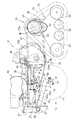
前記構成の前輪17の支持構造にあっては、図1に示すように、車軸52の軸芯cが左右方向に一致するように配置された状態において(前輪17が左右軸回りに回転する状態において)、前輪支軸24の軸芯aと車軸52の軸芯c(前輪17の回転軸芯)とに直交する線eに対して回動軸芯cが直交するように構成されている。
And when the volt |
The
In the support structure for the
そして、図1(a)に示すように、可動筒59が回動支軸50の下部側に位置する状態から、前輪支持アーム19の取付部22を前輪支軸24のアーム取付部25から取り外して反転させ、この反転させた状態で前輪支持アーム19の取付部22を前輪支軸24のアーム取付部25に取り付けると、図1(b)に示すように、可動筒59が回動支軸50の上部側に位置する状態となる。
この反転前と反転後において、回動支軸50の軸芯dは前後方向の線fに対して同じ角度gとされている。
Then, as shown in FIG. 1A, the mounting
Before and after the reversal, the axis d of the
また、反転前と反転後において、前輪支軸24の軸芯aと回動支軸50の軸芯cとの前後方向に関する距離L1及び上下方向に関する距離L2は共に同じ寸法とされており、前輪17は、反転前と反転後において、同じ高さ位置で、前後方向の線fに対して同じ角度gの回動軸芯d回りにトー角の調整を行うことができ、反転前と反転後とにおいて、前輪17のトー角の調整を同じように行うことができるようになっている。
図8は、前輪支持アーム19を左右反転させて取り付けた場合に、反転前と反転後で、トー角の調整が同じように行えない比較例を示している。
Before and after inversion, the distance L1 in the front-rear direction and the distance L2 in the up-down direction between the axis a of the front
FIG. 8 shows a comparative example in which the toe angle cannot be adjusted in the same manner before and after the inversion when the front
図8において、(a)は前輪支持アーム19の反転前又は反転後の一方を示しており、(b)は前輪支持アーム19の反転前又は反転後の他方を示している。
この比較例のものは、車軸52の軸芯cが左右方向に一致するように配置された状態において、前輪支軸24の軸芯aと車軸52の軸芯cとに直交する線eが回動支軸50の軸芯dと直交していなく、反転前と反転後とで、前輪17のトー角の調整が同じように行えない。
なお、本発明は前記実施形態のものに限定されることはなく、クローラ式走行装置20の代わりに後輪を採用したものであってもよく、また、後輪を車輪支持アームの下端側にトー角調整可能に支持すると共に該車輪支持アームを反転させることにより後輪のトレッド変更を可能としたものに本発明を採用してもよい。
8A shows one of the front
In this comparative example, a line e perpendicular to the axis a of the front
The present invention is not limited to that of the above-described embodiment, and a rear wheel may be adopted instead of the crawler
本発明を採用する移植機は乗用型であってもよく、また、その他の作業機に本発明を採用してもよい。 The transplanter that employs the present invention may be a riding type, and the present invention may be employed in other working machines.
13 走行機体
17 車輪(前輪)
19 車輪支持アーム(前輪支持アーム)
22 取付部
24 車輪支軸(前輪支軸)
49 アーム本体
50 回動支軸
51 トー角調整機構
52 車軸
58 固定プレート
59 可動筒
60 可動プレート
61 固定手段
a 前輪支軸の軸芯
d 回動軸芯(回動支軸の軸芯)
e 車輪支軸の軸芯と車輪の回転軸芯とに直交する線
f 前後方向の線
g 角度
13 traveling
19 Wheel support arm (front wheel support arm)
22 Mounting
49
e Line perpendicular to the axis of the wheel spindle and the axis of rotation of the wheel f Line in the front-rear direction g Angle
Claims (3)
車輪支持アーム(19)の取付部(22)を左右反転させて走行機体(13)に取り付けたときに、反転前と反転後とにおいて、車輪(17)が同じ高さ位置で、車輪(17)の回転軸芯(c)を通る前後方向の線(f)に対して同じ角度(g)の回動軸芯(d)回りにトー角の調整が可能となるように構成されていることを特徴とする走行体。 A wheel support arm (19) provided with wheels (17) on both left and right sides of the traveling machine body (13), and each of the left and right wheels (17) provided with an attachment portion (22) attached to the traveling machine body (13) on one end side. In the traveling body which is rotatably supported on the other end side of the vehicle, the tread of the wheel (17) can be changed by attaching the mounting portion (22) to the traveling body (13) by reversing the left and right.
When the attachment part (22) of the wheel support arm (19) is reversed left and right and attached to the traveling machine body (13), the wheel (17) is at the same height position before and after inversion, and the wheel (17 The toe angle can be adjusted around the rotation axis (d) at the same angle (g) with respect to the longitudinal line (f) passing through the rotation axis (c) . A traveling body characterized by.
Priority Applications (1)
| Application Number | Priority Date | Filing Date | Title |
|---|---|---|---|
| JP2008109024A JP4989546B2 (en) | 2008-04-18 | 2008-04-18 | Traveling body |
Applications Claiming Priority (1)
| Application Number | Priority Date | Filing Date | Title |
|---|---|---|---|
| JP2008109024A JP4989546B2 (en) | 2008-04-18 | 2008-04-18 | Traveling body |
Publications (2)
| Publication Number | Publication Date |
|---|---|
| JP2009254310A JP2009254310A (en) | 2009-11-05 |
| JP4989546B2 true JP4989546B2 (en) | 2012-08-01 |
Family
ID=41382568
Family Applications (1)
| Application Number | Title | Priority Date | Filing Date |
|---|---|---|---|
| JP2008109024A Active JP4989546B2 (en) | 2008-04-18 | 2008-04-18 | Traveling body |
Country Status (1)
| Country | Link |
|---|---|
| JP (1) | JP4989546B2 (en) |
Families Citing this family (4)
| Publication number | Priority date | Publication date | Assignee | Title |
|---|---|---|---|---|
| JP6319206B2 (en) * | 2015-06-29 | 2018-05-09 | 井関農機株式会社 | Work vehicle |
| CN111247057B (en) * | 2017-12-25 | 2022-08-09 | 株式会社久保田 | Working vehicle |
| JP6758277B2 (en) * | 2017-12-25 | 2020-09-23 | 株式会社クボタ | Work vehicle |
| JP6758278B2 (en) * | 2017-12-25 | 2020-09-23 | 株式会社クボタ | Work vehicle |
Family Cites Families (4)
| Publication number | Priority date | Publication date | Assignee | Title |
|---|---|---|---|---|
| JP3572468B2 (en) * | 1995-10-23 | 2004-10-06 | ヤンマー農機株式会社 | Transplant machine |
| JP3965000B2 (en) * | 1999-02-24 | 2007-08-22 | ヤンマー農機株式会社 | Traveling part of vegetable transplanter |
| JP2001213368A (en) * | 2000-02-02 | 2001-08-07 | Kubota Corp | Front wheel mounting structure for traveling body |
| JP2004081076A (en) * | 2002-08-26 | 2004-03-18 | Seirei Ind Co Ltd | Vegetable transplanter |
-
2008
- 2008-04-18 JP JP2008109024A patent/JP4989546B2/en active Active
Also Published As
| Publication number | Publication date |
|---|---|
| JP2009254310A (en) | 2009-11-05 |
Similar Documents
| Publication | Publication Date | Title |
|---|---|---|
| JP4989546B2 (en) | Traveling body | |
| JP6590151B2 (en) | Seedling transplanter | |
| JP2006298267A (en) | Mobile agricultural machine | |
| JP5378104B2 (en) | Walking type management machine | |
| JP6098627B2 (en) | Seedling transplanter | |
| JP2000300005A (en) | Rice paddy weeder | |
| JP5069169B2 (en) | Transplanter | |
| JP2016119879A5 (en) | ||
| JPH09289808A (en) | Transplanter | |
| JP4484755B2 (en) | Rotating body for scraping of rice transplanter | |
| JP3520196B2 (en) | Vehicle wheel adjuster | |
| JP6483011B2 (en) | Work vehicle | |
| JP6304414B2 (en) | Seedling transplanter | |
| JP2943370B2 (en) | Seedling machine | |
| JP5103261B2 (en) | Transplanter | |
| JP2009262720A (en) | Transplanter | |
| JP2006321393A (en) | Mobile agricultural machine | |
| JP2022073151A (en) | Riding-type seedling transplanting machine | |
| JP2010075087A (en) | Travel device of seedling transplanter | |
| JP2008220193A (en) | Paddy field working machine | |
| JP2006101753A (en) | Revolving stand | |
| JPS637553Y2 (en) | ||
| JP5135260B2 (en) | Planting machine | |
| JP2022088697A (en) | Riding-type seedling transplanter | |
| JP2023001732A (en) | Traveling vehicle body |
Legal Events
| Date | Code | Title | Description |
|---|---|---|---|
| A621 | Written request for application examination |
Free format text: JAPANESE INTERMEDIATE CODE: A621 Effective date: 20100927 |
|
| A977 | Report on retrieval |
Free format text: JAPANESE INTERMEDIATE CODE: A971007 Effective date: 20111220 |
|
| A131 | Notification of reasons for refusal |
Free format text: JAPANESE INTERMEDIATE CODE: A131 Effective date: 20120124 |
|
| A521 | Written amendment |
Free format text: JAPANESE INTERMEDIATE CODE: A523 Effective date: 20120321 |
|
| TRDD | Decision of grant or rejection written | ||
| A01 | Written decision to grant a patent or to grant a registration (utility model) |
Free format text: JAPANESE INTERMEDIATE CODE: A01 Effective date: 20120417 |
|
| A01 | Written decision to grant a patent or to grant a registration (utility model) |
Free format text: JAPANESE INTERMEDIATE CODE: A01 |
|
| A61 | First payment of annual fees (during grant procedure) |
Free format text: JAPANESE INTERMEDIATE CODE: A61 Effective date: 20120427 |
|
| R150 | Certificate of patent or registration of utility model |
Free format text: JAPANESE INTERMEDIATE CODE: R150 Ref document number: 4989546 Country of ref document: JP Free format text: JAPANESE INTERMEDIATE CODE: R150 |
|
| FPAY | Renewal fee payment (event date is renewal date of database) |
Free format text: PAYMENT UNTIL: 20150511 Year of fee payment: 3 |