JP4987397B2 - Simulated fuel rod for nuclear reactor - Google Patents
Simulated fuel rod for nuclear reactor Download PDFInfo
- Publication number
- JP4987397B2 JP4987397B2 JP2006241578A JP2006241578A JP4987397B2 JP 4987397 B2 JP4987397 B2 JP 4987397B2 JP 2006241578 A JP2006241578 A JP 2006241578A JP 2006241578 A JP2006241578 A JP 2006241578A JP 4987397 B2 JP4987397 B2 JP 4987397B2
- Authority
- JP
- Japan
- Prior art keywords
- cladding tube
- thermocouple
- fuel rod
- nuclear reactor
- mounting groove
- Prior art date
- Legal status (The legal status is an assumption and is not a legal conclusion. Google has not performed a legal analysis and makes no representation as to the accuracy of the status listed.)
- Expired - Fee Related
Links
Images


Classifications
-
- Y—GENERAL TAGGING OF NEW TECHNOLOGICAL DEVELOPMENTS; GENERAL TAGGING OF CROSS-SECTIONAL TECHNOLOGIES SPANNING OVER SEVERAL SECTIONS OF THE IPC; TECHNICAL SUBJECTS COVERED BY FORMER USPC CROSS-REFERENCE ART COLLECTIONS [XRACs] AND DIGESTS
- Y02—TECHNOLOGIES OR APPLICATIONS FOR MITIGATION OR ADAPTATION AGAINST CLIMATE CHANGE
- Y02E—REDUCTION OF GREENHOUSE GAS [GHG] EMISSIONS, RELATED TO ENERGY GENERATION, TRANSMISSION OR DISTRIBUTION
- Y02E30/00—Energy generation of nuclear origin
- Y02E30/30—Nuclear fission reactors
Landscapes
- Monitoring And Testing Of Nuclear Reactors (AREA)
Description
本発明は、例えば沸騰水型原子炉(以下、BWRと記す)用燃料集合体の伝熱流動性能の評価試験に使用される原子炉用模擬燃料棒に関する。 The present invention relates to a simulated fuel rod for a reactor used for an evaluation test of a heat transfer flow performance of a fuel assembly for a boiling water reactor (hereinafter referred to as BWR), for example.
一般にBWR用燃料集合体では、原子力プラントの運転コスト低減を実現するため、限界出力が高く、圧力損失の小さな燃料集合体が求められている。
このような新しい燃料集合体の冷却特性を理解するために燃料集合体の伝熱流動性能を評価するための試験が行われている。
In general, a BWR fuel assembly is required to have a high limit output and a small pressure loss in order to reduce the operating cost of a nuclear power plant.
In order to understand the cooling characteristics of such a new fuel assembly, tests for evaluating the heat transfer flow performance of the fuel assembly have been conducted.
この燃料集合体の伝熱流動性能を評価するための試験では、実際の核燃料棒を使用するのではなく、実機燃料棒の表面状態を模擬して製造され、電気ヒータを備えた原子炉用模擬燃料棒(以下ヒータロッドと記す)を使用して行われている。 In the test to evaluate the heat transfer flow performance of this fuel assembly, the actual nuclear fuel rod is not used, it is manufactured by simulating the surface state of the actual fuel rod, and it is simulated for a reactor equipped with an electric heater. This is done using fuel rods (hereinafter referred to as heater rods).
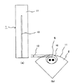
従来の代表的なヒータロッドの構成を図7に示す。
図示するように従来のヒータロッド1は、端部が閉塞された長尺、円筒状の、通常ステンレスあるいはインコネル等の金属材料によってできた被覆管2と、この被覆管2の内部に間隔を置いて同軸状に収納された内側電気絶縁材3−1および外側電気絶縁材3−2と、この内側電気絶縁材3−1と外側電気絶縁材3−2との間に配置されたニクロム線などから成る発熱体4および被覆管2の外表面に埋め込まれた熱電対5とから構成されている。
FIG. 7 shows a configuration of a conventional representative heater rod.
As shown in the figure, a
伝熱流動性能の評価試験に際しては、発熱体4に電流を流し、ヒータロッド1を発熱させる事により実機燃料棒を模擬させるようにしている。
発熱体4で発生した熱は、電気絶縁材3を伝導で伝わり、被覆管2に伝わり、さらに被覆管2内部を熱伝導で伝わり、最終的に外部の冷却流体へ熱伝達される。
In the evaluation test of the heat transfer flow performance, an actual fuel rod is simulated by passing an electric current through the
The heat generated in the
内側、外側の電気絶縁材3は例えば酸化マグネシゥム(MgO)、ボロンナイト(BN)などの絶縁材によって構成されている。
電気絶縁材3の熱伝導率、発熱体4と電気絶縁材3との接触抵抗、そして電気絶縁材3と被覆管2との接触抵抗を良好にし、発熱体4の温度を低く抑えるために、発熱体4と被覆管2との間に電気絶縁材3−2を詰めた後、被覆管2を減径するためにスエージング工程により電気絶縁材3−2の密度の増加そして密着度合いを改善している。
The inner and outer electrical
In order to improve the thermal conductivity of the electrical
伝熱流動性能を評価するための温度測定用の熱電対5は、被覆管2の外表面あるいは内表面に溝を切り、そこに埋め込まれて温度を測定している。
このように構成されたヒータロッド1は、圧力容器に収納され伝熱流動性能の評価試験が行われる。
The
The
図8は、ヒータロッド1を圧力容器6内に収納した状態を示す。通常、冷却材7が圧力容器6の下部より圧力容器6内に供給され、圧力容器6内の中央部に配置されたヒータロッド1の熱を奪い、除去した後圧力容器6の上部より排出される。
FIG. 8 shows a state where the
ヒータロッド1は、図示しない外部電源から発熱体4に電気が供給されるため、発熱体4には外部電源に接続される電極8が接続されており、圧力容器6の下部フランジ9から電極8部分が導出される。
Since the
軽水炉の試験の場合は、圧力容器6内は高圧(例えば約7MPa)で行われる事が多く、電極8の導出部の圧力シールそして電気絶縁のために電極8は被覆管2と共に下部フランジ9に気密に接続され外部へ導出される。
In the case of a light water reactor test, the inside of the pressure vessel 6 is often performed at a high pressure (for example, about 7 MPa), and the
このような従来のヒータロッド1においては以下に述べるような解決すべき課題があった。
即ち、実機核燃料棒の被覆管材料は一般にジルカロイが用いられているが、ヒータロッド1の被覆管2の材質としてはジルカロイが高価であるためステンレスあるいはインコネル等の材料が用いられている。
Such
That is, Zircaloy is generally used as the cladding material of the actual nuclear fuel rod, but since Zircaloy is expensive, a material such as stainless steel or Inconel is used as the material of the
前記したように、通常、ヒータロッド1を圧力容器6から導出する場合、圧力シールのために、ヒータロッド1を構成する被覆管2と圧力容器6の下部フランジ9とを溶接する必要があるが、下部フランジ9は通常ステンレスでできており、ヒータロッド1の被覆管2の材質をなるべく実機核燃料棒に近ずけるため核燃料棒の被覆管と同じジルカロイで構成した場合、下部フランジ9と被覆管2とは異種金属となるため両者を溶接することができない。
As described above, normally, when the
また、下部フランジ9をジルカロイで作る事も考えられるが、非常に高価であり、従来圧力容器の下部フランジをジルカロイで製作した例もない。
加えて、被覆管2の材質を圧力容器6内部で、引き出し部分をジルカロイからステンレスに変更する事も考えられるが、この場合もジルカロイとステンレスとの異種金属となり溶接ができないという課題がある。
Although it is conceivable to make the lower flange 9 with Zircaloy, it is very expensive, and there is no example in which the lower flange of a conventional pressure vessel is manufactured with Zircaloy.
In addition, it is conceivable that the material of the
一方、熱電対5は、通常被覆管2の外表面に形成した溝内に取り付けられており、熱電対5をこの溝内に取り付けることにより、取付け用の溝が被覆管2表面に露出してしまい、被覆管2の外表面の表面状態が実機核燃料棒の表面状態と異なってしまう。
On the other hand, the
これを防ぐため、熱電対5を被覆管2の内面に取り付けることによって表面状態を同じにする事が考えられているが、外面に取り付ける場合に比較して、製造が面倒であり、高価となる。
In order to prevent this, it is considered that the surface state is made the same by attaching the
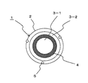
さらに、上記課題を解決するために図9に示すように、ヒータロッド1の最外周にある被覆管2を二重にして内側被覆管2−1と外側被覆管2−2としたヒータロッドが考えられている。
このようにすると、外側被覆管2−2をジルカロイで製造すれば実機燃料棒表面材質であるジルカロイと同等の材質とすることができる。
Furthermore, in order to solve the above-mentioned problem, as shown in FIG. 9, there is a heater rod in which the
If it does in this way, if the outer side cladding tube 2-2 is manufactured with a zircaloy, it can be set as the material equivalent to the zircaloy which is an actual fuel rod surface material.
また、図9に示すように内側被覆管2−1表面に取付け用の溝を形成し、この溝内に熱電対5を埋め込むことで、熱電対取り付け用の溝が外側被覆管2−2の外表面に形成されずに、ヒータロッド1の表面状態が実機核燃料棒と同じ滑らかなヒータロッドを得られるという利点があり、上記課題をクリアすることができると考えられる。
Further, as shown in FIG. 9, a groove for attachment is formed on the surface of the inner cladding tube 2-1, and the
しかし、外側被覆管2−2を内側被覆管2−1に密着させる場合両者の密着性に均一性が保たれているかどうかの検査ができず、両被覆管2−1、2−1間に不必要なギャップが形成されていた場合、熱の伝達が不均一になったり、熱の伝達が良好に行われなかったりして正確な伝熱流動性能の評価試験が行えない、という課題がある。 However, when the outer cladding tube 2-2 is in close contact with the inner cladding tube 2-1, it is impossible to inspect whether the adhesion between the two cladding tubes 2-1 is maintained. When an unnecessary gap is formed, there is a problem that heat transfer becomes uneven or heat transfer is not performed properly, so that an accurate evaluation test of heat transfer flow performance cannot be performed. .
本発明は以上の課題を解決するためになされたものであり、被覆管表面状態をより一層実機核燃料棒の外表面の状態に近づけ、より正確な伝熱流動性能の評価試験が行える原子炉用模擬燃料棒を得ることを目的とする。 The present invention has been made in order to solve the above-described problems. For the nuclear reactor, the cladding surface state can be made closer to the state of the outer surface of the actual nuclear fuel rod, and a more accurate heat transfer flow performance evaluation test can be performed. The purpose is to obtain a simulated fuel rod.
以上の目的を達成するために、本発明に係る原子炉用模擬燃料棒は、原子炉の実機核燃料棒の表面状態を模擬して製造される原子炉用模擬燃料棒であって、ステンレス又はインコネルからなる被覆管と、この被覆管内に絶縁体を介して収納された発熱体と、前記被覆管の外表面の長手方向に形成された熱電対取り付け溝と、この熱電対取り付け溝に埋め込まれた熱電対と、前記被覆管の外表面に溶射されて設けられ前記熱電対を覆う溶射層と、を有し、前記溶射層はジルカロイにより形成されたことを特徴とする。 In order to achieve the above object, a simulated fuel rod for a reactor according to the present invention is a simulated fuel rod for a reactor manufactured by simulating the surface state of an actual nuclear fuel rod of a nuclear reactor, and is made of stainless steel or Inconel. And a heating element housed in the cladding tube via an insulator, a thermocouple mounting groove formed in the longitudinal direction of the outer surface of the cladding tube, and embedded in the thermocouple mounting groove possess a thermocouple, and a sprayed layer covering the thermocouple provided is sprayed on the outer surface of the cladding tube, wherein the thermal sprayed layer is characterized in that it is formed by zircaloy.
本発明によれば、被覆管表面状態をより一層実核燃料棒の害表面の状態に近づけ、より正確な伝熱流動性能の評価試験が行える原子炉用模擬燃料棒を得ることができる。 According to the present invention, it is possible to obtain a simulated fuel rod for a nuclear reactor in which the surface state of the cladding tube is made closer to the state of the harmful surface of the actual nuclear fuel rod and the heat transfer flow performance evaluation test can be performed more accurately.
以下、本発明の実施の形態について図面を参照して説明する。
(第1の実施の形態)
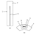
まず、図1を参照して本発明の第1の実施の形態について説明する。
なお、以下の実施の形態の説明において、図7乃至図9に示す従来のものと同一部分には同一の符号を付し、詳細な説明は省略する。
Hereinafter, embodiments of the present invention will be described with reference to the drawings.
(First embodiment)
First, a first embodiment of the present invention will be described with reference to FIG.
In the following description of the embodiment, the same parts as those of the conventional one shown in FIGS. 7 to 9 are denoted by the same reference numerals, and detailed description thereof is omitted.
図1において、1は原子炉用模擬燃料棒(ヒータロッド)、2は円筒状の被覆管、3−1は内側電気絶縁材、3−2は外側電気絶縁材、4は発熱体、10は被覆管2の外表面に形成された熱電対取り付け溝、5は前記熱電対取り付け溝10中に埋め込まれた熱電対である。
In FIG. 1, 1 is a nuclear reactor simulated fuel rod (heater rod), 2 is a cylindrical cladding tube, 3-1 is an inner electrical insulator, 3-2 is an outer electrical insulator, 4 is a heating element,
11は被覆管2の外表面全体に亘って被覆管2と同じ材質の粒子を溶射によって被覆した溶射層である。
ここで、溶射とは、コーティング材料を、加熱により溶融もしくは軟化させ(「溶」)、微粒子状にして加速し被覆対象物表面に衝突させて(「射」)、扁平に潰れた粒子を凝固・堆積させることにより被覆対象物表面に皮膜を形成するコーティング技術の一種であり、るものである。
Here, thermal spraying means that the coating material is melted or softened by heating (“melting”), accelerated into fine particles and collided with the surface of the object to be coated (“spraying”), and the flattened particles are solidified. -It is a kind of coating technology that forms a film on the surface of the object to be coated by deposition.
このような構成にすると、溶射層11と被覆管2とは金属的に接着しているため、図9で説明したように従来のヒータロッドの如く外側、内側被覆管との間に隙間が生じる恐れもなくなり、熱の流れが均一となり、正確な伝熱流動性能の評価試験が行える。
With such a configuration, since the sprayed
さらに、図1に示すように被覆管2の表面に埋め込まれた熱電対5は、溶射層11により覆われるため、熱電対取り付け溝10が被覆管2の表面に露出せず、表面状態が滑らかな実核燃料棒と同じ表面状態のヒータロッドが得られ、正確な伝熱流動性能の評価試験が行える。
Furthermore, as shown in FIG. 1, since the
(第2の実施の形態)
次に本発明の第2の実施の形態について図2(a)、(b)を参照して説明する。
前記第1の実施の形態においては、被覆層2の外表面全体に亘って溶射層11を形成するようにしているが、本実施の形態においては図2に示すように溶射層11は熱電対取り付け溝10部分の外表面のみに形成するようにしている。
(Second Embodiment)
Next, a second embodiment of the present invention will be described with reference to FIGS. 2 (a) and 2 (b).
In the first embodiment, the sprayed
このような構成にすると、ヒータロッド1の被覆管2全表面に溶射層を施工するのに比べて溶射に要する施工時間が短くなり、工程の短縮ならびに材料費の低減からコストの削減が図られ、ヒータロッドの価格を低く抑えることができる。
With such a configuration, the construction time required for thermal spraying is shortened compared to the construction of the thermal spray layer on the entire surface of the
この場合溶射層部分だけが被覆管2の表面より飛び出した形となると実核燃料棒の表面状態と異なる状態となる恐れがあるため、熱電対取り付け溝10の深さを熱電対5の寸法より若干深くするか、あるいは逆に熱電対5の寸法を熱電対取り付け溝10の深さより細くすることによって熱電対取り付け用溝10内において、熱電対5の表面と被覆管2の表面との間に0.1〜0.2mm程度の隙間12を形成するようにする。
In this case, if only the sprayed layer portion protrudes from the surface of the
このような構成にすることによってその隙間12部分に溶射層11を形成するようにすれば、溶射層11表面と被覆管2表面とが面一となり、溶射層11部分が被覆管2の表面より飛び出した形となるのを防ぐことができ、正確な伝熱流動性能の評価試験が行える。
If the
(第3の実施の形態)
次に本発明の第3の実施の形態について図3(a)、(b)を参照して説明する。
本実施の形態においては、ヒータロッド1の被覆管2表面に取り付けた熱電対5の測温点13付近のみに溶射層11を形成している。
このように、被覆管2表面には熱電対5と熱電対取り付け溝10との間に空間があり、その空間が伝熱性能に影響する可能性がある。
(Third embodiment)
Next, a third embodiment of the present invention will be described with reference to FIGS. 3 (a) and 3 (b).
In the present embodiment, the sprayed
Thus, there is a space between the
本実施の形態では、伝熱性能を計測するのに重要な熱電対の測温点13付近のみ、熱電対取り付け溝10を溶射によって埋めることにより熱電対取り付け溝10がこの部分で被覆管2の表面に露出されず、ヒータロッド1の表面状態が実機核燃料棒と同じ表面状態とすることができ、正確な伝熱流動性能の評価試験が行える。
また、溶射の施工時間短縮と、材料費の低減からヒータロッドの価格をさらに低減することができる。
In the present embodiment, the
In addition, the price of the heater rod can be further reduced because of shortening the thermal spraying construction time and reducing the material cost.
(第4の実施の形態)
次に本発明の第4の実施の形態について説明する。
本実施の形態においては、図1から図3における溶射材をジルカロイとする。このようにすると、実機燃料棒表面材質はジルカロイのため、表面状態が同じ状態、同じ材質のより模擬されたヒータロッドが得られ、より正確な伝熱流動性能の評価試験が行える。
(Fourth embodiment)
Next, a fourth embodiment of the present invention will be described.
In the present embodiment, the thermal spray material in FIGS. 1 to 3 is Zircaloy. In this way, since the actual fuel rod surface material is Zircaloy, a simulated heater rod having the same surface state and the same material can be obtained, and a more accurate heat transfer flow performance evaluation test can be performed.
(第5の実施の形態)
次に本発明の第5の実施の形態について図4(a)、(b)を参照して説明する。
本実施の形態においては、熱電対5と被覆管2に形成された熱電対取り付け溝10との間の隙間12に伝熱セメント等の熱伝導率が良く、埋め込み時は柔らかく、乾燥すると硬くなる埋め込み部材14を埋め込むことにより、熱電対取り付け溝10と熱電対5との接触面の凹凸を無くし、熱伝達が良好になり、表面状態が実機核燃料棒に近いヒータロッドが得られる。
(Fifth embodiment)
Next, a fifth embodiment of the present invention will be described with reference to FIGS. 4 (a) and 4 (b).
In the present embodiment, the
埋め込み部材として用いられる伝熱セメント14は溶射材に比べて安価であるため、よりコスト削減を図ったヒータロッドが得られる。
Since the
(第6の実施の形態)
次に本発明の第6の実施の形態について図5(a)、(b)を参照して説明する。
本実施の形態においては、被覆管2に形成した熱電対取り付け溝10の大きさを可能な限り大きくし、熱電対5との隙間を大きくする。
(Sixth embodiment)
Next, a sixth embodiment of the present invention will be described with reference to FIGS. 5 (a) and 5 (b).
In the present embodiment, the size of the
これにより、伝熱セメント等の埋め込み部材14の埋め込み作業を容易にし、熱電対5と熱電対取り付け溝10との間の隙間12を埋め込み部材14により完全に満たすことができる。
これによって、熱電対5と熱電対取り付け溝10との間に隙間が無くなり、熱伝達の良いヒータロッドが得られる。
Thereby, the embedding work of the embedding
As a result, there is no gap between the
(第7の実施の形態)
次に本発明の第7の実施の形態について図6(a)、(b)を参照して説明する。
本実施の形態においては、熱電対5と熱電対取り付け溝10との間の隙間12に伝熱セメント等の埋め込み部材14を埋め込み、さらに被覆管2から露出した埋め込み部材14の外表面に溶射層11を形成することにより、よりヒータロッド1の外表面状態が実機核燃料棒と同じヒータロッドが得られる。
(Seventh embodiment)
Next, a seventh embodiment of the present invention will be described with reference to FIGS. 6 (a) and 6 (b).
In the present embodiment, an embedded
(第8の実施の形態)
次に本発明の第8の実施の形態について説明する。
本実施の形態においては、前記第1から7の実施の形態で説明したヒータロッド1の溶射層11あるいは埋め込み部材14等を埋め込んだ表面を、実機核燃料棒表面と同じ粗さに機械加工などにより研磨する。
これにより、親水性に影響がある表面粗さを実機核燃料棒と同じとしたヒータロッドが得られる。
(Eighth embodiment)
Next, an eighth embodiment of the present invention will be described.
In the present embodiment, the surface embedded with the
Thereby, a heater rod having the same surface roughness that affects hydrophilicity as that of the actual nuclear fuel rod can be obtained.
以上、本発明の好適な実施の形態について説明してきたが、本発明は上述の各実施の形態に限定されるものではなく、発明の主旨を逸脱しない範囲で種々の変形を採ることができる。例えば、上述の第1ないし第7の実施の形態に説明した特徴を任意に組み合わせたところの原子炉用模擬燃料棒の構成であっても良い。 The preferred embodiments of the present invention have been described above. However, the present invention is not limited to the above-described embodiments, and various modifications can be made without departing from the spirit of the invention. For example, the structure of the simulated fuel rod for a reactor in which the features described in the first to seventh embodiments are arbitrarily combined may be used.
1…ヒータロッド、2…被覆管、3…電気絶縁材、3−1…内側電気絶縁材、3−2…外側電気絶縁材、4…発熱体、5…熱電対、6…圧力容器、7…冷却材、8…電極、9…下部フランジ、10…熱電対取り付け溝、11…溶射層、12…隙間、13…熱電対の測温点、14…埋め込み部材。
DESCRIPTION OF
Claims (8)
ステンレス又はインコネルからなる被覆管と、この被覆管内に絶縁体を介して収納された発熱体と、前記被覆管の外表面の長手方向に形成された熱電対取り付け溝と、この熱電対取り付け溝に埋め込まれた熱電対と、前記被覆管の外表面に溶射されて設けられ前記熱電対を覆う溶射層と、を有し、前記溶射層はジルカロイにより形成されたことを特徴とする原子炉用模擬燃料棒。 A simulated fuel rod for a nuclear reactor manufactured by simulating the surface state of an actual nuclear fuel rod of a nuclear reactor,
A cladding tube made of stainless steel or Inconel, a heating element housed in the cladding tube via an insulator, a thermocouple mounting groove formed in the longitudinal direction of the outer surface of the cladding tube, and a thermocouple mounting groove a thermocouple embedded, have a, a sprayed layer covering the thermocouple provided is sprayed on the outer surface of the cladding tube, wherein the thermal sprayed layer simulating nuclear reactor, characterized in that it is formed by zircaloy Fuel rod.
Priority Applications (1)
| Application Number | Priority Date | Filing Date | Title |
|---|---|---|---|
| JP2006241578A JP4987397B2 (en) | 2006-09-06 | 2006-09-06 | Simulated fuel rod for nuclear reactor |
Applications Claiming Priority (1)
| Application Number | Priority Date | Filing Date | Title |
|---|---|---|---|
| JP2006241578A JP4987397B2 (en) | 2006-09-06 | 2006-09-06 | Simulated fuel rod for nuclear reactor |
Publications (2)
| Publication Number | Publication Date |
|---|---|
| JP2008064548A JP2008064548A (en) | 2008-03-21 |
| JP4987397B2 true JP4987397B2 (en) | 2012-07-25 |
Family
ID=39287398
Family Applications (1)
| Application Number | Title | Priority Date | Filing Date |
|---|---|---|---|
| JP2006241578A Expired - Fee Related JP4987397B2 (en) | 2006-09-06 | 2006-09-06 | Simulated fuel rod for nuclear reactor |
Country Status (1)
| Country | Link |
|---|---|
| JP (1) | JP4987397B2 (en) |
Families Citing this family (10)
| Publication number | Priority date | Publication date | Assignee | Title |
|---|---|---|---|---|
| JP5025626B2 (en) * | 2008-12-12 | 2012-09-12 | 株式会社東芝 | Simulated fuel rod, simulated fuel rod assembly, and method of manufacturing simulated fuel rod |
| KR101292190B1 (en) * | 2011-10-13 | 2013-08-02 | 한국원자력연구원 | The Sealing and Leak Test Method of an Irradiation Test Fuel Equipped with High Temperature Thermocouple |
| KR101358927B1 (en) | 2012-06-21 | 2014-02-06 | 한국원자력연구원 | Irradiation capsule for an improved temperature control by using a liquid and solid thermal media |
| CN104064226B (en) * | 2014-07-04 | 2016-08-17 | 中国科学院合肥物质科学研究院 | A kind of simulated fuel assembly subchannel heating rod spacing adjusting device |
| FR3053515B1 (en) * | 2016-06-29 | 2018-08-17 | Areva Np | NUCLEAR REACTOR, METHODS FOR MOUNTING AND REPLACING THERMOCOUPLES CONDUITS, ASSEMBLY FOR IMPLEMENTING METHODS |
| CN106710647B (en) * | 2017-01-09 | 2018-02-06 | 中国核动力研究设计院 | Cluster subchannel wall temperature analogue measurement device and method is heated under moving condition |
| JP6845063B2 (en) * | 2017-03-28 | 2021-03-17 | 一般財団法人電力中央研究所 | Control tube evaluation system |
| CN111681789A (en) * | 2020-06-22 | 2020-09-18 | 中国核动力研究设计院 | Thermal hydraulic experimental device for closely-arranged rod bundle fuel assemblies |
| CN114566299A (en) * | 2022-01-17 | 2022-05-31 | 华北电力大学 | Experimental device for simulating reaction of zirconium water in nuclear fuel element cladding of pressurized water reactor |
| CN120340915B (en) * | 2025-06-18 | 2025-09-02 | 深圳大学 | Nuclear fuel behavior reactor external simulation experiment device under reactive introduction accident |
Family Cites Families (10)
| Publication number | Priority date | Publication date | Assignee | Title |
|---|---|---|---|---|
| JPS5816457B2 (en) * | 1977-12-14 | 1983-03-31 | 助川電気工業株式会社 | Method for manufacturing simulated fuel rods |
| JPS5923430B2 (en) * | 1979-03-20 | 1984-06-01 | 助川電気工業株式会社 | How to install a thermocouple on a rod-shaped sheathed heater |
| JPS55112536A (en) * | 1980-01-24 | 1980-08-30 | Yamari Sangyo Kk | Mounting method of thermocouple onto tube wall |
| JPS59155731A (en) * | 1983-02-25 | 1984-09-04 | Mitsubishi Heavy Ind Ltd | Method for mounting temperature measuring body |
| JPS59183698U (en) * | 1983-05-25 | 1984-12-06 | 富士電機株式会社 | Thermocouple mounting structure of nuclear reactor simulated fuel rod |
| JPS60244825A (en) * | 1984-05-21 | 1985-12-04 | Okazaki Seisakusho:Kk | Temperature measuring sensor |
| JPH0531538Y2 (en) * | 1987-01-28 | 1993-08-13 | ||
| JPH055796A (en) * | 1991-06-28 | 1993-01-14 | Toshiba Corp | Mock fuel rod |
| JP2929874B2 (en) * | 1992-12-15 | 1999-08-03 | 株式会社日立製作所 | Fuel cladding tube test equipment |
| JP2701119B2 (en) * | 1993-03-29 | 1998-01-21 | 原子燃料工業株式会社 | Thermocouple cable mounting device for temperature measurement of simulated fuel rod |
-
2006
- 2006-09-06 JP JP2006241578A patent/JP4987397B2/en not_active Expired - Fee Related
Also Published As
| Publication number | Publication date |
|---|---|
| JP2008064548A (en) | 2008-03-21 |
Similar Documents
| Publication | Publication Date | Title |
|---|---|---|
| JP4987397B2 (en) | Simulated fuel rod for nuclear reactor | |
| JP3492135B2 (en) | Heat flux meter | |
| US8092086B2 (en) | Temperature sensor | |
| US3898431A (en) | Tubular electric heater with a thermocouple assembly | |
| JP7154215B2 (en) | Method for manufacturing sensor housing of force or pressure sensor and use of sensor housing, force or pressure sensor and additive manufacturing equipment | |
| JP6408693B2 (en) | heater | |
| JPS5853759B2 (en) | Local power measurement device within the reactor fuel assembly | |
| JP2009115478A (en) | Fast response thermocouple for high speed fluid | |
| KR20120040631A (en) | Thermo-couple for temperature measurement and method of manufacturing the same | |
| CN108917962B (en) | A kind of thin stick narrow gap wall temperature temperature measuring equipment under moving condition | |
| JP2010175416A (en) | Corrosion potential sensor | |
| US9046611B2 (en) | Self-powered gamma detector | |
| CN108204863A (en) | High-temperature exhaust air sensor | |
| JPS6161360B2 (en) | ||
| JPH11148909A (en) | Electrochemical corrosion potential sensor | |
| CN113252548B (en) | Electrode system of electrochemical test system for molten salt corrosion experiment | |
| CN110186581A (en) | A kind of aircraft surface temperature sensor and sensor probe | |
| JPH11142363A (en) | Electrochemical corrosion potential sensor | |
| CN110173715A (en) | Assembly method of boiler water cooling equipment and temperature measuring components | |
| CN201653574U (en) | Knife-edge type thermocouple for furnace tube of heating furnace | |
| JP4398823B2 (en) | Capsule type strain gauge installation method | |
| JP2018136263A (en) | Temperature measuring device | |
| JP2001021512A (en) | Thermal conductivity measuring device | |
| KR20240003148A (en) | CRUD simulation experiment facility and method of the same | |
| KR101326094B1 (en) | Pressure measuring apparatus having heater and method for manufacturing of the same |
Legal Events
| Date | Code | Title | Description |
|---|---|---|---|
| A621 | Written request for application examination |
Free format text: JAPANESE INTERMEDIATE CODE: A621 Effective date: 20081222 |
|
| A977 | Report on retrieval |
Free format text: JAPANESE INTERMEDIATE CODE: A971007 Effective date: 20101109 |
|
| A131 | Notification of reasons for refusal |
Free format text: JAPANESE INTERMEDIATE CODE: A131 Effective date: 20111004 |
|
| A521 | Written amendment |
Free format text: JAPANESE INTERMEDIATE CODE: A523 Effective date: 20111202 |
|
| TRDD | Decision of grant or rejection written | ||
| A01 | Written decision to grant a patent or to grant a registration (utility model) |
Free format text: JAPANESE INTERMEDIATE CODE: A01 Effective date: 20120403 |
|
| A01 | Written decision to grant a patent or to grant a registration (utility model) |
Free format text: JAPANESE INTERMEDIATE CODE: A01 |
|
| A61 | First payment of annual fees (during grant procedure) |
Free format text: JAPANESE INTERMEDIATE CODE: A61 Effective date: 20120425 |
|
| FPAY | Renewal fee payment (event date is renewal date of database) |
Free format text: PAYMENT UNTIL: 20150511 Year of fee payment: 3 |
|
| LAPS | Cancellation because of no payment of annual fees |