JP4986718B2 - Image forming apparatus and image processing method - Google Patents
Image forming apparatus and image processing method Download PDFInfo
- Publication number
- JP4986718B2 JP4986718B2 JP2007150412A JP2007150412A JP4986718B2 JP 4986718 B2 JP4986718 B2 JP 4986718B2 JP 2007150412 A JP2007150412 A JP 2007150412A JP 2007150412 A JP2007150412 A JP 2007150412A JP 4986718 B2 JP4986718 B2 JP 4986718B2
- Authority
- JP
- Japan
- Prior art keywords
- image
- reading
- image signal
- unit
- output
- Prior art date
- Legal status (The legal status is an assumption and is not a legal conclusion. Google has not performed a legal analysis and makes no representation as to the accuracy of the status listed.)
- Expired - Fee Related
Links
Images


Description
本発明は、原稿画像を読み取る原稿読取装置を備えた画像形成装置及び画像処理方法に関する。 The present invention relates to an image forming apparatus and an image processing method including a document reading device that reads a document image.
画像形成装置は、原稿画像を読取るスキャナ部、コントローラとしての画像処理部および画像を形成するプリンタ部を有する複合プリンタが主流である。スキャナ部は、基本的に印刷物、写真等の原稿上の画像をイメージセンサで光学的に読み取り画像データにする。画像処理部は、スキャナ部によって読み取られた画像データや、PC、デジタルカメラ等から供給された画像データに所定の画像処理を施し、プリンタ部で画像記録するための露光部での露光条件となる画像データを生成する。プリンタ部は、画像処理部から出力された画像データに応じて、露光部での例えば光ビーム走査によって感光材料を走査・露光して潜像を記録し、露光された感光材料に現像処理を施し、記録材上に転写する。 The mainstream of image forming apparatuses is a composite printer having a scanner unit for reading a document image, an image processing unit as a controller, and a printer unit for forming an image. The scanner unit basically optically reads an image on an original such as a printed matter or a photograph with an image sensor and generates image data. The image processing unit performs predetermined image processing on the image data read by the scanner unit and image data supplied from a PC, a digital camera, and the like, and serves as an exposure condition in the exposure unit for recording an image in the printer unit. Generate image data. In accordance with the image data output from the image processing unit, the printer unit scans and exposes the photosensitive material by, for example, light beam scanning in the exposure unit, records a latent image, and performs development processing on the exposed photosensitive material. And transferred onto a recording material.
ところで、複合プリンタのスキャナ部は、原稿に読取光を入射し、原稿で反射された反射光を、CCDセンサ等のイメージセンサで読み取ることにより、原稿画像を光学的に読み取る。また、カラー原稿の場合、スキャナ部は、原稿の反射光を赤(R)、緑(G)および青(B)の色フィルタで処理することにより、原稿画像をR、GおよびBの3原色に分解して読み取る。 By the way, the scanner unit of the composite printer optically reads an original image by making the reading light incident on the original and reading the reflected light reflected by the original with an image sensor such as a CCD sensor. In the case of a color document, the scanner unit processes the reflected light of the document with red (R), green (G), and blue (B) color filters, thereby converting the document image into the three primary colors R, G, and B. Disassemble and read.
ここで、スキャナ部では、スキャナ読み取り範囲内であれば、読み取り位置が変わっても、同じ原稿を読み取った際には、同じ画像信号(画像データ)が得られなければならない。しかしながら、スキャナに取り付けられる光源、光学系、色フィルタ、イメージセンサ等には、ムラ(例えば、個体差、感度のバラツキ、経時劣化など)があり、必ずしも全位置で原稿に応じた適正な濃度再現が得られないという問題があった。これを解決するために、予め用意されている基準原稿を読み取って画像信号を補正する画像形成装置が知られている(特許文献1、2参照)。
しかしながら、上記従来の画像形成装置では、基準原稿(基準サンプル)を使う場合、読み取り装置の特性が変化する(経時劣化、経時変化など)ようなときには、再度基準サンプルを必要とした。従って、基準サンプルの入手や保管等も煩わしく、生産性が低下する問題があった。 However, in the above-described conventional image forming apparatus, when the reference document (reference sample) is used, the reference sample is required again when the characteristics of the reading device change (deterioration with time, change with time, etc.). Therefore, it is troublesome to obtain and store the reference sample, and there is a problem that productivity is lowered.
そこで、本発明は、予め基準サンプルを用意することなく読み取りムラを補正することができる画像形成装置及び画像処理方法を提供することを目的とする。 SUMMARY An advantage of some aspects of the invention is that it provides an image forming apparatus and an image processing method capable of correcting reading unevenness without preparing a reference sample in advance.
上記目的を達成するために、本発明の画像形成装置は、原稿画像を読み取る原稿読取部を備え、前記原稿読取部により読み取られた原稿画像の画像信号に基づき、転写材に画像を形成する画像形成装置であって、前記転写材に出力画像を形成する出力画像形成手段と、前記転写材に形成された出力画像を読み取る出力画像読取手段と、前記出力画像読取手段によって読み取られた出力画像の、画像信号値およびその位置情報を含む第1の画像情報を取得する第1の画像情報取得手段と、読み取り面に対する向きが90度異なる前記出力画像を、原稿画像として、前記原稿読取部によって読み取り、各向きの出力画像の、画像信号値およびその位置情報を含む第2の画像情報を取得する第2の画像情報取得手段と、前記第1の画像情報および前記第2の画像情報から、前記原稿読取部の画像信号値が目標とする前記出力画像読取手段の画像信号値に等しくなるように、前記原稿読取部によって読み取られる原稿画像の画像信号を補正するための画像信号補正パラメータを読み取り領域内の複数の位置のそれぞれについて算出する画像信号補正パラメータ算出手段と、前記算出された画像信号補正パラメータを用いて、前記原稿読取部によって読み取られた原稿画像の画像信号を補正する補正手段とを備えることを特徴とする。 To achieve the above object, an image forming apparatus of the present invention is provided with a document reading section for reading a document image based on the image signal of the original image read by the document reading section, an image for forming an image on a transfer material An output image forming unit that forms an output image on the transfer material; an output image reading unit that reads an output image formed on the transfer material; and an output image read by the output image reading unit. a first image information obtaining means for obtaining image signal values and the first image information including the position information, the output image orientation is different from 90 degrees with respect to the reading surface, as an original image, read by the original reading portion , the output image of each orientation, the image signal value and the second image information acquisition means for acquiring second image information including the position information, the first image information and before From the second image data, wherein as the image signal values of the original reading unit is equal to the image signal value of the output image reading means as a target, for correcting an image signal of an original image read by the original reading portion and an image signal correction parameter calculating means for calculating for each of a plurality of positions of the image signal read-area correction parameters by using the image signal correction parameters the calculated, the original image read by the original reading portion And correction means for correcting the image signal .
本発明の画像形成装置の画像処理方法は、原稿画像を読み取る原稿読取部と、転写材に出力画像を形成する出力画像形成部と、前記転写材に形成された出力画像を読み取る出力画像読取部と、画像信号補正パラメータを用いて、前記原稿読取部によって読み取られた原稿画像の画像信号を補正する補正部とを有する画像形成装置のための画像処理方法であって、前記出力画像読取部によって読み取られた出力画像の、画像信号値およびその位置情報を含む第1の画像情報を取得し、読み取り面に対する向きが90度異なる前記出力画像を、原稿画像として、前記原稿読取部によって読み取り、各向きの出力画像の、画像信号値およびその位置情報を含む第2の画像情報を取得し、前記第1の画像情報および前記第2の画像情報から、前記原稿読取部の画像信号値が目標とする前記出力画像読取部の画像信号値に等しくなるように、前記原稿読取部によって読み取られる原稿画像の画像信号を補正するための前記画像信号補正パラメータを読み取り領域内の複数の位置のそれぞれについて算出することを特徴とする。 An image processing method of an image forming apparatus according to the present invention includes a document reading unit that reads a document image, an output image forming unit that forms an output image on a transfer material, and an output image reading unit that reads an output image formed on the transfer material. When, by using the image signal correction parameter, an image processing method for an image forming apparatus and a correcting section that corrects the image signal of an original image read by said original reading unit, by the output image reading unit of the read output image, the image signal values and obtains the first image information including the position information, the output image orientation with respect to the reading surface is different by 90 degrees, as an original image, read by the document reading unit, the the direction of the output image from the image signal values and obtains the second image information including the position information, the first image information and said second image information, the document As the image signal value of the isolation portion is equal to the image signal value of the output image reading unit to the target, reading area the image signal correction parameters for correcting the image signal of the original image read by the original reading portion characterized in that you calculated for each of a plurality of positions of the inner.
本発明の請求項1に係る画像形成装置では、転写材に出力画像を形成し、出力画像読取手段で読み取られた出力画像の画像信号とその位置情報、および原稿読取装置で読み取られた出力画像の画像信号とその位置情報から、原稿読取装置の画像信号値が目標とする前記出力画像読取手段の画像信号値に等しくなるように、画像信号補正パラメータを算出する。従って、予め基準サンプルを用意することなく読み取りムラを補正することができる。 In the image forming apparatus according to the first aspect of the present invention, an output image is formed on a transfer material, the image signal of the output image read by the output image reading means and its position information, and the output image read by the document reading device. The image signal correction parameter is calculated from the image signal and its position information so that the image signal value of the document reading apparatus is equal to the target image signal value of the output image reading means . Therefore, it is possible to correct reading unevenness without preparing a reference sample in advance.
本発明の画像形成装置及び画像処理方法の実施の形態について図面を参照しながら説明する。本実施形態の画像形成装置はカラーデジタルプリンタに適用される。 Embodiments of an image forming apparatus and an image processing method of the present invention will be described with reference to the drawings. The image forming apparatus of this embodiment is applied to a color digital printer.
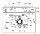
図1は実施の形態におけるカラーデジタルプリンタ1の構成を示す断面図である。カラーデジタルプリンタ1は、箱形の本体を有する。また、その本体上部には、原稿読取装置として反射原稿読み取り用のスキャナ部200が設けられている。また、本体内部には、画像処理装置14(図3参照)が設けられている。
FIG. 1 is a cross-sectional view showing a configuration of a color
スキャナ部200からの読取画像信号は、後述するように、他の画像データ供給手段(例えば、デジタルカメラ等)からの画像信号と共に、画像処理装置14に入力され、この画像処理装置14において、所定の画像処理が施される。また、本実施形態では、出力画像読取装置として、定着器109の下流側の搬送経路上には、その主走査方向中央にカラーセンサ3000が1つ設置されている。
As will be described later, the read image signal from the
プリンタ1内の感光ドラム101には、金属の導電性基材101bおよびこの上の感光体層101aが設けられている。帯電ローラ102は芯金102bを有し、この芯金102bの表層には、弾性層102aが設けられており、感光ドラム101は均一に帯電されている。バイアス電源111は、帯電ローラ102の芯金102bに電圧を印加する。
The
帯電された感光ドラム101の面上には、発振波長約700〜800nmのレーザ光(露光光)103が照射され、静電潜像が形成される。レーザ光103のON/OFF動作は、入力された画像データを処理して得られるデータに基づいて行われる。
On the surface of the charged
現像装置104は、感光ドラム101面上の静電潜像を顕像化するものであり、現像スリーブ104aには、現像バイアス電源112により現像バイアスが印加されている。転写ローラ105は、感光ドラム101面上に顕像化されたトナー像を転写材(図示せず)に転写する。芯金105bの表層には、中抵抗弾性層105aが設けられている。バイアス電源113は、転写ローラ105の芯金105bに電圧を印加する。
The developing
転写ガイド106は、転写ローラ105と感光ドラム101との間に転写材を導く。クリーナ107は、クリーニングブレード107aを有し、感光ドラム101面上に残ったトナーや紙粉等を除去する。
The
転写の終了した転写材は、搬送ガイド108によって定着器109に送られる。定着器109は、定着ローラ109aおよび加圧ローラ109bから構成される。定着器109によって転写材を加圧・加熱することにより、転写材にはトナー像が定着する。
After the transfer, the transfer material is sent to the
つぎに、スキャナ部200について詳述する。スキャナ部200は、箱型のケーシングによって覆われており、その上面中央部には、矩形の開口部が設けられ、透明のプラテンガラス202が嵌め込まれている。
Next, the
プラテンガラス202は、平面原稿載置台としての機能を有し、その上には、平面画像を記録した反射原稿が載置されるようになっている。また、プラテンガラス202には、開閉可能な押さえカバー204が設けられている。スキャナ部200には、走査部208が設けられている。走査部208は、コントローラ209によって制御される。
The
走査部208は、反射原稿用光源ユニット210、第1のキャリッジ214、第2のキャリッジ220および固定ユニット228から構成される。反射原稿用光源ユニット210は、原稿画像の幅方向(主走査方向)に延出されたハロゲンランプおよびリフレクタを備える。第1のキャリッジ214には、この反射原稿用光源ユニット210と共に原稿画像の幅方向に延出された第1のミラー212が組み込まれている。第2のキャリッジ220には、第2のミラー216および第3のミラー218が組み込まれている。固定ユニット228は、絞り222、色調整フィルタおよびNDフィルタ等で4枚構成とされるフィルタ群224、および結像のためのレンズ226から構成される。
The
第1のキャリッジ214は、反射原稿用光源ユニット210からの光をプラテンガラス202面上に載置された原稿に照射し、その反射光(垂下する光軸の光)を第1のミラー212で90°偏向し、第2のキャリッジ220の第2のミラー216へ案内する。
The
第2のキャリッジ220は、第2のミラー216の反射面が第1のミラー212の反射面と対向し、かつ平行な状態に配置されているので、第1のミラー212から光を受けると、第2のミラー216で90°偏向し、さらに第3のミラー218で90°偏向する。この第3のミラー218で最終的にプラテンガラス202の面と平行に偏向された光は、固定ユニット228を経て、ラインCCDセンサ230の受光部に至る。図2はラインCCDセンサ230の受光部34の構成を示す図である。ラインCCDセンサ230の受光部34は、各色(RGB)毎に独立して受光量を検出する3本のラインセンサ34R、34G、34Bで構成される。
The
固定ユニット228では、絞り222やフィルタ群224のNDフィルタによって光量の調整が行われ、フィルタ群224の色調整フィルタによって各色バランスの調整が行われる。また、レンズ226によって、原稿画像がラインCCDセンサ230の受光面上で結像する。なお、色調整フィルタのレンズ表面には、IRカットフィルタに相当するIRカット膜が蒸着されている。
In the fixed
第2のキャリッジ220は、プラテンガラス202の下方で原稿面に沿って副走査方向に往復移動する。このとき、原稿反射位置からラインCCDセンサ230の受光部34までの光路長を常に一定に維持するべく、第2のキャリッジ220が第1のキャリッジ214の1/2の搬送速度で同一方向へ移動するようになっている。
The
この第1のキャリッジ214および第2のキャリッジ220の1往復動作は、1画像分の走査に相当し、往路時に画像読取が行われる。これにより、プラテンガラス202上の原稿画像を読み取ることができる。
One reciprocation of the
なお、スキャナとしては、上述のようなスリット走査によるものに限定されず、1コマの画像の全面を一度に読み取る、面露光を利用するものであってもよい。この場合、例えば、エリアCCDセンサを用い、光源との間に、R,GおよびBの各色フィルタを挿入する手段を設け、色フィルタを挿入してエリアCCDセンサで画像を読み取る動作を、R,GおよびBの各色フィルタで順次行う。即ち、画像を3原色に分解して順次読み取り動作を行う。 The scanner is not limited to the one using the slit scanning as described above, and may use a surface exposure that reads the entire image of one frame at a time. In this case, for example, an area CCD sensor is used, and means for inserting R, G, and B color filters between the light sources is provided. This is sequentially performed for each color filter of G and B. That is, the image is separated into three primary colors and sequentially read.
また、スキャナ部200における反射原稿画像の読取結果は、画像処理装置14に送られる。図3は画像処理装置14の内部構成を示すブロック図である。画像処理装置14は、画像処理ユニット38およびデータ変換ユニット40から構成される。画像処理ユニット38は、前処理部42、フレームメモリ44、処理部50および条件設定部52を有する。
Further, the result of reading the reflected original image in the
図4は前処理部42の構成を示す図である。前処理部42は、A/D変換部36、データ変換部37、画像信号補正部38、Log変換部39等を有する。A/D変換部36は、入力される読取画像信号のA/D(アナログ/デジタル)変換を行う。データ変換部37は、スキャナ部200で読み取られた画像信号のダイナミックレンジの調整等のデータ変換を行う。画像信号補正部38は画像データである画像信号の輝度値を補正する。この画像信号補正部38の詳細については後述する。Log変換部39は、対数変換増幅を行う。
FIG. 4 is a diagram illustrating a configuration of the
フレームメモリ44は、R,G,Bの各フレームメモリからなる。処理部50は、後述する各種の画像処理を行う。条件設定部52は、処理部50による各種の処理条件設定を司る。
The
条件設定部52は、処理部50で施される画像処理を選択すると共に、フレームメモリ44から入力された画像データを用いて処理部50における画像処理条件を設定し、処理部50に供給する。処理部50は、従来から行われている各種の画像処理を行う。
The
なお、図3には、画像処理装置14中の画像処理関連の部位のみが示されている。画像処理装置14には、これらの他、画像処理装置14を含むカラーデジタルプリンタ1全体の制御や管理を行うCPU、カラーデジタルプリンタ1の作動等に必要な情報を記憶するメモリ等が配置されている。また、操作部(図示せず)は、このCPU等(CPUバス)を介して各部位に接続される。
FIG. 3 shows only the image processing related part in the
また、画像処理装置14には、後述する出力画像読取装置であるカラーセンサ3000による出力画像の測定結果(測定位置および測定値を含む)を記憶するとともに、この測定結果を読み出して画像信号補正部38に供給する記憶装置58が接続される。ここで、記憶装置58は、内蔵メモリや外部メモリ等のメモリやハードディスク装置でもよい。また、フロッピー(登録商標)ディスク(FD)等の磁気記録媒体、MO等の光磁気記録媒体、光ディスク(CD、CD−R)等の光記録媒体などの記憶媒体とその駆動装置との組み合わせであってもよい。ここでは、その取り扱いの容易さから記憶媒体に記憶しておき、必要に応じてその駆動装置から画像信号補正部38に読み出すようにすることが行われる。
The
図5はカラーセンサ3000の構成を示す図である。同図(A)は、カラーセンサ3000の概略的構成を示し、同図(B)はカラーセンサ3000の受光素子54aの受光部54bの構成を示す。カラーセンサ3000は、転写材2027に形成された定着後のトナーパッチ画像(出力画像)61を読み取り、RGB出力値を検出するセンサである。
FIG. 5 is a diagram showing the configuration of the
カラーセンサ3000は、白色LED等の発光素子53、RGBオンチップフィルタ付き電荷蓄積型センサ、トリガ信号に使用するフォトダイオード(PD)等の受光素子54a、およびこれらを収容するホルダから構成される。
The
カラーセンサ3000は、発光素子(白色LED)53から発せられた光を、定着後のトナーパッチ画像61が形成された転写材2027に対し、斜め45度より入射させ、0度方向への乱反射光強度を受光素子54aにより検出する。受光素子54aとして、前述したRGBオンチップフィルタ付き電荷蓄積型センサが用いられる。受光素子54aの受光部54bは、独立したR、G、B画素を有する。
The
なお、受光素子54aを構成する電荷蓄積型センサはフォトダイオードであってもよい。また、受光素子54aはRGBの3画素のセットを数セット並べて構成されてもよい。また、カラーセンサ3000は、入射角が0度、反射角が45度となるように構成されてもよい。さらに、カラーセンサ3000は、RGBの3色を個別に発光するLEDおよびフィルタ無しセンサから構成されてもよい。
The charge storage sensor constituting the light receiving element 54a may be a photodiode. The light receiving element 54a may be configured by arranging several sets of three RGB pixels. The
このような構成を有するカラーセンサ3000は、転写材上のトナーパッチ画像のRGB出力値を検出し、その検出結果を画像処理装置14に出力する。そして、この検出結果を基に、各種の画像制御が行われる。
The
上記構成を有するカラーデジタルプリンタ1の通常の動作は次の通りである。すなわち、スキャナ部200で読み取られた原稿画像の画像データに対し、画像処理装置14内の画像処理ユニット38の前処理部42において、A/D変換、Log変換、DCオフセット補正、シェーディング補正等の所定のデータ処理が施される。さらに、後述する画像処理が施される。なお、画像処理装置14は、他の画像データ供給源から供給された画像データを入力し、読み取り画像データと同様に、画像処理を施すことも可能である。
The normal operation of the color
このように処理された画像データは、データ変換ユニット40において、前述したプリンタ1のプリント作成(画像記録)に対応する画像データに変換される。画像処理ユニット38は、スキャナ部200あるいは他の画像データ供給部から供給された画像信号に対して前処理を行った後、処理部50で、暗時補正やシェーディング補正等、一定濃度の画像に対して所定の画像信号を得るための補正(濃度補正)を施す。そして、所定の画像処理が施された画像データは、プリンタ1での画像記録に対応する出力用の画像データとされ、プリンタ1に出力される。プリンタ1は、供給された画像データに応じて感光体を露光して潜像を記録し、現像、転写、定着等の所定の処理を施し、プリントとして出力する。
The image data processed in this way is converted by the
なお、処理部50で施される画像処理は、特に限定されることなく、例えば、色バランス調整、階調調整、濃度調整、彩度調整、電子変倍処理、濃度ダイナミックレンジの圧縮/伸長、シャープネス(鮮鋭化)処理などでよい。ここでは、公知の画像処理装置で行われる各種の画像処理が例示されている。また、これらの各処理は、LUT、マトリックス演算器、フィルタ、加算器等を用いた処理や、これらを適宜組み合わせて行う平均化処理や補間演算等を用いた、公知の手段で行うことが可能である。
The image processing performed by the
つぎに、カラーデジタルプリンタ1におけるスキャナ面内ムラ補正パラメータ(画像信号補正パラメータ)の取得動作を示す。なお、本実施形態では、反射原稿読取用スキャナ部を代表例として、面内ムラ補正方法を示すが、本発明は、これに限定されず、透過原稿用スキャナにも適用可能であることは言うまでもない。
Next, an operation for acquiring a scanner in-plane unevenness correction parameter (image signal correction parameter) in the color
図6はスキャナ面内ムラ補正パラメータの取得動作手順を示すフローチャートである。まず、プリンタ1は、スキャナ面内ムラ補正用の出力画像を得るための画像データを、画像処理装置14で作成し、その画像形成を行う(ステップS1)。図7はスキャナ面内ムラ補正用画像を示す図である。このスキャナ面内ムラ補正用画像(出力画像)は、主走査方向の中央位置に配置されたカラーセンサ3000が検出する位置に対応した部分に、同レベルの信号で副走査方向に画いた帯び画像である。つまり、この帯画像は、搬送方向にライン状に形成された出力画像である。なお、ステップS1の処理は出力画像形成手段に相当する。
FIG. 6 is a flowchart showing an operation procedure for acquiring scanner in-plane unevenness correction parameters. First, the
プリンタ1は、転写材に転写・定着されたスキャナ面内ムラ補正用画像を、定着器109の下流側の搬送経路上に配置されたカラーセンサ3000で検出し(ステップS2)、検出した画像信号値およびその位置情報を記憶装置58に記憶する(ステップS3)。この検出した画像信号値およびその位置情報は第1の画像情報に相当し、ステップS2、S3の処理は第1の画像情報取得手段に相当する。図8はプラテンガラス202上に置かれたスキャナ面内ムラ補正用画像の位置を示す図である。同図(A)は主走査方向と長手方向が直交するようにスキャナ面内ムラ補正用画像が置かれた状態を示し、同図(B)は主走査方向と長手方向が平行するようにスキャナ面内ムラ補正用画像が置かれた状態を示す。
The
プリンタ1は、出力されたスキャナ面内ムラ補正用画像が形成された転写材を、搬送方向の向きに揃えたまま、プラテンガラス202上に置いたこと(図8(A)参照)を、画像処理装置14内の操作部(図示せず)を介して受け取る(ステップS4)。プリンタ1は、その読み取りを行う(ステップS5)。プリンタ1は、読み取った画像信号値およびその位置情報を記憶装置58に記憶する(ステップS6)。この読み取った画像信号値およびその位置情報は第2の画像情報に相当し、ステップS5、S6の処理は第2の画像情報取得手段に相当する。
The
この後、プリンタ1は、スキャナ面内ムラ補正用画像の位置(向き)を変えて測定済みであるか否かを判別する(ステップS7)。測定済みでない場合、プリンタ1は、スキャナ面内ムラ補正用画像を90°回転させ、左先端部をプラテンガラス202の左奥に合わせて置き直したこと(図8(B)参照)を、画像処理装置14内の操作部を介して受け取り(ステップS8)、S5の処理に戻る。同様に、プリンタ1は、ステップS5でその読み取りを行い、ステップS6で読み取った画像信号値およびその位置情報を記憶装置58に記憶する。
Thereafter, the
一方、ステップS7でスキャナ面内ムラ補正用画像の位置(向き)を変えて測定済みである場合、すなわち、読み取り動作が終了した場合、プリンタ1は、記憶装置58に記憶された、これらの画像情報を読み出す(ステップS9)。プリンタ1は、これらの画像情報から画像信号補正パラメータを算出して画像信号補正部38に設定する(ステップS10)。この後、プリンタ1は本動作を終了する。なお、ステップS10の処理は画像信号補正パラメータ算出手段に相当する。
On the other hand, if the position (orientation) of the scanner in-plane unevenness correction image has been changed in step S7, that is, if the reading operation has been completed, the
ここで、画像信号補正パラメータとして、目標値I1と実測値I2の2つの値からなる1組のパラメータがスキャナ読み取り領域内の全域に亘って位置毎に設定される。 Here, as an image signal correction parameter, a set of two parameters including a target value I1 and an actual measurement value I2 is set for each position over the entire area in the scanner reading area.
目標値I1は、カラーセンサ3000で読み込んだ画像信号値であり、サンプルの画像位置と関連付けられている。実測値I2は、スキャナの2回の読み取り結果(S5参照)の画像信号値を、位置に合わせて掛け合わせることで得られる値であり、二次元のスキャナ読み取り領域内の全域の位置と関連付けられている。図9は読み取り領域内の任意の位置における実測値I2の算出を示す図である。例えば、図9に示す読み取り領域内の位置であるc点の実測値I2は、対応する主走査ライン上のb点の画像信号値I2bと副走査ライン上のa点の画像信号値I2aとの積(I2a・I2b)から得られる。
The target value I1 is an image signal value read by the
また、各位置の実測値I2と同じ出力画像検出領域に対応する目標値I1は、I1、I2の位置情報(S3、S6で得られる位置情報)から同様に得られる。これにより、画像信号補正パラメータは、スキャナ読み取り領域内の全域の位置R1〜RN(図9参照)それぞれに対し、目標値I1と実測値I2のセットで設定される。このように、読み取り領域内の同位置で読み取られる、カラーセンサの画像信号値(目標値I1)に対応するスキャナの画像信号値(実測値I2)の特性が、読み取り領域内の他の位置でも等しくなるように、画像信号補正パラメータは算出される。 The target value I1 corresponding to the same output image detection area as the actual measurement value I2 of each position is similarly obtained from the position information of I1 and I2 (position information obtained in S3 and S6). Thereby, the image signal correction parameter is set as a set of the target value I1 and the actual measurement value I2 for each of the positions R1 to RN (see FIG. 9) in the entire area in the scanner reading region. As described above, the characteristics of the image signal value (actually measured value I2) of the scanner corresponding to the image signal value (target value I1) of the color sensor that is read at the same position in the reading area can be obtained at other positions in the reading area. The image signal correction parameters are calculated so as to be equal.
図10は画像信号を変換する際の画像信号補正パラメータを示すグラフである。横軸(IN)は画像信号補正部38に入力される画像信号値を示し、縦軸(OUT)は画像信号補正部38から出力される画像信号値を示す。画像信号補正部38は、この画像信号補正パラメータを用いて、A/D変換後の画像データの輝度値(画像信号値)を補正する。ここで、補正する輝度値をXとすると、補正された輝度値Yは、数式(1)、(2)で求められる。
FIG. 10 is a graph showing image signal correction parameters when converting an image signal. The horizontal axis (IN) indicates the image signal value input to the image
X≦I2の場合
Y=(X−A)*(I1−α)/(I2−A)+α ……(1)
X>I2の場合
Y=(X−I2)*(β−I1)/(B−I2)+I1 ……(2)
ただし、α、A、β、Bは、それぞれ入力値が最小値であるときの目標値、実測値、入力値が最大値であるときの目標値、実測値である。これらの値は、工場出荷時に調整され、記憶部58に記憶されている。この画像信号補正パラメータを用い、全領域において画像信号を補正することで、面内の読み取りムラを補正することができる。
When X ≦ I2 Y = (X−A) * (I1−α) / (I2−A) + α (1)
When X> I2 Y = (X−I2) * (β−I1) / (B−I2) + I1 (2)
Here, α, A, β, and B are a target value and an actual value when the input value is the minimum value, and a target value and an actual value when the input value is the maximum value, respectively. These values are adjusted at the time of shipment from the factory and stored in the
このように、本実施形態のカラーデジタルプリンタによれば、予め基準サンプルを用意することなく読み取りムラを補正することができる。また、スキャナの読み取り領域の全域に亘って読み取りムラを無くすことができる。また、出力画像を簡単かつ少ない面積で形成することができる。また、少ない面積で形成された出力画像であっても、複数回読み取ることで、読み取り領域の全域に亘って画像信号補正パラメータを算出することができる。 As described above, according to the color digital printer of this embodiment, it is possible to correct reading unevenness without preparing a reference sample in advance. Further, uneven reading can be eliminated over the entire reading area of the scanner. Further, the output image can be formed easily and with a small area. Further, even if the output image is formed with a small area, the image signal correction parameter can be calculated over the entire reading region by reading the output image a plurality of times.
なお、本発明は、上記実施形態の構成に限られるものではなく、特許請求の範囲で示した機能、または本実施形態の構成が持つ機能が達成できる構成であればどのようなものであっても適用可能である。 The present invention is not limited to the configuration of the above-described embodiment, and any configuration can be used as long as the functions shown in the claims or the functions of the configuration of the present embodiment can be achieved. Is also applicable.
例えば、画像形成装置の本体に搭載された原稿読取装置を用いて、画像形成装置のキャリブレーションを行うものが多数知られている。このような画像形成装置の場合、本実施形態で示したような、原稿読取装置(スキャナ)の読み取りムラ補正を行った後、原稿読取装置を用いたキャリブレーションを行うことで、より精度の高いキャリブレーションが可能となる。 For example, many apparatuses that perform calibration of an image forming apparatus using a document reading device mounted on the main body of the image forming apparatus are known. In the case of such an image forming apparatus, after performing the reading unevenness correction of the document reading device (scanner) as shown in the present embodiment, the calibration using the document reading device is performed, thereby achieving higher accuracy. Calibration is possible.
また、上記実施形態では、画像信号補正パラメータは、図10に示すように、1点の目標値I1と実測値I2の組み合わせであったが、複数点の目標値と実測値の組み合わせであってもよく、濃度ムラの補正をきめ細かく行うことが可能である。 In the above embodiment, the image signal correction parameter is a combination of one target value I1 and an actual measurement value I2, as shown in FIG. 10, but is a combination of a plurality of target values and actual measurement values. In other words, the density unevenness can be finely corrected.
また、上記実施形態では、転写材に形成される出力画像は搬送方向にライン状に形成され、2回の読み取り動作が行われたが、出力画像として、スキャナの読み取り領域に相当するベタ画像であってもよい。この場合、読み取り動作を1回で済ますことができる。 Further, in the above-described embodiment, the output image formed on the transfer material is formed in a line shape in the transport direction and the reading operation is performed twice. However, the output image is a solid image corresponding to the reading area of the scanner. There may be. In this case, the reading operation can be completed only once.
また、上記実施形態では、画像形成装置として、中間転写体を使用し、この中間転写体に各色のトナー像を順次重ねて転写し、この中間転写体に担持されたトナー像を記録媒体に一括して転写する画像形成装置を例示している。しかし、この転写方式に限定されるものではなく、記録媒体担持体を使用し、この記録媒体担持体に担持された記録媒体に各色のトナー像を順次重ねて転写する画像形成装置であってもよい。 In the above-described embodiment, an intermediate transfer member is used as the image forming apparatus, and toner images of each color are sequentially transferred onto the intermediate transfer member, and the toner images carried on the intermediate transfer member are collectively transferred to a recording medium. An image forming apparatus to be transferred is illustrated. However, the present invention is not limited to this transfer method, and an image forming apparatus that uses a recording medium carrier and sequentially superimposes and transfers the toner images of each color onto the recording medium carried on the recording medium carrier. Good.
また、画像形成装置の一態様としてプリンタを例示しているが、これに限定されるものではなく、例えば複写機、ファクシミリ装置等の他の画像形成装置や、あるいはこれらの機能を組み合わせた複合機等の他の画像形成装置であってもよい。 In addition, the printer is illustrated as an aspect of the image forming apparatus, but the present invention is not limited to this. For example, the image forming apparatus may be another image forming apparatus such as a copying machine or a facsimile apparatus, or a multifunction machine combining these functions. Other image forming apparatuses may be used.
また、上記実施形態に記載されている構成部品の形状、それらの相対配置などは、本発明が適用される装置の構成や各種条件により適宜変更されるべきものであり、本発明の範囲は上記例示するもののみに限定されものではない。 In addition, the shapes of the component parts described in the above embodiment, the relative arrangement thereof, and the like should be appropriately changed according to the configuration of the apparatus to which the present invention is applied and various conditions, and the scope of the present invention is described above. It is not limited only to what is illustrated.
上記実施の形態では、複合装置の印刷方式を電子写真方式とした場合を例に挙げたが、本発明は、電子写真方式に限定されるものではなく、インクジェット方式、熱転写方式、感熱方式、静電方式、放電破壊方式など各種印刷方式に適用することができる。 In the above embodiment, the case where the printing method of the composite apparatus is an electrophotographic method has been described as an example. However, the present invention is not limited to the electrophotographic method, and an inkjet method, a thermal transfer method, a thermal method, a static method, and the like. It can be applied to various printing methods such as an electric method and a discharge destruction method.
1 カラーデジタルプリンタ
14 画像処理装置
38 画像信号補正部
42 前処理部
58 記憶装置
61 トナーパッチ画像(出力画像)
200 スキャナ
230 ラインCCDセンサ
2027 転写材
3000 カラーセンサ
DESCRIPTION OF
200
Claims (5)
前記転写材に出力画像を形成する出力画像形成手段と、
前記転写材に形成された出力画像を読み取る出力画像読取手段と、
前記出力画像読取手段によって読み取られた出力画像の、画像信号値およびその位置情報を含む第1の画像情報を取得する第1の画像情報取得手段と、
読み取り面に対する向きが90度異なる前記出力画像を、原稿画像として、前記原稿読取部によって読み取り、各向きの出力画像の、画像信号値およびその位置情報を含む第2の画像情報を取得する第2の画像情報取得手段と、
前記第1の画像情報および前記第2の画像情報から、前記原稿読取部の画像信号値が目標とする前記出力画像読取手段の画像信号値に等しくなるように、前記原稿読取部によって読み取られる原稿画像の画像信号を補正するための画像信号補正パラメータを読み取り領域内の複数の位置のそれぞれについて算出する画像信号補正パラメータ算出手段と、
前記算出された画像信号補正パラメータを用いて、前記原稿読取部によって読み取られた原稿画像の画像信号を補正する補正手段とを備えることを特徴とする画像形成装置。 Includes a document reading unit for reading a document image based on the image signal of the original image read by the document reader, an image forming apparatus for forming an image on the transfer material,
Output image forming means for forming an output image on the transfer material;
Output image reading means for reading the output image formed on the transfer material;
First image information acquisition means for acquiring first image information including an image signal value and position information of an output image read by the output image reading means;
The output image orientation is different from 90 degrees with respect to the reading surface, as an original image, read by the original reading portion, an output image of the orientation, the image signal value and the second to obtain the second image information including the position information Image information acquisition means,
From the first image information and said second image information, so that the image signal values of the original reading unit is equal to the image signal value of the output image reading means as a target document to be read by the document reading unit and an image signal correction parameter calculating means for calculating for each of a plurality of positions of the image signal read-area correction parameters for correcting the image signal of the image,
An image forming apparatus , comprising: a correcting unit that corrects an image signal of an original image read by the original reading unit using the calculated image signal correction parameter .
前記出力画像読取手段は、搬送経路における前記定着手段の下流側に配置されていることを特徴とする請求項1記載の画像形成装置。 The image forming apparatus according to claim 1, wherein the output image reading unit is arranged on the downstream side of the fixing unit in the conveyance path.
前記出力画像読取部によって読み取られた出力画像の、画像信号値およびその位置情報を含む第1の画像情報を取得し、
読み取り面に対する向きが90度異なる前記出力画像を、原稿画像として、前記原稿読取部によって読み取り、各向きの出力画像の、画像信号値およびその位置情報を含む第2の画像情報を取得し、
前記第1の画像情報および前記第2の画像情報から、前記原稿読取部の画像信号値が目標とする前記出力画像読取部の画像信号値に等しくなるように、前記原稿読取部によって読み取られる原稿画像の画像信号を補正するための前記画像信号補正パラメータを読み取り領域内の複数の位置のそれぞれについて算出する
ことを特徴とする画像処理方法。 A document reading unit that reads a document image, an output image forming unit that forms an output image on a transfer material, an output image reading unit that reads an output image formed on the transfer material, and an image signal correction parameter, the document An image processing method for an image forming apparatus including a correction unit that corrects an image signal of a document image read by a reading unit ,
Obtaining first image information including an image signal value and position information of an output image read by the output image reading unit ;
The output image whose orientation with respect to the reading surface is different by 90 degrees is read as an original image by the original reading unit, and second image information including an image signal value and position information of the output image in each direction is obtained .
From the first image information and said second image information, so that the image signal values of the original reading unit is equal to the image signal value of the output image reading unit to the target, the original to be read by the document reading unit image processing method, wherein you calculated for each of a plurality of positions of the image signal correction parameter reading region for correcting the image signal of the image.
Priority Applications (1)
| Application Number | Priority Date | Filing Date | Title |
|---|---|---|---|
| JP2007150412A JP4986718B2 (en) | 2007-06-06 | 2007-06-06 | Image forming apparatus and image processing method |
Applications Claiming Priority (1)
| Application Number | Priority Date | Filing Date | Title |
|---|---|---|---|
| JP2007150412A JP4986718B2 (en) | 2007-06-06 | 2007-06-06 | Image forming apparatus and image processing method |
Publications (3)
| Publication Number | Publication Date |
|---|---|
| JP2008306364A JP2008306364A (en) | 2008-12-18 |
| JP2008306364A5 JP2008306364A5 (en) | 2010-07-22 |
| JP4986718B2 true JP4986718B2 (en) | 2012-07-25 |
Family
ID=40234710
Family Applications (1)
| Application Number | Title | Priority Date | Filing Date |
|---|---|---|---|
| JP2007150412A Expired - Fee Related JP4986718B2 (en) | 2007-06-06 | 2007-06-06 | Image forming apparatus and image processing method |
Country Status (1)
| Country | Link |
|---|---|
| JP (1) | JP4986718B2 (en) |
Families Citing this family (1)
| Publication number | Priority date | Publication date | Assignee | Title |
|---|---|---|---|---|
| JP5919931B2 (en) * | 2012-03-21 | 2016-05-18 | 富士ゼロックス株式会社 | Image processing device |
Family Cites Families (2)
| Publication number | Priority date | Publication date | Assignee | Title |
|---|---|---|---|---|
| JP4383622B2 (en) * | 2000-03-02 | 2009-12-16 | キヤノン株式会社 | Image forming apparatus and control method thereof |
| JP2005024733A (en) * | 2003-06-30 | 2005-01-27 | Ricoh Co Ltd | Image forming apparatus and program therefor |
-
2007
- 2007-06-06 JP JP2007150412A patent/JP4986718B2/en not_active Expired - Fee Related
Also Published As
| Publication number | Publication date |
|---|---|
| JP2008306364A (en) | 2008-12-18 |
Similar Documents
| Publication | Publication Date | Title |
|---|---|---|
| US11516367B2 (en) | Reading device, image forming apparatus, image reading method, and recording medium | |
| JP5906853B2 (en) | Printing system and image forming apparatus | |
| US8730528B2 (en) | Image reading apparatus, image forming apparatus, and image reading method | |
| JP5531745B2 (en) | Image forming apparatus | |
| JP2021024248A (en) | Image formation apparatus | |
| JP2020012887A (en) | Image forming apparatus | |
| JP2020012888A (en) | Image forming apparatus | |
| JP6776714B2 (en) | Image forming system, image reading device, and image forming device | |
| JP4986718B2 (en) | Image forming apparatus and image processing method | |
| US11477342B2 (en) | Reading device, image forming apparatus, and method detecting and correcting reading-depth change based by reading image in first and second wavelength range | |
| US7061000B2 (en) | Image processing apparatus for detecting and correcting defects | |
| JP2009145692A (en) | Image forming apparatus and image quality adjustment method | |
| JP2021093717A (en) | Image data processing apparatus, image reading device, image forming apparatus, and image data processing method | |
| JP6763214B2 (en) | Image reader, image forming device, and control program for image reader | |
| JP2021022885A (en) | Reading device, image forming apparatus, and correction method | |
| JP2000059637A (en) | Color correction device and image reader | |
| JP2018006975A (en) | Image reading device, image forming apparatus, and control program for image reading device | |
| JP3494924B2 (en) | Density characteristic correction method and color correction method | |
| JP6992521B2 (en) | Photoelectric conversion device, defect pixel determination method and image forming device | |
| JP7070046B2 (en) | Color inspection device, image forming device, color inspection method and program | |
| JP6887818B2 (en) | Image forming device | |
| JP2005065033A (en) | Image reader, image forming device, computer program, record medium and inspection method of image reader | |
| JP2007059968A (en) | Unit and method for processing image, image reader, and program | |
| JP2006020030A (en) | Image reading apparatus | |
| JP2009021950A (en) | Document reading apparatus, image forming apparatus with same, image processing method, and reference document |
Legal Events
| Date | Code | Title | Description |
|---|---|---|---|
| A521 | Written amendment |
Free format text: JAPANESE INTERMEDIATE CODE: A523 Effective date: 20100607 |
|
| A621 | Written request for application examination |
Free format text: JAPANESE INTERMEDIATE CODE: A621 Effective date: 20100607 |
|
| A977 | Report on retrieval |
Free format text: JAPANESE INTERMEDIATE CODE: A971007 Effective date: 20111006 |
|
| A131 | Notification of reasons for refusal |
Free format text: JAPANESE INTERMEDIATE CODE: A131 Effective date: 20111012 |
|
| TRDD | Decision of grant or rejection written | ||
| A01 | Written decision to grant a patent or to grant a registration (utility model) |
Free format text: JAPANESE INTERMEDIATE CODE: A01 Effective date: 20120327 |
|
| A01 | Written decision to grant a patent or to grant a registration (utility model) |
Free format text: JAPANESE INTERMEDIATE CODE: A01 |
|
| A61 | First payment of annual fees (during grant procedure) |
Free format text: JAPANESE INTERMEDIATE CODE: A61 Effective date: 20120424 |
|
| R151 | Written notification of patent or utility model registration |
Ref document number: 4986718 Country of ref document: JP Free format text: JAPANESE INTERMEDIATE CODE: R151 |
|
| FPAY | Renewal fee payment (event date is renewal date of database) |
Free format text: PAYMENT UNTIL: 20150511 Year of fee payment: 3 |
|
| LAPS | Cancellation because of no payment of annual fees |