JP4986543B2 - Information processing method and information processing apparatus - Google Patents
Information processing method and information processing apparatus Download PDFInfo
- Publication number
- JP4986543B2 JP4986543B2 JP2006236757A JP2006236757A JP4986543B2 JP 4986543 B2 JP4986543 B2 JP 4986543B2 JP 2006236757 A JP2006236757 A JP 2006236757A JP 2006236757 A JP2006236757 A JP 2006236757A JP 4986543 B2 JP4986543 B2 JP 4986543B2
- Authority
- JP
- Japan
- Prior art keywords
- virtual object
- operation target
- information processing
- interference determination
- recording
- Prior art date
- Legal status (The legal status is an assumption and is not a legal conclusion. Google has not performed a legal analysis and makes no representation as to the accuracy of the status listed.)
- Expired - Fee Related
Links
Images


Classifications
-
- G—PHYSICS
- G06—COMPUTING; CALCULATING OR COUNTING
- G06F—ELECTRIC DIGITAL DATA PROCESSING
- G06F30/00—Computer-aided design [CAD]
- G06F30/20—Design optimisation, verification or simulation
Description
本発明は、干渉判定技術に関し、特に、仮想物体同士の干渉判定技術に関するものである。 The present invention relates to an interference determination technique, and more particularly to an interference determination technique between virtual objects.
従来より、コンピュータ内の仮想3次元空間において機械装置の組立/分解などの作業シミュレーションを行う技術があり、係る技術では、物体同士の接触を検知するために仮想物体の干渉判定を用いていた(特許文献1を参照)。 Conventionally, there is a technique for performing a work simulation such as assembly / disassembly of a mechanical device in a virtual three-dimensional space in a computer, and in such a technique, an interference determination of a virtual object is used to detect contact between objects ( (See Patent Document 1).
また、干渉判定処理の順序を変更して、過去に干渉したことがある物体の組をより先に処理することで、処理の高速化を図る技術があった(特許文献2を参照)。
干渉判定処理は形状要素の各組み合わせについて干渉の有無を判定するため、一般的に干渉判定処理の対象となるデータ量の増加に対してn!のオーダーで処理時間が増加する。 Since the interference determination process determines the presence or absence of interference for each combination of shape elements, it is generally n! Against the increase in the amount of data to be subjected to the interference determination process. Processing time increases with the order of.
特に、仮想物体に対して移動・回転などの操作をインタラクティブに行いながら作業シミュレーションを行う場合、干渉判定処理の時間増大は深刻な問題となる。なぜなら、干渉判定処理に大きく時間がかかってしまうと、作業者の操作する物体がこの操作に直ちに反応しなくなり、物体の挙動が現実世界と大きくかけ離れ、現実世界をシミュレートするという目的自体を果たせなくなるからである。 In particular, when performing a work simulation while interactively performing operations such as movement and rotation on a virtual object, an increase in the time of interference determination processing becomes a serious problem. Because if the interference judgment process takes a long time, the object operated by the operator will not immediately respond to this operation, and the behavior of the object will be far from the real world, and the purpose of simulating the real world will be fulfilled. Because it disappears.
また、干渉判定を行うためには、仮想世界のCG描画のためのデータとは別の構造のデータをメモリ上に展開しなければならないという場合がある。従って、干渉判定の対象となるデータが増加すると、メモリ使用量が著しく増大する。 In addition, in order to perform the interference determination, data having a structure different from the data for CG drawing in the virtual world must be developed on the memory. Therefore, when the data subject to interference determination increases, the amount of memory used increases significantly.
例えば、上記特許文献2では、形状要素の組み合わせの順番を変更することによって干渉判定処理を高速化する技術を開示しているが、順番の変更が完了するまでは干渉判定処理に時間がかかるという問題がある。また係る技術では、処理の順序を変更するのみであって、データの量は減少していないので、メモリ空間を圧迫するという問題は解決していない。 For example, Patent Document 2 discloses a technique for speeding up the interference determination process by changing the combination order of the shape elements, but it takes time for the interference determination process to be completed until the change of the order is completed. There's a problem. In addition, such a technique only changes the order of processing and does not reduce the amount of data, so the problem of compressing the memory space has not been solved.
本発明は以上の問題に鑑みてなされたものであり、操作対象としての仮想物体と、その他の仮想物体との干渉判定処理をより高速に行う為の技術を提供することを目的とする。 The present invention has been made in view of the above problems, and an object of the present invention is to provide a technique for performing interference determination processing between a virtual object as an operation target and another virtual object at higher speed.
本発明の目的を達成するために、例えば、本発明の情報処理方法は以下の構成を備える。 In order to achieve the object of the present invention, for example, an information processing method of the present invention comprises the following arrangement.
即ち、情報処理装置が行う情報処理方法であって、
前記情報処理装置が有する取得手段が、ユーザ操作により位置姿勢が変更可能な操作対象仮想物体の位置姿勢を計測する計測手段から、該計測された位置姿勢を示す位置姿勢情報を取得する取得工程と、
前記情報処理装置が有する指示手段が、記録モードの設定、記録モードの解除、の何れかを指示する指示工程と、
前記情報処理装置が有する記録手段が、前記記録モードが設定されている間は、前記取得工程で取得した位置姿勢情報をメモリに記録し、前記記録モードが解除されると、当該記録を終了する記録工程と、
前記情報処理装置が有する選択手段が、前記記録モードが解除されると、前記操作対象仮想物体と同じ仮想空間中に配置されている複数の仮想要素のうち、前記メモリに記録されている位置姿勢情報群が示す前記操作対象仮想物体の移動軌跡の近傍に位置する仮想要素を、前記操作対象仮想物体との干渉判定の対象として選択する選択工程と、
前記情報処理装置が有する干渉判定手段が、前記選択工程で選択した仮想要素と、前記操作対象仮想物体との干渉判定処理を行う干渉判定工程と、
前記情報処理装置が有する出力手段が、前記干渉判定工程による結果を出力する出力工程と
を備えることを特徴とする。
That is, an information processing method performed by the information processing apparatus,
An acquisition step in which an acquisition unit included in the information processing apparatus acquires position and orientation information indicating the measured position and orientation from a measurement unit that measures the position and orientation of an operation target virtual object whose position and orientation can be changed by a user operation; ,
An instruction step in which the instruction means included in the information processing apparatus instructs one of setting of a recording mode and cancellation of the recording mode;
The recording means included in the information processing apparatus records the position / orientation information acquired in the acquisition step in the memory while the recording mode is set, and ends the recording when the recording mode is released. Recording process;
When the selection mode of the information processing apparatus is released from the recording mode, a position and orientation recorded in the memory among a plurality of virtual elements arranged in the same virtual space as the operation target virtual object A selection step of selecting a virtual element located in the vicinity of the movement trajectory of the operation target virtual object indicated by the information group as a target of interference determination with the operation target virtual object;
An interference determination step in which the interference determination means of the information processing apparatus performs an interference determination process between the virtual element selected in the selection step and the operation target virtual object;
An output unit included in the information processing apparatus includes an output step of outputting a result of the interference determination step.
本発明の目的を達成するために、例えば、本発明の情報処理装置は以下の構成を備える。 In order to achieve the object of the present invention, for example, an information processing apparatus of the present invention comprises the following arrangement.
即ち、情報処理装置であって、
ユーザ操作により位置姿勢が変更可能な操作対象仮想物体の位置姿勢を計測する計測手段から、該計測された位置姿勢を示す位置姿勢情報を取得する取得手段と、
記録モードの設定、記録モードの解除、の何れかを指示する指示手段と、
前記記録モードが設定されている間は、前記取得手段で取得した位置姿勢情報をメモリに記録し、前記記録モードが解除されると、当該記録を終了する記録手段と、
前記記録モードが解除されると、前記操作対象仮想物体と同じ仮想空間中に配置されている複数の仮想要素のうち、前記メモリに記録されている位置姿勢情報群が示す前記操作対象仮想物体の移動軌跡の近傍に位置する仮想要素を、前記操作対象仮想物体との干渉判定の対象として選択する選択手段と、
前記選択手段で選択した仮想要素と、前記操作対象仮想物体との干渉判定処理を行う干渉判定手段と、
前記干渉判定手段による結果を出力する出力手段と
を備えることを特徴とする。
That is, an information processing apparatus,
An acquisition unit that acquires position and orientation information indicating the measured position and orientation from a measurement unit that measures the position and orientation of an operation target virtual object whose position and orientation can be changed by a user operation;
Instructing means for instructing either recording mode setting or recording mode cancellation;
While the recording mode is set, the position and orientation information acquired by the acquisition unit is recorded in a memory, and when the recording mode is released, a recording unit that ends the recording;
When the recording mode is canceled, among the plurality of virtual elements arranged in the same virtual space as the operation target virtual object, the operation target virtual object indicated by the position and orientation information group recorded in the memory is displayed. Selection means for selecting a virtual element located in the vicinity of the movement locus as a target for interference determination with the operation target virtual object;
Interference determination means for performing interference determination processing between the virtual element selected by the selection means and the operation target virtual object;
Output means for outputting a result of the interference determination means.
本発明の構成によれば、操作対象としての仮想物体と、その他の仮想物体との干渉判定処理をより高速に行うことができる。 According to the configuration of the present invention, it is possible to perform interference determination processing between a virtual object as an operation target and another virtual object at higher speed.
以下添付図面を参照して、本発明をその好適な実施形態に従って詳細に説明する。 Hereinafter, the present invention will be described in detail according to preferred embodiments with reference to the accompanying drawings.
[第1の実施形態]
本実施形態では、例えば機械装置に部品を取り付ける作業を仮想空間内でシミュレートする。取り付ける部品に相当する仮想物体(操作対象仮想物体)は、3次元現実世界中で自身の位置姿勢が計測可能なセンサと固定の相対位置姿勢を保って動く。従って作業者はこのセンサを移動・回転させることによって、操作対象仮想物体を移動・回転させる作業を模擬することが出来る。
[First Embodiment]
In this embodiment, for example, an operation of attaching a component to a mechanical device is simulated in a virtual space. A virtual object (operation target virtual object) corresponding to a part to be attached moves in a three-dimensional real world while maintaining a fixed relative position and orientation with a sensor capable of measuring its own position and orientation. Therefore, the operator can simulate the operation of moving / rotating the operation target virtual object by moving / rotating the sensor.
次に、本実施形態の概要について説明する。 Next, an outline of the present embodiment will be described.
図1は、操作対象仮想物体を含む複数の部品の仮想物体が配置された仮想空間の断面図である。同図において101は操作対象仮想物体であり、その周囲には機械部品を模した仮想物体102,104,105,107,109が配置されている。また、その更に外周には、機械部品を模した仮想物体103,106,108,110が配置されている。
FIG. 1 is a cross-sectional view of a virtual space in which virtual objects of a plurality of parts including an operation target virtual object are arranged. In the figure,
係る配置状態の場合、例えば操作対象仮想物体101を仮想物体103に取り付けようとすべく移動させると、操作対象仮想物体101は仮想物体104と干渉(接触)してしまう可能性がある。また、操作対象仮想物体101を仮想物体106に取り付けようとすべく移動させると、操作対象仮想物体101は仮想物体105と干渉(接触)してしまう可能性がある。また、操作対象仮想物体101を仮想物体108に取り付けようとすべく移動させると、操作対象仮想物体101は仮想物体107と干渉(接触)してしまう可能性がある。また、操作対象仮想物体101を仮想物体110に取り付けようとすべく移動させると、操作対象仮想物体101は仮想物体102や仮想物体109と干渉(接触)してしまう可能性がある。
In such an arrangement state, for example, if the operation target
従って、操作対象仮想物体101を仮想物体103,106,108,110の何れかに取り付けようとすべく移動させる際に、操作対象仮想物体101との干渉判定の対象となる仮想物体は、仮想物体群102,104,105,107,109となる。
Therefore, when the operation target
このように、仮想空間中に配置されている全ての仮想物体を干渉判定の対象とするのではなく、その一部を対象とすると、仮想空間を体感させるための処理全体をより高速に行うことができる。 In this way, not all of the virtual objects arranged in the virtual space are subject to interference determination, but if a part thereof is targeted, the entire process for experiencing the virtual space can be performed at a higher speed. Can do.
本実施形態では、仮想空間中に存在する全ての仮想物体のうち操作対象仮想物体101との干渉判定の対象となる仮想物体を、操作対象仮想物体101とその他の仮想物体との配置関係に基づいて選択する。これにより、操作対象仮想物体101との干渉判定の対象としての仮想物体の数を削減する。
In the present embodiment, among all virtual objects existing in the virtual space, a virtual object to be subjected to interference determination with the operation target
以下の説明では、操作対象仮想物体以外の仮想物体は静止しているものとして説明する。ここでの「静止」とは、仮想空間における位置、姿勢、サイズが変更されないという意味である。 In the following description, it is assumed that virtual objects other than the operation target virtual object are stationary. “Still” here means that the position, posture, and size in the virtual space are not changed.
図2は、本実施形態に係るシステムのハードウェア構成を示すブロック図である。同図に示す如く、本実施形態に係るシステムは、コンピュータ200と位置姿勢センサ210とで構成されている。
FIG. 2 is a block diagram showing a hardware configuration of the system according to the present embodiment. As shown in the figure, the system according to this embodiment includes a
先ず、位置姿勢センサ210について説明する。位置姿勢センサ210は、自身の位置姿勢を計測するものであり、計測した結果はデータとしてコンピュータ200に送出される。位置姿勢センサ210としては磁気センサや光学式センサ、超音波センサなどを用いることができ、例えばPolhemus社のFastrakを用いることができる。しかし、これに限るものではなく6自由度が計測可能な任意のセンサを用いることが可能である。
First, the position /
ユーザは、この位置姿勢センサ210を手に持ち、その位置姿勢を自在に変化させることができる。この位置姿勢センサ210の位置姿勢は後述するように、操作対象仮想物体の位置姿勢に反映される。即ちユーザは、この位置姿勢センサ210を用いて、操作対象仮想物体の位置姿勢を自在に制御することができる。
The user can hold the position /
次に、コンピュータ200について説明する。
Next, the
CPU201は、メモリ202に格納されているプログラムやデータを用いてコンピュータ200全体の制御を行うと共に、コンピュータ200が行うものとして説明する後述の各処理を実行する。
The
メモリ202は、外部記憶装置205からロードされたプログラムやデータ、位置姿勢センサ210から取得した位置姿勢データ等を一時的に記憶する為のエリアを有する。更にメモリ202は、CPU201が各種の処理を実行する際に用いるワークエリアも有する。このようにメモリ202は、各種のエリアを適宜提供することができる。203はバスである。
The
外部記憶装置205には、OS(オペレーティングシステム)や、コンピュータ200が行うものとして説明する後述の各処理をCPU201に実行させるためのプログラムやデータが保存されている。外部記憶装置205に保存されている各種の情報はCPU201による制御に従って適宜メモリ202にロードされ、CPU201による処理対象となる。
The
キーボード206,マウス207はそれぞれCPU201に対して各種の指示を入力するためのポインティングデバイスの一例であり、これ以外のものを用いることもできる。
The
表示部208は、CRTや液晶画面などにより構成されており、CPU201による処理結果を画像や文字などでもって表示することができる。
The
I/O209は、位置姿勢センサ210をコンピュータ200に接続するためのものであり、位置姿勢センサ210からの位置姿勢データはこのI/O209を介してメモリ202や外部記憶装置205に送出される。
The I /
インターフェース204には、上記外部記憶装置205、キーボード206、マウス207、表示部208、I/O209が接続されていると共に、上記バス203もこのインターフェース204に接続されている。
The
次に、操作対象仮想物体を仮想空間内で移動させる場合に、この操作対象仮想物体との干渉判定対象としての仮想物体を特定する為の処理について、同処理のフローチャートを示す図3を用いて説明する。なお、同図のフローチャートに従った処理をCPU201に実行させるためのプログラムやデータは外部記憶装置205に保存されている。このプログラムやデータは、CPU201による制御に従って適宜メモリ202にロードされる。そしてCPU201はこのロードされたプログラムやデータを用いて処理を実行することで、コンピュータ200は以下説明する各ステップにおける処理を実行することになる。
Next, when the operation target virtual object is moved in the virtual space, a process for specifying the virtual object as an interference determination target with the operation target virtual object will be described with reference to FIG. 3 showing a flowchart of the process. explain. A program and data for causing the
先ずステップS300では、操作対象仮想物体やその他の仮想物体に係るデータを、外部記憶装置205からメモリ202にロードする。
First, in step S300, data related to the operation target virtual object and other virtual objects is loaded from the
図4は、各仮想物体に係るデータの構成例を示す図である。1つの形状モデルは形状要素として少なくとも1つの「部品」から構成され、モデルデータは各部品のデータを並べた形式で記述される。本実施形態では、操作対象仮想物体、操作対象仮想物体以外の仮想物体は、この1つの部品を模した仮想物体のことである。 FIG. 4 is a diagram illustrating a configuration example of data related to each virtual object. One shape model is composed of at least one “part” as a shape element, and the model data is described in a form in which the data of each part is arranged. In the present embodiment, the virtual object other than the operation target virtual object and the operation target virtual object is a virtual object imitating this one component.
例えば、形状モデルがn個の部品を持っているとすると、図4では、1番目の部品のデータが領域401、2番目の部品のデータが領域406、3番目から(n−1)番目の部品のデータが領域407、n番目の部品のデータが領域408に登録される。即ち、各部品の仮想物体のデータが、対応する領域内に登録されていることになる。
For example, if the shape model has n parts, in FIG. 4, the data of the first part is the
領域401を例に取り、1番目の部品に対応する仮想物体(仮想物体1)に係るデータについて説明する。
Taking the
領域402には、仮想物体1に係るデータの開始位置を示す開始デリミタが格納されている。同様に領域405には、仮想物体1に係るデータの終了位置を示す終了デリミタが格納されている。領域403には、仮想物体1に固有の識別情報(部品ID)が格納されている。なお、識別情報としてはこれ以外にも考えられ、例えば、部品ごとに異なる整数値、あるいは部品ごとに異なる部品名称を表す文字列を、この識別情報として用いても良い。領域404には、仮想物体1の幾何的形状情報が格納されている。例えば、仮想物体1がポリゴンでもって構成されている場合、領域404には、ポリゴンを構成する各頂点の位置データ、ポリゴンのカラーデータ、ポリゴンの法線データ、そして、テクスチャマッピングを行う場合には、テクスチャデータ等が格納されている。更に、領域404には、仮想物体1の仮想空間中における配置位置姿勢も格納されている。
In the
このように、各領域内には、各仮想物体について、仮想物体に係るデータが格納されている。 As described above, in each region, data related to the virtual object is stored for each virtual object.
なお、図3に示したフローチャートに従った処理と並行して行われる描画処理では、この幾何的形状情報を用いて各仮想物体の画像を生成し、表示部208の表示画面上に表示する。各仮想物体の画像の生成は、各仮想物体を対応する幾何的形状情報(配置位置姿勢)に従って仮想空間中に配置し、設定された視点から係る仮想空間を見た場合の画像を生成することによりなされるものである。この視点の位置や姿勢は、キーボード206やマウス207を用いて指示する。
In the drawing process performed in parallel with the process according to the flowchart illustrated in FIG. 3, an image of each virtual object is generated using the geometric shape information and displayed on the display screen of the
なお、視点の位置姿勢の指示についてはこれに限定するものではない。例えば、表示部208が周知のHMD(ヘッドマウントディスプレイ)に搭載されているものである場合には、このHMDを装着したユーザの目の位置近傍に取り付けられた位置姿勢センサにより計測された位置姿勢を、視点の位置姿勢として用いても良い。
Note that the viewpoint position / orientation instruction is not limited to this. For example, when the
なお、設定された視点から見える仮想空間の画像を生成するための技術については周知のものであるので、これ以上の詳細な説明は省略する。 In addition, since the technique for generating the image of the virtual space that can be seen from the set viewpoint is well known, further detailed description is omitted.
図3に戻って、各仮想物体の画像を表示した後、先ずユーザはキーボード206やマウス207を用いて、記録モードを設定する指示を入力するので、ステップS301では先ず、この入力された指示に従って、記録モードを設定する。また、CPU201は、記録モードの設定と共に後述の「記録時刻」を「0」に初期化した後、記録時刻の計時処理を開始する。
Returning to FIG. 3, after displaying the image of each virtual object, the user first inputs an instruction to set the recording mode using the
記録モードの設定後、ユーザは位置姿勢センサ210を手に持ち、表示部208の表示画面上に表示されている仮想空間を見ながら、操作対象仮想物体を所望の位置に移動させるべく、位置姿勢センサ210を移動させる。上述の通り、位置姿勢センサ210により計測された自身の位置姿勢を示す位置姿勢データはI/O209を介してメモリ202に送出され、CPU201はこの位置姿勢データに基づいた位置姿勢でもって操作対象仮想物体を配置する。ステップS301では、計時処理開始後所定時間(Δt)毎に、操作対象仮想物体の重心の位置姿勢を操作履歴としてメモリ202上に記録する処理を行う。
After setting the recording mode, the user holds the position /
ここで、操作対象仮想物体の配置位置と操作対象仮想物体の重心位置との位置関係は固定であるので、係る位置関係は予め測定しておき、オフセットとして外部記憶装置205に登録しておく。従ってステップS301では、位置姿勢センサ210から得られた位置姿勢データに基づいた位置姿勢にこのオフセットを加算した結果を、操作対象仮想物体の重心の位置姿勢として求め、現在の記録時刻とセットにして、操作履歴としてメモリ202に記録する。
Here, since the positional relationship between the arrangement position of the operation target virtual object and the gravity center position of the operation target virtual object is fixed, the positional relationship is measured in advance and registered in the
なお、記録モードが設定されている間は、操作対象仮想物体とその他の仮想物体との干渉判定は行わない。 Note that while the recording mode is set, interference determination between the operation target virtual object and other virtual objects is not performed.
次にステップS302では、上記記録処理を終了すべく、キーボード206やマウス207を用いて記録モードの解除が指示されたか否かをチェックする。このチェックの結果、解除されていない場合には、処理をステップS301に戻し、Δt毎の操作対象仮想物体の重心位置姿勢を記録する処理を繰り返す。
In step S302, it is checked whether or not the recording mode is instructed using the
一方、記録モードの解除が指示されてる場合には処理をステップS303に進める。ステップS303に進んだ時点で、メモリ202には、記録時刻0における操作対象仮想物体の重心位置、記録時刻Δtにおける操作対象仮想物体の重心位置、記録時刻2Δtにおける操作対象仮想物体の重心位置、…が記録されていることになる。
On the other hand, if cancellation of the recording mode is instructed, the process proceeds to step S303. At the time of proceeding to step S303, the
ステップS303では、仮想空間中に配置した各仮想物体のうち、操作対象仮想物体との干渉判定の対象となる仮想物体を選択する処理を、上記操作履歴に基づいて行う。本ステップにおける処理の詳細については後述する。 In step S303, a process of selecting a virtual object to be subjected to interference determination with the operation target virtual object from among the virtual objects arranged in the virtual space is performed based on the operation history. Details of the processing in this step will be described later.
次にステップS304では、操作対象仮想物体と、ステップS303で選択した各仮想物体との干渉判定処理を行う。干渉判定処理については周知の技術であるので、係る技術についての説明は省略する。そしてステップS305では、操作対象仮想物体と干渉している仮想物体について、ステップS300でロードされたデータを参照し、このデータ中の部品IDを、メモリ202や外部記憶装置205に出力する。この出力した部品IDの取り扱いについては特に限定するものではないが、例えば、上記描画処理において、ステップS305で出力した部品IDを有する仮想物体の幾何的形状情報を用いてこの仮想物体を変形させたり、移動、回転させたりする。なお、部品IDの出力先についてはこれに限定するものではない。
In step S304, interference determination processing between the operation target virtual object and each virtual object selected in step S303 is performed. Since the interference determination process is a well-known technique, a description of the technique is omitted. In step S305, the virtual object that interferes with the operation target virtual object is referred to the data loaded in step S300, and the component ID in this data is output to the
次にステップS306では、本処理の終了条件が満たされた、若しくはユーザがキーボード206やマウス207を用いて本処理の終了指示を入力したか否かをチェックする。係るチェックの結果、本処理の終了条件が満たされた、若しくはユーザがキーボード206やマウス207を用いて本処理の終了指示を入力した場合には本処理を終了する。一方、本処理の終了条件は満たされていないし、ユーザがキーボード206やマウス207を用いて本処理の終了指示を入力していない場合には、処理をステップS304に戻し、以降の処理を繰り返す。
In step S306, it is checked whether the end condition of this process is satisfied, or whether the user has input an instruction to end this process using the
次に、上記ステップS303における処理の詳細について説明する。図7は、上記ステップS303における処理の詳細を示すフローチャートである。 Next, details of the processing in step S303 will be described. FIG. 7 is a flowchart showing details of the process in step S303.
先ずステップS701では、記録時刻を示す変数tを0に初期化する。次にステップS702では上記操作履歴を参照し、記録時刻tにおける操作対象仮想物体の重心位置Gtを取得する。 First, in step S701, a variable t indicating the recording time is initialized to zero. In step S702, the operation history is referred to, and the center-of-gravity position Gt of the operation target virtual object at the recording time t is acquired.
次にステップS703では、重心位置Gtを含み、記録時刻t近傍での操作対象仮想物体の重心の移動軌跡に対して垂直な平面Ptを求める。平面Ptを求めるための方法については様々なものが考えられる。 In step S703, a plane Pt that includes the center of gravity position Gt and is perpendicular to the movement path of the center of gravity of the operation target virtual object near the recording time t is obtained. Various methods for obtaining the plane Pt are conceivable.
例えば、重心位置Gtにおける操作対象仮想物体の姿勢は記録モードにおいて記録されているので、この姿勢成分を法線ベクトルとし、重心位置Gtを含む平面を平面Ptとして求める。 For example, since the posture of the operation target virtual object at the gravity center position Gt is recorded in the recording mode, the posture component is used as a normal vector, and the plane including the gravity center position Gt is obtained as the plane Pt.
またその他の方法としては、例えば、重心位置G(t−Δt)から重心位置G(t+Δt)に向かう方向ベクトルを法線ベクトルとし、重心位置Gtを含む平面を平面Ptとして求める。この場合、記録時刻fがf=0〜Fである場合に、重心位置G0における平面P0は、重心位置G0から重心位置GΔtに向かう方向ベクトルを法線ベクトルとし、重心位置G0を含む平面を平面P0として求める。また、重心位置GFにおける平面PFは、重心位置G(F−Δt)から重心位置GFに向かう方向ベクトルを法線ベクトルとし、重心位置GFを含む平面を平面PFとして求める。もちろん、移動軌跡に垂直な平面を求める方法は係る方法に限定するものではない。 As another method, for example, a direction vector from the gravity center position G (t−Δt) toward the gravity center position G (t + Δt) is used as a normal vector, and a plane including the gravity center position Gt is obtained as a plane Pt. In this case, when the recording time f is f = 0 to F, the plane P0 at the centroid position G0 is a plane vector including the centroid position G0 with the direction vector from the centroid position G0 toward the centroid position GΔt as a normal vector. Obtained as P0. In addition, the plane PF at the center of gravity position GF is obtained by using a direction vector from the center of gravity position G (F−Δt) toward the center of gravity position GF as a normal vector and a plane including the center of gravity position GF as a plane PF. Of course, the method for obtaining a plane perpendicular to the movement locus is not limited to this method.
図5は、各重心位置Gtにおける平面Ptを示す図である。同図において501は、各重心位置Gtを通る操作対象仮想物体の重心の移動軌跡を示すものであり、502,504がそれぞれ、各記録時刻における重心位置Gtである。また、503,505はそれぞれ、重心位置502を含み、この位置における移動軌跡501の方向ベクトルを法線ベクトルとする平面、重心位置504を含み、この位置における移動軌跡501の方向ベクトルを法線ベクトルとする平面である。
FIG. 5 is a diagram showing the plane Pt at each center of gravity position Gt. In the figure,
なお、本実施形態では、操作履歴で記録した記録時刻t=0,Δt、2Δt、…のそれぞれについて平面を計算しているが、任意の記録時刻における平面を計算するようにしても良い。この場合、t=0、Δt、2Δt、…の各記録時刻における重心位置を通る曲線をスプライン補間処理などを用いて求め、この曲線上における任意の位置における点を含み、この点における曲線の方向ベクトルを法線ベクトルとする平面を求める。もちろん、この方法に限定するものではない。 In the present embodiment, the plane is calculated for each of the recording times t = 0, Δt, 2Δt,... Recorded in the operation history, but the plane at an arbitrary recording time may be calculated. In this case, a curve passing through the center of gravity at each recording time of t = 0, Δt, 2Δt,... Is obtained by using spline interpolation processing or the like, and includes a point at an arbitrary position on the curve, and the direction of the curve at this point Find a plane whose vector is a normal vector. Of course, it is not limited to this method.
図7に戻って次にステップS704では、重心位置Gtから伸びる平面Pt上の半直線Lの方程式を算出する。係る半直線Lは、重心位置Gtから放射状にのびる複数本について求めることになる。 Returning to FIG. 7, next, in step S704, an equation of the half line L on the plane Pt extending from the gravity center position Gt is calculated. Such a half straight line L is obtained for a plurality of lines extending radially from the gravity center position Gt.
次にステップS705では先ず、ステップS704で求めた複数本の半直線Lのうち1つを選択し、選択した半直線Lと最初に交差する仮想物体の部品IDを特定する。そして、特定した部品IDを、操作対象仮想物体との干渉判定の対象としての仮想物体の部品IDを登録するためのリストに登録する。係るリストは、メモリ202内に保持されている。
Next, in step S705, first, one of the plurality of half lines L obtained in step S704 is selected, and the part ID of the virtual object that first intersects with the selected half line L is specified. Then, the specified component ID is registered in a list for registering the component ID of the virtual object as a target of the interference determination with the operation target virtual object. Such a list is held in the
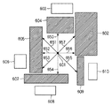
図6は、平面Ptによる仮想空間の断面図である。同図において601が重心位置Gtを示す。602〜610はそれぞれ、操作対象仮想物体以外の仮想物体である。650〜657はそれぞれ、重心位置Gtからのびる平面Pt上の半直線である。同図では8本の半直線を求めている。即ち、半直線間を45度ずつあけているが、これに限定するものではなく、半直線の数を増やすことで半直線間の角度をより密にしても良いし、半直線の数を減らすことでより疎にしても良い。
FIG. 6 is a cross-sectional view of the virtual space taken along the plane Pt. In the figure,
図6の場合、上記ステップS704では、係る8本の半直線について求めることになる。そしてステップS705では、各半直線について、重心位置Gtから最初に交差する仮想物体を特定し、特定した仮想物体の部品IDをリストに登録する。 In the case of FIG. 6, in step S704, such eight half lines are obtained. In step S705, for each half line, the virtual object that first intersects from the center of gravity position Gt is specified, and the part ID of the specified virtual object is registered in the list.
例えば、半直線650の場合、半直線650と最初に交差するのは仮想物体604である。従ってこの場合、仮想物体604の部品IDをリストに登録する。また、半直線651の場合、半直線651と最初に交差するのは仮想物体605である。従ってこの場合、仮想物体605の部品IDをリストに登録する。また、半直線652,653の場合、半直線652,653と最初に交差するのは仮想物体605である。しかし、仮想物体605の部品IDは既にリストに登録されているので、リストへの部品IDの登録処理は行わない。
For example, in the case of the
このような処理を全ての半直線について行うと、仮想物体602,604,605,607,609の部品IDはリストに登録され、それ以外の仮想物体の部品IDはリストには登録されない。即ち、仮想物体602,604,605,607,609以外の仮想物体については、操作対象仮想物体との干渉判定の対象にはならないことになる。
When such processing is performed for all the half lines, the component IDs of the
このようにして、各半直線について、最初に交差する仮想物体を特定し、特定した仮想物体の部品IDをリストに登録する。そしてこのリストに登録された部品IDを有する仮想物体は、上記ステップS304で、操作対象仮想物体との干渉判定処理を行う対象となる。 In this way, for each half line, the virtual object that intersects first is specified, and the part ID of the specified virtual object is registered in the list. Then, the virtual object having the component ID registered in the list is a target to be subjected to the interference determination process with the operation target virtual object in step S304.
なお、ステップS705で行う、直線と交差する仮想物体の検出は、例えばMercury社のシーングラフライブラリOpen Inventorを用いて実現することが出来る。 Note that the detection of the virtual object that intersects with the straight line performed in step S705 can be realized by using, for example, Mercury's scene graph library Open Inventor.
図7に戻って次にステップS706では、ステップS704で求めた複数本の半直線のそれぞれについてステップS705における処理を行ったか否かをチェックする。係るチェックの結果、全てについて行っていない場合には処理をステップS705に戻し、未だ処理対象となっていない半直線を1つを選択し、選択した半直線Lと最初に交差する仮想物体の部品IDを特定する処理を行う。 Returning to FIG. 7, in step S706, it is checked whether or not the processing in step S705 has been performed for each of the plurality of half lines obtained in step S704. As a result of checking, if not all of them have been performed, the process returns to step S705 to select one half line that has not yet been processed, and the part of the virtual object that first intersects with the selected half line L A process for specifying the ID is performed.
一方、全てについて行った場合には、処理をステップS707に進める。ステップS707では、変数tにΔtを加算する処理を行う。そしてステップS708では、変数tが示す時刻が、上記ステップS301における記録処理の終了時刻Tよりも前(小さい)か否かをチェックする。このチェックの結果、t>Tである場合には本処理を終了し、t≦Tである場合には処理をステップS702に戻し、以降の処理を繰り返す。 On the other hand, if all the processes have been performed, the process proceeds to step S707. In step S707, a process of adding Δt to the variable t is performed. In step S708, it is checked whether or not the time indicated by the variable t is earlier (smaller) than the recording processing end time T in step S301. As a result of this check, if t> T, the present process is terminated. If t ≦ T, the process returns to step S702, and the subsequent processes are repeated.
以上の説明により、本実施形態によれば、操作対象仮想物体との干渉判定となる仮想物体の数を軽減させることができるので、干渉判定処理、ひいては、仮想空間を体感させるための処理全体を高速化することが出来る。 As described above, according to the present embodiment, since the number of virtual objects that are to be subjected to interference determination with the operation target virtual object can be reduced, the interference determination processing, and thus the entire processing for experiencing the virtual space, can be performed. The speed can be increased.
また、記録モードの設定時には干渉判定を行わないため、処理の負荷を軽減することができる。 In addition, since the interference determination is not performed when the recording mode is set, the processing load can be reduced.
そしてこれらにより、作業者の対話的操作を容易にすることが出来る。 And these can make an operator's interactive operation easy.
なお、上記説明において操作対象仮想物体の重心位置の代わりに、操作対象仮想物体を包含する直方体などの立体の中心位置を用いても良い。 In the above description, the center position of a solid such as a rectangular parallelepiped including the operation target virtual object may be used instead of the center of gravity position of the operation target virtual object.
また、本実施形態では、操作対象仮想物体の重心位置からのびる半直線と交差する全ての仮想物体を、操作対象仮想物体との干渉判定の対象とした。しかし、操作対象仮想物体の重心位置からのびる半直線と交差する全ての仮想物体のうち、操作対象仮想物体の重心位置から所定の距離以内に配置されている仮想物体を、操作対象仮想物体との干渉判定の対象としても良い。 Further, in the present embodiment, all virtual objects that intersect with a half line extending from the center of gravity of the operation target virtual object are targets for interference determination with the operation target virtual object. However, among all virtual objects that intersect with the half line extending from the center of gravity position of the operation target virtual object, virtual objects arranged within a predetermined distance from the center of gravity position of the operation target virtual object are It is good also as an object of interference judgment.
また、1本の半直線と交差する仮想物体を選択するのではなく、所定本数以上の半直線と交差する仮想物体を、操作対象仮想物体との干渉判定の対象として選択するようにしても良い。 Further, instead of selecting a virtual object that intersects one half line, a virtual object that intersects a predetermined number or more of the half lines may be selected as a target for interference determination with the operation target virtual object. .
また、本実施形態では、記録モードの設定後、Δt毎の操作対象仮想物体の重心位置姿勢を、記録時刻とセットにして操作履歴として記録している。しかし、操作対象仮想物体の重心位置が所定の距離移動する毎に、その位置姿勢と記録時刻とをセットにして操作履歴として記録するようにしても良い。 In the present embodiment, after setting the recording mode, the gravity center position / posture of the operation target virtual object for each Δt is recorded as an operation history as a set with the recording time. However, each time the center of gravity of the operation target virtual object moves a predetermined distance, the position and orientation and the recording time may be set and recorded as an operation history.
また、本実施形態では、記録モードの設定時には操作対象仮想物体とその他の仮想物体との干渉判定は行わないものとした。しかし記録モード時には、記録モードが解除された後に行う干渉判定処理よりも簡便な方法を用いた干渉判定処理を行うようにしても良い。そして記録モード時に操作対象仮想物体と干渉した仮想物体の部品IDを上記リストに登録するようにしても良い。 In the present embodiment, it is assumed that when the recording mode is set, interference determination between the operation target virtual object and other virtual objects is not performed. However, in the recording mode, an interference determination process using a simpler method than the interference determination process performed after the recording mode is canceled may be performed. Then, the part ID of the virtual object that interferes with the operation target virtual object in the recording mode may be registered in the list.
[第2の実施形態]
以下では、本実施形態が第1の実施形態とは異なる点のみについて説明する。
[Second Embodiment]
Below, only the point from which this embodiment is different from 1st Embodiment is demonstrated.
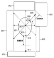
図8は、平面Ptによる仮想空間の断面図である。本実施形態では、操作対象仮想物体との干渉判定の対象とする仮想物体を選択する為の処理が、以下説明する点で第1の実施形態とは異なる。 FIG. 8 is a cross-sectional view of the virtual space taken along the plane Pt. In the present embodiment, the process for selecting a virtual object to be subjected to interference determination with the operation target virtual object is different from the first embodiment in the points described below.
同図において801は操作対象仮想物体、802〜806はそれぞれ操作対象仮想物体以外の仮想物体である。また、807は操作対象仮想物体の重心位置を示す。
In the figure,
本実施形態でも第1の実施形態と同様に、操作対象仮想物体の重心位置から放射状に半直線を設定する。しかし本実施形態では半直線設定後先ず、半直線が操作対象仮想物体と交差した点の位置と、操作対象仮想物体以外の仮想物体と交差した点の位置とを求める。例えば半直線851の場合、半直線が操作対象仮想物体と交差した点の位置は808で示されており、操作対象仮想物体以外の仮想物体と交差した点の位置は809で示されている。そして次にこの求めた2点間の距離を求める。図8では点808と点809との間の距離を求める。そして求めた距離が距離閾値以下であれば、この仮想物体を操作対象仮想物体との干渉判定の対象とする。同図では、点808と点809との間の距離は距離閾値以下であるので、仮想物体802は操作対象仮想物体との干渉判定の対象として選択される。
In the present embodiment, similarly to the first embodiment, a half line is set radially from the center of gravity of the operation target virtual object. However, in the present embodiment, after setting the half line, first, the position of the point where the half line intersects with the operation target virtual object and the position of the point where the half object intersects with the virtual object other than the operation target virtual object are obtained. For example, in the case of the
一方、半直線852の場合、操作対象仮想物体と交差する点810と、この半直線852が仮想物体805と交差する点811との間の距離は距離閾値以下ではないので、仮想物体805は、操作対象仮想物体との干渉判定の対象としては選択しない。
On the other hand, in the case of the
このように、本実施形態では、操作対象仮想物体の重心位置からのびる半直線が操作対象仮想物体と交差する点と、この半直線が交差する仮想物体におけるこの交差点との間の距離を求める。そして求めた距離が閾値以下であれば、この仮想物体を操作対象仮想物体との干渉判定の対象として選択する。 Thus, in this embodiment, the distance between the point where the half line extending from the center of gravity of the operation target virtual object intersects the operation target virtual object and the intersection of the virtual object where the half line intersects is obtained. If the obtained distance is equal to or smaller than the threshold value, this virtual object is selected as a target for interference determination with the operation target virtual object.
なお、操作対象仮想物体がその他の仮想物体と既に干渉していた場合には、この仮想物体と操作対象仮想物体との間の距離(それぞれの仮想物体における半直線との交差点間の距離)には負の符号を付ける。このようにすることにより、交点間の距離が必ず距離閾値以下となるので、操作対象仮想物体と干渉している仮想物体は必ず干渉判定対象として選択される。 If the operation target virtual object has already interfered with other virtual objects, the distance between the virtual object and the operation target virtual object (the distance between the intersections of the half lines of the respective virtual objects) Has a negative sign. By doing so, the distance between the intersections is always equal to or smaller than the distance threshold value, so that the virtual object that interferes with the operation target virtual object is always selected as the interference determination target.
なお本実施形態では、操作対象仮想物体を仮想空間内で移動させる場合に、この操作対象仮想物体との干渉判定対象としての仮想物体を特定する為には、図3のフローチャートに従った処理を行う。しかし、ステップS303における処理のみが第1の実施形態とは異なる。 In this embodiment, when the operation target virtual object is moved in the virtual space, the process according to the flowchart of FIG. 3 is performed in order to specify the virtual object as the interference determination target with the operation target virtual object. Do. However, only the processing in step S303 is different from the first embodiment.
図9は、本実施形態に係るステップS303における処理のフローチャートである。同図において図7に示したステップと同じステップについては同じステップ番号を付けており、その説明は省略する。 FIG. 9 is a flowchart of the process in step S303 according to the present embodiment. In the figure, the same steps as those shown in FIG. 7 are denoted by the same step numbers, and the description thereof is omitted.
ステップS901では、ステップS704で設定した複数の半直線のうち1つを選択し、選択した半直線と操作対象仮想物体との交点のうち、重心位置Gtから最も遠い点Mを求める。次にステップS902では、操作対象仮想物体以外の複数の仮想物体のうち、この半直線と交差する仮想物体を特定し、特定した仮想物体の部品IDと、交差した点のうち最も点Mに近い点の座標位置とをセットにしてメモリ202に格納する。
In step S901, one of the plurality of half lines set in step S704 is selected, and a point M farthest from the center of gravity position Gt is obtained from the intersections of the selected half line and the operation target virtual object. In step S902, a virtual object that intersects with the half-line is identified from among a plurality of virtual objects other than the operation target virtual object, and the component ID of the identified virtual object is closest to the point M among the intersected points. The coordinate position of the point is set and stored in the
次にステップS903では、ステップS902でメモリ202に格納した1以上のセット中の座標位置を参照し、点Mとの距離が閾値未満である座標位置とセットになっている部品IDを特定する。そしてこの特定した部品IDを第1の実施形態と同様に、操作対象仮想物体との干渉判定の対象としての仮想物体の部品IDを登録するためのリストに登録する。
Next, in step S903, the coordinate position in one or more sets stored in the
以上の処理を行うことで、操作対象仮想物体の大きさを考慮して、操作対象仮想物体との干渉判定の対象を選択することができる。従って、操作対象仮想物体と干渉する可能性の高い仮想物体のみを、干渉判定の対象として選択することができるので、更に、処理全体を高速化することが可能である。 By performing the above processing, it is possible to select a target for interference determination with the operation target virtual object in consideration of the size of the operation target virtual object. Therefore, only a virtual object that is highly likely to interfere with the operation target virtual object can be selected as an interference determination target, and the overall processing can be further speeded up.
なお、上記距離閾値は予め定められた固定値としても良いし、ユーザがキーボード206やマウス207を用いて適宜設定しても良い。
Note that the distance threshold value may be a predetermined fixed value, or may be set as appropriate by the user using the
[第3の実施形態]
第1,2の実施形態では、1回の記録モードにおける記録処理の結果得られる操作履歴を用いて、操作対象仮想物体との干渉判定の対象を選択している。しかし、複数回の記録処理により得られる複数の操作履歴を用いて、操作対象仮想物体との干渉判定の対象を選択しても良い。
[Third Embodiment]
In the first and second embodiments, an operation history obtained as a result of recording processing in one recording mode is used to select a target for interference determination with an operation target virtual object. However, a target for interference determination with the operation target virtual object may be selected using a plurality of operation histories obtained by a plurality of recording processes.
その場合、それぞれの操作履歴について第1実施形態、若しくは第2の実施形態を適用する。これにより、操作対象仮想物体の動かし方についてより多くのバリエーションを反映して干渉判定対象が選択されることになる。その結果、干渉判定対象を限定したことによる判定の抜けを防ぐことが出来る。 In that case, the first embodiment or the second embodiment is applied to each operation history. As a result, the interference determination target is selected reflecting more variations in how to move the operation target virtual object. As a result, it is possible to prevent the omission of determination due to limiting the interference determination target.
また、操作対象仮想物体以外の仮想物体毎に、何れかの方法でもって干渉判定対象として選択された回数をカウントしておき、そのカウント値が所定値以上の仮想物体を、最終的に操作対象仮想物体との干渉判定対象とするようにしても良い。この場合、操操作対象仮想物体が稀にしか通らない軌跡近傍における仮想物体を干渉判定対象の選定から外すことになり、効率的に干渉判定対象を限定することが出来る。 In addition, for each virtual object other than the operation target virtual object, the number of times selected as an interference determination target by any method is counted, and a virtual object whose count value is equal to or greater than a predetermined value is finally determined as the operation target. You may make it make it a target of interference determination with a virtual object. In this case, the virtual object in the vicinity of the trajectory through which the manipulation target virtual object rarely passes is excluded from the selection of the interference determination target, and the interference determination target can be efficiently limited.
なお、記録処理回数は固定ではなく、変更可能としてもよい。 Note that the number of recording processes is not fixed and may be changed.
[第4の実施形態]
第2の実施形態では、各半直線に対して操作対象物体と静止物体との距離を閾値と比較している。これに替えて、静止物体の各部品について、各部品と操作対象物体との距離の平均を算出し、平均距離が所定の閾値未満の部品を干渉判定対象として選択する。
[Fourth Embodiment]
In the second embodiment, the distance between the operation target object and the stationary object is compared with a threshold for each half line. Instead, the average of the distance between each part and the operation target object is calculated for each part of the stationary object, and a part whose average distance is less than a predetermined threshold is selected as an interference determination target.
更に、第3の実施形態で説明したように、複数回の記録処理でもって得られる複数の操作履歴を用いて、各操作履歴に対する平均距離を求め、更に全ての操作履歴について求めた平均距離の更に平均距離(第2の平均距離)を求める。そして、第2の平均距離以下の距離である仮想物体を、操作対象仮想物体との干渉判定対象として選択する。 Furthermore, as described in the third embodiment, an average distance for each operation history is obtained using a plurality of operation histories obtained by a plurality of recording processes, and the average distance obtained for all operation histories is further calculated. Further, an average distance (second average distance) is obtained. Then, a virtual object having a distance equal to or less than the second average distance is selected as an interference determination target with the operation target virtual object.
係る構成によれば、操作対象仮想物体が稀にしか仮想物体の近傍を通らない場合、この仮想物体を干渉判定対象の選定から外すことになり、効率的に干渉判定対象を限定することが出来る。 According to this configuration, when the operation target virtual object rarely passes through the vicinity of the virtual object, the virtual object is excluded from the selection of the interference determination target, and the interference determination target can be efficiently limited. .
[第5の実施形態]
上記各実施形態では、操作対象仮想物体との干渉判定対象の単位を、仮想物体とした。しかし、干渉判定対象を、仮想物体の構成要素としても良い。例えば、仮想物体がポリゴンで構成されている場合、操作対象仮想物体との干渉判定対象の単位をポリゴンとしても良い。
[Fifth Embodiment]
In each of the above embodiments, the unit of the interference determination target with the operation target virtual object is the virtual object. However, the interference determination target may be a component of the virtual object. For example, when the virtual object is composed of polygons, the unit of the collision determination target with the operation target virtual object may be a polygon.
例えば第1の実施形態の場合、半直線と交差する点を含むポリゴンを、操作対象仮想物体との干渉判定対象とする。 For example, in the case of the first embodiment, a polygon including a point that intersects with a half line is set as an interference determination target with the operation target virtual object.
係る構成によれば、干渉判定対象の範囲をさらに限定することになり、干渉判定処理の高速化が図られる。 According to such a configuration, the range of the interference determination target is further limited, and the speed of the interference determination process can be increased.
また、仮想物体毎に、操作対象仮想物体との干渉判定対象の単位を、仮想物体本体とするのか、構成要素とするのかをユーザが適宜キーボード206やマウス207を用いて設定しても良い。
Further, for each virtual object, the user may appropriately set whether the unit of the interference determination target with the operation target virtual object is the virtual object body or the constituent element using the
[第6の実施形態]
操作対象仮想物体との干渉判定対象として選択された仮想物体(構成要素)と、選択されていない仮想物体(構成要素)とを視覚的に区別させるために、前者と後者とで表示方法を異ならせても良い。例えば、一方と他方とで表示色を変えても良いし、前者を不透明、後者を半透明で描画しても良いし、前者のみを平面パッチに赤色でワイヤフレームを重畳表示するようにしても良い。
[Sixth Embodiment]
In order to visually distinguish between a virtual object (component) selected as a target for interference with the operation target virtual object and a virtual object (component) not selected, the display method is different between the former and the latter. May be allowed. For example, the display color may be changed between one and the other, the former may be rendered opaque and the latter may be rendered translucent, or only the former may be displayed in red on a plane patch in a superimposed manner. good.
[第7の実施形態]
上記各実施形態では、操作対象仮想物体以外の仮想物体は静止しているものとしたが、これに限定するものではなく、位置、姿勢、サイズが適宜変更されても良い。
[Seventh Embodiment]
In each of the above embodiments, the virtual objects other than the operation target virtual object are stationary. However, the present invention is not limited to this, and the position, posture, and size may be changed as appropriate.
この場合、記録モードでは、操作対象仮想物体の重心位置姿勢、記録時刻に加え、そのときの各仮想物体の位置、姿勢、拡大/縮小率(オリジナルのサイズに対する拡大/縮小率)をセットにして記録する。 In this case, in the recording mode, in addition to the center-of-gravity position and orientation of the operation target virtual object and the recording time, the position, orientation and enlargement / reduction ratio (enlargement / reduction ratio with respect to the original size) of each virtual object at that time are set. Record.
そして、記録時刻tにおける「操作対象仮想物体との干渉判定対象」を選択する際、先ず、記録時刻tにおける各仮想物体の位置、姿勢、拡大/縮小率に基づいて各仮想物体の位置姿勢、サイズを変更する。そして、上記各実施形態で説明した「操作対象仮想物体との干渉判定対象選択処理」を行う。 Then, when selecting “interference determination target with the operation target virtual object” at the recording time t, first, based on the position, orientation, and enlargement / reduction ratio of each virtual object at the recording time t, Change the size. Then, the “interference determination target selection process with the operation target virtual object” described in the above embodiments is performed.
もちろん、記録モードで、操作対象仮想物体の重心位置姿勢、記録時刻に加え、操作対象仮想物体の拡大/縮小率をセットにして記録しても良い。これにより、記録時刻tにおける「操作対象仮想物体との干渉判定対象」を選択する際、先ず、記録時刻tにおける操作対象仮想物体の拡大/縮小率に基づいて操作対象仮想物体のサイズを変更する。そして、上記各実施形態で説明した「操作対象仮想物体との干渉判定対象選択処理」を行う。係る構成によれば、操作対象仮想物体のサイズは適宜変更しても良いことになる。 Of course, in the recording mode, in addition to the center-of-gravity position and orientation of the operation target virtual object and the recording time, the enlargement / reduction ratio of the operation target virtual object may be recorded as a set. Thus, when selecting “interference determination target with the operation target virtual object” at the recording time t, first, the size of the operation target virtual object is changed based on the enlargement / reduction ratio of the operation target virtual object at the recording time t. . Then, the “interference determination target selection process with the operation target virtual object” described in the above embodiments is performed. According to such a configuration, the size of the operation target virtual object may be changed as appropriate.
また、操作対象仮想物体は1つに限定するものではなく、複数であっても良い。この場合、それぞれの操作対象仮想物体に対して上記各実施形態を適用すればよい。 Further, the number of operation target virtual objects is not limited to one, and may be plural. In this case, the embodiments described above may be applied to the respective operation target virtual objects.
また、上記各実施形態は適宜組み合わせて用いても良い。 The above embodiments may be used in appropriate combination.
[その他の実施形態]
また、本発明の目的は、以下のようにすることによって達成されることはいうまでもない。即ち、前述した実施形態の機能を実現するソフトウェアのプログラムコードを記録した記録媒体(または記憶媒体)を、システムあるいは装置に供給する。そして、そのシステムあるいは装置のコンピュータ(またはCPUやMPU)が記録媒体に格納されたプログラムコードを読み出し実行する。この場合、記録媒体から読み出されたプログラムコード自体が前述した実施形態の機能を実現することになり、そのプログラムコードを記録した記録媒体は本発明を構成することになる。
[Other Embodiments]
Needless to say, the object of the present invention can be achieved as follows. That is, a recording medium (or storage medium) in which a program code of software that realizes the functions of the above-described embodiments is recorded is supplied to the system or apparatus. Then, the computer (or CPU or MPU) of the system or apparatus reads and executes the program code stored in the recording medium. In this case, the program code itself read from the recording medium realizes the functions of the above-described embodiment, and the recording medium on which the program code is recorded constitutes the present invention.
また、コンピュータが読み出したプログラムコードを実行することにより、そのプログラムコードの指示に基づき、コンピュータ上で稼働しているオペレーティングシステム(OS)などが実際の処理の一部または全部を行う。その処理によって前述した実施形態の機能が実現される場合も含まれることは言うまでもない。 Further, by executing the program code read by the computer, an operating system (OS) or the like running on the computer performs part or all of the actual processing based on the instruction of the program code. Needless to say, the process includes the case where the functions of the above-described embodiments are realized.
さらに、記録媒体から読み出されたプログラムコードが、コンピュータに挿入された機能拡張カードやコンピュータに接続された機能拡張ユニットに備わるメモリに書込まれたとする。その後、そのプログラムコードの指示に基づき、その機能拡張カードや機能拡張ユニットに備わるCPUなどが実際の処理の一部または全部を行い、その処理によって前述した実施形態の機能が実現される場合も含まれることは言うまでもない。 Furthermore, it is assumed that the program code read from the recording medium is written in a memory provided in a function expansion card inserted into the computer or a function expansion unit connected to the computer. After that, based on the instruction of the program code, the CPU included in the function expansion card or function expansion unit performs part or all of the actual processing, and the function of the above-described embodiment is realized by the processing. Needless to say.
本発明を上記記録媒体に適用する場合、その記録媒体には、先に説明したフローチャートに対応するプログラムコードが格納されることになる。 When the present invention is applied to the recording medium, program code corresponding to the flowchart described above is stored in the recording medium.
Claims (10)
前記情報処理装置が有する取得手段が、ユーザ操作により位置姿勢が変更可能な操作対象仮想物体の位置姿勢を計測する計測手段から、該計測された位置姿勢を示す位置姿勢情報を取得する取得工程と、
前記情報処理装置が有する指示手段が、記録モードの設定、記録モードの解除、の何れかを指示する指示工程と、
前記情報処理装置が有する記録手段が、前記記録モードが設定されている間は、前記取得工程で取得した位置姿勢情報をメモリに記録し、前記記録モードが解除されると、当該記録を終了する記録工程と、
前記情報処理装置が有する選択手段が、前記記録モードが解除されると、前記操作対象仮想物体と同じ仮想空間中に配置されている複数の仮想要素のうち、前記メモリに記録されている位置姿勢情報群が示す前記操作対象仮想物体の移動軌跡の近傍に位置する仮想要素を、前記操作対象仮想物体との干渉判定の対象として選択する選択工程と、
前記情報処理装置が有する干渉判定手段が、前記選択工程で選択した仮想要素と、前記操作対象仮想物体との干渉判定処理を行う干渉判定工程と、
前記情報処理装置が有する出力手段が、前記干渉判定工程による結果を出力する出力工程と
を備えることを特徴とする情報処理方法。 An information processing method performed by an information processing apparatus,
An acquisition step in which an acquisition unit included in the information processing apparatus acquires position and orientation information indicating the measured position and orientation from a measurement unit that measures the position and orientation of an operation target virtual object whose position and orientation can be changed by a user operation; ,
An instruction step in which the instruction means included in the information processing apparatus instructs one of setting of a recording mode and cancellation of the recording mode;
The recording means included in the information processing apparatus records the position / orientation information acquired in the acquisition step in the memory while the recording mode is set, and ends the recording when the recording mode is released. Recording process;
When the selection mode of the information processing apparatus is released from the recording mode, a position and orientation recorded in the memory among a plurality of virtual elements arranged in the same virtual space as the operation target virtual object A selection step of selecting a virtual element located in the vicinity of the movement trajectory of the operation target virtual object indicated by the information group as a target of interference determination with the operation target virtual object;
An interference determination step in which the interference determination means of the information processing apparatus performs an interference determination process between the virtual element selected in the selection step and the operation target virtual object;
An information processing method comprising: an output unit included in the information processing apparatus including an output step of outputting a result of the interference determination step.
前記情報処理装置が有する表示制御手段が、前記操作対象仮想物体、及び前記操作対象仮想物体以外の仮想要素を表示装置に表示させる表示制御工程を備え、
前記表示制御工程では、前記選択工程で選択された仮想要素と選択されていない仮想要素とを異なる表示方法で表示することを特徴とする請求項1乃至5の何れか1項に記載の情報処理方法。 Furthermore,
The display control means included in the information processing apparatus includes a display control step of causing the display device to display the operation target virtual object and a virtual element other than the operation target virtual object,
6. The information processing according to claim 1, wherein the display control step displays the virtual element selected in the selection step and the virtual element not selected in a different display method. Method.
前記情報処理装置が有する第2の干渉判定手段が、前記記録モードが設定されている間は、前記干渉判定工程で行う干渉判定処理よりも簡便な干渉判定方法で、前記操作対象仮想物体と前記複数の仮想要素との干渉判定処理を行う第2の干渉判定工程と、
前記情報処理装置が有する第2の出力手段が、前記第2の干渉判定工程による結果を出力する第2の出力工程と
を備えることを特徴とする請求項1乃至6の何れか1項に記載の情報処理方法。 Furthermore,
While the second interference determination unit of the information processing apparatus is in the recording mode, the operation target virtual object and the operation object virtual object can be compared with the interference determination method that is simpler than the interference determination process performed in the interference determination step. A second interference determination step for performing interference determination processing with a plurality of virtual elements;
The second output unit included in the information processing apparatus includes: a second output step that outputs a result of the second interference determination step. Information processing method.
ユーザ操作により位置姿勢が変更可能な操作対象仮想物体の位置姿勢を計測する計測手段から、該計測された位置姿勢を示す位置姿勢情報を取得する取得手段と、
記録モードの設定、記録モードの解除、の何れかを指示する指示手段と、
前記記録モードが設定されている間は、前記取得手段で取得した位置姿勢情報をメモリに記録し、前記記録モードが解除されると、当該記録を終了する記録手段と、
前記記録モードが解除されると、前記操作対象仮想物体と同じ仮想空間中に配置されている複数の仮想要素のうち、前記メモリに記録されている位置姿勢情報群が示す前記操作対象仮想物体の移動軌跡の近傍に位置する仮想要素を、前記操作対象仮想物体との干渉判定の対象として選択する選択手段と、
前記選択手段で選択した仮想要素と、前記操作対象仮想物体との干渉判定処理を行う干渉判定手段と、
前記干渉判定手段による結果を出力する出力手段と
を備えることを特徴とする情報処理装置。 An information processing apparatus,
An acquisition unit that acquires position and orientation information indicating the measured position and orientation from a measurement unit that measures the position and orientation of an operation target virtual object whose position and orientation can be changed by a user operation;
Instructing means for instructing either recording mode setting or recording mode cancellation;
While the recording mode is set, the position and orientation information acquired by the acquisition unit is recorded in a memory, and when the recording mode is released, a recording unit that ends the recording;
When the recording mode is canceled, among the plurality of virtual elements arranged in the same virtual space as the operation target virtual object, the operation target virtual object indicated by the position and orientation information group recorded in the memory is displayed. Selection means for selecting a virtual element located in the vicinity of the movement locus as a target for interference determination with the operation target virtual object;
Interference determination means for performing interference determination processing between the virtual element selected by the selection means and the operation target virtual object;
An information processing apparatus comprising: output means for outputting a result of the interference determination means.
Priority Applications (3)
| Application Number | Priority Date | Filing Date | Title |
|---|---|---|---|
| JP2006236757A JP4986543B2 (en) | 2006-08-31 | 2006-08-31 | Information processing method and information processing apparatus |
| PCT/JP2007/067096 WO2008026752A1 (en) | 2006-08-31 | 2007-08-28 | Information processing method and information processing apparatus |
| US12/439,179 US8145460B2 (en) | 2006-08-31 | 2007-08-28 | Information processing method and information processing apparatus |
Applications Claiming Priority (1)
| Application Number | Priority Date | Filing Date | Title |
|---|---|---|---|
| JP2006236757A JP4986543B2 (en) | 2006-08-31 | 2006-08-31 | Information processing method and information processing apparatus |
Publications (3)
| Publication Number | Publication Date |
|---|---|
| JP2008059375A JP2008059375A (en) | 2008-03-13 |
| JP2008059375A5 JP2008059375A5 (en) | 2009-10-15 |
| JP4986543B2 true JP4986543B2 (en) | 2012-07-25 |
Family
ID=39136031
Family Applications (1)
| Application Number | Title | Priority Date | Filing Date |
|---|---|---|---|
| JP2006236757A Expired - Fee Related JP4986543B2 (en) | 2006-08-31 | 2006-08-31 | Information processing method and information processing apparatus |
Country Status (3)
| Country | Link |
|---|---|
| US (1) | US8145460B2 (en) |
| JP (1) | JP4986543B2 (en) |
| WO (1) | WO2008026752A1 (en) |
Families Citing this family (4)
| Publication number | Priority date | Publication date | Assignee | Title |
|---|---|---|---|---|
| JP5628083B2 (en) * | 2011-04-13 | 2014-11-19 | 株式会社日立製作所 | Computer system and assembly animation generation method |
| JP5834589B2 (en) * | 2011-07-27 | 2015-12-24 | マツダ株式会社 | Method and apparatus for automatically verifying gaps between parts |
| KR20140010616A (en) * | 2012-07-16 | 2014-01-27 | 한국전자통신연구원 | Apparatus and method for processing manipulation of 3d virtual object |
| JP2019008623A (en) | 2017-06-27 | 2019-01-17 | キヤノン株式会社 | Information processing apparatus, information processing apparatus control method, computer program, and storage medium |
Family Cites Families (19)
| Publication number | Priority date | Publication date | Assignee | Title |
|---|---|---|---|---|
| US5575636A (en) | 1994-06-21 | 1996-11-19 | Praxair Technology, Inc. | Porous non-fouling nozzle |
| US5640335A (en) * | 1995-03-23 | 1997-06-17 | Exa Corporation | Collision operators in physical process simulation |
| JP3378726B2 (en) | 1996-05-24 | 2003-02-17 | 富士通株式会社 | Machine design / manufacturing process support device |
| JPH10307935A (en) * | 1997-05-09 | 1998-11-17 | Hitachi Ltd | Generation method and interference check method for agree-dimensional model |
| JP3396414B2 (en) * | 1997-12-15 | 2003-04-14 | 株式会社日立製作所 | Proximity part search method and search device |
| JP3383563B2 (en) * | 1997-12-18 | 2003-03-04 | 富士通株式会社 | Object movement simulation device |
| JP2000200361A (en) * | 1998-08-07 | 2000-07-18 | Sega Enterp Ltd | Image processor and information recording medium |
| JP2000350865A (en) * | 1999-06-11 | 2000-12-19 | Mr System Kenkyusho:Kk | Game device for composite real space, image processing method therefor and program storage medium |
| JP2001067381A (en) * | 1999-08-30 | 2001-03-16 | Canon Inc | Device and method for checking interference, and storing medium |
| JP4724307B2 (en) * | 2001-04-03 | 2011-07-13 | キヤノン株式会社 | Route design support device, control method, and program |
| US7191104B2 (en) * | 2002-07-11 | 2007-03-13 | Ford Global Technologies, Llc | Method of real-time collision detection between solid geometric models |
| JP2004094750A (en) * | 2002-09-02 | 2004-03-25 | Ricoh Co Ltd | Three-dimensional configuration processor, interference model detecting method, program and storage medium |
| FR2861857B1 (en) * | 2003-10-29 | 2006-01-20 | Snecma Moteurs | DISPLACEMENT OF A VIRTUAL ARTICULATED OBJECT IN A VIRTUAL ENVIRONMENT BY AVOIDING INTERNAL COLLISIONS BETWEEN THE ARTICULATED ELEMENTS OF THE ARTICULATED OBJECT |
| FR2861858B1 (en) * | 2003-10-29 | 2014-09-05 | Snecma Moteurs | MOVING A VIRTUAL ARTICULATED OBJECT INTO A VIRTUAL ENVIRONMENT BY AVOIDING COLLISIONS BETWEEN ARTICULATED OBJECT AND THE ENVIRONMENT |
| US20060192852A1 (en) * | 2005-02-09 | 2006-08-31 | Sally Rosenthal | System, method, software arrangement and computer-accessible medium for providing audio and/or visual information |
| JP4335160B2 (en) * | 2005-03-02 | 2009-09-30 | 任天堂株式会社 | Collision judgment program and collision judgment device |
| JP4739002B2 (en) * | 2005-06-30 | 2011-08-03 | キヤノン株式会社 | Image processing method and image processing apparatus |
| JP2007164252A (en) * | 2005-12-09 | 2007-06-28 | Sony Computer Entertainment Inc | System managing object in virtual space |
| JP5030132B2 (en) * | 2006-01-17 | 2012-09-19 | 任天堂株式会社 | GAME PROGRAM AND GAME DEVICE |
-
2006
- 2006-08-31 JP JP2006236757A patent/JP4986543B2/en not_active Expired - Fee Related
-
2007
- 2007-08-28 WO PCT/JP2007/067096 patent/WO2008026752A1/en active Search and Examination
- 2007-08-28 US US12/439,179 patent/US8145460B2/en not_active Expired - Fee Related
Also Published As
| Publication number | Publication date |
|---|---|
| US20090259443A1 (en) | 2009-10-15 |
| WO2008026752A1 (en) | 2008-03-06 |
| JP2008059375A (en) | 2008-03-13 |
| US8145460B2 (en) | 2012-03-27 |
Similar Documents
| Publication | Publication Date | Title |
|---|---|---|
| US7084869B2 (en) | Methods and apparatus for detecting and correcting penetration between objects | |
| EP1808210B1 (en) | Storage medium having game program stored thereon and game apparatus | |
| JP3689226B2 (en) | Decomposition path generator | |
| US20080030461A1 (en) | Mixed reality presentation apparatus and control method thereof, and program | |
| KR101389894B1 (en) | Virtual reality simulation apparatus and method using motion capture technology and | |
| US9224247B2 (en) | Three-dimensional object processing device, three-dimensional object processing method, and information storage medium | |
| US20080231631A1 (en) | Image processing apparatus and method of controlling operation of same | |
| JP2005227876A (en) | Method and apparatus for image processing | |
| US10614590B2 (en) | Apparatus for determination of interference between virtual objects, control method of the apparatus, and storage medium | |
| JPH11184898A (en) | Object movement simulation device | |
| JP4942517B2 (en) | Collision sensing device and method | |
| EP3629302B1 (en) | Information processing apparatus, information processing method, and storage medium | |
| JP2022534639A (en) | Artificial Reality System with Finger Mapping Self-Tactile Input Method | |
| JP4986543B2 (en) | Information processing method and information processing apparatus | |
| JP2007004713A (en) | Image processing method and image processor | |
| JP5625700B2 (en) | Three-dimensional CAD program, apparatus, and three-dimensional CAD processing method | |
| CA3128614A1 (en) | Method and system for displaying a large 3d model on a remote device | |
| JP2017016376A (en) | Information processing apparatus, information processing method, and program | |
| JP4334961B2 (en) | Image generation information, information storage medium, and image generation apparatus | |
| JP2006215750A (en) | Image processing method, image processor | |
| EP4089562A1 (en) | Designing garment using style line | |
| JP2005071285A (en) | Collision detection method that change detail degree according to interaction in space and virtual space formation device using its method | |
| CN112486319B (en) | VR (virtual reality) interaction method, device, equipment and medium based on touch rendering equipment | |
| JP2006343954A (en) | Image processing method and image processor | |
| JP2007213437A (en) | Information-processing method and information-processing device |
Legal Events
| Date | Code | Title | Description |
|---|---|---|---|
| A521 | Written amendment |
Free format text: JAPANESE INTERMEDIATE CODE: A523 Effective date: 20090831 |
|
| A621 | Written request for application examination |
Free format text: JAPANESE INTERMEDIATE CODE: A621 Effective date: 20090831 |
|
| A131 | Notification of reasons for refusal |
Free format text: JAPANESE INTERMEDIATE CODE: A131 Effective date: 20111107 |
|
| A521 | Written amendment |
Free format text: JAPANESE INTERMEDIATE CODE: A523 Effective date: 20111228 |
|
| TRDD | Decision of grant or rejection written | ||
| A01 | Written decision to grant a patent or to grant a registration (utility model) |
Free format text: JAPANESE INTERMEDIATE CODE: A01 Effective date: 20120420 |
|
| A01 | Written decision to grant a patent or to grant a registration (utility model) |
Free format text: JAPANESE INTERMEDIATE CODE: A01 |
|
| A61 | First payment of annual fees (during grant procedure) |
Free format text: JAPANESE INTERMEDIATE CODE: A61 Effective date: 20120424 |
|
| FPAY | Renewal fee payment (event date is renewal date of database) |
Free format text: PAYMENT UNTIL: 20150511 Year of fee payment: 3 |
|
| LAPS | Cancellation because of no payment of annual fees |