JP4986470B2 - Sealed storage structure and lid holder for flow meter measurement unit - Google Patents
Sealed storage structure and lid holder for flow meter measurement unit Download PDFInfo
- Publication number
- JP4986470B2 JP4986470B2 JP2006032987A JP2006032987A JP4986470B2 JP 4986470 B2 JP4986470 B2 JP 4986470B2 JP 2006032987 A JP2006032987 A JP 2006032987A JP 2006032987 A JP2006032987 A JP 2006032987A JP 4986470 B2 JP4986470 B2 JP 4986470B2
- Authority
- JP
- Japan
- Prior art keywords
- shaped
- frame
- peripheral side
- outer peripheral
- lid
- Prior art date
- Legal status (The legal status is an assumption and is not a legal conclusion. Google has not performed a legal analysis and makes no representation as to the accuracy of the status listed.)
- Expired - Fee Related
Links
Images


Description
本発明は、水道メータなどの流量メータに装着された収納ケースに計測ユニットを密閉状態で収納するための密閉収納構造に関するものである。また、当該密閉収納構造に用いる蓋押えに関するものである。 The present invention relates to a sealed storage structure for storing a measurement unit in a sealed state in a storage case attached to a flow meter such as a water meter. The present invention also relates to a lid presser used for the hermetic housing structure.
流量メータ、例えば水道メータは、そのメータケース内に水道水が通過する測定室を備え、この測定室には流量に応じて回転する羽根車が配置され、羽根車の回転がメータケースに収納されている計測ユニットによって検出され、検出結果に基づき流量が計測されるように構成されている。計測ユニットは、メータケースに装着した収納ケースに密閉状態で収納され、内部に水などが浸入しないようになっている。かかる構成の水道メータが下記の特許文献1に開示されている。
A flow meter, for example, a water meter, includes a measurement chamber through which tap water passes, and an impeller that rotates according to the flow rate is disposed in the measurement chamber, and the rotation of the impeller is stored in the meter case. And the flow rate is measured based on the detection result. The measurement unit is stored in a sealed state in a storage case attached to the meter case so that water or the like does not enter inside. A water meter having such a configuration is disclosed in
当該特許文献に開示の水道メータでは、メータケースに装着したレジスタボックス(収納ケース)内に積算歯車機構などを含む計測機構が内蔵され、その上面に被せたガラス板(蓋板)が、一体ガスケット(蓋押え)によってシールされている。一体ガスケットは、プラスチック製の平滑なリング状平板部の下面に弾性体が一体に取り付けられ、平板部の周囲の複数の箇所には、レジスタボックスに取り付けるための張り出し部が形成された構成となっている。張り出し部が係合用の爪として機能して、一体ガスケットがレジスタボックスに固定され、当該一体ガスケットとレジスタボックスの間にガラス板が挟持された状態になる。
このような従来の蓋押えは、複数の張り出し部によって収納ケースの側に固定されているだけなので、蓋板の押し付け力が弱く、シール性に劣るという課題がある。このため、収納ケースに計測ユニットを入れてメータケースに取り付けるまでの間は、収納ケース内部にシルカゲルなどの吸湿材を入れて当該収納ケースの開口部にガラス板を取り付けて封鎖し、内部を乾燥状態に保持する必要がある。 Since such a conventional lid presser is only fixed to the storage case side by a plurality of overhang portions, there is a problem that the pressing force of the lid plate is weak and the sealing performance is poor. For this reason, until the measuring unit is put in the storage case and attached to the meter case, a hygroscopic material such as silk gel is put inside the storage case, and a glass plate is attached to the opening of the storage case and sealed, and the inside is dried. Must be kept in state.
本発明の課題は、このような点に鑑みて、シール性に優れた流量メータの計測ユニットの密閉収納構造、および、当該密閉収納構造に用いる蓋押えを提案することにある。 In view of these points, an object of the present invention is to propose a sealed housing structure for a measurement unit of a flow meter excellent in sealing performance and a lid presser used for the sealed housing structure.
上記の課題を解決するために、本発明の流量メータの計測ユニットの密閉収納構造は、
流量メータケースに装着される流量計測ユニット収納用の収納ケースと、
前記収納ケースの上端開口部を封鎖する蓋板と、
前記蓋板を前記収納ケースに押し付けて、当該収納ケース内を密閉状態に保持するための枠状の蓋押えと、
前記収納ケースおよび前記蓋板の間に挟み込まれる枠状の第1シール部材と、
前記蓋板および前記蓋押えの間に挟み込まれる枠状の第2シール部材とを有し、
前記蓋押えの裏面側端面には、前記蓋板を押えている枠状の内周側端面部分と、この外周側に形成された前記第2シール部材装着用の枠状凹部と、この外周側に形成された前記裏面側端面から垂直に突出している枠状突起と、この外周側に形成された外周側端面部分とが形成されており、
前記枠状突起の内周面および/または外周面には、所定の角度間隔で内側あるいは外側に突出した複数のリブが形成されており、
前記蓋板を取り囲んでいる前記収納ケースの上端面には、枠状の内周側端面部分と、前記枠状突起が嵌め込まれる枠状の嵌め込み溝と、前記蓋押えの前記外周側端面部分に当接している外周側端面部分とが形成されており、
前記凹部に装着される前記第2シール部材は、前記蓋板の外周縁部分と前記収納ケースの前記内周側端面部分に密着状態で押し付けられることを特徴としている。
In order to solve the above problems, the sealed housing structure of the measurement unit of the flow meter of the present invention is:
A storage case for storing a flow rate measurement unit attached to the flow meter case;
A lid plate for sealing the upper end opening of the storage case;
A frame-shaped lid presser for pressing the lid plate against the storage case to hold the storage case in a sealed state;
A frame-shaped first seal member sandwiched between the storage case and the cover plate;
A frame-shaped second seal member sandwiched between the lid plate and the lid presser,
A frame-shaped inner peripheral side end surface portion holding the cover plate, a frame-shaped concave portion for mounting the second seal member formed on the outer peripheral side, and an outer peripheral side of the rear surface side end surface of the lid presser A frame-like protrusion that protrudes perpendicularly from the back-side end surface formed on the outer peripheral side, and an outer peripheral side end surface portion formed on the outer peripheral side;
A plurality of ribs protruding inward or outward at predetermined angular intervals are formed on the inner peripheral surface and / or the outer peripheral surface of the frame-shaped protrusion,
The upper end surface of the storage case surrounding the lid plate has a frame-shaped inner peripheral side end surface portion, a frame-shaped fitting groove into which the frame-shaped protrusion is fitted, and the outer peripheral side end surface portion of the lid presser. The outer peripheral side end face part that is in contact with the
The second seal member mounted in the recess is pressed against the outer peripheral edge portion of the lid plate and the inner peripheral side end surface portion of the storage case in a close contact state.
一般的には、前記蓋押えはリング状の蓋押えであり、前記第1シール部材としてOリングが用いられ、前記第2シール部材としてリング状の弾性板が用いられる。 Generally, the lid retainer is a ring-shaped lid retainer, and an O-ring is used as the first seal member, and a ring-shaped elastic plate is used as the second seal member.
次に、本発明は上記構成の密閉構造に用いる蓋押えであって、
枠状本体の裏面側の端面に、枠状の内周側端面部分と、この内周側端面の外周側に形成されたシール部材装着用の枠状凹部と、この枠状凹部の外周側に形成された前記端面から垂直に突出している枠状突起と、この枠状突起の外周側に形成された外周側端面部分とが形成されており、
前記枠状突起の内周面および/または外周面には、所定の角度間隔で内側あるいは外側に突出した複数のリブが形成されていることを特徴としている。
Next, the present invention is a lid presser used in the sealing structure having the above-described configuration,
A frame-shaped inner peripheral side end surface portion, a frame-shaped concave portion for mounting a seal member formed on the outer peripheral side of the inner peripheral side end surface, and an outer peripheral side of the frame-shaped concave portion A frame-like protrusion protruding perpendicularly from the formed end face, and an outer peripheral side end face portion formed on the outer peripheral side of the frame-like protrusion;
A plurality of ribs protruding inward or outward at a predetermined angular interval are formed on the inner peripheral surface and / or outer peripheral surface of the frame-shaped protrusion.
本発明では、枠状の蓋押えの端面に形成された枠状突起が収納ケース側に形成した枠状凹部に嵌め込まれ、これによって蓋板が固定される。枠状突起の内周面あるいは外周面、またはその双方の面には、所定の角度間隔でリブが形成されている。これらのリブの高さが嵌め込み代となるので、強固に蓋押えを収納ケースに固定できる。 In the present invention, the frame-shaped protrusion formed on the end surface of the frame-shaped lid presser is fitted into the frame-shaped recess formed on the storage case side, thereby fixing the cover plate. Ribs are formed at predetermined angular intervals on the inner peripheral surface and / or outer peripheral surface of the frame-shaped protrusion. Since the height of these ribs becomes a fitting margin, the lid retainer can be firmly fixed to the storage case.
この結果、蓋押えと、蓋板および収納ケースの上端面との間に配置されている第2シール部材が強い力でこれらの間に挟持され、これらの間が確実にシールされる。また、蓋板と収納ケースの間に配置した第1シール部材もこれらの間に強い力で挟持され、これらの間が確実にシールされる。よって、収納ケース内部が確実にシールされる。 As a result, the second seal member disposed between the lid presser and the lid plate and the upper end surface of the storage case is sandwiched between them with a strong force, and the space between them is reliably sealed. Moreover, the 1st sealing member arrange | positioned between a cover plate and a storage case is also clamped between these with strong force, and between these is sealed reliably. Therefore, the inside of the storage case is securely sealed.
このため、本発明の密閉構造を採用すれば、収納ケースを確実に密閉して内部を乾燥状態に保持できる。よって、メータケースに組み付けるまで、内部に吸湿材などを入れた状態で保管しておく必要がない。 For this reason, if the sealing structure of this invention is employ | adopted, a storage case can be sealed reliably and an inside can be kept dry. Therefore, it is not necessary to store the hygroscopic material in the inside until it is assembled to the meter case.
以下に、図面を参照して、本発明を適用した水道メータケースを備えた水道メータの実施の形態を説明する。 Hereinafter, an embodiment of a water meter provided with a water meter case to which the present invention is applied will be described with reference to the drawings.
(全体構成)
図1は本実施の形態に係る水道メータの概略構成図である。水道メータ1は、ケース本体2とケース蓋3とを備えている。ケース本体2は、円形の底板部分4および円形の上端開口部5を備えた円筒部分6を有し、この円筒部分6の底板部分4側の外周面からは、水導入管部分7および水排出管部分8がそれぞれ外方に突出している。
(overall structure)
FIG. 1 is a schematic configuration diagram of a water meter according to the present embodiment. The
円筒部分6の上端開口部5には、上側から、カップ形の収納ケース20が装着されている。収納ケース20には、その上端開口部21から機械式の計測ユニット10が挿入されており、この状態で上端開口部21がガラス製の蓋板30によって封鎖されている。蓋板30はリング状の蓋押え40によって収納ケース20に密閉状態で固定されている。
A cup-
ケース本体2の上端開口部5の外周面部分には雄ねじ部9が形成されており、ケース蓋3は、収納ケース20の外周側の上端面22および、そこに固定した蓋押え40を覆う状態で、雄ねじ部9にねじ込み固定されている。なお、大型メータの場合には、ケース蓋が、ボルトなどの固定金具を用いてケース本体に固定される場合がある。
A
水導入管部分7および水排出管部分8の先端部分の外周面にはそれぞれ雄ねじ部7a、8aが形成されており、不図示の上流側水道管および下流側水道管の間に連結可能となっている。円筒部分6の内部において、その底板部分4と収納ケース20の底面部分20aの間には、円形断面の流量測定室11が区画形成されている。この流量測定室11には、流水方向に垂直なピボット12が配置され、ここには、羽根車13の軸14の下端側部分が回転自在の状態で支持されている。
Male threaded
羽根車13の軸14の上端部分には磁石15が取り付けられており、計測ユニット10の内部には、磁石15に対峙した状態でマグネット付き歯車16が配置されている。羽根車13が、流量測定室11を流れる水の流量に応じて回転すると、その軸14の回転がマグネット付き歯車16によって検出され、回転数に対応した流量値が計測される。
A
なお、収納ケース20の底面部分20aには調整器17a、17bが取り付けられている。調整器17a、17bを調整して、測定室11を流れる水流を調節することにより、流量に対応した状態で羽根車13を回転させることができる。換言すると、精度良く流量を検出することができる。
Note that
(計測ユニットの密閉収納構造)
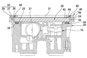
図2は、計測ユニット10が収納されている収納ケース20、蓋板30および蓋押え40を示す部分断面図である。図3(a)〜(c)はそれぞれ、蓋押え40を示す平面図、断面図および底面図である。
(Measurement unit sealed storage structure)
FIG. 2 is a partial cross-sectional view showing the
本例では、収納ケース20と蓋板30の間にはOリング50が挟み込まれている。また、蓋板30と蓋押え40の間にはリング状の弾性板60が挟み込まれている。これらOリング50および弾性板60によって、収納ケース20の内部のシール性が確保されている。弾性板60は例えばゴム製のものを用いることができる。
In this example, an O-
収納ケース20の上端開口部21はリング状段面23によって取り囲まれており、このリング状段面23は一段高い位置に形成されているリング状上端面22を備えたリング状フランジ24によって取り囲まれている。リング状段面23にはOリング装着用のリング状の凹部25が形成されており、ここにOリング50が装着されている。円形の蓋板30は、Oリング50の上から、リング状フランジ24の内側に嵌め込まれている。Oリング50を押し付けることにより、蓋板30の上面31を収納ケース20のリング状上端面22と同一高さとすることが可能となっている。
The upper end opening 21 of the
収納ケース20のリング状上端面22には、その内周側にリング状の内周側端面部分26が形成されており、これを取り囲む状態にリング状の嵌め込み溝27が形成されており、さらに、これを取り囲む状態にリング状の外周側端面部分28が形成されている。
A ring-shaped inner peripheral side
この形状のリング状上端面22に取り付けられる蓋押え40はリング状のプラスチック成形板からなるリング状本体板41を備えている。このリング状本体板41の裏面側の端面42には、その内周縁側がリング状の内周側端面部分43となっており、これを取り囲む状態に弾性板装着用のリング状凹部44が形成されている。このリング状凹部44を取り囲む状態にリング状突起45が形成され、このリング状突起45を取り囲む状態にリング状の外周側端面部分46が形成されている。
The
内周側端面部分43は、収納ケース20に取り付けた蓋板30の上面31を押し付けるための押え面である。この外側のリング状凹部44に装着されたリング状弾性板60は、蓋板30の外周縁部分および収納ケース20の内周側端面部分26に押し付けられた状態となっている。
The inner peripheral side
ここで、蓋押え40のリング状突起45は、リング状本体板41の裏面側端面42から垂直に突出しており、円周方向に連続して形成された一定厚さのものである。また、このリング状突起45の内周面45aおよび外周面45bには、等角度間隔で一定幅のリブ46a、46bが形成されている。これらのリブ46a、46bは、内周面45aおよび外周面45bに沿って端面42から垂直な方向に延びている。リンク状突起45の高さおよび厚さは、収納ケース20の側の嵌め込み溝27の深さおよび幅とほぼ同一とされており、これらのリブ46a、46bの内側および外側への突出量が嵌め込み代となっている。
Here, the ring-shaped
この構成の計測ユニットの密閉収納構造は次の手順で組み立てられる。まず、収納ケース20に計測ユニット10を入れてOリング50を装着した後に、蓋板30を取り付けて上端開口部21を封鎖する。しかる後に、蓋押え40の裏面側のリング状凹部44に弾性板60を装着し、この状態を保持して、蓋押え40のリング状突起45を収納ケース20のリング状嵌め込み溝27に嵌め込む。蓋押え40のリング状突起45を完全にリング状嵌め込み溝27に押し込むと、蓋押え40が強固に収納ケース20に固定される。また、蓋押え40によって押し付けられた蓋板30によってOリング50が押し潰されて、蓋板30と収納ケース20の間が確実にシールされた状態になる。また、蓋押え40と、収納ケース20および蓋板30との間の弾性板60が押し潰されて、これらの間が確実にシールされた状態になる。
The sealed housing structure of the measurement unit having this configuration is assembled by the following procedure. First, after putting the measuring
このように、本例では、蓋押え40のリング状突起45がその円周方向の全周に亘って収納ケース20の側のリング状嵌め込み溝27に嵌り込む。また、リング状突起45の内外周面にはリブ46a、46bが形成されており、これらによって、リング状突起45が強固に収納ケース20に固定される。この結果、確実なシール状態を形成できる。
Thus, in this example, the ring-shaped
(その他の実施の形態)
なお、上記の例は水道メータに本発明を適用したものであるが、例えば、ガスメータのメータケースに対して本発明を同様に適用することができる。さらには、水道およびガスメータ以外の流量メータに対しても本発明を同様に適用可能である。
(Other embodiments)
In addition, although said example applies this invention to a water meter, this invention is applicable similarly to the meter case of a gas meter, for example. Furthermore, the present invention can be similarly applied to flow meters other than water and gas meters.
また、上記の例では、収納ケースの上端開口部が円形であり、それに合わせて、蓋板、蓋押えもリング状のものとしてある。上端開口部が円形ではない場合には、その形状に合わせた枠状の蓋板および蓋押えを用いればよい。 In the above example, the upper end opening of the storage case is circular, and the lid plate and lid retainer are also ring-shaped in accordance with the circular opening. If the upper end opening is not circular, a frame-like lid plate and lid presser that match the shape may be used.
1 水道メータ
2 ケース本体
3 ケース蓋
4 底板部分
5 上端開口部
6 円筒部分
7 水導入管部分
8 水排出管部分
10 計測ユニット
11 測定室
13 羽根車
20 収納ケース
21 上端開口部
22 上端面
23 段面
24 フランジ
25 凹部
26 内周側端面
27 嵌め込み溝
28 外周側端面
30 蓋板
40 蓋押え
41 本体板
42 裏面側端面
43 内周側端面
44 凹部
45 リング状突起
45a 内周面
45b 外周面
46 外周側端面
46a、46b リブ
50 Oリング
60 弾性板
DESCRIPTION OF
Claims (3)
前記収納ケースの上端開口部を封鎖する蓋板と、
前記蓋板を前記収納ケースに押し付けて、当該収納ケース内を密閉状態に保持するための枠状の蓋押えと、
前記収納ケースおよび前記蓋板の間に挟み込まれる枠状の第1シール部材と、
前記蓋板および前記蓋押えの間に挟み込まれる枠状の第2シール部材とを有し、
前記蓋押えの裏面側端面には、前記蓋板を押えている枠状の内周側端面部分と、この外周側に形成された前記第2シール部材装着用の枠状凹部と、この外周側に形成された前記裏面側端面から垂直に突出している枠状突起と、この外周側に形成された外周側端面部分とが形成されており、
前記枠状突起の内周面および/または外周面には、所定の角度間隔で内側あるいは外側に突出した複数のリブが形成されており、
前記蓋板を取り囲んでいる前記収納ケースの上端面には、枠状の内周側端面部分と、前記枠状突起が嵌め込まれる枠状の嵌め込み溝と、前記蓋押えの前記外周側端面部分に当接している外周側端面部分とが形成されており、
前記凹部に装着される前記第2シール部材は、前記蓋板の外周縁部分と前記収納ケースの前記内周側端面部分に密着状態で押し付けられることを特徴とする流量メータの計測ユニットの密閉収納構造。 A storage case for storing a flow rate measurement unit attached to the flow meter case;
A lid plate for sealing the upper end opening of the storage case;
A frame-shaped lid presser for pressing the lid plate against the storage case to hold the storage case in a sealed state;
A frame-shaped first seal member sandwiched between the storage case and the cover plate;
A frame-shaped second seal member sandwiched between the lid plate and the lid presser,
A frame-shaped inner peripheral side end surface portion holding the cover plate, a frame-shaped concave portion for mounting the second seal member formed on the outer peripheral side, and an outer peripheral side of the rear surface side end surface of the lid presser A frame-like protrusion that protrudes perpendicularly from the back-side end surface formed on the outer peripheral side, and an outer peripheral side end surface portion formed on the outer peripheral side;
A plurality of ribs protruding inward or outward at predetermined angular intervals are formed on the inner peripheral surface and / or the outer peripheral surface of the frame-shaped protrusion,
The upper end surface of the storage case surrounding the lid plate has a frame-shaped inner peripheral side end surface portion, a frame-shaped fitting groove into which the frame-shaped protrusion is fitted, and the outer peripheral side end surface portion of the lid presser. The outer peripheral side end face part that is in contact with the
The second seal member attached to the recess is pressed in close contact with an outer peripheral edge portion of the lid plate and an inner peripheral side end surface portion of the storage case, and is hermetically stored in a measurement unit of a flow meter. Construction.
前記蓋押えはリング状の蓋押えであり、
前記第1シール部材はOリングであり、
前記第2シール部材はリング状の弾性板であることを特徴とする流量メータの計測ユニットの密閉収納構造。 In claim 1,
The lid presser is a ring-shaped lid presser,
The first seal member is an O-ring;
The sealed housing structure for a measurement unit of a flow meter, wherein the second seal member is a ring-shaped elastic plate.
枠状本体の裏面側の端面に、枠状の内周側端面部分と、この内周側端面の外周側に形成されたシール部材装着用の枠状凹部と、この枠状凹部の外周側に形成された前記端面から垂直に突出している枠状突起と、この枠状突起の外周側に形成された外周側端面部分とが形成されており、
前記枠状突起の内周面および/または外周面には、所定の角度間隔で内側あるいは外側に突出した複数のリブが形成されていることを特徴とする流量メータの計測ユニットの蓋押え。 The lid presser according to claim 1 or 2,
A frame-shaped inner peripheral side end surface portion, a frame-shaped concave portion for mounting a seal member formed on the outer peripheral side of the inner peripheral side end surface, and an outer peripheral side of the frame-shaped concave portion A frame-like protrusion protruding perpendicularly from the formed end face, and an outer peripheral side end face portion formed on the outer peripheral side of the frame-like protrusion;
A lid retainer for a measurement unit of a flow meter, wherein a plurality of ribs projecting inward or outward at predetermined angular intervals are formed on an inner peripheral surface and / or an outer peripheral surface of the frame-shaped protrusion.
Priority Applications (1)
| Application Number | Priority Date | Filing Date | Title |
|---|---|---|---|
| JP2006032987A JP4986470B2 (en) | 2006-02-09 | 2006-02-09 | Sealed storage structure and lid holder for flow meter measurement unit |
Applications Claiming Priority (1)
| Application Number | Priority Date | Filing Date | Title |
|---|---|---|---|
| JP2006032987A JP4986470B2 (en) | 2006-02-09 | 2006-02-09 | Sealed storage structure and lid holder for flow meter measurement unit |
Publications (2)
| Publication Number | Publication Date |
|---|---|
| JP2007212313A JP2007212313A (en) | 2007-08-23 |
| JP4986470B2 true JP4986470B2 (en) | 2012-07-25 |
Family
ID=38490892
Family Applications (1)
| Application Number | Title | Priority Date | Filing Date |
|---|---|---|---|
| JP2006032987A Expired - Fee Related JP4986470B2 (en) | 2006-02-09 | 2006-02-09 | Sealed storage structure and lid holder for flow meter measurement unit |
Country Status (1)
| Country | Link |
|---|---|
| JP (1) | JP4986470B2 (en) |
Families Citing this family (3)
| Publication number | Priority date | Publication date | Assignee | Title |
|---|---|---|---|---|
| JP2013140280A (en) * | 2012-01-05 | 2013-07-18 | Nikon Corp | Cover member and electronic apparatus |
| CN108225468A (en) * | 2017-12-01 | 2018-06-29 | 连云港水表有限公司 | A kind of hermetically sealed waterproof control box of intellectual water meter |
| KR200489696Y1 (en) * | 2018-09-29 | 2019-07-24 | 유금주 | pressure gauge |
Family Cites Families (4)
| Publication number | Priority date | Publication date | Assignee | Title |
|---|---|---|---|---|
| JPH0366604U (en) * | 1989-11-02 | 1991-06-28 | ||
| JPH0395920U (en) * | 1990-01-19 | 1991-09-30 | ||
| JP2003113943A (en) * | 2001-10-04 | 2003-04-18 | Takahata Seiko Kk | Integral gasket |
| JP2003329496A (en) * | 2002-05-13 | 2003-11-19 | Takahata Seiko Kk | Tap water meter |
-
2006
- 2006-02-09 JP JP2006032987A patent/JP4986470B2/en not_active Expired - Fee Related
Also Published As
| Publication number | Publication date |
|---|---|
| JP2007212313A (en) | 2007-08-23 |
Similar Documents
| Publication | Publication Date | Title |
|---|---|---|
| JP5888843B2 (en) | Pressure sensor | |
| JP4986470B2 (en) | Sealed storage structure and lid holder for flow meter measurement unit | |
| JP4464792B2 (en) | Water purifier | |
| US20200256716A1 (en) | Meter | |
| JP4777531B2 (en) | Pressure gauge | |
| JP2015042993A (en) | Pressure sensor | |
| KR102457234B1 (en) | Lower waterproof structure of water meter protection barrel | |
| JP2015125973A (en) | Connector | |
| US4646574A (en) | Pressure gauge housing made of synthetic material | |
| JP6929889B2 (en) | Converter and flow meter | |
| JP2000150324A (en) | Opening sealing plate | |
| CN215984704U (en) | Water meter | |
| JP4128646B2 (en) | Dry water meter | |
| JP2006071108A (en) | End face seal | |
| CN210978720U (en) | Valve position indicator | |
| JP2001289688A (en) | Manufacturing method for electronic unit case | |
| JP2018189451A (en) | Water meter | |
| CN111487855B (en) | Clock and watch | |
| CN215986128U (en) | Double-channel rotating speed sensor | |
| CN214951619U (en) | Fast mounting single flow water meter | |
| JP2005122917A (en) | Housing body, battery housing part, and measuring instrument and electronic device | |
| CN219244875U (en) | Gauge outfit of pressure transmitter that sealed effectual | |
| JP2005043060A (en) | Vortex flowmeter | |
| CN218896103U (en) | Packaging structure of sensor probe, sensor and water purifier | |
| JP2014052234A (en) | Drain structure for gas meters |
Legal Events
| Date | Code | Title | Description |
|---|---|---|---|
| A621 | Written request for application examination |
Free format text: JAPANESE INTERMEDIATE CODE: A621 Effective date: 20090105 |
|
| A131 | Notification of reasons for refusal |
Free format text: JAPANESE INTERMEDIATE CODE: A131 Effective date: 20110823 |
|
| A977 | Report on retrieval |
Free format text: JAPANESE INTERMEDIATE CODE: A971007 Effective date: 20110824 |
|
| TRDD | Decision of grant or rejection written | ||
| A01 | Written decision to grant a patent or to grant a registration (utility model) |
Free format text: JAPANESE INTERMEDIATE CODE: A01 Effective date: 20120403 |
|
| A01 | Written decision to grant a patent or to grant a registration (utility model) |
Free format text: JAPANESE INTERMEDIATE CODE: A01 |
|
| A61 | First payment of annual fees (during grant procedure) |
Free format text: JAPANESE INTERMEDIATE CODE: A61 Effective date: 20120424 |
|
| R150 | Certificate of patent or registration of utility model |
Free format text: JAPANESE INTERMEDIATE CODE: R150 |
|
| FPAY | Renewal fee payment (event date is renewal date of database) |
Free format text: PAYMENT UNTIL: 20150511 Year of fee payment: 3 |
|
| LAPS | Cancellation because of no payment of annual fees |