JP4986446B2 - Ball dispenser for gaming machine - Google Patents

Ball dispenser for gaming machine Download PDF

Info

Publication number
JP4986446B2
JP4986446B2 JP2005360675A JP2005360675A JP4986446B2 JP 4986446 B2 JP4986446 B2 JP 4986446B2 JP 2005360675 A JP2005360675 A JP 2005360675A JP 2005360675 A JP2005360675 A JP 2005360675A JP 4986446 B2 JP4986446 B2 JP 4986446B2
Authority
JP
Japan
Prior art keywords
ball
payout
engagement
relay rod
relay
Prior art date
Legal status (The legal status is an assumption and is not a legal conclusion. Google has not performed a legal analysis and makes no representation as to the accuracy of the status listed.)
Expired - Fee Related
Application number
JP2005360675A
Other languages
Japanese (ja)
Other versions
JP2007159852A (en
Inventor
純 谷向
和之 長谷川
佐藤  進
Current Assignee (The listed assignees may be inaccurate. Google has not performed a legal analysis and makes no representation or warranty as to the accuracy of the list.)
Heiwa Corp
Original Assignee
Heiwa Corp
Priority date (The priority date is an assumption and is not a legal conclusion. Google has not performed a legal analysis and makes no representation as to the accuracy of the date listed.)
Filing date
Publication date
Application filed by Heiwa Corp filed Critical Heiwa Corp
Priority to JP2005360675A priority Critical patent/JP4986446B2/en
Publication of JP2007159852A publication Critical patent/JP2007159852A/en
Application granted granted Critical
Publication of JP4986446B2 publication Critical patent/JP4986446B2/en
Expired - Fee Related legal-status Critical Current
Anticipated expiration legal-status Critical

Links

Images

Description

本発明は、中継樋を正しい位置に正確に取り付け可能な遊技機の球払出装置に関する。   The present invention relates to a ball dispensing device for a gaming machine capable of accurately attaching a relay rod to a correct position.

遊技機の球払出装置は、払出機構が球を遊技機枠の裏側から縦樋を経由させて遊技機枠の前面の球皿に排出するものである。遊技機枠の裏側に設けられたタンク内に貯蔵された球が整列用レールを経由して払出機構へと供給される構造の球払出装置が知られている。しかしながら、整列用レールを取り付けるためのケース部がタンクや払出機構と別体に形成され、ケース部がタンクの真下に取り付けられ、整列用レールがケース部の後側からケース部の二対の爪間に押し込まれ、二対の爪が整列用レールを外側から抱え持つように支持することによって、整列用レールがタンクと払出機構とに接続されるようにケース部に取り付けられる一方、この整列用レールが前側から後側に引っ張られることによって二対の爪間から取り外される構成なので、整列用レールが、正しい位置に正確に取り付けられなかったり、脱落したりするという欠点がある。
特開2002−85793号公報
In the ball payout device of the gaming machine, the payout mechanism discharges the ball from the back side of the gaming machine frame to the ball tray on the front surface of the gaming machine frame through the vertical gutter. 2. Description of the Related Art A ball payout device having a structure in which balls stored in a tank provided on the back side of a gaming machine frame are supplied to a payout mechanism via an alignment rail is known. However, the case part for attaching the alignment rail is formed separately from the tank and the dispensing mechanism, the case part is attached directly below the tank, and the alignment rail is attached to the pair of claws of the case part from the rear side of the case part. The alignment rail is attached to the case part so as to be connected to the tank and the dispensing mechanism by being pushed in between and supporting the alignment rail so as to hold the alignment rail from the outside. Since the rail is pulled from the front side to the rear side and removed from between the two pairs of claws, there is a drawback that the alignment rail cannot be accurately attached to the correct position or falls off.
JP 2002-85793 A

発明が解決しようとする問題点は、整列用レールのような球払出装置の中継樋を形成する部品が、正しい位置に正確に取り付けられなかったり、脱落したりする点である。   The problem to be solved by the invention is that the parts forming the relay rod of the ball dispensing device such as the alignment rail cannot be accurately attached to the correct position or fall off.

本発明に係る遊技機の球払出装置は、遊技機枠の遊技主体収納構造体の裏面に、補給される球を貯蔵するタンク構造体と、タンク構造体から球を1個ずつ分離しながら払い出す払出機構と、払出機構から払い出された球を下方に導く中継樋と、中継樋から排出される球を下方に排出する縦樋とを備えた遊技機の球払出装置において、タンク構造体及び縦樋が遊技主体収納構造体に取り付けられ、払出機構の払出構造体がタンク構造体の側方から内部に挿入され、止ねじが払出機構の機構躯体の外側から機構躯体を経由してタンク構造体に締結されることによって、機構躯体がタンク構造体の側面に取り付けられ、機構躯体は下係合部を備え、機構躯体の下係合部は係合溝と係合孔とを備え、中継樋は上係合部と下係合部とを備え、中継樋の上係合部は、係合溝に挿入される挿入片と、板ばね片と、板ばね片に設けられて板ばね片による付勢によって係合孔に係合する係合突起とを備え、中継樋の挿入片が機構躯体の係合溝に挿入され、中継樋の係合突起が板ばね片による付勢によって機構躯体の係合孔に係合することにより、払出機構と中継樋とが互いに連結され、中継樋の下係合部は、筒孔に中継樋が通されて中継樋の外側に上下移動可能に設けられた結合筒体と、中継樋における球出口部の下端縁の外周より外側に突出するように設けられた下ストッパと、結合筒体の上縁から内側に突出するよう設けられて下ストッパの上面に係止する上ストッパとを備え、結合筒体が下方に移動して上ストッパが下ストッパの上面に係止し、結合筒体が縦樋の上部の外周を上部の外周囲を囲むように位置されることによって、中継樋の球出口部と縦樋の球入口部とが上下方向で互いに連結されたことを特徴とする A ball payout device for a gaming machine according to the present invention includes a tank structure for storing a refilled ball on the back surface of a game main body storage structure of a gaming machine frame, and a ball payout while separating the balls one by one from the tank structure. A tank structure in a ball dispensing device for a gaming machine comprising: a dispensing mechanism for dispensing; a relay rod for guiding a ball dispensed from the dispensing mechanism downward; and a vertical rod for ejecting the ball discharged from the relay cage downward And the vertical hook are attached to the game main body storage structure, the payout structure of the payout mechanism is inserted into the tank structure from the side, and the set screw is connected to the tank from the outside of the payout mechanism via the mechanism housing. By being fastened to the structure , the mechanism housing is attached to the side surface of the tank structure , the mechanism housing includes a lower engagement portion, the lower engagement portion of the mechanism housing includes an engagement groove and an engagement hole, The relay rod is provided with an upper engagement portion and a lower engagement portion. The joint portion includes an insertion piece inserted into the engagement groove, a leaf spring piece, and an engagement protrusion provided on the leaf spring piece and engaged with the engagement hole by urging by the leaf spring piece. The insertion piece is inserted into the engagement groove of the mechanism housing, and the engagement protrusion of the relay rod is engaged with the engagement hole of the mechanism housing by the urging force of the leaf spring piece, so that the dispensing mechanism and the relay rod are connected to each other. The lower engaging portion of the relay rod is connected to the outer side of the outer periphery of the lower end edge of the ball outlet portion of the relay rod, and the coupling cylinder that is provided so that the relay rod is passed through the tube hole and can be moved up and down outside the relay rod. A lower stopper provided to protrude from the upper edge of the coupling cylinder, and an upper stopper provided to project from the upper edge of the coupling cylinder to engage with the upper surface of the lower stopper. The upper stopper is locked to the upper surface of the lower stopper, and the coupling cylinder surrounds the outer periphery of the upper part of the vertical shaft. By being positioned such, characterized in that the sphere inlet of the sphere outlet and downpipe relay gutter are connected to each other in the vertical direction.

本発明に係る遊技機の球払出装置によれば、機構躯体の下係合部と中継樋の上係合部とによる係合結合によって、中継樋が払出機構における機構躯体の下部の正しい位置に正確に取り付けられ、中継樋が機構躯体より脱落することもない。即ち、機構躯体の下係合部が、係合溝と係合孔とを備え、中継樋の上係合部が、係合溝に挿入される挿入片と、板ばね片と板ばね片による付勢によって機構躯体の係合孔に係合する係合突起とを備えたので、機構躯体の下係合部と中継樋の上係合部とが容易に係合され、取付操作が容易となる According to the ball dispensing device of the gaming machine according to the present invention, the relay rod is positioned at a correct position below the mechanism housing in the dispensing mechanism by the engagement coupling between the lower engaging portion of the mechanism housing and the upper engaging portion of the relay housing. It is attached accurately and the relay rod does not fall off the mechanism housing. That is, the lower engaging portion of the mechanism housing includes an engaging groove and an engaging hole, and the upper engaging portion of the relay rod is inserted into the engaging groove, the leaf spring piece, and the leaf spring piece. Since the engagement protrusions that engage with the engagement holes of the mechanism housing are provided by the urging force, the lower engagement portion of the mechanism housing and the upper engagement portion of the relay rod are easily engaged, and the mounting operation is easy. It becomes .

最良の形態1
図1乃至図4及び図7は、最良の形態1を示す。図1は、球払出装置の断面を示す。図2は、球払出装置の機構躯体の下係合部及び中継樋の上係合部の構成を示す。図3は、中継樋を分解して示す。図4は、球払出装置を備えたパチンコ遊技機を裏側から見て示す。図7は球払出装置を分解して示す。本明細書において、「前」、「後」、「裏」、「左」、「右」、「上」、「下」の方向は、図7の状態に球払出装置1のタンク構造体2及び縦樋30を置いて矢印Aで示す前側から見た場合に特定される方向である。「後」と「裏」とは同じ方向である。
Best form 1
1 to 4 and 7 show the best mode 1. FIG. 1 shows a cross section of a ball dispensing device. FIG. 2 shows the configuration of the lower engaging portion of the mechanism housing and the upper engaging portion of the relay rod of the ball dispensing device. FIG. 3 is an exploded view of the relay rod. FIG. 4 shows a pachinko gaming machine equipped with a ball dispensing device as seen from the back side. FIG. 7 is an exploded view of the ball dispensing device. In this specification, the directions of “front”, “rear”, “back”, “left”, “right”, “upper”, “lower” indicate the tank structure 2 of the ball dispensing device 1 in the state shown in FIG. And it is the direction specified when placing the downpile 30 and viewing from the front side indicated by the arrow A. “Back” and “back” are in the same direction.

図1を参照し、遊技機としてのパチンコ機の球払出装置1を説明する。球払出装置1は、タンク構造体2、払出機構3、中継樋31、縦樋30を備える。払出機構3とタンク構造体2とが互いに連結される。すなわち、払出機構3の払出構造体4がタンク構造体2の側方から内部に挿入され、止ねじ7(図7参照)が払出機構3の機構躯体6の外側から機構躯体6を経由してタンク構造体2に締結されることによって、機構躯体6がタンク構造体2の側面に取り付けられる。この払出機構3の機構躯体6と中継樋31とが互いに連結される。すなわち、中継樋31の上係合部34が機構躯体6の外側から機構躯体6の下係合部37に嵌め込まれることによって、中継樋31が払出機構3の下部に取付けられる。この中継樋31と縦樋30とが互いに連結される。すなわち、中継樋31の下係合部35が縦樋30の上方から縦樋30の上部に嵌め込まれることによって、中継樋31が縦樋30の上方に取付けられる。   A ball payout device 1 of a pachinko machine as a gaming machine will be described with reference to FIG. The ball dispensing device 1 includes a tank structure 2, a dispensing mechanism 3, a relay rod 31, and a vertical rod 30. The dispensing mechanism 3 and the tank structure 2 are connected to each other. That is, the payout structure 4 of the payout mechanism 3 is inserted into the tank structure 2 from the side, and the set screw 7 (see FIG. 7) is routed from the outside of the mechanism case 6 of the payout mechanism 3 via the mechanism case 6. The mechanism housing 6 is attached to the side surface of the tank structure 2 by being fastened to the tank structure 2. The mechanism housing 6 and the relay housing 31 of the payout mechanism 3 are connected to each other. That is, the relay rod 31 is attached to the lower portion of the payout mechanism 3 by the upper engagement portion 34 of the relay rod 31 being fitted into the lower engagement portion 37 of the mechanism housing 6 from the outside of the mechanism housing 6. The relay rod 31 and the vertical rod 30 are connected to each other. That is, when the lower engagement portion 35 of the relay rod 31 is fitted into the upper portion of the vertical rod 30 from above the vertical rod 30, the relay rod 31 is attached above the vertical rod 30.

図7を参照し、タンク構造体2の構成を説明する。タンク構造体2は、遊技主体収納構造体29の裏面に取り付けられる。タンク構造体2は、「島」と呼ばれる図外の遊技機設置構造体の補給機構から排出されたパチンコ球と呼ばれる球を貯蔵する。タンク構造体2は、球貯蔵部10および基板収容部15を備える。球貯蔵部10および基板収容部15の配置は、球貯蔵部10が後側で、基板収容部15が前側である。球貯蔵部10は、球を貯蔵する部屋であって、上方に開口した箱形の部屋として構成される。球貯蔵部10の底壁には、供給口11、払出収容部12、庇16が設けられる。球貯蔵部10の底壁における球と接触する底面は、球が球貯蔵部10の周囲から供給口11に向けて流れる斜面を形成する。供給口11は、右側で前後方向の中央部に位置し、上下方向に貫通、左右方向に長い方形に形成される。払出収容部12は、供給口11から下方に窪む空間を形成する。庇16は、供給口11の右側部を塞ぎ、球貯蔵部10に貯蔵された球が払出構造体4に取り込まれて右側部に到達した球と干渉しないように、球貯蔵部10から供給口11への球の流入を阻止する。払出収容部12の左側壁には、払出軸受孔17が設けられる。払出収容部12の底部には、払出逃避孔18および異物排出孔19が設けられる。タンク構造体2の右側壁99には、機構取付部9、上開口21、下開口22が設けられる。機構取付部9は、タンク構造体2の右側壁99の上部の二隅から右側に突出した筒状として構成される。上開口21は、払出収容部12の右側壁99に対応する部分の全体を除去した形態である。上開口21は、左右方向への貫通孔として構成され、払出構造体4が挿入されることによって、払出構造体4の前後に球を1個ずつ払出機構3に供給する導出口を形成する。下開口22は、払出球検出器5を取り込むように、左右方向への貫通孔として構成される。   The configuration of the tank structure 2 will be described with reference to FIG. The tank structure 2 is attached to the back surface of the game main body storage structure 29. The tank structure 2 stores a ball called a pachinko ball discharged from a supply mechanism of an unillustrated game machine installation structure called an “island”. The tank structure 2 includes a sphere storage unit 10 and a substrate storage unit 15. In the arrangement of the sphere storage unit 10 and the substrate storage unit 15, the sphere storage unit 10 is on the rear side, and the substrate storage unit 15 is on the front side. The sphere storage unit 10 is a room for storing spheres, and is configured as a box-shaped room opened upward. On the bottom wall of the ball storage unit 10, a supply port 11, a payout storage unit 12, and a basket 16 are provided. The bottom surface of the bottom wall of the sphere storage unit 10 that comes into contact with the sphere forms a slope in which the sphere flows from the periphery of the sphere storage unit 10 toward the supply port 11. The supply port 11 is located on the right side at the center in the front-rear direction, and is formed in a rectangular shape that penetrates in the up-down direction and is long in the left-right direction. The payout accommodating portion 12 forms a space that is recessed downward from the supply port 11. The cage 16 closes the right side of the supply port 11, so that the sphere stored in the sphere storage unit 10 does not interfere with the sphere that has been taken into the payout structure 4 and has reached the right side. 11 to prevent the inflow of the sphere. A payout bearing hole 17 is provided on the left side wall of the payout receiving portion 12. A payout escape hole 18 and a foreign matter discharge hole 19 are provided at the bottom of the payout accommodating portion 12. The right side wall 99 of the tank structure 2 is provided with a mechanism mounting portion 9, an upper opening 21, and a lower opening 22. The mechanism attachment portion 9 is configured as a cylindrical shape that protrudes to the right from the two upper corners of the right side wall 99 of the tank structure 2. The upper opening 21 has a form in which the entire portion corresponding to the right side wall 99 of the payout accommodating portion 12 is removed. The upper opening 21 is configured as a through hole in the left-right direction, and forms a lead-out port for supplying balls one by one to the dispensing mechanism 3 before and after the dispensing structure 4 by inserting the dispensing structure 4. The lower opening 22 is configured as a through hole in the left-right direction so as to take in the dispensing ball detector 5.

球貯蔵部10および基板収容部15の間における隔壁23には、補給検出機構24および球切れ検出機構25が装着される。補給検出機構24は、球貯蔵部10に貯蔵された球の個数が少ないことを検出して補給信号を出力する。補給信号が遊技店の店営業を管理するホールコンピュータに出力されることによって、ホールコンピュータが遊技機設置構造体の補給機構を駆動し、補給機構が球を球貯蔵部10に補給する。球切れ検出機構25は、球貯蔵部10に貯蔵された球の個数が補給検出機構24で検出する数量よりも少ないことを検出して球切れ信号を出力する。球切れ信号が遊技店の店営業を管理するホールコンピュータに出力されることによって、ホールコンピュータが補給機構から球貯蔵部10への球の補給の行われない異常を遊技店の店員に知らせる報知処理を行う。基板収容部15は、上方に開口した箱形の部屋として構成される。基板収容部15の底壁には、中継基板26が、上方からタッピングスクリューのような図外の止ねじで取り付けられる。中継基板26は、球払出装置1に関係する電気部品の全ての配線を集中的に接続するものであって、プリント配線板のような回路基板の上面に、コネクタ27を複数実装した構造である。コネクタ27は、中継基板26に付設されたプリント配線のような薄状の配線で、電気回路を構成するように相互に接続される。   A replenishment detection mechanism 24 and a ball breakage detection mechanism 25 are mounted on the partition wall 23 between the ball storage unit 10 and the substrate storage unit 15. The supply detection mechanism 24 detects that the number of balls stored in the ball storage unit 10 is small and outputs a supply signal. When the supply signal is output to the hall computer that manages the store sales of the game store, the hall computer drives the supply mechanism of the gaming machine installation structure, and the supply mechanism replenishes the ball storage unit 10 with the ball. The ball break detection mechanism 25 detects that the number of balls stored in the ball storage unit 10 is smaller than the number detected by the replenishment detection mechanism 24 and outputs a ball break signal. Notification processing that informs the store clerk of the amusement store that the ball computer does not replenish the ball from the replenishment mechanism to the ball storage unit 10 by outputting a ball-out signal to the hall computer that manages the store operation of the amusement store. I do. The substrate accommodating portion 15 is configured as a box-shaped room opened upward. A relay substrate 26 is attached to the bottom wall of the substrate housing portion 15 from above with a set screw (not shown) such as a tapping screw. The relay board 26 intensively connects all the wirings of the electrical components related to the ball dispensing device 1 and has a structure in which a plurality of connectors 27 are mounted on the upper surface of a circuit board such as a printed wiring board. . The connector 27 is a thin wiring such as a printed wiring attached to the relay board 26 and is connected to each other so as to constitute an electric circuit.

図1を参照し、払出機構3を説明する。払出機構3は、機構躯体6、払出構造体4、払出モータ13、中継基板41、切替構造体94、検出構造体144を備える。機構躯体6は、左側が開口した箱形である。払出構造体4は払出モータ13により回転する。払出構造体4は、払出軸82と螺旋体85とを備える。螺旋体85は、払出軸82の軸心と平行な方向に直径11mmの球を1個ずつ分離する間隔で、払出軸82の外周面から径方向外側に螺旋形状に突出した構造である。払出機構3の基盤150の取込口151より左に突出する払出構造体4がタンク構造体2の右側面に形成された上開口21よりタンク構造体2の払出収容部に収容されて払出構造体4の軸部86が払出軸受孔17に回転可能に挿入されるとともに基盤150より左に突出する球検出器ホルダ152が下開口22を経由して払出逃避穴18の下方に位置された状態で、タッピングスクリューのような止ねじ7が払出機構3の機構躯体6の外側から機構躯体6の筐体取付部8を経由してタンク構造体2の機構取付部9に締結されることによって(図7参照)、払出機構3とタンク構造体2とが互いに一体となるように組み立てられる。止ねじ7が機構取付部9に締結された状態において基盤150と右側壁99とが互いに接触する。   The dispensing mechanism 3 will be described with reference to FIG. The payout mechanism 3 includes a mechanism housing 6, a payout structure 4, a payout motor 13, a relay board 41, a switching structure 94, and a detection structure 144. The mechanism housing 6 has a box shape whose left side is open. The payout structure 4 is rotated by the payout motor 13. The payout structure 4 includes a payout shaft 82 and a spiral body 85. The spiral body 85 has a structure in which a sphere having a diameter of 11 mm is separated one by one in a direction parallel to the axial center of the payout shaft 82 and protrudes in a spiral shape radially outward from the outer peripheral surface of the payout shaft 82. The payout structure 4 that protrudes to the left from the intake port 151 of the base 150 of the payout mechanism 3 is accommodated in the payout housing portion of the tank structure 2 through the upper opening 21 formed on the right side surface of the tank structure 2. A state in which the shaft detector 86 of the body 4 is rotatably inserted into the payout bearing hole 17 and protrudes to the left from the base 150 is positioned below the payout escape hole 18 via the lower opening 22. Then, a set screw 7 such as a tapping screw is fastened to the mechanism attaching portion 9 of the tank structure 2 from the outside of the mechanism housing 6 of the dispensing mechanism 3 via the housing attaching portion 8 of the mechanism housing 6 ( 7), the dispensing mechanism 3 and the tank structure 2 are assembled so as to be integrated with each other. In a state where the set screw 7 is fastened to the mechanism mounting portion 9, the base 150 and the right side wall 99 come into contact with each other.

螺旋体85は、払出軸82の一端部である左端部83から払出機構3の機構躯体6における基盤150の左表面155の位置までの払出軸82の外周面に形成される。つまり、螺旋体85は、賞球通路153の入口156の真上及び抜球通路100の入口157の真上に存在しないように賞球通路153よりも払出軸82の一端側である左端部83側に配置される。払出軸82の右端側には従動歯車44が設けられる。払出軸82の螺旋体85よりも左側に突出した左端部83には、払出軸82より細い軸部86が同軸に突出する。機構躯体6の箱底57には払出軸82の右端部84を回転可能に保持する軸受部72が設けられる。中継基板41は、箱底57より立設された基板取付部51に取り付けられる。中継基板41は、プリント配線板のような回路基板により構成される。中継基板41の左面には、コネクタや抵抗やコンデンサなどの図外の電気部品、位置検出器66、抜球検出器67が実装されるとともに払出軸82の右端部84を軸受部72の軸受穴73に挿入するための逃げ穴65が形成される。よって、払出構造体4の払出軸82の右端部84が逃げ穴65を経由して軸受部72の軸受穴73に回転可能に保持される。   The spiral body 85 is formed on the outer peripheral surface of the dispensing shaft 82 from the left end portion 83 which is one end portion of the dispensing shaft 82 to the position of the left surface 155 of the base 150 in the mechanism housing 6 of the dispensing mechanism 3. That is, the spiral body 85 is located on the left end 83 side, which is one end side of the payout shaft 82 with respect to the prize ball passage 153 so that it does not exist directly above the entrance 156 of the prize ball passage 153 and just above the entrance 157 of the extraction ball passage 100. Placed in. A driven gear 44 is provided on the right end side of the payout shaft 82. A shaft portion 86 that is thinner than the payout shaft 82 protrudes coaxially at the left end portion 83 that protrudes to the left of the spiral body 85 of the payout shaft 82. The box bottom 57 of the mechanism housing 6 is provided with a bearing portion 72 that rotatably holds the right end portion 84 of the payout shaft 82. The relay board 41 is attached to the board attaching part 51 erected from the box bottom 57. The relay board 41 is configured by a circuit board such as a printed wiring board. On the left surface of the relay board 41, electrical components (not shown) such as connectors, resistors and capacitors, a position detector 66, and a ball extraction detector 67 are mounted, and the right end portion 84 of the payout shaft 82 is connected to the bearing hole of the bearing portion 72. A clearance hole 65 is formed for insertion into 73. Therefore, the right end portion 84 of the payout shaft 82 of the payout structure 4 is rotatably held in the bearing hole 73 of the bearing portion 72 via the escape hole 65.

ステップモータのような払出モータ13は、箱底57より立設されたモータ取付部50に取り付けられる。払出モータ13のモータ軸のような駆動軸81には駆動歯車43が固定されており、駆動歯車43と払出軸82の従動歯車44とが噛み合わされる。よって、払出モータ13による回転駆動力が駆動歯車43及び従動歯車44を経由して払出軸82に伝達されることで払出軸82が回転する。従動歯車44の左面には、突起88が、払出軸82を中心とした円盤として一体に設けられる。被検出体45は、従動歯車44の右面に一体に設けられる。被検出体45は、払出軸82を中心とした環状壁として構成される。被検出体45には、図外の被検出部が設けられる。被検出部は、被検出体45の直径線上に位置して相対峙する一対であって、被検出体45の右面から左側に向かう内部に窪み、被検出体45の右側と内側および外側に開口する溝として構成される。位置検出器66が電力供給を受け、検出光が位置検出器66の凹部の一側を形成する発光部から凹部の他側を形成する受光部に照射された状態において、被検出体45が従動歯車44と一体となって回転すると、被検出体45で遮られていた位置検出器66の検出光が被検出体45の2分の1回転ごとに被検出部を通過して受光部で受光される。これによって、位置検出器66が従動歯車44の回転位置を従動歯車44の2分の1回転ごとに1回検出して回転位置信号を図外の制御装置に出力する。制御装置は回転位置信号を入力して払出構造体4の回転数が設定値となるように払出モータ13を制御する。   The payout motor 13 such as a step motor is attached to a motor attachment portion 50 erected from the box bottom 57. A drive gear 43 is fixed to a drive shaft 81 such as a motor shaft of the payout motor 13, and the drive gear 43 and the driven gear 44 of the payout shaft 82 are engaged with each other. Accordingly, the rotational driving force by the payout motor 13 is transmitted to the payout shaft 82 via the drive gear 43 and the driven gear 44, whereby the payout shaft 82 rotates. On the left surface of the driven gear 44, a protrusion 88 is integrally provided as a disk centered on the payout shaft 82. The detected body 45 is integrally provided on the right surface of the driven gear 44. The detected object 45 is configured as an annular wall with the payout shaft 82 as the center. The detected body 45 is provided with a detected portion (not shown). The detected portions are a pair that are positioned on the diameter line of the detected body 45 and face each other, and are recessed inward from the right surface to the left side of the detected body 45, and open to the right side, the inner side, and the outer side of the detected body 45. It is configured as a groove. In a state where the position detector 66 is supplied with power, and the detection light is irradiated from the light emitting portion forming one side of the concave portion of the position detector 66 to the light receiving portion forming the other side of the concave portion, the detected object 45 is driven. When rotating integrally with the gear 44, the detection light of the position detector 66 blocked by the detected object 45 passes through the detected part every half rotation of the detected object 45 and is received by the light receiving part. Is done. As a result, the position detector 66 detects the rotational position of the driven gear 44 once every half rotation of the driven gear 44 and outputs a rotational position signal to a control device (not shown). The control device inputs a rotational position signal and controls the dispensing motor 13 so that the number of rotations of the dispensing structure 4 becomes a set value.

中継基板41の左側には切替構造体94が設けられ、切替構造体94の左側には検出構造体144が設けられる。切替構造体94は、箱底57より立設された取付部95に取り付けられる。切替構造体94の基盤90には払出構造体4の払出軸82を通すための逃げ穴91が形成される。基盤90の右側には逃げ穴91の周囲を窪ませた歯車受部92が設けられ、歯車受部92に従動歯車44の突起88が回転可能に挿入されることで払出軸82の従動歯車44が回転可能に保持される。   A switching structure 94 is provided on the left side of the relay substrate 41, and a detection structure 144 is provided on the left side of the switching structure 94. The switching structure 94 is attached to an attachment portion 95 erected from the box bottom 57. In the base 90 of the switching structure 94, a relief hole 91 for passing the payout shaft 82 of the payout structure 4 is formed. On the right side of the base 90, a gear receiving portion 92 having a recess around the escape hole 91 is provided, and a projection 88 of the driven gear 44 is rotatably inserted so that the driven gear 44 of the payout shaft 82 is inserted. Is held rotatably.

基盤90の左側には抜球通路100が形成されるとともに切替弁97と切替弁97を駆動するソレノイドのような切替駆動源96(図7参照)とが設けられる。抜球通路100は、前後に並ぶように2列形成される。基盤90の右側には抜球通路100を通過する球を検知する抜球検知体126が設けられる。検出構造体144は、機構躯体6の開口145を塞ぐ蓋のように機構躯体6の開口145の周りの周壁146に基盤150が係合固定される(図7参照)。検出構造体144の基盤150には、払出構造体4を通し、かつ、上開口21と連接して払出機構3に球を取り込む取込口151が形成される。取込口151の下部には基盤150より左側に突出する球検出器ホルダ152を備え、球検出器ホルダ152に払出球検出器5が保持されている。基盤150の右側で取込口151の下部には賞球通路153が設けられる。賞球通路153は、前後に並ぶように2列形成され、抜球通路100の左側に連接する。したがって、前後2列に設けられた抜球通路100;100と前後2列に設けられた賞球通路153;153とが互いに隣り合うように左右に設けられた4つの通路を備えた形態である。言い換えれば、左右に隣り合うように設けられた一対の抜球通路100と賞球通路153とが前後に隣り合うように2組設けられた。   A ball extraction passage 100 is formed on the left side of the base 90, and a switching valve 97 and a switching drive source 96 (see FIG. 7) such as a solenoid for driving the switching valve 97 are provided. The hollow passages 100 are formed in two rows so as to be lined up in the front and rear directions. On the right side of the base 90, a ball extraction detector 126 for detecting a ball passing through the ball extraction passage 100 is provided. In the detection structure 144, the base 150 is engaged and fixed to the peripheral wall 146 around the opening 145 of the mechanism housing 6 like a lid that closes the opening 145 of the mechanism housing 6 (see FIG. 7). The base 150 of the detection structure 144 is formed with a take-in port 151 through which the payout structure 4 passes and which is connected to the upper opening 21 to take the ball into the payout mechanism 3. A sphere detector holder 152 that protrudes to the left from the base 150 is provided below the intake port 151, and the dispensing ball detector 5 is held by the sphere detector holder 152. A prize ball passage 153 is provided on the right side of the base 150 and below the intake port 151. The prize ball passages 153 are formed in two rows so as to be arranged in the front-rear direction, and are connected to the left side of the ball extraction passage 100. Therefore, the ball passages 100; 100 provided in two rows in the front and rear and the prize ball passages 153; 153 provided in the two rows in the front and rear are provided with four passages provided on the left and right so as to be adjacent to each other. . In other words, two sets of a pair of ball passages 100 and prize ball passages 153 provided so as to be adjacent to each other on the left and right are provided in such a manner that they are adjacent to each other in the front-rear direction.

図1を参照し、球が球貯蔵部10の払出収容部12から賞球通路153に払い出される動作について説明する。図外の制御装置が切替駆動源96への電力供給を遮断し、切替弁97が弁軸118より真上に垂直状に突出して払出構造体4の払出軸82と交差している状態において、制御装置が賞球払出処理によって払出モータ13を一方向に駆動し、払出モータ13が払出構造体4を払出軸82の周方向に回転する。これによって、螺旋体85の隙間に取り込まれた球が、払出構造体4の一方向への駆動に伴い払出収容部12から上開口21及び取込口151を通過して払出機構3の方に移動されて球Pとなる。球Pは、螺旋体85から外れて自重で落下する。この落下する球Pは、矢印X1で示すように、垂直状に突出した切替弁97によって、抜球通路100の方向に行かないように遮られ、賞球通路153に案内され、賞球通路153から下方に払い出される。賞球通路153を落下する球Pは、払出球検出器5で検出される。払出球検出器5は、球Pを検出するごとに、払出検出信号を制御装置に出力する。制御装置は、払出検出信号をカウントアップまたはカウントダウンすることによって、球払出装置1から賞球として払い出される球の個数を管理し、払出モータ13を停止する。カウントアップの場合、カウントアップした値が払出モータ13を一方向に駆動するきっかけとなった賞球払出数に一致すると、制御装置が払出モータ13を停止する。カウントダウンの場合、払出モータ13を一方向に駆動するきっかけとなった賞球払出数を払出検出信号の入力ごとに減算し、賞球払出数がゼロになると、制御装置が払出モータ13を停止する。   With reference to FIG. 1, an operation of paying out a ball from the payout storage unit 12 of the ball storage unit 10 to the prize ball passage 153 will be described. In a state where the control device (not shown) cuts off the power supply to the switching drive source 96 and the switching valve 97 protrudes vertically above the valve shaft 118 and intersects the dispensing shaft 82 of the dispensing structure 4. The control device drives the payout motor 13 in one direction by the prize ball payout process, and the payout motor 13 rotates the payout structure 4 in the circumferential direction of the payout shaft 82. As a result, the sphere captured in the gap of the spiral body 85 moves toward the payout mechanism 3 from the payout housing portion 12 through the upper opening 21 and the intake port 151 as the payout structure 4 is driven in one direction. It becomes a sphere P. The sphere P falls off the spiral body 85 and falls by its own weight. The falling ball P is blocked by the switching valve 97 projecting vertically as shown by an arrow X1 so as not to go in the direction of the ball extraction passage 100, and is guided to the prize ball passage 153. Will be paid downward. The ball P falling on the winning ball passage 153 is detected by the payout ball detector 5. The payout ball detector 5 outputs a payout detection signal to the control device every time the ball P is detected. The control device counts up or down the payout detection signal to manage the number of balls to be paid out as prize balls from the ball payout device 1 and stops the payout motor 13. In the case of counting up, when the counted up value coincides with the number of prize balls paid out that triggered the payout motor 13 in one direction, the control device stops the payout motor 13. In the case of the countdown, the prize ball payout number that triggered the payout motor 13 in one direction is subtracted for each input of the payout detection signal, and when the prize ball payout number becomes zero, the control device stops the payout motor 13. .

図1を参照し、球Pが球貯蔵部10の払出収容部12から抜球通路100に払い出される動作について説明する。制御装置が切替駆動源96に電力を供給し、切替弁97が仮想線で示されるように弁軸118を中心としてタンク構造体2の側に回転して払出構造体4の払出軸82よりも下部に配置される状態において、制御装置が抜球払出処理によって払出モータ13を一方向に駆動し、払出モータ13が払出構造体4を払出軸82の周方向に回転する。これによって、螺旋体85の隙間に取り込まれた球が、払出構造体4の一方向への駆動に伴い払出収容部12から上開口21及び取込口151を通過して払出機構3の方に移動されて球Pとなる。球Pは、螺旋体85から外れて自重で下方に落下する。この落下する球Pは、矢印X2で示すように、タンク構造体2の側に斜めに突出した切替弁97によって、賞球通路153の方向に行かないように遮られ、抜球通路100に案内され、抜球通路100から下方に払い出される。抜球通路100を落下する球Pは、抜球感知体126を中継基板41の方向に押す。抜球感知体126の下部が、感知軸132を中心として抜球検出器67の方向に回転し、被検出部135が抜球検出器67で検出される。抜球検出器67は、被検出部135を検出するごとに、球抜き検出信号を制御装置に出力する。制御装置は、球抜き検出信号の入力される時間の間隔によって、球払出装置1から抜球として払い出される球がタンク構造体2に存在するか否かを管理し、払出モータ13を停止する。抜球として払い出される球がタンク構造体2に存在する場合、払出モータ13の回転数が一定であれば、球抜き検出信号の入力される時間の間隔は、螺旋体85における払出軸82の軸心と平行な方向の間隔(ピッチ)によって一定となる。抜球として払い出される球がタンク構造体2に不在になると、球抜き検出信号の入力される時間の間隔が上記一定の時間の間隔以上となる。よって、球抜き検出信号の入力される時間の間隔が一定の時間の間隔以上となると、制御装置が払出モータ13を停止する。   With reference to FIG. 1, an operation in which the ball P is paid out from the payout housing portion 12 of the ball storage portion 10 to the ball extraction passage 100 will be described. The control device supplies electric power to the switching drive source 96, and the switching valve 97 rotates around the valve shaft 118 toward the tank structure 2 as shown by the phantom line and is more than the dispensing shaft 82 of the dispensing structure 4. In the state of being disposed at the lower part, the control device drives the payout motor 13 in one direction by the ball discharge process, and the payout motor 13 rotates the payout structure 4 in the circumferential direction of the payout shaft 82. As a result, the sphere captured in the gap of the spiral body 85 moves toward the payout mechanism 3 from the payout housing portion 12 through the upper opening 21 and the intake port 151 as the payout structure 4 is driven in one direction. It becomes a sphere P. The sphere P falls off the spiral body 85 and falls downward due to its own weight. The falling ball P is blocked by the switching valve 97 projecting obliquely toward the tank structure 2 so as not to go in the direction of the prize ball passage 153 and is guided to the ball removal passage 100 as indicated by an arrow X2. Then, it is paid out from the ball extraction passage 100 downward. The sphere P falling in the extraction passage 100 pushes the extraction detection body 126 toward the relay board 41. The lower part of the ball extraction sensor 126 rotates in the direction of the ball extraction detector 67 around the sensing axis 132, and the detected part 135 is detected by the ball extraction detector 67. The ball extraction detector 67 outputs a ball extraction detection signal to the control device every time the detected part 135 is detected. The control device manages whether or not a ball dispensed as a ball from the ball dispensing device 1 exists in the tank structure 2 according to the time interval when the ball removal detection signal is input, and stops the dispensing motor 13. When a ball to be dispensed as a ball is present in the tank structure 2, if the rotation speed of the dispensing motor 13 is constant, the time interval for inputting the ball removal detection signal is the axis of the dispensing shaft 82 in the spiral 85. It becomes constant depending on the interval (pitch) in the direction parallel to. When a ball dispensed as a ball removal is absent from the tank structure 2, the time interval during which the ball removal detection signal is input becomes equal to or greater than the predetermined time interval. Therefore, when the time interval at which the ball removal detection signal is input becomes equal to or longer than a certain time interval, the control device stops the payout motor 13.

図2を参照し、機構躯体6の下部及び中継樋31の構造を説明する。機構躯体6の下部には、賞球通路153及び抜球通路100の球出口となる開口部101及び中継樋31の取付用の下係合部37を備える。下係合部37は、係合溝38;39、係合孔40を備える。係合溝38;39は、開口部101の前後で相対峙する両方の開口縁102に設けられた突出部103により形成される。突出部103は、開口縁102より下方に延長する縦片104と縦片104の下端より延長する横片105とにより形成される。係合溝38の横片105と係合溝39の横片105とは互いに近づく方向に延長する。係合孔40は、機構躯体6の下面を形成する板部を上下に貫通する貫通孔により形成される。係合孔40は、開口部101の右縁106よりも右側の板部に形成される。   The structure of the lower part of the mechanism housing 6 and the relay housing 31 will be described with reference to FIG. The lower part of the mechanism housing 6 includes an opening 101 serving as a ball outlet of the winning ball passage 153 and the ball extraction passage 100 and a lower engagement portion 37 for attaching the relay rod 31. The lower engagement portion 37 includes engagement grooves 38 and 39 and an engagement hole 40. The engaging grooves 38; 39 are formed by protrusions 103 provided on both opening edges 102 that face each other before and after the opening 101. The protrusion 103 is formed by a vertical piece 104 that extends downward from the opening edge 102 and a horizontal piece 105 that extends from the lower end of the vertical piece 104. The lateral piece 105 of the engaging groove 38 and the lateral piece 105 of the engaging groove 39 extend in a direction approaching each other. The engagement hole 40 is formed by a through hole that vertically penetrates a plate portion that forms the lower surface of the mechanism housing 6. The engagement hole 40 is formed in the plate portion on the right side of the right edge 106 of the opening 101.

中継樋31は、賞球通路153と繋がる賞球通路32、抜球通路100と繋がる抜球通路33、上係合部34、下係合部35を備える。上係合部34は、係合片47;48、係合体としての係合突起49を備える。係合片47は、挿入片52、張出片53を備える。挿入片52は、後側の抜球通路33の球入口の後縁より後方に突出して係合溝38内に挿入される。張出片53は、挿入片52の右端に設けられて挿入片52より後方に突出して係合溝38の縦片104に係止する。係合片48は、挿入片54、張出片55を備える。挿入片54は、前側の抜球通路33の球入口の前縁より前方に突出して係合溝39内に挿入される。張出片55は、挿入片54の右端に設けられて挿入片54より前方に突出して係合溝39の縦片104に係止する。係合突起49は、前後の抜球通路33;33の球入口の右縁の中央部より右方に突出する板ばね片58の左右の中央部が板ばね片58の前後縁に渡って上方に隆起されて形成された突起により形成され、板ばね片58の弾性により付勢されて係合孔40に嵌合する。すなわち、下係合部37の係合孔40と上係合部34の係合突起49とが互いに係合する凹凸により形成され、上係合部34が、板ばね片58と板ばね片58による付勢によって係合孔40に係合する係合突起49とを備え、係合突起49が、板ばね片58による付勢によって下係合部37の係合孔40に係合する形態に形成された。   The relay bowl 31 includes a prize ball passage 32 connected to the prize ball passage 153, a ball extraction passage 33 connected to the ball extraction passage 100, an upper engagement portion 34, and a lower engagement portion 35. The upper engagement portion 34 includes engagement pieces 47; 48 and an engagement protrusion 49 as an engagement body. The engagement piece 47 includes an insertion piece 52 and an overhanging piece 53. The insertion piece 52 protrudes rearward from the rear edge of the ball entrance of the rear extraction passage 33 and is inserted into the engagement groove 38. The overhanging piece 53 is provided at the right end of the insertion piece 52, protrudes rearward from the insertion piece 52, and engages with the vertical piece 104 of the engagement groove 38. The engagement piece 48 includes an insertion piece 54 and an overhanging piece 55. The insertion piece 54 protrudes forward from the front edge of the ball entrance of the front extraction passage 33 and is inserted into the engagement groove 39. The overhanging piece 55 is provided at the right end of the insertion piece 54, protrudes forward from the insertion piece 54, and engages with the vertical piece 104 of the engagement groove 39. The engagement protrusions 49 are formed so that the left and right central portions of the leaf spring pieces 58 projecting rightward from the center portion of the right edge of the ball inlet of the front and rear ball passages 33; Are formed by protrusions formed so as to be raised, and are urged by the elasticity of the leaf spring pieces 58 to fit into the engagement holes 40. In other words, the engaging hole 40 of the lower engaging portion 37 and the engaging protrusion 49 of the upper engaging portion 34 are formed by concavities and convexities, and the upper engaging portion 34 is formed by the leaf spring piece 58 and the leaf spring piece 58. The engagement protrusion 49 is engaged with the engagement hole 40 by the urging force by the leaf spring piece 58 to be engaged with the engagement hole 40 of the lower engagement portion 37. Been formed.

最良の形態1によれば、機構躯体6の下係合部37と中継樋31の上係合部34とによる係合結合によって、中継樋31が払出機構3における機構躯体6の下部の正しい位置に正確に取り付けられ、板ばね片58が下方に移動して係合突起49と係合孔40との嵌合が解除されないかぎり、中継樋31が機構躯体6より脱落することもない。上係合部34の係合突起49が、板ばね片58による付勢によって下係合部37の係合孔40に係合する形態に形成されたので、板ばね片58が下方に移動された状態で挿入片52;54が係合溝38;39内に挿入されることで、係合突起49が係合孔40に容易に係合されるので、取付操作が容易となる。係合溝38;39を備えたので、係合溝38;39が挿入片52;54の挿入ガイドとなるので、挿入片52;54を係合溝38;39に容易に挿入でき、かつ、中継樋31が機構躯体6の下部の正しい位置に正確に取り付けられる。   According to the best mode 1, the relay rod 31 is correctly positioned at the lower portion of the mechanism housing 6 in the payout mechanism 3 by the engagement coupling between the lower engagement portion 37 of the mechanism housing 6 and the upper engagement portion 34 of the relay housing 31. The relay rod 31 does not fall off from the mechanism housing 6 unless the leaf spring piece 58 is moved downward and the engagement projection 49 and the engagement hole 40 are released from fitting. Since the engagement protrusion 49 of the upper engagement portion 34 is formed to engage with the engagement hole 40 of the lower engagement portion 37 by urging by the leaf spring piece 58, the leaf spring piece 58 is moved downward. In this state, the insertion piece 52; 54 is inserted into the engagement groove 38; 39, so that the engagement protrusion 49 is easily engaged with the engagement hole 40, so that the mounting operation is facilitated. Since the engagement groove 38; 39 is provided, the engagement groove 38; 39 serves as an insertion guide for the insertion piece 52; 54. Therefore, the insertion piece 52; 54 can be easily inserted into the engagement groove 38; The relay rod 31 is accurately attached at the correct position below the mechanism housing 6.

図1に示すように、中継樋31の下係合部35は、上ストッパ59、下ストッパ60、結合筒体61を備える。下ストッパ60は、中継樋31における球出口部74の下端縁の外周より外側に突出する。結合筒体61は、中継樋31の外側に上下移動可能に設けられた筒状体である。上ストッパ59は、結合筒体61の上縁から内側に突出するよう設けられて下ストッパ60の上面62に係止する。結合筒体61が下方に移動して上ストッパ59が下ストッパ60の上面62に係止すると、結合筒体61が縦樋30の上部の外周を上部の外周囲を囲むように位置されることによって、中継樋31の球出口部74と縦樋30の球入口部75とが上下方向で互いに連結される。   As shown in FIG. 1, the lower engaging portion 35 of the relay rod 31 includes an upper stopper 59, a lower stopper 60, and a coupling cylinder 61. The lower stopper 60 projects outward from the outer periphery of the lower end edge of the ball outlet 74 in the relay rod 31. The coupling cylinder 61 is a cylindrical body provided on the outside of the relay rod 31 so as to be vertically movable. The upper stopper 59 is provided so as to protrude inward from the upper edge of the coupling cylinder 61 and engages with the upper surface 62 of the lower stopper 60. When the coupling cylinder 61 moves downward and the upper stopper 59 is locked to the upper surface 62 of the lower stopper 60, the coupling cylinder 61 is positioned so that the outer periphery of the upper part of the vertical rod 30 surrounds the outer periphery of the upper part. Thus, the ball outlet portion 74 of the relay rod 31 and the ball inlet portion 75 of the vertical rod 30 are connected to each other in the vertical direction.

最良の形態1によれば、中継樋31が下係合部35を備えたので、中継樋31が縦樋30の上部の正しい位置に正確に取り付けられ、結合筒体61が上方に移動して上ストッパ59と下ストッパ60との係合が解除されないかぎり、中継樋31が機構躯体6より脱落することもない。   According to the best mode 1, since the relay rod 31 includes the lower engaging portion 35, the relay rod 31 is accurately attached to the correct position on the upper portion of the vertical rod 30, and the coupling cylinder 61 moves upward. As long as the engagement between the upper stopper 59 and the lower stopper 60 is not released, the relay rod 31 does not fall off the mechanism housing 6.

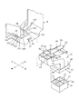
図3を参照し、中継樋31の構成を説明する。中継樋31は、外側部材63と内側部材64とが組み合わされて形成される。外側部材63は、上部、右端、下部が開放された構造であり、前後に対向する前壁201の右端下部202と後壁203の右端下部204とを互いに近づく方向に撓ませた状態で、結合筒体61の筒孔205に通すことにより、結合筒体61を外側部材63の外側に位置させ、そして、前壁201と後壁203との間に上方から内側部材64を嵌め込んで、止ねじ206が外側部材63の前壁201と後壁203とに形成された貫通孔207に外側から挿入され、内側部材64に形成された取付孔208に締結される。これにより、球出口部74の外側に結合筒体61が上下方向に移動可能に設けられた中継樋31が形成される。結合筒体61は、上ストッパ59と中継樋31の下端に設けられた下ストッパ60とが衝突することによって、中継樋31より下方に抜けないように取付けられる。即ち、外側部材63が環状の結合筒体61の筒孔205に通された後に、内側部材64が外側部材63内に嵌め込まれ、外側部材63と内側部材64とが止ねじ206で結合されて中継樋31が形成されることによって、結合筒体61が中継樋31の下端部の外側に上下移動可能に取り付けられる。つまり、筒状の結合筒体61を、中継樋31の下端部の外側に上下移動可能に、かつ、中継樋31の下端部から脱落しないように容易に組み付けることができる。   With reference to FIG. 3, the structure of the relay rod 31 is demonstrated. The relay rod 31 is formed by combining an outer member 63 and an inner member 64. The outer member 63 has a structure in which an upper portion, a right end, and a lower portion are open, and is coupled in a state where the right end lower portion 202 of the front wall 201 and the right end lower portion 204 of the rear wall 203 facing each other are bent in a direction approaching each other. By passing through the cylindrical hole 205 of the cylindrical body 61, the coupling cylindrical body 61 is positioned outside the outer member 63, and the inner member 64 is fitted between the front wall 201 and the rear wall 203 from above to stop A screw 206 is inserted from the outside into a through hole 207 formed in the front wall 201 and the rear wall 203 of the outer member 63 and fastened to a mounting hole 208 formed in the inner member 64. As a result, the relay rod 31 is formed on the outside of the ball outlet portion 74 so that the coupling cylinder 61 is movable in the vertical direction. The coupling cylinder 61 is attached so that it does not come out below the relay rod 31 when the upper stopper 59 and the lower stopper 60 provided at the lower end of the relay rod 31 collide with each other. That is, after the outer member 63 is passed through the cylindrical hole 205 of the annular coupling cylinder 61, the inner member 64 is fitted into the outer member 63, and the outer member 63 and the inner member 64 are coupled by the set screw 206. By forming the relay rod 31, the coupling cylinder 61 is attached to the outside of the lower end portion of the relay rod 31 so as to be vertically movable. That is, the cylindrical coupling cylinder 61 can be assembled to the outside of the lower end portion of the relay rod 31 so as to be movable up and down so as not to fall off from the lower end portion of the relay rod 31.

図7に示すように、縦樋30は、遊技主体収納構造体29の裏面に取り付けられる。縦樋30は、中継樋31の賞球通路32と繋がる賞球通路42、中継樋31の抜球通路33と繋がる抜球通路46を備える。   As shown in FIG. 7, the downboard 30 is attached to the back surface of the game main body storage structure 29. The vertical rod 30 includes a prize ball passage 42 connected to the prize ball passage 32 of the relay rod 31 and a ball extraction passage 46 connected to the ball extraction passage 33 of the relay rod 31.

図4を参照し、パチンコ機の遊技機枠について説明する。パチンコ機の遊技機枠173は、固定枠174の前側に可動枠175を開閉可能に備える。固定枠174は、遊技機設置構造体に取り付けられる外枠とも呼ばれる。可動枠175は、遊技主体としての図外の遊技盤や制御装置など遊技に必要な部品を取り付ける前枠とも呼ばれ、上記遊技主体収納構造体29を備える。可動枠175は、左側に位置するヒンジ176を中心とし、固定枠174の前側で前側に開かれかつ後側に閉じられるように、片開き可能である。可動枠175には、開口部177が、前後方向の貫通孔として設けられる。開口部177は、遊技盤の裏面に取り付けられた図外の球案内構造体や制御装置などの裏側部品を可動枠175の前側から裏側に貫通させるか、または、遊技盤の前面に取り付けられたガイドレールや入賞部品などの前側部品を可動枠175の裏側から前側に貫通させるためのものである。   The gaming machine frame of the pachinko machine will be described with reference to FIG. The gaming machine frame 173 of the pachinko machine includes a movable frame 175 that can be opened and closed on the front side of the fixed frame 174. The fixed frame 174 is also referred to as an outer frame attached to the gaming machine installation structure. The movable frame 175 is also called a front frame for attaching parts necessary for a game such as a game board and a control device (not shown) as a game main body, and includes the game main body storage structure 29. The movable frame 175 can be opened halfway around the hinge 176 located on the left side so that the movable frame 175 can be opened frontward and closed rearward of the fixed frame 174. The movable frame 175 is provided with an opening 177 as a through hole in the front-rear direction. The opening 177 is inserted through a back side part such as a ball guide structure or a control device (not shown) attached to the back side of the game board from the front side to the back side of the movable frame 175, or attached to the front side of the game board. The front parts such as guide rails and winning parts are made to penetrate from the back side of the movable frame 175 to the front side.

図4及び図7を参照しながら、パチンコ機の球払出装置1の組み立てについて説明する。まず、タンク構造体2及び縦樋30が遊技主体収納構造体29の裏面に取り付けられる。タンク構造体2は、開口部177の上部に位置するように、遊技主体収納構造体29の裏面に、ねじのような固着具で、遊技主体収納構造体29の裏側から取り付けられる。縦樋30は、開口部177の右側に位置するように、遊技主体収納構造体29の裏面に、ねじのような固着具で、遊技主体収納構造体29の裏側から取り付けられる。次に、払出機構3が止ねじ7でタンク構造体2の右端に取り付けられる。そして、中継樋31が払出機構3の下端と縦樋30の上端とを繋ぐように取り付けられる。すなわち、結合筒体61が上方に移動された状態で、遊技機枠173の右方から中継樋31の上係合部34が払出機構3の下係合部37に係合された後に、結合筒体61が下方に移動されることによって、上ストッパ59と下ストッパ60とが係合されて結合筒体61が縦樋30の上部の外周囲を囲むように位置される。つまり、中継樋31の球出口部74と縦樋30の球入口部75とを上下方向で向かい合わせた状態において、結合筒体61を下方に落とすことによって、結合筒体61が中継樋31の球出口部74と縦樋30の球入口部75とに渡ってこれらの外側とを被覆し、上ストッパ59と下ストッパ60とが互いに衝突したことによって、結合筒体61がそれ以上下方に移動しないで球出口部74と球入口部75とを結合する。以上により、図4に示すように、パチンコ機の裏面に球払出装置1が取り付けられる。中継樋31を取り外す場合は、結合筒体61が上方に移動され弾性片58が下方に撓ませられた状態で、中継樋31を右方に引き抜くことで容易に外れる。   The assembly of the ball dispensing device 1 of the pachinko machine will be described with reference to FIGS. 4 and 7. First, the tank structure 2 and the vertical rod 30 are attached to the back surface of the game main body storage structure 29. The tank structure 2 is attached to the back surface of the game main body storage structure 29 from the back side of the game main body storage structure 29 with a fixing tool such as a screw so as to be positioned above the opening 177. The vertical rod 30 is attached to the back surface of the game main body storage structure 29 from the back side of the game main body storage structure 29 with a fixing tool such as a screw so as to be positioned on the right side of the opening 177. Next, the payout mechanism 3 is attached to the right end of the tank structure 2 with a set screw 7. The relay rod 31 is attached so as to connect the lower end of the payout mechanism 3 and the upper end of the vertical rod 30. That is, after the coupling cylinder 61 is moved upward, the upper engagement portion 34 of the relay rod 31 is engaged with the lower engagement portion 37 of the payout mechanism 3 from the right side of the gaming machine frame 173 and then coupled. By moving the cylinder 61 downward, the upper stopper 59 and the lower stopper 60 are engaged, and the coupling cylinder 61 is positioned so as to surround the outer periphery of the upper part of the vertical rod 30. In other words, in a state where the ball outlet portion 74 of the relay rod 31 and the ball inlet portion 75 of the vertical rod 30 face each other in the vertical direction, the coupling cylinder 61 is dropped downward, so that the coupling cylinder 61 is attached to the relay rod 31. The outer cylinder 74 covers the outer side of the ball outlet portion 74 and the ball inlet portion 75 of the vertical rod 30, and the upper stopper 59 and the lower stopper 60 collide with each other. Instead, the ball outlet portion 74 and the ball inlet portion 75 are coupled. As described above, as shown in FIG. 4, the ball dispensing device 1 is attached to the back surface of the pachinko machine. When the relay rod 31 is removed, it can be easily removed by pulling the relay rod 31 to the right in a state where the coupling cylinder 61 is moved upward and the elastic piece 58 is bent downward.

球払出装置1では、球が、タンク構造体2、払出機構3の賞球通路153、中継樋31の賞球通路32、縦樋30の賞球通路42を経由して、受樋181で受け止められる。受樋181は、開口部177の下部に位置するように、遊技主体収納構造体29の裏面に、ねじのような固着具で、遊技主体収納構造体29の裏側から取り付けられる。受樋181で受け止められた球は、受樋181から図外の皿構造体の受皿部に排出される。皿構造体は、遊技主体収納構造体29の前面に取り付けられる。皿構造体の受皿部は、遊技者が遊技に使用する球を入れる部分である。そして、球が受皿部に存在する状態において、遊技者が皿構造体の前面に設けられた発射操作機構を操作すると、皿構造体の裏側に位置するように、遊技主体収納構造体29の前面に取り付けられた発射機構が受皿部から供給された球を1個ずつ遊技盤のガイドレールで囲まれた内側の遊技領域に向けて発射する。球が、タンク構造体2、払出機構3の抜球通路100、中継樋31の抜球通路33、縦樋30の抜球通路46を経由して、遊技機設置構造体の回収機構に排出される。回収機構に排出された球は、遊技機設置構造体の補給機構に戻される。   In the ball dispensing device 1, the ball is received by the receiving rod 181 through the tank structure 2, the prize ball passage 153 of the dispensing mechanism 3, the prize ball passage 32 of the relay rod 31, and the prize ball passage 42 of the vertical rod 30. It is done. The receiving rod 181 is attached to the back surface of the game main body storage structure 29 from the back side of the game main body storage structure 29 with a fixing tool such as a screw so as to be positioned below the opening 177. The ball received by the receiving rod 181 is discharged from the receiving rod 181 to the receiving tray portion of the dish structure not shown. The dish structure is attached to the front surface of the game main body storage structure 29. The saucer part of the dish structure is a part into which a player uses a ball used for the game. Then, when the player operates the firing operation mechanism provided on the front surface of the dish structure in a state where the ball is present in the tray portion, the front surface of the game main body storage structure 29 is positioned so as to be located on the back side of the dish structure. The launching mechanism attached to the launcher launches the balls supplied from the saucer one by one toward the inner game area surrounded by the guide rails of the game board. The ball is discharged to the collection mechanism of the gaming machine installation structure via the tank structure 2, the ball extraction passage 100 of the payout mechanism 3, the ball extraction passage 33 of the relay rod 31, and the ball extraction passage 46 of the vertical rod 30. The The balls discharged to the collection mechanism are returned to the supply mechanism of the gaming machine installation structure.

最良の形態2
図5乃至図7は、最良の形態2を示す。図5は、球払出装置の断面を示す。図6は、球払出装置の機構躯体の下係合部及び中継樋の上係合部の構成を示す。図7は球払出装置を分解して示す。図7に示すように、最良の形態2による球払出装置1の払出機構3は、払出構造体4の前後側において払出軸82に沿った方向と上下に直交する方向に弁軸123を回転中心として互いに近接し合う方向に回転する相対峙する切替弁121;122を備え、下部の前後方向に、抜球通路100の球出口、賞球通路153の球出口、賞球通路153の球出口、抜球通路100の球出口という順番に4つの球通路の球出口が一直線状に配置された構成である。そして、中継樋31は、上部の前後方向に、抜球通路33の球入口、賞球通路32の球入口、賞球通路32の球入口、抜球通路33の球入口という順番に4つの球通路の球入口が一直線状に配置され、下部の前後左右方向には、左右に隣り合うように設けられた一対の抜球通路33の球出口と賞球通路32の球出口とが前後に隣り合うように2組設けられた構成である。したがって、最良の形態2の球払出装置1によれば、最良の形態1の球払出装置1により得られる効果以外に、払出機構3の4つの球出口が前後に一直線状に配置された構成のために、払出機構3の左右方向の幅長が短くなるため、払出機構3の右方の部品配置スペースを広くできるという効果が得られる。
Best form 2
5 to 7 show the best mode 2. FIG. FIG. 5 shows a cross section of the ball dispensing device. FIG. 6 shows the configuration of the lower engaging portion of the mechanism housing and the upper engaging portion of the relay rod of the ball dispensing device. FIG. 7 is an exploded view of the ball dispensing device. As shown in FIG. 7, the payout mechanism 3 of the ball payout device 1 according to the best mode 2 has the valve shaft 123 as the center of rotation in a direction perpendicular to the direction along the payout shaft 82 on the front and rear sides of the payout structure 4. Switching valves 121; 122 that rotate in directions close to each other, and in the front-back direction of the lower part, a ball outlet of the ball extraction passage 100, a ball outlet of the prize ball passage 153, a ball outlet of the prize ball passage 153, The ball outlets of the four ball passages are arranged in a straight line in the order of the ball outlets of the extraction passage 100. The relay rod 31 has four balls in the order of the ball entrance of the ball passage 33, the ball entrance of the prize ball passage 32, the ball entrance of the prize ball passage 32, and the ball entrance of the ball passage 33 in the front-rear direction of the upper part. The ball entrances of the passages are arranged in a straight line, and in the front, rear, left, and right directions, a pair of ball exits 33 and a ball exit of the prize ball passage 32 are adjacent to each other in the front-rear direction. Two sets are provided to fit. Therefore, according to the ball dispensing device 1 of the best mode 2, in addition to the effects obtained by the ball dispensing device 1 of the best mode 1, the four ball outlets of the dispensing mechanism 3 are arranged in a straight line at the front and rear. For this reason, the width in the left-right direction of the payout mechanism 3 is shortened, so that an effect of widening the right part arrangement space of the payout mechanism 3 can be obtained.

図6を参照し、最良の形態2の機構躯体6の下部及び中継樋31の構造を説明する。機構躯体6の下部には、賞球通路153及び抜球通路100の球出口となる開口部101及び中継樋31の取付用の下係合部37を備える。下係合部37は、係合溝38;39、係合突起400を備える。係合溝38;39は、開口部101の前後で相対峙する両方の開口縁102に設けられた突出部103により形成される。突出部103は、開口縁102より下方に延長する縦片104と縦片104の下端より延長する横片105とにより形成される。係合溝38の横片105と係合溝39の横片105とは互いに近づく方向に延長する。係合突起400は開口部101の右縁106よりも右側の下面から下方に突出する。   The structure of the lower part of the mechanism housing 6 and the relay housing 31 of the best mode 2 will be described with reference to FIG. The lower part of the mechanism housing 6 includes an opening 101 serving as a ball outlet of the winning ball passage 153 and the ball extraction passage 100 and a lower engagement portion 37 for attaching the relay rod 31. The lower engagement portion 37 includes engagement grooves 38 and 39 and an engagement protrusion 400. The engaging grooves 38; 39 are formed by protrusions 103 provided on both opening edges 102 that face each other before and after the opening 101. The protrusion 103 is formed by a vertical piece 104 that extends downward from the opening edge 102 and a horizontal piece 105 that extends from the lower end of the vertical piece 104. The lateral piece 105 of the engaging groove 38 and the lateral piece 105 of the engaging groove 39 extend in a direction approaching each other. The engagement protrusion 400 protrudes downward from the lower surface on the right side of the right edge 106 of the opening 101.

中継樋31は、賞球通路153と繋がる賞球通路32、抜球通路100と繋がる抜球通路33、上係合部34、下係合部35を備える。上係合部34は、係合片47;48、係合突起490を備える。係合片47は、挿入片52、張出片530を備える。挿入片52は、抜球通路33の入口の後縁より後方に突出して係合溝38内に挿入される。張出片530は、挿入片52の右端に設けられて挿入片52より下方に突出して係合溝38の縦片104に係止する。係合片48は、挿入片54、張出片550を備える。挿入片54は、抜球通路33の入口の前縁より前方に突出して係合溝39内に挿入される。張出片550は、挿入片54の右端に設けられて挿入片54より下方に突出して係合溝39の縦片104に係止する。係合突起490は、抜球通路33;33の上壁が切欠かれて左右に延長するよう板ばね片580の左端部が板ばね片580の前後縁に渡って上方に隆起されて形成された突起により形成され、板ばね片580の弾性により係合突起400を右方から乗り越えて係合突起400の左面401に係止する。よって、上係合部と下係合部とが係合されることによって機構躯体6と中継樋31とが互いに連結され、下係合部と縦樋の上部とが係合されることによって中継樋と縦樋とが互いに連結される。中継樋31を取り外す場合は、結合筒体61が上方に移動され板ばね片580が下方に撓ませられた状態で、中継樋31を右方に引き抜くことで容易に外れる。   The relay bowl 31 includes a prize ball passage 32 connected to the prize ball passage 153, a ball extraction passage 33 connected to the ball extraction passage 100, an upper engagement portion 34, and a lower engagement portion 35. The upper engagement portion 34 includes engagement pieces 47; 48 and an engagement protrusion 490. The engagement piece 47 includes an insertion piece 52 and an overhanging piece 530. The insertion piece 52 protrudes rearward from the rear edge of the entrance of the extraction passage 33 and is inserted into the engagement groove 38. The overhanging piece 530 is provided at the right end of the insertion piece 52, protrudes downward from the insertion piece 52, and engages with the vertical piece 104 of the engagement groove 38. The engagement piece 48 includes an insertion piece 54 and an overhanging piece 550. The insertion piece 54 protrudes forward from the front edge of the entrance of the extraction passage 33 and is inserted into the engagement groove 39. The overhanging piece 550 is provided at the right end of the insertion piece 54, protrudes downward from the insertion piece 54, and engages with the vertical piece 104 of the engagement groove 39. The engagement protrusion 490 is formed by projecting the left end of the leaf spring piece 580 upward over the front and rear edges of the leaf spring piece 580 so that the upper wall of the ball passage 33; The protrusion is formed by a protrusion, and the engagement protrusion 400 is overcome from the right by the elasticity of the leaf spring piece 580 and is locked to the left surface 401 of the engagement protrusion 400. Therefore, the mechanism housing 6 and the relay rod 31 are connected to each other by engaging the upper engagement portion and the lower engagement portion, and the relay is performed by engaging the lower engagement portion and the upper portion of the vertical rod. The kite and the vertical kite are connected to each other. When the relay rod 31 is removed, it can be easily removed by pulling the relay rod 31 to the right in a state where the coupling cylinder 61 is moved upward and the leaf spring piece 580 is bent downward.

最良の形態1と同じように、払出機構3が止ねじ7でタンク構造体2の右端に取り付けられ、止ねじ7が機構取付部9に締結された状態において基盤150と右側壁99とが互いに接触する。そして、中継樋31が払出機構3の下端と縦樋30の上端とを繋ぐように取り付けられる。すなわち、結合筒体61が上方に移動された状態で、遊技機枠173の右方から中継樋31の上係合部34が払出機構3の下係合部37に係合された後に、結合筒体61が下方に移動されることによって、上ストッパ59と下ストッパ60とが係合されて結合筒体61が縦樋30の上部の外周囲を囲むように位置される(図5参照)。最良の形態2によれば、機構躯体6の下係合部37と中継樋31の上係合部34とによる係合結合によって、中継樋31が払出機構3における機構躯体6の下部の正しい位置に正確に取り付けられ、板ばね片580が下方に移動して係合突起490と係合突起400との係合係止が解除されないかぎり、中継樋31が機構躯体6より脱落することもない。また、下係合部37の係合突起400と上係合部34の係合突起490とが互いに係合する凹凸により形成され、上係合部34が、板ばね片580と板ばね片580による付勢によって係合突起400に係合する係合突起490とを備え、係合突起490が、板ばね片580による付勢によって下係合部37の係合突起400に係合する形態に形成されたので、板ばね片580が下方に移動された状態で挿入片52;54が係合溝38;39内に挿入されることで、係合突起490が係合突起400に容易に係合されるので、取付操作が容易となる。   As with the best mode 1, the base 150 and the right side wall 99 are connected to each other in a state in which the dispensing mechanism 3 is attached to the right end of the tank structure 2 with a set screw 7 and the set screw 7 is fastened to the mechanism attaching portion 9. Contact. The relay rod 31 is attached so as to connect the lower end of the payout mechanism 3 and the upper end of the vertical rod 30. That is, after the coupling cylinder 61 is moved upward, the upper engagement portion 34 of the relay rod 31 is engaged with the lower engagement portion 37 of the payout mechanism 3 from the right side of the gaming machine frame 173 and then coupled. When the cylinder 61 is moved downward, the upper stopper 59 and the lower stopper 60 are engaged with each other, and the coupling cylinder 61 is positioned so as to surround the outer periphery of the upper portion of the vertical rod 30 (see FIG. 5). . According to the best mode 2, the relay rod 31 is correctly positioned at the lower portion of the mechanism housing 6 in the payout mechanism 3 by the engagement coupling between the lower engagement portion 37 of the mechanism housing 6 and the upper engagement portion 34 of the relay housing 31. The relay rod 31 does not fall off from the mechanism housing 6 unless the leaf spring piece 580 is moved downward and the engagement locking between the engagement protrusion 490 and the engagement protrusion 400 is released. Further, the engaging protrusion 400 of the lower engaging portion 37 and the engaging protrusion 490 of the upper engaging portion 34 are formed by unevenness, and the upper engaging portion 34 has the leaf spring piece 580 and the leaf spring piece 580. The engagement protrusion 490 is engaged with the engagement protrusion 400 by the urging force of the engagement member 400, and the engagement protrusion 490 is engaged with the engagement protrusion 400 of the lower engagement portion 37 by the urging force of the leaf spring piece 580. Thus, the engagement protrusion 490 is easily engaged with the engagement protrusion 400 by inserting the insertion piece 52; 54 into the engagement groove 38; 39 with the leaf spring piece 580 moved downward. As a result, the mounting operation becomes easy.

最良の形態3
図7及び図8に示すように、タンク構造体2と最良の形態1;2の2種類の払出機構3;3との連結を可能とする構造として、タンク構造体2が、右側壁99、機構取付部9、上開口21、下開口22を備え、払出機構3;3が共に筐体取付部8を備える。縦樋30と最良の形態1;2の2種類の中継樋31;31との連結を可能とする構造として、中継樋31;31が共に下係合部35を備え、縦樋30が下係合部35と係合する上部形状を備える。したがって、遊技主体収納構造体29の裏面に取り付けられたタンク構造体2及び縦樋30に、最良の形態1の払出機構3及び中継樋31か最良の形態2の払出機構3及び中継樋31かを選択して取り付けることが可能となり、2種類の球払出装置1;1を形成することが可能となる。つまり、パチンコ機の機種が異なると遊技主体収納構造体29の裏面に搭載された部品の配置なども異なる。そこで、遊技主体収納構造体29の裏面に搭載された部品と衝突したり接近しすぎたりといった干渉を避けるために払出機構3及び中継樋31を選択して取り付けることができるようになる。
Best form 3
As shown in FIGS. 7 and 8, the tank structure 2 includes a right side wall 99, as a structure that enables connection between the tank structure 2 and the two types of delivery mechanisms 3; 3 in the best mode 1; 2. A mechanism mounting portion 9, an upper opening 21, and a lower opening 22 are provided, and both the payout mechanisms 3; 3 include a housing mounting portion 8. As a structure that enables connection between the vertical rod 30 and the two types of relay rods 31; 31 in the best mode 1; 2, the relay rods 31; 31 are each provided with a lower engaging portion 35, and the vertical rod 30 is a lower link. An upper shape that engages with the joint portion 35 is provided. Therefore, the tank structure 2 and the vertical rod 30 attached to the back surface of the game main body storage structure 29 are connected to the payout mechanism 3 and relay rod 31 of the best mode 1 or the payout mechanism 3 and relay rod 31 of the best mode 2. Can be selected and attached, and two types of ball dispensing devices 1; 1 can be formed. That is, when the model of the pachinko machine is different, the arrangement of components mounted on the back surface of the game main body storage structure 29 is different. Therefore, the payout mechanism 3 and the relay basket 31 can be selected and attached in order to avoid interference such as collision with a part mounted on the back surface of the game main body storage structure 29 or excessive approach.

つまり、最良の形態2の払出機構3の賞球通路153及び抜球通路100の球出口は前後に一直線状に4列に形成され、中継樋31の賞球通路32及び抜球通路33の球入口は前後に一直線状に4列に形成され、中継樋31の賞球通路32及び抜球通路33の球出口は共に前後2列左右2列に形成される。したがって、払出機構3の左右幅が短くなるので、払出機構3に設置場所の右側に大きな部品が搭載されるような機種の場合に、最良の形態2の払出機構3及び中継樋31を取り付けることによって、払出機構3と部品との干渉を避けることができる。また、最良の形態2の中継樋31の賞球通路32及び抜球通路33の球入口から下方に延長する通路の上下方向の長さが短いので、中継樋31の球入口の下方に大きな部品が搭載されているような機種の場合に、最良の形態2の払出機構3及び中継樋31を取り付けることによって、払出機構3と部品との干渉を避けることができる。   That is, the ball outlets of the prize ball passage 153 and the ball extraction passage 100 of the payout mechanism 3 of the best mode 2 are formed in four lines in a straight line in the front and rear, and the balls of the prize ball passage 32 and the ball extraction passage 33 of the relay rod 31 are formed. The entrances are formed in four lines in a straight line in the front-rear direction, and the ball outlets 32 of the relay ball 31 and the ball outlets 33 are both formed in the front-rear two-row left-right two-row. Therefore, since the left-right width of the payout mechanism 3 is shortened, the payout mechanism 3 and the relay rod 31 of the best mode 2 are attached to a model in which a large part is mounted on the payout mechanism 3 on the right side of the installation location. Thus, interference between the payout mechanism 3 and the parts can be avoided. Further, since the length of the passage extending downward from the ball entrance of the winning ball passage 32 and the ball extraction passage 33 of the relay rod 31 of the best mode 2 is short, a large part below the ball entrance of the relay rod 31 is large. In the case of a model in which is mounted, the interference between the payout mechanism 3 and parts can be avoided by attaching the payout mechanism 3 and the relay rod 31 of the best mode 2.

また、最良の形態1の払出機構3の賞球通路153及び抜球通路100の球出口及び中継樋31の賞球通路32及び抜球通路33の球入口は共に前後2列左右2列に形成され、払出機構3及び中継樋31の前後幅が短くなるので、払出機構3に設置場所の前側又は後側に大きな部品が搭載されているような機種の場合に、最良の形態2の払出機構3及び中継樋31を取り付けることによって、払出機構3及び中継樋31と部品との干渉を避けることができる。すなわち、タンク構造体2が複数の払出機構3との連結を可能とする払出連結部として、右側壁99、機構取付部9、上開口21、下開口22を備え、縦樋30が複数の中継樋31との連結を可能とする中継連結部として、下係合部35と係合する形状に形成された上部の球入口部75の外周部110を備えたので、遊技主体収納構造体29の裏面に搭載された部品との干渉を避けるように払出機構3や中継樋31を取り付けることができるようになる。尚、止ねじ7が最良の形態1;2の2種類の払出機構3;3における機構取付部9に締結された状態において基盤150と右側壁99とが互いに接触する。   Further, the ball outlets of the award ball passage 153 and the ball extraction passage 100 of the payout mechanism 3 of the best mode 1 and the ball inlets of the prize ball passage 32 and the ball extraction passage 33 of the relay rod 31 are formed in two rows on the front and rear and two rows on the left and right sides. Since the front and rear widths of the payout mechanism 3 and the relay rod 31 are shortened, the payout mechanism of the best mode 2 is used in the case of a model in which large parts are mounted on the payout mechanism 3 on the front side or the rear side of the installation place. By attaching 3 and the relay rod 31, it is possible to avoid interference between the payout mechanism 3 and the relay rod 31 and parts. That is, the tank structure 2 includes a right side wall 99, a mechanism attachment portion 9, an upper opening 21, and a lower opening 22 as a dispensing connection portion that enables the tank structure 2 to be coupled to a plurality of dispensing mechanisms 3, and the vertical rod 30 has a plurality of relays Since the outer peripheral portion 110 of the upper ball inlet portion 75 formed in a shape that engages with the lower engaging portion 35 is provided as a relay connecting portion that enables connection with the basket 31, the game main body storage structure 29 The payout mechanism 3 and the relay rod 31 can be attached so as to avoid interference with components mounted on the back surface. The base 150 and the right side wall 99 are in contact with each other when the set screw 7 is fastened to the mechanism mounting portion 9 in the two types of payout mechanisms 3;

本発明の球払出装置は、パチンコ機の他、球を遊技媒体としたスロットマシンにも適用できる。   The ball payout device of the present invention can be applied to a slot machine using a ball as a game medium in addition to a pachinko machine.

球払出装置の断面図(最良の形態1)。Sectional drawing of a ball paying apparatus (best form 1). 球払出装置の機構躯体の下係合部及び中継樋の上係合部の構成を示す分解斜視図(最良の形態1)。The disassembled perspective view which shows the structure of the lower engaging part of the mechanism housing of a ball dispensing apparatus, and the upper engaging part of a relay rod (the best form 1). 中継樋の分解斜視図(最良の形態1)。FIG. 3 is an exploded perspective view of the relay rod (best mode 1). 球払出装置を備えたパチンコ遊技機を裏側から見た図(最良の形態1)。The figure which looked at the pachinko game machine provided with the ball dispensing device from the back side (best mode 1). 球払出装置の断面図(最良の形態2)。Sectional drawing (best form 2) of a ball dispensing apparatus. 球払出装置の機構躯体の下係合部及び中継樋の上係合部の構成を示す分解斜視図(最良の形態2)。The disassembled perspective view which shows the structure of the lower engaging part of the mechanism housing of a ball dispensing apparatus, and the upper engaging part of a relay rod (best form 2). 球払出装置の分解斜視図(最良の形態1;2;3)。Exploded perspective view of a ball dispensing device (best mode 1; 2; 3). 球払出装置のタンク構造体及び縦樋と複数の払出機構と複数の中継樋との連結可能な関係を示した模式図(最良の形態3)。FIG. 6 is a schematic diagram (best mode 3) showing a connectable relationship between a tank structure and a vertical rod of a ball dispensing device, a plurality of dispensing mechanisms, and a plurality of relay rods.

符号の説明Explanation of symbols

1 球払出装置、2 タンク構造体、3 払出機構、4 払出構造体、6 機構躯体、
9 機構取付部(払出連結部)、29 遊技主体収納構造体、30 縦樋、
31 中継樋、34 上係合部、35 下係合部、37 下係合部、40 係合孔、
49 係合突起、58 板ばね片、110 外周部(中継連結部)、173 遊技機枠。
1 ball dispensing device, 2 tank structure, 3 dispensing mechanism, 4 dispensing structure, 6 mechanism housing,
9 mechanism mounting portion (payout connecting portion), 29 game subject storage structure, 30 downspout,
31 relay rod, 34 upper engagement portion, 35 lower engagement portion, 37 lower engagement portion, 40 engagement hole,
49 engagement protrusion, 58 leaf spring piece, 110 outer peripheral part (relay connection part), 173 gaming machine frame.

Claims (1)

遊技機枠の遊技主体収納構造体の裏面に、補給される球を貯蔵するタンク構造体と、タンク構造体から球を1個ずつ分離しながら払い出す払出機構と、払出機構から払い出された球を下方に導く中継樋と、中継樋から排出される球を下方に排出する縦樋とを備えた遊技機の球払出装置において、
タンク構造体及び縦樋が遊技主体収納構造体に取り付けられ、
払出機構の払出構造体がタンク構造体の側方から内部に挿入され、止ねじが払出機構の機構躯体の外側から機構躯体を経由してタンク構造体に締結されることによって、機構躯体がタンク構造体の側面に取り付けられ、
機構躯体は下係合部を備え、機構躯体の下係合部は係合溝と係合孔とを備え、中継樋は上係合部と下係合部とを備え、中継樋の上係合部は、係合溝に挿入される挿入片と、板ばね片と、板ばね片に設けられて板ばね片による付勢によって係合孔に係合する係合突起とを備え、中継樋の挿入片が機構躯体の係合溝に挿入され、中継樋の係合突起が板ばね片による付勢によって機構躯体の係合孔に係合することにより、払出機構と中継樋とが互いに連結され、
中継樋の下係合部は、筒孔に中継樋が通されて中継樋の外側に上下移動可能に設けられた結合筒体と、中継樋における球出口部の下端縁の外周より外側に突出するように設けられた下ストッパと、結合筒体の上縁から内側に突出するよう設けられて下ストッパの上面に係止する上ストッパとを備え、結合筒体が下方に移動して上ストッパが下ストッパの上面に係止し、結合筒体が縦樋の上部の外周を上部の外周囲を囲むように位置されることによって、中継樋の球出口部と縦樋の球入口部とが上下方向で互いに連結されたことを特徴とする遊技機の球払出装置
A tank structure for storing balls to be replenished, a payout mechanism for paying off the balls one by one from the tank structure, and a payout mechanism paid out on the back surface of the gaming machine storage structure of the gaming machine frame In a ball payout device for a gaming machine comprising a relay rod for guiding the ball downward and a vertical rod for discharging the ball discharged from the relay rod downward,
The tank structure and downpipe are attached to the game main storage structure,
The delivery structure of the delivery mechanism is inserted into the tank structure from the side, and the set screw is fastened to the tank structure from outside the mechanism housing of the delivery mechanism via the mechanism chassis. Attached to the side of the structure,
The mechanism housing includes a lower engagement portion, the lower engagement portion of the mechanism housing includes an engagement groove and an engagement hole, and the relay rod includes an upper engagement portion and a lower engagement portion. The joint portion includes an insertion piece inserted into the engagement groove, a leaf spring piece, and an engagement protrusion provided on the leaf spring piece and engaged with the engagement hole by urging by the leaf spring piece. The insertion piece is inserted into the engagement groove of the mechanism housing, and the engagement protrusion of the relay rod is engaged with the engagement hole of the mechanism housing by the urging force of the leaf spring piece, so that the dispensing mechanism and the relay rod are connected to each other. And
The lower engagement portion of the relay rod protrudes outward from the outer periphery of the lower end edge of the ball outlet portion of the relay rod, and the coupling cylinder body that is provided so that the relay rod is passed through the tube hole and can be moved up and down outside the relay rod. A lower stopper provided so as to project and an upper stopper provided so as to protrude inward from the upper edge of the coupling cylinder and to be engaged with the upper surface of the lower stopper, and the coupling cylinder moves downward and the upper stopper Is engaged with the upper surface of the lower stopper, and the coupling cylinder is positioned so that the outer periphery of the upper part of the vertical fence surrounds the outer periphery of the upper part. A ball dispenser for a gaming machine, which is connected to each other in the vertical direction .
JP2005360675A 2005-12-14 2005-12-14 Ball dispenser for gaming machine Expired - Fee Related JP4986446B2 (en)

Priority Applications (1)

Application Number Priority Date Filing Date Title
JP2005360675A JP4986446B2 (en) 2005-12-14 2005-12-14 Ball dispenser for gaming machine

Applications Claiming Priority (1)

Application Number Priority Date Filing Date Title
JP2005360675A JP4986446B2 (en) 2005-12-14 2005-12-14 Ball dispenser for gaming machine

Publications (2)

Publication Number Publication Date
JP2007159852A JP2007159852A (en) 2007-06-28
JP4986446B2 true JP4986446B2 (en) 2012-07-25

Family

ID=38243420

Family Applications (1)

Application Number Title Priority Date Filing Date
JP2005360675A Expired - Fee Related JP4986446B2 (en) 2005-12-14 2005-12-14 Ball dispenser for gaming machine

Country Status (1)

Country Link
JP (1) JP4986446B2 (en)

Families Citing this family (1)

* Cited by examiner, † Cited by third party
Publication number Priority date Publication date Assignee Title
JP5229422B2 (en) * 2012-11-16 2013-07-03 奥村遊機株式会社 Pachinko machine

Family Cites Families (2)

* Cited by examiner, † Cited by third party
Publication number Priority date Publication date Assignee Title
JP2000189616A (en) * 1998-12-25 2000-07-11 Sanyo Bussan:Kk Game machine
JP2004321358A (en) * 2003-04-23 2004-11-18 Heiwa Corp Pachinko game machine

Also Published As

Publication number Publication date
JP2007159852A (en) 2007-06-28

Similar Documents

Publication Publication Date Title
JP4457044B2 (en) Game machine
JP4986446B2 (en) Ball dispenser for gaming machine
JP4493517B2 (en) Game machine
JP2007175316A (en) Ball putout device of game machine
JP4878094B2 (en) Game machine
JP5239489B2 (en) Pachinko machine
JP2009061061A (en) Game machine
JP4877720B2 (en) Ball dispenser for gaming machine
JP2009061060A (en) Game machine
JP2007135913A (en) Ball pay-out device of game machine
JP2007175327A (en) Ball putout structure of game machine
JP5125737B2 (en) Pachinko machine
JP4408056B2 (en) Game ball payout device and game machine
JP5692208B2 (en) Game machine
JP5125731B2 (en) Pachinko machine
JP5145928B2 (en) Game machine
JP5105934B2 (en) Ball dispenser for gaming machine
JP5024743B2 (en) Game machine
JP2007135993A (en) Ball pay-out device of game machine
JPH08164254A (en) Pachinko ball discharge device
JP2007236785A (en) Ball put-out device for game machine
JP4739854B2 (en) Ball dispenser for gaming machine
JP5141362B2 (en) Pachinko machine
JP5125738B2 (en) Pachinko machine
JP2001062105A (en) Ball pay out device of pachinko machine

Legal Events

Date Code Title Description
A621 Written request for application examination

Free format text: JAPANESE INTERMEDIATE CODE: A621

Effective date: 20080917

A977 Report on retrieval

Free format text: JAPANESE INTERMEDIATE CODE: A971007

Effective date: 20110228

A131 Notification of reasons for refusal

Free format text: JAPANESE INTERMEDIATE CODE: A131

Effective date: 20110405

A521 Written amendment

Free format text: JAPANESE INTERMEDIATE CODE: A523

Effective date: 20110601

TRDD Decision of grant or rejection written
A01 Written decision to grant a patent or to grant a registration (utility model)

Free format text: JAPANESE INTERMEDIATE CODE: A01

Effective date: 20120424

A01 Written decision to grant a patent or to grant a registration (utility model)

Free format text: JAPANESE INTERMEDIATE CODE: A01

A61 First payment of annual fees (during grant procedure)

Free format text: JAPANESE INTERMEDIATE CODE: A61

Effective date: 20120424

R150 Certificate of patent or registration of utility model

Ref document number: 4986446

Country of ref document: JP

Free format text: JAPANESE INTERMEDIATE CODE: R150

Free format text: JAPANESE INTERMEDIATE CODE: R150

FPAY Renewal fee payment (event date is renewal date of database)

Free format text: PAYMENT UNTIL: 20150511

Year of fee payment: 3

R250 Receipt of annual fees

Free format text: JAPANESE INTERMEDIATE CODE: R250

R250 Receipt of annual fees

Free format text: JAPANESE INTERMEDIATE CODE: R250

R250 Receipt of annual fees

Free format text: JAPANESE INTERMEDIATE CODE: R250

R250 Receipt of annual fees

Free format text: JAPANESE INTERMEDIATE CODE: R250

R250 Receipt of annual fees

Free format text: JAPANESE INTERMEDIATE CODE: R250

R250 Receipt of annual fees

Free format text: JAPANESE INTERMEDIATE CODE: R250

LAPS Cancellation because of no payment of annual fees