JP4986220B2 - Anode assembly for X-ray tube - Google Patents
Anode assembly for X-ray tube Download PDFInfo
- Publication number
- JP4986220B2 JP4986220B2 JP2006503802A JP2006503802A JP4986220B2 JP 4986220 B2 JP4986220 B2 JP 4986220B2 JP 2006503802 A JP2006503802 A JP 2006503802A JP 2006503802 A JP2006503802 A JP 2006503802A JP 4986220 B2 JP4986220 B2 JP 4986220B2
- Authority
- JP
- Japan
- Prior art keywords
- ray tube
- anode
- assembly
- tube assembly
- anode body
- Prior art date
- Legal status (The legal status is an assumption and is not a legal conclusion. Google has not performed a legal analysis and makes no representation as to the accuracy of the status listed.)
- Expired - Fee Related
Links
Images


Classifications
-
- H—ELECTRICITY
- H01—ELECTRIC ELEMENTS
- H01J—ELECTRIC DISCHARGE TUBES OR DISCHARGE LAMPS
- H01J35/00—X-ray tubes
- H01J35/32—Tubes wherein the X-rays are produced at or near the end of the tube or a part thereof which tube or part has a small cross-section to facilitate introduction into a small hole or cavity
-
- H—ELECTRICITY
- H01—ELECTRIC ELEMENTS
- H01J—ELECTRIC DISCHARGE TUBES OR DISCHARGE LAMPS
- H01J35/00—X-ray tubes
- H01J35/02—Details
- H01J35/04—Electrodes ; Mutual position thereof; Constructional adaptations therefor
- H01J35/08—Anodes; Anti cathodes
- H01J35/112—Non-rotating anodes
- H01J35/116—Transmissive anodes
-
- H—ELECTRICITY
- H01—ELECTRIC ELEMENTS
- H01J—ELECTRIC DISCHARGE TUBES OR DISCHARGE LAMPS
- H01J35/00—X-ray tubes
- H01J35/02—Details
- H01J35/16—Vessels; Containers; Shields associated therewith
- H01J35/18—Windows
- H01J35/186—Windows used as targets or X-ray converters
-
- H—ELECTRICITY
- H01—ELECTRIC ELEMENTS
- H01J—ELECTRIC DISCHARGE TUBES OR DISCHARGE LAMPS
- H01J2235/00—X-ray tubes
- H01J2235/08—Targets (anodes) and X-ray converters
- H01J2235/081—Target material
-
- H—ELECTRICITY
- H01—ELECTRIC ELEMENTS
- H01J—ELECTRIC DISCHARGE TUBES OR DISCHARGE LAMPS
- H01J2235/00—X-ray tubes
- H01J2235/16—Vessels
- H01J2235/163—Vessels shaped for a particular application
- H01J2235/164—Small cross-section, e.g. for entering in a body cavity
Description
本発明は、X線管のための、特に小型X線管のための陽極アセンブリーに関する。 The present invention relates to an anode assembly for an x-ray tube, in particular for a miniature x-ray tube.
X線管は特許第4,143,275号、特許第5,153,900号、特許第5,428,658号、特許第5,422,926号、特許第5,422,678号、特許第5,452,720号、特許第5,621,780号、再発行特許第34,421号、及び特許第6,319,188号に記載されており、これらのうちの幾つかは小型X線管に関する。本書で使われる小型X線管という用語は、特に、治療及び診断の医療目的に、また材料分析に有益な約10mm以下の直径のX線管を意味するように意図されている。 X-ray tube is patent 4,143,275, patent 5,153,900, patent 5,428,658, patent 5,422,926, patent 5,422,678, patent No. 5,452,720, Patent No. 5,621,780, Reissue Patent No. 34,421, and Patent No. 6,319,188, some of which are small X Regarding wire tubes. The term miniature X-ray tube as used herein is intended to mean an X-ray tube having a diameter of about 10 mm or less that is particularly useful for therapeutic and diagnostic medical purposes and for material analysis.
X線管の陽極は非常に重要な要素である。幾つかのアプリケーションでは、陽極は自分を通してX線を伝導して、X線をほぼ半径方向のみに放射するのではなくて該管からX線の放射に広い角度範囲を提供するべきである。 The anode of the X-ray tube is a very important element. In some applications, the anode should conduct X-rays through itself and provide a wide angular range for X-ray emission from the tube rather than emitting X-rays only in a substantially radial direction.
エックスオフトマイクロチューブ(Xoft microTube)の、上で引用された特許第6,319,188号は、陽極が概して平らであって、いろいろな実施態様で種々の角度範囲を通してX線放射が行われるようになっている小型X線管を記述している。 No. 6,319,188, cited above, of XofmicroTube, is such that the anode is generally flat and in various embodiments, X-ray radiation can occur through various angular ranges. A small X-ray tube is described.
本発明に何らかの関連のある他の特許は、特許第3,584,219号、特許第5,369,679号、特許第5,528,652号、特許第5,566,221号、再発行特許第35,383号、特許第6,095,966号、特許第6,134,300号及び国際公報WO097/07740を含む。 Other patents that are of some relevance to the present invention are: Patent 3,584,219, Patent 5,369,679, Patent 5,528,652, Patent 5,566,221, Reissue Patent No. 35,383, Patent No. 6,095,966, Patent No. 6,134,300 and International Publication No. WO 097/07740.
本発明の目的は、X線管の陽極アセンブリーの形状寸法及び構造を改善して、X線出力、シールの完全性或いは効率を犠牲にせずに広い放射角を提供すると共に管の耐用寿命のために必要なゲッターの効率的配置を提供することである。 It is an object of the present invention to improve the geometry and structure of the anode assembly of an X-ray tube to provide a wide radiation angle without sacrificing X-ray output, seal integrity or efficiency and for the useful life of the tube. It is to provide an efficient arrangement of getters needed.
本発明の好ましい実施態様では、X線管は、管フレームと、陰極アセンブリーと陽極アセンブリーとを有し、該陽極アセンブリーは、該管又はフレームと同軸の円錐形ターゲットを伴なう透過陽極を含む。陰極から電子ビームを受け取る該円錐形ターゲットの凹面側は該管の反対側端部に位置する。低原子番号(低−Z)、高熱伝導率の材料から形成されて、陽極はX線放射に関して高度に透過性であって、約0.5ないし5ミクロンの厚さの薄いターゲット膜を支持する。 In a preferred embodiment of the invention, the x-ray tube has a tube frame, a cathode assembly and an anode assembly, the anode assembly including a transmissive anode with a conical target coaxial with the tube or frame. . The concave side of the conical target that receives the electron beam from the cathode is located at the opposite end of the tube. Formed from a low atomic number (low-Z), high thermal conductivity material, the anode is highly transmissive for x-ray radiation and supports a thin target film about 0.5 to 5 microns thick .
一実施態様では、陽極は、陰極から最も遠い端部に頂点を有する完全な円錐体である。陽極ハウジングは外側が丸いか或いは弾丸形であり、該円錐体は陽極本体の内面として形成され、陽極本体が電気伝導性である場合には陽極自体を含む。好ましくは薄膜を含むターゲットは円錐面上にデポジットされる。陽極本体が電気伝導性でなければ、ターゲットは、伝導性材料でなければならず、陽極本体の外面に至る伝導路を持っていなければならない。 In one embodiment, the anode is a full cone with an apex at the end furthest from the cathode. The anode housing is round or bullet-shaped on the outside, and the cone is formed as the inner surface of the anode body and includes the anode itself if the anode body is electrically conductive. Preferably the target comprising the thin film is deposited on a conical surface. If the anode body is not electrically conductive, the target must be a conductive material and have a conductive path to the outer surface of the anode body.
ゲッターは陽極アセンブリーに収容されうるのが有利である。この目的のために、陽極アセンブリー内側の、該円錐体の基部に近い環状の拡大された領域又は凹部は円柱状のゲッターを包含することができる。該X線管の真空排気は、真空チャンバー内で該管の処理及び最終密封を行うことにより、或いは該管アセンブリー上の他の場所に位置する真空排気ポートによって行われうる。 The getter can advantageously be housed in an anode assembly. For this purpose, an annular enlarged region or recess inside the anode assembly close to the base of the cone can include a cylindrical getter. The X-ray tube can be evacuated by processing and final sealing the tube in a vacuum chamber, or by an evacuation port located elsewhere on the tube assembly.
陽極本体材料はベリリウム、ダイヤモンド、窒化アルミニウム、シリコン又は他の低−Zで高熱伝導性の材料であって良く、陽極薄膜ターゲット材料は白金、金、タングステンなどであって良い。更に、これらの材料は電子管両立性で密封可能である。低−Z本体と円錐形状とは、所望ならば、軸方向を含む、陽極のドーム型端部の周囲における実際上全方向へのX線の放射のための備えである。 The anode body material may be beryllium, diamond, aluminum nitride, silicon or other low-Z, high thermal conductivity material, and the anode thin film target material may be platinum, gold, tungsten, or the like. Furthermore, these materials can be sealed with electron tube compatibility. The low-Z body and conical shape provide provision for X-ray emission in practically all directions around the dome-shaped end of the anode, including the axial direction, if desired.
第2実施態様では陽極アセンブリーは円錐形内壁を有するが、その円錐の頂点があるところに、ゲッター材料のための空洞と真空排気ポートとに通じる軸穴を有する。この構成の1つの形では、陽極アセンブリーは基部側の端部に、該管フレームの内部空洞の残部への結合のための円柱状空洞を有し、陽極アセンブリーの円柱状空洞は先細端部に至る、すなわち、該円錐が陽極として役立つ。該円錐の穴から少し末端側に、ゲッター材料のための空洞又はチャンバーに通じる通路がある。この実施態様においてチュービュレーションが陽極本体の端部に相対して密封され、このチュービュレーション自体はゲッター・チャンバーの延長部を形成することができる。このチュービュレーションの末端部は、真空排気後に挟みつぶされる。 In the second embodiment, the anode assembly has a conical inner wall, but at the apex of the cone, has an axial hole that leads to a cavity for the getter material and an evacuation port. In one form of this configuration, the anode assembly has a cylindrical cavity at the proximal end for coupling to the remainder of the inner cavity of the tube frame, the cylindrical cavity of the anode assembly at the tapered end. That is, the cone serves as the anode. A little distal from the conical hole is a passage leading to a cavity or chamber for the getter material. In this embodiment, the tubulation is sealed relative to the end of the anode body, which itself can form an extension of the getter chamber. The end of this tubulation is pinched after evacuation.
第3の実施態様では、円錐形内面を有する陽極と管フレームとは,X線管製造プロセス中に陽極とフレームとを結合させる必要をなくする一体のアセンブリーとして形成される。この一体化された陽極及びフレームの構造は、ゲッター材料のための内部空洞を包含することができ、或いは、ゲッター・チャンバーの延長部を形成するチュービュレーションを有する真空排気ポートを持つことができる。この実施態様のX線管の真空排気は、真空チャンバー内で該管を組み立てることにより、或いは該アセンブリーに位置する排気ポートを通して、実行されうる。 In a third embodiment, the anode having a conical inner surface and the tube frame are formed as a unitary assembly that eliminates the need to join the anode and frame during the x-ray tube manufacturing process. This integrated anode and frame structure can include an internal cavity for the getter material, or it can have an evacuation port with a tubulation that forms an extension of the getter chamber. . The evacuation of the X-ray tube of this embodiment can be performed by assembling the tube in a vacuum chamber or through an exhaust port located in the assembly.
第4の実施態様では、排気を提供するためのチュービュレーション・アセンブリーは、一端では管フレームと、反対側の端では円錐形内面を有する陽極と互いに密封され、これにより完成したX線管空洞を提供する。このチュービュレーション・アセンブリーは、ゲッター材料のための内部空洞を提供することもできる。この実施態様のX線管の真空排気は、チュービュレーション・アセンブリーに配置された排気ポートを通して実行されうる。 In a fourth embodiment, a tubulation assembly for providing exhaust is sealed to one another by a tube frame at one end and an anode having a conical inner surface at the opposite end, thereby completing a completed X-ray tube cavity. I will provide a. This tubulation assembly can also provide an internal cavity for the getter material. The evacuation of the X-ray tube of this embodiment can be performed through an evacuation port located in the tubulation assembly.
ゲッターが効率的に包含されていて陽極構造が該アセンブリーの末端からの殆ど全方向へのX線放射を許すX線管の、特に小型X線管の効率的陽極構造を提供することが本発明の主要な目的のうちの1つである。本発明のこれらの、及びその他の目的、利点及び特徴は、好ましい実施態様についての以下の記述を図面と共に検討することから明らかとなるであろう。 It is an object of the present invention to provide an efficient anode structure of an X-ray tube, particularly a miniature X-ray tube, in which a getter is efficiently included and the anode structure allows X-ray emission in almost all directions from the end of the assembly. Is one of the main purposes. These and other objects, advantages and features of the present invention will become apparent from a consideration of the following description of preferred embodiments in conjunction with the drawings.
図面において、図1は、本発明による陽極端部12を含むX線管アセンブリー10の一部分を示す。陽極アセンブリー12は、この実施態様では、低−Z、高熱伝導率材料を含む陽極本体16により形成された弾丸状、ドーム状又は概して半球形又は丸い末端部14を有する。例は、ベリリウム、酸化ベリリウム、窒化ホウ素、窒化アルミニウム、窒化ケイ素、ダイヤモンド又は酸化アルミニウムである。他の望ましい材料は、アルミニウム或いはベリリウムの合金、或いはその組み合わせである。この様な材料は、X線放射に対しては非常に僅かな障壁となるだけであり、一方、陽極アセンブリー及びX線管から熱を効率よく伝導除去することを可能にする。本体材料はX線に対して殆ど透明である。
In the drawings, FIG. 1 shows a portion of an
この陽極本体16は、円錐形又は本質的に円錐形で、電子により衝撃が与えられたときにX線を生じさせるための薄膜ターゲット20でコーティングされている内面18を有する。円錐形状は、半球形状と比べると、電子ビーム22の全ての部分が陽極表面に本質的に同じ角度で衝突するという利点を有する。これは、管軸から電子ビームまでの距離が異なれば入射角が顕著に変化する半球形又はその他の形状と比べて、より再現可能なX線出力を生じさせる。円錐形陽極は、電子ビーム形状の変化に対して同様に鈍感である。本書で使われている“円錐形”は、頂点を有する実質的に完全な円錐と、円錐台との両方を含む。45kVの電子ビーム・エネルギーで動作する好ましい実施態様では、円錐の頂点円錐角は60度である。円錐角は、特定の電子ビーム・エネルギー、又は例えば20ないし50keVなどの或る範囲の電子ビーム・エネルギーでの動作に合うように最適化されうる。
The
陽極上の薄膜ターゲット20は、円錐形内面18上にコーティング又はデポジットされた材料から構成される。その様な薄膜材料は、白金、金、タングステンなどの、電子衝撃に応答してX線を放射すると良く知られている高−Z材料であって良い。薄膜ターゲットは、特定のX線スペクトル分布を必要とする特殊なX線管アプリケーションのためにチタン、クロム、銅などの低−Z材料であっても良い。薄膜ターゲットの厚さは、ターゲット材料、電子ビーム・エネルギー及び所望のX線スペクトル分布及び空間分布により約1ないし5ミクロンの範囲内にあって良く、より好ましくは、約0.5ないし5ミクロンであって良い。1つの好ましい実施態様では、薄膜ターゲットは約2ミクロンの厚さの白金を含む。他の特定の実施態様では、ターゲット薄膜は、0.1ミクロンの厚さのチタン及びタングステンの第1層(付着のためのベース層)と、1ミクロンの厚さの金の第2層とを含む。一般的に、薄膜ターゲットは19より大きな原子番号を有する1つ以上の物質を含む。陽極円錐角と、いろいろな厚さ及び組成の2ないし5つの層を含む薄膜ターゲットとの選択は、20ないし70keVなどの電子ビーム・エネルギーの1つの範囲にわたる動作のためにX線空間分布及びエネルギーを調整することを可能にする。
The
もし陽極本体16が電導性でなければ、薄膜ターゲット20が伝導性陽極として役立つ。薄膜ターゲット20との電気的接続は電導性陽極−フレーム間シール23と陽極本体内の内部コーティングとを介して行われて良く、或いは内面18から外部への導体で満たされた穴を通して行われても良い。これは、全ての実施態様に当てはまることである。
If the
陽極アセンブリー12の構成は、内面18が円錐形であってもなくても、有意な能動的体積を持つゲッター24をX線管内に配置するための効率的な場所を提供する。図1は、図示されているように陽極本体内の凹所として形成された陽極本体内の円筒状或いは環状の凹所26に収容された円筒環状部材としてゲッター24を示している。リング状のゲッター24は、管内の中央のスペース又はその他のスペースを占める固形のゲッター・ペレットと比べて面積及び体積の両方において比較的に大きくてよい。本発明のX線管は好ましくは小型X線管であり、付加的なゲッター面積及び体積は、管内圧力を低下させることによりX線管の寿命を改善するための重要な考慮事項であり得る。
The configuration of the anode assembly 12 provides an efficient location for placing a
図2Aは、陽極アセンブリー12の末端部14の軸方向図であり、この端部は滑らかな外面を有する。図2Bは、熱伝達効率を改善するために表面積が大きくされている代わりの末端部14の軸方向図である。表面積は、図2Bに示されているように実質的に半球状の端部形状に真っ直ぐな溝又は渦巻き28を付け加え、或いは図2Cに示されているように螺旋形のみぞ又は渦巻き30を付け加えることによって大きくされ得る。熱伝達効率をなお高めながら溝又は渦巻きの数及び形状を大幅に変化させることができる。
FIG. 2A is an axial view of the
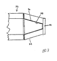
図3は、異なる陽極アセンブリー34を有するけれども、円錐の一部分を画定する内面36をなお包含しているX線管アセンブリー32の一部分を示す。この陽極アセンブリーでは、薄膜ターゲット38は円錐形内面36から端部窓40を横断して広がっている。この構成の目的は、好ましくは小型X線管であるX線管からのX線フラックスを増大させることである。陽極は本質的に細長く、端部には端部窓40がある。円錐形内面36と端部窓40との上の薄膜ターゲット38で発生したX線は、所望の場合には軸方向を含む広い角度範囲にわたって放射され得る。この切頭円錐構造は、材料の単一の部材から製造された陽極本体でも達成され得る。
FIG. 3 shows a portion of
図4は、本発明の他の重要な実施態様を含むX線管アセンブリー42の一部分を横断面図で示す。本発明のこの形は好ましくは約1mm程度の外径を有する小型X線管で具体化されるけれども、同様の構造をより大きな管に適用することができる。陽極アセンブリー44は、X線管の末端部に示されていて、端部には真空排気ポート46と、図面では摘み切られて示されている好ましくは銅を含むチュービュレーション48とがある。該陽極アセンブリーの主要な構成要素は陽極本体50であり、これは、ベリリウム、酸化ベリリウム、窒化ホウ素、窒化アルミニウム、窒化ケイ素、ダイヤモンド、酸化アルミニウム、或いはアルミニウム−ベリリウム合金などの低−Z、高熱伝導率材料から形成されていて、図示されているように軸方向穴を有する。窒化アルミニウムは、効率的製造と、容認しうるX線透過率及び熱伝導率とに配慮して、使用されている。多くのアプリケーションについての1つの付加的な利点は、窒化アルミニウムがベリリウム或いはダイヤモンドなどの材料より大きな低エネルギーX線吸収を提供することであり、このことは、放射照射量が高エネルギーX線のみに関して最良に管理される場合に望ましい。管フレーム58は、陽極−フレーム間シール60の箇所で陽極アセンブリー44に相対して密封される。このシールは、好ましい実施態様では、銅−銀・活性金属ろう付け合金であるクシルエービーエー(Cusil ABA)などの材料を用いるろう付けにより達成される。その代わりとして、陽極本体50及び管フレーム58のそれの中間の熱膨張特性を有するコバール、モリブデン又はタンタルなどの中間材を用いることができる。陽極−フレーム間シール60は、これら2つの構成部分の間に高完全性のシールを作るためにろう付け温度に熱せられるろう付け材料に加えてコバール、モリブデン又はタンタルのワッシャーを含むことができる。
FIG. 4 illustrates a cross-sectional view of a portion of an
この陽極本体は、より小さな直径まで先細にされ、或いは図4に示されているように末端部を丸くされても良い。陽極本体50の末端部はチュービュレーション・シール52の箇所でチュービュレーション48と接し、それは、もしチュービュレーション48が銅から形成されるのであれば、銅−銀・活性金属合金結合材であって良い。図示されているように、この実施態様では、陽極アセンブリー44はチュービュレーション48と共に、ゲッター56を包含するゲッター空洞54を形成する。このゲッター56は、図4に示されているようにペレットの形であって良く、或いはストリップ又はリングであっても良い。
The anode body may be tapered to a smaller diameter, or the end may be rounded as shown in FIG. The end of the anode body 50 contacts the
図1,3及び4において組み立てられている構成部分の全ては軸対称である。しかし、チュービュレーション48は、陽極本体上の他の場所に置かれても良い。
All of the components assembled in FIGS. 1, 3 and 4 are axisymmetric. However, the
図4において、陽極アセンブリー44は、真空排気ポート46で終わる円錐台状の内面62を有する。円錐形内面62にコーティングされている薄膜ターゲット20は陽極自体を含む。真空排気ポート46は、図示されている実施態様においてより大きな直径の通路64に開いて、チュービュレーション48と共同してゲッター空洞54を形成する。
In FIG. 4, the
該ゲッター位置は、血管又は他の管腔におけるX線治療などの一定のアプリケーションのために追加の利点を提供することができる。管の末端66からの軸方向68に沿ってのX線の伝導を妨げることが重要であることが良くある。図5Aに示されているように、ゲッター56とチュービュレーション48とは厳密な軸方向へのX線放射を或る程度妨げる。ゲッター56とチュービュレーション48とは、最小限の軸方向遮断が望ましければ、最小限の直径を持つことができ、遮断された領域70は軸に沿う細い円錐として示されている。X線は、ターゲットの全ての部分から放射される。放射されるX線の分布は、アプリケーションの必要に応じて、より等方性であるように或いはより特殊化するように、調整され得る。末端の、軸方向に組み込まれたゲッターは、該ゲッターの半径方向及び軸方向の大きさを調整することによって、前方への放射分布を大幅に変化させることができる。図5Bは、薄膜ターゲット20を支持する円錐形内面62aの角度を大きくし、またチュービュレーション48及びゲッター56の直径を大きくすることによって、放射の前方分布が大きく広く減少させられることが示されている。
The getter location can provide additional benefits for certain applications such as x-ray therapy in blood vessels or other lumens. It is often important to prevent X-ray conduction along the
図6は,X線管の処理の後に真空排気ポート46を密封するように陽極本体16に直接組み込まれた陽極シール72を含む他の実施態様を示す。陽極シール72はインジウム又は金などの単一の材料から形成され得るけれども、図6に示されているように2つの材料から形成されても良い。2つの材料を用いれば、陽極からのX線放射パターンをより柔軟に形成することが可能になる。金などの高−Z陽極プラグ74は管軸に沿ってのX線伝導を阻止することができ、インジウムなどの別の材料は気密シール76を提供することができる。陽極本体16が酸化ベリリウム、窒化ホウ素、窒化アルミニウム、窒化ケイ素、ダイヤモンド又は酸化アルミニウムなどの非伝導性材料を含むならば、高−Z陽極プラグ74と気密シール76とは薄膜ターゲット20との電気接続のためにも使用され得る。
FIG. 6 shows another embodiment that includes an
不均一な組成を有する陽極本体を製造することにより、1つ以上の利点が得られる。第1に、より高いZの元素の割合を陽極本体内における位置と共に変化させることによってX線放射の空間分布及び/又はエネルギー分布を変化させることができる。第2に、陽極本体の組成を変化させることによって熱膨張係数を変化させ、これにより陽極を異種のフレーム材料およびチュービュレーション材料に結合させる能力を高めることができる。第3に、陽極の熱伝導率を組成で調整してより効率的な熱伝達プロフィールを提供することができる。その様な段階的組成を達成するために、窒化アルミニウムをいろいろな濃度の、酸化マグネシウム、酸化カルシウム、酸化サマリウム又は他の希土類酸化物などの焼結材料と組み合わせることができる。 By producing an anode body having a non-uniform composition, one or more advantages are obtained. First, the spatial distribution and / or energy distribution of X-ray radiation can be changed by changing the proportion of higher Z elements with the position in the anode body. Second, the coefficient of thermal expansion can be changed by changing the composition of the anode body, thereby increasing the ability to bond the anode to dissimilar frame and tubulation materials. Third, the thermal conductivity of the anode can be adjusted by composition to provide a more efficient heat transfer profile. To achieve such a graded composition, aluminum nitride can be combined with various concentrations of sintered materials such as magnesium oxide, calcium oxide, samarium oxide or other rare earth oxides.
図7Aは、図7Cの付随線図82で概略的に示された半径方向組成勾配で成分B80を通して分布させられた成分A78から構成された陽極本体16を示している。線図82において、原子番号が半径と共に変化するパーセンテージとして示されている。図7Aの破線は成分A78の濃度変化を表す。図7Aにおいて、成分Aの濃度は陽極表面で高くて、中心軸の方に向かって低下する。このタイプの勾配は,X線分布を整形するために望ましい可能性がある。
FIG. 7A shows an
図7Bは、成分C84及び成分D86から構成される陽極本体16を示し、軸方向組成勾配が図7Dの付随線図88に概略的に示されている。線図88において、原子番号が軸方向位置と共に変化するパーセンテージとして示されている。図7Aの破線は、成分D86の濃度変化を表す。この軸方向組成勾配は、たとえば、物理蒸着法或いは化学蒸着法により、或いは溶融物或いはスラリーからのシーケンシャルなデポジションにより得られうる。成分C84の濃度は陽極本体の基端部で高く、末端部に向かって低下する。このタイプの勾配は、熱膨張係数又は熱伝導率、またX線分布を変化させるために望ましい可能性がある。
FIG. 7B shows the
図7A及び7Bの例は2つの成分に言及しているけれども、これらの構想は3種類以上の元素で実現され得る。 Although the example of FIGS. 7A and 7B refers to two components, these concepts can be realized with more than two types of elements.
図7A−7Dに示されている勾配の代わりとして、陽極本体の外面の選択的コーティングによってX線放射パターンの整形及び平均X線放射エネルギーを達成することができる。例えば、窒化アルミニウムのような低−Z元素と19以上のZを有する銀などの1つ以上の元素との物理蒸着或いは化学蒸着により、この目的を達成することができる。 As an alternative to the gradient shown in FIGS. 7A-7D, shaping of the x-ray radiation pattern and average x-ray radiation energy can be achieved by selective coating of the outer surface of the anode body. For example, this goal can be achieved by physical vapor deposition or chemical vapor deposition of a low-Z element such as aluminum nitride and one or more elements such as silver having 19 or more Z.
構成を簡単にするために、おそらく,X線管アセンブリーの内面にゲッター材料を直接デポジットするのが望ましいであろう。この構想が図8に示されていて、薄膜ゲッター90が陽極本体16の内面18にデポジットされる。薄膜ゲッター90は、X線管の動作に影響を及ぼすことなく陽極−フレーム間シール60を横断して管フレーム58の中に広がることができる。
For ease of construction, it may be desirable to deposit getter material directly on the inside surface of the x-ray tube assembly. This concept is illustrated in FIG. 8 in which a
図9は、陽極本体材料16と管フレーム58とがX線管本体92を形成する一体部材である実施態様を示す。この実施態様の利点は、前の図に示されている陽極アセンブリーとフレームとの間の陽極−フレーム間シール60が削除されてX線管アセンブリーが簡単化されていることである。この実施態様では、陽極シール72が幾つかの機能を実行する。X線管本体92が酸化ベリリウム、窒化ホウ素、窒化アルミニウム、窒化ケイ素、ダイヤモンド或いは酸化アルミニウムなどの絶縁材料から製造されるならば、高Z陽極プラグ74と、陽極シール72を構成する気密シール76とは薄膜ターゲット20との電気的接触を提供する。高Z陽極プラグ74は、また、軸方向68に沿ってのX線放射を遮る。管軸に沿ってより多くのX線透過が望まれるならば、低Z導体を使用することができる。気密シール76だけで有効な陽極シール72を達成することができる。
FIG. 9 shows an embodiment in which the
図9に示されている一体のX線管本体92は、図1に示されているゲッター24、図8に示されているデポジットされた薄膜ゲッター90、或いはその他の、前述された小型X線源構造の特徴物を含むように構成され得る。
The integral
図10A及び10Bは、本発明の重要な実施態様を含むX線管の2つの横断面を示す。本発明のこの形は、好ましくは、約1mm程度の外径を有する小型X線管で具体化されるが、同様の構成をより大きな管に適用することができる。図10Aは、X線管の末端部に薄膜ターゲット20を有する陽極本体16と、陽極−フレーム間シール60と、該管の基端部に近い陰極アセンブリー96及び陰極−フレーム間シール98を有するX線管フレーム58とを含むX線管アセンブリー94の横断面を示す。管フレーム58は該管の全長の主要な部分を画定する。真空排気された管は、おおよそ図に示されているポイントA’及びB’の間に延在する。
Figures 10A and 10B show two cross-sections of an x-ray tube that includes an important embodiment of the present invention. This form of the invention is preferably embodied in a small x-ray tube having an outer diameter on the order of about 1 mm, although similar configurations can be applied to larger tubes. FIG. 10A shows an X body having an
図10Bは,X線管の末端部に存する薄膜ターゲット20を有する一体のX線管フレーム92と、該管の基端部に近い陰極アセンブリー96及び陰極シール98とを含むX線管アセンブリー100の横断面を示す。該管は、図10Aの場合と同様にX線管アセンブリー100の全長にわたって延在する。
FIG. 10B illustrates an
図11は、本発明の他の重要な実施態様を含むX線管アセンブリー42の一部を横断面図で示す。陽極アセンブリー44はX線管の末端部に示されて、チュービュレーション・アセンブリー102に相対して密封されており、該チュービュレーション・アセンブリーは、真空排気ポート106を有するチュービュレーション・カラー104と、図面においては摘み切られて図示されている好ましくは銅を含むチュービュレーション108とを含む。陽極アセンブリー44は、陽極−チュービュレーション・アセンブリー間シール110においてチュービュレーション・アセンブリー102に相対して密封されている。陽極−チュービュレーション間シール110は1つの好ましい実施態様では銅−銀活性金属ろう付け合金を含む。管フレーム58は、フレーム−チュービュレーション・アセンブリー間シール112においてチュービュレーション・アセンブリー102の反対側端部に相対して密封されている。これらのシールは、1つの好ましい実施態様では、クシル(Cusil)などの材料を用いてろう付けにより達成される。チュービュレーション・カラー104は、コバール、モリブデン又はタンタルなどの材料を含むことができる。チュービュレーション・カラー104は、チュービュレーション・シール114を介してチュービュレーション108に相対して密封されている。チュービュレーション・シール114は、1つの好ましい実施態様では、クシル又は50%銅−50%金合金から成る。この実施態様に示されているように、チュービュレーション・アセンブリー102はゲッター118を包含するゲッター空洞116を形成する。ゲッター118は、1つの好ましい実施態様では、ストリップ又はリングであって良い。或いは、ゲッター118は、図11Bに示されているようにチュービュレーション108の中に置かれても良い。
FIG. 11 illustrates a cross-sectional view of a portion of an
上記のように、これらの好ましい実施態様におけるX線管アセンブリー94又は100のサイズは非常に小さい。該管の外部直径は約1mm程度であって良く、該管の陰極から陽極までの長さは約8或いは9mmであって良い。これは、治療のための非常に局所化されたX線線量を管理するために身体の管腔その他の空洞で使用され得る小型の切り替え可能なX線源を提供する。
As noted above, the size of the
上記の好ましい実施態様は、本発明の原理を具体的に説明するように意図されているが、その範囲を限定するように意図されてはいない。他の実施態様と、この好ましい実施態様に対する変更とは、当業者にとっては明白であって、次に述べる請求項において定義されている発明の範囲から逸脱することなく行われ得る。 The preferred embodiments described above are intended to illustrate the principles of the invention, but are not intended to limit the scope thereof. Other embodiments and modifications to this preferred embodiment will be apparent to those skilled in the art and may be made without departing from the scope of the invention as defined in the following claims.
Claims (26)
X線管の一部を画定する内部空洞を有する管フレームと;
電子を放出するための、該管フレームの一端に存する陰極アセンブリーと;
該管フレームの反対側端部に存する陽極アセンブリーと、ここで該陽極アセンブリーは内部空洞を有する陽極本体を含んでおり、該陽極本体の第1の端部は該管フレームの反対側端部と共に密封されて完全なX線管空洞を形成し、該陽極本体の第2の端部には該管フレームとほぼ同軸の円錐形内表面が形成されており;および
該円錐形内表面にはコーティングされたX線発生薄膜ターゲットとを含んでおり、ここで該陽極本体が、X線を透過し、該陽極本体の第2の端部から放射されるX線に関しては広範囲な分布を与え、かつ該陽極本体の外側と冷媒が接触することによって効率良く冷却されるように、該陽極本体の第2の端部は、その外側が丸いか或いは弾丸形に形成され、またその内側は該円錐形内表面およびその上にコーティングされたターゲットが丸いか或いは弾丸形に形成された外表面に近接するように形成されており、またその円錐形内表面から外側にかけては所望のX線透過性および所望の熱伝導性を有する材料で構成されている、X線管アセンブリー。 An x-ray tube assembly, the x-ray tube assembly comprising:
A tube frame having an internal cavity defining a part of the X-ray tube;
For emitting electron, and a cathode assembly that exists at one end of the tube frame;
An anode assembly that exists at the opposite end of the tube frame, wherein the anode assembly includes an anode body having an internal cavity, a first end portion of the anode body with opposite end portions of the tube frame are sealed to form a complete X-ray tube cavity, the second end portion of the anode body is formed with a substantially coaxial conical inner table surface with said tube frame; and
The said conical inner table surface includes an X-ray generating thin film target coated, wherein the anode body is transmitted through the X-ray, X-rays emitted from the second end of the anode body The second end of the anode body is rounded or bullet-shaped so that it has a wide distribution and is cooled efficiently by contact of the refrigerant with the outside of the anode body. And the inside is formed such that the conical inner surface and the target coated thereon are close to the round or bullet shaped outer surface, and from the conical inner surface to the outer side. Is an X-ray tube assembly made of a material having the desired X-ray transparency and the desired thermal conductivity.
Applications Claiming Priority (3)
| Application Number | Priority Date | Filing Date | Title |
|---|---|---|---|
| US10/371,401 | 2003-02-21 | ||
| US10/371,401 US7158612B2 (en) | 2003-02-21 | 2003-02-21 | Anode assembly for an x-ray tube |
| PCT/US2004/005302 WO2004077481A2 (en) | 2003-02-21 | 2004-02-23 | Anode assembly for an x-ray tube |
Publications (2)
| Publication Number | Publication Date |
|---|---|
| JP2006518921A JP2006518921A (en) | 2006-08-17 |
| JP4986220B2 true JP4986220B2 (en) | 2012-07-25 |
Family
ID=32868325
Family Applications (1)
| Application Number | Title | Priority Date | Filing Date |
|---|---|---|---|
| JP2006503802A Expired - Fee Related JP4986220B2 (en) | 2003-02-21 | 2004-02-23 | Anode assembly for X-ray tube |
Country Status (4)
| Country | Link |
|---|---|
| US (1) | US7158612B2 (en) |
| EP (1) | EP1599883B1 (en) |
| JP (1) | JP4986220B2 (en) |
| WO (1) | WO2004077481A2 (en) |
Families Citing this family (23)
| Publication number | Priority date | Publication date | Assignee | Title |
|---|---|---|---|---|
| US20060173232A1 (en) * | 2003-06-18 | 2006-08-03 | Lovoi Paul A | HDR adapter for electronic radiation source applicator |
| JP5128752B2 (en) * | 2004-04-07 | 2013-01-23 | 日立協和エンジニアリング株式会社 | Transmission X-ray tube and manufacturing method thereof |
| US7346147B2 (en) * | 2005-07-27 | 2008-03-18 | Kirk Randol E | X-ray tube with cylindrical anode |
| SE532723C2 (en) * | 2007-05-03 | 2010-03-23 | Lars Lantto | Device for generating X-rays with great real focus and needs-adapted virtual focus |
| US7983396B2 (en) * | 2007-05-16 | 2011-07-19 | Passport Systems, Inc. | Thin walled tube radiator for bremsstrahlung at high electron beam intensities |
| GB2453570A (en) * | 2007-10-11 | 2009-04-15 | Kratos Analytical Ltd | Electrode for x-ray apparatus |
| US7965818B2 (en) * | 2008-07-01 | 2011-06-21 | Minnesota Medical Physics Llc | Field emission X-ray apparatus, methods, and systems |
| US20100074407A1 (en) * | 2008-09-19 | 2010-03-25 | Steve Axelrod | Treatment of lesions or imperfections in skin, near-skin or in other anatomic tissues, including under direct visualization |
| US8663210B2 (en) * | 2009-05-13 | 2014-03-04 | Novian Health, Inc. | Methods and apparatus for performing interstitial laser therapy and interstitial brachytherapy |
| JP5670111B2 (en) * | 2009-09-04 | 2015-02-18 | 東京エレクトロン株式会社 | X-ray generation target, X-ray generation apparatus, and method for manufacturing X-ray generation target |
| KR101068680B1 (en) * | 2010-02-03 | 2011-09-29 | 한국과학기술원 | Ultra-small X-ray tube using nanomaterial field emission source |
| DE102010030713B4 (en) * | 2010-02-17 | 2018-05-03 | rtw RÖNTGEN-TECHNIK DR. WARRIKHOFF GmbH & Co. KG | X-ray source for generating X-rays with a hollow body target and a method for generating X-radiation in a hollow body target |
| KR101151859B1 (en) * | 2010-03-26 | 2012-05-31 | 주식회사엑스엘 | X-ray Tube Having Non-evaporable Getter |
| JP5645449B2 (en) * | 2010-04-14 | 2014-12-24 | キヤノン株式会社 | X-ray source and X-ray imaging apparatus |
| WO2012147034A1 (en) | 2011-04-27 | 2012-11-01 | Koninklijke Philips Electronics N.V. | Energy application apparatus |
| JP5787626B2 (en) * | 2011-06-07 | 2015-09-30 | キヤノン株式会社 | X-ray tube |
| US9941092B2 (en) | 2014-12-03 | 2018-04-10 | Varex Imaging Corporation | X-ray assemblies and coatings |
| US9818569B2 (en) * | 2014-12-31 | 2017-11-14 | Rad Source Technologies, Inc | High dose output, through transmission target X-ray system and methods of use |
| US10847336B2 (en) | 2017-08-17 | 2020-11-24 | Bruker AXS, GmbH | Analytical X-ray tube with high thermal performance |
| DE102017217181B3 (en) * | 2017-09-27 | 2018-10-11 | Siemens Healthcare Gmbh | Steh anode for an X-ray source and X-ray source |
| US11011341B2 (en) * | 2018-05-21 | 2021-05-18 | Varex Imaging Corporation | Transmission target for a high power electron beam |
| US11749490B2 (en) * | 2020-02-17 | 2023-09-05 | Visuray Intech Ltd (Bvi) | Method for reducing the diameter of a x-ray tube through recessing of the vacuum port |
| US20210289610A1 (en) * | 2020-03-10 | 2021-09-16 | Globalfoundries U.S. Inc. | Failure analysis apparatus using x-rays |
Family Cites Families (39)
| Publication number | Priority date | Publication date | Assignee | Title |
|---|---|---|---|---|
| NL16507C (en) * | 1924-07-23 | 1927-07-15 | ||
| US2168780A (en) * | 1930-12-06 | 1939-08-08 | Dimitry E Oishevsky | X-ray tube |
| US3584219A (en) | 1969-01-30 | 1971-06-08 | Du Pont | X-ray generator having an anode formed by a solid block with a conical bore closed by a target toil |
| US3665236A (en) * | 1970-12-09 | 1972-05-23 | Atomic Energy Commission | Electrode structure for controlling electron flow with high transmission efficiency |
| US3892989A (en) * | 1971-03-08 | 1975-07-01 | Watkins Johnson Co | Convergent flow hollow beam X-ray gun construction |
| FR2355428A1 (en) * | 1976-06-14 | 1978-01-13 | Elf Aquitaine | HIGH-EFFICIENCY IRRADIATION DEVICE CONTAINING AN X-RAY GENERATOR TUBE WITH WINDOW ANODE |
| FR2386109A1 (en) * | 1977-04-01 | 1978-10-27 | Cgr Mev | G-RAY IRRADIATION HEAD FOR PANORAMIC IRRADIATION AND G-RAY GENERATOR INCLUDING SUCH IRRADIATION HEAD |
| US4143275A (en) | 1977-09-28 | 1979-03-06 | Battelle Memorial Institute | Applying radiation |
| US4477921A (en) * | 1981-11-27 | 1984-10-16 | Spire Corporation | X-Ray lithography source tube |
| US4431709A (en) * | 1982-09-29 | 1984-02-14 | North American Philips Corporation | Beryllium to metal seals and method of producing the same |
| DE4017002A1 (en) * | 1990-05-26 | 1991-11-28 | Philips Patentverwaltung | Monochromatic X=radiation source |
| US5422926A (en) * | 1990-09-05 | 1995-06-06 | Photoelectron Corporation | X-ray source with shaped radiation pattern |
| US5452720A (en) | 1990-09-05 | 1995-09-26 | Photoelectron Corporation | Method for treating brain tumors |
| US5369679A (en) | 1990-09-05 | 1994-11-29 | Photoelectron Corporation | Low power x-ray source with implantable probe for treatment of brain tumors |
| US5153900A (en) | 1990-09-05 | 1992-10-06 | Photoelectron Corporation | Miniaturized low power x-ray source |
| US5090043A (en) * | 1990-11-21 | 1992-02-18 | Parker Micro-Tubes, Inc. | X-ray micro-tube and method of use in radiation oncology |
| US5422678A (en) | 1991-01-29 | 1995-06-06 | Seiko Epson Corp. | Video processor for enlarging and contracting an image in a vertical direction |
| US5165093A (en) | 1992-03-23 | 1992-11-17 | The Titan Corporation | Interstitial X-ray needle |
| US5329569A (en) * | 1993-02-18 | 1994-07-12 | Sandia Corporation | X-ray transmissive debris shield |
| AU683299B2 (en) * | 1993-09-01 | 1997-11-06 | Ludwig Institute For Cancer Research | Nucleotide sequences for novel protein tyrosine phosphatases |
| US5747245A (en) * | 1994-06-14 | 1998-05-05 | La Jolla Cancer Research Foundation | Nucleic acids encoding Fas associated proteins and screening assays using same |
| CA2194759C (en) | 1994-07-12 | 1999-09-14 | Donald O. Smith | X-ray apparatus for applying a predetermined flux to an interior surface of a body cavity |
| US5566221A (en) | 1994-07-12 | 1996-10-15 | Photoelectron Corporation | Apparatus for applying a predetermined x-radiation flux to an interior surface of a body cavity |
| US5509045A (en) * | 1995-02-09 | 1996-04-16 | Picker International, Inc. | X-ray tube having a getter shield and method |
| US5565164A (en) | 1995-03-17 | 1996-10-15 | Limited Resources, Inc. | Method and apparatus for densifying a thermoplastic polymer |
| US6799075B1 (en) * | 1995-08-24 | 2004-09-28 | Medtronic Ave, Inc. | X-ray catheter |
| US5729583A (en) * | 1995-09-29 | 1998-03-17 | The United States Of America As Represented By The Secretary Of Commerce | Miniature x-ray source |
| DE19544203A1 (en) * | 1995-11-28 | 1997-06-05 | Philips Patentverwaltung | X-ray tube, in particular microfocus X-ray tube |
| JPH1050242A (en) * | 1996-08-05 | 1998-02-20 | Shimadzu Corp | X-ray tube anode, and manufacture thereof |
| EP0860181B1 (en) | 1997-02-21 | 2004-04-28 | Medtronic Ave, Inc. | X-ray device having a dilatation structure for delivering localized radiation to an interior of a body |
| US5802140A (en) * | 1997-08-29 | 1998-09-01 | Varian Associates, Inc. | X-ray generating apparatus with integral housing |
| US6064718A (en) * | 1998-09-29 | 2000-05-16 | The United States Of America As Represented By The Secretary Of The Navy | Field emission tube for a mobile X-ray unit |
| US6154521A (en) * | 1998-10-26 | 2000-11-28 | Picker International, Inc. | Gyrating anode x-ray tube |
| US6134300A (en) | 1998-11-05 | 2000-10-17 | The Regents Of The University Of California | Miniature x-ray source |
| US6319188B1 (en) | 1999-04-26 | 2001-11-20 | Xoft Microtube, Inc. | Vascular X-ray probe |
| US6195411B1 (en) * | 1999-05-13 | 2001-02-27 | Photoelectron Corporation | Miniature x-ray source with flexible probe |
| US6353658B1 (en) * | 1999-09-08 | 2002-03-05 | The Regents Of The University Of California | Miniature x-ray source |
| US6580780B1 (en) * | 2000-09-07 | 2003-06-17 | Varian Medical Systems, Inc. | Cooling system for stationary anode x-ray tubes |
| US6721392B1 (en) * | 2001-12-04 | 2004-04-13 | Carl-Zeiss-Stiftung | Optically driven therapeutic radiation source including a non-planar target configuration |
-
2003
- 2003-02-21 US US10/371,401 patent/US7158612B2/en not_active Expired - Lifetime
-
2004
- 2004-02-23 JP JP2006503802A patent/JP4986220B2/en not_active Expired - Fee Related
- 2004-02-23 EP EP04713782.3A patent/EP1599883B1/en not_active Expired - Lifetime
- 2004-02-23 WO PCT/US2004/005302 patent/WO2004077481A2/en active Application Filing
Also Published As
| Publication number | Publication date |
|---|---|
| US7158612B2 (en) | 2007-01-02 |
| WO2004077481A3 (en) | 2005-06-09 |
| EP1599883A4 (en) | 2010-03-24 |
| WO2004077481A2 (en) | 2004-09-10 |
| JP2006518921A (en) | 2006-08-17 |
| EP1599883A2 (en) | 2005-11-30 |
| US20040165699A1 (en) | 2004-08-26 |
| EP1599883B1 (en) | 2013-09-25 |
Similar Documents
| Publication | Publication Date | Title |
|---|---|---|
| JP4986220B2 (en) | Anode assembly for X-ray tube | |
| US6353658B1 (en) | Miniature x-ray source | |
| US7086577B2 (en) | Method of manufacturing a miniature X-ray device | |
| JP5800578B2 (en) | X-ray tube | |
| US9029795B2 (en) | Radiation generating tube, and radiation generating device and apparatus including the tube | |
| US20030002627A1 (en) | Cold emitter x-ray tube incorporating a nanostructured carbon film electron emitter | |
| US5157704A (en) | Monochromatic x-ray tube radiation with a screen of high atomic number for higher fluorescent radiation output | |
| US6771737B2 (en) | X-ray catheter with miniature emitter and focusing cup | |
| US10643816B1 (en) | X-ray emitting device comprising a focusing electrode composed of a ceramic-based material | |
| JP2013051165A (en) | Transmission x-ray generator | |
| KR20020038737A (en) | Light source and method for producing a light source | |
| CN107919257A (en) | Carbon nanotubes microbeam array field emission cathode Microfocus X-ray X-ray tube | |
| US20020063500A1 (en) | Miniature X-ray tube constructions | |
| US6621219B2 (en) | Thermally insulating lead wire for ceramic metal halide electrodes | |
| CN215183845U (en) | Small-sized X-ray tube | |
| JP2002298772A (en) | Transmissive radiation type x-ray tube and producing method thereof | |
| JP2000082430A (en) | Target for x-ray generation and x-ray tube using the same | |
| TW200305912A (en) | Short-arc lamp with dual concave reflectors and a transparent arc chamber | |
| JPH02297850A (en) | Target for x-ray generating tube and x-ray generating tube | |
| EP0505472A1 (en) | Electrode feedthrough connection strap for arc discharge lamp | |
| CN219610346U (en) | X-ray tube | |
| CN117877953A (en) | X-ray source shielding | |
| CN117423590A (en) | Miniature X-ray tube and X-ray generating device | |
| JPH0917383A (en) | Fluorescent lamp | |
| KR20180028634A (en) | Field Emission X-Ray Source Device |
Legal Events
| Date | Code | Title | Description |
|---|---|---|---|
| A621 | Written request for application examination |
Free format text: JAPANESE INTERMEDIATE CODE: A621 Effective date: 20070214 |
|
| RD04 | Notification of resignation of power of attorney |
Free format text: JAPANESE INTERMEDIATE CODE: A7424 Effective date: 20100329 |
|
| A131 | Notification of reasons for refusal |
Free format text: JAPANESE INTERMEDIATE CODE: A131 Effective date: 20100706 |
|
| A601 | Written request for extension of time |
Free format text: JAPANESE INTERMEDIATE CODE: A601 Effective date: 20101004 |
|
| A602 | Written permission of extension of time |
Free format text: JAPANESE INTERMEDIATE CODE: A602 Effective date: 20101012 |
|
| A521 | Request for written amendment filed |
Free format text: JAPANESE INTERMEDIATE CODE: A523 Effective date: 20101028 |
|
| TRDD | Decision of grant or rejection written | ||
| A01 | Written decision to grant a patent or to grant a registration (utility model) |
Free format text: JAPANESE INTERMEDIATE CODE: A01 Effective date: 20120403 |
|
| A01 | Written decision to grant a patent or to grant a registration (utility model) |
Free format text: JAPANESE INTERMEDIATE CODE: A01 |
|
| A61 | First payment of annual fees (during grant procedure) |
Free format text: JAPANESE INTERMEDIATE CODE: A61 Effective date: 20120420 |
|
| R150 | Certificate of patent or registration of utility model |
Free format text: JAPANESE INTERMEDIATE CODE: R150 |
|
| FPAY | Renewal fee payment (event date is renewal date of database) |
Free format text: PAYMENT UNTIL: 20150511 Year of fee payment: 3 |
|
| LAPS | Cancellation because of no payment of annual fees |