JP5645449B2 - X-ray source and X-ray imaging apparatus - Google Patents
X-ray source and X-ray imaging apparatus Download PDFInfo
- Publication number
- JP5645449B2 JP5645449B2 JP2010093429A JP2010093429A JP5645449B2 JP 5645449 B2 JP5645449 B2 JP 5645449B2 JP 2010093429 A JP2010093429 A JP 2010093429A JP 2010093429 A JP2010093429 A JP 2010093429A JP 5645449 B2 JP5645449 B2 JP 5645449B2
- Authority
- JP
- Japan
- Prior art keywords
- ray
- ray source
- electron beam
- convex
- transmission
- Prior art date
- Legal status (The legal status is an assumption and is not a legal conclusion. Google has not performed a legal analysis and makes no representation as to the accuracy of the status listed.)
- Expired - Fee Related
Links
Images


Classifications
-
- H—ELECTRICITY
- H01—ELECTRIC ELEMENTS
- H01J—ELECTRIC DISCHARGE TUBES OR DISCHARGE LAMPS
- H01J35/00—X-ray tubes
- H01J35/02—Details
- H01J35/04—Electrodes ; Mutual position thereof; Constructional adaptations therefor
- H01J35/06—Cathodes
- H01J35/065—Field emission, photo emission or secondary emission cathodes
-
- H—ELECTRICITY
- H01—ELECTRIC ELEMENTS
- H01J—ELECTRIC DISCHARGE TUBES OR DISCHARGE LAMPS
- H01J35/00—X-ray tubes
- H01J35/02—Details
- H01J35/16—Vessels; Containers; Shields associated therewith
-
- H—ELECTRICITY
- H01—ELECTRIC ELEMENTS
- H01J—ELECTRIC DISCHARGE TUBES OR DISCHARGE LAMPS
- H01J35/00—X-ray tubes
- H01J35/02—Details
- H01J35/20—Selection of substances for gas fillings; Means for obtaining or maintaining the desired pressure within the tube, e.g. by gettering
-
- H—ELECTRICITY
- H01—ELECTRIC ELEMENTS
- H01J—ELECTRIC DISCHARGE TUBES OR DISCHARGE LAMPS
- H01J2235/00—X-ray tubes
- H01J2235/06—Cathode assembly
- H01J2235/062—Cold cathodes
-
- H—ELECTRICITY
- H01—ELECTRIC ELEMENTS
- H01J—ELECTRIC DISCHARGE TUBES OR DISCHARGE LAMPS
- H01J2235/00—X-ray tubes
- H01J2235/06—Cathode assembly
- H01J2235/068—Multi-cathode assembly
-
- H—ELECTRICITY
- H01—ELECTRIC ELEMENTS
- H01J—ELECTRIC DISCHARGE TUBES OR DISCHARGE LAMPS
- H01J2235/00—X-ray tubes
- H01J2235/16—Vessels
- H01J2235/163—Vessels shaped for a particular application
-
- H—ELECTRICITY
- H01—ELECTRIC ELEMENTS
- H01J—ELECTRIC DISCHARGE TUBES OR DISCHARGE LAMPS
- H01J2235/00—X-ray tubes
- H01J2235/20—Arrangements for controlling gases within the X-ray tube
- H01J2235/205—Gettering
-
- H—ELECTRICITY
- H01—ELECTRIC ELEMENTS
- H01J—ELECTRIC DISCHARGE TUBES OR DISCHARGE LAMPS
- H01J35/00—X-ray tubes
- H01J35/02—Details
- H01J35/04—Electrodes ; Mutual position thereof; Constructional adaptations therefor
- H01J35/08—Anodes; Anti cathodes
- H01J35/112—Non-rotating anodes
- H01J35/116—Transmissive anodes
-
- H—ELECTRICITY
- H01—ELECTRIC ELEMENTS
- H01J—ELECTRIC DISCHARGE TUBES OR DISCHARGE LAMPS
- H01J35/00—X-ray tubes
- H01J35/02—Details
- H01J35/16—Vessels; Containers; Shields associated therewith
- H01J35/18—Windows
-
- H—ELECTRICITY
- H01—ELECTRIC ELEMENTS
- H01J—ELECTRIC DISCHARGE TUBES OR DISCHARGE LAMPS
- H01J35/00—X-ray tubes
- H01J35/02—Details
- H01J35/16—Vessels; Containers; Shields associated therewith
- H01J35/18—Windows
- H01J35/186—Windows used as targets or X-ray converters
Landscapes
- X-Ray Techniques (AREA)
Description
本発明は、透過型ターゲット電極を備えたX線源及びX線撮影装置に関する。 The present invention relates to an X-ray source and an X-ray imaging apparatus provided with a transmissive target electrode.
従来、X線発生装置の電子源には、熱電子源が用いられている。このようなX線発生装置では、高温度に加熱されたフィラメントから放出される熱電子の一部が、ウエネルト電極、引出し電極、加速電極、及びレンズ電極を通して、所定の形状の電子束に成形され、高エネルギに加速される。そして、タングステン等の金属から構成されたターゲット電極に電子束が照射され、X線が発生する。なお、熱電子源として、ブラウン管用の電子源でもある含浸型熱陰極電子放出素子等の小型のものもある。
但し、電子束が有するエネルギのうちX線に変換されるものは1%以下であり、残りのエネルギは熱となる。ターゲット電極の周囲は真空にされているため、熱の大部分は放射熱として放熱されるが、放熱が間に合わない場合、ターゲット電極の温度が上昇し、ターゲット電極が溶融することもあり得る。このため、従来のX線発生装置では、ターゲット電極に衝突する電子の単位面積当たりの量を低くして、ターゲット電極の単位面積当たりに与えられるエネルギが調整されている。電子の単位面積当たりの量を低くするには、電子の照射面積を大きくすることが有効である。
その一方で、ターゲット電極の電子が衝突する部分はX線発生部となる。X線発生部のサイズはX線検出器での分解能に影響を与えるため、X線発生部を必要以上に拡大することは好ましくない。
そこで、これらを両立させるために、電子照射方向に対して、ターゲット電極の表面を傾斜させる技術、及びターゲット電極の表面に微小な凹凸を設ける技術が提案されている。
Conventionally, a thermal electron source has been used as an electron source of an X-ray generator. In such an X-ray generator, some of the thermoelectrons emitted from the filament heated to a high temperature are formed into an electron bundle having a predetermined shape through a Wehnelt electrode, an extraction electrode, an acceleration electrode, and a lens electrode. , Accelerated to high energy. The target electrode made of a metal such as tungsten is irradiated with an electron flux, and X-rays are generated. In addition, as a thermionic source, there is a small-sized one such as an impregnated hot cathode electron-emitting device that is also an electron source for a cathode ray tube.
However, less than 1% of the energy of the electron flux is converted to X-rays, and the remaining energy is heat. Since the periphery of the target electrode is evacuated, most of the heat is dissipated as radiant heat. However, if the heat dissipation is not in time, the temperature of the target electrode may rise and the target electrode may melt. For this reason, in the conventional X-ray generator, the energy per unit area of the target electrode is adjusted by reducing the amount of electrons colliding with the target electrode per unit area. In order to reduce the amount of electrons per unit area, it is effective to increase the electron irradiation area.
On the other hand, the part where the electrons of the target electrode collide becomes an X-ray generation part. Since the size of the X-ray generator affects the resolution of the X-ray detector, it is not preferable to enlarge the X-ray generator more than necessary.
Therefore, in order to achieve both of these, a technique for inclining the surface of the target electrode with respect to the electron irradiation direction and a technique for providing minute irregularities on the surface of the target electrode have been proposed.
しかしながら、上述のようなターゲット電極の表面を傾斜させる技術、及びターゲット電極の表面に微小な凹凸を設ける技術では、X線取り出し方向により焦点サイズが異なり、分解能が低下する虞がある。これは、電子ビームの照射領域の面積はX線取り出し方向により幾何学的に変化するためである。そして、分解能が低下する虞があるために、詳細な分解能が必要なX線撮影の際には、撮影者等がX線ターゲットの傾斜方向を確認し、焦点サイズの見かけ上小さくなる領域を考慮した配置にするように設定する必要がある。つまり、従来のX線発生装置を用いて詳細な分解能が必要なX線撮影を行うためには、煩雑な準備が必要とされる。 However, in the technique for inclining the surface of the target electrode as described above and the technique for providing minute irregularities on the surface of the target electrode, the focal spot size differs depending on the X-ray extraction direction, and the resolution may be reduced. This is because the area of the electron beam irradiation region changes geometrically depending on the X-ray extraction direction. Since there is a possibility that the resolution may be reduced, when performing X-ray imaging that requires detailed resolution, a photographer or the like confirms the tilt direction of the X-ray target and considers a region where the focal size is apparently reduced. It is necessary to set so that the arrangement is the same. That is, in order to perform X-ray imaging that requires detailed resolution using a conventional X-ray generator, complicated preparation is required.
本発明は、照射方向による焦点サイズの変化を抑制することができるX線源及びX線撮影装置を提供することを目的とする。 An object of this invention is to provide the X-ray source and X-ray imaging apparatus which can suppress the change of the focus size by an irradiation direction.
本発明に係るX線源は、電子線を放出する電子放出源と、前記電子線の照射によりX線を発生するX線発生層と、前記X線発生層を支持する透過基材とを備えた透過型ターゲットと、を有し、前記透過型ターゲットは、前記電子線の照射を受ける側の面において、前記電子線の入射方向に対して傾斜した傾斜面を備えた複数の凸部を備え、前記凸部は、複数の方向に配列されていることを特徴とする。 An X-ray source according to the present invention includes an electron emission source that emits an electron beam, an X-ray generation layer that generates X-rays upon irradiation of the electron beam, and a transmissive substrate that supports the X-ray generation layer. has been a transmission type target, and the transmission type target is in the plane of the side receiving irradiation of the electron beam, comprises a plurality of protrusions having an inclined surface inclined relative to the direction of said electron beam The convex portions are arranged in a plurality of directions .
本発明によれば、透過ターゲット電極の放熱を高効率で行いながら、照射方向によるX線の焦点サイズの変化を抑制することができる。 ADVANTAGE OF THE INVENTION According to this invention, the change of the focus size of the X-ray according to an irradiation direction can be suppressed, performing the heat dissipation of a permeation | transmission target electrode with high efficiency.
以下、本発明の実施形態について添付の図面を参照して具体的に説明する。 Hereinafter, embodiments of the present invention will be specifically described with reference to the accompanying drawings.
(第1の実施形態)
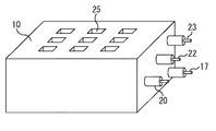
先ず、第1の実施形態について説明する。図1は、本発明の第1の実施形態に係るX線源の内部の構成を示す図であり、図2は、第1の実施形態に係るX線源の外観を示す図である。
第1の実施形態に係るX線源10では、筐体30の内部が真空室11となっており、真空室11に電子線発生部12及び透過型ターゲット電極13が配置されている。電子線発生部12には、素子基板14及び素子アレイ16が設けられている。素子アレイ16はモリブデン等の高融点金属材料からなり、例えば、その直径は5mmである。素子アレイ16の頭頂部に電子放出素子15が搭載されている。また、電子放出素子15としては、例えば含浸型熱陰極電子放出素子が用いられる。電子放出素子15として、数10nmの微細な構造体からなるカーボンナノチューブを用いた冷陰極電子放出素子が用いられてもよい。素子アレイ16の底部は素子基板14の駆動配線に接続されている。素子基板14の駆動配線は駆動信号端子17に接続されている。駆動信号端子17は筐体30を貫通しており、駆動信号端子17には、電子放出素子15からの電子の放出量を制御する信号が入力される。従って、駆動信号端子17への入力信号により、X線のオン/オフが制御される。図3に示すように、駆動信号端子17から、例えば−0.01kV〜−0.2kV程度の電圧Vcが素子アレイ16に供給される。
なお、真空室11の真空度は電子放出のため、例えば10-4Pa〜10-8Pa以下とされる。真空度が高いほど電子放出素子15の寿命が長くなり、放電減少等の問題が発生しにくくなる。
(First embodiment)
First, the first embodiment will be described. FIG. 1 is a diagram showing an internal configuration of an X-ray source according to the first embodiment of the present invention, and FIG. 2 is a diagram showing an external appearance of the X-ray source according to the first embodiment.
In the
Note that the degree of vacuum in the
素子基板14上には、素子アレイ16及び電子放出素子15の総厚よりも厚いスペーサ(間隔規定部材)18が配置されている。スペーサ18には、素子アレイ16及び電子放出素子15と整合する開口部が形成されている。そして、スペーサ18上に引出し電極19が配置されている。引出し電極19の電子放出素子15側の面と電子放出素子15の引出し電極19側の面とは、数百μm程度、互いから離間している。従って、引出し電極19と電子放出素子15及び素子アレイ16とは互いから電気的に絶縁されている。また、引出し電極19の電子放出素子15と対向する部分には、複数の貫通孔が格子状に形成されている。例えば、貫通孔の平面形状は一辺の長さが約0.40mmの正方形であり、貫通孔同士の間隔は約0.1mmである。引出し電極19は、例えば厚さが約0.2mmのタングステンシートに貫通孔を形成したものである。引出し電極19は引出し電極端子20に接続されている。引出し電極端子20は筐体30を貫通しており、引出し電極端子20には、電子放出素子15に加わる電界を制御する電圧が供給される。図3に示すように、引出し電極端子20から、例えば0kVの電圧Vgが引出し電極19に供給される。引出し電極19と素子アレイ16との間に電位差が生じると、電子放出素子15が電子を放出し、引出し電極19を電子ビームが通過する。
なお、引出し電極19の貫通孔の形状、大きさ及び配置等は、電子放出素子15に均一な電界を印加することができれば特に限定されない。また、引出し電極19の面上に、ゲッタ26用に絶縁層又は配線等が設けられていてもよい。
On the
Note that the shape, size, arrangement, and the like of the through holes of the
引出し電極19と透過型ターゲット電極13との間に、レンズ電極(中間電極)21が配置されている。レンズ電極21は、例えば厚さが2mmのステンレス板である。レンズ電極21の材料として、他の導電性の金属を用いてもよく、モリブデン、タングステン、及びタンタル等の原子番号の高い金属であることが望ましい。レンズ電極21はレンズ電極端子22に接続されている。レンズ電極端子22は筐体30を貫通しており、レンズ電極端子22には、引出し電極19を通過した電子線42を収束させ、電子ビーム束43を成形する電圧が供給される。図3に示すように、レンズ電極端子22から、例えば0kV〜10kV程度の電圧Vmがレンズ電極21に供給される。この結果、直径が0.3mm〜2mm程度に収束した電子ビーム束43が得られる。
A lens electrode (intermediate electrode) 21 is disposed between the
透過型ターゲット電極13の周囲には、透過型ターゲット電極13と機械的かつ熱的に接触する真空内X線遮蔽板24が設けられている。真空内X線遮蔽板24には、電子ビーム束43が通過する開口部、及び透過型ターゲット電極13から発せられたX線が通過する開口部が形成されている。透過型ターゲット電極13に発生した熱は、真空内X線遮蔽板24を介して放出される。透過型ターゲット電極13はターゲット電極端子23に接続されている。ターゲット電極端子23は筐体30を貫通しており、ターゲット電極端子23には、電子ビーム束43を加速させる電圧が供給される。図3に示すように、ターゲット電極端子23から、例えば約40kV〜120kV程度の高電圧Vaがターゲット電極13に供給される。この結果、電子ビーム束43が高速で透過型ターゲット電極13に衝突し、X線41が発生する。X線41は透過型ターゲット電極13を透過するが、X線41の一部は真空内X線遮蔽板24により遮蔽され、所定のX線放射角で放出される。
筐体30のX線41が照射する位置にはX線透過窓25が設けられており、X線41はX線透過窓25を透過してX線源10の外部へと放射される。X線透過窓25の材料は、例えば、アルミニウム、ベリリウム銅合金、又はガラス等である。
Around the
An
ここで、透過型ターゲット電極13について詳細に説明する。図4は、第1の実施形態における透過型ターゲット電極13の構造を示す図である。図4(a)は断面図であり、図4(b)は斜視図である。
図4に示すように、透過型ターゲット電極13では、X線発生支持層13a上にX線発生層13bが形成されている。X線発生支持層13aとしては、例えば軽元素からなる基板(基体)が用いられる。また、X線発生支持層13aの材料としては、ダイヤモンド、カーボン、ベリリウム、Al、AlN、及びSiC等のX線吸収能が低いものが挙げられる。これらの材料の2種類以上が組み合わされていてもよい。X線発生支持層13aの厚さは、例えば0.1mm〜数mm程度である。また、X線発生層13bの材料としては、タングステン、モリブデン等の重金属が挙げられる。X線発生層13bの厚さは、例えば数10nm〜数μm程度である。透過型ターゲット電極13の厚さtは、例えば0.5mm程度である。
更に、本実施形態では、X線発生支持層13aの表面に凹凸部38が形成され、この凹凸部38に倣うようにX線発生層13bが形成されている。このため、透過型ターゲット電極13の表面に凹凸部38が存在する。凹凸部38の凸部の形状は、例えば四角錐であり、その高さdは約0.05mmである。そして、凹凸部38の凸部の傾斜面とX線41の入射方向とがなす角度θは例えば45度に設定されている。
Here, the
As shown in FIG. 4, in the
Furthermore, in this embodiment, the uneven | corrugated |
このように構成された透過型ターゲット電極13では、X線発生層13bの材料及び厚さが適切であるため、X線41が透過型ターゲット電極13に吸収されにくく、強度が減衰しにくい。また、X線発生支持層13aの材料及び厚さが適切であるため、電子ビーム束43の照射により昇温したX線発生層13bを高効率で冷却することが可能であり、また、X線41が透過型ターゲット電極13に吸収されにくく、強度が減衰しにくい。つまり、X線発生支持層13aの熱伝導性が高く、また、X線発生支持層13aにおけるX線41の透過性が優れている。更に、X線発生支持層13aは、X線41の低エネルギ領域でX線透過像の像質への寄与が少ないエネルギの低いX線41を有効に吸収し、X線の線質を変えるフィルタとしても機能する。従って、透過型ターゲット電極13でのX線41の発生効率が高く、機能性に優れている。
また、透過型ターゲット電極13の表面に、適切な形状及び大きさの凹凸部38が形成されているため、透過型ターゲット電極13の表面積が、平面となっている場合と比較して約2倍程度になっている。このため、透過型ターゲット電極13の受ける単位表面積当たりの電子エネルギは約1/2となる。よって、透過型ターゲット電極13の表面温度の上昇を抑制することができる。
更に、凹凸部38の凸部の傾斜面のX線41の入射方向に対する角度θが45度なので、ある斜面からの熱放射が、これに隣接する斜面に照射されることがなく、効率よく熱放射が行われる。また、上述のように、真空内X線遮蔽板24(放熱部材)を介した放熱も行われる。従って、本実施形態によれば、被検体の透過に十分な量のX線が放射される程度の電力投入が可能である。
In the
In addition, since the
Furthermore, since the angle θ of the inclined surface of the convex portion of the concavo-
更にまた、上述のように、凹凸部38に電子線42の電子ビーム束43が衝突すると、凹凸部38の表面からX線41が発生するが、X線41の放射方向は、微小な凹凸部38の各部から発生したX線の照射方向の集合となる。従って、X線41のどのような照射方向においても、X線41が発生している部分はほとんど同一である。そして、X線41が複数の凹凸部38の斜面から照射されたものであるため、その焦点サイズがほぼ一定となる。このため、X線41の照射方向による分解能の変化を抑制することができる。
例えば、図5(a)に示すように、透過型ターゲット電極13の表面から電子ビーム束43の入射方向に放射されたX線41aの焦点サイズ53と、電子ビーム束43の入射方向から傾斜した方向に放射されたX線41bの焦点サイズ54とが互いに同等となる。このようにして、分解能の変化を抑制することができる。
Furthermore, as described above, when the electron beam bundle 43 of the
For example, as shown in FIG. 5A, the focal point size 53 of the X-ray 41 a emitted from the surface of the
このような第1の実施形態によれば、十分なエネルギでX線41を発生させることができ、また、照射方向に拘わらず、X線41の焦点サイズ、つまり電子照射面積を安定させることができる。このため、このようなX線源10を用いれば、X線センサの全面でほぼ同一の分解能でのX線撮影が可能になる。
According to the first embodiment, the
なお、図5(b)に示すような斜面を備えた透過型ターゲット電極102を用いた場合には、透過型ターゲット電極102の表面から電子ビーム束101の入射方向に放射されたX線の焦点サイズ103が、電子ビーム束101の入射方向から傾斜した方向に放射されたX線の焦点サイズ104よりも著しく小さくなり得る。この場合、X線の照射方向により分解能が著しく相違してしまう。このような問題点は、特許文献1に記載の技術に生じる。
また、図5(c)に示すようなターゲット電極112に電子ビーム束111を照射した場合には、ターゲット電極112の表面から浅い角度で放射されたX線の焦点サイズ113が、ターゲット電極112の表面から大きな角度で放射された焦点サイズ114よりも著しく小さくなり得る。この場合、X線の照射方向により分解能が著しく相違してしまう。このような問題点は、特許文献2に記載の技術に生じる。
When the transmission target electrode 102 having a slope as shown in FIG. 5B is used, the focal point of X-rays emitted from the surface of the transmission target electrode 102 in the incident direction of the electron beam bundle 101. The size 103 can be significantly smaller than the focal size 104 of X-rays emitted in a direction inclined from the incident direction of the electron beam bundle 101. In this case, the resolution is significantly different depending on the X-ray irradiation direction. Such a problem occurs in the technique described in Patent Document 1.
In addition, when the target electrode 112 as shown in FIG. 5C is irradiated with the
(第2の実施形態)
次に、第2の実施形態について説明する。図6は、本発明の第2の実施形態における透過型ターゲット電極13の構造を示す図である。
第1の実施形態では、凹凸部38の凸部同士が四角錘の底辺を介して繋がっているのに対し、第2の実施形態では、凸部同士が凹球面82を介して繋がった凹凸部81が透過型ターゲット電極13の表面に形成されている。凹球面82の曲率半径は半径約0.01mmである。
(Second Embodiment)
Next, a second embodiment will be described. FIG. 6 is a diagram showing the structure of the
In the first embodiment, the convex portions of the concave and
このような第2の実施形態によっても第1の実施形態と同様の効果を得ることができる。また、電子ビーム束43の照射に伴って透過型ターゲット電極13の温度が上昇し、熱応力が発生しても、凹球面82があるため、応力集中が緩和される。このため、第1のじっ形態よりも亀裂等が生じにくく、駆動時の信頼性が向上する。
The effect similar to 1st Embodiment can be acquired also by such 2nd Embodiment. Even if the temperature of the
(第3の実施形態)
次に、第3の実施形態について説明する。第3の実施形態は、第1又は第2の実施形態に係るX線源10を備えたX線撮影装置である。図7は、本発明の第3の実施形態に係るX線撮影装置の構成を示す図である。
第3の実施形態に係るX線撮影装置には、X線源10からのX線の放射方向に、X線検出器31が配置されている。撮影時には、X線検出器31のX線源10側に被検体が位置する。
X線検出器31は、信号処理部32を介して中央制御部33に接続されている。また、中央制御部33には、高電圧制御部34、電圧制御部35、電圧制御部36、及び電子放出素子駆動回路37が接続されている。高電圧制御部34にターゲット電極端子23が接続され、電圧制御部35にレンズ電極端子22が接続され、電圧制御部36に引出し電極端子20が接続され、電子放出素子駆動回路37に駆動信号端子17が接続される。
(Third embodiment)
Next, a third embodiment will be described. The third embodiment is an X-ray imaging apparatus including the
In the X-ray imaging apparatus according to the third embodiment, an
The
このように構成されたX線撮影装置では、中央制御部33の制御により高電圧制御部34、電圧制御部35、電圧制御部36、及び電子放出素子駆動回路37が動作して、X線41が発生する。即ち、X線源10の電子線発生部12により発せられた電子の電子線42が収束して電子ビーム束43が得られ、電子ビーム束43が透過型ターゲット電極13に照射されてX線41が発生する。X線41はX線透過窓25を通して大気中に放射され、被検体を介してX線検出器31に検出される。そして、中央制御部33の制御により信号処理部32が動作して、X線検出器31の検出結果から被検体のX線透過画像を作成する。
そして、第3の実施形態では、第1又は第2の実施形態に係るX線源10が用いられているため、十分なエネルギでX線41を発生させることができ、また、照射方向に拘わらず、X線41の焦点サイズ、つまり電子照射面積を安定させることができる。
In the X-ray imaging apparatus configured as described above, the high
In the third embodiment, since the
なお、凹凸部の凸部の形状は特に限定されないが、四角錐、三角錐、円錐等の錐型であることが好ましい。また、凸部の傾斜面の電子ビーム束の入射方向に対する角度が一定であることが好ましい。また、この角度は45度以上であることが好ましい。45度未満であると、放熱しにくくなることがあるからである。また、凸部の高さが透過型ターゲット電極の厚さの10%以下であることが好ましい。凸部の高さが透過型ターゲット電極の厚さの10%を超えると、凸部が大きくなり、焦点サイズのばらつきが生じることあるからである。
更に、第2の実施形態においては、凸部の高さが10μm以上であり、かつ凹球面の曲率半径が2μm以上であることが好ましい。曲率半径が2μm未満であると、応力緩和の効果が小さくなり、曲率半径が2μm以上の場合に凸部の高さが10μm未満であると、透過型ターゲット電極の表面積が十分に大きなものとならないことがあるからである。なお、凹球面は真球面の一部分である必要はなく、凹状の曲面となっていればよい。
The shape of the convex portion of the concave and convex portion is not particularly limited, but is preferably a pyramid shape such as a quadrangular pyramid, a triangular pyramid, or a cone. Further, it is preferable that the angle of the inclined surface of the convex portion with respect to the incident direction of the electron beam bundle is constant. Further, this angle is preferably 45 degrees or more. This is because if it is less than 45 degrees, it may be difficult to dissipate heat. Moreover, it is preferable that the height of the convex portion is 10% or less of the thickness of the transmission target electrode. This is because if the height of the convex portion exceeds 10% of the thickness of the transmissive target electrode, the convex portion becomes large and the focus size may vary.
Furthermore, in the second embodiment, it is preferable that the height of the convex portion is 10 μm or more and the radius of curvature of the concave spherical surface is 2 μm or more. When the radius of curvature is less than 2 μm, the effect of stress relaxation is reduced. When the radius of curvature is 2 μm or more, the height of the convex portion is less than 10 μm, the surface area of the transmissive target electrode is not sufficiently large. Because there are things. Note that the concave spherical surface does not have to be a part of a true spherical surface, and may be a concave curved surface.
10:X線源 12:電子線発生部 13:透過型ターゲット電極 13a:X線発生支持層 13b:X線発生層13b 15:電子放出素子 16:素子アレイ 19:引出し電極 21:レンズ電極 41:X線
10: X-ray source 12: Electron beam generator 13: Transmission
Claims (10)
前記電子線の照射によりX線を発生するX線発生層と、前記X線発生層を支持する透過基材とを備えた透過型ターゲットと、
を有し、
前記透過型ターゲットは、前記電子線の照射を受ける側の面において、前記電子線の入射方向に対して傾斜した傾斜面を備えた複数の凸部を備え、前記凸部は、複数の方向に配列されていることを特徴とするX線源。 An electron emission source that emits an electron beam;
A transmission type target comprising: an X-ray generation layer that generates X-rays by irradiation of the electron beam; and a transmission substrate that supports the X-ray generation layer;
Have
The transmission type target includes a plurality of convex portions provided with inclined surfaces that are inclined with respect to the incident direction of the electron beam on a surface that is irradiated with the electron beam , and the convex portions are arranged in a plurality of directions. An X-ray source characterized by being arranged .
前記複数の凸部同士が、曲率半径が2μm以上の凹状の曲面を介して繋がっていることを特徴とする請求項1乃至6のいずれか1項に記載のX線源。 The height of the convex part is 10 μm or more,
The X-ray source according to claim 1, wherein the plurality of convex portions are connected via a concave curved surface having a curvature radius of 2 μm or more.
前記電子線の照射によりX線を発生するターゲット層と、前記ターゲット層を支持する透過基材とを備えた透過型ターゲットと、
を有し、
前記透過型ターゲットは、前記電子線の照射を受ける側の面において、前記電子線の入射方向に対して傾斜した傾斜面を備えた複数の凸部を備え、前記凸部は、複数の方向に配列されていることを特徴とするX線源。 An electron emission source that emits an electron beam;
A transmission target comprising a target layer that generates X-rays upon irradiation with the electron beam, and a transmission substrate that supports the target layer;
Have
The transmission type target includes a plurality of convex portions provided with inclined surfaces that are inclined with respect to the incident direction of the electron beam on a surface that is irradiated with the electron beam , and the convex portions are arranged in a plurality of directions. An X-ray source characterized by being arranged .
前記X線源が発生し、被検体を透過したX線を検出するX線検出手段と、
前記X線検出手段による検出結果からX線透過画像を作成する信号処理手段と、
を有することを特徴とするX線撮影装置。 The X-ray source according to any one of claims 1 to 9,
X-ray detection means for detecting X-rays generated by the X-ray source and transmitted through the subject;
Signal processing means for creating an X-ray transmission image from the detection result by the X-ray detection means;
An X-ray imaging apparatus comprising:
Priority Applications (2)
| Application Number | Priority Date | Filing Date | Title |
|---|---|---|---|
| JP2010093429A JP5645449B2 (en) | 2010-04-14 | 2010-04-14 | X-ray source and X-ray imaging apparatus |
| US13/053,002 US8472586B2 (en) | 2010-04-14 | 2011-03-21 | X-ray source and X-ray photographing apparatus including the source |
Applications Claiming Priority (1)
| Application Number | Priority Date | Filing Date | Title |
|---|---|---|---|
| JP2010093429A JP5645449B2 (en) | 2010-04-14 | 2010-04-14 | X-ray source and X-ray imaging apparatus |
Publications (3)
| Publication Number | Publication Date |
|---|---|
| JP2011222456A JP2011222456A (en) | 2011-11-04 |
| JP2011222456A5 JP2011222456A5 (en) | 2013-05-16 |
| JP5645449B2 true JP5645449B2 (en) | 2014-12-24 |
Family
ID=44788201
Family Applications (1)
| Application Number | Title | Priority Date | Filing Date |
|---|---|---|---|
| JP2010093429A Expired - Fee Related JP5645449B2 (en) | 2010-04-14 | 2010-04-14 | X-ray source and X-ray imaging apparatus |
Country Status (2)
| Country | Link |
|---|---|
| US (1) | US8472586B2 (en) |
| JP (1) | JP5645449B2 (en) |
Families Citing this family (27)
| Publication number | Priority date | Publication date | Assignee | Title |
|---|---|---|---|---|
| JP5641916B2 (en) * | 2010-02-23 | 2014-12-17 | キヤノン株式会社 | Radiation generator and radiation imaging system |
| KR101773960B1 (en) * | 2011-06-30 | 2017-09-12 | 한국전자통신연구원 | Tomosynthesis system |
| JP5984403B2 (en) * | 2012-01-31 | 2016-09-06 | キヤノン株式会社 | Target structure and radiation generating apparatus including the same |
| JP5911323B2 (en) * | 2012-02-06 | 2016-04-27 | キヤノン株式会社 | Target structure, radiation generating apparatus including the target structure, and radiation imaging system |
| WO2013187970A2 (en) * | 2012-05-14 | 2013-12-19 | The General Hospital Corporation | Method for coded-source phase contrast x-ray imaging |
| JP6308714B2 (en) * | 2012-08-28 | 2018-04-11 | キヤノン株式会社 | Radiation generating tube and radiation generating apparatus provided with the radiation generating tube |
| US20140146947A1 (en) * | 2012-11-28 | 2014-05-29 | Vanderbilt University | Channeling x-rays |
| CN104616952B (en) * | 2012-12-31 | 2019-03-15 | 同方威视技术股份有限公司 | Yin controls more cathode distribution X-ray apparatus |
| CN103903941B (en) * | 2012-12-31 | 2018-07-06 | 同方威视技术股份有限公司 | The moon controls more cathode distribution X-ray apparatus and the CT equipment with the device |
| JP6253233B2 (en) * | 2013-01-18 | 2017-12-27 | キヤノン株式会社 | Transmission X-ray target, radiation generating tube including the transmission X-ray target, radiation generating device including the radiation generating tube, and radiation imaging apparatus including the radiation generating device |
| JP6100036B2 (en) * | 2013-03-12 | 2017-03-22 | キヤノン株式会社 | Transmission type target, radiation generating tube including the transmission type target, radiation generation apparatus, and radiation imaging apparatus |
| KR20150001180A (en) | 2013-06-26 | 2015-01-06 | 삼성전자주식회사 | The X-ray photographing apparatus and the method of operating the same |
| KR20150001181A (en) * | 2013-06-26 | 2015-01-06 | 삼성전자주식회사 | The X-ray generator and X-ray photographing apparatus including the same |
| KR101754277B1 (en) * | 2013-09-03 | 2017-07-06 | 한국전자통신연구원 | X-ray tubes having anode electrodes |
| JP6281229B2 (en) * | 2013-10-07 | 2018-02-21 | 株式会社ニコン | X-ray source, X-ray apparatus, structure manufacturing method, and structure manufacturing system |
| KR20150051820A (en) * | 2013-11-05 | 2015-05-13 | 삼성전자주식회사 | Penetrative plate X-ray generating apparatus and X-ray imaging system |
| US9666322B2 (en) | 2014-02-23 | 2017-05-30 | Bruker Jv Israel Ltd | X-ray source assembly |
| US9508523B2 (en) * | 2014-03-15 | 2016-11-29 | Stellarray, Inc. | Forward flux channel X-ray source |
| KR20150114368A (en) * | 2014-04-01 | 2015-10-12 | 주식회사바텍 | X-ray source device using nano structure and apparatus for generating x-ray using replaceable x-ray source cartridge |
| JP6598538B2 (en) * | 2014-07-18 | 2019-10-30 | キヤノン株式会社 | Anode, X-ray generator tube, X-ray generator, X-ray imaging system using the same |
| US9748070B1 (en) * | 2014-09-17 | 2017-08-29 | Bruker Jv Israel Ltd. | X-ray tube anode |
| TWI552187B (en) * | 2014-11-20 | 2016-10-01 | 能資國際股份有限公司 | Encapsulated structure for x-ray generator with cold cathode and method for vacuumed the same |
| US10748734B2 (en) * | 2016-09-05 | 2020-08-18 | Stellarray, Inc. | Multi-cathode EUV and soft x-ray source |
| FR3070791B1 (en) * | 2017-09-05 | 2023-04-14 | Centre Nat Rech Scient | NANOWIRE ION BEAM GENERATOR |
| US11302508B2 (en) | 2018-11-08 | 2022-04-12 | Bruker Technologies Ltd. | X-ray tube |
| WO2020098556A1 (en) * | 2018-11-12 | 2020-05-22 | 北京大学 | On-chip miniature x-ray source and manufacturing method therefor |
| US11170965B2 (en) * | 2020-01-14 | 2021-11-09 | King Fahd University Of Petroleum And Minerals | System for generating X-ray beams from a liquid target |
Family Cites Families (11)
| Publication number | Priority date | Publication date | Assignee | Title |
|---|---|---|---|---|
| JPS5316287Y2 (en) * | 1973-03-27 | 1978-04-28 | ||
| JP3191554B2 (en) * | 1994-03-18 | 2001-07-23 | 株式会社日立製作所 | X-ray imaging device |
| DE19510047C2 (en) * | 1995-03-20 | 1998-11-05 | Siemens Ag | Anode for an X-ray tube |
| JP4281928B2 (en) * | 1997-11-21 | 2009-06-17 | パナリティカル ベー ヴィ | X-ray tube |
| JP2003007237A (en) | 2001-06-25 | 2003-01-10 | Shimadzu Corp | X-ray generator |
| US7158612B2 (en) * | 2003-02-21 | 2007-01-02 | Xoft, Inc. | Anode assembly for an x-ray tube |
| US6975703B2 (en) | 2003-08-01 | 2005-12-13 | General Electric Company | Notched transmission target for a multiple focal spot X-ray source |
| JP4206329B2 (en) * | 2003-11-26 | 2009-01-07 | 株式会社リガク | X-ray tube |
| JP2009109207A (en) * | 2007-10-26 | 2009-05-21 | Mitsubishi Heavy Ind Ltd | X-ray generation device |
| JP2009193861A (en) | 2008-02-15 | 2009-08-27 | Tomohei Sakabe | X-ray generator, method of generating x-ray, and target for generating x-ray |
| JP5294653B2 (en) * | 2008-02-28 | 2013-09-18 | キヤノン株式会社 | Multi X-ray generator and X-ray imaging apparatus |
-
2010
- 2010-04-14 JP JP2010093429A patent/JP5645449B2/en not_active Expired - Fee Related
-
2011
- 2011-03-21 US US13/053,002 patent/US8472586B2/en not_active Expired - Fee Related
Also Published As
| Publication number | Publication date |
|---|---|
| US20110255664A1 (en) | 2011-10-20 |
| US8472586B2 (en) | 2013-06-25 |
| JP2011222456A (en) | 2011-11-04 |
Similar Documents
| Publication | Publication Date | Title |
|---|---|---|
| JP5645449B2 (en) | X-ray source and X-ray imaging apparatus | |
| JP5641916B2 (en) | Radiation generator and radiation imaging system | |
| EP2740331B1 (en) | Radiation generating apparatus and radiation imaging apparatus | |
| JP4878311B2 (en) | Multi X-ray generator | |
| JP5871529B2 (en) | Transmission X-ray generator and X-ray imaging apparatus using the same | |
| JP5809410B2 (en) | X-ray tube for microsecond X-ray intensity switching | |
| JP5455880B2 (en) | Radiation generating tube, radiation generating apparatus and radiographic apparatus | |
| US10741353B2 (en) | Electron emitting construct configured with ion bombardment resistant | |
| JP5200103B2 (en) | Thermionic electron emitter and x-ray source including the same | |
| US9408577B2 (en) | Multiradiation generation apparatus and radiation imaging system utilizing dual-purpose radiation sources | |
| JP5871528B2 (en) | Transmission X-ray generator and X-ray imaging apparatus using the same | |
| JP2007265981A5 (en) | ||
| US8488737B2 (en) | Medical X-ray imaging system | |
| US9431206B2 (en) | X-ray generation tube, X-ray generation device including the X-ray generation tube, and X-ray imaging system | |
| US20140362972A1 (en) | X-ray generator and x-ray imaging apparatus | |
| JP2012530340A (en) | X-ray tube for generating two focal spots and medical device having the same | |
| KR20100071564A (en) | X-ray tube | |
| US20160290936A1 (en) | Transparent type flat panel x-ray generation apparatus and x-ray imaging system | |
| US9443691B2 (en) | Electron emission surface for X-ray generation | |
| US10032595B2 (en) | Robust electrode with septum rod for biased X-ray tube cathode | |
| JP5661368B2 (en) | X-ray generator | |
| JP6153314B2 (en) | X-ray transmission type target and manufacturing method thereof | |
| JP5312555B2 (en) | Multi X-ray generator | |
| CN208903967U (en) | A kind of X-ray tube of magnetic scanning formula | |
| JP2011504647A (en) | X-ray tube having a focal position close to the tube end |
Legal Events
| Date | Code | Title | Description |
|---|---|---|---|
| A521 | Written amendment |
Free format text: JAPANESE INTERMEDIATE CODE: A523 Effective date: 20130403 |
|
| A621 | Written request for application examination |
Free format text: JAPANESE INTERMEDIATE CODE: A621 Effective date: 20130403 |
|
| A977 | Report on retrieval |
Free format text: JAPANESE INTERMEDIATE CODE: A971007 Effective date: 20131213 |
|
| A131 | Notification of reasons for refusal |
Free format text: JAPANESE INTERMEDIATE CODE: A131 Effective date: 20131217 |
|
| A521 | Written amendment |
Free format text: JAPANESE INTERMEDIATE CODE: A523 Effective date: 20140213 |
|
| TRDD | Decision of grant or rejection written | ||
| A01 | Written decision to grant a patent or to grant a registration (utility model) |
Free format text: JAPANESE INTERMEDIATE CODE: A01 Effective date: 20141007 |
|
| A61 | First payment of annual fees (during grant procedure) |
Free format text: JAPANESE INTERMEDIATE CODE: A61 Effective date: 20141104 |
|
| R151 | Written notification of patent or utility model registration |
Ref document number: 5645449 Country of ref document: JP Free format text: JAPANESE INTERMEDIATE CODE: R151 |
|
| LAPS | Cancellation because of no payment of annual fees |