JP4983000B2 - Metal melt furnace - Google Patents
Metal melt furnace Download PDFInfo
- Publication number
- JP4983000B2 JP4983000B2 JP2005315594A JP2005315594A JP4983000B2 JP 4983000 B2 JP4983000 B2 JP 4983000B2 JP 2005315594 A JP2005315594 A JP 2005315594A JP 2005315594 A JP2005315594 A JP 2005315594A JP 4983000 B2 JP4983000 B2 JP 4983000B2
- Authority
- JP
- Japan
- Prior art keywords
- furnace
- steel
- wall
- metal
- molten metal
- Prior art date
- Legal status (The legal status is an assumption and is not a legal conclusion. Google has not performed a legal analysis and makes no representation as to the accuracy of the status listed.)
- Expired - Fee Related
Links
Images


Landscapes
- Vertical, Hearth, Or Arc Furnaces (AREA)
- Furnace Housings, Linings, Walls, And Ceilings (AREA)
Description
本発明は、金属を溶解する溶解炉、あるいは、溶解された金属の溶湯を保持するための保持炉であって、特にアルミニウムまたはその合金の溶解炉やそれらの溶湯の保持炉に好適な金属溶湯用炉に関する。 The present invention is a melting furnace for melting a metal, or a holding furnace for holding a molten metal, and is particularly suitable for a melting furnace for aluminum or an alloy thereof or a holding furnace for the molten metal. Related to furnaces.
アルミニウムまたはその合金(以下、単にアルミニウムと称する)を溶解し更に鋳造する場合、先ず溶解炉で新塊やスクラップなどの原料を溶解・脱滓し、得られたアルミニウムの溶湯を保持炉に移湯した後、脱滓・成分調整・攪拌・脱ガスなどを行ってから、インゴット、ビレット、あるいはスラブなどに鋳造される。
近年、多品種少量生産の要求が一層と求められている。このため、従来から使用してきた大型の溶解炉などを用いて小ロット生産を行うと、熱効率などが低くなり、操業ロスも多くなるので、生産コストが高くなる。一方、小ロット生産に適した比較的小型の溶解炉などを新たに建設するには、多大な設備コストが必要となり、且つ複数の溶解炉などのために広大な設置スペースも要することになる。
When aluminum or an alloy thereof (hereinafter simply referred to as aluminum) is melted and further cast, first, raw materials such as new ingots and scraps are melted and removed in a melting furnace, and the resulting molten aluminum is transferred to a holding furnace. Then, after degassing, component adjustment, stirring, degassing, etc., it is cast into an ingot, billet or slab.
In recent years, there has been a further demand for high-mix low-volume production. For this reason, when a small lot production is performed using a large melting furnace that has been conventionally used, the thermal efficiency is lowered and the operation loss is increased, resulting in an increase in production cost. On the other hand, in order to newly construct a relatively small melting furnace suitable for small-lot production, a large equipment cost is required, and a large installation space is required for a plurality of melting furnaces.
そこで、前記設備コストや設置スペースの問題を解決するため、既存の比較的大型の溶解炉の炉内を仕切壁で分割し、複数の炉室を形成するようにした溶解炉が提案されている(例えば、特許文献1参照)。係る溶解炉によれば、比較的厚手の耐火物に多数の通気穴を明けた仕切壁で炉内を分割するので、複数の炉室間にまたがる熱効率なども向上する。
しかしながら、特許文献1の溶解炉は、上記仕切壁の強度が不足するため、例えば、原料の投入、脱滓、または溶湯の攪拌する際に炉内に挿入するフォークリフトの先端部が直に仕切り壁に当たったり、あるいは原料などを衝突すると、仕切壁の表面における耐火物が変形したり、仕切壁自体が破損に至り易い。このため、炉を補修するためのメンテナンスコストが却って増加する、という問題があつた。
Therefore, in order to solve the problems of the equipment cost and installation space, a melting furnace has been proposed in which a furnace of an existing relatively large melting furnace is divided by a partition wall to form a plurality of furnace chambers. (For example, refer to Patent Document 1). According to such a melting furnace, the inside of the furnace is divided by the partition wall in which a large number of ventilation holes are provided in a relatively thick refractory, so that the thermal efficiency and the like extending between a plurality of furnace chambers is improved.
However, since the melting furnace of Patent Document 1 lacks the strength of the partition wall, for example, the tip of a forklift that is inserted into the furnace when the raw material is charged, degassed, or the molten metal is stirred is directly connected to the partition wall. If it hits or collides with a raw material or the like, the refractory material on the surface of the partition wall is easily deformed, or the partition wall itself is easily damaged. For this reason, there was a problem that the maintenance cost for repairing the furnace increased on the contrary.
本発明は、背景技術で説明した問題点を解決し、多種少量生産に適し、強度および耐久性に優れると共に、比較的低コストで改修または新規の構築可能な金属溶湯用炉を提供する、ことを課題とする。 The present invention solves the problems described in the background art, and provides a molten metal furnace that can be modified or newly constructed at a relatively low cost while being suitable for various kinds of small-volume production, excellent in strength and durability. Is an issue.
本発明は、前記課題を解決するため、溶解炉などの炉内を複数の炉室に分割するための分割壁を、表面の耐火壁とこれを支持し且つ常時冷却可能な構造体とにより構成する、ことに着想して成されたものである。
即ち、本発明の金属溶湯用炉(請求項1)は、金属を溶解するか、あるいは、溶解された金属溶湯を保持する炉であって、炉本体の内部を分割壁により複数の炉室に分割しており、上記分割壁は、一対の対向する耐火壁と、係る一対の耐火壁の間に位置し且つ当該耐火壁を支持する構造体と、係る構造体の内部に形成される冷媒流路と、を備え、上記分割壁の構造体は、縦・横方向に沿って格子状に結合した鉄骨と、係る鉄鋼の両側面にそれぞれ接合され且つ前記耐火壁を固定する金属板と、を含むと共に、上記冷媒流路は、少なくとも上記鉄骨と金属板とに囲まれた空間と、前記鉄骨の何れかに明けた通し孔とにより構成されている、ことを特徴とする。
In order to solve the above-mentioned problem, the present invention comprises a dividing wall for dividing the inside of a furnace such as a melting furnace into a plurality of furnace chambers by a surface refractory wall and a structure that supports this and can always be cooled. It was designed with the idea in mind.
That is, the molten metal furnace of the present invention (Claim 1) is a furnace that melts metal or holds molten metal, and the interior of the furnace body is divided into a plurality of furnace chambers by dividing walls. The dividing wall is divided into a pair of opposed fire walls, a structure positioned between the pair of fire walls and supporting the fire wall, and a refrigerant flow formed inside the structure. e Bei and road, a structure of the dividing wall, a steel attached in a grid pattern along the longitudinal and lateral directions, and a metal plate for fixing the respective joined and the refractory wall on both sides of the steel according, In addition, the refrigerant flow path is configured by at least a space surrounded by the steel frame and the metal plate, and a through hole opened in one of the steel frames .
これによれば、分割壁を構成する一対の耐火壁は、各炉室の炉壁を構成すると共に、これらの間に位置し且つ冷媒流路を有する構造体によって支持される。しかも、冷媒流路は、該構造体を構成する少なくとも前記鉄骨と金属板とに囲まれた空間と、前記鉄骨の何れかに明けた通し孔とにより構成されている。このため、構造体は、冷媒流路を流れる冷媒によりその内側から常に効率良く冷却されるので、各炉室からの伝熱による係る構造体の温度上昇が抑制され、その強度が保たれる。従って、例えば、原料の投入、脱滓、または溶湯の攪拌する際に炉内に挿入されるフォークリフトの先端部が直に分割壁に当たったり、あるいは原料などを衝突しても、表面の耐火壁が変形や破損しにくくなり、メンテナンスも低減できるため、多種少量生産の小ロット対応に応じた操業を容易に行うことができる。 According to this, a pair of refractory walls which constitute a division wall constitute a furnace wall of each furnace room, and are supported by a structure which is located between these and has a refrigerant channel. Moreover, the refrigerant flow path is configured by a space surrounded by at least the steel frame and the metal plate constituting the structure, and a through hole opened in one of the steel frames . Therefore, the structure is always is efficiently cooled from the inside by the refrigerant flowing through the refrigerant flow path, the temperature rise of the structure according that by the heat transfer from the furnace chamber is suppressed, its strength maintained It is. Therefore, for example, even if the tip of a forklift inserted into the furnace during raw material charging, degassing, or stirring of molten metal directly hits the dividing wall or collides with the raw material, the fire wall on the surface However, it is difficult to deform and break, and maintenance can be reduced. Therefore, it is possible to easily perform operations corresponding to small lots for multi-volume production.
尚、前記分割壁には、例えば、平面視が矩形(長方形または正方形)を呈する炉本体を2分割、または並列状に3分割以上に分割する形態や、あるいは、平面視で炉本体の内部を+形に4分割する形態も含まれる。
また、前記冷媒流路を流れる冷媒は、流体であれば良く、例えば、エアや窒素ガスなどの気体や、水などの液体としても良い。
更に、前記鉄骨には、チャンネル、アングル、I型鋼、H型鋼などが含まれる。
For example, the dividing wall may be formed by dividing a furnace body having a rectangular shape (rectangular or square) in a plan view into two parts, or dividing the furnace body into three or more parts in parallel, or the inside of the furnace body in a plan view. The form which divides into + form into 4 is also included .
Moreover, the refrigerant | coolant which flows through the said refrigerant | coolant flow path should just be a fluid, for example, it is good also as liquids, such as gas, such as air and nitrogen gas, and water .
Further , the steel frame includes channels, angles, I-shaped steel, H-shaped steel and the like.
更に、本発明には、前記冷媒流路は、前記鉄骨と金属板とに囲まれた空間において、少なくとも1カ所以上でUターンする屈曲部を有している、金属溶湯用炉(請求項2)も含まれる。
これによれば、冷媒が冷媒流路において1カ所以上の屈曲部でUターンして流れるため、構造体をその内部から効果的に冷却できるため、分割壁における一対の耐火壁を確実に強度を保って支持することができる。
尚、上記屈曲部は、U字形のダクトを用いる形態のほか、次述する鉄骨に明ける複数の通し孔の組み合わせによって形成しても良い。
Further, the present invention, the coolant channel, in the surrounded by the steel and the metal plate space, and has a bent portion U-turn at least one location or more, for molten metal furnace (claim 2 ) Is also included.
According to this, since the refrigerant flows in a U-turn at one or more bent portions in the refrigerant flow path, the structure can be effectively cooled from the inside, so that the pair of fire walls in the dividing wall can be reliably strengthened. It can be kept and supported.
In addition to the form using a U-shaped duct, you may form the said bending part by the combination of the several through-hole opened to the steel frame mentioned below.
加えて、本発明には、前記冷媒流路は、前記鉄骨の何れかに明けた通し孔と前記金属板との間をジグザグ状に通過している、金属溶湯用炉(請求項3)も含まれる。
これによれば、冷媒がジグザグ状の冷媒流路を通過しつつ、周囲の鉄骨や金属板を効率良く冷却するため、分割壁における一対の耐火壁を一層確実に強度を保って支持できる。しかも、上記通し孔は、例えばチャンネルまたはH型鋼における中央のウェブに穿設するため、これらの鉄骨に強度を低下させず、且つジグザグ状の冷媒流路を、構造体の内部に容易且つ自在に形成することもできる。
In addition, according to the present invention, there is also provided a molten metal furnace (Claim 3 ) in which the coolant flow path passes in a zigzag manner between a through hole opened in any of the steel frames and the metal plate. included.
According to this, since the refrigerant passes through the zigzag refrigerant flow path and cools the surrounding steel frame and the metal plate efficiently, the pair of fire walls in the dividing wall can be supported with more certain strength. Moreover, since the through-hole is formed in, for example, a channel or a central web of H-shaped steel, the strength of these steel frames is not reduced, and a zigzag refrigerant flow path can be easily and freely provided inside the structure. It can also be formed.
付言すれば、本発明には、前記冷媒流路を通る冷媒は、前記鉄骨および金属板を冷却可能である、金属溶湯用炉も含まれ得る。これによる場合、構造体の強度が低下させず、高い支持強度をもって常に分割壁表面の各耐火壁を支えられるため、小ロット生産に寄与でき、メンテナンスを低減することが可能となる。 In other words, the present invention may include a molten metal furnace in which the refrigerant passing through the refrigerant flow path can cool the steel frame and the metal plate. In this case, since the strength of the structure is not reduced and each fire wall on the surface of the dividing wall is always supported with high support strength, it is possible to contribute to small lot production and to reduce maintenance.
以下において、本発明を実施するための最良の形態について説明する。
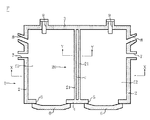
図1は、本発明における一形態の金属溶解炉(金属溶湯用炉)Fを示す水平断面図、図2は、図1中のX−X線の矢視に沿った垂直断面図である。
金属溶解炉Fは、図1,図2に示すように、平面視がほぼ長方形で且つ全体がほぼ直方体を呈する炉本体1と、係る炉本体1の内部を図示で左右に2つの炉室f1,f2に分割する分割壁20と、を備えている。
炉本体1は、ベースB上に配設された鉄骨構造物16の上に構築され、耐火物から形成された左右一対の側壁2、背面壁3、正面壁4、天井12、および炉床14からなる。尚、炉本体1の上記各部分も、それらの外側ごとに配置された図示しない鉄骨構造物に支持されている。また、金属溶解炉Fは、炉内が単一の炉室であった炉本体1内を分割壁20によって二分割するよう改修したものである。
In the following, the best mode for carrying out the present invention will be described.
FIG. 1 is a horizontal sectional view showing a metal melting furnace (metal melting furnace) F according to an embodiment of the present invention, and FIG. 2 is a vertical sectional view taken along the line XX in FIG.
As shown in FIGS. 1 and 2, the metal melting furnace F has a furnace body 1 having a substantially rectangular shape in plan view and a substantially rectangular parallelepiped shape as a whole, and two furnace chambers f1 on the left and right sides of the interior of the furnace body 1 in the drawing. , F <b> 2 and a dividing
The furnace body 1 is constructed on a
図1,図2に示すように、炉本体1の正面壁4には、炉室f1,f2を開閉すための耐火・耐熱性のドア6が、左右に開口部5に、昇降可能して配置されている。また、各側壁2の上部には、前後一対ずつのバーナ用孔7,8が貫通して形成され、これらには図示しないバーナが挿入されている。更に、炉室f1,f2ごとの背面壁3と炉床14とにまたがって、溶解されたアルミニウムの溶湯Mを出湯させるための出湯口9が形成されている。
尚、上記ドア6は、炉室f1,f2内に原料の投入、脱滓、または溶湯の攪拌する際に用いるフォークリフト(図示せず)の先端部を出し入れするために開閉される。係るドア6および開口部5の底辺は、溶湯Mの湯面レベルよりも上方に設定されている。また、炉室f1,f2内で前記バーナから放射されて原料を加熱した燃焼ガスは、図示しない煙道を通じて、本溶解炉Fの外部に排出される。
As shown in FIGS. 1 and 2, the front wall 4 of the furnace body 1 is provided with a fire-resistant and heat-resistant door 6 for opening and closing the furnace chambers f1 and f2. Has been placed. Further, a pair of front and
The door 6 is opened and closed in order to put in and out the front end of a forklift (not shown) used when the raw materials are charged into the furnace chambers f1 and f2 and when the molten metal is stirred. The door 6 and the bottom of the opening 5 are set above the surface level of the molten metal M. Further, the combustion gas radiated from the burner in the furnace chambers f1 and f2 to heat the raw material is discharged outside the melting furnace F through a flue (not shown).
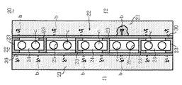
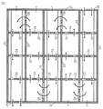
図3は、図1中のY−Y線の矢視に沿った分割壁20を示す垂直断面図、図4は、その構造体22を示し且つ図3の中央における垂直断面図、図5は、係る分割壁20の一部を省略した分解斜視図である。
分割壁20は、図3〜図5に示すように、対向する左右一対の耐火壁21と、係る耐火壁21,21間に位置し且つこれらを支持する構造体22と、係る構造体22の内部に形成される冷媒流路cと、を備えている。
耐火壁21は、例えば、アルミナなどを主成分とする耐火物からなる。係る耐火壁21は、図3中の破線または実線で示すボルトbを介して構造体22に支持されている。尚、耐火壁21のうち、炉室f1,f2の炉床14寄りの位置で且つ前記溶湯Mが接触する部位と、その他の部位とでは、上記アルミナなどの成分を相違させても良い。
FIG. 3 is a vertical sectional view showing the
As shown in FIGS. 3 to 5, the dividing
The
構造体22は、図3〜図5に示すように、横(水平)方向に沿って互いに平行に配置された断面がチャンネル形を呈する複数の鉄骨23と、これらの間に縦(垂直)方向に結合され且つ上記とほぼ同じ断面である複数の鉄骨24と、これらの鉄骨23,24の両側面にそれぞれ接合される複数の鉄板(金属板)30と、前後一対の端部板27と、を備えている。尚、係る端部板27の前側と後側とは、相対的な呼称である。
図3中の部分破断図と図5中の一点鎖線で囲った部分断面とで示すように、各鉄板30には、先端部をほぼY字形に開いた多数のボルトbの頭部分が固着されている。各ボルトbの先端部は、耐火壁21の内側面に対応して明けた多数の有底穴(図示せず)にセラミックなどの耐火物を含むペーストを介して挿入され、係るペーストを焼成することで、各鉄板30に耐火壁21が固定される。
As shown in FIGS. 3 to 5, the
As shown in the partial cutaway view in FIG. 3 and the partial cross section surrounded by the one-dot chain line in FIG. 5, the head portions of a large number of bolts b whose tips are opened in a substantially Y shape are fixed to each
図3〜図5に示すように、複数の鉄骨23,24は、互いに直交して格子状になるように、ボルト・ナットまたは溶接にて結合され、これらの間にはほぼ直方体の空間が複数形成される。また、鉄骨23,24と各端部板27との間にも、同様な空間が形成される。更に、鉄骨23,24の両側面には、隙間が生じないように複数の前記鉄板30がネジ止めまたは溶接付けされる。
尚、最下段の鉄骨23は、図示しない鉄製金物を介して、前記鉄骨構造物16の上に連結されている。また、各端部板27も、同様にして背面壁3や正面壁4の外側にそれぞれ位置する鉄骨構造物に連結されている。
As shown in FIGS. 3 to 5, the plurality of steel frames 23 and 24 are joined by bolts, nuts, or welding so as to form a lattice shape orthogonal to each other, and there are a plurality of substantially rectangular parallelepiped spaces between them. It is formed. A similar space is also formed between the steel frames 23 and 24 and the
The
図3〜図5に示すように、各鉄骨24における一対のフランジ間に挟まれた幅広のウェブには、上下一対の通し孔25が穿設され、上・下端を除く鉄骨23の前端または後端寄りの上記と同様なウェブには、通し孔26が垂直方向で交互に位置するように穿設されている。更に、後側の端部板27の下端寄りには、給気孔28が、前側の端部板27の上端寄りには、排気孔29が穿設されている。
上記給気孔28、通し孔25,26、排気孔29、およびこれらの間に位置する鉄骨23,24、各端部板27、各鉄板30に囲まれ且つ複数の屈曲部を含むた空間は、本発明における冷媒流路cを構成している。
尚、各耐火壁21と前記背面壁3、正面壁4、天井12、炉床14との間も、前記同様の耐火性ペーストが挿入され且つ焼成されている。
As shown in FIGS. 3 to 5, a pair of upper and lower through
A space surrounded by the
The same refractory paste as described above is inserted and fired between each
予め、本金属溶解炉Fには、給気孔28に連通する図示しない給気管に送風機が配設され、且つ排気孔29から外部に連通する排気管が配管されている。
図4中の矢印で示すように、上記給気管から送風機によって送給されたエア(冷媒)は、右(後)側の端部板27の給気孔28から最下段と直上の鉄骨23,23間を各鉄骨24の通し孔25を通じて左側にほぼ水平に流れる。左(前)側の端部板27に近付いたエアは、下から2段目の鉄骨23の通し孔26を通じて上昇しつつUターンした後、下から2段目と3段目との鉄骨23,23間を各鉄骨24の通し孔25を通じて右側にほぼ水平に流れる。同様にして、エアは、上下に隣接する鉄骨23,23間を各鉄骨24の通し孔25を通じて左右の何れかに流れ、通し孔26を通じて上昇しつつ複数の屈曲部をUターンするため、全体としてジグザグ状の冷媒流路cを通過する。
In the present metal melting furnace F, a blower is disposed in an air supply pipe (not shown) communicating with the
As indicated by the arrows in FIG. 4, the air (refrigerant) fed from the air supply pipe by the blower is the steel frames 23, 23 directly above and below the lowermost stage from the
合計4回のUターン(屈曲部)を含むジグザグ状の冷媒流路cを通過する間に、冷媒であるエアは、構造体22を構成する各鉄骨23,24、各端部板27、および各鉄板30を冷却する。係る冷却作用を果たす間に、当該エアは、逆に昇温された後、左(前)側の端部板27の排気孔29から外部に放出される。
このため、図1に示すように、炉室f1,f2で溶解されたアルミニウムの溶湯Mの熱が、分割壁20の各耐火壁21を介して、構造体22の各鉄骨23,24、各端部板27、および各鉄板30に伝熱されても、極く僅かの温度上昇に留められる。この結果、上記各鉄骨23,24の強度が低下しないため、鉄板30を介して、左右一対の耐火壁21を確実に支持することができる。
尚、前記送風機は、排気孔29に連通する排気管の途中に配置しても良い。
While passing through the zigzag refrigerant flow path c including a total of four U-turns (bent portions), the air that is the refrigerant is the steel frames 23 and 24, the
For this reason, as shown in FIG. 1, the heat of the molten aluminum M melted in the furnace chambers f1 and f2 passes through the
The blower may be disposed in the middle of the exhaust pipe communicating with the
以上のように、前記金属溶解炉Fによれば、炉本体1の内部が分割壁20によって2つの炉室f1,f2に分割されているため、例えば、図2に示すように、各炉室f1,f2ごとにアルミニウムの溶湯Mを所要量に応じて必要な時間に溶解し、別々に出湯口9から出湯させることができる。このため、多種少量生産にも自在に対応できるため、小ロット生産を容易に行える。
しかも、炉本体1の内部を炉室f1,f2に分割する分割壁20は、一対の耐火壁21の間に、冷媒流路cを内設する鉄骨構造の構造体22を有する。このため、各耐火壁21および鉄板30を介して溶湯Mの熱が伝熱されても、鉄骨23,24などは、冷媒であるエアにより常に冷却されているので、それらを含む構造体22の強度が低下しない。
As described above, according to the metal melting furnace F, since the interior of the furnace body 1 is divided into two furnace chambers f1 and f2 by the dividing
Moreover, the dividing
その結果、例えば、溶解中の溶湯Mを攪拌するため、前記ドア6を開放し、開口部5から挿入されたフォークリフトの先端部が分割壁20の耐火壁21に当たっても、その変形ないし損傷を防ぐか、極く軽微なものに抑制することができる。従って、前記金属溶解炉Fは、分割壁20が高い強度および優れた耐久性を有すると共に、単一の炉室の溶解炉から改修する際の改修コストも低減でき、且つ操業に伴うメンテナンスコストも抑制することができる。
尚、炉室f1,f2の各出湯口9から出湯された溶湯Mは、図示しない取り鍋に注下され、次工程の保持炉(金属溶湯用炉、図示せず)に送られ、再度所定温度帯まで加熱された後、係る保持炉を傾動し、隣接する鋳型に鋳造されることで、所定のインゴットやビレットなどに鋳造される。
また、分割壁20により炉本体1の内部が2つの炉室f1,f2に分割され前記金属溶解炉Fは、新たに構築する場合にも、容易に適用することができる。
As a result, for example, even when the door 6 is opened to stir the molten metal M being melted and the tip of the forklift inserted through the opening 5 hits the
The molten metal M discharged from the
Also, the interior of the furnace body 1 is divided into two furnace chambers f1 and f2 by the dividing
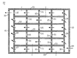
図6は、異なる形態の構造体32を示す前記図4と同様な垂直断面図である。
構造体32は、図6に示すように、前記同様の断面がチャンネル形を呈する複数の水平な鉄骨33と、これらの間に垂直に結合される上記とほぼ同じ断面である複数の鉄骨34と、係る鉄骨33,34の両側面にそれぞれ接合される前記鉄板30と、直方体で且つ中空部を有する前後一対のヘッダ40,41とからなる。
垂直な各鉄骨34には、通し孔35が穿設され、ヘッダ40,41の内側面にも複数の通し孔36,37が上下に隣接する鉄骨33,33間ごとに開口している。更に、図6で右側のヘッダ40における外側面の下部には、給気孔38が、左側のヘッダ41における外側面の上部には、排気孔39が穿設されている。尚、ヘッダ40,41も本発明の鉄骨に含まれる。
FIG. 6 is a vertical sectional view similar to FIG. 4 showing the
As shown in FIG. 6, the
Each
図6中の矢印で示すように、前記給気管から送風機によって送給されたエア(冷媒)は、右側のヘッダ40の給気孔38から各通し孔36を介して、各段の鉄骨33,33間を各鉄骨34の通し孔35を通じて左側にほぼ水平に並行して流れる。通し孔37から左側のヘッダ41内に入ったエアは、排気孔39から外部に排出するため、全体として水平な層流の冷媒流路cを通過する。
上記冷媒流路cを通過する間に、冷媒であるエアは、構造体32を構成する各鉄骨33,34、ヘッダ40,41、および各鉄板30を冷却する。エアが係る冷却作用を果たすことで、各鉄骨33,34などの強度が低下しないため、前記鉄板30を介して、左右の各耐火壁21を確実に支持することができる。従って、上記構造体32を含む分割壁を有する金属溶解炉Fにおいても、多種少量生産に容易に対応でき、耐火壁21の変形ないし損傷を防げ、高い強度および優れた耐久性を発揮できると共に、メンテナンスも低減できる。
尚、一対のヘッダを最上部と最下部とにそれぞれ水平に配置し、これらの間の垂直な鉄骨同士の間に垂直な冷媒流路cを平行に複数有するようにした形態、即ち、図6の構造体32を左右の何れかに90度回転させた構造体にしても良い。
As indicated by the arrows in FIG. 6, the air (refrigerant) fed from the air supply pipe by the blower passes from the
While passing through the refrigerant flow path c, the air as the refrigerant cools the steel frames 33 and 34, the
It should be noted that a pair of headers are horizontally arranged at the uppermost part and the lowermost part, respectively, and a plurality of vertical coolant channels c are provided in parallel between the vertical steel frames between them, that is, FIG. The
図7は、更に異なる形態の構造体42を示す垂直断面図である。
構造体42は、図7に示すように、前記同様の断面がチャンネル形を呈する複数の水平な鉄骨43,46と、これらの間に垂直に結合される上記とほぼ同じ断面である複数の鉄骨44と、係る鉄骨43,44,46の両側面にそれぞれ接合される前記鉄板30と、左右の端部板50,51とからなる。
最上段および最下段の鉄骨43を除く水平な各鉄骨46には、それぞれ通し孔47が穿設され、垂直な各鉄骨44には、その上端または下端付近に通し孔45が穿設されている。また、図7で右側の端部板50の下端付近には、給気孔48が、左側の端部板51の上端付近には、排気孔49が穿設されている。
FIG. 7 is a vertical cross-sectional view showing the
As shown in FIG. 7, the
Each
図7中の矢印で示すように、前記給気管から送風機によって送給されたエア(冷媒)は、右側の端部板50の給気孔48から係る端部板50と右端の鉄骨44との間を、各鉄骨46の通し孔47を通じて上昇し、最上段の鉄骨43とその直下の鉄骨46との間の通し孔45を含む屈曲部をUターンする。係るエアは、図7で右端の鉄骨44とその左側の鉄骨44との間を、各鉄骨46の通し孔47を下降し、最下段の鉄骨43とその直上の鉄骨46との間の通し孔45を含む屈曲部をUターンする。同様にして、エアは、左右に隣接する鉄骨44,44間における各鉄骨46の通し孔47を通じて左右に流れ、上・下端の各通し孔45を含む屈曲部を通じてUターンするため、全体としてジグザグ状の冷媒流路cを通過する。
As shown by the arrows in FIG. 7, the air (refrigerant) fed from the air supply pipe by the blower is between the
上記冷媒流路cを通過する間に、冷媒であるエアは、構造体42を構成する各鉄骨43,44,46、端部板50,51、および各鉄板30を冷却する。係るエアが係る冷却作用を果たすことで、各鉄骨44,46などの強度が低下しないため、前記鉄板30を介して、左右の各耐火壁21を確実に支持することができる。従って、上記構造体42を含む分割壁を有する金属溶解炉Fによっても、多種少量生産に容易に対応でき、耐火壁の変形ないし損傷を防げ、高い強度および優れた耐久性を発揮できると共に、メンテナンスおよびそのコストも低減できる。
While passing through the refrigerant flow path c, the air that is the refrigerant cools the steel frames 43, 44, 46, the
本発明は、以上において説明した各形態に限定されるものではない。
例えば、炉本体の内部を複数の分割壁により、3以上の炉室に分割しても良い。
また、前記炉室f1,f2を有する炉本体1を、鋳型に注湯するための金属溶湯保持炉として活用しても良い。この場合、炉本体1は、傾動可能とされる。
更に、前記溶解炉Fの炉室f1,f2の一方の炉床14を、他方の炉床14よりも高く施工し、高い炉床14の炉室を溶解炉とし、低い炉床14の炉室を保持炉とする複合形態の金属溶湯用炉としても良い。この場合、溶解炉の炉室の出湯口から出湯する溶湯は、炉本体の外側を迂回する耐火物製の樋を経て、保持炉の炉室内に注湯するようにすることもできる。
加えて、構造体は、複数の角形鋼管を平行に接合して構成し、それらの各端部寄りに通し孔を穿設することで、内部にジグザグ状の冷媒流路を有する箱形構造体としても良い。この場合、耐火壁は、当該構造体の両側面に露出する各鋼管に前記ボルトbを介して直に固定することにより、前記鉄板(金属板)を省略することも可能である。
尚、本発明の金属溶湯用炉は、アルミニウム以外の金属や合金にも適用できる。
The present invention is not limited to the embodiments described above.
For example, the interior of the furnace body may be divided into three or more furnace chambers by a plurality of dividing walls.
Moreover, you may utilize the furnace main body 1 which has the said furnace chambers f1 and f2 as a molten metal holding furnace for pouring into a casting_mold | template. In this case, the furnace body 1 can be tilted.
Further, one
In addition, the structure is formed by joining a plurality of rectangular steel pipes in parallel, and by forming a through hole near each end thereof, a box-shaped structure having a zigzag-like refrigerant flow path therein. It is also good. In this case, it is possible to omit the iron plate (metal plate) by fixing the fire wall directly to each steel pipe exposed on both side surfaces of the structure via the bolt b.
The molten metal furnace of the present invention can also be applied to metals and alloys other than aluminum.
F……………………………………………金属溶解炉(金属溶湯用炉)
M……………………………………………アルミニウムの溶湯(金属溶湯)
1……………………………………………炉本体
20…………………………………………分割壁
21…………………………………………耐火壁
22,32,42……………………………構造体
23,24,33,34,44,46………鉄骨
25,26,35,36,37,45,47…通し孔
30…………………………………………鉄板(金属板)
c……………………………………………冷媒流路
F …………………………………………… Metal melting furnace (metal melting furnace)
M …………………………………………… Aluminum melt (metal melt)
1 ……………………………………………
c …………………………………………… Refrigerant flow path
Claims (3)
炉本体の内部を分割壁により複数の炉室に分割しており、
上記分割壁は、一対の対向する耐火壁と、係る一対の耐火壁の間に位置し且つ当該耐火壁を支持する構造体と、係る構造体の内部に形成される冷媒流路と、を備え、
上記分割壁の構造体は、縦・横方向に沿って格子状に結合した鉄骨と、係る鉄鋼の両側面にそれぞれ接合され且つ前記耐火壁を固定する金属板と、を含むと共に、
上記冷媒流路は、少なくとも上記鉄骨と金属板とに囲まれた空間と、前記鉄骨の何れかに明けた通し孔とにより構成されている、
ことを特徴とする金属溶湯用炉。 A furnace for melting metal or holding molten metal,
The interior of the furnace body is divided into multiple furnace chambers by dividing walls,
The dividing wall includes a pair of opposed fire walls, a structure that is located between the pair of fire walls and supports the fire wall, and a refrigerant channel formed inside the structure. e,
The structure of the partition wall includes a steel frame coupled in a lattice shape along the vertical and horizontal directions, and a metal plate that is bonded to both side surfaces of the steel and fixes the fire wall, respectively .
The refrigerant flow path is configured by a space surrounded by at least the steel frame and the metal plate, and a through hole opened in any of the steel frames .
A molten metal furnace characterized by that.
ことを特徴とする請求項1に記載の金属溶湯用炉。 Before SL coolant channel, in the space surrounded by the said steel and the metal plate, and has a bent portion U-turn at least one location or more,
The furnace for molten metal according to claim 1.
ことを特徴とする請求項1または2に記載の金属溶湯用炉。 The coolant flow path passes in a zigzag manner through a through hole opened in one of the steel frames and a space surrounded by the steel frame and the metal plate .
The furnace for molten metal according to claim 1 or 2, characterized in that:
Priority Applications (1)
| Application Number | Priority Date | Filing Date | Title |
|---|---|---|---|
| JP2005315594A JP4983000B2 (en) | 2005-10-31 | 2005-10-31 | Metal melt furnace |
Applications Claiming Priority (1)
| Application Number | Priority Date | Filing Date | Title |
|---|---|---|---|
| JP2005315594A JP4983000B2 (en) | 2005-10-31 | 2005-10-31 | Metal melt furnace |
Publications (2)
| Publication Number | Publication Date |
|---|---|
| JP2007120892A JP2007120892A (en) | 2007-05-17 |
| JP4983000B2 true JP4983000B2 (en) | 2012-07-25 |
Family
ID=38144930
Family Applications (1)
| Application Number | Title | Priority Date | Filing Date |
|---|---|---|---|
| JP2005315594A Expired - Fee Related JP4983000B2 (en) | 2005-10-31 | 2005-10-31 | Metal melt furnace |
Country Status (1)
| Country | Link |
|---|---|
| JP (1) | JP4983000B2 (en) |
Family Cites Families (3)
| Publication number | Priority date | Publication date | Assignee | Title |
|---|---|---|---|---|
| JPS62108792U (en) * | 1985-12-26 | 1987-07-11 | ||
| JP2917515B2 (en) * | 1990-11-30 | 1999-07-12 | 神鋼電機株式会社 | Method and apparatus for preventing melting of furnace wall of cold crucible melting furnace |
| JPH1025526A (en) * | 1996-07-12 | 1998-01-27 | Miyamoto Kogyosho:Kk | Aluminum melting furnace |
-
2005
- 2005-10-31 JP JP2005315594A patent/JP4983000B2/en not_active Expired - Fee Related
Also Published As
| Publication number | Publication date |
|---|---|
| JP2007120892A (en) | 2007-05-17 |
Similar Documents
| Publication | Publication Date | Title |
|---|---|---|
| US4221922A (en) | Water cooled panel used in an electric furnace | |
| US6244197B1 (en) | Thermal induced cooling of industrial furnace components | |
| US10760854B2 (en) | Adjustable heat exchange apparatus and method of use | |
| JP3855133B2 (en) | Cooling plate for upright furnace | |
| EP1756320A4 (en) | HEAT EXCHANGER SYSTEM FOR USE IN THE MANUFACTURE OF STEEL | |
| JP4762172B2 (en) | Furnace body water cooling structure of flash furnace | |
| AU761359B2 (en) | Casting mould for manufacturing a cooling element and cooling element made in said mould | |
| JPH11217609A (en) | Cooling element for vertical furnace | |
| FI126540B (en) | Blast furnace for metallurgical processes | |
| JP4983000B2 (en) | Metal melt furnace | |
| ES2981245T3 (en) | Top loading roof for electric arc furnaces, metallurgical or refining furnaces and system thereof | |
| US6137823A (en) | Bi-metal panel for electric arc furnace | |
| CN1373814A (en) | Copper cooling plates for metallurgical furnaces | |
| RU2003133461A (en) | COOLING ELEMENT FOR COOLING A METALLURGICAL FURNACE | |
| CN1188650C (en) | Method and device for operating electric arc furnaces and/or resistance furnaces | |
| RU2264590C2 (en) | Cooling battery for well furnaces | |
| JP2023548367A (en) | Multi-semi-tube heat exchange system for electric arc, metallurgy or smelting furnace and its system | |
| JP4187752B2 (en) | Furnace body water cooling structure of flash furnace | |
| JP7042850B2 (en) | Upper shell system for cassette-type dropout boxes, combustion chambers, ducts and electric arc furnaces | |
| CA1150503A (en) | Furnace installation, more particularly for smelting ore concentrate | |
| US4358094A (en) | Furnace system for smelting ore concentrate and the like | |
| CZ310124B6 (en) | An equipment for metal smelting | |
| CN211717137U (en) | Novel reverberatory furnace top | |
| US20040256772A1 (en) | Cooling plate comprising a reinforcement element | |
| CN212585498U (en) | Novel furnace body cooling module |
Legal Events
| Date | Code | Title | Description |
|---|---|---|---|
| A621 | Written request for application examination |
Free format text: JAPANESE INTERMEDIATE CODE: A621 Effective date: 20080729 |
|
| A977 | Report on retrieval |
Free format text: JAPANESE INTERMEDIATE CODE: A971007 Effective date: 20110421 |
|
| A131 | Notification of reasons for refusal |
Free format text: JAPANESE INTERMEDIATE CODE: A131 Effective date: 20110517 |
|
| A521 | Written amendment |
Free format text: JAPANESE INTERMEDIATE CODE: A523 Effective date: 20110614 |
|
| TRDD | Decision of grant or rejection written | ||
| A01 | Written decision to grant a patent or to grant a registration (utility model) |
Free format text: JAPANESE INTERMEDIATE CODE: A01 Effective date: 20120327 |
|
| A01 | Written decision to grant a patent or to grant a registration (utility model) |
Free format text: JAPANESE INTERMEDIATE CODE: A01 |
|
| A61 | First payment of annual fees (during grant procedure) |
Free format text: JAPANESE INTERMEDIATE CODE: A61 Effective date: 20120409 |
|
| R150 | Certificate of patent or registration of utility model |
Free format text: JAPANESE INTERMEDIATE CODE: R150 |
|
| FPAY | Renewal fee payment (event date is renewal date of database) |
Free format text: PAYMENT UNTIL: 20150511 Year of fee payment: 3 |
|
| LAPS | Cancellation because of no payment of annual fees |