JP4982278B2 - Dimming sensor - Google Patents
Dimming sensor Download PDFInfo
- Publication number
- JP4982278B2 JP4982278B2 JP2007183617A JP2007183617A JP4982278B2 JP 4982278 B2 JP4982278 B2 JP 4982278B2 JP 2007183617 A JP2007183617 A JP 2007183617A JP 2007183617 A JP2007183617 A JP 2007183617A JP 4982278 B2 JP4982278 B2 JP 4982278B2
- Authority
- JP
- Japan
- Prior art keywords
- light
- unit
- light projecting
- signal
- projecting
- Prior art date
- Legal status (The legal status is an assumption and is not a legal conclusion. Google has not performed a legal analysis and makes no representation as to the accuracy of the status listed.)
- Expired - Fee Related
Links
- 238000000034 method Methods 0.000 claims description 30
- 238000012544 monitoring process Methods 0.000 claims description 28
- 238000003199 nucleic acid amplification method Methods 0.000 description 66
- 230000003321 amplification Effects 0.000 description 65
- 230000003287 optical effect Effects 0.000 description 42
- 230000008569 process Effects 0.000 description 25
- 239000000779 smoke Substances 0.000 description 15
- 238000012545 processing Methods 0.000 description 14
- 238000009826 distribution Methods 0.000 description 12
- 238000009434 installation Methods 0.000 description 11
- 230000000694 effects Effects 0.000 description 9
- 238000000926 separation method Methods 0.000 description 9
- 238000010586 diagram Methods 0.000 description 7
- 230000004048 modification Effects 0.000 description 4
- 238000012986 modification Methods 0.000 description 4
- 238000003860 storage Methods 0.000 description 4
- 230000002238 attenuated effect Effects 0.000 description 3
- 230000004913 activation Effects 0.000 description 2
- 230000006872 improvement Effects 0.000 description 2
- 230000004044 response Effects 0.000 description 2
- 230000005856 abnormality Effects 0.000 description 1
- NIXOWILDQLNWCW-UHFFFAOYSA-N acrylic acid group Chemical group C(C=C)(=O)O NIXOWILDQLNWCW-UHFFFAOYSA-N 0.000 description 1
- 230000004075 alteration Effects 0.000 description 1
- 230000008901 benefit Effects 0.000 description 1
- 239000003086 colorant Substances 0.000 description 1
- 238000011109 contamination Methods 0.000 description 1
- 238000012937 correction Methods 0.000 description 1
- 230000006866 deterioration Effects 0.000 description 1
- 239000004973 liquid crystal related substance Substances 0.000 description 1
- 238000004519 manufacturing process Methods 0.000 description 1
- 230000000644 propagated effect Effects 0.000 description 1
- 230000001902 propagating effect Effects 0.000 description 1
- 238000003908 quality control method Methods 0.000 description 1
- 239000011347 resin Substances 0.000 description 1
- 229920005989 resin Polymers 0.000 description 1
- 229920006395 saturated elastomer Polymers 0.000 description 1
Images


Landscapes
- Fire-Detection Mechanisms (AREA)
Description
本発明は、投光手段から投光され監視領域である空間を通過して受光手段に到達した光の減衰を検出し、火災等に起因する煙の存在を感知する減光式感知器に関する。 The present invention relates to a light-reducing sensor that detects the attenuation of light that has been projected from a light projecting unit and passed through a space serving as a monitoring area and reached a light receiving unit, and senses the presence of smoke caused by fire or the like.
従来から、火災の発生を検知するために、火災に伴って発生する煙を検出する煙感知器が用いられている。煙を検出する方法の一つとして、光(例えば近赤外線)が煙を通過した際の光強度の減衰を検出する方法があり、当該方法を利用する感知器は減光式感知器と呼ばれている。減光式感知器としては、一つの受光部と一つの投光部とを備え信号光を投受光する投受光部と、投受光部から投光された信号光を投受光部に向けて反射する反射板とが、それぞれ壁面上に対向配置され、投受光部と反射板とに挟まれた領域を監視領域とする減光式反射型感知器がある。また、信号光を投光する投光部と、投光部に対して対向配置され信号光を受光する受光部とを一つずつ備え、投光部と受光部とに挟まれた領域を監視領域とする減光式分離型感知器も用いられている。これらの減光式感知器における監視領域に煙が介入した場合、信号光が投光部から投光され受光部に受光されるまでの経路中に煙が存在するため、当該受光部における受光強度が減少し、これに基づいて火災発生が検出される(例えば、特許文献1参照)。 Conventionally, in order to detect the occurrence of a fire, a smoke detector that detects smoke generated with the fire has been used. One method of detecting smoke is to detect the attenuation of light intensity when light (for example, near-infrared rays) passes through the smoke. Sensors that use this method are called dimming sensors. ing. The dimming sensor includes a light receiving unit and a light projecting unit. The light projecting / receiving unit projects and receives signal light, and the signal light projected from the light projecting / receiving unit is reflected toward the light projecting / receiving unit. There is a dimming reflection type detector in which a reflecting plate is disposed opposite to each other on a wall surface, and a region sandwiched between the light projecting / receiving unit and the reflecting plate is a monitoring region. In addition, a light projecting unit that projects signal light and a light receiving unit that is disposed opposite to the light projecting unit and that receives signal light are provided one by one, and the area sandwiched between the light projecting unit and the light receiving unit is monitored. A dimming separation type sensor as a region is also used. When smoke intervenes in the monitoring area of these light-reducing detectors, the smoke is present in the path from when the signal light is projected from the light projecting unit and received by the light receiving unit. And the occurrence of fire is detected based on this (see, for example, Patent Document 1).
ところで、減光式感知器の適用範囲を広げるため、最大監視距離の拡大が要求されていたが、監視距離の増大に伴う信号光の減衰が制約となっていた。投光部から投光された信号光は拡散しながら監視領域を伝播するため、当該信号光の光パワー密度は、伝播光路長の2乗に反比例して減衰する。すなわち、伝播光路長をL、投受光部から投光された時点での光パワー密度をD0、Lの距離を伝播した時点での信号光の光パワー密度をD1、所定の比例定数をαとすると、D1=α×D0/L2となる。本式によれば、例えば、投光部から射出され100mの距離を伝播した信号光の光パワー密度は、投光部から1mの距離を伝播した時点での光パワー密度の1/10000まで減衰している。 By the way, in order to expand the application range of the dimming sensor, the maximum monitoring distance is required to be increased. However, the attenuation of the signal light accompanying the increase in the monitoring distance is a limitation. Since the signal light projected from the light projecting unit propagates through the monitoring region while diffusing, the optical power density of the signal light attenuates in inverse proportion to the square of the propagation optical path length. That is, the propagation optical path length is L, the optical power density at the time of projection from the light projecting / receiving unit is D0, the optical power density of the signal light at the time of propagation of the distance L is D1, and the predetermined proportionality constant is α. Then, the D1 = α × D0 / L 2 . According to this formula, for example, the optical power density of the signal light emitted from the light projecting unit and propagated a distance of 100 m is attenuated to 1/10000 of the optical power density at the time of propagating a distance of 1 m from the light projecting unit. is doing.
また、減光式反射型感知器では、投受光部と反射板との間を信号光が往復する必要がある。投受光部と反射板との間隔(監視距離)をL2、投受光部から投光された時点での光パワー密度をD0、投受光部から投光され反射板に到達した時点での信号光の光パワー密度をD1、反射板に反射され投受光部に到達した時点での信号光の光パワー密度をD2、所定の比例定数をβとした場合、D2=β×{α×(D0/L22)}/L22=α×β×D0/L24となる。つまり、全体としては投受光部と反射板との設置間隔(監視距離)の4乗に反比例して光パワー密度が減衰することになる。 Further, in the dimming reflection type detector, the signal light needs to reciprocate between the light projecting / receiving unit and the reflecting plate. The distance (monitoring distance) between the light projecting / receiving unit and the reflecting plate is L2, the optical power density at the time when the light is projected from the light projecting / receiving unit is D0, and the signal light when the light is projected from the light projecting / receiving unit and reaches the reflecting plate Is D1, the optical power density of the signal light when it is reflected by the reflector and reaches the light projecting and receiving unit is D2, and the predetermined proportionality constant is β, D2 = β × {α × (D0 / L2 2 )} / L2 2 = α × β × D0 / L2 4 . That is, as a whole, the optical power density is attenuated in inverse proportion to the fourth power of the installation interval (monitoring distance) between the light projecting / receiving unit and the reflecting plate.
このように、減光式感知器における監視距離を増大させた場合、すなわち、信号光の伝播光路長を増大させた場合、投光部から投光された信号光の光パワー密度は受光部に到達した時点では大きく減衰していることになり、感知器としてのS/N比が大幅に悪化するという問題点があった。 As described above, when the monitoring distance in the dimming sensor is increased, that is, when the propagation path length of the signal light is increased, the optical power density of the signal light projected from the light projecting unit is given to the light receiving unit. At the time of arrival, it is greatly attenuated, and the S / N ratio as a sensor is greatly deteriorated.
上述のように減光式感知器の最大監視距離の拡大要求があり、特に減光式反射型感知器は、減光式分離型感知器では必要となる投光部と受光部とを接続する配線が不要であるなど減光式分離型感知器に比べて大空間への適用の際の設置施工上のメリットが大きいことから、最大監視距離の拡大要求が一層強くなっている。しかし、反射型であるため信号光の伝播光路長は同じ距離を監視する減光式分離型感知器の2倍であることから、同等相当の投光性能では、減光式反射型感知器の最大監視距離は減光式分離型感知器に比べてどうしても短くなっていた。例えば、従来の減光式分離型感知器の最大監視距離は100m程度であるのに対し、同等相当の投光性能を有する減光式反射型感知器では30m程度であった。このような最大監視距離の拡大要求に対して、減光式反射型感知器に於いて単に従来のまま監視距離を増大させた場合には、S/N比が一層低下するため、改善が要望されていた。 As described above, there is a demand for extending the maximum monitoring distance of the dimming sensor. In particular, the dimming reflection type sensor connects the light projecting unit and the light receiving unit, which are necessary for the dimming separation type sensor. Compared to the dimming sensor, which requires no wiring, there is a greater advantage in installation work when applied to large spaces, and there is an increasing demand for an increase in the maximum monitoring distance. However, because of the reflection type, the propagation path length of the signal light is twice that of the dimming separation type sensor that monitors the same distance. The maximum monitoring distance was inevitably shorter than the dimming separation type sensor. For example, the maximum monitoring distance of the conventional dimming type separation type sensor is about 100 m, whereas the dimming type reflection type sensor having equivalent light projection performance is about 30 m. In response to such a request to increase the maximum monitoring distance, if the monitoring distance is simply increased as it is in the past in a dimming reflection type sensor, the S / N ratio will be further lowered, so improvement is desired. It had been.
これに対して、単純に受光部での信号増幅度を大きくすることで対応した場合、外乱光等に起因するノイズ成分も同時に増幅することとなり、増幅回路の動作も不安定となるなど、S/N比の悪化を避けることは困難であった。 On the other hand, when dealing with simply increasing the signal amplification degree at the light receiving unit, noise components caused by disturbance light or the like are simultaneously amplified, and the operation of the amplifier circuit becomes unstable. It was difficult to avoid deterioration of the / N ratio.
また、光学的な側面からの対応としては、投光部において大口径の投光レンズ(一般にアクリルなどの樹脂製)を使用し、光源(一般に近赤外LED)と投光レンズとの間隔を大きくする(焦点距離を長くする)ことで投光部から投光された光の光パワー密度(投光効率)を増大させることができる。しかし、減光式感知器のサイズ、特に奥行き寸法が大きくなるため、減光式感知器の設置に関して大きな制約が生じていた。また、投光レンズを大口径化するに従って投光レンズ有効径外周部の収差が大きくなる等の影響も生じてくるため、光パワー密度の増大には限界があった。さらに、投光レンズを大口径化しても、投光部に供給されているパワーを超えるパワーを有する信号光を投光部から投光させることは不可能であり、一つの光源が発している以上のエネルギーを取り出すことはそもそも出来ない。受光増幅度を所定範囲に抑えつつ監視距離を伸ばし、そのうえ良好なS/N比を獲得するには、従来にない抜本的な対応策が必要であった。なお、レンズの大口径化には、製造管理上及び品質管理上の難易度が増すといった問題点もある。 Also, as a countermeasure from the optical side, a large-diameter projection lens (generally made of resin such as acrylic) is used in the projection unit, and the distance between the light source (generally a near infrared LED) and the projection lens is set. By enlarging (increasing the focal length), it is possible to increase the optical power density (light projection efficiency) of the light projected from the light projecting unit. However, since the size of the dimming sensor, particularly the depth dimension, is large, there are significant restrictions on the installation of the dimming sensor. In addition, there is a limit to the increase in the optical power density because the larger the diameter of the projection lens, the greater the aberration of the outer periphery of the effective diameter of the projection lens. Furthermore, even if the projection lens has a large diameter, it is impossible to project signal light having power exceeding the power supplied to the projection unit from the projection unit, and one light source emits light. The above energy cannot be extracted in the first place. In order to extend the monitoring distance while keeping the light reception amplification level within a predetermined range, and to obtain a good S / N ratio, a drastic countermeasure that has not been taken until now has been required. In addition, there exists a problem that the difficulty in manufacturing management and quality control increases in enlargement of a lens.
また、減光式反射型感知器において、入射した光が入射方向に反射されるいわゆる再帰反射板が用いられている場合、当該反射板によって反射され投受光部に到達した信号光は投光部をピーク中心とする光パワー密度の分布を有している。従って、投光レンズを大口径化した場合、投光部と受光部との間隔(投光軸と受光軸との距離)も大きくなるため、受光部が光パワー密度分布のピークから離れてしまったり、受光レンズの一部にしか光が入射しなくなったりする問題が生じていた。このため、従来は、減光式感知器の最大監視距離の拡大要求に対して、S/N比を向上させる有効な方法がなかった。 In addition, when a so-called retroreflecting plate that reflects incident light in the incident direction is used in the dimming reflection type detector, the signal light reflected by the reflecting plate and reaching the light projecting / receiving unit is transmitted to the light projecting unit. Has a distribution of optical power density with the peak center. Therefore, when the diameter of the light projecting lens is increased, the distance between the light projecting part and the light receiving part (the distance between the light projecting axis and the light receiving axis) also increases, so that the light receiving part is separated from the peak of the optical power density distribution. There has been a problem that light is incident only on a part of the light receiving lens. For this reason, conventionally, there has been no effective method for improving the S / N ratio in response to a request for increasing the maximum monitoring distance of the dimming sensor.
本発明は、上記に鑑みてなされたものであって、減光式感知器の奥行き寸法を大きくすることなく、投光部から投光された信号光の光パワー密度を効率的に向上し、S/N比を大幅に改善した減光式感知器を提供することを目的とする。 The present invention has been made in view of the above, and without increasing the depth dimension of the dimming sensor, efficiently improves the optical power density of the signal light projected from the light projecting unit, An object of the present invention is to provide a dimming sensor having a significantly improved S / N ratio.
上述した課題を解決し、目的を達成するために、請求項1に記載の減光式感知器は、監視領域に対して投光手段から投光された信号光を受光手段にて受光し、当該受光手段から出力された情報に基づいて前記監視領域における所定の監視対象の有無を判定する減光式感知器であって、一つの前記受光手段にて受光可能なように前記信号光を投光する、四つの前記投光手段と、前記受光手段と、前記信号光を投光する前記投光手段の数を設定する設定手段とを備え、前記四つの投光手段の各々と前記受光手段とを、各投光手段による前記信号光の投光方向と前記受光手段による前記信号光の受光方向とが相互に略平行になる向きで、相互に一体に固定し、前記四つの投光手段の各々によって投光された前記信号光であって、前記投光方向に対向して設置された反射手段によって反射された前記信号光を、前記受光手段にて受光可能としたことを特徴とする。
In order to solve the above-described problems and achieve the object, the light-reducing sensor according to
また、請求項2に記載の減光式感知器は、請求項1に記載の減光式感知器において、前記設定手段によって前記信号光を投光するように設定された前記投光手段の全てが、相互に直列に接続されていることを特徴とする。
The dimming sensor according to
また、請求項3に記載の減光式感知器は、請求項1に記載の減光式感知器において、前記設定手段によって前記信号光を投光するように設定された前記投光手段の一部が並列接続されていることを特徴とする。
Further, the dimming sensor according to
また、請求項4に記載の減光式感知器は、請求項1に記載の減光式感知器において、前記設定手段によって前記信号光を投光するように設定された前記投光手段の一部が相互に直列接続されて複数の系統を成し、該複数の系統がさらに並列接続されていることを特徴とする。 According to a fourth aspect of the present invention, the dimming sensor according to the first aspect of the present invention is the dimming sensor according to the first aspect, wherein the setting means is configured to project the signal light. The units are connected in series with each other to form a plurality of systems, and the plurality of systems are further connected in parallel .
また、請求項5に記載の減光式感知器は、請求項1から4のいずれか一項に記載の減光式感知器において、前記設定手段の動作を制御する制御手段を備え、前記制御手段は、前記受光手段から出力された情報に基づいて、前記信号光を投光する前記投光手段の数を前記設定手段に設定させることを特徴とする。
The dimming sensor according to
請求項1に記載の本発明によれば、複数の投光手段の各々から同時に投光された信号光は、受光手段に対して重なり合って照射される。従って、受光手段での信号光の光パワー密度を投光手段の数に比例して増大させることができ、S/N比を大幅に向上させることができる。また、各投光手段の大きさは従来の減光式感知器における投光手段と同等、若しくは小さいため、減光式感知器の奥行き寸法を従来の減光式感知器と同等、若しくは小さくすることができる。
また、本発明を減光式反射型感知器に適用することになり、投光手段から反射手段に向けて信号光を投光させ、反射手段によって反射された信号光を受光手段に受光させることができる。
また、受光手段での信号光の光パワー密度を、投光手段が一つの場合と比較しておよそ4倍にすることができ、S/N比を大幅に向上させることができる。
また、投光手段の発光電流の調整のみならず、投光手段の駆動数によっても当該投光手段から投光させた信号光を調整することができ、受光手段に対して適切な強度の信号光を照射させることができる。これにより、減光式感知器の設置条件に対応した幅広く且つ細やかな信号光の光パワー密度の調整が可能となる。
According to the first aspect of the present invention, the signal light simultaneously projected from each of the plurality of light projecting units is applied to the light receiving unit in an overlapping manner. Therefore, the optical power density of the signal light at the light receiving means can be increased in proportion to the number of light projecting means, and the S / N ratio can be greatly improved. In addition, since the size of each light projecting means is the same as or smaller than the light projecting means in the conventional light-reducing sensor, the depth dimension of the light-reducing sensor is equal to or smaller than that of the conventional light-reducing sensor. be able to.
Further, the present invention is applied to a dimming reflection type detector, and signal light is projected from the light projecting means toward the reflecting means, and the signal light reflected by the reflecting means is received by the light receiving means. Can do.
Further, the optical power density of the signal light at the light receiving means can be increased approximately four times as compared with the case where there is one light projecting means, and the S / N ratio can be greatly improved.
Further, not only the adjustment of the light emission current of the light projecting means, but also the signal light emitted from the light projecting means can be adjusted according to the number of driving of the light projecting means. Light can be irradiated. This makes it possible to adjust the light power density of the signal light widely and finely according to the installation conditions of the dimming sensor.
請求項2に記載の本発明によれば、複数の投光手段を駆動させた場合でも消費電流の増大を防止することができ、電力ロスを低減することができる。 According to the second aspect of the present invention, even when a plurality of light projecting means are driven, an increase in current consumption can be prevented and power loss can be reduced.
請求項3に記載の本発明によれば、電源電圧に制約がある場合においても、当該制約の範囲内で消費電流を低減し、電力ロスを低減することができる。 According to the third aspect of the present invention, even when the power supply voltage is limited, the current consumption can be reduced and the power loss can be reduced within the range of the limitation.
請求項5に記載の本発明によれば、投光手段の駆動数によって当該投光手段から投光させる信号光射出エネルギーを調整することができ、受光手段に対して適切な強度の信号光を照射させることができる。これにより、減光式感知器の設置条件(例えば、減光式反射型感知器における投光手段と反射板との距離等)に対応した幅広く且つ細やかな信号光射出エネルギーの調整が可能となる。 According to the fifth aspect of the present invention, the signal light emission energy projected from the light projecting unit can be adjusted by the number of driving of the light projecting unit, and the signal light having an appropriate intensity can be supplied to the light receiving unit. Can be irradiated. As a result, a wide and fine adjustment of the signal light emission energy corresponding to the installation conditions of the dimming sensor (for example, the distance between the light projecting means and the reflecting plate in the dimming reflective sensor, etc.) becomes possible. .
以下に添付図面を参照して、この発明に係る減光式感知器の各実施の形態を詳細に説明する。まず、〔I〕各実施の形態の基本的概念を説明した後、〔II〕各実施の形態の具体的内容について説明し、〔III〕最後に、各実施の形態に対する変形例について説明する。ただし、各実施の形態によって本発明が限定されるものではない。 Embodiments of the dimming sensor according to the present invention will be described below in detail with reference to the accompanying drawings. [I] First, the basic concept of each embodiment will be described, then [II] the specific contents of each embodiment will be described, and [III] Finally, modifications to each embodiment will be described. However, the present invention is not limited to each embodiment.
〔I〕各実施の形態の基本的概念
まず、各実施の形態に共通の基本的概念について説明する。各実施の形態に係る減光式感知器は、火災に伴って発生する煙の検出を目的とするものである。
[I] Basic concept of each embodiment First, a basic concept common to each embodiment will be described. The dimming sensor according to each embodiment is intended to detect smoke generated with a fire.
各実施の形態に係る減光式感知器の設置対象は任意であり、例えば、工場施設やビル等の大規模な建物内や地下街、あるいは、一般住宅の台所や寝室等の部屋にも設置することができる。 The dimming sensor according to each embodiment can be installed arbitrarily, for example, in a large-scale building such as a factory facility or a building, an underground shopping center, or a room such as a kitchen or bedroom in a general house. be able to.
各実施の形態に係る減光式感知器の特徴の一つは、概略的に、一つの受光手段にて受光可能なように前記信号光を投光する複数の投光手段を備えていることにある。複数の投光手段を駆動させた場合、駆動された投光手段から投光された信号光は、一つの受光手段に対して重畳するように同時に照射される。従って、一つの受光手段に対して設置されている投光手段の数に比例して当該受光手段での信号光の光パワー密度が向上されているので、S/N比を大幅に改善することができる。 One of the features of the dimming sensor according to each embodiment is that it includes a plurality of light projecting units that project the signal light so that the light can be received by one light receiving unit. It is in. When a plurality of light projecting means are driven, the signal light projected from the driven light projecting means is simultaneously irradiated so as to be superimposed on one light receiving means. Therefore, since the optical power density of the signal light at the light receiving means is improved in proportion to the number of light projecting means installed for one light receiving means, the S / N ratio is greatly improved. Can do.
〔II〕各実施の形態の具体的内容
次に、本発明に係る各実施の形態の具体的内容について説明する。
[II] Specific Contents of Each Embodiment Next, specific contents of each embodiment according to the present invention will be described.
〔実施の形態1〕
まず実施の形態1について説明する。この形態は、一つの受光手段にて受光可能なように信号光を投光する四つの投光手段を備えているとともに、増幅手段及び増幅度制御手段を備えている形態である。なお、本実施の形態1においては減光式反射型感知器を例として説明するが、同様の構成を減光式分離型感知器に適用することもできる。
[Embodiment 1]
First, the first embodiment will be described. This form is a form in which four light projecting means for projecting signal light are provided so that light can be received by one light receiving means, as well as an amplification means and an amplification degree control means. In the first embodiment, a dimming reflection type sensor will be described as an example, but the same configuration can be applied to a dimming type separation sensor.
(減光式感知器の構成)
まず、減光式感知器の構成を説明する。図1は実施の形態1に係る減光式感知器の斜視図、図2は減光式感知器の分解図、図3は減光式感知器の電気的構成を機能概念的に示すブロック図、図4はカバーおよびレンズカバーを取除いた減光式感知器の正面図である。
(Configuration of dimming sensor)
First, the configuration of the dimming sensor will be described. 1 is a perspective view of a dimming sensor according to
図1に示すように、減光式感知器1は、煙の発生を監視する対象となる領域において、反射板2と相互に対向して配置されている。減光式感知器1は、当該減光式感知器1から投光され反射板2で反射された信号光を受光し、その受光量を監視している。また、図2及び図3に示すように、減光式感知器1は基本構造体となる筐体10を有しており、この筐体10は、筐体本体10a、及び、筐体本体10aに対して着脱自在に取り付けられているカバー10bを備えている。また、筐体本体10aには、光学ユニット20、表示部30、記憶部40、及び、制御部50が搭載されている。
As shown in FIG. 1, the dimming
(減光式感知器の構成−光学ユニット)
光学ユニット20は、減光式感知器1における煙の検出に用いられる光学系の機器を相互一体にユニット化したもので、例えば、投光部21、受光部22、照準器23、及び、レンズカバー24を有している。
(Configuration of dimming sensor-optical unit)
The
投光部21は、煙の検出に用いられる信号光を反射板2に対して投光するためのものであり、特許請求の範囲における投光手段に対応している。具体的には、図4に示すように、本実施の形態1では、この投光部21として、第1の投光部21a、第2の投光部21b、第3の投光部21c、第4の投光部21dの合計四つの投光部21が光学ユニット20に設置されている。各投光部21のサイズは、従来の減光式感知器1における投光部と同等、若しくは小さい。また、各投光部21の構成は同一であることが望ましい。なお、投光部21の具体的な構成や、投光部21から投光される光の波長等は任意であるが、例えば、近赤外線を発するLED(Light Emitting Diode)210を光源とし、LED210で発せられた光をレンズ211で集光して投光させてもよい。
The
受光部22は、反射板2によって反射された信号光を受光するためのものであり、特許請求の範囲における受光手段に対応している。受光部22の具体的な構成は任意であるが、例えば、受光部22へ入射する信号光を集光させるレンズ220、レンズ220によって集光された信号光を電気信号に変換するフォトダイオード等の受光素子221、及び、受光素子221から出力された電気信号を増幅して受光信号として制御部50に出力する増幅部222を備えている。増幅部222は、特許請求の範囲における増幅手段に対応している。また、増幅部222は、後述する増幅度制御部53に制御され、受光素子221から出力される電気信号に対する増幅度を段階的に切替える。なお、増幅部222の具体的な構成は任意であり、例えば、増幅回路を複数段組み合わせて接続し、作動させる増幅回路を切替えることにより、増幅部222による増幅度を段階的に切替えることができる。
The
図3に戻り、照準器23は、減光式感知器1を設置する際に、投光部21から投光される信号光の照射領域の範囲内に反射板2が位置するように減光式感知器1の設置方向を定めるために用いられる。照準器23の具体的構成は任意であり、例えば、信号光の照射領域の形状と相似の形状をした照準孔230、及び覗き孔231をレンズカバー24上に設け、またミラー232を光学ユニット20上に設け、覗き孔231からミラー232を介して照準孔230内に位置する反射板2を視認するようにしても良い。ミラー232に映された照準孔230を覗き孔231から覗いた場合において、照準孔230の中心に反射板2が位置するように減光式感知器1の設置角度の調整を行うことで、投光部21から投光される信号光を反射板2に照射させることができる。なお図2で覗き孔231は板厚方向に対し、レンズカバー24を筐体本体10aに取り付けた状態で、ミラー232を通して照準孔230を見通せる角度、大きさに空けられている。
Returning to FIG. 3, the
レンズカバー24は、投光部21及び受光部22のレンズをカバーするためのものであり、投光部21及び受光部22のレンズの前方に配置されている。
The
なお、上述の投光部21、受光部22、及び、照準器23は、光学ユニット20上に相互に近接して固定されている。また、投光部21と受光部22とは、投光部21の投光方向と受光部22の受光方向とが一致するように相互に光軸を平行にして配置されている。また、各投光部21の配置は任意であるが、受光部22の受光軸を中心とした同一の円周上に各投光部21の投光軸が配置されることが望ましい。つまり、各投光部21が受光部と同一の間隔を隔てて配置されていることが望ましい。さらに、そのように配置されている投光部21同士が相互に同一の間隔を隔てて配置されていることが望ましい。
The
(減光式感知器の構成−表示部)
表示部30は、減光式感知器1の動作状態(例えば、監視状態、障害状態、火災状態等)を表示するためのものであり、制御部50によって制御される。表示部30の具体的な構成は任意であり、各状態に対応した色(例えば、監視状態:緑、障害状態:黄、火災状態:赤)で発光する複数のLEDを用いてもよく、あるいは、液晶表示装置を用いて文字表示をさせてもよい。また、上記の動作状態として、投光部21の駆動数、受光部22の受光量、受光増幅度、あるいは各種案内表示等を表示させることもできる。
(Configuration of dimming sensor-display section)
The
(減光式感知器の構成−記憶部)
記憶部40は、減光式感知器1における処理に供される情報、例えば、受光部22での受光強度の履歴や、光学部材の汚損補償等に関する内部補正の履歴等を記憶するためのものである。
(Configuration of dimming sensor-storage unit)
The
(減光式感知器の構成−制御部)
制御部50は、減光式感知器1における所定の処理を行うためのものである。制御部50は、図3に示すように、投光制御部51、受光制御部52、増幅度制御部53、及び、火災判定部54を備えている。
(Configuration of dimming sensor-control unit)
The
投光制御部51は、投光部21を制御するためのものであり、具体的には、投光部21におけるLED210等の光源を駆動させるタイミングや、投光部21に供給される発光電流の制御をおこなう。
The light projecting
受光制御部52は、受光部22を制御するためのものであり、具体的には、受光部22の受光素子221に受光を行わせるタイミング、あるいは、受光した信号光のサンプリングを行わせるタイミングや、受光素子221によって変換された電気信号の処理等を行う。
The light receiving control unit 52 is for controlling the
増幅度制御部53は、受光素子221から出力された電気信号に対する増幅部222による増幅度を制御するためのものであり、特許請求の範囲における増幅度制御手段に対応している。増幅度制御部53は、増幅部222による増幅度の制御を行うことで、受光部22から制御部50に入力される受光信号の入力レベルを所定の範囲内に調整する。
The amplification
火災判定部54は、信号光を受光した受光部22から受光制御部52を介して入力された信号に基づき、火災等の判定を行うものであり、特許請求の範囲における異常判定手段に対応している。
The
なお、制御部50の具体的構成は任意であるが、例えば、OS(Operating System)などの制御プログラム、各種の処理手順などを規定した組み込みプログラム、所要データを格納するための内部メモリ、及び、これらのプログラムを実行するCPU(Central Processing Unit)を備えて構成される。
The specific configuration of the
(反射板の構成)
反射板2は、投光部21から投光された信号光を反射するためのものであり、特許請求の範囲における反射手段に対応する。この反射板2は、信号光の投光方向と対向し、且つ、当該投光方向と当該反射板2の表面とが略直交するように設置されている。反射板2の具体的な構成は任意であるが、入射した光が入射方向に反射する再帰反射板を用いることが望ましい。これにより、光学ユニット20から反射板2に信号光を照射させた場合、信号光は反射板2によって確実に光学ユニット20に向けて反射され、投光部21に近接して設置されている受光部22にて受光することが可能となる。
(Structure of reflector)
The reflecting
(減光式感知器の動作)
次に、減光式感知器1の動作について説明する。図5は反射板2によって反射され受光部22に照射された信号光の照射分布を概念的に示した平面図である。
(Operation of dimming sensor)
Next, the operation of the dimming
受光部22の周囲に配置されている4つの投光部21から投光された信号光は、上述の再帰反射板によって、各々の信号光が投光された投光部21に向かって反射される。投光部21から反射板2へ向かう信号光は、図5に示すように、受光部22の周囲に配置された第1の投光部21a、第2の投光部21b、第3の投光部21c、第4の投光部21dから投光され、ある伝播距離に於いてそれぞれの投光部21の光軸を中心とするA、B、C、Dで示した照射分布を有している。ここで、上述のように、各投光部21の出力やサイズ等の構成を同一としているので、同時に照射された信号光の照射分布A、B、C、Dは相互に同一の大きさを有する略円形の領域となっている。また、各投光部21と受光部22との距離が同一であり、各投光部21は相互に同一の間隔を隔てて配置されているので、照射分布A、B、C、Dは受光部22を中心として相互に均一に重なり合っている。このように重なり合った照射分布の略中心部が反射板2に照射され、反射板2からの反射光が投光部21に近接して配置された受光部22へ入射することになる。
The signal light projected from the four light projecting
図6は図5のE−E’断面における信号光の強度分布を示したグラフである。図6に示すように、第1の投光部21a、第2の投光部21b、第3の投光部21c、第4の投光部21dから同時に投光された信号光は、それぞれの信号光が投光された投光部21の近傍をピークとする山型の強度分布を有しており、反射板2の近傍で重なり合っている。図6のように、各投光部21から同時に投光され反射板2に到達している信号光の強度は、各投光部21から投光された信号光が重なり合った結果、投光部が一つの場合の受光強度の約4倍の強度となっている。
FIG. 6 is a graph showing the intensity distribution of signal light in the E-E ′ cross section of FIG. 5. As shown in FIG. 6, the signal lights simultaneously projected from the first
(減光式感知器の動作−初期調整処理)
次に、減光式感知器1を設置する場合において、投光部21での出力や受光部22での増幅度を設置条件に対応して調整するための初期調整処理の流れについて説明する。具体的には、投光部21に供給される発光電流の制御、及び、増幅部222における増幅度の制御等が制御部50によって実行される。
(Operation of dimming sensor-initial adjustment process)
Next, the flow of the initial adjustment process for adjusting the output at the
まず、初期調整処理の概要について説明する。図7は、初期調整処理の概略的な流れを示したフローチャートである。照準器23を使用して投光部21及び受光部22の光軸を機械的に調整して固定した後、所定の起動操作によって減光式感知器1が起動されると、若しくは初期設定開始スイッチ等の操作が行われると、図7に示すように、投光制御部51は所定の発光電流を初期発光電流として各投光部21に通電させ、当該投光部21を駆動させる(ステップSA−1)。各投光部21から投光された信号光が反射板2によって反射され、受光部22によって受光されると、受光部22での信号光の受光強度に対応した受光信号が制御部50に入力される。このときの受光信号のレベルが所定の範囲内であった場合(ステップSA−2、Yes)、増幅度制御部53は増幅度を固定し、投光制御部51は発光電流調整処理を実行する(ステップSA−3)。また、受光信号のレベルが所定の範囲外であった場合には(ステップSA−2、No)、増幅度制御部53は受光増幅度調整処理を行い(ステップSA−4)、受光信号のレベルが所定の範囲内か否かを再度判断する(ステップSA−2)。
First, an outline of the initial adjustment process will be described. FIG. 7 is a flowchart showing a schematic flow of the initial adjustment process. After the optical axes of the
(減光式感知器の動作−発光電流調整処理)
次に、ステップSA−3における発光電流調整処理について説明する。図8は発光電流調整処理の流れを示したフローチャートである。図8に示すように、増幅度制御部53は、発光電流調整処理が開始された時点での増幅部222による増幅度を維持する(ステップSB−1)。そして、受光信号のレベルが所定値と許容差の範囲内で一致している場合(ステップSB−2、Yes)、投光制御部51は各投光部21に通電させている発光電流のレベルを維持する(ステップSB−3)。受光信号のレベルが許容差の範囲外であった場合には(ステップSB−2、No)、投光制御部51は各投光部21に通電させる発光電流を変化させ、受光信号のレベルが所定値と許容差の範囲内で一致するように調整する(ステップSB−4)。
(Operation of dimming sensor-Light emission current adjustment processing)
Next, the light emission current adjustment process in step SA-3 will be described. FIG. 8 is a flowchart showing the flow of light emission current adjustment processing. As shown in FIG. 8, the amplification
(減光式感知器の動作−受光増幅度調整処理)
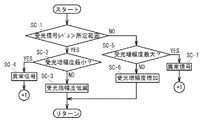
次に、ステップSA−4における受光増幅度調整処理について説明する。図9は受光増幅度調整処理の流れを示したフローチャートである。図9に示すように、受光信号のレベルが所定の範囲を超えている場合(ステップSC−1、Yes)、増幅度制御部53は増幅部222における増幅度が最小段階にあるか否かを確認する(ステップSC−2)。増幅度が最小段階ではない場合(ステップSC−2、No)、増幅度制御部53は増幅部222による増幅度を一段階低下させる(ステップSC−3)。増幅度が最小段階だった場合には(ステップSC−2、Yes)、増幅度制御部53は、光軸ずれや外乱光の入射等によって受光信号のレベルが飽和していると判定し、エラーを意味する信号を出力するとともに表示部30によってエラー表示をさせ(ステップSC−4)、初期調整処理を終了する。
(Operation of dimming sensor-received light gain adjustment processing)
Next, the received light amplification level adjustment process in step SA-4 will be described. FIG. 9 is a flowchart showing the flow of light reception amplification degree adjustment processing. As shown in FIG. 9, when the level of the received light signal exceeds the predetermined range (step SC-1, Yes), the amplification
一方、受光信号のレベルが所定の範囲を下回っている場合(ステップSC−1、No)、増幅度制御部53は増幅部222における増幅度が最大段階にあるか否かを確認する(ステップSC−5)。増幅度が最大段階ではない場合(ステップSC−5、No)、増幅度制御部53は増幅部222による増幅度を一段階増大させる(ステップSC−6)。増幅度が最大段階だった場合には(ステップSC−5、Yes)、増幅度制御部53は、光軸ずれ等によって受光信号のレベルが不足していると判定し、エラーを意味する信号を出力するとともに表示部30によってエラー表示をさせ(ステップSC−7)、初期調整処理を終了する。
On the other hand, when the level of the received light signal is below the predetermined range (step SC-1, No), the amplification
(実施の形態1の効果)
このように実施の形態1によれば、減光式感知器1は一つの受光部22に対して複数の投光部21を備えており、各投光部21から同時に投光された信号光は、反射板2に対して重なり合って照射される。従って、反射板2で反射され、受光部22に達する信号光の光パワー密度を投光部21の数に比例して増大させることができ、S/N比を大幅に向上させることができる。また、各投光部21の大きさは従来の減光式感知器における投光部と同等、若しくは小さいため、減光式感知器1の奥行き寸法を従来の減光式感知器と同等、若しくは小さくすることができる。
(Effect of Embodiment 1)
As described above, according to the first embodiment, the dimming
また、投光部21と受光部22とを相互に近接させると共に当該投光部21の投光方向と当該受光部22の受光方向とが一致するように配置し、さらに、投光部21の投光方向と対向するように反射板2を配置しているので、投光部21から反射板2に向けて信号光を投光させることにより、反射板2によって反射された信号光を受光部22に受光させることができる。
The
また、減光式感知器1は一つの受光部22に対して四つの投光部21を備えているので、受光部22での信号光の光パワー密度を、投光部21が一つの場合と比較しておよそ4倍にすることができ、S/N比を大幅に向上させることができる。
Further, since the dimming
また、各投光部21と受光部22との距離が同一であり、各投光部21は相互に同一の間隔を隔てて配置されているので、各投光部21から投光され反射板2に照射される信号光を、受光部22の受光軸(反射板2の略中央)を中心として相互に均一に重なり合わせることができ、反射板2で反射され受光部22で受光される信号光の光パワー密度を著しく向上させることができる。
In addition, since the distance between each light projecting
また、増幅度制御部53によって増幅部222を制御し、受光素子221から出力された電気信号に対する増幅度を調整しているので、減光式感知器1の設置条件に対応した適切な強度の受光信号に基づいて制御部50に火災判定等の処理を行わせることができる。
In addition, since the
〔実施の形態2〕
次に、実施の形態2について説明する。この形態は、設定手段を備えた形態である。
[Embodiment 2]
Next, a second embodiment will be described. This form is a form provided with setting means.
(減光式感知器の構成)
まず、減光式感知器の構成を説明する。図10は実施の形態2に係る減光式感知器の電気的構成を機能概念的に示すブロック図である。なお、実施の形態2の構成は、特記する場合を除いて実施の形態1の構成と略同一であり、実施の形態1の構成と略同一の構成についてはこの実施の形態1で用いたのと同一の符号及び/又は名称を必要に応じて付して、その説明を省略する。
(Configuration of dimming sensor)
First, the configuration of the dimming sensor will be described. FIG. 10 is a block diagram functionally conceptually showing the electrical configuration of the dimming sensor according to the second embodiment. The configuration of the second embodiment is substantially the same as the configuration of the first embodiment except where otherwise specified, and the same configuration as that of the first embodiment is used in the first embodiment. The same reference numerals and / or names are attached as necessary, and the description thereof is omitted.
(減光式感知器の構成−切替スイッチ)
図10に示すように、本実施の形態2に係る減光式感知器1は、切替スイッチ60を備えている。切替スイッチ60は、駆動させる投光部21の数を設定するためのものであり、特許請求の範囲における設定手段に対応している。切替スイッチ60の具体的な構成は任意であり、例えば、ディップスイッチ等を切替スイッチ60として用いることで、駆動させる投光部21の数を手動操作により切替えることができる。あるいは、制御部50と投光部21とを接続している電気回路に切替スイッチ60を組み込み、制御部50に対する受光部22からの入力に基づいて制御部50によって切替スイッチ60を制御させることもできる。
(Configuration of dimming sensor-changeover switch)
As shown in FIG. 10, the dimming
(減光式感知器の動作)
次に、減光式感知器1を設置する場合における初期調整処理の流れ、及び、当該初期調整処理の中で行われる切替スイッチ60による投光部21の駆動数切替処理の流れについて説明する。なお、上述の説明では切替スイッチ60を手動により操作することもできると説明しているが、以下では、切替スイッチ60が制御部50によって制御される場合について説明する。
(Operation of dimming sensor)
Next, the flow of the initial adjustment process when the dimming
(減光式感知器の動作−初期調整処理)
まず、初期調整処理の概要について説明する。図11は、初期調整処理の概略的な流れを示したフローチャートである。図11に示すように、所定の起動操作によって減光式感知器1が起動されると、若しくは初期設定開始スイッチ等の操作が行われると、投光制御部51は切替スイッチ60を制御し、第1の投光部21aのみを駆動可能とする(ステップSD−1)。続いて、投光制御部51は、所定の発光電流を初期発光電流として第1の投光部21aに通電させ、当該第1の投光部21aを駆動させる(ステップSD−2)。第1の投光部21aから投光された信号光が反射板2によって反射され、受光部22によって受光されると、受光部22での信号光の受光強度に対応した受光信号が制御部50に入力される。このときの受光信号のレベルが所定の範囲内であった場合(ステップSD−3、Yes)、増幅度制御部53は増幅度を固定し、投光制御部51は発光電流調整処理を実行する(ステップSD−4)。また、受光信号のレベルが所定の範囲外であった場合には(ステップSD−3、No)、増幅度制御部53及び投光制御部51によって増幅度調整・駆動数切替処理が実行され(ステップSD−5)、受光信号のレベルが所定の範囲内か否かが再度判断される(ステップSD−3)。
(Operation of dimming sensor-initial adjustment process)
First, an outline of the initial adjustment process will be described. FIG. 11 is a flowchart showing a schematic flow of the initial adjustment process. As shown in FIG. 11, when the dimming
(減光式感知器の動作−増幅度調整・駆動数切替処理)
次に、ステップSD−5における増幅度調整・駆動数切替処理について説明する。図12は、増幅度調整・駆動数切替処理の流れを示したフローチャートである。図12に示すように、ステップSE−1からステップSE−6までの処理は、実施の形態1で説明した受光増幅度調整処理におけるステップSC−1からステップSC−6までの処理と同様であるので、説明を省略する。ステップSE−5において、増幅部222による増幅度が最大段階だった場合には(ステップSE−5、Yes)、投光制御部51は投光部21の駆動数が最大かを確認する(ステップSE−7)。投光部21の駆動数が最大ではなかった場合(ステップSE−7、No)、投光制御部51は投光部21の駆動数を一つ増加させ(ステップSE−8)、増幅度制御部53は増幅部222による増幅度を初期値にリセットする(ステップSE−9)。投光部21の駆動数が最大であった場合(ステップSE−7、Yes)、投光制御部51は光軸ずれ等により受光信号のレベルが不足していると判定し、エラーを意味する信号を出力するとともに、表示部30によってエラー表示をさせ(ステップSE−10)、初期調整処理を終了する。
(Density sensor operation-amplification adjustment and drive number switching)
Next, the amplification degree adjustment / drive number switching process in step SD-5 will be described. FIG. 12 is a flowchart showing the flow of the amplification degree adjustment / drive number switching process. As shown in FIG. 12, the processing from step SE-1 to step SE-6 is the same as the processing from step SC-1 to step SC-6 in the received light gain adjustment processing described in the first embodiment. Therefore, explanation is omitted. In step SE-5, when the amplification degree by the amplifying
(実施の形態2の効果)
このように実施の形態2によれば、切替スイッチ60によって投光部21の駆動数を切替えることができる。従って、投光部21の発光電流の調整のみならず、投光部21の駆動数によっても当該投光部21から投光させる信号光射出エネルギーを調整することができ、受光部22に対して適切な強度の信号光を照射させることができる。これにより、実施の形態1における基本的な効果に加えて、減光式感知器1の設置条件(例えば、減光式反射型感知器における投光部21と反射板2との距離等)に対応した幅広く且つ細やかな信号光射出エネルギーの調整が可能となる。
(Effect of Embodiment 2)
As described above, according to the second embodiment, the drive number of the
〔実施の形態3〕
次に、実施の形態3について説明する。この形態は、投光手段を直列接続と並列接続とを組み合わせて接続した形態である。以下の説明では、投光手段の駆動数の設定手段としての切替スイッチについて具体的に示す。
[Embodiment 3]
Next,
(投光部21の回路構成)
まず、投光部21の回路構成を説明する。図13は実施の形態3に係る投光部21における駆動回路の概略を示した回路図であり、図13(a)は四つの投光部21が全て直列接続されている場合、図13(b)は四つの投光部21が直列接続と並列接続とを組み合わせて接続されている場合を示す図である。なお、実施の形態3の構成は、特記する場合を除いて実施の形態2の構成と略同一であり、実施の形態2の構成と略同一の構成についてはこの実施の形態2で用いたのと同一の符号及び/又は名称を必要に応じて付して、その説明を省略する。
(Circuit configuration of the light projecting unit 21)
First, the circuit configuration of the
上述のように、本発明に係る減光式感知器1は複数の投光部21を備えているため、回路構成によっては投光部21の駆動数の増大に伴って消費電流が大きく増加し、電力ロスが増加する場合がある。これに対して、消費電流値を抑制するためには、図13(a)に示すように、全ての投光部21を直列接続することが望ましい。図13(a)では、減光式感知器1は、四つの投光部21を直列接続した1系統の駆動回路を備えている。また、各投光部21をバイパスするように切替スイッチ60が設けられており、これらの切替スイッチ60のON/OFFを組み合わせることで投光部21の駆動数を任意に切替えることができる。
As described above, since the light-reducing
上述のように、消費電流の低減のためには全ての投光部21を直列接続することが望ましいが、全投光部21を駆動させた時の駆動電圧が、投光部21に対して電力を供給する電源の電圧を上回ってしまう場合もある。このような場合には、図13(b)に示すように、二つの投光部21を直列接続した駆動回路を、複数組(ここでは2系統)並列に接続した回路を構成することもできる。また、この回路は、投光部21をバイパスする切替スイッチ60と2系統の回路間を並列接続する切替スイッチ60とを備えており、これらの切替スイッチ60のON/OFFを組み合わせることで投光部21の駆動数を任意に切替えることができる。
As described above, in order to reduce current consumption, it is desirable to connect all the light projecting
(実施の形態3の効果)
このように実施の形態3によれば、全ての投光部21が直列接続されているので、実施の形態1における基本的な効果に加えて、複数の投光部21を駆動させた場合でも消費電流の増大を防止することができ、電力ロスを低減することができる。
(Effect of Embodiment 3)
As described above, according to the third embodiment, since all the light projecting
また、直列接続と並列接続とを組み合わせて投光部21を接続することにより、電源電圧に制約がある場合においても、当該制約の範囲内で消費電流を低減し、電力ロスを低減することができる。
In addition, by connecting the
また、投光部21をバイパスする切替スイッチ60や、2系統の駆動回路間を並列接続する切替スイッチ60を組み合わせているので、減光式感知器1の設置条件に対応して、駆動させる投光部21の数を細かく切替えることができる。
In addition, since the
〔III〕各実施の形態に対する変形例
以上、本発明に係る各実施の形態について説明したが、本発明の具体的な構成及び手段は、特許請求の範囲に記載した各発明の技術的思想の範囲内において、任意に改変及び改良することができる。以下、このような変形例について説明する。
[III] Modifications to Each Embodiment While each embodiment according to the present invention has been described above, the specific configuration and means of the present invention are the same as the technical idea of each invention described in the claims. Modifications and improvements can be arbitrarily made within the range. Hereinafter, such a modification will be described.
(解決しようとする課題や発明の効果について)
まず、発明が解決しようとする課題や発明の効果は、前記した内容に限定されるものではなく、本発明によって、前記に記載されていない課題を解決したり、前記に記載されていない効果を奏することもでき、また、記載されている課題の一部のみを解決したり、記載されている効果の一部のみを奏することがある。例えば、減光式感知器の奥行きを拡大しなければ所望のS/N比を得ることができない場合であっても、本願発明を適用することで従来より若干でもS/N比を向上できている限りにおいて、本願の課題が解決されている。
(About problems to be solved and effects of the invention)
First, the problems to be solved by the invention and the effects of the invention are not limited to the above-described contents, and the present invention solves the problems not described above or has the effects not described above. There are also cases where only some of the described problems are solved or only some of the described effects are achieved. For example, even if the desired S / N ratio cannot be obtained unless the depth of the dimming sensor is increased, the S / N ratio can be slightly improved by applying the present invention. As long as the problem of this application is solved.
(減光式分離型感知器について)
上述の各実施の形態では、減光式反射型感知器を例に挙げて説明したが、同様の構成を減光式分離型感知器に適用することもできる。減光式分離型感知器は、信号光を投光する投光部と、投光部に対して対向配置され信号光を受光する受光部とを備え、投光部と受光部とに挟まれた領域を監視領域としている。この減光式分離型感知器において、減光式反射型感知器の場合と同様に、一つの受光部に対して複数の投光部を設けることにより、受光部での信号光の光パワー密度を投光部の数に比例して増大させることができ、S/N比を大幅に向上させることができる。また、各投光部を、受光部の光軸を中心とした同一の円周上に配置するとともに、相互に同一の間隔を隔てて配置することにより、各投光部から同時に投光され受光部に照射された信号光を、受光部を中心として相互に均一に重なり合わせることができ、受光部での信号光の光パワー密度を著しく向上させることができる。
(About dimming type separate sensor)
In each of the above-described embodiments, the dimming reflection type sensor has been described as an example, but the same configuration can be applied to the dimming type separation type sensor. The dimming separation type sensor includes a light projecting unit that projects signal light, and a light receiving unit that is disposed opposite to the light projecting unit and receives signal light, and is sandwiched between the light projecting unit and the light receiving unit. The monitored area is the monitoring area. In this dimming separation type sensor, as in the case of the dimming reflection type sensor, by providing a plurality of light projecting units for one light receiving unit, the optical power density of the signal light at the light receiving unit Can be increased in proportion to the number of light projecting units, and the S / N ratio can be greatly improved. In addition, by arranging the light projecting units on the same circumference with the optical axis of the light receiving unit as the center, and arranging them at the same interval from each other, they are simultaneously projected and received by each light projecting unit. The signal light applied to the light receiving portion can be uniformly overlapped with each other around the light receiving portion, and the optical power density of the signal light at the light receiving portion can be significantly improved.
(切替スイッチ60について)
実施の形態2では、切替スイッチ60が制御部50によって制御される場合について説明したが、手動操作によって切替スイッチ60が切替えられるようにしてもよい。この場合において減光式感知器1を設置する際には、まず、当該減光式感知器1の監視距離に応じて切替スイッチ60を切替えることで投光部21の駆動数を決定した後、受光部22から出力される受光信号のレベルが所定の範囲内となるように増幅部222による増幅度を調整させることができる。
(About changeover switch 60)
In the second embodiment, the case where the
この発明に係る減光式煙感知器は、投光手段から投光され監視領域である空間を通過して受光手段に到達した光の減衰を検出し、火災等に起因する煙の存在を感知する減光式感知器に適用でき、特に、減光式感知器の奥行き寸法を大きくすることなく、投光部から投光された信号光の光パワー密度を効率的に向上し、S/N比を大幅に改善した減光式感知器に有用である。この発明は、反射型の煙感知器のみでなく、分離型の煙感知器についても適用可能である。 The dimming smoke detector according to the present invention detects the attenuation of light that has been projected from the light projecting means, passed through the space that is the monitoring area and reached the light receiving means, and senses the presence of smoke due to a fire or the like. In particular, the optical power density of the signal light projected from the light projecting unit can be efficiently improved without increasing the depth dimension of the dimming sensor, and the S / N This is useful for dimming detectors with significantly improved ratios. The present invention can be applied not only to a reflection type smoke sensor but also to a separate type smoke sensor.
1 減光式感知器
2 反射板
10 筐体
10a 筐体本体
10b カバー
20 光学ユニット
21 投光部
21a 第1の投光部
21b 第2の投光部
21c 第3の投光部
21d 第4の投光部
22 受光部
23 照準器
24 レンズカバー
30 表示部
40 記憶部
50 制御部
51 投光制御部
52 受光制御部
53 増幅度制御部
54 火災判定部
60 切替スイッチ
210 LED
211 レンズ
220 レンズ
221 受光素子
222 増幅部
230 照準孔
231 覗き孔
232 ミラー
DESCRIPTION OF
Claims (5)
一つの前記受光手段にて受光可能なように前記信号光を投光する、四つの前記投光手段と、
前記受光手段と、
前記信号光を投光する前記投光手段の数を設定する設定手段とを備え、
前記四つの投光手段の各々と前記受光手段とを、各投光手段による前記信号光の投光方向と前記受光手段による前記信号光の受光方向とが相互に略平行になる向きで、相互に一体に固定し、
前記四つの投光手段の各々によって投光された前記信号光であって、前記投光方向に対向して設置された反射手段によって反射された前記信号光を、前記受光手段にて受光可能としたこと、
を特徴とする減光式感知器。 A light-reducing method in which the signal light projected from the light projecting unit to the monitoring region is received by the light receiving unit, and the presence or absence of a predetermined monitoring target in the monitoring region is determined based on the information output from the light receiving unit A sensor,
Four light projecting means for projecting the signal light so as to be received by one light receiving means ,
The light receiving means;
Setting means for setting the number of the light projecting means for projecting the signal light,
Each of the four light projecting means and the light receiving means are arranged such that the light projecting direction of the signal light by each light projecting means and the light receiving direction of the signal light by the light receiving means are substantially parallel to each other. Fixed integrally with
The signal light projected by each of the four light projecting means and reflected by the reflecting means disposed opposite to the light projecting direction can be received by the light receiving means. What
This is a dimming sensor.
を特徴とする請求項1に記載の減光式感知器。 All of the light projecting means set to project the signal light by the setting means are connected to each other in series;
The light-reducing sensor according to claim 1.
を特徴とする請求項1に記載の減光式感知器。 A part of the light projecting unit set to project the signal light by the setting unit is connected in parallel;
The light-reducing sensor according to claim 1.
を特徴とする請求項1に記載の減光式感知器。 A part of the light projecting means set to project the signal light by the setting means is connected in series to form a plurality of systems, and the plurality of systems are further connected in parallel;
The light-reducing sensor according to claim 1 .
前記制御手段は、前記受光手段から出力された情報に基づいて、前記信号光を投光する前記投光手段の数を前記設定手段に設定させること、
を特徴とする請求項1から4のいずれか一項に記載の減光式感知器。 Control means for controlling the operation of the setting means,
The control unit causes the setting unit to set the number of the light projecting units that project the signal light based on the information output from the light receiving unit;
The light-reducing sensor according to any one of claims 1 to 4, wherein:
Priority Applications (1)
| Application Number | Priority Date | Filing Date | Title |
|---|---|---|---|
| JP2007183617A JP4982278B2 (en) | 2007-07-12 | 2007-07-12 | Dimming sensor |
Applications Claiming Priority (1)
| Application Number | Priority Date | Filing Date | Title |
|---|---|---|---|
| JP2007183617A JP4982278B2 (en) | 2007-07-12 | 2007-07-12 | Dimming sensor |
Publications (2)
| Publication Number | Publication Date |
|---|---|
| JP2009020762A JP2009020762A (en) | 2009-01-29 |
| JP4982278B2 true JP4982278B2 (en) | 2012-07-25 |
Family
ID=40360342
Family Applications (1)
| Application Number | Title | Priority Date | Filing Date |
|---|---|---|---|
| JP2007183617A Expired - Fee Related JP4982278B2 (en) | 2007-07-12 | 2007-07-12 | Dimming sensor |
Country Status (1)
| Country | Link |
|---|---|
| JP (1) | JP4982278B2 (en) |
Families Citing this family (1)
| Publication number | Priority date | Publication date | Assignee | Title |
|---|---|---|---|---|
| JP5280655B2 (en) * | 2007-07-12 | 2013-09-04 | ホーチキ株式会社 | Dimming sensor |
Family Cites Families (4)
| Publication number | Priority date | Publication date | Assignee | Title |
|---|---|---|---|---|
| CH592931A5 (en) * | 1976-03-18 | 1977-11-15 | Cerberus Ag | |
| JPS63184041A (en) * | 1987-01-27 | 1988-07-29 | Matsushita Electric Works Ltd | Extinction type smoke sensor |
| JPH08271423A (en) * | 1995-03-31 | 1996-10-18 | Nohmi Bosai Ltd | Microparticle sensor |
| JP2003281643A (en) * | 2002-03-26 | 2003-10-03 | Nohmi Bosai Ltd | Extinction type smoke sensor |
-
2007
- 2007-07-12 JP JP2007183617A patent/JP4982278B2/en not_active Expired - Fee Related
Also Published As
| Publication number | Publication date |
|---|---|
| JP2009020762A (en) | 2009-01-29 |
Similar Documents
| Publication | Publication Date | Title |
|---|---|---|
| US6460999B1 (en) | Projector and the protector thereof | |
| JP3940806B2 (en) | Lightwave ranging device | |
| JP5280655B2 (en) | Dimming sensor | |
| WO2007076184A2 (en) | Method and apparatus for intensity control of multiple light sources | |
| EP0957334A2 (en) | Photoelectric switch, fiber-type photoelectric switch, and color discrimination sensor | |
| KR20160012467A (en) | Controlling apparatus for automotive lamp | |
| CA2564282A1 (en) | Endoscopic light source safety and control system with optical sensor | |
| CN101655587A (en) | Optical module, optical communication device using the same and reflective optical path setting method | |
| JP4019099B2 (en) | Projector with foreign object sensor circuit | |
| KR19990088263A (en) | Optical unit, photoelectric switch, fiber-type photoelectric switch, and color discrimination sensor | |
| JP2011165607A (en) | Light detection device, and light source device | |
| JP4982278B2 (en) | Dimming sensor | |
| JP3886521B2 (en) | Projector with foreign object sensor circuit | |
| WO2009052652A1 (en) | Lighting device and method with indication | |
| KR102105341B1 (en) | LED lighting apparatus including multi-receivers | |
| US10591657B2 (en) | Optical fiber laser module, lighting device, and treatment device | |
| JP3032485B2 (en) | Light emission device of photoelectric smoke detector | |
| US9525267B2 (en) | Vertical cavity surface emitting laser assembly | |
| CN211426186U (en) | Novel laser front scattering smoke dust instrument | |
| KR100981217B1 (en) | Compact Sensor for sensing rain | |
| JPS63184041A (en) | Extinction type smoke sensor | |
| KR20140124187A (en) | Lighting apparatus and method of controlling the same | |
| CN219735104U (en) | Strong light optical fiber lighting device with echo monitoring function | |
| JP5415828B2 (en) | Laser apparatus and semiconductor laser module | |
| US20230077494A1 (en) | Ambient light detection by means of two light sensors arranged within a luminaire |
Legal Events
| Date | Code | Title | Description |
|---|---|---|---|
| A621 | Written request for application examination |
Free format text: JAPANESE INTERMEDIATE CODE: A621 Effective date: 20100517 |
|
| A977 | Report on retrieval |
Free format text: JAPANESE INTERMEDIATE CODE: A971007 Effective date: 20111214 |
|
| A131 | Notification of reasons for refusal |
Free format text: JAPANESE INTERMEDIATE CODE: A131 Effective date: 20111220 |
|
| A521 | Request for written amendment filed |
Free format text: JAPANESE INTERMEDIATE CODE: A523 Effective date: 20120217 |
|
| TRDD | Decision of grant or rejection written | ||
| A01 | Written decision to grant a patent or to grant a registration (utility model) |
Free format text: JAPANESE INTERMEDIATE CODE: A01 Effective date: 20120328 |
|
| A01 | Written decision to grant a patent or to grant a registration (utility model) |
Free format text: JAPANESE INTERMEDIATE CODE: A01 |
|
| A61 | First payment of annual fees (during grant procedure) |
Free format text: JAPANESE INTERMEDIATE CODE: A61 Effective date: 20120423 |
|
| FPAY | Renewal fee payment (event date is renewal date of database) |
Free format text: PAYMENT UNTIL: 20150427 Year of fee payment: 3 |
|
| R150 | Certificate of patent or registration of utility model |
Ref document number: 4982278 Country of ref document: JP Free format text: JAPANESE INTERMEDIATE CODE: R150 Free format text: JAPANESE INTERMEDIATE CODE: R150 |
|
| LAPS | Cancellation because of no payment of annual fees |