JP4019099B2 - Projector with foreign object sensor circuit - Google Patents
Projector with foreign object sensor circuit Download PDFInfo
- Publication number
- JP4019099B2 JP4019099B2 JP2006233691A JP2006233691A JP4019099B2 JP 4019099 B2 JP4019099 B2 JP 4019099B2 JP 2006233691 A JP2006233691 A JP 2006233691A JP 2006233691 A JP2006233691 A JP 2006233691A JP 4019099 B2 JP4019099 B2 JP 4019099B2
- Authority
- JP
- Japan
- Prior art keywords
- projector
- sensor light
- light
- sensor
- projector according
- Prior art date
- Legal status (The legal status is an assumption and is not a legal conclusion. Google has not performed a legal analysis and makes no representation as to the accuracy of the status listed.)
- Expired - Fee Related
Links
Images


Description
本発明は、開口構造で投射ミラーを備え、映像表示素子に生成された画像の表示光を外部スクリーンに拡大投影するプロジェクタに関し、特に高輝度で異物センサ回路を備えるプロジェクタに関する。 The present invention relates to a projector that includes a projection mirror with an aperture structure and that enlarges and projects display light of an image generated on a video display element onto an external screen, and more particularly, to a projector that has a high-intensity foreign object sensor circuit.
映像表示素子に生成された画像の表示光を外部に設けたスクリーンに拡大投影するプロジェクタが種々の用途に用いられている。そして近年プロジェクタの高輝度化が図られ、表示光強度が大きく明るいプロジェクタが増えてきている。このためプロジェクタの投射レンズ部での温度も非常に高温となっている。 Projectors for enlarging and projecting display light of an image generated on a video display element onto a screen provided outside are used for various purposes. In recent years, the brightness of projectors has been increased, and the number of bright projectors with a large display light intensity has been increasing. For this reason, the temperature at the projection lens portion of the projector is also very high.
最近、開口構造で投射ミラーを備えるプロジェクタが開発されている。これは図5の模式側面図に示すように、プロジェクタ50の筐体51には開口部52が設けられており、この開口部52には表示光を放出する開口部レンズ53があり、開口部レンズ53に対向して投射ミラー54が設けてある。使用時には、映像表示素子に生成された画像の表示光55を開口部レンズ53を通して出射させ、投射ミラー54で反射させて外部に設けられているスクリーン(図示しない)上に拡大投射する。なお、プロジェクタを構成する光源、映像表示素子および光学系などは図に示してない。また投射ミラーを開口部の蓋と兼用にして、プロジェクタを使用しないときには蓋を閉じるようにしてもよい。
Recently, a projector having an aperture structure and a projection mirror has been developed. As shown in the schematic side view of FIG. 5, the casing 51 of the projector 50 is provided with an opening 52, and the opening 52 has an opening lens 53 that emits display light. A projection mirror 54 is provided facing the lens 53. In use, the
また、従来図6(a)、(b)に示すような開口投射型のプロジェクタも開発されている。すなわち、光源64、液晶表示素子65、液晶表示素子65に生成された画像により変調された表示光を外部スクリーンに投射する投射ミラー63、および光源64と液晶表示素子65および照明光学系を収容する筐体61とを少なくとも具備し、筐体61の液晶表示素子65と投射ミラー63との間に、液晶表示素子65からの表示光を投射ミラー63に出射するための開口部62を有すると共に、投射ミラー63の一端が筐体61の外側壁に対して倒れ込み・引起し可能に取り付けられており、引起し状態では投射光学系を構成し、倒れ込み状態では開口部62を閉塞する蓋の機能を有するプロジェクタである(特許文献1参照)。 Conventionally, an aperture projection type projector as shown in FIGS. 6A and 6B has also been developed. That is, the light source 64, the liquid crystal display element 65, the projection mirror 63 that projects the display light modulated by the image generated on the liquid crystal display element 65 onto the external screen, and the light source 64, the liquid crystal display element 65, and the illumination optical system are accommodated. A housing 61, and an opening 62 for emitting display light from the liquid crystal display element 65 to the projection mirror 63 between the liquid crystal display element 65 and the projection mirror 63 of the housing 61. One end of the projection mirror 63 is attached to the outer wall of the housing 61 so as to be able to fall down and pull up. The projection mirror 63 constitutes a projection optical system in the raised state and functions as a lid that closes the opening 62 in the tilted state. (See Patent Document 1).
このような開口構造で投射ミラーを有するプロジェクタの場合は、高温となる開口部レンズの部分が露出してしまう。さらにこの部分に異物がくると表示光が遮断されて急激な温度上昇が起こり、最悪の場合は火傷や火事になって危ないのでその対策を講じておく必要がある。 In the case of a projector having a projection mirror with such an aperture structure, the portion of the aperture lens that becomes hot is exposed. Furthermore, if foreign matter comes to this part, the display light is blocked and a rapid temperature rise occurs. In the worst case, it may be a burn or a fire, so it is necessary to take countermeasures.
また、特許文献1に記載されている開口投射型のプロジェクタにおいても、高輝度にすると反射ミラー近傍における表示光の強度が大きくなり高温になる。しかし特許文献1には、表示光の光路に侵入する異物に対する対策については全く記載されていない。
Also in the aperture projection type projector described in
本発明の目的は、上記のような問題点を解消するために、簡単な構造で広範囲でかつ小さな異物までも効率良く検出できる異物センサ回路を備えたプロジェクタを提供することである。 SUMMARY OF THE INVENTION An object of the present invention is to provide a projector including a foreign matter sensor circuit that can detect a wide range of small foreign matters efficiently with a simple structure in order to solve the above problems.
本発明のプロジェクタは、映像表示素子を有するプロジェクタであって、開口部を有する筐体と、センサ光を出射する発光部、当該センサ光を受光する受光部、及び当該受光部からの信号に基づいてプロジェクタを制御する制御部を含む異物検出器と、を有し、前記映像表示素子に生成された画像の表示光が前記開口部を通り、前記センサ光が前記開口部を通る前記表示光の光路を横切ることを特徴とする。あるいはさらに、本発明のプロジェクタは、当該センサ光を反射するミラーを有することを特徴とする。あるいはさらに、本発明のプロジェクタは、前記センサ光を反射する複数のミラーを有し、前記複数のミラーが、前記開口部を通る前記表示光を挟むように対向させて配置されていることを特徴とする。あるいはさらに、本発明のプロジェクタは、前記複数のミラーのうち少なくとも一のミラーが、前記センサ光を2回以上反射することを特徴とする。あるいはさらに、本発明のプロジェクタは、前記センサ光を反射する2つのミラーを有し、前記2つのミラーが、前記開口部を通る前記表示光を挟むように対向させて配置されており、前記センサ光が前記2つのミラーの間で多重反射することを特徴とする。あるいはさらに、本発明のプロジェクタは、前記筐体の外側に投射ミラーを有し、前記開口部を通った前記表示光が前記投射ミラーで反射されることを特徴とする。あるいはさらに、本発明のプロジェクタは、前記投射ミラーが、倒れ込み及び引き起こし可能にプロジェクタに取り付けられており、引き起こし状態では投射光学系を構成し、倒れ込み状態では前記開口部を閉塞することを特徴とする。 The projector of the present invention is a projector having an image display element, and is based on a housing having an opening, a light emitting unit that emits sensor light, a light receiving unit that receives the sensor light, and a signal from the light receiving unit. A foreign substance detector including a control unit for controlling the projector, wherein display light of an image generated on the video display element passes through the opening, and the sensor light passes through the opening. It is characterized by crossing the optical path. Alternatively, the projector according to the invention is characterized by having a mirror that reflects the sensor light. Alternatively, the projector according to another aspect of the invention includes a plurality of mirrors that reflect the sensor light, and the plurality of mirrors are arranged to face each other so as to sandwich the display light passing through the opening. And Alternatively, in the projector of the invention, at least one of the plurality of mirrors reflects the sensor light twice or more. Alternatively, the projector according to another aspect of the invention includes two mirrors that reflect the sensor light, and the two mirrors are arranged to face each other so as to sandwich the display light passing through the opening. The light is multiple-reflected between the two mirrors. Alternatively, the projector according to the invention has a projection mirror outside the casing, and the display light that has passed through the opening is reflected by the projection mirror. Alternatively, the projector according to the invention is characterized in that the projection mirror is attached to the projector so as to be able to fall and cause, and constitutes a projection optical system in the raised state and closes the opening in the lowered state. .
あるいはさらに、本発明のプロジェクタは、前記センサ光が、赤外領域にピーク波長を有することを特徴とする。あるいはさらに、本発明のプロジェクタは、前記制御部が、前記センサ受光部からの前記信号が所定の時間前記センサ光の不検出を示した場合にランプを消灯することを特徴とする。あるいはさらに、本発明のプロジェクタは、前記制御部が、前記センサ受光部からの前記信号が前記センサ光の検出を示した場合にランプを点灯することを特徴とする。あるいはさらに、本発明のプロジェクタは、前記制御部が、前記センサ受光部からの前記信号が所定の時間前記センサ光の不検出を示した場合に映像をミュートすることを特徴とする。あるいはさらに、本発明のプロジェクタは、前記制御部が、前記センサ受光部からの前記信号が所定の時間前記センサ光の不検出を示した場合に映像をミュートし、かつ、オンスクリーン表示を行うことを特徴とする。あるいはさらに、本発明のプロジェクタは、前記制御部が、前記オンスクリーン表示の少なくとも一部が灰色であることを特徴とする。あるいはさらに、本発明のプロジェクタは、前記所定の時間が任意であることを特徴とする。特徴はセンサ部であり、センサ光が広がらない構成にするか、もしくはある程度の指向性を持つセンサを使用し、センサの発光と受光の間にミラーを設置することにより、反射させてセンサ光の遮断を検出する構成である。一対のセンサにより広範囲でかつ小さな異物の侵入を最小限の回路規模によって簡単に検出できるようにした。 Alternatively, the projector of the present invention is characterized in that the sensor light has a peak wavelength in an infrared region. Alternatively, the projector of the invention is characterized in that the control unit turns off the lamp when the signal from the sensor light receiving unit indicates that the sensor light is not detected for a predetermined time. Alternatively, the projector according to the invention is characterized in that the control unit turns on the lamp when the signal from the sensor light receiving unit indicates detection of the sensor light. Alternatively, the projector according to the invention is characterized in that the control unit mutes the video when the signal from the sensor light receiving unit indicates that the sensor light is not detected for a predetermined time. Alternatively, in the projector according to the aspect of the invention, the control unit may mute the video and perform on-screen display when the signal from the sensor light receiving unit indicates that the sensor light is not detected for a predetermined time. It is characterized by. Alternatively, in the projector of the invention, the control unit is characterized in that at least a part of the on-screen display is gray. Alternatively, the projector according to the invention is characterized in that the predetermined time is arbitrary. The feature is the sensor part, which is configured so that the sensor light does not spread, or a sensor with a certain degree of directivity is used, and a mirror is installed between the light emission and light reception of the sensor to reflect and reflect the sensor light. It is the structure which detects interruption | blocking. A pair of sensors makes it possible to easily detect a wide range of small foreign objects with a minimum circuit scale.
本発明では、開口構造で投射ミラーを備え、開口部レンズから映像表示素子で生成した画像の表示光を投射ミラーにより反射させて外部に設けたスクリーン上に拡大投射するプロジェクタにおいて、開口部レンズと投射ミラーとの間の表示光路内に、侵入する異物を検知するための異物センサ回路を設ける構成としたので、異物の検出を1つのセンサ回路を用いるだけで行えるので、最小限の部品点数で実現でき、非常に効率的であるとともに、部品点数や消費電流を軽減し、コストダウンできるという特徴がある。また、異物侵入による急激な温度上昇を未然に防げるので、安全なプロジェクタを提供できる。 According to the present invention, in a projector that includes a projection mirror with an aperture structure, and that reflects the display light of an image generated by the video display element from the aperture lens by the projection mirror and magnifies and projects it on a screen provided outside, the aperture lens and Since the foreign matter sensor circuit for detecting the invading foreign matter is provided in the display optical path to the projection mirror, the foreign matter can be detected by using only one sensor circuit. It can be realized and is very efficient, and has the feature that the number of parts and current consumption can be reduced and the cost can be reduced. In addition, since a rapid temperature rise due to the entry of foreign matter can be prevented, a safe projector can be provided.
異物を単純にセンサにより検出し、保護回路を追加しようとしても膨大な数のセンサとなってしまう。センサ部は通常、広範囲での異物を検出するには複数のセンサが必要になり、さらに検出したい異物サイズが小さくなればなるほどセンサの数がさらに増加し、回路規模が大きくなってしまう。本発明によればこのような問題を回避することができる。さらに、本発明の異物センサ回路ではミラーのサイズおよび反射回数を変更するだけで、検出範囲が任意に設定でき、また検出したい異物のサイズも同様に任意に設定できるという効果がある。 Even if a foreign object is simply detected by a sensor and a protection circuit is to be added, the number of sensors is increased. The sensor unit normally requires a plurality of sensors to detect foreign substances over a wide range, and the smaller the foreign substance size to be detected, the further the number of sensors increases and the circuit scale increases. According to the present invention, such a problem can be avoided. Furthermore, the foreign substance sensor circuit of the present invention has an effect that the detection range can be arbitrarily set only by changing the size of the mirror and the number of reflections, and the size of the foreign substance to be detected can be arbitrarily set as well.
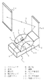
次に本発明について図面を参照して詳細に説明する。図1は、本発明の第1の実施形態を示す斜視図である。図2は、異物センサ回路の配置例を示す平面図である。プロジェクタ1の筐体2には、開口部3が設けられており、開口部レンズ4と投射ミラー5が対向するように配置されている。図示しない映像表示素子に生成した画像の表示光6は、開口部レンズ4を通して出射し投射ミラー5で反射され外部スクリーン11上に拡大投射される。図1には示していないが筐体2の内部には、プロジェクタを構成するために必要な、例えば液晶表示素子やDMDパネル素子などから成り画像を生成する映像表示素子、光源(ランプ)、画像表示光を開口部レンズまで導く光学系などが設けられている。なお、投射ミラー5を筐体2の開口部3を閉じることができる蓋部材(図1には示していない)に設置して、プロジェクタを使用しないときには蓋部材で開口部3を閉じるようにしてもよい。
Next, the present invention will be described in detail with reference to the drawings. FIG. 1 is a perspective view showing a first embodiment of the present invention. FIG. 2 is a plan view illustrating an arrangement example of the foreign matter sensor circuit. The
開口部レンズ4の映像表示素子側では、表示光6がほとんど広がらない(拡大されていない)状態であるため、開口部レンズ4から出射される表示光6の強度が非常に大きく表示光の通路の空気は熱せられて高温となる。さらに異物により表示光6を遮断された場合は、急激に温度が上昇して危険である。逆に表示光が出射される部分の温度を下げようとする場合は、表示光が広がった(表示素子よりも大きなサイズ)状態にすれば良いが、開口部および筐体が非常に大きくなり非現実的である。
Since the
本実施形態では、この開口部レンズ4と投射ミラー5の間の高温部に異物が入り込み危険な状態になるのを防止するために、高温となる検出したい範囲の表示光通路に異物センサ回路を設けている。すなわち筐体2の側壁7には、異物センサ回路を構成するセンサ発光部8、センサ受光部10および複数個のミラー9が設けられている。センサ発光部8からセンサ光は、表示光6の光路を横切るように放出されミラー9により複数回反射されセンサ受光部10で受光される。なお、図1には示していないが後述するように異物センサ回路は、異物によりセンサ光が遮断されたことを検出してランプを遮断したり、また異物の検出が解除されたことを検出して再度ランプ投射を再開し、映像の表示光を投射させたり、さらに異物検出の解除が安全と判断出来る時間を過ぎた場合は、電源を遮断するなどの動作を行うための電気回路を備えている。
In the present embodiment, in order to prevent a foreign matter from entering the high temperature portion between the
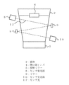
図2は、異物センサ回路の配置例(電気回路は示してない)を説明するための平面図である。図2のセンサ発光部8は、たとえば赤外線を放出する半導体レーザや発光ダイオードなどの半導体発光素子を用いセンサ光が広がらない構成にするか、もしくはある程度の指向性を持たせるようにする。センサ受光部10にはたとえばフォトトランジスタやフォトダイオードなどの半導体受光素子を用いる。ミラー9は対向するように設置されており、センサ発光部8から出射したセンサ光12は、ミラー9で反射させて確実にセンサ受光部10に入力するようにされている。ミラー9は、必要に応じて角度を可変できる調整機能を有する。またセンサ回路自体に角度調整機能を持たせてもよい。なお、図1および図2では2枚のミラーを対向するように配置した例を示したが、必要に応じてもっとミラーの数を増やしてもよい。
FIG. 2 is a plan view for explaining an arrangement example (electric circuit is not shown) of the foreign matter sensor circuit. The sensor light emitting unit 8 in FIG. 2 is configured so that the sensor light does not spread using a semiconductor light emitting element such as a semiconductor laser that emits infrared rays or a light emitting diode, or has a certain degree of directivity. For the sensor
センサ回路で使用するセンサ光の発光波長を、映像表示用途では使用しない波長(可視光でない)とし、かつセンサ回路用のミラー9をそれ専用にすれば映像を反射することなしにミラー9を配置できるので、コントラスト劣化を防止できる。
If the emission wavelength of the sensor light used in the sensor circuit is a wavelength that is not used in video display applications (not visible light) and the
図3は、本発明に用いる異物センサ回路のブロック図を示している。異物センサ回路は、センサ発光部、ミラー、センサ受光部および電気回路であるセンサ検出回路、ランプ制御回路、タイマー回路、電源制御回路から構成されている。センサ発光部8からのセンサ光をミラー9により効率よく反射させてセンサ受光部10によって正確に受光させる。センサ受光部10でうけた信号は、電気回路18を構成するセンサ検出回路13に送られH/Lレベルによりセンサ光の有り・無しを検出する。たとえば、正常であればH、センサ光が1箇所でも遮断されたらセンサ光無しのLとなり、異物侵入と検出する。
FIG. 3 shows a block diagram of the foreign matter sensor circuit used in the present invention. The foreign matter sensor circuit includes a sensor light emitting unit, a mirror, a sensor light receiving unit, and a sensor detection circuit which is an electric circuit, a lamp control circuit, a timer circuit, and a power supply control circuit. The sensor light from the sensor light emitting unit 8 is efficiently reflected by the
ランプ制御回路14は、センサ検出回路13によりセンサ光無しと検出された場合には、危険と判断しランプを遮断する。ランプ点灯制御素子を強制的に不点灯となるように制御する。例えばランプ点灯制御素子の電圧をトランジスタなどのスイッチにより切り替えることによりランプを遮断する。異物が無くなり検出解除時にはランプ制御回路14により再度ランプを点灯し投射を再開する。 When the sensor detection circuit 13 detects that there is no sensor light, the lamp control circuit 14 determines that it is dangerous and shuts off the lamp. The lamp lighting control element is controlled to be forcibly turned off. For example, the lamp is shut off by switching the voltage of the lamp lighting control element with a switch such as a transistor. When the foreign object disappears and the detection is canceled, the lamp control circuit 14 turns on the lamp again to resume projection.
また、ランプ不点灯ではなく、映像ミュートする機能も考えられる。映像ミュートによって全黒表示となり、開口部レンズ4から放射される光は無くなるので高温とならない。動作的には映像出力をミュートする。例として映像切替え部やOSD(オンスクリーン表示)の挿げ替え部、出力部またはIC(半導体)などの制御ミュートとなる。OSDの挿げ替え部前でのミュートではOSD表示が可能となる。
In addition, a function for muting the image instead of turning off the lamp is also conceivable. When the image is muted, all black is displayed, and the light emitted from the
さらにタイマー回路15は、センサ検出回路13によりセンサ光無しと検出したH/L電圧結果をソフト的に数秒に数回などの監視を行う。例えばCPU(半導体)内に内蔵されているカウンタ(タイマ回路機能)を使用し、センサ光無しの異物侵入結果の電圧が1秒に1回を10回確認し、10秒間すべて同じ電圧結果となれば危険と判断する。監視時間については任意となる。 Further, the timer circuit 15 monitors the H / L voltage result detected by the sensor detection circuit 13 as no sensor light, such as several times in a few seconds. For example, using the counter (timer circuit function) built in the CPU (semiconductor), the voltage of the result of foreign object intrusion without sensor light is confirmed 10 times per second, and the same voltage result can be obtained for 10 seconds. Judged as dangerous. The monitoring time is arbitrary.
電源制御回路16は、タイマー回路15の危険判断結果により電源を遮断する。例えば電源ON制御端子電圧をトランジスタなどのスイッチにより切り替える。また、IC(半導体)などによりソフト的に制御する。再度電源投入したときに異物検出の解除がされていない場合は、電源投入作業を中止する。異物検出時には、LEDもしくは表示パネルなどによりエラー表示(異物異常表示など)を行い警告する。また不点灯ではなく、映像ミュートする機能も考えられる時のエラー表示は、OSD(オンスクリーン表示)によって警告内容を表示する。異物による映像ミュートをOSDの挿げ替え前において元の映像信号だけをミュートする。これにより映像信号が全黒となり、OSDだけが表示できるようになり、スクリーン上にエラー表示が投射され確認できる。このエラー表示は、表示光が熱くならない程度(画面サイズの1/10以下)の小さなサイズで、熱くならない程度の明るさ(例えば白色は避けてグレー色など)にする。 The power supply control circuit 16 shuts off the power supply according to the danger judgment result of the timer circuit 15. For example, the power ON control terminal voltage is switched by a switch such as a transistor. In addition, it is controlled by an IC (semiconductor) or the like. If the foreign object detection is not canceled when the power is turned on again, the power-on operation is stopped. When a foreign object is detected, an error is displayed (such as a foreign object abnormality display) by an LED or a display panel to warn. In addition, an error display when the function of muting the image is conceivable instead of not lighting is displayed by OSD (on-screen display). Only the original video signal is muted before the OSD is replaced by a video mute caused by a foreign object. As a result, the video signal becomes all black and only the OSD can be displayed, and an error display is projected on the screen for confirmation. This error display has a small size that does not cause the display light to become hot (1/10 or less of the screen size) and brightness that does not become hot (for example, avoiding white and gray).
以上詳述したように本実施の形態では、異物の検出は1つのセンサ回路だけで行うことができるので、最小限の部品点数で実現でき、非常に効率的である。したがって部品点数や消費電流を軽減し、コストダウンできるという効果がある。また、高輝度のプロジェクタにおいても、異物による急激な温度上昇を未然に防げるセンサ回路を設けているので、プロジェクタを安全に使用できるという特徴がある。 As described above in detail, in the present embodiment, foreign matter can be detected by only one sensor circuit, so that it can be realized with a minimum number of parts and is very efficient. Therefore, the number of parts and current consumption can be reduced and the cost can be reduced. In addition, a projector with high brightness has a feature that a projector can be used safely because a sensor circuit is provided to prevent a sudden temperature rise due to foreign matter.
図4は、本発明の第2の実施形態を示す平面図であり、異物センサ回路の部分のみを表してある。センサ発光部からのセンサ光を反射させるミラーの数は、検出の範囲と異物の大きさなどにより異なるため、反射回数が増える場合は、ミラーの枚数を増やすだけでなく、図4に示すように大型ミラーを対向するように配置して1枚のミラー内で数箇所を反射のポイントにすることも可能である。本実施形態では、ミラーのサイズおよび反射回数を変更するだけで、検出範囲が任意に設定できる。また検出したい異物のサイズも同様に任意に設定できる。
FIG. 4 is a plan view showing a second embodiment of the present invention, and shows only the foreign matter sensor circuit portion. Since the number of mirrors that reflect the sensor light from the sensor light emitting unit varies depending on the detection range and the size of the foreign matter, when the number of reflections increases, not only the number of mirrors is increased, but also as shown in FIG. It is also possible to arrange large mirrors so as to face each other and make several reflection points within one mirror. In the present embodiment, the detection range can be arbitrarily set simply by changing the size of the mirror and the number of reflections. Similarly, the size of a foreign object to be detected can be arbitrarily set.
1 プロジェクタ
2 筐体
3 開口部
4 開口部レンズ
5 投射ミラー
6 表示光
7 側壁
8 センサ発光部
9 ミラー
10 センサ受光部
11 外部スクリーン
12 センサ光
13 センサ検出回路
14 ランプ制御回路
15 タイマー回路
16 電源制御回路
18 電気回路
DESCRIPTION OF
Claims (14)
開口部を有する筐体と、 A housing having an opening;
センサ光を出射する発光部、当該センサ光を受光する受光部、及び当該受光部からの信号に基づいてプロジェクタを制御する制御部を含む異物検出器と、を有し、 A foreign matter detector including a light emitting unit that emits sensor light, a light receiving unit that receives the sensor light, and a control unit that controls the projector based on a signal from the light receiving unit;
前記映像表示素子に生成された画像の表示光は前記開口部を通り、 The display light of the image generated in the video display element passes through the opening,
前記センサ光は前記開口部を通る前記表示光の光路を横切ることを特徴とするプロジェクタ。 The projector according to claim 1, wherein the sensor light crosses an optical path of the display light passing through the opening.
当該センサ光を反射するミラーを有することを特徴とするプロジェクタ。 A projector comprising a mirror that reflects the sensor light.
前記センサ光を反射する複数のミラーを有し、 A plurality of mirrors for reflecting the sensor light;
前記複数のミラーは、前記開口部を通る前記表示光を挟むように対向させて配置されていることを特徴とするプロジェクタ。 The projector, wherein the plurality of mirrors are arranged to face each other so as to sandwich the display light passing through the opening.
前記複数のミラーのうち少なくとも一のミラーは、前記センサ光を2回以上反射することを特徴とするプロジェクタ。 At least one of the plurality of mirrors reflects the sensor light twice or more.
前記センサ光を反射する2つのミラーを有し、 Two mirrors reflecting the sensor light;
前記2つのミラーは、前記開口部を通る前記表示光を挟むように対向させて配置されており、 The two mirrors are arranged to face each other so as to sandwich the display light passing through the opening,
前記センサ光は前記2つのミラーの間で多重反射することを特徴とするプロジェクタ。 The projector is characterized in that the sensor light is multiple-reflected between the two mirrors.
前記筐体の外側に投射ミラーを有し、 A projection mirror outside the housing;
前記開口部を通った前記表示光が前記投射ミラーで反射されることを特徴とするプロジェクタ。 The projector, wherein the display light that has passed through the opening is reflected by the projection mirror.
前記投射ミラーは、倒れ込み及び引き起こし可能にプロジェクタに取り付けられており、引き起こし状態では投射光学系を構成し、倒れ込み状態では前記開口部を閉塞することを特徴とするプロジェクタ。 The projection mirror is attached to the projector so as to be able to fall down and cause it, and constitutes a projection optical system in the raised state, and closes the opening in the lowered state.
前記センサ光は、半導体発光素子により放出された赤外線であることを特徴とするプロジェクタ。 The projector according to claim 1, wherein the sensor light is an infrared ray emitted by a semiconductor light emitting element.
前記制御部は、前記センサ受光部からの前記信号が所定の時間前記センサ光の不検出を示した場合にランプを消灯することを特徴とするプロジェクタ。 The control unit turns off the lamp when the signal from the sensor light receiving unit indicates that the sensor light is not detected for a predetermined time.
前記制御部は、前記センサ受光部からの前記信号が前記センサ光の検出を示した場合にランプを点灯することを特徴とするプロジェクタ。 The control unit turns on a lamp when the signal from the sensor light receiving unit indicates detection of the sensor light.
前記制御部は、前記センサ受光部からの前記信号が所定の時間前記センサ光の不検出を示した場合に映像をミュートすることを特徴とするプロジェクタ。 The projector, wherein the control unit mutes an image when the signal from the sensor light receiving unit indicates that the sensor light is not detected for a predetermined time.
前記制御部は、前記センサ受光部からの前記信号が所定の時間前記センサ光の不検出を示した場合に映像をミュートし、かつ、オンスクリーン表示を行うことを特徴とするプロジェクタ。 The control unit is configured to mute the video and perform on-screen display when the signal from the sensor light receiving unit indicates that the sensor light is not detected for a predetermined time.
前記制御部は、前記オンスクリーン表示の少なくとも一部が灰色であることを特徴とするプロジェクタ。 The projector is characterized in that at least a part of the on-screen display is gray.
Priority Applications (1)
| Application Number | Priority Date | Filing Date | Title |
|---|---|---|---|
| JP2006233691A JP4019099B2 (en) | 2006-08-30 | 2006-08-30 | Projector with foreign object sensor circuit |
Applications Claiming Priority (1)
| Application Number | Priority Date | Filing Date | Title |
|---|---|---|---|
| JP2006233691A JP4019099B2 (en) | 2006-08-30 | 2006-08-30 | Projector with foreign object sensor circuit |
Related Parent Applications (1)
| Application Number | Title | Priority Date | Filing Date |
|---|---|---|---|
| JP2006020730A Division JP3886521B2 (en) | 2006-01-30 | 2006-01-30 | Projector with foreign object sensor circuit |
Publications (2)
| Publication Number | Publication Date |
|---|---|
| JP2007034318A JP2007034318A (en) | 2007-02-08 |
| JP4019099B2 true JP4019099B2 (en) | 2007-12-05 |
Family
ID=37793563
Family Applications (1)
| Application Number | Title | Priority Date | Filing Date |
|---|---|---|---|
| JP2006233691A Expired - Fee Related JP4019099B2 (en) | 2006-08-30 | 2006-08-30 | Projector with foreign object sensor circuit |
Country Status (1)
| Country | Link |
|---|---|
| JP (1) | JP4019099B2 (en) |
Families Citing this family (7)
| Publication number | Priority date | Publication date | Assignee | Title |
|---|---|---|---|---|
| JP2012252252A (en) | 2011-06-06 | 2012-12-20 | Seiko Epson Corp | Projector |
| JP2013105171A (en) * | 2011-11-17 | 2013-05-30 | Seiko Epson Corp | Projector and control method of the same |
| JP5915113B2 (en) * | 2011-11-22 | 2016-05-11 | 株式会社リコー | Projector device |
| JP2014149492A (en) | 2013-02-04 | 2014-08-21 | Ricoh Co Ltd | Image projection device |
| JP6167595B2 (en) * | 2013-03-26 | 2017-07-26 | セイコーエプソン株式会社 | projector |
| JP2015059954A (en) * | 2013-09-17 | 2015-03-30 | カシオ計算機株式会社 | Projector, air filter exchange control program and air filter exchange detection method |
| JP6070871B2 (en) * | 2016-01-27 | 2017-02-01 | セイコーエプソン株式会社 | Projector and control method thereof |
-
2006
- 2006-08-30 JP JP2006233691A patent/JP4019099B2/en not_active Expired - Fee Related
Also Published As
| Publication number | Publication date |
|---|---|
| JP2007034318A (en) | 2007-02-08 |
Similar Documents
| Publication | Publication Date | Title |
|---|---|---|
| US7093943B2 (en) | Projector with foreign matter detecting means | |
| JP4019099B2 (en) | Projector with foreign object sensor circuit | |
| US20130128240A1 (en) | Projector and method of controlling the same | |
| JP3886521B2 (en) | Projector with foreign object sensor circuit | |
| JP4293233B2 (en) | projector | |
| JP4887947B2 (en) | Projection type image display device | |
| JP2008180921A (en) | Projection type display apparatus | |
| JP2001075170A (en) | Projection device and its safety device | |
| JP2010243921A (en) | Projection video display apparatus | |
| JP2006330447A (en) | Front projector | |
| US9618833B2 (en) | Image projection apparatus | |
| JP2006119676A5 (en) | ||
| JP2007219225A (en) | Projector | |
| JP4765287B2 (en) | projector | |
| JP5915113B2 (en) | Projector device | |
| JP5245619B2 (en) | Projection display | |
| JP2009020763A (en) | Extinction type sensor | |
| WO2021002048A1 (en) | Projection video display device and obstacle detection method | |
| JP6070871B2 (en) | Projector and control method thereof | |
| JP2002196301A (en) | Projection type picture display device and projection type picture display element | |
| JP2015001553A (en) | Projector device | |
| KR100396679B1 (en) | LCD Projector and of the same screen change method | |
| JP2007171872A (en) | Image display projector | |
| US11549893B2 (en) | Projector | |
| JP4940591B2 (en) | Image display device and laser device |
Legal Events
| Date | Code | Title | Description |
|---|---|---|---|
| RD01 | Notification of change of attorney |
Free format text: JAPANESE INTERMEDIATE CODE: A7421 Effective date: 20070126 |
|
| TRDD | Decision of grant or rejection written | ||
| A01 | Written decision to grant a patent or to grant a registration (utility model) |
Free format text: JAPANESE INTERMEDIATE CODE: A01 Effective date: 20070904 |
|
| A61 | First payment of annual fees (during grant procedure) |
Free format text: JAPANESE INTERMEDIATE CODE: A61 Effective date: 20070921 |
|
| R150 | Certificate of patent or registration of utility model |
Free format text: JAPANESE INTERMEDIATE CODE: R150 |
|
| FPAY | Renewal fee payment (event date is renewal date of database) |
Free format text: PAYMENT UNTIL: 20100928 Year of fee payment: 3 |
|
| FPAY | Renewal fee payment (event date is renewal date of database) |
Free format text: PAYMENT UNTIL: 20100928 Year of fee payment: 3 |
|
| FPAY | Renewal fee payment (event date is renewal date of database) |
Free format text: PAYMENT UNTIL: 20110928 Year of fee payment: 4 |
|
| FPAY | Renewal fee payment (event date is renewal date of database) |
Free format text: PAYMENT UNTIL: 20120928 Year of fee payment: 5 |
|
| FPAY | Renewal fee payment (event date is renewal date of database) |
Free format text: PAYMENT UNTIL: 20120928 Year of fee payment: 5 |
|
| S531 | Written request for registration of change of domicile |
Free format text: JAPANESE INTERMEDIATE CODE: R313531 |
|
| FPAY | Renewal fee payment (event date is renewal date of database) |
Free format text: PAYMENT UNTIL: 20120928 Year of fee payment: 5 |
|
| R350 | Written notification of registration of transfer |
Free format text: JAPANESE INTERMEDIATE CODE: R350 |
|
| FPAY | Renewal fee payment (event date is renewal date of database) |
Free format text: PAYMENT UNTIL: 20130928 Year of fee payment: 6 |
|
| LAPS | Cancellation because of no payment of annual fees |