JP4980056B2 - Gas flow direction changing apparatus and gas flow direction changing method for airbag system - Google Patents
Gas flow direction changing apparatus and gas flow direction changing method for airbag system Download PDFInfo
- Publication number
- JP4980056B2 JP4980056B2 JP2006525414A JP2006525414A JP4980056B2 JP 4980056 B2 JP4980056 B2 JP 4980056B2 JP 2006525414 A JP2006525414 A JP 2006525414A JP 2006525414 A JP2006525414 A JP 2006525414A JP 4980056 B2 JP4980056 B2 JP 4980056B2
- Authority
- JP
- Japan
- Prior art keywords
- cushion
- hood
- discharge
- inflation gas
- outer edge
- Prior art date
- Legal status (The legal status is an assumption and is not a legal conclusion. Google has not performed a legal analysis and makes no representation as to the accuracy of the status listed.)
- Expired - Fee Related
Links
Images


Classifications
-
- B—PERFORMING OPERATIONS; TRANSPORTING
- B60—VEHICLES IN GENERAL
- B60R—VEHICLES, VEHICLE FITTINGS, OR VEHICLE PARTS, NOT OTHERWISE PROVIDED FOR
- B60R21/00—Arrangements or fittings on vehicles for protecting or preventing injuries to occupants or pedestrians in case of accidents or other traffic risks
- B60R21/02—Occupant safety arrangements or fittings, e.g. crash pads
- B60R21/16—Inflatable occupant restraints or confinements designed to inflate upon impact or impending impact, e.g. air bags
- B60R21/23—Inflatable members
- B60R21/231—Inflatable members characterised by their shape, construction or spatial configuration
- B60R21/233—Inflatable members characterised by their shape, construction or spatial configuration comprising a plurality of individual compartments; comprising two or more bag-like members, one within the other
-
- B—PERFORMING OPERATIONS; TRANSPORTING
- B60—VEHICLES IN GENERAL
- B60R—VEHICLES, VEHICLE FITTINGS, OR VEHICLE PARTS, NOT OTHERWISE PROVIDED FOR
- B60R21/00—Arrangements or fittings on vehicles for protecting or preventing injuries to occupants or pedestrians in case of accidents or other traffic risks
- B60R21/02—Occupant safety arrangements or fittings, e.g. crash pads
- B60R21/16—Inflatable occupant restraints or confinements designed to inflate upon impact or impending impact, e.g. air bags
- B60R21/23—Inflatable members
- B60R21/231—Inflatable members characterised by their shape, construction or spatial configuration
- B60R21/2334—Expansion control features
- B60R21/2346—Soft diffusers
Landscapes
- Engineering & Computer Science (AREA)
- Mechanical Engineering (AREA)
- Air Bags (AREA)
Description
本発明は、乗り物の乗員を怪我から保護するためのシステムおよび方法に関する。特に、本発明は、エアバッグクッションの膨張したときの外形特性を向上させる方向変更フードに関する。 The present invention relates to a system and method for protecting a vehicle occupant from injury. In particular, the present invention relates to a direction change hood that improves the external characteristics when an airbag cushion is inflated.
現在、膨張可能な安全拘束装置、すなわち、エアバッグを搭載することが多くの新車に対して法的に要求されている。エアバッグは、典型的には、ハンドル内や車の補助席側のダッシュボード内に搭載される。さらに、エアバッグは、側方衝撃に対する保護を提供するために乗員の傍で膨張するように搭載されたり、衝撃から膝を保護するために膝の正面で膨張するように搭載されたり、その他、計画的な箇所で膨張するように搭載される。 Currently, it is legally required for many new vehicles to be equipped with an inflatable safety restraint device, ie, an airbag. The airbag is typically mounted in a steering wheel or a dashboard on the side of an auxiliary seat of a car. In addition, the airbag is mounted to inflate beside the occupant to provide protection against side impacts, or to be inflated in front of the knees to protect the knee from impact, Mounted to expand at planned locations.
事故が起こったときには、車の中のセンサシステムが衝撃の状況を検出し、インフレータの点火を起動する。すると、インフレータからの膨張ガスがエアバッグクッションを満たし、即座に膨張させ、車内の面に対する衝撃から運転手や乗員を保護する。車の通常の走行中は、エアバッグは、典型的には、該エアバッグを干渉から保護し且つ車の内部外観を魅力的なものとするためにカバーの後ろに収容されている。 When an accident occurs, a sensor system in the car detects the impact situation and activates the inflator ignition. Then, the inflation gas from the inflator fills the airbag cushion and immediately inflates to protect the driver and the occupant from impacts on the interior surface. During normal driving of the car, the airbag is typically housed behind the cover to protect the airbag from interference and to make the interior appearance of the car attractive.
また、エアバッグは、特定の予測される状態にある車の乗員を保護するように設計されることが多い。しかしながら、乗り物の多くの乗員は、衝突が起こったときには適正位置から外れてしまう(OOP(out-of-position))。したがって、典型的な衝撃位置から外れた乗員を保護するようにエアバッグが設計されると有利である。補助席側の正面衝突用のエアバッグの場合、乗員を保護するためには、幾分か大きなクッションが利用される。そして、クッションは、天井近くから乗員の膝まで延在し、様々な乗員の位置において衝撃に対する保護を提供するように相当な大きさの横方向の寸法を有している。 Also, airbags are often designed to protect a vehicle occupant in a particular predicted state. However, many occupants of a vehicle are out of position (OOP (out-of-position)) when a collision occurs. Therefore, it is advantageous if the airbag is designed to protect occupants out of the typical impact position. In the case of an airbag for a frontal collision on the side of the auxiliary seat, a somewhat larger cushion is used to protect the occupant. The cushion then extends from near the ceiling to the occupant's knees and has significant lateral dimensions to provide protection against impacts at various occupant positions.
また、補助席側の正面衝突用のエアバッグは、車のインストルメントパネル内に搭載されることが多い。また、こうしたエアバッグは、インストルメントパネルの上面に搭載されることが多い。また、インストルメントパネル内には、インフレータが搭載されており、このインフレータは、膨張ガスが上方に流れてクッションを上方に拡大させるように配置される。その結果、クッションは、乗員の頭部の予測される位置に向って膨張する傾向にある。そして、その後、乗員の胴に対する衝撃を和らげるようにクッションの残りの部分が膨張ガスで満たされる。しかしながら、クッションへの頭部のみの初期の接触は、首に過剰な負荷をかけてしまう傾向にあることから、こうした膨張は、望ましくない。さらに、こうした膨張は、適正位置から外れた乗員に対して少ない保護しか提供しない。 Further, the airbag for frontal collision on the auxiliary seat side is often mounted in the instrument panel of the car. Moreover, such an airbag is often mounted on the upper surface of the instrument panel. Further, an inflator is mounted in the instrument panel, and this inflator is arranged so that the inflation gas flows upward and expands the cushion upward. As a result, the cushion tends to expand toward the expected position of the occupant's head. Thereafter, the remaining portion of the cushion is filled with the inflation gas so as to reduce the impact on the occupant's torso. However, such an expansion is undesirable because initial head-only contact with the cushion tends to overload the neck. In addition, such inflation provides less protection for occupants who are out of position.
こうした問題点に対する公知の解決策は、クッション紐や特別なクッション折畳技術やループ型のディフューザのような内部装置を利用することである。しかしながら、典型的には、こうした解決策には、制限がある。例えば、紐は、乗員に向うクッションの深さを制限してしまい、このため、中間のシートの位置またはリアシートの位置に対する素早い拘束を減少させてしまう傾向にある。また、特別なクッション折畳技術は、実行するのが困難であるし、実行するコストが高いことが多い。また、ループ型のディフューザは、概して、展開性能に関して限定的な改善しか提供せず、典型的には、集中的なガスの方向転換を行うことができない。 A known solution to these problems is to use internal devices such as cushion strings, special cushion folding techniques, and loop diffusers. However, typically these solutions have limitations. For example, the string limits the depth of the cushion toward the occupant and thus tends to reduce quick restraints on the position of the intermediate seat or the position of the rear seat. Also, special cushion folding techniques are difficult to perform and are often expensive to perform. Also, loop diffusers generally provide only limited improvements in deployment performance and typically cannot perform intensive gas redirection.
本発明の装置および方法は、当該技術分野、特に、現在利用可能なエアバッグモジュールによっては十分に解決されていない当該技術分野における問題やニーズに対応して開発されたものである。したがって、本発明の全体的な目的は、従来技術における欠点を改善するエアバッグモジュールとそれに関連する方法を提供することにある。 The apparatus and method of the present invention have been developed in response to problems and needs in the art, particularly in the art that are not fully resolved by currently available airbag modules. Accordingly, it is an overall object of the present invention to provide an airbag module and associated method that remedies the shortcomings of the prior art.
上記目的を達成するために、ここで1つの実施形態として実施されて広義に説明する発明によれば、エアバッグモジュールは、クッションと、インフレータと、クッション内に配置された方向変更フードとを有する。インフレータは、クッションと方向変更フードとを収容しているハウジング内に配置される。また、インフレータは、電子制御装置(ECU)に接続されており、ECUは、衝突センサ、例えば、加速度計に連結され、該ECUが衝突センサによる衝突の検出に応答してインフレータに始動信号を送信することができるようになっている。また、乗り物は、フロントガラスやインストルメントパネルを有し、これらフロントガラスやインストルメントパネルからクッションが展開する。 In order to achieve the above object, according to the invention which is implemented as one embodiment and described in a broad sense, the airbag module includes a cushion, an inflator, and a direction change hood disposed in the cushion. . The inflator is disposed in a housing that houses the cushion and the direction changing hood. The inflator is connected to an electronic control unit (ECU). The ECU is connected to a collision sensor, for example, an accelerometer, and the ECU transmits a start signal to the inflator in response to detection of a collision by the collision sensor. Can be done. Further, the vehicle has a windshield and an instrument panel, and a cushion is developed from the windshield and the instrument panel.
また、クッションは、第1部分と第2部分とを有し、膨張状態では、第1部分は、乗員の頭部の予測される位置に向かって第2部分の上方に配置されている。方向変更フードがなければ、膨張ガスは、第1部分内に流入する傾向にある。方向変更フードは、インストルメントパネル内のインフレータとハウジングとに隣接した入口部分を有する。また、方向変更フードは、前方を向いた領域と後方を向いた領域とを備えた出口部分と、該出口部分の概して上方の頂部部分とを有する。 The cushion has a first portion and a second portion. In the inflated state, the first portion is disposed above the second portion toward the predicted position of the head of the occupant. Without the direction change hood, the inflation gas tends to flow into the first portion. The redirecting hood has an inlet portion adjacent to the inflator and housing in the instrument panel. The redirecting hood also has an exit portion with a forward facing region and a rear facing region, and a top portion generally above the exit portion.
また、出口部分の後方を向いた領域には、放出開口が形成されており、出口部分の前方を向いた領域には、補助放出開口が形成されている。方向変更フードの頂部部分は、インフレータからの膨張ガスの殆どを受け入れ、該膨張ガスを下方へと方向を変更させ、放出開口を介して方向変更フードから流出させる。また、膨張ガスは、放出方向に沿って放出開口から流出する。放出方向は、それが概ねクッションの第2部分に向うように少なくとも60度の角度だけ水平面から下方に向いている。 Further, a discharge opening is formed in a region facing the rear of the outlet portion, and an auxiliary discharge opening is formed in a region facing the front of the outlet portion. The top portion of the redirecting hood receives most of the inflation gas from the inflator, redirects the inflation gas downward and out of the redirecting hood through the discharge opening. The inflation gas flows out from the discharge opening along the discharge direction. The discharge direction is directed downward from the horizontal plane by an angle of at least 60 degrees so that it is generally toward the second part of the cushion.
また、頂部部分は、補助放出開口に向って膨張ガスの一部を下方へと方向を変更させる。この膨張ガスの一部は、補助放出方向に沿って補助放出開口から流出し、クッションの前方を向いた領域への幾つかの通気を提供する。また、方向変更フードは、クッションへのさらなる横方向の通気を提供するために両側に通気孔を有する。 Further, the top portion changes the direction of a part of the expansion gas downward toward the auxiliary discharge opening. A portion of this inflation gas flows out of the auxiliary discharge opening along the auxiliary discharge direction and provides some ventilation to the area facing the front of the cushion. The redirection hood also has vents on both sides to provide additional lateral ventilation to the cushion.
また、クッションは、第1側部と、第2側部と、取付部分とを有し、該取付部分において、クッションがハウジングに取り付けられる。したがって、取付部分は、クッションが膨張したときには、インストルメントパネルに隣接して配置されることになる。また、方向変更フードは、第1布部分と第2布部分とを有し、これら布は、互いに一体的に形成されており、横方向に沿って互いに略対称となっている。また、第1布部分は、第1側部分を有し、第2布部分は、第2側部分を有し、これら側部分は、クッションの第1側部と第2側部とに略平行な位置に膨張する。 The cushion has a first side portion, a second side portion, and an attachment portion, and the cushion is attached to the housing at the attachment portion. Accordingly, the attachment portion is disposed adjacent to the instrument panel when the cushion is inflated. The direction change hood has a first cloth part and a second cloth part, and these cloths are formed integrally with each other and are substantially symmetrical with each other along the lateral direction. The first fabric portion has a first side portion, the second fabric portion has a second side portion, and these side portions are substantially parallel to the first side portion and the second side portion of the cushion. It expands to a proper position.
また、第1布部分は、第1外側エッジを有し、第2布部分は、第2外側エッジを有し、これら外側エッジに沿って第1布部分と第2布部分とが縫合せのような方法によって互いに取り付けられる。また、第1布部分は、第1放出エッジと第1補助放出エッジとを有し、第2布部分は、第2放出エッジと第2補助放出エッジとを有する。これら第1放出エッジと第2放出エッジと第1補助放出エッジと第2補助放出エッジとは、第1外側エッジおよび第2外側エッジに隣接しており、放出開口および補助放出開口を提供するために取り付けられていないままとなっている。 The first fabric portion has a first outer edge, the second fabric portion has a second outer edge, and the first and second fabric portions are sewn along the outer edge. They are attached to each other by such a method. The first fabric portion has a first discharge edge and a first auxiliary discharge edge, and the second fabric portion has a second discharge edge and a second auxiliary discharge edge. The first emission edge, the second emission edge, the first auxiliary emission edge, and the second auxiliary emission edge are adjacent to the first outer edge and the second outer edge and provide an emission opening and an auxiliary emission opening. It remains unattached.
作動時、ECUは、衝突の検出に応答してインフレータに始動信号を送信する。すると、インフレータは、膨張ガスを排出し、この膨張ガスは、入口部分を通って方向変更フードに流入し、頂部部分内へと流れる。頂部部分は、膨張ガスを出口部分内へと方向転換させ、出口部分は、放出開口および補助放出開口を介して膨張ガスを排出する。放出開口を介して流出した膨張ガスは、クッションの第2部分に向って移動し、第2部分の膨張を促進させ、これにより、乗員、特に、適正位置から外れた乗員に高い衝撃緩和を提供する。 In operation, the ECU transmits a start signal to the inflator in response to detection of a collision. The inflator then discharges the inflation gas, which flows through the inlet portion into the redirecting hood and flows into the top portion. The top portion redirects the inflation gas into the exit portion, which exits the inflation gas through the discharge opening and the auxiliary discharge opening. The inflation gas that flows out through the discharge opening moves toward the second part of the cushion and promotes the expansion of the second part, thereby providing high impact mitigation for the occupant, particularly occupants who are out of position. To do.
また、組立前、エアバッグモジュールは、方向変更フードとなるフードパネルと、クッションとなるクッションパネルとを有する。また、エアバッグ組立体は、保持リングと、該保持リングに係合可能な複数のナットとを有する。フードパネルは、第1部分と第2部分とを有するが、これら部分の外側エッジは、方向変更フードを形成するために互いに取り付けられてはいない。 In addition, before assembly, the airbag module includes a hood panel serving as a direction change hood and a cushion panel serving as a cushion. The airbag assembly includes a retaining ring and a plurality of nuts that can be engaged with the retaining ring. The hood panel has a first portion and a second portion, but the outer edges of these portions are not attached to each other to form a redirecting hood.
フードパネルは、第1布部分と第2布部分とを互いに接続する中央細長片を有し、この中央細長片は、第1布部分と第2布部分とに一体的に形成されている。また、膨張ガスをインフレータから方向変更フードに流入させるために中央細長片に入口開口が形成されている。また、中央細長片は、入口開口を包囲する周辺部分を有する。周辺部分には、方向変更フードをクッションに取り付けやすいように、複数の取付穴と複数の整列穴とが形成されている。また、クッションは、同様の構成の取付穴および整列穴を有する周辺部分を備えた入口開口を有する。 The hood panel has a central elongated piece that connects the first fabric portion and the second fabric portion to each other, and the central elongated piece is formed integrally with the first fabric portion and the second fabric portion. Also, an inlet opening is formed in the central strip to allow inflation gas to flow from the inflator into the direction change hood. The central strip also has a peripheral portion surrounding the inlet opening. A plurality of attachment holes and a plurality of alignment holes are formed in the peripheral portion so that the direction change hood can be easily attached to the cushion. The cushion also has an inlet opening with a peripheral portion having similarly configured mounting and alignment holes.
また、保持リングは、管状壁と、該管状壁の一端から外方へ延在するフランジとを有する。フランジにはファスナが一体的に形成され或いは取り付けられ、これらファスナは、クッションおよび方向変更フードの取付穴に整列するようにエアバッグモジュールのその他の構成要素に向って延びている。ファスナは、ボルトやその他のネジ部材などである。さらに、フランジには、タブが形成されており、これらタブは、整列穴に整列するようにエアバッグモジュールのその他の構成要素に向って延びている。 The retaining ring also has a tubular wall and a flange extending outward from one end of the tubular wall. Fasteners are integrally formed or attached to the flanges and extend toward the other components of the airbag module to align with the mounting holes of the cushion and the redirecting hood. The fastener is a bolt or other screw member. In addition, tabs are formed on the flanges that extend toward the other components of the airbag module to align with the alignment holes.
また、ハウジングは、側壁と取付プレートとを有し、取付プレートには、フードパネルおよびクッションパネルのものと同様な構成の入口開口が形成されている。また、取付プレートは、入口開口を包囲する周辺部分を有し、この周辺部分には、取付穴および整列穴が形成されている。インフレータは、該インフレータが作動したときに複数の穴を介して膨張ガスを通気する排気部分と、ECUに連結される接続部分とを有する。排気部分と接続部分とは、略円筒形の形をしている。また、排気部分と接続部分との間から外方へフランジが延びている。このフランジは、方向変更フードおよびクッションおよびハウジングの取付穴ならびに保持リングのファスナに整列する取付穴を有する。 The housing has a side wall and a mounting plate, and the mounting plate is formed with an inlet opening having a configuration similar to that of the hood panel and the cushion panel. The mounting plate has a peripheral portion surrounding the inlet opening, and a mounting hole and an alignment hole are formed in the peripheral portion. The inflator has an exhaust part that ventilates inflation gas through a plurality of holes when the inflator is activated, and a connection part that is connected to the ECU. The exhaust part and the connection part have a substantially cylindrical shape. A flange extends outward from between the exhaust portion and the connection portion. The flange has mounting holes aligned with the mounting holes of the redirecting hood and cushion and housing and the fasteners of the retaining ring.
また、エアバッグモジュールは、最初に、クッションパネルおよびフードパネルの入口開口周りでクッションパネルとフードパネルとを互いに取り付けることによって組み立てられる。そして、クッションパネルが閉じられてクッションが形成されると共にフードパネルが閉じられて方向変更フードが形成される。1つの方法の例によれば、クッションパネルのエッジが互いに取り付けられてクッションが形成される。そして、フードパネルの第1部分と第2部分とが保持リングおよびフードパネルおよびクッションパネルの入口開口を介してクッションから引っ張り出される。そして、第1部分および第2部分の外側エッジ同士が取り付けられ、第1部分と第2部分とが入口開口に挿入されてクッション内に戻されることで方向変更フードが形成される。 The airbag module is also assembled by first attaching the cushion panel and the hood panel together around the entrance opening of the cushion panel and the hood panel. The cushion panel is closed to form a cushion, and the hood panel is closed to form a direction changing hood. According to one method example, the edges of the cushion panels are attached together to form a cushion. Then, the first portion and the second portion of the hood panel are pulled out of the cushion through the retaining ring, the hood panel, and the entrance opening of the cushion panel. Then, the outer edges of the first part and the second part are attached to each other, and the direction change hood is formed by inserting the first part and the second part into the entrance opening and returning them into the cushion.
そして、保持リングがクッションおよび方向変更フードの入口開口に挿入される。そして、クッションおよび方向変更フードおよびハウジングおよびインフレータの取付穴にファスナが挿入される。保持リングと方向変更フードとクッションとハウジングとインフレータとが集まると、タブが方向変更フードおよびクッションおよびハウジングの整列穴に入り込む。そして、インフレータの排気部分がハウジングおよびクッションおよび方向変更フードおよび保持リングの入口開口を通る。そして、ファスナの端部にナットが螺合されて締結されることで保持リングと方向変更フードとクッションとハウジングとインフレータとが互いに取り付けられる。 A retaining ring is then inserted into the cushion and the inlet opening of the direction change hood. Then, fasteners are inserted into the mounting holes of the cushion, the direction changing hood, the housing, and the inflator. When the retaining ring, the redirecting hood, the cushion, the housing, and the inflator are assembled, the tab enters the alignment hole of the redirecting hood, the cushion, and the housing. The exhaust portion of the inflator then passes through the housing, the cushion, the direction change hood and the inlet opening of the retaining ring. Then, the retaining ring, the direction changing hood, the cushion, the housing, and the inflator are attached to each other by screwing and fastening the nut to the end portion of the fastener.
そして、クッションと方向変更フードとを収容空間内に単にコンパクト化することによってクッションと方向変更フードとが折り畳まれる。特殊な折畳方法や順序立てられた折畳方法を利用する必要はなく、単に、クッションと方向変更クッションとを収容空間内に押し込めばよい。そして、クッションの膨張特性を決定するに当たってクッションおよび方向変更フードの折畳の形態が比較的小さな役割しか果たさないように、方向変更フードは、クッションに流入する膨張ガスを方向付ける。 Then, the cushion and the direction changing hood are folded by simply making the cushion and the direction changing hood compact in the accommodation space. There is no need to use a special folding method or an ordered folding method, and the cushion and the direction changing cushion may be simply pushed into the accommodation space. The direction change hood directs the inflation gas flowing into the cushion so that the cushion and direction change hood fold form play a relatively small role in determining the expansion characteristics of the cushion.
本発明の別の1つの実施形態では、方向変更フードから膨張ガスが流出する前に方向変更フードが膨張可能なように、放出エッジ同士および補助放出エッジ同士が取り付けられている。方向変更フレーム内の膨張ガスが方向変更フードの外側のガスに対して予め定められた圧力差に達したとき、破断継ぎ目が破れることで放出開口および補助放出開口が開かれる。その結果、方向変更フードから大部分の膨張ガスが放出される前に、放出開口と補助放出開口とが適切に配置されることになる。 In another embodiment of the present invention, the discharge edges and the auxiliary discharge edges are attached so that the direction change hood can expand before the inflation gas flows out of the direction change hood. When the inflation gas in the direction change frame reaches a predetermined pressure differential with respect to the gas outside the direction change hood, the break seam is broken to open the discharge opening and the auxiliary discharge opening. As a result, the discharge opening and the auxiliary discharge opening are properly arranged before most of the inflation gas is released from the direction changing hood.
また、本発明の別の1つの実施形態では、破断不能な継ぎ目を形成する縫合せのような壊れやすくない方法によって放出エッジ同士および補助放出エッジ同士が取り付けられる。例えば、外側エッジおよび放出エッジおよび補助放出エッジが連続的で均一な縫合せプロセスによって縫い合わされる。破断可能な継ぎ目の代わりに、放出エッジおよび補助放出エッジに隣接した出口部分のところに複数の孔が形成される。予め定められた圧力差に達したとき、出口部分が孔に沿って裂けることで放出開口および補助放出開口が開かれ、これにより、膨張ガスが排出される。 In another embodiment of the invention, the discharge edges and auxiliary discharge edges are attached by a non-breakable method such as stitching to form an unbreakable seam. For example, the outer and discharge edges and auxiliary discharge edges are stitched together by a continuous and uniform stitching process. Instead of a breakable seam, a plurality of holes are formed at the exit portion adjacent to the discharge edge and the auxiliary discharge edge. When a predetermined pressure difference is reached, the outlet portion tears along the hole to open the discharge opening and the auxiliary discharge opening, thereby expelling the inflation gas.
また、本発明の別の1つの実施形態では、クッション内に非対称な放出を提供するように方向変更フードが向けられている。例えば、方向変更フードがクッション内で傾くような角度だけ方向変更フードの入口開口周りで取付穴と整列穴とが回転せしめられている。放出開口が中心から外れた位置にあることから、非対称な横方向の膨張を提供する角度に沿って膨張ガスが放出されることになる。 In another embodiment of the invention, the redirecting hood is oriented to provide an asymmetric release within the cushion. For example, the mounting hole and the alignment hole are rotated around the inlet opening of the direction change hood by an angle such that the direction change hood is inclined in the cushion. Because the discharge opening is off-center, the inflation gas will be released along an angle that provides asymmetric lateral expansion.
本発明のエアバッグモジュールおよびそれに関連する方法を利用することによって、乗員に対する衝撃を効果的に和らげるようにエアバッグが膨張する。さらに、エアバッグモジュールは、効率的で且つコスト効率良く製造可能である。本発明のこうした特徴や利点およびその他の特徴や利点は、以下の説明や特許請求の範囲から十分に明らかになるであろうし、ここに記載する発明を実施することによって理解可能であろう。 By utilizing the airbag module and associated method of the present invention, the airbag is inflated to effectively mitigate impact on the occupant. Furthermore, the airbag module can be manufactured efficiently and cost-effectively. These and other features and advantages of the present invention will become more fully apparent from the following description and appended claims, and may be learned by practice of the invention described herein.
本発明のその他の特徴や利点が得られる形態を容易に理解することができるように、上で簡単に説明した発明を図面に示した特定の実施形態を参照しつつ詳細に説明する。図面は、本発明の典型的な実施形態のみを示したものであり、本発明の範囲を制限するものではないことを前提に、図面を用いて特定的に且つ詳細に本発明を記載し説明する。 In order that the manner in which other features and advantages of the present invention may be obtained will be readily understood, the invention briefly described above will be described in detail with reference to specific embodiments illustrated in the drawings. The drawings depict only typical embodiments of the invention and are not intended to limit the scope of the invention, and the invention is described and explained with specific details in detail. To do.
全体を通して同様の部分に同様の参照符号を付した図面を参照して本発明の現在のところ好適な実施形態について説明する。なお、ここで説明し、図面に示した本発明の構成要素は、広範な様々な形状で配置されたり設計されたりされることが可能である。したがって、図1〜図6に示した本発明の装置、システム、および、方法の実施形態に関する以下の詳細な説明は、特許請求の範囲に係る発明の範囲を制限するものではなく、単に、本発明の現在のところ好適な実施形態を代表するものである。 The presently preferred embodiments of the invention are described with reference to the drawings, wherein like reference numerals are used to refer to like parts throughout. It should be noted that the components of the present invention described herein and shown in the drawings can be arranged and designed in a wide variety of shapes. Accordingly, the following detailed description of the apparatus, system, and method embodiments of the present invention illustrated in FIGS. 1-6 is not intended to limit the scope of the claimed invention, but is merely a book It represents a presently preferred embodiment of the invention.
また、本明細書において、「に接続され」「に連結され」および「に連通し」なる記載は、2つ以上の部品間における機械的な相互作用、電気的な相互作用、磁気的な相互作用、電磁気的な相互作用、そして、熱的な相互作用を含む相互作用の形態を指している。また、「に取り付けられ」なる記載は、取り付けられた物体間における相対的な移動または回転を抑制する機械的な連結の形態を指している。さらに、「に枢動可能に取り付けられ」「にスライド可能に取り付けられ」なる記載は、相対的な枢動または相対的な移動を許可しつつその他の相対的な動きを抑制する機械的な連結の形態を指している。 Further, in this specification, the terms “connected to”, “coupled to”, and “communication to” refer to mechanical interaction, electrical interaction, magnetic interaction between two or more parts. It refers to the form of interaction, including action, electromagnetic interaction, and thermal interaction. In addition, the description “attached to” refers to a form of mechanical connection that suppresses relative movement or rotation between attached objects. In addition, the descriptions “pivotably attached” and “slidably attached” refer to mechanical linkages that permit relative pivoting or relative movement while inhibiting other relative movements. Refers to the form.
また、「に直接取り付けられ」なる記載は、取り付けられた部品同士が直接接触し、或いは、1つのファスナ、接着剤、または、取付機構によってのみ分離しているような取付の形態を指している。また、「当接」なる記載は、複数の部品同士が取り付けられていないが物理的に直接接触していることを指している。また、「掴持」なる記載は、一方の部品が他方の部品をしっかりと保持した状態でこれら部品同士が物理的に直接接触していることを指している。「オーバーラップ」なる記載は、必ずしも接触している必要はないが一方の部品が他方の部品の一部上を延びてカバーしている状態で互いに隣接していることを指している。 In addition, the description “directly attached to” refers to a form of attachment in which attached parts are in direct contact with each other or separated only by one fastener, adhesive, or attachment mechanism. . In addition, the description “contact” indicates that a plurality of components are not attached to each other but are in direct physical contact. In addition, the description of “gripping” indicates that these parts are in direct physical contact with each other in a state where the other part holds the other part firmly. The phrase “overlap” does not necessarily need to be in contact, but refers to the fact that one part is adjacent to each other with the part extending over and covering a part of the other part.
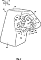
図1を参照すると、本発明の1つの実施形態のエアバッグモジュール10を側立面図が示している。エアバッグモジュール10は、補助席側の正面衝撃に対する保護を提供するように設計されている。しかしながら、他のタイプのエアバッグ、例えば、膝ボルスター、頭上エアバッグ、可膨張カーテン、可膨張構造補強材などにも等しく本発明を適用可能であることは当業者には理解できるであろう。 Referring to FIG. 1, a side elevation view shows an airbag module 10 of one embodiment of the present invention. The airbag module 10 is designed to provide protection against frontal impact on the auxiliary seat side. However, those skilled in the art will appreciate that the present invention is equally applicable to other types of airbags, such as knee bolsters, overhead airbags, inflatable curtains, inflatable structural reinforcements, and the like.
乗り物12は、長手方向14と横方向16と縦方向18とを有する。また、乗り物12は、図示したように、乗員22が座るシート20を有する。乗員22は、頭24と胴26と膝28とを有する。また、シートベルト30が乗員22に対する主要な拘束を提供する。また、乗り物12は、乗員22脇のフロントドア32と乗員22前方のフロントガラス24と該フロントガラス24の概ね下側に配置されたインストルメントパネル36とを有する。また、エアバッグモジュール10は、該エアバッグモジュール10が上面38から略上方へ飛び出るようにインストルメントパネル36の上面38内に収容されている。
The vehicle 12 has a
また、エアバッグモジュール10は、図示したように、クッション40を有し、ここでのクッション40は、完全に膨張せしめられた形で示されている。また、エアバッグモジュール10は、クッション40に膨張ガスを提供するようにインストルメントパネル36内に載置されたインフレータ42を有する。インフレータ42は、圧縮ガスインフレータ、火工インフレータ、そして、ハイブリッドインフレータを含む公知のタイプのものである。また、エアバッグモジュール10は、後述で詳細に説明するように膨張ガス流をクッション40に向けるようにクッション40内に配置された方向変更フード44を有する。
Moreover, the airbag module 10 has the
また、エアバッグモジュール10は、インストルメントパネル36内に配置されたハウジング46を有する。ハウジング46は、インストルメントパネル36内部の骨組みにアフィックスされている。また、インフレータ42は、ハウジング46にセキュアされており、クッション40と方向変更フード44とは、展開前は、ハウジング46によって画成される収容空間48内に収容されている。収容空間48は、インフレータ42からの膨張ガスがハウジング46から流出するためには方向変更フード44および/またはクッション40に流入しなければならないようにインフレータ42の外側にある。
Further, the airbag module 10 has a
また、乗り物12内には、電子制御装置50、すなわち、ECU50が配置されている。ECU50は、図示したように配置されている必要はなく、乗り物12内の様々な場所に配置可能である。また、ECU50は、ワイヤ52を介してインフレータ42に連結されている。また、ECU50には、ワイヤ56を介して加速度計54などの衝突センサが連結されている。加速度計54は、衝突が起こったこと或いは起ころうとしていることを示す信号をECU50に送信する。そして、ECU50は、インフレータ42の作動を起動させる信号をインフレータ42に送信する。そして、インフレータ42は、膨張ガスを排出してクッション40を膨張させる。
An electronic control device 50, that is, an ECU 50 is arranged in the vehicle 12. The ECU 50 does not have to be arranged as shown, and can be arranged at various locations in the vehicle 12. Further, the ECU 50 is connected to the inflator 42 via a
クッション40は、第1部分60を有し、この第1部分60は、図1に示した実施形態では、クッション40が膨張せしめられたときには上方に配置される。同様に、クッション40は、第1部分60の下側で乗員22の膝28に向って配置される第2部分62を有する。従来のデザインのエアバッグモジュールの幾つかでは、クッションの上方部分は、最初に膨張して乗員22の頭部24に接触して首に過剰な負荷をかけてしまう。一方、エアバッグモジュール10では、方向変更フード44が膨張ガスを第2部分62に向けて乗員22の体の大部分においてクッション40で衝撃を拡散する働きをする。
The
方向変更フード44は、インフレータ42からの膨張ガスを受け入れるためにハウジング46に隣接して入口部分64を有する。また、膨張ガスをクッション40内に排出するために入口部分64の略前方から後方にかけて出口部分66が配置されている。また、膨張中には、フロントガラス34に平行に並ぶようにして頂部部分68があり、この頂部部分68は、入口部分64と出口部分66との上方に配置される。また、頂部部分68は、方向変更フード44の大部分を有しているが、入口部分64と出口部分66とは、方向変更フード44の周辺に配置される比較的狭い領域である。
The redirecting
入口部分64は、該入口部分64の略後方に配置される放出開口70を有する。さらに、入口部分64は、該入口部分64の前方に補助放出開口72を有する。放出開口70は、補助放出開口72よりも相当に大きいので、膨張ガスの大部分を排出する。また、任意ではあるが、膨張ガスを横方向に排出してクッション40の横方向16への膨張を促進するために、方向変更フード44の頂部部分68の横に複数の通気孔74が設けられている。
The
放出開口70は、図示したように、膨張ガスを放出方向76に沿ってクッション40内へ排出する。放出方向76は、概ね、クッション40の第2部分62に向いているので、水平面78から角度80だけ下方を向いている。角度80は、約0度〜約145度の範囲である。より特定すると、角度80は、約30度〜約90度の範囲である。さらに特定すると、角度80は、約45度〜約85度の範囲である。さらに特定すると、角度80は、約60度〜約80度の範囲である。さらに特定すると、角度80は、約65度〜約75度の範囲であり、例えば、約70度である。
The
膨張ガスは、略上方を向いた膨張方向82に沿って方向変更フード44に流入する。また、頂部部分68は、図1に示したように、膨張ガスの大部分が方向転換路84に捕えられて該方向転換路84に沿って方向転換せしめられるように丸くなっている。また、頂部部分68は、略ドーム形の形状をしている。したがって、方向転換路84は、方向変更フード44を介した安定した流れを促進する比較的連続したカーブを有する。また、方向転換路84は、膨張ガスの流れの方向を膨張方向82から放出方向76に変える。なお、本明細書では、「略ドーム形」とは、連続的ではあるが外側へ弓状となるように径が変化する三次元的なカーブのある形状をいう。また、「略ドーム形」の形状は、球体の一部である必要はなく、さらに複雑な形状であってもよい。
The inflation gas flows into the
膨張ガスの一部は、クッション40の前方部分を充填するために前方へ延びる補助放出方向86に沿って補助放出開口72に流入する。補助放出開口72と通気孔74とは、膨張ガスの大部分が放出開口70を通って流出してクッション40の第2部分62に向うように放出開口70よりも幾分か小さい。なお、補助放出開口72や通気孔74は、任意的なものである。
A portion of the inflation gas flows into the auxiliary discharge opening 72 along the
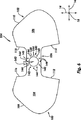
図2を参照すると、膨張中におけるクッション40と方向変更フード44とを破断斜視図が示している。クッション40は、図示したように、第1側部90と第2側部92とを有し、これら側部90,92は、長手方向14と横方向18とによって画成される互いに平行な面内において略鉛直方向を向いている。また、クッション40は、インストルメントパネル36の上面38(図2には示していない)に概ね沿うように配置される取付部分94を有する。また、方向変更フード44の入口部分64が取付部分94に取り付けられ、取付部分94が後述で詳細に説明するようにハウジング46に取り付けられる。なお、クッション40が従来公知の通気孔や紐やその他の特徴を有していてもよい。
Referring to FIG. 2, a broken perspective view shows the
また、方向変更フード44は、第1布部分100と第2布部分102とを有し、これら布部分100,102は、互いに一体的に形成されている(すなわち、1つの連続して広がる布から形成されている)。第1布部分100は、クッション40の第1側部90に隣接して該第1側部90に平行に延在して方向変更フード44の第1側部分104を画成している。同様に、第2布部分102は、クッション40の第2側部92に隣接して該第2側部92に平行に延在して方向変更フード44の第2側部分106を画成する。これら第1側部分104と第2側部分106と第1側部90と第2側部92とは、膨張中、幾分か弯曲しているが、それでもなお、互いに略平行となっている。したがって、「略平行」な部材は、必ずしも、平坦であったり、正確に平行であったりする必要はない。
Further, the
方向変更フード44の第1布部分100は、第1外側エッジ108を有し、第2布部分102は、第2外側エッジ110を有する。これら外側エッジ108,110は、放出か郁夫70と補助放出開口72との間に延在する。そして、これら外側エッジ108,110は、縫い合わせ、接着剤による接着、化学的な接着、高周波(RF)溶接、超音波溶接、ワンピース織り(OPW)、剛性のある機械的なファスナの利用などの方法によって互いに取り付けられる。図2に示した実施形態では、第1布部分100と第2布部分102とは、互いに縫い合わされて第1布部分100を第2布部分102に取り付ける継ぎ目11を形成している。
The
また、第1布部分100は、第1放出エッジ112と有し、第2布部分102は、第2放出エッジ114を有し、第1放出エッジ112は、第1外側エッジ108に隣接し、第2放出エッジ114は、第2外側エッジ110に隣接している。また、第1放出エッジ112と第2放出エッジ114とは、協力して放出開口70を画成する。また、図2に示した実施形態では、第1放出エッジ112と第2放出エッジ114とは、膨張の開始時に膨張ガスが放出開口70から自由に流れることができるように互いには取り付けられていない。
Also, the
同様に、第1布部分100は、第1補助放出エッジ116を有し、第2布部分102は、第2補助放出エッジ118を有し、第1補助放出エッジ116は、第1外側エッジ108に隣接し、第2補助放出エッジ118は、第2外側エッジ110に隣接している。したがって、第1外側エッジ108は、第1放出エッジ112と第1補助放出エッジ116との間にあり、第2外側エッジ110は、第2放出エッジ114と第2補助放出エッジ118との間にある。また、第1補助放出エッジ116と第2補助放出エッジ118とは、協力して膨張開始時に開いて膨張ガスを排出する補助放出開口72を画成する。
Similarly, the
方向変更フード44の見えている通気孔74は、図示したように、少なくとも部分的に横方向16に沿って延びる通気方向120に沿って膨張ガスを排出する。また、反対側にある通気孔74(図2では見えない)は、図示されている通気方向120の横方向成分とは略反対向きの横方向成分を有する通気方向に沿って膨張ガスを排出する。これら通気孔74は、クッション40の横方向の部分の膨張を促進し、これは、例えば、乗員22が一方の側または他方の側に傾いた場合における保護を高める。
The
エアバッグモジュール10の数々の要素は、広範な方法に従って製造可能であって組立可能である。以下、図3を参照して、こうした方法の1つを提示し説明する。 The numerous elements of the airbag module 10 can be manufactured and assembled according to a wide variety of methods. In the following, referring to FIG. 3, one such method is presented and described.
図3を参照すると、エアバッグモジュール122を分解されて組み立てられていない状態で斜視図が示している。組立が完了すると、エアバッグモジュール122は、図1および図2に示したエアバッグモジュール10となる。エアバッグモジュール122は、図示したように、方向変更フード44となるフードパネル124と、クッション40となるクッションパネル126とを有する。エアバッグモジュール122の他の特徴部分が隠れないように、図3には、クッションパネル126の取付部分94のみを示してある。また、エアバッグモジュール122は、保持リング130を有し、このリングリング130は、例えば、フードパネル124とクッションパネル126とハウジング46と入口42とを互いに取り付けるために複数のナット132に関連して使用されるものである。
Referring to FIG. 3, a perspective view is shown with the
また、図示したように、フードパネル124に第1布部分100と第2布部分102とが形成されており、これら布部分100,102は、中央細長片136によって互いに接続されている。また、第1布部分100と第2布部分102とは、例えば、広げられた布をフードパネル124の形状にレーザーカットすることによって中央細長片136に一体的に形成される。また、第1布部分100と第2布部分102との間のところで中央細長片136には、入口開口138が形成されている。また、中央細長片136は、入口開口138を包囲する周辺部分140を有する。
Further, as shown in the figure, a
また、周辺部分140周りには、径方向に対称的な形で複数の取付穴142が配設されている。また、周辺部分140周りには、複数の整列穴144も配設されている。図3に示した実施形態では、4つの取付穴142があり、対をなす取付穴142の隣接する2つの取付穴142間に、それぞれ、2つの整列穴144が配置されている。
A plurality of mounting
また、クッションパネル126は、例えば、一枚の広げられた布からクッションパネル126の形状をレーザーカットすることによって形成される。なお、これに代えて、複数の布片を互いに取り付けてクッションパネル126を形成してもよい。また、クッションパネル126は、従来公知の広範な様々な形状をとることができる。クッションパネル126の取付部分94は、周辺部分140によって包囲された同様に配置される入口開口138を有する。また、取付部分94の周辺部分140周りには、フードパネル124の中央細長片136の取付穴142および整列穴144に整列するように取付穴142と整列穴144とが配設されている。
The
保持リング130は、例えば、スチールまたはアルミニウムのような金属から形成され、或いは、任意ではあるが、プラスチック、セラミック、または、複合材料から形成される。図3に示した実施形態では、保持リング130は、管状壁146を有し、この管状壁146は、入口開口138を有し、この入口開口138は、フードパネル124の入口開口138とクッションパネル126の入口開口138とに大きさが略等しい。また、保持リング130は、フランジ150を有し、このフランジ150は、管状壁146から長手方向14で且つ横方向16に外方へと延びている。
The retaining
また、フードパネル124およびクッションパネル126の取付穴142に整列するように複数のファスナ152がフランジ150に取り付けられ或いは一体的に形成されている。ファスナ152は、フードパネル124に向って延びている。各ファスナ152は、例えば、ボルトやネジスタッドなどである。図3に示した実施形態では、フードパネル124およびクッションパネル126の周辺部分140にある取付穴142の数に一致するように、4つのファスナ152が設けられている。さらに、フランジ150には、例えば、打抜加工によって8つのタブ154が形成されている。タブ154は、フードパネル124およびクッションパネル126の周辺部分140の整列穴144に対応し、該整列穴144に整列する。
A plurality of
ハウジング46は、略直方体を画成する側壁156と、これら側壁156に略垂直に配置された取付プレート158とを有する。取付プレート158は、入口開口138を有し、この入口開口138は、保持リング130およびフードパネル124およびクッションパネル126の入口開口138に大きさが略等しい。また、取付プレート158は、該取付プレート158の入口開口138周りに配設された4つの取付穴142と8つの整列穴144とを有する。取付プレート158の取付穴142は、フードパネル124およびクッションパネルの取付穴142と保持リング130のファスナ152とに整列し、取付プレート158の整列穴144は、フードパネル124およびクッションパネルの整列穴144と保持リング130のタブ154とに整列する。
The
インフレータ42は、略円筒形の形状をしており、膨張ガスを排出する排気部分160と、ECU50(図3では見えない)に連結される接続部分162とを有する。排気部分160は、長手方向14で且つ横方向16に概ね沿って延びるフランジ164によって接続部分162から分離されている。フランジ164には、フードパネル124およびクッションパネル126およびハウジング46の取付穴142ならびに保持リング130のファスナ152に整列するように、複数の取付穴142が形成されている。
The inflator 42 has a substantially cylindrical shape, and includes an
また、インフレータ42が作動したときにインフレータ42の内部から膨張ガスを排出するために、インフレータ42の排気部分160には、複数の穴166が形成されている。これら穴166は、インフレータ42から膨張ガスを略径方向外方に排出して実質的にスラストが中立した展開を提供するような方向に向けられている。また、インフレータ42をECU50に連結するワイヤ52は、インフレータ42の接続部分162にあるレセプタ(図略)に押し込まれるコネクタ170を有する。
Further, a plurality of
また、エアバッグモジュール122は、図1および図2に示したエアバッグモジュール10を形成するように容易に組立可能である。1つの方法によれば、最初に、フードパネル124がクッションパネル126に取り付けられる。そして、フードパネル124およびクッションパネル126の入口開口138周りの周辺部分140が縫い合わされ(図略)、フードパネル124がクッションパネル126に取り付けられる。
Moreover, the
保持リング130とハウジング46とインフレータ42とが取り付けられる前に、フードパネル124とクッションパネル126とが閉じられ、方向変更フード44とクッション40とが形成される。詳細には、最初に、クッションパネル126のエッジ(図略)同士を縫い合わせることによってクッションパネル126が閉じられる。これは、従来公知の縫合せやその他の方法によって行われる。なお、本明細書では、「閉じる」は、空間を完全に包囲することを意味するのでも空間を気密に包囲することを意味するものでもない。
Before the retaining
なお、所望であれば、取付前にフードパネル124およびクッションパネル126の入口開口138からクッションパネル126のエッジを引っ張り出し、取付後に入口開口138に挿入して戻すようにしてもよく、これによれば、処理の完了時にクッションパネルのエッジが互いに向って内側にロールされて内部継ぎ目のところで取り付けられることになる。この構成は、継ぎ目の強度を大きくする。いずれにしても、クッション40は、方向変更フード44を形成するように閉じられていないフードパネル124を包囲することになる。
If desired, the edge of the
フードパネル124を閉じるためには、クッション40の外側から第1外側エッジ108と第2外側エッジ110とにアクセスできるように、最初に、クッション40およびフードパネル124の入口開口138から少なくとも部分的に第1布部分100と第2布部分102とを引っ張り出しておく。そして、第1外側エッジ108と第2外側エッジ110とが互いに縫い合わされ、継ぎ目111が形成される。上述したように、第1放出エッジ112と第2放出エッジ114と第1補助放出エッジ116と第2補助放出エッジ118とは、放出開口70および補助放出開口72を画成するように取り付けられていない状態とされている。
To close the
また、第1外側エッジ108と第2外側エッジ110とが互いに取り付けられた後、第1布部分100と第2布部分102とがクッション40および方向変更フード44の入口開口138に挿入されて戻される。こうして、方向変更フード44が表向きにされてクッション40内に配置される。ここで、第1外側エッジ100と第2外側エッジ102とは、互いに向って内方へと弯曲しており、継ぎ目111は、方向変更フード44内に配置されている。
Also, after the first
フードパネル124およびクッションパネル126が閉じられてクッション40および方向変更フード44が形成された後、クッション40および方向変更フード44の入口開口138に保持リング130が挿入される。そして、ファスナ152が方向変更フード44およびクッション40の取付穴142を通って延びると共にタブ154が方向変更フード44およびクッション40の整列穴144を通って延びるように、保持リング130が横方向18に沿って方向変更フード44およびクッション40に係合するように挿入される。
After the
また、ハウジング46とインフレータ42とが縦方向18に沿って挿入されて保持リング130に係合せしめられる。こうして、ファスナ152がフードパネル124およびクッションパネル126およびハウジング46およびインフレータ42の取付穴142を通って延在し、タブ154がフードパネル124およびクッションパネル126およびハウジング46の整列穴144を通って延在することになる。そして、ナット132がファスナ152の露出した端部に螺合されて係合せしめられ、これにより、フードパネル124およびクッションパネル126およびは46およびインフレータ42に対する保持リング130の係合が確実なものとされる。
Further, the
こうして、インフレータ42の排気部分160がハウジング46およびクッション40および方向変更フード44および保持リング130の入口開口138を通って延在することになる。したがって、排気部分160は、保持リング130の管状へ気146によって画成される空間内において方向変更フード44の内部に配置されることになる。また、管状壁146は、膨張ガスが排気部分160から流出する方向を制御するために、インフレータ42の排気部分160の穴166の幾つかを覆っている。穴166が対称的に覆われている限り、インフレータ42のスラスト中立状態が維持される。
Thus, the
そして、クッション40と方向変更フード44とがハウジング46内に折り畳まれる。この折畳は、例えば、自動化された機械作業や手作業によって行われる。なお、1つの実施形態として、クッション40および方向変更フード44が予め定められたパターンに従って折り畳まれるのではなく、単に、ハウジング46の内部の収容空間48内にコンパクトに詰め込まれてもよい。したがって、「折畳」との用語は、順序立てられた布コンパクト化技術と順序立てられていない布コンパクト化技術との両方を含むように大まかに使用される用語である。
Then, the
こうした順序立てられていない折畳は、例えば、「無秩序折畳」とも呼ばれ、複雑な折畳方法を実行するのに必要な機械作業やプロセスを排除することによってエアバッグモジュール10のコスト効率を向上させるものである。また、こうした折畳方法は、クッションの膨張経路を制御するためにエアバッグモジュールにおいて利用されることが多い。しかしながら、クッション40および方向変更フード44のコンパクト化が幾分か順序立てられていないときでさえ、エアバッグモジュール10の方向変更フード44は、上述したような制御を提供することができる。
Such unordered folds, for example, also referred to as “disordered folds”, make the air bag module 10 cost effective by eliminating the mechanical work and processes required to perform complex folding methods. It is to improve. Also, such a folding method is often used in an airbag module to control the inflation path of the cushion. However, even when the
また、別の実施形態として、クッション40および方向変更フード44がさらに順序立てられた方法に従って折り畳まれてもよい。こうした折畳は、所望であれば、ハウジング46およびインフレータ42が保持リング130に取り付けられる前に行われる。そして、クッション40と方向変更フード44とを備えた折り畳まれたパーッケージがハウジング46およびインフレータ42に連結される。なお、これに代えて、ハウジング46および/またはインフレータ42が保持リング130に対して位置決めされた後に順序立てられた折畳が行われてもよい。
As another embodiment, the
クッション40および方向変更フード44が収容空間48の形に折り畳まれた後は、エアバッグモジュール10は、乗り物12に直ぐにでも搭載可能な状態にある。そして、ワイヤ52がコネクタ170を介してインフレータ42の接続部分162に取り付けられる。そして、ハウジング46が様々な形態でインストルメントパネル36の内部に取り付けられる。
After the
衝突が検出されると、ECU50がワイヤ52を介して作動信号をインフレータ42に送信する。インフレータ42は、作動信号を受信し、作動して該インフレータ42の排気部分160の穴166から膨張ガスを排出する。膨張ガスは、概ね、方向変更フード44の頂部部分68に衝突してクッション40内で方向変更フード44を膨張させる。そして、膨張ガスの一部が方向転換経路84に沿って移動し、放出開口70を介して方向変更フード44から流出する。その他の膨張ガスは、図2に示したように、補助放出開口72を介して方向変更フード44から流出する。
When the collision is detected, the ECU 50 transmits an operation signal to the inflator 42 via the
展開中においては、方向変更フード44の頂部部分68は、図1に示したように、フロントガラス34に並んでいる。また、頂部部分68内の膨張ガスの圧力は、フロントガラス34によって反作用圧力が頂部部分68に加えられるにも係わらず、方向変更フード44の形状を維持する。したがって、方向変更フード44は、膨張中、一貫した全体形状を維持する。
During deployment, the
また、フロントガラス34は、頂部部分68が前方へ進むことを防止する。その結果、方向変更フード44は、膨張ガスが放出開口70から流出することによって加えられるスラスト力に反応して前方へと枢動することはできない。また、放出開口70は、望ましい形で放出方向に沿って膨張ガスを放出する所定の位置に維持される。なお、頂部部分68は、様々な乗り物の構成やフロントガラスの形状に合うように様々な形状に変わることができる。
The windshield 34 also prevents the
こうして、膨張ガスは、クッション40の第2部分62内へと向けられ、これにより、確実に、第2部分62が乗員22の頭部24および胴体26に衝撃に対する比較的均一な保護を提供するのに十分に即座に膨張する。なお、膨張中のクッション40の堅さを制限するために、クッション40が膨張中に限られた流量で該クッション40からガスを排出するように設計された通気孔またはガス透過性膜を有していてもよい。
Thus, the inflation gas is directed into the
本発明の別の実施形態では、膨張ガスの殆どがクッションに排出される前に方向変更フード44が適切に膨張することを確実ならしめるために、方向変更フード44からの膨張ガスの初期流量を制限することが望ましい。このことは、放出開口70が膨張ガスを放出方向76に沿って排出するのに適切な位置をとることを確実ならしめる。さらに、別の実施形態では、フードパネル134が捩れた状態におちいらないようにすることを確実ならしめるための対策をすることが好ましい。こうした別の実施形態は、図4および図5に示してあり、以下、これを図4および図5を参照して説明する。
In another embodiment of the present invention, the initial flow rate of inflation gas from the redirecting
図4を参照すると、本発明の別の実施形態の1つの方向変更フード244を斜視図が示している。方向変更フード244は、エアバッグモジュール10の残りの構成要素、または、上述した実施形態の構成要素とは異なって構成された構成要素と共に、方向変更フード44の代わりに使用される。また、方向変更フード244は、初期膨張段階中で示されている。
Referring to FIG. 4, a perspective view shows one
上述した実施形態と同様に、方向変更フード244は、該方向変更フード244から膨張ガスを流出させる入口部分64と、膨張ガスを方向転換させる頂部部分68とを有する。また、方向変更フード244は、後述するように、上述した実施形態のものとは幾分か異なって構成された出口部分266も有する。出口部分は、膨張ガスをクッション(図略)に排出する放出開口270と補助放出開口272とを有する。
Similar to the embodiment described above, the
また、方向変更フード244は、第1布部分300と第2布部分302とを有する。第1布部分300は、第1側部分304を有し、第2布部分は、第2側部分306を有し、これら側部分304,306は、通気孔74がない点で上述した実施形態の側部分104,106とは異なる。また、上述した実施形態のものと同様に、第1布部分300は、第1外側エッジ108を有し、第2布部分302は、第2外側エッジ110を有し、これら外側エッジ108,110同士は、継ぎ目111によって取り付けられている。
In addition, the
また、第1布部分300は、第1放出エッジ312を有し、第2布部分302は、第2放出エッジ314を有し、これら放出エッジ312,314は、協力して放出開口270を画成する。また、第1放出エッジ312および第2放出エッジ314は、継ぎ目315によって互いに取り付けられている点で上述した実施形態のものとは異なる。継ぎ目315は、方向変更フード244の内部と外部との間に予め定められた圧力差が存在するときに継ぎ目315が裂けて膨張ガスが放出開口270を介して方向変更フード244から流出することができるように選択された強度を有する。
Also, the
同様に、第1布部分300は、第1補助放出エッジ316を有し、第2布部分302は、第2補助放出エッジ318を有し、これら補助放出エッジ316,318は、協力して補助放出開口272を画成する。また、これら第1補助放出エッジ316と第2補助放出エッジ318とは、継ぎ目319によって互いに取り付けられており、この継ぎ目319は、予め定められた圧力差の形成に応答して該継ぎ目319が裂けて補助放出開口272を介して膨張ガスを排出することができるように選択された強度を有する。
Similarly, the
継ぎ目315,319を利用することは、大部分のガスがクッション内に排出される前に方向変更フード244が膨張ガスで実質的に満たされることを確実ならしめるのを助ける。したがって、放出開口270と補助放出開口272とは、これらが開いて膨張ガスを排出するときに適切に配置されていることになる。これによれば、初期段階において、膨張ガスは、方向変更フード244からのガス流が安定するまで予期していない方向へ方向変更フード244から流出するのではなく、所望の方向(例えば、図1に示されている放出方向76および補助放出方向86)に沿って流れる。
Utilizing
なお、継ぎ目315,319は、様々な多くの方法によって作製可能である。1つの方法によれば、方向変更フード244を備えたエアバッグモジュールは、方向変更フード44が閉じられるところまでは、上述した実施形態に関して説明したように組み立てられる。そして、方向変更フード244の外側エッジ108,110が単に縫い合わされるのではなく、放出エッジ312,314および補助放出エッジ316,318も縫い合わされる。
The
任意ではあるが、放出エッジ312,314および補助放出エッジ316,318が外側エッジ108,110を取り付けるのに利用されるプロセスをそのまま継続して利用して互いに取り付けられてもよい。また、継ぎ目111の破断強度よりも低い破断強度を提供するように継ぎ目315,319を形成するために、縫合せに関するパラメータ、例えば、糸の種類、縫い目の間隔などの1つ又はそれ以上を変更してもよい。或いは、継ぎ目315,319が継ぎ目111を形成するのに利用されるものとは異なる作業によって縫い合わされてもよい。なお、継ぎ目111,315,319が形成されると、方向変更フード244は、上述した実施形態に関して説明したように、クッション内に挿入されて戻され、表向きにされて配置される。
Optionally, discharge edges 312 and 314 and auxiliary discharge edges 316 and 318 may be attached to each other using the process utilized to attach
放出エッジ312,314および補助放出エッジ316,318の破断可能な取付は、方向変更フード244の不適切な閉鎖や搭載を防止するのを助けるという利点を追加する。すなわち、放出開口270および補助放出開口272が縫い合わされて閉じられた後は、第1布部分300および第2布部分302が放出開口270への予期していない挿入または補助放出開口272への予期していない挿入によって間違った安定状態へと捩れてしまうことはない。
The breakable attachment of the discharge edges 312, 314 and the auxiliary discharge edges 316, 318 adds the advantage of helping to prevent improper closure and mounting of the
さらに、放出エッジ312,314の形状およびサイズが補助放出エッジ316,318のものとは異なることから、第1布部分300と第2布部分302との不適切な取付は、即座に顕在化するし、修正可能である。したがって、放出エッジ312,314の1つが補助放出エッジ316,318に取り付けられていることは、即座に明らかとなる。
Further, improper attachment of the
図5を参照すると、本発明のさらに別の実施形態の方向変更フード344を斜視図が示している。方向変更フード344は、エアバッグモジュール10の残りの構成要素、または、第1実施形態のものとは異なって構成された構成要素と共に、方向変更フード44の代わりに利用される。また、方向変更フード344は、初期膨張段階中で示されている。
Referring to FIG. 5, a perspective view shows a
上述した実施形態と同様に、方向変更フード344は、膨張ガスを受け入れる入口部分64と、膨張ガスを方向転換させる頂部部分68とを有する。また、方向変更フード344は、膨張ガスをクッション(図略)内に排出する出口部分366も有する。出口部分366は、放出開口370と補助放出開口372とを有する。
Similar to the embodiment described above, the redirecting
また、方向変更フード344は、第1布部分400と第2布部分402とを有する。第1布部分400は、上述した実施形態のものと同様な第1側部分304を有する。同様に、第2布部分402は、第2側部分306を有する。また、上述した実施形態のものと同様に、第1布部分400は、第1外側エッジ108を有し、第2布部分402は、第2外側エッジ110を有する。これら第1外側エッジ108と第2外側エッジ110とは、継ぎ目111によって互いに取り付けられている。
In addition, the
また、第1布部分400は、第1放出エッジ412を有し、第2布部分402は、第2放出エッジ414を有し、これら放出エッジ412,414は、協力して放出開口370を画成する。また、第1放出エッジ412と第2放出エッジ414とは、事実上、概して破断不能な継ぎ目415によって互いに取り付けられている。また、第1布部分400は、第1補助放出エッジ416を有し、第2布部分402は、第2補助放出エッジ418を有し、これら補助放出エッジ416,418は、協力して補助放出開口372を画成する。また、第1補助放出エッジ416と第2補助放出エッジ418とは、これも破断不能な継ぎ目419な継ぎ目419によって互いに取り付けられている。
Also, the
また、出口部分366は、第2放出エッジ414に隣接した第2布部分402のところに形成された孔開き領域422を有する。孔開き領域422は、第2放出エッジ414に沿ったラインに配設された複数の孔424を有する。これら孔424は、該孔424に沿った孔開き領域422の破断強度が小さくなるように互いに離間して配置されている。したがって、孔開き領域422は、方向変更フード344の内部と外部との間の圧力差が予め定められた圧力差に達したときに裂けて開いて放出開口370を提供する。
The
同様に、出口部分366も、第2補助放出エッジ418に隣接した第2布部分402のところに形成された孔開き領域426を有する。孔開き領域426は、第2補助放出エッジ418に沿ったラインに配設された複数の孔428を有する。孔424と同様に、これら孔428も、該孔に沿った孔開き領域428の破断強度が小さくなるように互いに離間して配置されている。その結果、孔開き領域426は、予め定められた圧力差に達したときに裂けて開いて補助放出開口を提供する。
Similarly, the
これによれば、方向変更フード344は、上述した実施形態の利益に匹敵する利益を提供する。すなわち、放出開口370および補助放出開口372は、概して、膨張ガスの殆どがクッション内に排出される前に適切な位置に配置されていることになる。さらに、方向変更フード344の不適切な閉鎖や搭載は、困難であり、それに気付くのが比較的容易である。
According to this, the
また、継ぎ目415,419は、継ぎ目111を形成するのに利用される方法と同様な方法によって容易に作製可能である。継ぎ目415,419が継ぎ目111と同様に実質的に破断不能であることから、継ぎ目111,415,419は、パラメータを変更する必要なく、1つの連続した縫合せを使って形成可能である。したがって、外側エッジ108,110および放出エッジ412,414および補助放出エッジ416,418は、継ぎ目111,415,419が効果的に1つの連続した継ぎ目となるように連続的に互いに取り付けられる。
Further, the
また、孔424,428は、様々な方法によって形成可能である。1つの例として、孔424,428は、レーザーカットによって形成される。したがって、孔424,428は、方向変更フード344を形成するフードパネルの形状を画成するために外側エッジ108,110および放出エッジ412,414および補助放出エッジ416,418を形成するのに利用されるレーザーカット処理の一部として形成される。
The
特定の実施では、方向変更フードの一方の側を優先的に膨張させるために、横方向成分のある方向にガスの方向を変更させることが望ましい。こうした非対称な膨張は、フロントガラスやインストルメントパネルのカーブを補償したり、適所を外れた衝撃に対する保護を高めたりするために利用される。こうした横方向に非対称な膨張ガスの流れを提供するフードパネルの例は、図6に示してあり、次に図6を参照してこれを説明する。 In certain implementations, it is desirable to change the direction of the gas in a direction with a lateral component in order to preferentially expand one side of the direction change hood. This asymmetrical expansion is used to compensate for windshield and instrument panel curves and to increase protection against out-of-place impacts. An example of a hood panel that provides such a laterally asymmetric flow of inflation gas is shown in FIG. 6, which will now be described with reference to FIG.
図6を参照すると、本発明の別の実施形態の方向変更フードを作製するのに利用されるフードパネル524を平面図が示している。結果としてもたらされる方向変更フードは、クッション(図略)に排出される膨張ガスに横方向成分を提供するために、エアバッグモジュール10の残りの構成要素、または、第1実施形態のものとは異なって構成された構成要素と共に、方向変更フード44の代わりに利用される。
Referring to FIG. 6, a plan view illustrates a
フードパネル124と同様に、フードパネル524は、第1布部分100と、第2布部分102と、これら第1布部分100と第2布部分102とを互いに連結する中央細長片536とを有する。また、第1布部分100は、第1側部分104を有し、第2布部分102は、第2側部分106を有する。さらに、第1布部分100は、第1外側エッジ108と、第1放出エッジ112と、第1補助放出エッジ116とを有する。また、第2布部分102は、第2外側エッジ110と、第2放出エッジ114と、第2補助放出エッジ118とを有する。
Similar to the
中央細長片536は、膨張ガスをフードパネル124から形成された方向変更フードに流入させることができる入口開口138を有する。また、入口開口138を周辺部分540が包囲している。また、周辺部分540周りには、複数の取付穴142と整列穴144とが分布されている。これら取付穴142および整列穴144は、図3に示した実施形態のものと同様であり、図3に示した保持リング130のファスナ152およびタブ154と同様なファスナおよびタブを受容するのに利用される。
The
また、周辺部分540は、該周辺部分540の取付穴142および整列穴144が周辺部分140の取付穴および整列穴の位置から角度542だけ回転されている点で図3に示したフードパネル124の周辺部分140とは異なる。角度542は、排出される膨張ガスに横方向成分を与えるように選択される。なお、角度542が大きいと、より大きな横方向の流れとより大きな非対称性が提供される。図示したように、角度542は、図6に示した実施形態では、約20度である。
Also, the
角度542は、図1および図2に示したエアバッグモジュール10と構造的に同様なエアバッグモジュールを提供するようにフードパネル524をフードパネル124の代わりに利用可能とするという効果を奏する。しかしながら、フードパネル524の閉鎖によって形成される方向変更フード(図略)は、放出開口が乗り物の室内を向き且つ補助放出開口が乗り物の室外を向くように角度を付けられる。その結果、膨張ガスの殆どが乗り物の室内(例えば、図6で見て左方向への横方向16に沿って)であって且つ下方へ向けられる。
The
横方向への放出成分は、乗り物の中央では乗員に向って延在するが端部では後退するようにカーブしたインストルメントパネル(図略)を補償することを助ける。こうした形状のインストルメントパネルは、通常、補助席側のクッションを乗り物の室外に向って膨張させる。この効果は、角度542が存在することによって少なくとも部分的に打ち消される。また、他の実施形態として、中央のところで乗員から離れるようにカーブするフロントガラスを補償するために乗り物の室外に向う膨張ガス流を提供するために逆の角度を利用してもよい。
The laterally emitted component helps to compensate for an instrument panel (not shown) that curves towards the occupant in the middle of the vehicle but retracts at the end. The instrument panel having such a shape normally inflates the cushion on the side of the auxiliary seat toward the outside of the vehicle. This effect is at least partially counteracted by the presence of
なお、本明細書で広く説明し、特許請求の範囲に規定されているように、その構造、方法、または、その他の本質的な特徴から逸脱しない範囲で別の特定の形で本発明を実施可能である。上述した実施形態は、全ての観点で例示的なものであって限定的なものではない。したがって、本発明の範囲は、上の説明によってではなく特許請求の範囲によって規定されるものである。また、特許請求の範囲の均等の意味および範囲内での全ての変更も、本発明の範囲に含まれる。 It is noted that the invention may be embodied in other specific forms without departing from its structure, method, or other essential characteristics, as broadly described herein and defined in the claims. Is possible. The above-described embodiments are illustrative in all aspects and are not limiting. Accordingly, the scope of the invention is to be defined by the appended claims rather than by the foregoing description. Further, all modifications within the equivalent meaning and scope of the claims are also included in the scope of the present invention.
Claims (25)
該第1布部分が第1外側エッジを有し、上記第2布部分が第2外側エッジを有し、該第2外側エッジが前記第1外側エッジに取り付けられることで前記放出開口が画成されるエアバッグモジュール。An airbag module for protecting an occupant of a vehicle from an impact against a windshield, wherein the inflator and a first side part and the first side part are arranged to receive inflation gas from the inflator along an inflation direction. A cushion having a second side substantially parallel to one side and a direction change hood substantially composed of a single piece of fabric, the direction change hood receiving inflation gas from the inflator An inlet portion with an inlet opening arranged in a manner, a top portion arranged to restrict upward movement of the inflation gas and redirect the inflation gas downward in an angled discharge direction; An outlet portion with a discharge opening arranged to discharge gas into the cushion; a first fabric portion having a first side portion; and a second fabric portion having a second side portion. A, The first side portion and a first side and a Der substantially parallel to the second side of the cushion during inflation of the second side portion and said cushion is, the top portion of the vehicle during deployment A windshield is arranged to apply pressure to the top part,
The first fabric portion has a first outer edge, the second fabric portion has a second outer edge, and the second outer edge is attached to the first outer edge to define the discharge opening. air bag module to be.
Applications Claiming Priority (3)
| Application Number | Priority Date | Filing Date | Title |
|---|---|---|---|
| US10/655,456 US7195279B2 (en) | 2003-09-04 | 2003-09-04 | Gas flow deflection apparatus and method for airbag systems |
| US10/655,456 | 2003-09-04 | ||
| PCT/US2004/028457 WO2005025946A2 (en) | 2003-09-04 | 2004-09-01 | Gas flow deflection apparatus and method for airbag systems |
Publications (3)
| Publication Number | Publication Date |
|---|---|
| JP2007504047A JP2007504047A (en) | 2007-03-01 |
| JP2007504047A5 JP2007504047A5 (en) | 2007-10-11 |
| JP4980056B2 true JP4980056B2 (en) | 2012-07-18 |
Family
ID=34226145
Family Applications (1)
| Application Number | Title | Priority Date | Filing Date |
|---|---|---|---|
| JP2006525414A Expired - Fee Related JP4980056B2 (en) | 2003-09-04 | 2004-09-01 | Gas flow direction changing apparatus and gas flow direction changing method for airbag system |
Country Status (4)
| Country | Link |
|---|---|
| US (1) | US7195279B2 (en) |
| EP (1) | EP1660355B1 (en) |
| JP (1) | JP4980056B2 (en) |
| WO (1) | WO2005025946A2 (en) |
Families Citing this family (50)
| Publication number | Priority date | Publication date | Assignee | Title |
|---|---|---|---|---|
| US7398992B2 (en) * | 2003-11-18 | 2008-07-15 | Tk Holdings Inc. | Air bag |
| US7556290B2 (en) | 2006-09-27 | 2009-07-07 | Autoliv Asp, Inc. | Airbag cushion with a laced vent to optionally vent gas for out-of-position conditions |
| US7614653B2 (en) | 2006-09-27 | 2009-11-10 | Autoliv Asp, Inc. | Pre-folded airbag cushion with optional venting for out-of-position conditions |
| US7722080B2 (en) | 2006-09-27 | 2010-05-25 | Autoliv Asp, Inc. | Airbag cushion with a flap vent to optionally vent gas for out-of-position conditions |
| US7597355B2 (en) | 2004-04-27 | 2009-10-06 | Autoliv Asp, Inc. | Airbag cushions with optional venting for out-of-position conditions |
| US7614654B2 (en) * | 2005-12-07 | 2009-11-10 | Autoliv Asp, Inc. | Airbag cushion with diffuser with cinch tube to vent gas for out-of-position conditions |
| US7445238B2 (en) * | 2005-05-06 | 2008-11-04 | Tk Holdings Inc. | Occupant protection apparatus |
| US8168133B2 (en) * | 2005-05-09 | 2012-05-01 | Wisconsin Alumni Research Foundation | Device for performing a high throughput assay |
| US7497468B2 (en) * | 2005-05-12 | 2009-03-03 | Autoliv Asp, Inc. | Airbag inflation deflection module |
| US7568729B2 (en) | 2005-12-07 | 2009-08-04 | Autoliv Asp, Inc. | Locking mechanism for a cinch tube of an airbag cushion |
| US7618060B2 (en) * | 2006-03-22 | 2009-11-17 | Trw Vehicle Safety Systems Inc. | Air bag module with an integral shield |
| US20070284864A1 (en) * | 2006-06-08 | 2007-12-13 | Trw Vehicle Safety Systems Inc. | Inflatable vehicle occupant protection device construction |
| US7748738B2 (en) | 2006-09-27 | 2010-07-06 | Autoliv Asp, Inc. | Airbag cushion with adaptive diffuser for out-of-position conditions |
| JP5286673B2 (en) * | 2007-02-19 | 2013-09-11 | タカタ株式会社 | Air bag and air bag device |
| WO2008130287A1 (en) * | 2007-04-23 | 2008-10-30 | Autoliv Development Ab | Air-bag with gas deflector |
| DE202007007355U1 (en) * | 2007-05-22 | 2007-09-06 | Takata-Petri Ag | Gas flow distributor for a gas bag module |
| US7597356B2 (en) | 2007-06-05 | 2009-10-06 | Autoliv Asp, Inc. | Airbag cushions with gas deflectors and optional venting for out-of-position conditions |
| US7770926B2 (en) | 2007-08-09 | 2010-08-10 | Autoliv Asp, Inc. | Airbag adaptive venting for out-of-position occupants |
| US8191925B2 (en) * | 2008-04-14 | 2012-06-05 | Autoliv Asp, Inc. | Dynamic safety vent |
| US7862082B2 (en) * | 2008-08-20 | 2011-01-04 | Gm Global Technology Operations, Inc. | Air bag inflation baffle |
| US7950688B2 (en) * | 2008-09-17 | 2011-05-31 | Tk Holdings Inc. | Airbag module |
| US7938445B2 (en) | 2009-03-03 | 2011-05-10 | Autoliv Asp, Inc. | Dual chamber airbag cushions with a safety vent in the front chamber |
| US7946613B2 (en) * | 2009-03-03 | 2011-05-24 | Autoliv Asp, Inc. | Dual chamber airbag cushion |
| DE102009018159A1 (en) | 2009-04-21 | 2010-11-04 | Autoliv Development Ab | Airbag module with an adaptive ventilation opening having gas bag |
| JPWO2010122835A1 (en) * | 2009-04-24 | 2012-10-25 | 本田技研工業株式会社 | Airbag device |
| EP2457782B1 (en) * | 2009-07-24 | 2014-02-19 | Toyota Jidosha Kabushiki Kaisha | Airbag device |
| US8226118B2 (en) * | 2009-08-05 | 2012-07-24 | Autoliv Asp, Inc. | Safety venting with passively closeable vents |
| JP5641637B2 (en) * | 2009-12-23 | 2014-12-17 | タカタ株式会社 | Air bag and air bag device |
| KR101219694B1 (en) * | 2010-08-30 | 2013-01-18 | 현대자동차주식회사 | Airbag apparatus for vehicle |
| US8684404B2 (en) * | 2010-10-27 | 2014-04-01 | Trw Vehicle Safety Systems Inc. | Air bag with variable venting |
| US8696022B2 (en) * | 2010-10-27 | 2014-04-15 | Trw Vehicle Safety Systems Inc. | Air bag with variable venting |
| US8684407B2 (en) * | 2010-10-27 | 2014-04-01 | Trw Vehicle Safety Systems Inc. | Air bag with height adaptive tether |
| JP5649983B2 (en) * | 2011-01-07 | 2015-01-07 | タカタ株式会社 | Air bag and air bag device |
| JP5652784B2 (en) * | 2011-01-14 | 2015-01-14 | タカタ株式会社 | Air bag and air bag device |
| DE102011112882A1 (en) * | 2011-09-08 | 2013-03-14 | Daimler Ag | Airbag, in particular for a motor vehicle |
| JP5790354B2 (en) * | 2011-09-13 | 2015-10-07 | タカタ株式会社 | Passenger seat airbag, passenger seat airbag apparatus and vehicle |
| JP5766577B2 (en) * | 2011-10-20 | 2015-08-19 | 芦森工業株式会社 | Airbag device |
| US8646808B2 (en) | 2012-06-18 | 2014-02-11 | Autoliv Asp, Inc. | Airbag with active vent |
| US8882143B2 (en) | 2013-02-08 | 2014-11-11 | Autoliv Asp, Inc. | Airbag with slit vent |
| US20140276294A1 (en) * | 2013-03-15 | 2014-09-18 | Compression Therapy Concepts, Inc. | Multiple Bladder Deep Vein Thrombosis Prevention Garment |
| EP2905185B1 (en) | 2014-02-06 | 2018-03-14 | Autoliv Development AB | Motor vehicle with an airbag between a wheel and the car body and airbag unit |
| GB2524292A (en) * | 2014-03-19 | 2015-09-23 | Ford Global Tech Llc | An airbag system |
| CN105235630A (en) * | 2015-10-21 | 2016-01-13 | 芜湖金鹏汽车部件有限公司 | Buffer type automobile airbag |
| US10093270B2 (en) | 2016-01-13 | 2018-10-09 | Autoliv Asp, Inc. | Multi-flap vents for inflatable chambers |
| JP2017132313A (en) * | 2016-01-26 | 2017-08-03 | タカタ株式会社 | Air bag and air bag device |
| KR101776510B1 (en) * | 2016-06-22 | 2017-09-08 | 현대자동차주식회사 | Front airbag for vehicle |
| CN111094078B (en) * | 2017-10-05 | 2024-02-13 | 奥托立夫开发公司 | Airbag device |
| CN108891378B (en) * | 2018-08-28 | 2023-05-30 | 延锋汽车智能安全系统有限责任公司 | Safety airbag with flow guiding device |
| US11180103B2 (en) | 2019-10-28 | 2021-11-23 | Autoliv Asp, Inc. | Frontal airbag systems |
| US11292423B2 (en) | 2020-05-18 | 2022-04-05 | Autoliv Asp, Inc. | Vent flap for airbag assemblies |
Family Cites Families (19)
| Publication number | Priority date | Publication date | Assignee | Title |
|---|---|---|---|---|
| US4265468A (en) | 1979-07-03 | 1981-05-05 | General Motors Corporation | Inflatable restraint system |
| US5160164A (en) | 1991-06-05 | 1992-11-03 | Trw Vehicle Safety Systems Inc. | Gas deflection device for an air bag assembly |
| JP2754979B2 (en) * | 1991-10-17 | 1998-05-20 | 日産自動車株式会社 | Automotive airbag device |
| JP3245934B2 (en) | 1992-03-18 | 2002-01-15 | タカタ株式会社 | Airbag device for passenger seat |
| CA2108394A1 (en) | 1992-12-01 | 1994-06-02 | Thomas M. Kriska | Air bag cushion with fabric diffuser |
| US5282646A (en) | 1993-02-16 | 1994-02-01 | General Motors Corporation | Multi-chamber air bag with displacement responsive valve |
| DE4442118B4 (en) * | 1993-11-26 | 2004-07-01 | Toyoda Gosei Co., Ltd., Nishikasugai | air bag |
| JP3697742B2 (en) * | 1995-04-28 | 2005-09-21 | 豊田合成株式会社 | Airbag device for passenger seat |
| JPH1044914A (en) * | 1995-08-11 | 1998-02-17 | Denso Corp | Air bag device for front passenger seat |
| US5951038A (en) * | 1995-08-11 | 1999-09-14 | Denso Corporation | Air bag device having inner and outer bags for selectively directed expansion thereof |
| DE19611541C2 (en) * | 1996-03-23 | 1999-05-20 | Daimler Benz Ag | Airbag for motor vehicles |
| DE29606709U1 (en) | 1996-04-12 | 1996-08-08 | Trw Repa Gmbh | Gas bag |
| JPH10203280A (en) * | 1997-01-20 | 1998-08-04 | Toyo Tire & Rubber Co Ltd | Air bag device for front passenger seat |
| JPH10226294A (en) * | 1997-02-17 | 1998-08-25 | Toyo Tire & Rubber Co Ltd | Air bag for vehicle |
| JPH11198750A (en) * | 1998-01-16 | 1999-07-27 | Takata Kk | Air bag device for front passenger's seat |
| JP2000043663A (en) * | 1998-07-31 | 2000-02-15 | Kansei Corp | Airbag system for vehicle |
| DE10060667B4 (en) * | 1999-12-07 | 2006-04-13 | Toyoda Gosei Co., Ltd. | Three-dimensional airbags for motor vehicles |
| JP4232313B2 (en) * | 2000-03-23 | 2009-03-04 | 豊田合成株式会社 | Airbag manufacturing method |
| US6669229B2 (en) | 2001-03-22 | 2003-12-30 | General Motors Corporation | Automotive vehicle air bag system |
-
2003
- 2003-09-04 US US10/655,456 patent/US7195279B2/en not_active Expired - Fee Related
-
2004
- 2004-09-01 EP EP04782869A patent/EP1660355B1/en not_active Expired - Lifetime
- 2004-09-01 JP JP2006525414A patent/JP4980056B2/en not_active Expired - Fee Related
- 2004-09-01 WO PCT/US2004/028457 patent/WO2005025946A2/en active Application Filing
Also Published As
| Publication number | Publication date |
|---|---|
| US7195279B2 (en) | 2007-03-27 |
| EP1660355B1 (en) | 2011-12-07 |
| US20050052008A1 (en) | 2005-03-10 |
| JP2007504047A (en) | 2007-03-01 |
| EP1660355A2 (en) | 2006-05-31 |
| WO2005025946A3 (en) | 2005-07-28 |
| WO2005025946A2 (en) | 2005-03-24 |
Similar Documents
| Publication | Publication Date | Title |
|---|---|---|
| JP4980056B2 (en) | Gas flow direction changing apparatus and gas flow direction changing method for airbag system | |
| JP4848141B2 (en) | Airbag device | |
| US7380822B2 (en) | Airbag and airbag apparatus | |
| EP0897352B1 (en) | Air bag with externally mounted tether | |
| EP0739784B1 (en) | Airbag with variable deployment modes | |
| US5454595A (en) | Hidden volume cushion | |
| JP6726057B2 (en) | Airbag device | |
| EP1555168B1 (en) | Leg-protection device for vehicle occupant | |
| JP4569310B2 (en) | Knee airbag device for vehicle | |
| JP2005503287A (en) | Bumper airbag and its system | |
| JPH10203294A (en) | Seamless side expansion type constraint development system | |
| KR20120099012A (en) | Airbag device | |
| JP7395726B2 (en) | frontal airbag system | |
| JP6941177B2 (en) | Airbag device for saddle-riding vehicles | |
| US10829080B2 (en) | Air bag device | |
| JP5187818B2 (en) | Air bag device for knee protection | |
| JP4836494B2 (en) | Airbag device | |
| JP2008230520A (en) | Air bag device for vehicle outside | |
| JP2003011871A (en) | Airbag device for saddle type vehicle | |
| JP2002104120A (en) | Air bag device for automobile | |
| US20210122317A1 (en) | Driver airbag | |
| US5516146A (en) | Fastenerless airbag mounting | |
| JP4433078B2 (en) | Knee airbag device for vehicle | |
| JP4608551B2 (en) | Side airbag module for automobile | |
| JP2000247199A (en) | Air bag device |
Legal Events
| Date | Code | Title | Description |
|---|---|---|---|
| A521 | Request for written amendment filed |
Free format text: JAPANESE INTERMEDIATE CODE: A523 Effective date: 20070823 |
|
| A621 | Written request for application examination |
Free format text: JAPANESE INTERMEDIATE CODE: A621 Effective date: 20070823 |
|
| A131 | Notification of reasons for refusal |
Free format text: JAPANESE INTERMEDIATE CODE: A131 Effective date: 20100406 |
|
| A601 | Written request for extension of time |
Free format text: JAPANESE INTERMEDIATE CODE: A601 Effective date: 20100705 |
|
| A602 | Written permission of extension of time |
Free format text: JAPANESE INTERMEDIATE CODE: A602 Effective date: 20100712 |
|
| A521 | Request for written amendment filed |
Free format text: JAPANESE INTERMEDIATE CODE: A523 Effective date: 20101006 |
|
| A131 | Notification of reasons for refusal |
Free format text: JAPANESE INTERMEDIATE CODE: A131 Effective date: 20110405 |
|
| A601 | Written request for extension of time |
Free format text: JAPANESE INTERMEDIATE CODE: A601 Effective date: 20110705 |
|
| A602 | Written permission of extension of time |
Free format text: JAPANESE INTERMEDIATE CODE: A602 Effective date: 20110712 |
|
| TRDD | Decision of grant or rejection written | ||
| A01 | Written decision to grant a patent or to grant a registration (utility model) |
Free format text: JAPANESE INTERMEDIATE CODE: A01 Effective date: 20120403 |
|
| A01 | Written decision to grant a patent or to grant a registration (utility model) |
Free format text: JAPANESE INTERMEDIATE CODE: A01 |
|
| A61 | First payment of annual fees (during grant procedure) |
Free format text: JAPANESE INTERMEDIATE CODE: A61 Effective date: 20120418 |
|
| FPAY | Renewal fee payment (event date is renewal date of database) |
Free format text: PAYMENT UNTIL: 20150427 Year of fee payment: 3 |
|
| R150 | Certificate of patent or registration of utility model |
Free format text: JAPANESE INTERMEDIATE CODE: R150 |
|
| R250 | Receipt of annual fees |
Free format text: JAPANESE INTERMEDIATE CODE: R250 |
|
| R250 | Receipt of annual fees |
Free format text: JAPANESE INTERMEDIATE CODE: R250 |
|
| R250 | Receipt of annual fees |
Free format text: JAPANESE INTERMEDIATE CODE: R250 |
|
| LAPS | Cancellation because of no payment of annual fees |