EP0897352B1 - Air bag with externally mounted tether - Google Patents
Air bag with externally mounted tether Download PDFInfo
- Publication number
- EP0897352B1 EP0897352B1 EP97924539A EP97924539A EP0897352B1 EP 0897352 B1 EP0897352 B1 EP 0897352B1 EP 97924539 A EP97924539 A EP 97924539A EP 97924539 A EP97924539 A EP 97924539A EP 0897352 B1 EP0897352 B1 EP 0897352B1
- Authority
- EP
- European Patent Office
- Prior art keywords
- air bag
- tether
- tether means
- occupant
- housing
- Prior art date
- Legal status (The legal status is an assumption and is not a legal conclusion. Google has not performed a legal analysis and makes no representation as to the accuracy of the status listed.)
- Expired - Lifetime
Links
Images


Classifications
-
- B—PERFORMING OPERATIONS; TRANSPORTING
- B60—VEHICLES IN GENERAL
- B60R—VEHICLES, VEHICLE FITTINGS, OR VEHICLE PARTS, NOT OTHERWISE PROVIDED FOR
- B60R21/00—Arrangements or fittings on vehicles for protecting or preventing injuries to occupants or pedestrians in case of accidents or other traffic risks
- B60R21/02—Occupant safety arrangements or fittings, e.g. crash pads
- B60R21/16—Inflatable occupant restraints or confinements designed to inflate upon impact or impending impact, e.g. air bags
- B60R21/20—Arrangements for storing inflatable members in their non-use or deflated condition; Arrangement or mounting of air bag modules or components
- B60R21/201—Packaging straps or envelopes for inflatable members
-
- B—PERFORMING OPERATIONS; TRANSPORTING
- B60—VEHICLES IN GENERAL
- B60R—VEHICLES, VEHICLE FITTINGS, OR VEHICLE PARTS, NOT OTHERWISE PROVIDED FOR
- B60R21/00—Arrangements or fittings on vehicles for protecting or preventing injuries to occupants or pedestrians in case of accidents or other traffic risks
- B60R21/02—Occupant safety arrangements or fittings, e.g. crash pads
- B60R21/16—Inflatable occupant restraints or confinements designed to inflate upon impact or impending impact, e.g. air bags
- B60R2021/161—Inflatable occupant restraints or confinements designed to inflate upon impact or impending impact, e.g. air bags characterised by additional means for controlling deployment trajectory
Definitions
- the present invention generally relates to an occupant safety restraint device and more particularly to an air bag module with an externally mounted tether which controls the inflation trajectory of an inflating air bag.
- tethers When an air bag is inflated it is propelled rapidly toward the occupant.
- tethers In order to reduce the forward velocity of the air bag relative to the occupant, tethers have been incorporated internal to the air bag.
- the tether in addition to controlling the forward relative velocity of the inflating air bag, also controls its inflation shape and inflation trajectory.
- US-A-3,879,056 discloses an air bag comprising a restraining element provided inside the air bag structure and having a frangible portion.
- the restraining element ruptures and the pressure within the air bag decreases, thus the rebound of the occupant is remarkably decreased.
- the restraining member is provided outside the air bag, but in each of the disclosed embodiments the frangible portion does not break when the air bag inflates: the rupture occurs only when the occupant hits the air bag.
- US-A-5,004,266, on which the preamble of claim 1 is based discloses an air bag including a steel band wrapped around the folded cushion of the air bag.
- the band includes tapered portions which are asymmetrically arranged to form a narrow width, frangible, juncture.
- the aim of this band is to initially force the air bag to deploy laterally or parallel to the occupant.
- a problem with this type of embodiments is that the speed of deployment towards the occupant is nil during the initial stage of inflation, and suddenly increases after the rupture of the restraining bag, resulting in a bad control of the deployment step.
- the external tether comprises a loop formed of a single piece of air bag material enveloping the folded air bag whereby the two panels are joined together by either sewing or bonding.
- the band is formed by joining two pieces of material by sewing or bonding. The bonding of the two panels can be obtained through numerous methods such as heat application, adhesives, and ultrasonic welding. Any reference to stitching or bonding will be considered as joining.
- Various other embodiments of the tether are also shown.
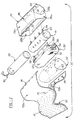
- FIGURE 1 illustrates an air bag module generally shown by numeral 22.
- the module includes a housing 24 of known variety having a plurality of sides 26a and 26b, and ends 28a and 28b defining an open sided or top, walled portion 30.
- the interior of the housing defines a cavity 32.
- the inflator 40 is of known construction and includes a pyrotechnic squib or initiator that is activated upon receipt of an electric activation signal via wires 42.
- the inflator may be supported within a hollow manifold 41 (as is the case with a hybrid inflator) having a plurality of threaded studs 44 which are received through a respective corresponding opening 46 within a lower portion 48 of the housing.
- the module 22 additionally includes an air bag 50 of known construction having a cushion portion 52 which when inflated envelopes and protects the occupant.
- the cushion portion extends from a neck portion 54 which includes a plurality of flaps 56a and 56b, each of the flaps includes a plurality of stud holes such as 58 which are used to mount the air bag 50 onto the inflator or manifold, as the case may be, within the housing.
- the flaps 56a and 56b are overlapped about a rear portion 60 of the manifold with each of the studs 44 extending through a corresponding one of the stud holes 58 in each of the flaps 56a and 56b.
- the cushion portion 52 of the air bag is folded into a compact configuration and maintained in such a configuration with a tearable loop of material 62 such as Tyvek as used in the prior art.
- This loop of material also includes a plurality of stud holes which are overlapped about the manifold.
- the tearable loop 62 may include one or more perforation lines 63 which are torn as the air bag inflates.
- the inflator is pressed into the manifold and aligned such that both ends of the inflator are even with the ends of the manifold.
- the air bag cushion 50, the tearable loop of material 62, and the external tether 70 are assembled onto the manifold.
- the manifold with the above components is inserted through an opening in the housing 30, and the studs 44 are aligned with the openings 46, and fastened together.
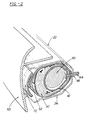
- FIGURE 2 illustrates a cross-sectional view of the assembled module 22 with a deployable cover 63 showing the air bag 50 folded about the manifold 41 and held thereto by the tearable material 62 with the studs extending through the openings 46 within the housing.
- An external tether 70 is positioned external to the tearable material 62, and engaged with the studs.
- a deployable cover 63 is attached to the housing 24 to protect the air bag 50. The cover is moved away from the housing by the air bag as it inflates.
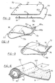
- FIGUREs 3 and 5 illustrate one embodiment of an external tether generally shown as 70.
- the tether 70 is also shown in FIGUREs 1 and 2.
- the illustrated tether comprises two pieces of material overlaid to form panels 72a and 72b having stud holes or openings 74 near its ends. As can be seen each panel has sides 73. The number and spacing of the openings 74 correspond to the number and spacing of the studs 42. The right hand ends of the two panels are joined such as by sewing or bonding throughout an area generally shown by numeral 75.
- the panels 72a and 72b are overlaid such that the openings 74 in each panel are registered on to the other, yielding the configuration illustrated in FIGURE 5.
- the tether 70 is formed into a looped portion 90 and a joined-together portion 91 by fabricating within each of the panels 72a and 72b a plurality of breakable or frangible stitches or bond 76.
- the area identified as 75 represents the region of the portion 91 of the panels 72a,b whereby either stitches or an alternative joining technique is used.
- the plurality of stitches / bonds 76 provides a means for retarding the forward motion of the cushion portion 52 of the air bag 50 while encouraging lateral inflation.
- the advantage achieved by utilizing the two-piece construction is one of improved reinforcement at the location of the stud holes 74 during deployment. It can be appreciated that additional reinforcements can be incorporated in all embodiments of the design.
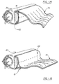
- the tether 70 is constructed from a single piece of material (see FIGURE 4) having a single set of openings 74 formed therein and overlapping panels 72a,b.
- each panel or portion 72a and 72b is generally chosen to be approximately equal to the width open top of the housing.
- the length of each of the first and second portions 72a and 72b that is the length generally measured from the openings 74 to the ends 80a and 80b, is generally chosen to be dependent upon the size of the inflated air bag and the sustained level of retarding force desired to retard the forward motion of the air bag.
- the length of the panel (or half of the tether shown in FIGURE 4) should be adequate to affix the openings 74 to the studs 44 and to permit the panels 72a and 72b to wrap around the tearable material 62, and manifold/inflator.
- the panels 72a and 72b generally meet in the center of the opening 30 of the housing 24 generally above the perforation line of the tearable loop 62.
- the joined panels incorporate a tear stitch offset 81 (see Figure 6).
- This offset 81 provides additional length or slack between the exterior surface of the tearable material 62 (i.e. the compacted position of the air bag 50) and the first set of stitches (or initial edge of the bond) 92 of the tear stitches/bond 76.
- This slack permits the air bag to expand unobstructedly from the housing and thereafter expand laterally.
- the off-set 81 need not be centered about the opening 30 of the housing nor do the initial lines of stitches nor the initial bond line of the bonded panels need to be centered.
- FIGURE 14 shows the offset 81 and the initial line of stitches/bonding proximate the upper side of the opening 30 and FIGURE 15 shows the off-set and stitches/bonding proximate the lower side of the opening.
- This positioning and subsequent joining of the two panels can also be positioned in the full range between the top and bottom of the housing.
- FIGUREs 6 and 7 are views showing the orientation of the tether 70 and its panels 72a and 72b about the housing 24 and the tearable material 62.
- the openings 74 of the tether are received about the studs.
- the manifold or inflator is secured to the housing by a plurality of nuts 96 (see FIGURE 8) received about a corresponding stud 44.
- the inflator 40 Upon receipt of a signal indicative of a crash, the inflator 40 is activated releasing or generating inflation gas. This gas enters the folded cushion 52. As the cushion expands outwardly its forward motion (through the stitch offset 81 if used) is resisted by the joined area 75 holding the panels 72a and 72b of the tether together. As a greater amount of inflation gas enters the cushion, the cushion simultaneously pushes forward breaking individual stitches (or separating the bonds), enlarging the loop portion 90 of the tether. With the forward motion of the air bag restricted due to action of the plurality of stitches 76 or bonded regions, the cushion 52 will expand laterally out from the housing 24 (see FIGURE 7) through the open sides 73 of the looped portion 90 of the tether 70. As the cushion is urged forwardly against the restraining force of the stitches or bonded regions, the panels 72a,b open a greater amount until the cushion 52 is completely inflated and all of the joined areas are opened. This configuration is illustrated in FIG
- FIGURES 9-13 show top views of alternate embodiments of a tether.
- Each alternate tether can be constructed from a single piece of material such as shown in FIGURE 4 or two pieces of material such as shown in FIGURE 3.
- FIGURE 9 shows a tether 70a having its two tether portions 72a,b having an arcuate cut-out 100.
- One or two sets of openings 74 will be used depending on whether one or two panels 72 is used.
- the cut-out 100 is positioned just forward of the housing 24.
- FIGURE 6 shows in phantom line the general location of the cut-out 100. As can be seen this cut-out narrows the width of the panels 72a,b which will encourage the air bag to inflate laterally as less material is restricting its motion.
- FIGURE 10 shows another embodiment of a tether 70b in which the sides of each portion 72a,b have a cut-out 100a formed by straight lines.
- FIGURE 11 shows a tether 70c having a generally trapezoidal shape while FIGURE 12 shows an oval/oblong tether 70d.
- the tether 70d of FIGURE 13 has its panels 72a,b formed as a plurality of extending, separated fingers 102a-c.
- the tether panels 72a,b are constructed of air bag material, it is not necessarily a requirement of the invention in that the tether can be constructed of a plurality of strips of woven seat belt material (similar to the configuration shown in FIGURE 13 but without the mutual connection), in which case the width of each tether would be approximately 25-75mm. Additionally, the tether can be constructed of any material that lends itself to bonding, such as nylon woven material, a plastic laminate or film. As can be appreciated each of the above alternate tether embodiments can be sewn or bonded together.
Landscapes
- Engineering & Computer Science (AREA)
- Mechanical Engineering (AREA)
- Air Bags (AREA)
Abstract
Description
- The present invention generally relates to an occupant safety restraint device and more particularly to an air bag module with an externally mounted tether which controls the inflation trajectory of an inflating air bag.
- When an air bag is inflated it is propelled rapidly toward the occupant. In order to reduce the forward velocity of the air bag relative to the occupant, tethers have been incorporated internal to the air bag. The tether, in addition to controlling the forward relative velocity of the inflating air bag, also controls its inflation shape and inflation trajectory.
- US-A-3,879,056 discloses an air bag comprising a restraining element provided inside the air bag structure and having a frangible portion. When after a crash an occupant hits the inflated air bag, the restraining element ruptures and the pressure within the air bag decreases, thus the rebound of the occupant is remarkably decreased. In one case the restraining member is provided outside the air bag, but in each of the disclosed embodiments the frangible portion does not break when the air bag inflates: the rupture occurs only when the occupant hits the air bag.
- US-A-5,004,266, on which the preamble of
claim 1 is based, discloses an air bag including a steel band wrapped around the folded cushion of the air bag. The band includes tapered portions which are asymmetrically arranged to form a narrow width, frangible, juncture. The aim of this band is to initially force the air bag to deploy laterally or parallel to the occupant. A problem with this type of embodiments is that the speed of deployment towards the occupant is nil during the initial stage of inflation, and suddenly increases after the rupture of the restraining bag, resulting in a bad control of the deployment step. - It is an object of the present invention to provide an air bag system which utilizes an improved externally mounted tether which is adapted to restrain and control the inflation of an air bag, so as to enable a sustained level of retarding force to be achieved, to retard the forward motion of the air bag after the air bag has expanded forwardly by a small distance, thereby providing improved air bag deployment. The above object is achieved by means of the features defined in
claim 1. In one embodiment the external tether comprises a loop formed of a single piece of air bag material enveloping the folded air bag whereby the two panels are joined together by either sewing or bonding. In another embodiment the band is formed by joining two pieces of material by sewing or bonding. The bonding of the two panels can be obtained through numerous methods such as heat application, adhesives, and ultrasonic welding. Any reference to stitching or bonding will be considered as joining. Various other embodiments of the tether are also shown. - Many other objects and purposes of the invention will be clear from the following detailed description of the drawings.
- In the drawings:
- FIGURE 1 is an assembly view of an air bag module.
- FIGURE 2 is a cross-sectional view of an air bag module.
- FIGURE 3 illustrates a two-piece tether or restraint prior to its panels being joined together.
- FIGURE 4 illustrates a one-piece external tether prior to its panels being joined together.
- FIGURE 5 illustrates the two-piece tether with its panels joined together.
- FIGURE 6 illustrates the external tether positioned about a manifold or inflator.
- FIGURE 7 is an orthogonal view showing the air bag expanding forwardly and laterally out from the housing.
- FIGURE 8 illustrates the relationship of the various components of the present invention once the air bag has been fully inflated.
- FIGUREs 9 through 13 illustrate further embodiments of the invention.
- FIGUREs 14 AND 15 illustrate alternate tether constructions.
-
- Reference is made to FIGURE 1 which illustrates an air bag module generally shown by
numeral 22. The module includes ahousing 24 of known variety having a plurality ofsides ends portion 30. The interior of the housing defines acavity 32. Theinflator 40 is of known construction and includes a pyrotechnic squib or initiator that is activated upon receipt of an electric activation signal viawires 42. The inflator may be supported within a hollow manifold 41 (as is the case with a hybrid inflator) having a plurality of threadedstuds 44 which are received through a respectivecorresponding opening 46 within alower portion 48 of the housing. In other design variations not utilizing a manifold, the inflator will possess the studs (as may be the case of an inflator with a solid propellant). Hereinafter, any reference to either manifold or inflator studs will simply be referred to as "studs". Themodule 22 additionally includes anair bag 50 of known construction having acushion portion 52 which when inflated envelopes and protects the occupant. The cushion portion extends from aneck portion 54 which includes a plurality offlaps air bag 50 onto the inflator or manifold, as the case may be, within the housing. - During assembly the
flaps rear portion 60 of the manifold with each of thestuds 44 extending through a corresponding one of thestud holes 58 in each of theflaps air bag 50 now attached to the manifold thecushion portion 52 of the air bag is folded into a compact configuration and maintained in such a configuration with a tearable loop ofmaterial 62 such as Tyvek as used in the prior art. This loop of material also includes a plurality of stud holes which are overlapped about the manifold. As is known thetearable loop 62 may include one ormore perforation lines 63 which are torn as the air bag inflates. During assembly, the inflator is pressed into the manifold and aligned such that both ends of the inflator are even with the ends of the manifold. Theair bag cushion 50, the tearable loop ofmaterial 62, and theexternal tether 70 are assembled onto the manifold. As part of the final assembly operation, the manifold with the above components is inserted through an opening in thehousing 30, and thestuds 44 are aligned with theopenings 46, and fastened together. - FIGURE 2 illustrates a cross-sectional view of the assembled
module 22 with adeployable cover 63 showing theair bag 50 folded about themanifold 41 and held thereto by thetearable material 62 with the studs extending through theopenings 46 within the housing. Anexternal tether 70 is positioned external to thetearable material 62, and engaged with the studs. Adeployable cover 63 is attached to thehousing 24 to protect theair bag 50. The cover is moved away from the housing by the air bag as it inflates. - Reference is briefly made to FIGUREs 3 and 5 which illustrate one embodiment of an external tether generally shown as 70. The
tether 70 is also shown in FIGUREs 1 and 2. The illustrated tether comprises two pieces of material overlaid to formpanels openings 74 near its ends. As can be seen each panel hassides 73. The number and spacing of theopenings 74 correspond to the number and spacing of thestuds 42. The right hand ends of the two panels are joined such as by sewing or bonding throughout an area generally shown bynumeral 75. Thepanels openings 74 in each panel are registered on to the other, yielding the configuration illustrated in FIGURE 5. Thetether 70 is formed into a loopedportion 90 and a joined-together portion 91 by fabricating within each of thepanels bond 76. In all of the figures the area identified as 75 represents the region of theportion 91 of thepanels 72a,b whereby either stitches or an alternative joining technique is used. As will be seen from the description below, the plurality of stitches /bonds 76 provides a means for retarding the forward motion of thecushion portion 52 of theair bag 50 while encouraging lateral inflation. The advantage achieved by utilizing the two-piece construction is one of improved reinforcement at the location of thestud holes 74 during deployment. It can be appreciated that additional reinforcements can be incorporated in all embodiments of the design. - In another embodiment of the invention the
tether 70 is constructed from a single piece of material (see FIGURE 4) having a single set ofopenings 74 formed therein and overlappingpanels 72a,b. - In the illustrated embodiments of FIGURES 3-5 of the invention the width of each panel or
portion second portions openings 74 to theends openings 74 to thestuds 44 and to permit thepanels tearable material 62, and manifold/inflator. Thepanels opening 30 of thehousing 24 generally above the perforation line of thetearable loop 62. - The joined panels incorporate a tear stitch offset 81 (see Figure 6). This offset 81 provides additional length or slack between the exterior surface of the tearable material 62 (i.e. the compacted position of the air bag 50) and the first set of stitches (or initial edge of the bond) 92 of the tear stitches/
bond 76. This slack permits the air bag to expand unobstructedly from the housing and thereafter expand laterally. As can be seen from FIGUREs 14 and 15 the off-set 81 need not be centered about theopening 30 of the housing nor do the initial lines of stitches nor the initial bond line of the bonded panels need to be centered. FIGURE 14 shows the offset 81 and the initial line of stitches/bonding proximate the upper side of theopening 30 and FIGURE 15 shows the off-set and stitches/bonding proximate the lower side of the opening. This positioning and subsequent joining of the two panels can also be positioned in the full range between the top and bottom of the housing. - FIGUREs 6 and 7 are views showing the orientation of the
tether 70 and itspanels housing 24 and thetearable material 62. When positioned about the housing theopenings 74 of the tether are received about the studs. The manifold or inflator is secured to the housing by a plurality of nuts 96 (see FIGURE 8) received about acorresponding stud 44. - Upon receipt of a signal indicative of a crash, the
inflator 40 is activated releasing or generating inflation gas. This gas enters the foldedcushion 52. As the cushion expands outwardly its forward motion (through the stitch offset 81 if used) is resisted by the joinedarea 75 holding thepanels loop portion 90 of the tether. With the forward motion of the air bag restricted due to action of the plurality ofstitches 76 or bonded regions, thecushion 52 will expand laterally out from the housing 24 (see FIGURE 7) through theopen sides 73 of the loopedportion 90 of thetether 70. As the cushion is urged forwardly against the restraining force of the stitches or bonded regions, thepanels 72a,b open a greater amount until thecushion 52 is completely inflated and all of the joined areas are opened. This configuration is illustrated in FIGURE 8. - FIGURES 9-13 show top views of alternate embodiments of a tether. Each alternate tether can be constructed from a single piece of material such as shown in FIGURE 4 or two pieces of material such as shown in FIGURE 3. FIGURE 9 shows a
tether 70a having its twotether portions 72a,b having an arcuate cut-out 100. One or two sets ofopenings 74 will be used depending on whether one or two panels 72 is used. The cut-out 100 is positioned just forward of thehousing 24. Reference is briefly made to FIGURE 6 which shows in phantom line the general location of the cut-out 100. As can be seen this cut-out narrows the width of thepanels 72a,b which will encourage the air bag to inflate laterally as less material is restricting its motion. FIGURE 10 shows another embodiment of atether 70b in which the sides of eachportion 72a,b have a cut-out 100a formed by straight lines. FIGURE 11 shows atether 70c having a generally trapezoidal shape while FIGURE 12 shows an oval/oblong tether 70d. Thetether 70d of FIGURE 13 has itspanels 72a,b formed as a plurality of extending, separatedfingers 102a-c. - While it is contemplated that the
tether panels 72a,b are constructed of air bag material, it is not necessarily a requirement of the invention in that the tether can be constructed of a plurality of strips of woven seat belt material (similar to the configuration shown in FIGURE 13 but without the mutual connection), in which case the width of each tether would be approximately 25-75mm.
Additionally, the tether can be constructed of any material that lends itself to bonding, such as nylon woven material, a plastic laminate or film. As can be appreciated each of the above alternate tether embodiments can be sewn or bonded together. - Many changes and modifications in the above described embodiment of the invention can, of course, be carried out without departing from the scope thereof. Accordingly, that scope is intended to be limited only by the scope of the appended claims.
Claims (13)
- A vehicle occupant safety device comprising:characterised in thatan air bag (50) initially in a folded configuration and that when inflated by inflation gas expands to an inflated configuration to protect the occupant; inflator means (40) for providing inflation gas to inflate the air bag; external tether means (70) extending initially about a portion of the exterior of the folded air bag and comprising an open sided breakable band having a loop portion and a frangible portion for retarding the forward motion of the inflating air bag toward an occupant and for permitting the inflating air bag to inflate laterally or sideways while its forward motion is retarded and thereafter after the band is fully opened, to permit the air bag to inflate forwardly without retardation,
said frangible portion (91) extends from said loop portion (90) of said open sided breakable band and comprises a first and a second panel (72a, 72b) joined together at a joining area (75), and in that a slack or off-set (81) is initially provided between the folded air bag (50) and the said joining area (75) of the tether means (70) thereby enabling the air bag to initially expand forwardly before the forward motion is retarded by said tether means. - The device as defined in Claim 1 wherein the external tether means comprises: at least one piece of material having first and second sides (73) formed into a loop portion (90) about the air bag (50) and a joined-together frangible portion (91) extending from the loop portion.
- The device as defined in Claim 2 wherein the frangible portion (91) comprises a first and a second panel (72a,b) joined together, the joined portion being completely separated as the air bag inflates toward the occupant.
- The device as defined in Claim 3 wherein the external tether means is formed by two joined panels.
- The device as defined in Claim 3 wherein the external tether means includes a single piece of material.
- The device as defined in Claim 2 wherein the loop portion (90) has a diameter greater than that of the folded air bag to provide an off-set (81) therebetween to enable the air bag to expand forwardly a small distance from the housing and thereafter to expand laterally out from a housing.
- The device as defined in Claim 1 wherein the sides of the tether means include a narrowed portion.
- The device as defined in Claim 7 wherein the narrowed portion is formed by an arcuate concave section.
- The device as defined in Claim 7 wherein the narrowed portion is formed by an angled notch.
- The device as defined in Claim 1 wherein the tether means is generally trapezoidal shaped.
- The device as defined in Claim 1 wherein the sides of the tether means are convex shaped.
- The device as defined in Claim 2 wherein the frangible portion includes a plurality of bands (102).
- The device as defined in Claim 1 wherein the module includes a cover (63).
Applications Claiming Priority (3)
| Application Number | Priority Date | Filing Date | Title |
|---|---|---|---|
| US642545 | 1975-12-19 | ||
| US08/642,545 US5765867A (en) | 1996-05-03 | 1996-05-03 | Air bag with externally mounted tether |
| PCT/US1997/007188 WO1997042061A1 (en) | 1996-05-03 | 1997-05-01 | Air bag with externally mounted tether |
Publications (2)
| Publication Number | Publication Date |
|---|---|
| EP0897352A1 EP0897352A1 (en) | 1999-02-24 |
| EP0897352B1 true EP0897352B1 (en) | 2002-09-18 |
Family
ID=24577038
Family Applications (1)
| Application Number | Title | Priority Date | Filing Date |
|---|---|---|---|
| EP97924539A Expired - Lifetime EP0897352B1 (en) | 1996-05-03 | 1997-05-01 | Air bag with externally mounted tether |
Country Status (5)
| Country | Link |
|---|---|
| US (1) | US5765867A (en) |
| EP (1) | EP0897352B1 (en) |
| JP (1) | JP3606586B2 (en) |
| DE (1) | DE69715613T2 (en) |
| WO (1) | WO1997042061A1 (en) |
Families Citing this family (100)
| Publication number | Priority date | Publication date | Assignee | Title |
|---|---|---|---|---|
| DE29711679U1 (en) * | 1997-07-03 | 1997-10-30 | Trw Occupant Restraint Systems Gmbh, 73551 Alfdorf | Airbag module |
| DE19813054A1 (en) * | 1998-03-25 | 1999-10-07 | Daimler Chrysler Ag | Airbag device for a motor vehicle |
| DE19837897B4 (en) * | 1998-08-20 | 2005-09-01 | Delphi Automotive Systems Deutschland Gmbh | Inflatable air bag for motor vehicles |
| US6273454B1 (en) * | 1998-09-30 | 2001-08-14 | Trw Vehicle Safety Systems Inc. | Airbag opening edge portion having coiled connection to retainer |
| US6189915B1 (en) | 1999-01-13 | 2001-02-20 | Autoliv Asp, Inc. | Airbag cushion attachment |
| US6145872A (en) * | 1999-01-13 | 2000-11-14 | Autoliv Asp, Inc. | Airbag cushion attachment |
| JP4156121B2 (en) * | 1999-02-25 | 2008-09-24 | 富士重工業株式会社 | Airbag device |
| US6464246B2 (en) * | 1999-04-13 | 2002-10-15 | Trw Vehicle Safety Systems Inc. | Vehicle occupant lower extremity protection apparatus |
| US6688640B1 (en) * | 1999-08-17 | 2004-02-10 | Lear Corporation | Tethered air bag cover |
| DE29916700U1 (en) * | 1999-09-22 | 2000-02-03 | Trw Repa Gmbh | Gas bag |
| JP2001247010A (en) * | 1999-12-28 | 2001-09-11 | Takata Corp | Occupant protective device |
| WO2001068414A1 (en) * | 2000-03-13 | 2001-09-20 | Am-Safe Incorporated | Air bag with pressure release and having hollow compartments within the bag |
| JP4635293B2 (en) * | 2000-04-07 | 2011-02-23 | タカタ株式会社 | Airbag device |
| JP3406277B2 (en) * | 2000-05-29 | 2003-05-12 | 本田技研工業株式会社 | Airbag device |
| CN1226156C (en) * | 2000-07-07 | 2005-11-09 | 丰田合成株式会社 | Air bag device for knee protection |
| US6435554B1 (en) * | 2000-11-21 | 2002-08-20 | Trw Vehicle Safety Systems Inc. | Knee bolster apparatus with center tether |
| US6668398B2 (en) | 2001-04-06 | 2003-12-30 | Amron Corporation | Bed air bag deterrent system |
| US6626456B2 (en) * | 2001-06-26 | 2003-09-30 | Autoliv Asp, Inc. | Apparatus and method for inflatable curtain wrap |
| US7021653B2 (en) * | 2002-04-06 | 2006-04-04 | Key Safety Systems, Inc. | Air bag module with partial external hood or tether |
| US6955377B2 (en) * | 2002-04-06 | 2005-10-18 | Key Safety Systems, Inc. | Inflatable restraint module with external tether |
| DE20207860U1 (en) * | 2002-05-21 | 2002-10-24 | TRW Occupant Restraint Systems GmbH & Co. KG, 73553 Alfdorf | The gas bag module |
| US6962366B2 (en) * | 2002-06-11 | 2005-11-08 | Honda Giken Kogyo Kabushiki Kaisha | Air bag device |
| US6883831B2 (en) * | 2003-02-06 | 2005-04-26 | Delphi Technologies, Inc. | Apparatus and method for controlling an inflatable cushion |
| US7125037B2 (en) * | 2003-10-21 | 2006-10-24 | Autoliv Asp, Inc. | Inflatable cushion retention system |
| DE102004028570B4 (en) * | 2004-06-15 | 2008-08-21 | Grammer Ag | Upholstery body for covering a vehicle area, in particular a wheel arch |
| WO2006003748A1 (en) * | 2004-06-30 | 2006-01-12 | Autoliv Development Ab | Air bag apparatus |
| DE102005042313B4 (en) * | 2004-09-08 | 2015-12-31 | Toyoda Gosei Co., Ltd. | Airbag device and airbag folding method |
| JP2006151015A (en) * | 2004-11-25 | 2006-06-15 | Nippon Plast Co Ltd | Airbag device |
| US7213837B2 (en) * | 2004-12-15 | 2007-05-08 | Takata Restraint Systems, Inc. | Airbag module |
| US20060131843A1 (en) * | 2004-12-22 | 2006-06-22 | Ford Global Technologies, Llc | Air bag module |
| US7845682B2 (en) * | 2005-04-27 | 2010-12-07 | Autoliv Asp, Inc. | Airbag cushion folding methods |
| US7942442B2 (en) * | 2005-04-27 | 2011-05-17 | Autoliv Asp, Inc. | Airbag cushion folding methods |
| US7396044B2 (en) * | 2005-07-11 | 2008-07-08 | Tk Holdings Inc. | Deployment control device for air bag |
| DE102005039451A1 (en) * | 2005-08-18 | 2007-02-22 | Autoliv Development Ab | airbag unit |
| KR100707890B1 (en) * | 2005-09-12 | 2007-04-16 | 현대모비스 주식회사 | Air-bag Module |
| US20070057498A1 (en) * | 2005-09-12 | 2007-03-15 | Hyundai Mobis Co., Ltd. | Airbag device |
| US20070085316A1 (en) * | 2005-10-14 | 2007-04-19 | Tk Holdings, Inc. | Airbag folding method and folded airbag produced thereby |
| KR100636641B1 (en) * | 2005-11-23 | 2006-10-23 | 현대모비스 주식회사 | Passenger air-bag module |
| KR100699173B1 (en) * | 2005-12-16 | 2007-03-28 | 현대모비스 주식회사 | Passenger Air-Bag Module |
| JP4753247B2 (en) * | 2005-12-21 | 2011-08-24 | タカタ株式会社 | Airbag device |
| JP4877733B2 (en) * | 2005-12-28 | 2012-02-15 | タカタ株式会社 | Manufacturing method of airbag module |
| US7946620B2 (en) * | 2006-01-31 | 2011-05-24 | Toyoda Gosei Co. Ltd. | Passenger airbag |
| JP4898271B2 (en) * | 2006-04-18 | 2012-03-14 | タカタ株式会社 | Airbag device, vehicle, and method of manufacturing airbag device |
| US7712769B2 (en) * | 2006-09-13 | 2010-05-11 | Takata Corporation | Airbag device |
| US7669882B2 (en) * | 2006-10-13 | 2010-03-02 | Tk Holdings, Inc. | Airbag module |
| WO2008109053A2 (en) * | 2007-03-05 | 2008-09-12 | Tk Holdings Inc. | Airbag module with deployment control flap |
| US7770925B2 (en) * | 2007-03-06 | 2010-08-10 | Autoliv Asp, Inc. | Airbag protection flap |
| US7820566B2 (en) | 2007-05-21 | 2010-10-26 | Automotive Technologies International, Inc. | Film airbags |
| US8047560B2 (en) * | 2007-07-03 | 2011-11-01 | Avery Dennison Corporation | Retention cover for an inflatable object |
| JP2010158914A (en) * | 2007-08-10 | 2010-07-22 | Autoliv Development Ab | Airbag device |
| GB2452079B (en) * | 2007-08-24 | 2011-12-28 | Jaguar Cars | Inflatable curtain airbags |
| US8272664B2 (en) * | 2007-12-13 | 2012-09-25 | Autoliv Asp, Inc. | Airbag lateral flap |
| US7926844B2 (en) | 2008-04-10 | 2011-04-19 | Autoliv Asp, Inc. | Airbag assembly and method of packing |
| KR101430191B1 (en) * | 2008-05-19 | 2014-08-18 | 현대모비스 주식회사 | Air bag of vehicle |
| US7695013B2 (en) * | 2008-05-20 | 2010-04-13 | Tk Holdings Inc. | Deployment control device for airbag |
| WO2010003407A1 (en) * | 2008-07-10 | 2010-01-14 | Inova Gmbh | Airbag module and seat related thereto, and also manufacturing apparatus and assembly method therefore |
| JP2010052562A (en) * | 2008-08-28 | 2010-03-11 | Takata Corp | Airbag and airbag device |
| US7712781B2 (en) * | 2008-09-17 | 2010-05-11 | Tk Holdings Inc. | Protective cushion wrap with slip feature |
| US7922200B2 (en) * | 2009-04-09 | 2011-04-12 | Autoliv Development Ab | Inflatable cushion assembly including breakable tether stitches |
| DE102009017919A1 (en) * | 2009-04-16 | 2010-10-21 | Takata-Petri Ag | An airbag assembly for a vehicle occupant restraint system and method of manufacturing an airbag assembly |
| DE102009017920A1 (en) | 2009-04-16 | 2010-10-28 | Takata-Petri Ag | An airbag assembly for a vehicle occupant restraint system and method of manufacturing an airbag assembly |
| US8083254B2 (en) | 2009-04-27 | 2011-12-27 | Autoliv Asp, Inc. | Knee airbag assemblies configured for inflator insertion and inflator-mediated coupling to an airbag housing |
| US20100270782A1 (en) * | 2009-04-27 | 2010-10-28 | Autoliv Asp, Inc. | Inflatable knee airbag assemblies with bag straps for wrapping the airbags and optimizing deployment |
| US8500157B2 (en) | 2009-04-27 | 2013-08-06 | Autoliv Asp, Inc. | Knee airbag assemblies and related methods |
| US8777262B2 (en) | 2009-04-27 | 2014-07-15 | Autoliv Asp, Inc. | Airbag assemblies with stabilizer straps |
| US8118325B2 (en) * | 2009-04-27 | 2012-02-21 | Autoliv Asp, Inc. | Inflatable knee airbags and internal tethers produced from single panels of material |
| US8297649B2 (en) | 2009-07-16 | 2012-10-30 | Autoliv Asp, Inc. | Inflatable knee airbag having two chambers separated by an internal tether |
| KR101509780B1 (en) * | 2009-07-31 | 2015-04-08 | 현대자동차주식회사 | Automobile side air bag unit |
| US8226118B2 (en) | 2009-08-05 | 2012-07-24 | Autoliv Asp, Inc. | Safety venting with passively closeable vents |
| US8407968B2 (en) * | 2009-10-16 | 2013-04-02 | Autoliv Asp, Inc. | Method of packaging an inflatable airbag cushion including a wrapper and deployment flap |
| US8272667B2 (en) * | 2009-11-03 | 2012-09-25 | Autoliv Asp, Inc. | Low-mount inflatable knee airbags having serial chambers |
| US8500155B2 (en) * | 2009-12-22 | 2013-08-06 | Autoliv Asp, Inc. | Inflatable airbag assembly with an integral cover |
| US8360464B2 (en) | 2010-08-31 | 2013-01-29 | Autoliv Asp, Inc. | Covers for inflatable knee airbag housings |
| US8297650B2 (en) | 2010-08-31 | 2012-10-30 | Autoliv Asp, Inc. | Inflatable knee airbag assemblies with articulating housings |
| JP5800349B2 (en) * | 2011-01-18 | 2015-10-28 | 日本プラスト株式会社 | Airbag device for passenger seat |
| DE102011011424A1 (en) * | 2011-02-16 | 2012-08-16 | Trw Automotive Gmbh | Airbag module and vehicle occupant restraint system with an airbag module |
| DE102011016676B4 (en) | 2011-04-11 | 2023-12-07 | Zf Automotive Germany Gmbh | Method for producing a compact gas bag package and gas bag module with a gas bag package produced in this way |
| JP5791184B2 (en) * | 2011-08-22 | 2015-10-07 | タカタ株式会社 | Extension member for airbag and airbag device |
| US8540276B2 (en) | 2011-11-07 | 2013-09-24 | Autoliv Asp, Inc. | Inflatable knee airbag assemblies with cushion fold pattern |
| US8505963B1 (en) | 2012-02-24 | 2013-08-13 | Autoliv Asp, Inc. | Airbag assemblies with strap clamps |
| US8485553B1 (en) * | 2012-10-19 | 2013-07-16 | Autoliv Development Ab | Frontal airbag assembly |
| US9010804B2 (en) | 2013-03-15 | 2015-04-21 | Autoliv Asp, Inc. | Airbag assemblies with constrained stabilizer straps |
| KR102088737B1 (en) * | 2013-11-12 | 2020-03-13 | 현대모비스 주식회사 | Airbag Of Vehicle |
| DE102015006128A1 (en) * | 2015-05-09 | 2016-11-10 | Trw Automotive Gmbh | Airbag module and module |
| US9783148B2 (en) * | 2015-05-14 | 2017-10-10 | Trw Vehicle Safety Systems, Inc. | Air bag cover with integrated steering panel |
| JP6459831B2 (en) * | 2015-07-31 | 2019-01-30 | 豊田合成株式会社 | Side airbag device |
| US9682678B2 (en) * | 2015-11-02 | 2017-06-20 | Autoliv Asp, Inc. | Airbag cushion protectors and related methods |
| US9925946B2 (en) * | 2015-12-04 | 2018-03-27 | Fca Us Llc | Low mass passenger airbag |
| JP6442775B2 (en) * | 2016-05-12 | 2018-12-26 | 本田技研工業株式会社 | Crew protection device |
| JP6589799B2 (en) * | 2016-09-28 | 2019-10-16 | 豊田合成株式会社 | Vehicle airbag device and wrapping material used in vehicle airbag device |
| US10793101B2 (en) * | 2017-08-03 | 2020-10-06 | Toyoda Gosei Co., Ltd. | Airbag device |
| DE102017124581A1 (en) * | 2017-10-20 | 2019-04-25 | Dalphi Metal Espana, S.A. | PACKAGING A GAS BAG OF A VEHICLE ABSORPTION RESTRAINT SYSTEM AND METHOD FOR PACKAGING A GASSACK IN A PACKAGING |
| US10696266B2 (en) | 2017-11-10 | 2020-06-30 | Autoliv Asp, Inc. | Inflatable knee airbag assemblies |
| US10960840B2 (en) * | 2018-10-31 | 2021-03-30 | Trw Vehicle Safety Systems Inc. | Airbag with notched deployment controlling flap |
| US10946828B2 (en) * | 2019-01-04 | 2021-03-16 | Ford Global Technologies, Llc | Multi-layered tether |
| US10953833B2 (en) | 2019-04-09 | 2021-03-23 | Ford Global Technologies, Llc | Airbag with breakable band |
| US11465580B2 (en) * | 2020-04-08 | 2022-10-11 | Autoliv Asp, Inc. | Bi-directional airbag cushion wrappers and related airbag assemblies and methods |
| US11345302B2 (en) * | 2020-07-27 | 2022-05-31 | ZF Passive Safety Systems US Inc. | Curtain airbag with integral airbag wrap |
| US11679733B2 (en) | 2020-10-05 | 2023-06-20 | Toyota Boshoku Kabushiki Kaisha | Airbag shield for seat frame |
| KR102580775B1 (en) * | 2021-07-21 | 2023-09-21 | 아우토리브 디벨롭먼트 아베 | Passenger seat airbag apparatus for vehicle |
Family Cites Families (9)
| Publication number | Priority date | Publication date | Assignee | Title |
|---|---|---|---|---|
| US3879056A (en) * | 1972-02-21 | 1975-04-22 | Toyoda Boshoku Kk | Safety gas bag structure |
| KR920005663B1 (en) * | 1989-11-06 | 1992-07-13 | 주식회사애큐파 | Golf ball |
| US5004266A (en) * | 1990-05-23 | 1991-04-02 | General Motors Corporation | Occupant restraint system |
| US5335936A (en) * | 1991-12-30 | 1994-08-09 | Trw Vehicle Safety Systems Inc. | Separable connection for an air bag cover assembly |
| DE4220499C2 (en) * | 1992-06-23 | 1998-06-04 | Daimler Benz Ag | Impact protection system with gas bag (airbag) |
| JP2962120B2 (en) * | 1993-09-03 | 1999-10-12 | 池田物産株式会社 | Airbag device |
| US5498023A (en) * | 1994-12-02 | 1996-03-12 | Morton International, Inc. | Packaging tether for driver side air bag cushion |
| US6070904A (en) * | 1995-08-21 | 2000-06-06 | Toyo Tire & Rubber Co., Ltd. | Air bag device with breakable retainer strap |
| DE19536603A1 (en) * | 1995-09-30 | 1997-04-03 | Bayerische Motoren Werke Ag | Vehicle air bag restraint and protection system designed for early side expansion |
-
1996
- 1996-05-03 US US08/642,545 patent/US5765867A/en not_active Expired - Fee Related
-
1997
- 1997-05-01 WO PCT/US1997/007188 patent/WO1997042061A1/en active IP Right Grant
- 1997-05-01 DE DE69715613T patent/DE69715613T2/en not_active Expired - Fee Related
- 1997-05-01 EP EP97924539A patent/EP0897352B1/en not_active Expired - Lifetime
- 1997-05-01 JP JP53999597A patent/JP3606586B2/en not_active Expired - Fee Related
Also Published As
| Publication number | Publication date |
|---|---|
| WO1997042061A1 (en) | 1997-11-13 |
| DE69715613D1 (en) | 2002-10-24 |
| EP0897352A1 (en) | 1999-02-24 |
| JP3606586B2 (en) | 2005-01-05 |
| US5765867A (en) | 1998-06-16 |
| DE69715613T2 (en) | 2003-04-10 |
| JP2000509673A (en) | 2000-08-02 |
Similar Documents
| Publication | Publication Date | Title |
|---|---|---|
| EP0897352B1 (en) | Air bag with externally mounted tether | |
| US5454595A (en) | Hidden volume cushion | |
| US6371510B1 (en) | Air bag module with internal deployment flap | |
| US8419058B2 (en) | Dual volume air bag | |
| JP4356191B2 (en) | Airbag device | |
| JP4980056B2 (en) | Gas flow direction changing apparatus and gas flow direction changing method for airbag system | |
| US5378019A (en) | Controlled deployment driver's side air bag | |
| EP1717111B1 (en) | Airbag and airbag apparatus | |
| US6971671B2 (en) | Active venting apparatus and method for airbag systems | |
| US5813696A (en) | Air bag with tether | |
| US7581755B2 (en) | Airbag device | |
| US7618060B2 (en) | Air bag module with an integral shield | |
| US8840141B1 (en) | Air bag deployment restrictor | |
| EP1350688B1 (en) | Airbag module with partial external hood or tether | |
| JPH11321506A (en) | Air bag device for front passenger seat | |
| JP2001301555A (en) | Air bag device | |
| US5516146A (en) | Fastenerless airbag mounting | |
| JP2001171456A (en) | Air bag | |
| JP6627704B2 (en) | Airbag device | |
| US20070222194A1 (en) | Air bag module with a shield | |
| US10723307B2 (en) | Airbag module | |
| WO2001068413A1 (en) | Air bag construction | |
| US20060131843A1 (en) | Air bag module | |
| JPH0930353A (en) | Air bag device | |
| JP2001301554A (en) | Air bag device |
Legal Events
| Date | Code | Title | Description |
|---|---|---|---|
| PUAI | Public reference made under article 153(3) epc to a published international application that has entered the european phase |
Free format text: ORIGINAL CODE: 0009012 |
|
| 17P | Request for examination filed |
Effective date: 19981130 |
|
| AK | Designated contracting states |
Kind code of ref document: A1 Designated state(s): DE ES FR GB IT SE |
|
| RAP1 | Party data changed (applicant data changed or rights of an application transferred) |
Owner name: BREED AUTOMOTIVE TECHNOLOGY, INC. |
|
| 17Q | First examination report despatched |
Effective date: 20000608 |
|
| GRAG | Despatch of communication of intention to grant |
Free format text: ORIGINAL CODE: EPIDOS AGRA |
|
| GRAG | Despatch of communication of intention to grant |
Free format text: ORIGINAL CODE: EPIDOS AGRA |
|
| GRAH | Despatch of communication of intention to grant a patent |
Free format text: ORIGINAL CODE: EPIDOS IGRA |
|
| GRAH | Despatch of communication of intention to grant a patent |
Free format text: ORIGINAL CODE: EPIDOS IGRA |
|
| GRAA | (expected) grant |
Free format text: ORIGINAL CODE: 0009210 |
|
| AK | Designated contracting states |
Kind code of ref document: B1 Designated state(s): DE ES FR GB IT SE |
|
| REG | Reference to a national code |
Ref country code: GB Ref legal event code: FG4D |
|
| REF | Corresponds to: |
Ref document number: 69715613 Country of ref document: DE Date of ref document: 20021024 |
|
| PG25 | Lapsed in a contracting state [announced via postgrant information from national office to epo] |
Ref country code: SE Free format text: LAPSE BECAUSE OF FAILURE TO SUBMIT A TRANSLATION OF THE DESCRIPTION OR TO PAY THE FEE WITHIN THE PRESCRIBED TIME-LIMIT Effective date: 20021218 |
|
| ET | Fr: translation filed | ||
| PG25 | Lapsed in a contracting state [announced via postgrant information from national office to epo] |
Ref country code: ES Free format text: LAPSE BECAUSE OF FAILURE TO SUBMIT A TRANSLATION OF THE DESCRIPTION OR TO PAY THE FEE WITHIN THE PRESCRIBED TIME-LIMIT Effective date: 20030328 |
|
| PGFP | Annual fee paid to national office [announced via postgrant information from national office to epo] |
Ref country code: FR Payment date: 20030505 Year of fee payment: 7 |
|
| PLBE | No opposition filed within time limit |
Free format text: ORIGINAL CODE: 0009261 |
|
| STAA | Information on the status of an ep patent application or granted ep patent |
Free format text: STATUS: NO OPPOSITION FILED WITHIN TIME LIMIT |
|
| 26N | No opposition filed |
Effective date: 20030619 |
|
| PG25 | Lapsed in a contracting state [announced via postgrant information from national office to epo] |
Ref country code: FR Free format text: LAPSE BECAUSE OF NON-PAYMENT OF DUE FEES Effective date: 20050131 |
|
| REG | Reference to a national code |
Ref country code: FR Ref legal event code: ST |
|
| REG | Reference to a national code |
Ref country code: GB Ref legal event code: 732E |
|
| PGFP | Annual fee paid to national office [announced via postgrant information from national office to epo] |
Ref country code: IT Payment date: 20080516 Year of fee payment: 12 |
|
| PGFP | Annual fee paid to national office [announced via postgrant information from national office to epo] |
Ref country code: GB Payment date: 20080407 Year of fee payment: 12 |
|
| PGFP | Annual fee paid to national office [announced via postgrant information from national office to epo] |
Ref country code: DE Payment date: 20090529 Year of fee payment: 13 |
|
| GBPC | Gb: european patent ceased through non-payment of renewal fee |
Effective date: 20090501 |
|
| PG25 | Lapsed in a contracting state [announced via postgrant information from national office to epo] |
Ref country code: GB Free format text: LAPSE BECAUSE OF NON-PAYMENT OF DUE FEES Effective date: 20090501 |
|
| PG25 | Lapsed in a contracting state [announced via postgrant information from national office to epo] |
Ref country code: IT Free format text: LAPSE BECAUSE OF NON-PAYMENT OF DUE FEES Effective date: 20090501 |
|
| PG25 | Lapsed in a contracting state [announced via postgrant information from national office to epo] |
Ref country code: DE Free format text: LAPSE BECAUSE OF NON-PAYMENT OF DUE FEES Effective date: 20101201 |