JP4976868B2 - Film structure manufacturing method and apparatus - Google Patents
Film structure manufacturing method and apparatus Download PDFInfo
- Publication number
- JP4976868B2 JP4976868B2 JP2007019415A JP2007019415A JP4976868B2 JP 4976868 B2 JP4976868 B2 JP 4976868B2 JP 2007019415 A JP2007019415 A JP 2007019415A JP 2007019415 A JP2007019415 A JP 2007019415A JP 4976868 B2 JP4976868 B2 JP 4976868B2
- Authority
- JP
- Japan
- Prior art keywords
- film
- light
- transfer roll
- roll
- curable resin
- Prior art date
- Legal status (The legal status is an assumption and is not a legal conclusion. Google has not performed a legal analysis and makes no representation as to the accuracy of the status listed.)
- Active
Links
- 238000004519 manufacturing process Methods 0.000 title claims description 17
- 239000011347 resin Substances 0.000 claims description 34
- 229920005989 resin Polymers 0.000 claims description 34
- 230000002093 peripheral effect Effects 0.000 claims description 22
- 230000001678 irradiating effect Effects 0.000 claims description 11
- 239000011248 coating agent Substances 0.000 claims description 7
- 238000000576 coating method Methods 0.000 claims description 7
- 238000011144 upstream manufacturing Methods 0.000 claims description 7
- 238000003825 pressing Methods 0.000 claims description 6
- 238000000034 method Methods 0.000 claims description 3
- 238000009281 ultraviolet germicidal irradiation Methods 0.000 description 17
- 238000003848 UV Light-Curing Methods 0.000 description 9
- 238000001723 curing Methods 0.000 description 9
- 238000009792 diffusion process Methods 0.000 description 3
- 238000004804 winding Methods 0.000 description 3
- 230000007423 decrease Effects 0.000 description 2
- 230000000694 effects Effects 0.000 description 2
- 230000003247 decreasing effect Effects 0.000 description 1
Images

Landscapes
- Casting Or Compression Moulding Of Plastics Or The Like (AREA)
- Shaping Of Tube Ends By Bending Or Straightening (AREA)
Description
本発明は、フィルム表面に微細な凹凸パターンを備えたフィルム構造体の製造方法及び装置に係り、さらに詳細には、フィルム表面にUV硬化性樹脂を塗工し、このUV硬化性樹脂にUV光を照射するときUV光の照射強度を調整してフィルム構造体を製造する方法及び装置に関する。 The present invention relates to a method and apparatus for producing a film structure having a fine uneven pattern on a film surface, and more specifically, a UV curable resin is applied to the film surface, and UV light is applied to the UV curable resin. The present invention relates to a method and an apparatus for producing a film structure by adjusting the irradiation intensity of UV light when irradiating the film.
近年、巻出ロールから送出されるフィルムの表面に、転写ロールの周面に備えたナノスケールの凹凸パターンを転写して、ナノスケールの微細な凹凸パターンを備えたフィルム構造体が製造されている(例えば特許文献1参照)。
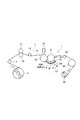
前記特許文献1に記載の装置は、図3に示すごとき構成である。すなわち、微細な凹凸パターンを外周面に備えた転写ロール100に近接してほぼ同一高さ位置に配置したニップロール101によって透明なフィルム102を案内し、前記転写ロール100の下側を通過した前記フィルム102を、前記転写ロール100よりも高い位置に配置したガイドロール103に巻回して送り出す構成である。
The apparatus described in Patent Document 1 has a configuration as shown in FIG. That is, the
そして、前記転写ロール100と前記ニップロール101に巻回した前記フィルム102との間に、タンク104からノズル105を介して紫外線硬化性組成物106を供給している。前記紫外線硬化性組成物106は、前記転写ロール100の外周面とフィルム102との間に挟圧された状態でもって移送されるとき、紫外線発光光源107から紫外線の照射を受けて硬化することにより、前記フィルム102の表面に、前記転写ロール100の外周面に備えた微細な凹凸パターンが転写された凹凸構造体108が形成されるものである。
An ultraviolet
上記構成においては、狭い範囲において紫外線を照射するものであるから、移動している紫外線硬化性組成物106を短時間で確実に硬化するには照射強度を強く(大きく)する必要があり、硬化熱も大きくなり、熱影響を少なくして凹凸構造体108をより高精度に形成するには問題がある。
In the above configuration, since ultraviolet rays are irradiated in a narrow range, it is necessary to increase (increase) the irradiation intensity in order to reliably cure the moving ultraviolet
本発明は前述のごとき問題に鑑みてなされたもので、フィルム表面に微細な凹凸パターンを備えたフィルム構造体の製造方法であって、外周面に微細な凹凸パターンを備えた転写ロールの周面に沿ってフィルムを送り込む際に、上記フィルム表面にUV硬化性樹脂を塗工する工程と、上記UV硬化性樹脂を塗工したフィルムの表面を前記転写ロールに所定の範囲に亘って面接触しかつ密着した状態を保持して移送する工程と、前記転写ロールと前記フィルムとが少なくとも面接触した領域にUV光を照射して前記UV硬化性樹脂を硬化するとき、前記転写ロールの少なくとも周囲に配置した複数のUV光源を複数のグループに区分けしたグループ毎にUV光の照射強度を異にして、或は個々のUV光源におけるUV光の照射強度を異にして、前記UV硬化性樹脂を硬化するための領域へUV光を照射して前記UV硬化性樹脂の硬化を行う工程の各工程を備えていることを特徴とするものである。 The present invention has been made in view of the above-described problems, and is a method for producing a film structure having a fine uneven pattern on the film surface, the peripheral surface of a transfer roll having a fine uneven pattern on the outer peripheral surface. When the film is fed along the surface, the surface of the film coated with the UV curable resin is brought into surface contact with the transfer roll over a predetermined range. And a step of maintaining and transferring the contacted state, and at least a periphery of the transfer roll when the UV curable resin is cured by irradiating UV light to a region where the transfer roll and the film are at least in surface contact with each other. and different from the irradiation intensity of the UV light a plurality of UV light sources disposed in each group was divided into a plurality of groups, or by different in irradiation intensity of UV light in the individual UV light sources, Serial and is characterized in that it comprises the steps to the area for curing the UV curable resin is irradiated with UV light step of performing curing of the UV curable resin.
また、前記フィルム構造体の製造方法において、前記フィルムの移送方向の上流側に位置するUV光源よりも下流側に位置するUV光源におけるUV光の照射強度が次第に大きくなることを特徴とするものである。 Further, in the method for producing a film structure, the irradiation intensity of the UV light in the UV light source positioned downstream is gradually increased from the UV light source positioned upstream in the transport direction of the film. is there.
また、フィルム表面に微細な凹凸パターンを備えたフィルム構造体の製造装置であって、外周面に微細な凹凸パターンを備えた転写ロールと、前記転写ロールの周面に沿ってフィルムを送り込むフィルム送り手段と、前記フィルムの表面へUV硬化性樹脂を塗工するための塗工手段と、前記UV硬化性樹脂を塗工した前記フィルムの表面を前記転写ロールへ押圧するバックアップロールと、前記転写ロールと前記フィルムとが少なくとも面接触した領域へUV光を照射するUV光照射手段とを備え、上記UV光照射手段は、前記フィルムの移送方向及び前記フィルムの幅方向に複数のUV光源が配置してあり、上記複数のUV光源は、前記転写ロールの少なくとも周囲に配置してあることを特徴とするものである。 Moreover, it is a manufacturing apparatus of the film structure provided with the fine uneven pattern on the film surface, and the film feed for feeding the film along the peripheral surface of the transfer roll having the fine uneven pattern on the outer peripheral surface Means, a coating means for applying a UV curable resin to the surface of the film, a backup roll for pressing the surface of the film coated with the UV curable resin against the transfer roll, and the transfer roll And UV light irradiating means for irradiating UV light to an area where at least the film is in surface contact, and the UV light irradiating means includes a plurality of UV light sources arranged in the transport direction of the film and the width direction of the film. The plurality of UV light sources are arranged at least around the transfer roll.
また、前記フィルム構造体の製造装置において、前記複数のUV光源は、複数のグループに区分けしてあり、各グループ毎にUV光の照射強度を制御可能に構成してあることを特徴とするものである。 In the apparatus for manufacturing a film structure, the plurality of UV light sources are divided into a plurality of groups, and the irradiation intensity of the UV light can be controlled for each group. It is.
また、前記フィルム構造体の製造装置において、前記バックアップロールは、当該バックアップロールの長手方向の中央部付近の径よりも両端側が次第に小径となる形状であり、前記バックアップロールが前記フィルムを前記転写ロールへ押圧する部分にUV光を照射するための複数のUV光源を、前記バックアップロールが前記フィルムを押圧する直線部分に沿って配置し、前記バックアップロールの長手方向の中央部に位置するUV光源のUV光の照射強度よりも両側に位置するUV光源のUV光の照射強度を弱くしてあることを特徴とするものである。 In the film structure manufacturing apparatus, the backup roll has a shape in which both end sides gradually become smaller in diameter than the diameter in the vicinity of the central portion in the longitudinal direction of the backup roll, and the backup roll transfers the film to the transfer roll. A plurality of UV light sources for irradiating UV light to the portion to be pressed toward the portion are arranged along a straight portion where the backup roll presses the film, and the UV light source located at the center in the longitudinal direction of the backup roll The present invention is characterized in that the irradiation intensity of the UV light of the UV light source located on both sides is weaker than the irradiation intensity of the UV light.
本発明によれば、長手方向へ移動するフィルムの移動方向及びフィルムの幅方向に複数のUV光源を配置して全体として面的な広がりを有してUV光を照射することができ、かつ面的な広がりの範囲内においてUV光の照射強度を調整できるので、UV硬化性樹脂の硬化熱を抑制することができ、硬化熱の熱影響を小さくしてのより高精度の微細な凹凸パターンの形成を行うことができるものである。 According to the present invention, a plurality of UV light sources can be arranged in the moving direction of the film moving in the longitudinal direction and in the width direction of the film to irradiate the UV light with a planar spread as a whole. The UV light irradiation intensity can be adjusted within the range of the general spread, so that the heat of curing of the UV curable resin can be suppressed, and the fine uneven pattern with higher accuracy can be achieved by reducing the thermal effect of the curing heat. It can be formed.
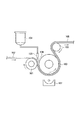
以下、図面を用いて本発明の実施形態に係るフィルム構造体の製造装置について説明する。図1に概念的、概略的に示すように、本発明の実施形態に係るフィルム構造体の製造装置1は、外周面に例えばナノスケールの微細な凹凸パターンを備えた転写ロール3を回転自在に備えており、この転写ロール3の一側方には、前記転写ロール3の周面に沿って透明な樹脂製のフィルム5を送り込むためのフィルム送り手段7を備えている。
Hereinafter, the manufacturing apparatus of the film structure which concerns on embodiment of this invention is demonstrated using drawing. As conceptually and schematically shown in FIG. 1, a film structure manufacturing apparatus 1 according to an embodiment of the present invention is capable of rotating a
上記フィルム送り手段7は、長尺のフィルム5を巻き込んだ送りロール9を備えており、この送りロール9から巻き戻される前記フィルム5を案内するガイドロール11,フィルム5の送り出しを行う一対のピンチロール13,テンションロール15を、フィルム5の送り方向(移送方向)に見て上流側から順に備えている。そして、前記転写ロール3に近接した上流側には、前記フィルム5の表面(上面)にUV硬化性樹脂を塗工するための塗工手段17が配置してある。この塗工手段17は、一般的な塗工装置でよいので、前記塗工手段17についての詳細な説明は省略する。
The film feeding means 7 includes a
さらに、前記転写ロール3に近接した上流側には、UV硬化性樹脂を塗工した前記フィルム5の表面を前記転写ロール3へ押圧するためのバックアップロール19が回転自在に配置してある。このバックアップロール19は、バックアップロール19のほぼ全長に亘って均等に押圧するように、バックアップロール19の軸方向(図1において紙面に垂直な方向で、バックアップロール19の長手方向)の中央部の径よりも、両端側の径が次第に小径になるように形成してあり、その軸心は前記転写ロール3の軸心とほぼ同一高さ位置に設けられている。そして、前記転写ロール3と一体的に回転するように構成してある。
Further, a
前記転写ロール3の下流側には、前記転写ロール3の外周面の下部側の所定範囲に亘って前記フィルム5の面接触を保持するためのガイドロール21が前記転写ロール3の軸心位置より高位置に配置してある。さらに、前記フィルム5を案内するためのガイドロール23が回転自在に配置してあると共に、前記フィルム5を巻き取るための巻取ロール25が回転自在に備えられている。
On the downstream side of the
前記転写ロール3の周面に備えた微細な凹凸パターンを前記UV硬化性樹脂に転写し、このUV硬化性樹脂をUV硬化させるために、前記転写ロール3の下部外周面に面接触したフィルム5の面接触領域に対応してUV照射手段27が配置してある。より詳細には、前記転写ロール3の下方には、前記転写ロール3の軸心を中心とする円弧状の曲面を呈する光源支持部材29が配置してあり、この光源支持部材29にはUV光源31の一例としての複数の紫外線LEDが前記フィルム5の移送方向及びフィルム5の幅方向,換言すれば前記転写ロール3の下側周面に沿う方向及び転写ロール3の軸心に沿う方向に面的な広がりを保持して配置してある。すなわち、複数のUV光源31は、前記転写ロール3の少なくとも下側周囲に配置してある。
A film 5 in surface contact with the lower outer peripheral surface of the
前記複数のUV光源31は、図2に示すように、複数列、複数行に配置してある。すなわち、複数のUV光源31は、フィルム5の移送方向(矢印方向)のA列〜D列に配置してあって、各A〜D列の複数のグループに区分けしてあり、各グループA〜D毎にUV光の照射強度を調節可能に構成してある。上記各グループA〜D毎にUV光の照射強度を調節可能な構成の1例としては、例えば次のごとき構成とすることができる。
As shown in FIG. 2, the plurality of
すなわち、各グループA〜Dに含まれる複数のUV光源31を各グループA〜D毎に直列に接続し、かつ各グループA〜Dと電源33とを接続した接続回路に、電流調整回路(電流調整手段)35を直列に接続した構成とする。この電流調整手段35としては、例えば電流値の異なる複数の定電流ダイオード37A,37Bを並列に接続し、各定電流ダイオード37A,37Bにスイッチング素子39A,39Bをそれぞれ直列に接続した構成とする。そして、前記各スイッチング素子39A,39BのON,OFFを制御するためのスイッチ制御手段41を備えた構成とすることができる。
That is, a plurality of
なお、複数のUV光源31を複数のグループに区分けする構成としては、フィルム5の移送方向の列毎に区分けする他に、フィルム5の幅方向の行毎に区分けすることも可能である。さらには、UV光源31の配置に拘わりなく適数のUV光源31を任意に選択したグループに区分けすることも可能である。すなわち、複数のUV光源31をグループ分けすることは必要に応じて行なえばよいものである。また、各グループにおけるUV光源31の数は必ずしも同一にする必要はなく任意の数とすることができる。
In addition, as a structure which divides the several
上記構成によれば、複数(本例においては2個)のスイッチング素子39A,39Bの適宜一方をON動作すること、又は両スイッチング素子39A,39Bを共にON動作することにより、各グループA〜Dにおける電流値を3種に制御することができるものであり、照射強度を3段階に調整することができる。なお、上記電流調整手段35の構成は一例にすぎないものであり、その他の構成とすることも可能で、UV照射強度を無段階に調整することができるものである。
According to the above configuration, each of the groups A to D can be operated by appropriately turning on one of a plurality (two in this example) of the
さらに、前記転写ロール3に対するバックアップロール19の押圧位置においてUV硬化性樹脂の硬化を図るために、上記押圧位置の中央部(転写ロール3,バックアップロール19の長手方向の中央部)付近をUV照射するためのUV光源43A(図2参照)及び前記押圧位置の両側付近をUV照射するためのUV光源43B,43Cが前記UV光源43Aの側方に配置してある。上記UV光源43A,43B,43Cにおいては、中央部におけるUV光源43AのUV照射強度は両側のUV光源43B,43CのUV照射強度より大きいものであり、両側のUV光源43B,43CのUV照射強度はほぼ等しい照射強度である。なお、前記各UV光源43A,43B,43Cにそれぞれ前述同様の電流調整手段35を接続して備えることにより、各UV光源43A,43B,43CのUV照射強度を個別に制御する構成とすることも可能である。
Further, in order to cure the UV curable resin at the pressing position of the
以上のごとき構成において、送りロール9からフィルム5を巻き戻し、塗工手段17によって前記フィルム5の表面にUV硬化性樹脂を塗工した後、バックアップロール19によってフィルム5の表面を転写ロール3へ押圧し、フィルム5が転写ロール3に面接触し密着した状態を保持しつつ移送し、UV照射手段27によって前記面接触した領域、すなわちUV硬化性樹脂のUV硬化を行うための領域にUV照射を行って前記UV硬化性樹脂のUV硬化を行うことにより、前記転写ロール3の外周面に備えた微細な凹凸パターンがフィルム5へ転写されて、フィルム表面に微細な凹凸パターンを備えたフィルム構造体が製造されることになる。
In the configuration as described above, the film 5 is rewound from the
前述のごとく、バックアップロール19によってフィルム5を転写ロール3へ押圧するとき、バックアップロール19の両端側の径が中央部の径より次第に小径になるように形成してあるので、両端支持のバックアップロール19は全長に亘ってほぼ均等にフィルム5を転写ロール3へ押圧することになる。そして、前記バックアップロール19が転写ロール3へフィルム5を押圧している中央部付近及び両端側は、中央部のUV光源43A及び両端側のUV光源から照射されるUV光によってUV硬化性樹脂は硬化を開始しており、かつ中央部付近のUV硬化が両端側より進行して流動性が低下しているので、両端側への流動及び両端側から外部へ流出する流動が抑制されて、フィルム5の全幅に亘って均等厚に保持される。
As described above, when the film 5 is pressed against the
その後、UV照射手段27に対応した位置においてさらに強力にUV照射を受けることにより、UV硬化性樹脂のUV硬化が進行する。この際、フィルム5の移送方向の上流側に位置するグループAにおけるUV光源31の照射強度よりも下流側に位置するグループB,C,DにおけるUV光源31の照射強度が次第に大きくなるので、UV硬化性樹脂のUV硬化は次第に進行するものであって、UV光源31を1列に配置してUV照射の強度を大きくして上記1列の部分においてUV硬化性樹脂のUV硬化を一挙に行う場合に比較して、硬化熱を抑制することができるものである。したがって、硬化熱による熱影響が少なく、またUV硬化後のUV硬化性樹脂の粗密を生じることなく、より高精度の転写を行うことができるものである。
Thereafter, UV curing of the UV curable resin proceeds by receiving UV irradiation more strongly at a position corresponding to the UV irradiation means 27. At this time, since the irradiation intensity of the
ところで、上記説明においては、グループAにおけるUV光源31よりも下流側のグループB,C,DにおけるUV光源31の照射強度が次第に大きくなる場合について説明したが、UV硬化性樹脂の特性によっては、前述とは逆に、下流側のグループにおけるUV光源31の照射強度を次第に小さく(弱く)することも可能である。さらに、フィルム5の幅方向(転写ロール3の軸方向)の行をグループに区分した場合には、中央部のグループに属するUV光源31の照射強度を大きくして、両側のグループに属するUV光源31の照射強度を次第に弱くすることも可能である。
In the above description, the case where the irradiation intensity of the
また、前記列のグループA,B,C,Dと行のグループを組合わせて、グループA,B,C,D毎の照射強度の調整と行のグループ毎の照射強度を組合わせることも可能である。すなわち、フィルム5の移送方向の上流側又は下流側ほどUV照射強度が大きくなるように調整すると共に、フィルム5の幅方向の中央部から両側方におけるUV光源31の照射強度が次第に小さくなるように、又は次第に大きくなるように調整することも可能である。また、複数のUV光源31をグループ分けすることなく個々の照射強度を調整する構成とすることも可能である。
It is also possible to combine the group A, B, C, D of the column and the group of the row, and to adjust the irradiation intensity for each of the groups A, B, C, D and the irradiation intensity of each group of the row. It is. In other words, the UV irradiation intensity is adjusted to increase toward the upstream side or the downstream side in the transfer direction of the film 5, and the irradiation intensity of the
また、例えば転写ロール3の回転を検出し、凹凸パターンにおいて深い凹部が対応する位置に来たときにUV照射強度を大きく調整するなど、凹凸パターンにおける凹部の深さに対応してUV光の照射強度を調整することも可能である。
Further, for example, the rotation of the
また、複数のUV光源31の配置としては、前述したごとき列,行に限ることなく極座標的に配置することや任意に配置することも可能である。
Further, the arrangement of the plurality of UV
さらに、UV光源としてLEDを使用する場合、照射されるUVの拡散を図るために、前記転写ロール3とUV照射手段27との間に拡散板45を配置することが望ましい。このように、拡散板45を配置することにより、UV光が拡散されて、フィルム5と転写ロール3との接触面に均等的に照射されることになる。
Further, when an LED is used as the UV light source, it is desirable to dispose a
ところで、前述の説明においては、転写ロール3とフィルム5とが接触した状態にある転写ロール3の下側周面へUV光の照射を行う場合について説明した。しかし、UV硬化性樹脂にUV光を照射してUV硬化を行うための領域は、前記転写ロール3の下側周面に限ることなく、例えば転写ロール3からフィルム5が離れた下流側の領域をも含めることが可能である。すなわち、転写ロール3の下流側にもUV照射手段を配置し、この下流側のUV照射手段によって、転写ロール3から離れた後のフィルム5にUV光の照射を行うものである。
By the way, in the above description, the case where UV light is irradiated to the lower peripheral surface of the
上記のごとき構成とすることにより、すなわち、転写ロール3の周囲のみならず、その近傍にも複数のUV光源を配置して、フィルム5に対してUV光の照射を行うこととなり、UV硬化性樹脂をより完全に硬化することができるものである。なお、前記転写ロール3の下流側においてUV光の照射を行う場合には、フィルム5の裏面側,表面側の一方又は両方からUV光を照射することができるものである。
By adopting the above-described configuration, that is, a plurality of UV light sources are arranged not only around the
以上のごとき説明より理解されるように、転写ロール3の周面に備えられた微細な凹凸パターンをフィルム5に転写するとき、UV硬化性樹脂を、フィルム5と転写ロール3との接触面内において徐々にUV硬化することが可能であり、硬化熱を抑制しつつ硬化することができるものである。したがって硬化熱による熱影響を抑制して転写することができ、UV硬化後に部分的に粗密を生じることなく、より高精度の転写を行うことができるものである。
As will be understood from the above description, when the fine uneven pattern provided on the peripheral surface of the
3 転写ロール
5 フィルム
7 フィルム送り手段
9 送りロール
17 塗工手段
19 バックアップロール
21 ガイドロール
25 巻取ロール
27 UV照射手段
29 光源支持部材
31,43A,43B,43C UV光源
35 電流調整手段
37A,37B 定電流ダイオード
39A,39B スイッチング素子
41 スイッチ制御手段
45 拡散板
DESCRIPTION OF
Claims (5)
(a)外周面に微細な凹凸パターンを備えた転写ロールの周面に沿ってフィルムを送り込む際に、上記フィルム表面にUV硬化性樹脂を塗工する工程、
(b)上記UV硬化性樹脂を塗工したフィルムの表面を前記転写ロールに所定の範囲に亘って面接触しかつ密着した状態を保持して移送する工程、
(c)前記転写ロールと前記フィルムとが少なくとも面接触した領域にUV光を照射して前記UV硬化性樹脂を硬化するとき、前記転写ロールの少なくとも周囲に配置した複数のUV光源を複数のグループに区分けしたグループ毎にUV光の照射強度を異にして、或は個々のUV光源におけるUV光の照射強度を異にして、前記UV硬化性樹脂を硬化するための領域へUV光を照射して前記UV硬化性樹脂の硬化を行う工程、
の各工程を備えていることを特徴とするフィルム構造体の製造方法。 A method for producing a film structure having a fine uneven pattern on the film surface,
(A) a step of applying a UV curable resin to the film surface when feeding the film along the peripheral surface of a transfer roll having a fine uneven pattern on the outer peripheral surface;
(B) a step of transferring the surface of the film coated with the UV curable resin while maintaining a state of being in surface contact with and in close contact with the transfer roll over a predetermined range;
When (c) the transfer roll and said film to cure the UV curable resin is irradiated with UV light in a region at least surface contact, a plurality of a plurality of UV light sources disposed at least around the transfer roll Irradiate the UV light to the area for curing the UV curable resin with different UV light irradiation intensity for each group divided into different groups, or with different UV light irradiation intensity in each UV light source. And curing the UV curable resin,
A method for producing a film structure comprising the steps of:
上記UV光照射手段は、前記フィルムの移送方向及び前記フィルムの幅方向に複数のUV光源が配置してあり、上記複数のUV光源は、前記転写ロールの少なくとも周囲に配置してあることを特徴とするフィルム構造体の製造装置。 An apparatus for producing a film structure having a fine concavo-convex pattern on a film surface, a transfer roll having a fine concavo-convex pattern on an outer peripheral surface, and a film feeding means for feeding the film along the peripheral surface of the transfer roll; , A coating means for applying a UV curable resin to the surface of the film, a backup roll for pressing the surface of the film coated with the UV curable resin against the transfer roll, the transfer roll, and the UV light irradiating means for irradiating UV light to a region where the film is at least in surface contact,
The UV light irradiation means includes a plurality of UV light sources arranged in the film transfer direction and the film width direction, and the plurality of UV light sources are arranged at least around the transfer roll. An apparatus for manufacturing a film structure.
Priority Applications (1)
| Application Number | Priority Date | Filing Date | Title |
|---|---|---|---|
| JP2007019415A JP4976868B2 (en) | 2007-01-30 | 2007-01-30 | Film structure manufacturing method and apparatus |
Applications Claiming Priority (1)
| Application Number | Priority Date | Filing Date | Title |
|---|---|---|---|
| JP2007019415A JP4976868B2 (en) | 2007-01-30 | 2007-01-30 | Film structure manufacturing method and apparatus |
Publications (2)
| Publication Number | Publication Date |
|---|---|
| JP2008183811A JP2008183811A (en) | 2008-08-14 |
| JP4976868B2 true JP4976868B2 (en) | 2012-07-18 |
Family
ID=39727148
Family Applications (1)
| Application Number | Title | Priority Date | Filing Date |
|---|---|---|---|
| JP2007019415A Active JP4976868B2 (en) | 2007-01-30 | 2007-01-30 | Film structure manufacturing method and apparatus |
Country Status (1)
| Country | Link |
|---|---|
| JP (1) | JP4976868B2 (en) |
Cited By (1)
| Publication number | Priority date | Publication date | Assignee | Title |
|---|---|---|---|---|
| US11518081B2 (en) | 2019-03-11 | 2022-12-06 | Panasonic Intellectual Property Management Co., Ltd. | Method and apparatus for manufacturing film structure |
Families Citing this family (1)
| Publication number | Priority date | Publication date | Assignee | Title |
|---|---|---|---|---|
| TW201425178A (en) * | 2012-12-26 | 2014-07-01 | Hon Hai Prec Ind Co Ltd | Device for manufacturing phosphor powder film and method for manufacturing same by using the device |
Family Cites Families (4)
| Publication number | Priority date | Publication date | Assignee | Title |
|---|---|---|---|---|
| JPH0336022A (en) * | 1989-07-03 | 1991-02-15 | Fuji Photo Film Co Ltd | Manufacture of optical disc |
| JPH11179277A (en) * | 1997-12-24 | 1999-07-06 | Mitsubishi Heavy Ind Ltd | Method and apparatus for manufacturing barrier rib |
| JP2000210618A (en) * | 2000-01-01 | 2000-08-02 | Dainippon Printing Co Ltd | Manufacturing method of light diffusion sheet |
| JP4329122B2 (en) * | 2003-11-28 | 2009-09-09 | 富士フイルム株式会社 | Method and apparatus for manufacturing uneven sheet |
-
2007
- 2007-01-30 JP JP2007019415A patent/JP4976868B2/en active Active
Cited By (1)
| Publication number | Priority date | Publication date | Assignee | Title |
|---|---|---|---|---|
| US11518081B2 (en) | 2019-03-11 | 2022-12-06 | Panasonic Intellectual Property Management Co., Ltd. | Method and apparatus for manufacturing film structure |
Also Published As
| Publication number | Publication date |
|---|---|
| JP2008183811A (en) | 2008-08-14 |
Similar Documents
| Publication | Publication Date | Title |
|---|---|---|
| JP5886166B2 (en) | Pretreatment method, apparatus and system for contact flattening radiation curable gel ink | |
| JP6203628B2 (en) | Fine pattern forming method | |
| KR102328775B1 (en) | Apparatus for imprinting individual substrates with flexible stamps | |
| JP6032492B2 (en) | Fine pattern forming method and fine pattern forming apparatus | |
| JP5593190B2 (en) | Mold peeling device | |
| TWI698354B (en) | Optical fiber ribbon manufacturing device and optical fiber ribbon manufacturing method | |
| CN107921700B (en) | Manufacturing method of laminated film and manufacturing apparatus of laminated film | |
| JP4976868B2 (en) | Film structure manufacturing method and apparatus | |
| KR20160106485A (en) | Imprinting device | |
| US20150085040A1 (en) | Led ink curing apparatus | |
| JP4329122B2 (en) | Method and apparatus for manufacturing uneven sheet | |
| JP6596822B2 (en) | Light irradiator and printing apparatus | |
| JP7221642B2 (en) | Transfer device | |
| TWI552861B (en) | Apparatus and methods for fabricating a light guide film | |
| JP4778788B2 (en) | Fine pattern sheet creating apparatus and fine pattern sheet creating method | |
| TWM563352U (en) | Apparatus for imprinting | |
| JPWO2013031196A1 (en) | Method for producing tape-shaped pattern medium | |
| JP2005138296A (en) | Method and apparatus for manufacturing embossed sheet | |
| JP5479259B2 (en) | Coating apparatus and optical film manufacturing method | |
| JP2022512224A5 (en) | ||
| KR102783259B1 (en) | Transport roller and semiconductor component manufacturing apparatus having the same | |
| JP4804915B2 (en) | Sheet release device and sheet release method | |
| KR20150046644A (en) | Resin dispenser for nano-imprint | |
| JP7286561B2 (en) | PATTERN FORMING DEVICE AND PATTERN FORMING METHOD | |
| KR102495255B1 (en) | Apparatus manufacturing photonic crystal film and method thereof |
Legal Events
| Date | Code | Title | Description |
|---|---|---|---|
| A621 | Written request for application examination |
Free format text: JAPANESE INTERMEDIATE CODE: A621 Effective date: 20090914 |
|
| A977 | Report on retrieval |
Free format text: JAPANESE INTERMEDIATE CODE: A971007 Effective date: 20120123 |
|
| A131 | Notification of reasons for refusal |
Free format text: JAPANESE INTERMEDIATE CODE: A131 Effective date: 20120131 |
|
| A521 | Written amendment |
Free format text: JAPANESE INTERMEDIATE CODE: A523 Effective date: 20120316 |
|
| TRDD | Decision of grant or rejection written | ||
| A01 | Written decision to grant a patent or to grant a registration (utility model) |
Free format text: JAPANESE INTERMEDIATE CODE: A01 Effective date: 20120410 |
|
| A01 | Written decision to grant a patent or to grant a registration (utility model) |
Free format text: JAPANESE INTERMEDIATE CODE: A01 |
|
| A61 | First payment of annual fees (during grant procedure) |
Free format text: JAPANESE INTERMEDIATE CODE: A61 Effective date: 20120413 |
|
| R150 | Certificate of patent or registration of utility model |
Ref document number: 4976868 Country of ref document: JP Free format text: JAPANESE INTERMEDIATE CODE: R150 Free format text: JAPANESE INTERMEDIATE CODE: R150 |
|
| FPAY | Renewal fee payment (event date is renewal date of database) |
Free format text: PAYMENT UNTIL: 20150420 Year of fee payment: 3 |
|
| S533 | Written request for registration of change of name |
Free format text: JAPANESE INTERMEDIATE CODE: R313533 |
|
| R350 | Written notification of registration of transfer |
Free format text: JAPANESE INTERMEDIATE CODE: R350 |