JP4968979B2 - Small position sensor - Google Patents
Small position sensor Download PDFInfo
- Publication number
- JP4968979B2 JP4968979B2 JP26568299A JP26568299A JP4968979B2 JP 4968979 B2 JP4968979 B2 JP 4968979B2 JP 26568299 A JP26568299 A JP 26568299A JP 26568299 A JP26568299 A JP 26568299A JP 4968979 B2 JP4968979 B2 JP 4968979B2
- Authority
- JP
- Japan
- Prior art keywords
- coil
- coils
- assembly
- photoengraving
- axes
- Prior art date
- Legal status (The legal status is an assumption and is not a legal conclusion. Google has not performed a legal analysis and makes no representation as to the accuracy of the status listed.)
- Expired - Lifetime
Links
Images


Classifications
-
- A—HUMAN NECESSITIES
- A61—MEDICAL OR VETERINARY SCIENCE; HYGIENE
- A61B—DIAGNOSIS; SURGERY; IDENTIFICATION
- A61B5/00—Measuring for diagnostic purposes; Identification of persons
- A61B5/06—Devices, other than using radiation, for detecting or locating foreign bodies ; determining position of probes within or on the body of the patient
- A61B5/065—Determining position of the probe employing exclusively positioning means located on or in the probe, e.g. using position sensors arranged on the probe
-
- A—HUMAN NECESSITIES
- A61—MEDICAL OR VETERINARY SCIENCE; HYGIENE
- A61B—DIAGNOSIS; SURGERY; IDENTIFICATION
- A61B5/00—Measuring for diagnostic purposes; Identification of persons
- A61B5/06—Devices, other than using radiation, for detecting or locating foreign bodies ; determining position of probes within or on the body of the patient
- A61B5/061—Determining position of a probe within the body employing means separate from the probe, e.g. sensing internal probe position employing impedance electrodes on the surface of the body
- A61B5/062—Determining position of a probe within the body employing means separate from the probe, e.g. sensing internal probe position employing impedance electrodes on the surface of the body using magnetic field
-
- A—HUMAN NECESSITIES
- A61—MEDICAL OR VETERINARY SCIENCE; HYGIENE
- A61B—DIAGNOSIS; SURGERY; IDENTIFICATION
- A61B5/00—Measuring for diagnostic purposes; Identification of persons
- A61B5/68—Arrangements of detecting, measuring or recording means, e.g. sensors, in relation to patient
- A61B5/6846—Arrangements of detecting, measuring or recording means, e.g. sensors, in relation to patient specially adapted to be brought in contact with an internal body part, i.e. invasive
- A61B5/6847—Arrangements of detecting, measuring or recording means, e.g. sensors, in relation to patient specially adapted to be brought in contact with an internal body part, i.e. invasive mounted on an invasive device
- A61B5/6852—Catheters
-
- G—PHYSICS
- G01—MEASURING; TESTING
- G01B—MEASURING LENGTH, THICKNESS OR SIMILAR LINEAR DIMENSIONS; MEASURING ANGLES; MEASURING AREAS; MEASURING IRREGULARITIES OF SURFACES OR CONTOURS
- G01B7/00—Measuring arrangements characterised by the use of electric or magnetic techniques
- G01B7/003—Measuring arrangements characterised by the use of electric or magnetic techniques for measuring position, not involving coordinate determination
-
- G—PHYSICS
- G01—MEASURING; TESTING
- G01B—MEASURING LENGTH, THICKNESS OR SIMILAR LINEAR DIMENSIONS; MEASURING ANGLES; MEASURING AREAS; MEASURING IRREGULARITIES OF SURFACES OR CONTOURS
- G01B7/00—Measuring arrangements characterised by the use of electric or magnetic techniques
- G01B7/004—Measuring arrangements characterised by the use of electric or magnetic techniques for measuring coordinates of points
-
- G—PHYSICS
- G01—MEASURING; TESTING
- G01B—MEASURING LENGTH, THICKNESS OR SIMILAR LINEAR DIMENSIONS; MEASURING ANGLES; MEASURING AREAS; MEASURING IRREGULARITIES OF SURFACES OR CONTOURS
- G01B7/00—Measuring arrangements characterised by the use of electric or magnetic techniques
- G01B7/30—Measuring arrangements characterised by the use of electric or magnetic techniques for measuring angles or tapers; for testing the alignment of axes
-
- G—PHYSICS
- G01—MEASURING; TESTING
- G01D—MEASURING NOT SPECIALLY ADAPTED FOR A SPECIFIC VARIABLE; ARRANGEMENTS FOR MEASURING TWO OR MORE VARIABLES NOT COVERED IN A SINGLE OTHER SUBCLASS; TARIFF METERING APPARATUS; MEASURING OR TESTING NOT OTHERWISE PROVIDED FOR
- G01D5/00—Mechanical means for transferring the output of a sensing member; Means for converting the output of a sensing member to another variable where the form or nature of the sensing member does not constrain the means for converting; Transducers not specially adapted for a specific variable
- G01D5/12—Mechanical means for transferring the output of a sensing member; Means for converting the output of a sensing member to another variable where the form or nature of the sensing member does not constrain the means for converting; Transducers not specially adapted for a specific variable using electric or magnetic means
- G01D5/14—Mechanical means for transferring the output of a sensing member; Means for converting the output of a sensing member to another variable where the form or nature of the sensing member does not constrain the means for converting; Transducers not specially adapted for a specific variable using electric or magnetic means influencing the magnitude of a current or voltage
- G01D5/20—Mechanical means for transferring the output of a sensing member; Means for converting the output of a sensing member to another variable where the form or nature of the sensing member does not constrain the means for converting; Transducers not specially adapted for a specific variable using electric or magnetic means influencing the magnitude of a current or voltage by varying inductance, e.g. by a movable armature
- G01D5/204—Mechanical means for transferring the output of a sensing member; Means for converting the output of a sensing member to another variable where the form or nature of the sensing member does not constrain the means for converting; Transducers not specially adapted for a specific variable using electric or magnetic means influencing the magnitude of a current or voltage by varying inductance, e.g. by a movable armature by influencing the mutual induction between two or more coils
- G01D5/2073—Mechanical means for transferring the output of a sensing member; Means for converting the output of a sensing member to another variable where the form or nature of the sensing member does not constrain the means for converting; Transducers not specially adapted for a specific variable using electric or magnetic means influencing the magnitude of a current or voltage by varying inductance, e.g. by a movable armature by influencing the mutual induction between two or more coils by movement of a single coil with respect to two or more coils
-
- G—PHYSICS
- G01—MEASURING; TESTING
- G01D—MEASURING NOT SPECIALLY ADAPTED FOR A SPECIFIC VARIABLE; ARRANGEMENTS FOR MEASURING TWO OR MORE VARIABLES NOT COVERED IN A SINGLE OTHER SUBCLASS; TARIFF METERING APPARATUS; MEASURING OR TESTING NOT OTHERWISE PROVIDED FOR
- G01D5/00—Mechanical means for transferring the output of a sensing member; Means for converting the output of a sensing member to another variable where the form or nature of the sensing member does not constrain the means for converting; Transducers not specially adapted for a specific variable
- G01D5/12—Mechanical means for transferring the output of a sensing member; Means for converting the output of a sensing member to another variable where the form or nature of the sensing member does not constrain the means for converting; Transducers not specially adapted for a specific variable using electric or magnetic means
- G01D5/14—Mechanical means for transferring the output of a sensing member; Means for converting the output of a sensing member to another variable where the form or nature of the sensing member does not constrain the means for converting; Transducers not specially adapted for a specific variable using electric or magnetic means influencing the magnitude of a current or voltage
- G01D5/20—Mechanical means for transferring the output of a sensing member; Means for converting the output of a sensing member to another variable where the form or nature of the sensing member does not constrain the means for converting; Transducers not specially adapted for a specific variable using electric or magnetic means influencing the magnitude of a current or voltage by varying inductance, e.g. by a movable armature
- G01D5/204—Mechanical means for transferring the output of a sensing member; Means for converting the output of a sensing member to another variable where the form or nature of the sensing member does not constrain the means for converting; Transducers not specially adapted for a specific variable using electric or magnetic means influencing the magnitude of a current or voltage by varying inductance, e.g. by a movable armature by influencing the mutual induction between two or more coils
- G01D5/2086—Mechanical means for transferring the output of a sensing member; Means for converting the output of a sensing member to another variable where the form or nature of the sensing member does not constrain the means for converting; Transducers not specially adapted for a specific variable using electric or magnetic means influencing the magnitude of a current or voltage by varying inductance, e.g. by a movable armature by influencing the mutual induction between two or more coils by movement of two or more coils with respect to two or more other coils
-
- H—ELECTRICITY
- H01—ELECTRIC ELEMENTS
- H01Q—ANTENNAS, i.e. RADIO AERIALS
- H01Q7/00—Loop antennas with a substantially uniform current distribution around the loop and having a directional radiation pattern in a plane perpendicular to the plane of the loop
- H01Q7/06—Loop antennas with a substantially uniform current distribution around the loop and having a directional radiation pattern in a plane perpendicular to the plane of the loop with core of ferromagnetic material
- H01Q7/08—Ferrite rod or like elongated core
Description
【0001】
【産業上の利用分野】
本発明は、一般に対象物追跡システムに関し、特に医用プローブの位置及び方向を追跡する非接触式の電磁的な方法及び装置に関する。
【0002】
本願は、米国同時係属暫定出願60/061269号の非暫定特許出願である(弁理士事件整理番号 BIO 0025US)。
【0003】
【従来技術及びその課題】
多くの医療処置において、内視鏡及びカテーテルのようなプローブが患者の体内に挿入される。かかるプローブは、組織標本の切除及び採取のような不可逆性外科行為を含んだ非常に多くの処置に対して使用される。このため、患者の体内におけるプローブの位置及び方向についての正確な情報を有することが必要である。
【0004】
電磁式位置判定システムは、体内物体の位置及び方向の正確な情報を受けこれら物体の正確な追跡を許す簡便な方法を提供する。かかるシステムは、例えば米国特許5558091号、5391199号、及び5443489号、並びに国際特許出願WO94/04938号及びWO96/05768号に説明され、これらの開示は参考文献としてここに取り入れられる。これらのシステムは、ホール効果器具、プローブに担持されたコイル又はアンテナのような1個又は複数個のフィールドセンサーを使用してプローブの座標を判定する。変換器は、プローブの末端又はその付近に、及び/又はプローブの長さに沿って置かれることが典型的である。従って、変換器は、プローブの操作性に干渉することなく、或いはその寸法を不当に大きくすることなくプローブ内に適合するようにできるだけ小さく作られることが好ましい。
【0005】
米国特許5558091号は、相互に直交する3個の薄いガルバノ磁気フィルムを有する直方体のホール効果センサー組立体を説明する。このセンサー組立体は、好ましくは寸法が約3×0.75×0.75mmのものである。5558091号特許は、更に、半導体チップ形式の3個のフィールド検知素子を有する別のホール効果センサー組立体を説明する。各チップは、1個又は複数個の電磁抵抗材料の長いバーを持つ。各チップは、このバーの方向の電磁場の成分に対して敏感である。この組立体は、好ましくは、直径が0.8mm又はそれ以下である。しかし、かかるチップは、非線形、飽和効果、ヒステリシス及び温度ドリフトを受ける。
【0006】
このため、大多数の磁気式の位置判定システムは、巻回数の大きい導電体ワイヤの小型コイルで形成されたセンサーを使用する。かかるコイルは、例えばPCT文書PCT/GB93/01736号、WO94/04938号、及びWO96/05768号、及び上述の米国特許5391199号、及び本願の譲受人に譲渡されたPCT文書PCT/IL97/00009号において説明される。これらの文書の全ては参考文献としてここに組み入れられる。センサーコイルの性能は、コイルの巻回数とコイルの断面積との積の関数であるそのインダクタンスに依存する。このため、外科用プローブ内で使用する小型コイルの計画に当たっては、例えば、コイルの寸法と性能との間の妥協を図ることが一般に必要である。かかるコイルは、典型的に、0.6×0.6×0.6mm、より一般的には0.8×0.8×0.8mmの最小寸法を持つ。同じ形式で更に小さいコイルは、容認できる性能を提供せず、かつ製造が困難でもある。
【0007】
併進方向及び回転方向の両座標を判定するために、上述のPCT文書WO96/05768号に説明されたようなある種の位置判定システムは、それぞれ相互に1次独立性でありかつ好ましくは互いに直交するそれぞれの軸線を有する3個のセンサーコイルを使用する。好ましくは、これら3個のコイルは、センサー組立体を形成するように一緒に包装され、この組立体が、6次元の位置及び方向座標の読みを提供するように使用される。1個の包装内に3個のコイルを有するこの組立体の使用により、カテーテルへのコイルの挿入及び/又は取付けが容易になる。また、この組立体は、コイル相互間の正確な位置決めを提供し、コイルを使用している位置判定システムの較正を単純化する。一般に、コイルは、周囲からコイルを保護する円筒状のケース内に囲まれる。
【0008】
PCT/WO96/05768号のシステムにおいては、この組立体は、典型的に、長さが約6mm、直径が約1.3mmである。6次元の全てにおいて正確な位置の感知を得るためには、コイルの軸線が一般に相互に直交することが要求されるので、組立体の直径をより小さく作ることは不可能である。
【0009】
このコイル組立体は大多数の医用プローブ内に適合するが、ある場合には、性能が同等でより小さい幅のコイルが望まれる。例えば、本願の譲受人に譲渡されかつ参考文献としてここに取り入れられたPCT特願PCT/IL97/00061号は、コイルを内視鏡内の金属製器械から距離を空けることにより、小型位置検知コイルを有する内視鏡の位置判定の精度を高める方法を説明する。コイル組立体を更に小さい幅で作ることができれば、小型コイルと金属製器械との間の距離を更に空けることができ、従ってこの位置判定システムにより更に良好な精度が達成される。
【0010】
コイル組立体の幅を小さくすることにより、位置判定システムを、一般に優れた操作性を有しかつ遠い場所に容易に接近できる狭いプローブで使うことができる。或いは、コイル組立体の幅を減らすことにより、この組立体は、プローブの断面積のより小さい部分を占め、機能装置用の空間及び/又はプローブに沿った作業用通路をより広く残すことができる。
【0011】
写真製版又は超LSI技法で作られるコイルが、本技術においてよく知られる。以下の説明及び実施態様においては、これらコイルは写真製版コイルと呼ばれる。写真製版コイルは、一般に、プラスチック、セラミック又は半導体材料の基板上に印刷された渦巻状の導体の形に作られる。かかるコイルは、通常は、現在利用可能な構成手法を使った4個までの重なった渦巻層よりなる。
【0012】
写真製版コイル又はアンテナは、本技術において知られるような非接触式のスマートカード(smart card)にも普通に使用される。これらのカードは、カードに埋設された写真製版のコイル又はアンテナにより読取り器回路と誘導的に通信しかつ電力を受ける。スマートカードは厚さが0.8mm以下に限定されるので、一般にただ1個のコイルを備え、その軸線はカードの面に対して垂直であることを必要とする。読取り器と通信するために、スマートカードは、適正な接続を達成するために、コイル軸線が読取り器の作る磁場と揃うように適正に向けられることが必要である。
【0013】
【課題を解決するための手段】
厚さは薄いが感度及び/又はQ因子の大きいセンサーコイルを提供することが本発明のある態様の目的である。
【0014】
狭くて長い形状を有する3個の直交するコイルを有するコイル組立体を提供することが本発明のある態様の別の目的である。
【0015】
本発明の好ましい実施例においては、コイル組立体は3個のコイルを備え、その少なくも1個、好ましくは2個が写真製版コイルよりなる。コイルは、相互に1次独立性であり、好ましくは、軸線が相互に実質的に直交する。これら写真製版コイルに使用により、以下説明されるように直径、幅及び/又は奥行きのより小さいコイル組立体を形成できる。
【0016】
本発明のある好ましい実施例においては、コイルの2個が長くて狭い写真製版コイルよりなる。コイルの長さが幅の狭さを補償し、このため、コイルは、位置判定システムの位置センサーとして使用するに満足なインダクタンスを与えるに十分な大きい面積を囲む。好ましくは、コイルの幅は0.8mm以下、最も好ましくは0.6mm以下である。コイルの厚さは、好ましくは写真製版工程によってのみ限定され、そして一般に約0.3mmである。本発明の好ましい実施例においては、写真製版コイルは可撓性基板上に作られ、このため、組立体は組立体を支持しているカテーテルの柔軟性を制限しない。
【0017】
本発明の好ましい実施例においては、組立体は2個の長くて狭い写真製版コイルを備え、これらはその長辺が互いに隣接しかつ互いに実質的に90゜にあるように配列される。写真製版コイルは長手方向軸線を有する長くて狭い箱形を定め、そしてこの長手方向軸線に対して、2個の写真製版コイルのコイル軸線は実質的に直角である。
【0018】
好ましくは、写真製版コイルの基板は、基板の斜めの切断部において互いに隣接するように約45゜の角度で斜めに切断される。この連結が空間を節約し、組立体の占める空間を最小にする。
【0019】
好ましくは小型の巻線コイルである第3のコイルが、そのコイル軸線を長手方向軸線に沿って位置決めされる。好ましくは、第3のコイルは、組立体の幅と奥行きとを実質的に最小にするように箱形の外側にありかつ隣接する。或いは、ワイヤーコイルの直径が写真製版コイルの幅よりも小さく、そしてワイヤーコイルは写真製版コイルにより定められた箱形内に置かれる。従って、コイル組立体は、狭い幅と奥行き、好ましくは0.8mm以下、最も好ましくは約0.6mm以下を有し、このため、組立体を囲んでいる円筒体の直径は約0.9mmより大きくはない。従って、組立体の断面積は、好ましくは1mm2より小さく、より好ましくは0.8mm2より小さく、そして最も好ましくは0.65mm2より小さい。
【0020】
好ましくは、2個の写真製版コイルにより形成された角度内に、長い楕円体状のフェライトコアが収容される。好ましくは、ワイヤーコイルも、コア、最も好ましくは長い楕円体状のコアのまわりに巻かれる。フェライトコアは、組立体のインダクタンス、従ってコイル組立体の感度を大きくする。好ましくは、組立体は、コイルを周囲から保護する円筒状のケース内に囲まれる。
【0021】
本発明の別の好ましい実施例においては、第3のコイルを形成するために、複数の小さい写真製版コイルが使用される。この小さいコイルは、上述のようなコイルにより定められた箱形内で、互いに平行でかつ第1の2個のコイルと直角に置かれる。小さいコイルは、箱形又は箱形を囲んでいる円筒から突き出さないように、約0.4mmの幅を有する長方形であることが好ましい。或いは、複数の写真製版コイルは、第1の2個のコイルの箱形の外であるが、その長手方向軸線に沿って置かれる。
【0022】
本発明のある好ましい実施例においては、コイル組立体は、それぞれの軸線が互いに1次独立性である3個の写真製版コイルを備える。
【0023】
本発明のある好ましい実施例においては、上述のような1個又は複数個の写真製版コイル組立体が医用プローブ内に置かれ、プローブの座標、好ましくは6次元の位置及び方向の座標の判定を許す。これらの組立体においては、各コイルは好ましくは個別のワイヤー接続を持ち、このため、各コイルにおける外部の電磁場の感知された効果が独立して判定される。位置判定システムは、例えば上述の特許出版物WO96/05768号において説明されたように、3個のコイルの全ての感知された効果に基づいて組立体の位置及び方向を判定する。
【0024】
写真製版コイルを有する組立体の使用により、コイルを囲む円筒体の直径をかなり小さくすることができる。この減少した直径のため、組立体をプローブ内に容易に取り付け又は埋設することができる。より小さい組立体はより小さいプローブの使用を可能とし、及び/又はプローブ内の作動用通路及び機能的な装置と組立体との干渉を減らす。また、コイルの小さい幅と厚さとは、プローブ内における金属装置とコイルとの間のより大きな分離を許し、これにより位置判定システムの作動に対する干渉を最小にする。
【0025】
本発明の別の好ましい実施例においては、電力及び/又は情報を誘導伝達するために写真製版コイル組立体が使用される。これら好ましい実施例では、組立体内の3個のコイルが、直列又は並列に一緒に接続されることが好ましい。かかる誘導伝達は、例えば上述のようにスマートカードで使用される。写真製版コイル組立体の狭い幅が、一般に厚さが0.8mmより薄いことを要するスマートカードにおける使用に対して、これを特に適したものとする。このコイル組立体の使用が、スマートカードと読取り器との間の結合を、スマートカードと読取り器との間の角度に対して実質的に感じないようにする。これは、コイル組立体の軸線が相互に1次独立性であるためである。
【0026】
同様に、かかる写真製版コイル組立体は、例えば、1997年9月15日付けPCT特許出願「学習及び試験機能による位置の確定」に説明されたような体内の管の位置の確定装置に使用することができる。この出願は、米国特許出願09/079338号(出願人、事件整理番号BIO 0050.1 US)として出願され、本発明の譲受人に譲渡され、かつ参考文献としてここに取り入れられる。
【0027】
複数のコイルを有し磁気波を送信し又は受信するための小型コイル組立体であって、各コイルがそれぞれ軸線を有し、少なくも2個の軸線が相互に1次独立性であるように、また複数のコイルの全てが実質的に1.0mm2以下、好ましくは実質的に0.8mm2以下、そして最も好ましくは実質的に0.65mm2以下の断面積を有する体積内に収容されるように組み立てられたコイル組立体が提供される。
【0028】
好ましくは、少なくも2個のコイルが写真製版コイルを有する。
【0029】
更に、本発明の好ましい実施例により、互いに1次独立性である軸線を有する2個の写真製版コイルを有し磁気波を送信及び受信するための小型コイル組立体が提供される。
【0030】
写真製版コイルは、好ましくは0.8mmより小さい幅、より好ましくは0.65mmより小さい幅を持つ。
【0031】
2個の写真製版コイルの軸線が実質的に直交することが好ましい。
【0032】
本発明の好ましい実施例においては、組立体は第3のコイルを有し、第3のコイルの軸線及び2個の写真製版コイルの軸線は、相互に1次独立性である。好ましくは、第3のコイルの軸線は、2個の写真製版コイルの軸線に対して実質的に直角である。
【0033】
好ましい実施例においては、第3のコイルは巻線コイルであり、一方、別の好ましい実施例においては、第3のコイルは互いに接続された複数の写真製版回路を持つ。
【0034】
好ましくは、2個の写真製版コイルは、長辺と短辺とを有する長い長方形基板を有し、2個の写真製版コイルは、2個のコイルの長辺が互いに隣接するように整列される。好ましくは、2個の写真製版コイルの基板は互いに実質的に直角に整列される。
【0035】
好ましくは、組立体は、直径が1.1mmより小さい、より好ましくは0.9mmより小さい円筒状体積により囲まれる。
【0036】
好ましい実施例においては、組立体は、コイルのインダクタンスを強化するために強磁性体、好ましくは長い楕円体状のフェライトを備える。好ましくは、フェライトは、組立体の実質的に全てのコイルの共通コアとして作用する。
【0037】
好ましくは、位置判定システムは、コイルの座標を判定するために、電磁場に応答してコイルにより作られた信号を受信し、この信号を解析する。好ましくは、プローブの座標、好ましくは6次元の位置及び方法の座標を見いだすために、侵襲性医用プローブ内にコイルが挿入される。
【0038】
本発明の好ましい実施例により、
写真製版コイル組立体を対象物に取り付け、そして
その座標を判定するために組立体からの信号を受信する
ことを含んだ対象物の位置の判定方法も提供される。
【0039】
好ましくは、組立体の取付けは、写真製版コイルを対象物内に埋設することを含む。
【0040】
更に好ましくは、コイル組立体の取付けは、2個のコイルの軸線が互いに1次独立性であるように、また実質的に1mm2より小さい断面積を有する体積を定めるように、それぞれ軸線を有する2個の写真製版コイルを対象物に固定することを含む。
【0041】
本発明の好ましい実施例により、物体のボデー内で位置が追跡されるプローブであって、
挿入管、及び
挿入管に取り付けられた写真製版コイル組立体
を備えたプローブが提供される。
【0042】
好ましくは、組立体は、断面積が実質的に1.0mm2より小さい体積内に収容される。
【0043】
更に好ましくは、写真製版コイル組立体は、少なくも2個の写真製版コイル及び好ましくは巻線コイルを有し、コイルはそれぞれ軸線を有し、これら軸線は互いに1次独立性であり、かつ最も好ましくは互いに実質的に直交する。
【0044】
本発明の好ましい実施例においては、位置判定システムは、プローブの座標を判定するために、コイルから信号を受信し、そしてこの信号を解析する。
【0045】
本発明は、その好ましい実施例の以下の詳細な説明、及び図面より完全に理解されるであろう。
【0046】
【実施例】
図1及び2は、本発明の好ましい実施例により、写真製版方法を使用して作られたセンサーコイル10を示す。図1は、コイル10の図式的な図を示し、図2は、複数の、通常は4個の層18を有するコイル10の分解図を示す。層の数は、特に現在の写真製版技術の限界により限定される。各層18は、電気絶縁材料の基板14上に堆積された導電性の渦巻12を持つ。渦巻12の端部に置かれた外部ポート61が、本技術において公知のようにコイル10への電気的アクセスを許す。ポート16に接続されたワイヤー26が、コイル10を位置判定システムに、或いは(図示されない)送信器に結合する。この送信器は、位置判定システムへの信号の無線送信を提供する。
【0047】
基板14は、好ましくは、長くて狭い長方形の平らなピースよりなる。好ましくは、基板14は本技術において知られるように厚さが約0.3mmである。基板14の幅(w)は、約0.4から0.7mmの間、好ましくは0.6mmである。好ましくは、基板14の長さ(L1)は約4から5mmの間である。
【0048】
渦巻12は、大きさが段々と小さくなっていく複数のループ20を持つ。ループ20は、最大の面積を囲むように、超LSI技術規則により要求されるように、隣接した2個のループ間に最小の距離だけを残してできるだけ大きいことが好ましい。異なった層の渦巻12は、本技術において公知のように、ヴィア22に接続される。
【0049】
コイル10は、特に1−5kHzの範囲の周波数の交番電磁場を検知するための近フィールドセンサーとしての使用に適している。
【0050】
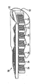
図3は、本発明の好ましい実施例によるコイル組立体30を示す。組立体30は、図1のコイル10のような写真製版コイル32を2個、及びワイヤーコイル34を備える。ワイヤーコイル34は、好ましくは直径が約0.8mm、長さ(L2)が約1.4mmであり、好ましくは巻回数は約400である。コイル32は、その長い方の側辺を互いに隣接しかつ互いにほぼ90゜に揃えられ、実質的に箱の形を定めている。好ましくは、ワイヤーコイル34は、組立体30の幅又は奥行きを大きくさせないように、箱形の長手方向延長部内に位置決めされる。
【0051】
好ましくは、ワイヤーコイル34は、コイルのインダクタンスを大きくするフェライトコア36のまわりに巻かれる。より特別には、フェライトコア36は、長くてかつ狭く、そしてワイヤーコイル34及びコイル32により定められた箱形の双方の中に置かれる。こうして、フェライトコア36は、組立体30内の全てのコイルのインダクタンスを強化する。
【0052】
好ましくは、組立体30は、円筒状のケース38内に囲まれ、このケースの直径は、写真製版コイル32により定められた箱形の対角線とほぼ等しいか又はそれより僅かに大きい。
【0053】
図4は、線IV−IVに沿って得られた図3の組立体の断面を示す。コイルの基板は、コイル32間の共通エッジ33に沿って斜めに切断され、コイル組立体30のために取られる体積を減らすことが好ましい。或いは、基板を直角に切って、一方のコイル32を他方より広く作ることができる。
【0054】
図5は、本発明の別の実施例によるコイル組立体31示す。組立体31は、組立体31のワイヤーコイル34が写真製版コイル32により定められた箱形の中に入れられ、そして恐らくはここからケース38内に伸びることを除いて組立体30と同様である。ワイヤーコイル34は、コイル32の幅(w)より小さい直径、好ましくは約0.4mmを持つ。この実施例では、ワイヤーコイル34は、その小さい直径を補償するために巻回数が約600から800の間であることが好ましい。
【0055】
組立体30は実質的に直交する3個のコイルを有し、即ち、コイルの軸線が互いに実質的に直角であることが観察されるであろう。このため、組立体30は、6自由度の位置判定システムのような装置に普通に使用することができる。組立体30の寸法はコイル32により限定され、この場合、その直径はコイル32の幅(w)により決定され、そして組立体30の長さは実質的にコイル32の長さ(L1)である。
【0056】
図示されない本発明の好ましい実施例においては、組立体30のようなコイル組立体は、カード読取り器から電力を受けかつ情報を送るために、非接触式のスマートカード内に埋設される。磁場に関するカードの向きとは無関係に、カード上に入射する磁場が組立体内にかなりの電流を誘導するように、組立体のコイルは直列に接続されることが好ましい。或いは、コイルを互いに並列に接続することができる。本発明の組立体は、寸法が小さいため、典型的に約0.8mmより大きくない厚さに限定される通常のスマートカード内にこれを挿入することができる。
【0057】
図6は、本発明の別の実施例によるコイル組立体50を示す。組立体50は、図1のコイル10と同様な2個の写真製版コイル52を備える。好ましくは、コイル52は、組立体30と同様な方法で互いに揃えられる。複数の小さいコイル54が、コイル52により定められた箱形の中に設置される。コイル54は、これが箱形の中に適合するように幅と長さは小さいがコイル52と同様であることが好ましい。コイル54は直列に接続されることが好ましい。コイル54の小さい寸法は多数のコイルの使用により補償される。好ましくは、コイル54は、共通の軸線を有し、この軸線がコイル52の軸線と直交し、コイル52と共に3個の直交センサーを形成することが好ましい。
【0058】
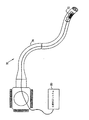
図7は、本発明の好ましい実施例による写真製版コイル組立体72を備えたカテーテル70を示す。カテーテル70は、患者の体内に挿入される挿入管74を備える。コイル組立体72は、好ましくは上述の組立体30又は31と同様な小型組立体であり、かつ好ましくは挿入管74の末端に隣接して設置される。例えば、上述のPCT文書WO96/05768号において説明されたように、組立体72内のコイルは、これに加えられる外部の磁場に応答して信号を発生する。コイル組立体72に組み合わせられた位置判定システム80は、この信号を受け、コイル組立体の位置及び方向の座標、従ってカテーテルの位置及び方向を判定する。
【0059】
カテーテルの挿入管の直径は、通常、約1−5mmである。直径3mmの円い挿入管を有するカテーテルの断面積は約7mm2である。組立体72は、約0.6mm2の断面積を有し、従ってカテーテルの断面積の約10%以下を取る。このため、組立体72がカテーテルの機能を実質的に干渉することはない。
【0060】
上述のPCT/IL97/00061号に説明されたように、組立体72は、磁気的な位置判定に干渉する恐れのあるカテーテル70内の金属及びその他の物質から距離を空けられる。組立体72は、幅が小さいため、他のセンサー組立体よりも干渉物質から大きく離れることができる。内視鏡は、金属物質を有する挿入管を備えることが多い。これらの挿入管は、通常、約12−15mmの直径を持つ。挿入管が約8mmの直径の金属コアを持つならば、この金属コアとコイル組立体72との間を2.5mm以上離すことが可能である。かかる分離は、管の位置判定の際の金属コアにより生ずる干渉を大きく減らすに十分である。
【0061】
カテーテル内への組立体72の挿入は簡単であり、カテーテルの特別な設計特性は何も必要でないことに注意されたい。従って、組立体72は、カテーテルの設計の比較的最小の変更により現存のカテーテル内に挿入することができる。
【0062】
以上説明された好ましい実施例は、例示のため引用されたものであり、本発明の完全な範囲は請求項によってのみ限定されることが認められるであろう。
【0063】
本発明の実施態様は以下のとおりである。
【0064】
1.複数のコイルを備えた磁気波の送信及び受信用の小型コイル組立体であって、各コイルはそれぞれの軸線を有し、少なくも2個の軸線が相互に1次(linearly)独立性であるように、そして複数のコイルの全てが1.0mm2より小さい断面積を有する体積内に収容されるように組み立てられるコイル組立体。
【0065】
2.複数のコイルの全てが0.8mm2より小さい断面積を有する体積内に収容される実施態様1のコイル組立体。
【0066】
3.複数のコイルの全てが0.65mm2より小さい断面積を有する体積内に収容される実施態様2のコイル組立体。
【0067】
4.コイルの少なくも2個が写真製版コイルよりなる実施態様1のコイル組立体。
【0068】
5.前記少なくも2個の写真製版コイルが、それぞれ相互に1次独立性である軸線を有する実施態様4のコイル組立体。
【0069】
6.写真製版コイルが0.8mmより小さい幅を有する実施態様5のコイル組立体。
【0070】
7.写真製版コイルが0.65mmより小さい幅を有する実施態様5のコイル組立体。
【0071】
8.2個の写真製版コイルの軸線が相互に実質的に直交する実施態様5のコイル組立体。
【0072】
9.第3のコイルを備え、第3のコイルの軸線及び2個の写真製版コイルの軸線が相互に1次独立性である実施態様8のコイル組立体。
【0073】
10.第3のコイルの軸線が2個の写真製版コイルの軸線と実質的に直交する実施態様9のコイル組立体。
【0074】
11.第3のコイルが巻線コイルである実施態様10のコイル組立体。
【0075】
12.第3のコイルが相互に接続された複数の写真製版回路よりなる実施態様9のコイル組立体。
【0076】
13.2個の写真製版コイルが長辺と短辺とを有する長方形の基板を備え、そして2個の写真製版コイルは、2個のコイルの長辺が互いに隣接するように揃えられる実施態様4のコイル組立体。
【0077】
14.2個の写真製版コイルの基板が互いに実質的に直角に揃えられる実施態様13のコイル組立体。
【0078】
15.組立体が1.1mmより小さい直径を有する円筒状体積により囲まれる実施態様14のコイル組立体。
【0079】
16.円筒状体積が0.9mmより小さい直径を有する実施態様15のコイル組立体。
【0080】
17.コイルのインダクタンスを強化するために前記体積内に強磁性体コアを備える実施態様15のコイル組立体。
【0081】
18.コアが長い楕円体状のフェライトよりなる実施態様17のコイル組立体。
【0082】
19.フェライトが、組立体内の全ての実質的に全てのコイルに対する共通コオとして作用する実施態様18のコイル組立体。
【0083】
20.コイルの座標を判定するために、電磁場に応答してコイルにより発生された信号を受信し、そして信号を解析する位置判定システムを備えた実施態様9のコイル組立体。
【0084】
21.侵襲性の医用プローブの座標を見いだすために、コイルがプローブ内に挿入される実施態様20のコイル組立体。
【0085】
22.座標が6次元の位置及び方向の座標よりなる実施態様21のコイル組立体。
【図面の簡単な説明】
【図1】本発明の好ましい実施例による写真製版コイルの図式的な斜視図である。
【図2】図1の写真製版コイルの図式的な拡大図である。
【図3】本発明の好ましい実施例による写真製版コイルの図式的な等角図である。
【図4】線IV−IVに沿って得られた図3の組立体の断面図である。
【図5】本発明の好ましい実施例によるコイル組立体の図式的な断面図である。
【図6】本発明の好ましい実施例によるコイル組立体の図式的な等角図である。
【図7】本発明の好ましい実施例によるコイル組立体を有するカテーテルの図式的な説明図である。
【符号の説明】
10 センサーコイル
12 渦巻
14 基板
20 ループ
26 ワイヤー[0001]
[Industrial application fields]
The present invention relates generally to object tracking systems, and more particularly to a non-contact electromagnetic method and apparatus for tracking the position and orientation of a medical probe.
[0002]
This application is a non-provisional patent application of US co-pending provisional application 60/061269 (patent attorney docket number BIO 0025US).
[0003]
[Prior art and its problems]
In many medical procedures, probes such as endoscopes and catheters are inserted into the patient's body. Such probes are used for a large number of procedures including irreversible surgical procedures such as excision and removal of tissue specimens. For this reason, it is necessary to have accurate information about the position and orientation of the probe in the patient's body.
[0004]
The electromagnetic position determination system provides an easy way to receive accurate information on the position and orientation of internal objects and allow accurate tracking of these objects. Such systems are described, for example, in US Pat. Nos. 5558091, 5391199, and 543489, and international patent applications WO 94/04938 and WO 96/05768, the disclosures of which are incorporated herein by reference. These systems use one or more field sensors such as Hall effect instruments, coils carried on the probe, or antennas to determine the coordinates of the probe. The transducer is typically placed at or near the end of the probe and / or along the length of the probe. Therefore, the transducer is preferably made as small as possible to fit within the probe without interfering with the operability of the probe or without unduly increasing its dimensions.
[0005]
U.S. Pat. No. 5,580,091 describes a rectangular Hall effect sensor assembly having three thin galvano magnetic films orthogonal to each other. This sensor assembly preferably has dimensions of about 3 × 0.75 × 0.75 mm. The 5558091 patent further describes another Hall effect sensor assembly having three field sensing elements in the form of a semiconductor chip. Each chip has a long bar of one or more electromagnetic resistance materials. Each chip is sensitive to the component of the electromagnetic field in the direction of this bar. This assembly preferably has a diameter of 0.8 mm or less. However, such chips are subject to non-linear, saturation effects, hysteresis and temperature drift.
[0006]
For this reason, the majority of magnetic position determination systems use a sensor formed of a small coil of a conductor wire having a large number of turns. Such coils are described in, for example, PCT documents PCT / GB93 / 01736, WO94 / 04938, and WO96 / 05768, and the above-mentioned US Pat. Described in. All of these documents are hereby incorporated by reference. The performance of the sensor coil depends on its inductance, which is a function of the product of the number of coil turns and the cross-sectional area of the coil. For this reason, in designing a small coil for use within a surgical probe, it is generally necessary to make a compromise between, for example, the dimensions and performance of the coil. Such coils typically have a minimum dimension of 0.6 × 0.6 × 0.6 mm, more commonly 0.8 × 0.8 × 0.8 mm. Smaller coils in the same format do not provide acceptable performance and are difficult to manufacture.
[0007]
In order to determine both the translational and rotational coordinates, certain position determination systems, such as those described in PCT document WO 96/05768 above, are each linearly independent of each other and preferably orthogonal to each other. Three sensor coils having each axis are used. Preferably, the three coils are packaged together to form a sensor assembly, which is used to provide a 6-dimensional position and orientation coordinate reading. The use of this assembly with three coils in one package facilitates insertion and / or attachment of the coil to the catheter. This assembly also provides accurate positioning between the coils and simplifies the calibration of the position determination system using the coils. Generally, the coil is enclosed in a cylindrical case that protects the coil from the environment.
[0008]
In the PCT / WO 96/05768 system, the assembly is typically about 6 mm in length and about 1.3 mm in diameter. In order to obtain accurate position sensing in all six dimensions, it is impossible to make the assembly diameter smaller, since the coil axes are generally required to be orthogonal to each other.
[0009]
Although this coil assembly fits within the majority of medical probes, in some cases, a coil with comparable and smaller width is desired. For example, PCT Patent Application No. PCT / IL97 / 00061, assigned to the assignee of the present application and incorporated herein by reference, is a small position sensing coil by separating the coil from a metal instrument in the endoscope. A method for improving the accuracy of position determination of an endoscope having a function will be described. If the coil assembly can be made with a smaller width, the distance between the small coil and the metal instrument can be further increased, so that better accuracy is achieved with this position determination system.
[0010]
By reducing the width of the coil assembly, the position determination system can be used with a narrow probe that generally has excellent operability and can easily access distant locations. Alternatively, by reducing the width of the coil assembly, the assembly can occupy a smaller portion of the cross-sectional area of the probe, leaving more space for the functional device and / or a working path along the probe. .
[0011]
Coils made by photoengraving or VLSI techniques are well known in the art. In the following description and embodiments, these coils are referred to as photoengraving coils. Photoengraving coils are generally made in the form of spiral conductors printed on a substrate of plastic, ceramic or semiconductor material. Such coils typically consist of up to four overlapping spiral layers using currently available construction techniques.
[0012]
Photoengraving coils or antennas are also commonly used in contactless smart cards as known in the art. These cards inductively communicate with and receive power from the reader circuit by means of a photoengraving coil or antenna embedded in the card. Since smart cards are limited to a thickness of 0.8 mm or less, they generally have only one coil and their axis needs to be perpendicular to the card surface. In order to communicate with the reader, the smart card needs to be properly oriented so that the coil axis is aligned with the magnetic field created by the reader in order to achieve proper connection.
[0013]
[Means for Solving the Problems]
It is an object of one aspect of the present invention to provide a sensor coil that is thin but has high sensitivity and / or high Q factor.
[0014]
It is another object of certain aspects of the present invention to provide a coil assembly having three orthogonal coils having a narrow and long shape.
[0015]
In a preferred embodiment of the invention, the coil assembly comprises three coils, at least one, preferably two of which are photolithography coils. The coils are first-order independent from one another and preferably the axes are substantially orthogonal to one another. By using these photolithography coils, coil assemblies with smaller diameter, width and / or depth can be formed as described below.
[0016]
In one preferred embodiment of the invention, two of the coils comprise long and narrow photolithography coils. The length of the coil compensates for the narrowness so that the coil encloses an area large enough to provide sufficient inductance for use as a position sensor in the position determination system. Preferably, the width of the coil is 0.8 mm or less, most preferably 0.6 mm or less. The coil thickness is preferably limited only by the photolithography process and is generally about 0.3 mm. In the preferred embodiment of the present invention, the photoengraving coil is made on a flexible substrate so that the assembly does not limit the flexibility of the catheter supporting the assembly.
[0017]
In a preferred embodiment of the present invention, the assembly comprises two long and narrow photomechanical coils which are arranged so that their long sides are adjacent to each other and substantially 90 ° to each other. The photoengraving coil defines a long and narrow box shape with a longitudinal axis, and the coil axes of the two photoengraving coils are substantially perpendicular to this longitudinal axis.
[0018]
Preferably, the substrate of the photoengraving coil is cut obliquely at an angle of about 45 ° so as to be adjacent to each other at an oblique cut portion of the substrate. This connection saves space and minimizes the space occupied by the assembly.
[0019]
A third coil, preferably a small wound coil, is positioned with its coil axis along the longitudinal axis. Preferably, the third coil is outside the box and is adjacent so as to substantially minimize the width and depth of the assembly. Alternatively, the diameter of the wire coil is smaller than the width of the photolithography coil and the wire coil is placed in a box defined by the photolithography coil. Thus, the coil assembly has a narrow width and depth, preferably less than 0.8 mm, most preferably less than about 0.6 mm, so that the diameter of the cylinder surrounding the assembly is less than about 0.9 mm. Not big. Therefore, the cross-sectional area of the assembly is preferably 1 mm. 2 Smaller, more preferably 0.8 mm 2 Smaller and most preferably 0.65mm 2 Smaller than.
[0020]
Preferably, a long ellipsoidal ferrite core is accommodated within an angle formed by two photolithography coils. Preferably, the wire coil is also wound around a core, most preferably a long ellipsoidal core. The ferrite core increases the inductance of the assembly and thus the sensitivity of the coil assembly. Preferably, the assembly is enclosed in a cylindrical case that protects the coil from the environment.
[0021]
In another preferred embodiment of the invention, a plurality of small photolithography coils are used to form the third coil. This small coil is placed parallel to each other and perpendicular to the first two coils in a box defined by the coils as described above. The small coils are preferably rectangular with a width of about 0.4 mm so as not to protrude from the box or the cylinder surrounding the box. Alternatively, the plurality of photoengraving coils are positioned along their longitudinal axis, but outside the box shape of the first two coils.
[0022]
In one preferred embodiment of the invention, the coil assembly comprises three photoengraving coils, each axis being linearly independent from each other.
[0023]
In one preferred embodiment of the invention, one or more photoengraving coil assemblies as described above are placed in a medical probe to determine the coordinates of the probe, preferably 6-dimensional position and orientation. forgive. In these assemblies, each coil preferably has a separate wire connection so that the sensed effect of the external electromagnetic field in each coil is determined independently. The position determination system determines the position and orientation of the assembly based on all sensed effects of the three coils, for example as described in the above-mentioned patent publication WO 96/05768.
[0024]
By using an assembly having a photoengraving coil, the diameter of the cylinder surrounding the coil can be significantly reduced. This reduced diameter allows the assembly to be easily mounted or embedded within the probe. Smaller assemblies allow the use of smaller probes and / or reduce the interference between the working passages and functional devices in the probe and the assembly. Also, the small width and thickness of the coil allows for greater separation between the metal device and the coil within the probe, thereby minimizing interference with the operation of the position determination system.
[0025]
In another preferred embodiment of the present invention, a photoengraving coil assembly is used for inductive transmission of power and / or information. In these preferred embodiments, the three coils in the assembly are preferably connected together in series or parallel. Such inductive transmission is used in smart cards as described above, for example. This makes it particularly suitable for use in smart cards where the narrow width of the photoengraving coil assembly generally requires a thickness of less than 0.8 mm. The use of this coil assembly makes the connection between the smart card and the reader substantially insensitive to the angle between the smart card and the reader. This is because the axes of the coil assemblies are primary independent of each other.
[0026]
Similarly, such a photoengraving coil assembly may be used, for example, in a device for determining the position of a tube in a body as described in the PCT patent application dated September 15, 1997, "Position determination by learning and testing functions" be able to. This application is filed as US patent application Ser. No. 09/079338 (Applicant, Case No. BIO 505.1 US), assigned to the assignee of the present invention, and incorporated herein by reference.
[0027]
A small coil assembly having a plurality of coils for transmitting or receiving magnetic waves, each coil having its own axis, so that at least two axes are primary independent of each other And all of the coils are substantially 1.0mm. 2 Or less, preferably substantially 0.8 mm 2 Less than, and most preferably substantially 0.65 mm 2 A coil assembly assembled to be received within a volume having the following cross-sectional area is provided.
[0028]
Preferably, at least two coils have photoengraving coils.
[0029]
Furthermore, a preferred embodiment of the present invention provides a miniature coil assembly for transmitting and receiving magnetic waves having two photoengraving coils having axes that are linearly independent from each other.
[0030]
The photoengraving coil preferably has a width of less than 0.8 mm, more preferably less than 0.65 mm.
[0031]
It is preferred that the axes of the two photolithography coils are substantially orthogonal.
[0032]
In a preferred embodiment of the invention, the assembly has a third coil, and the axis of the third coil and the axes of the two photoengraving coils are primary independent of each other. Preferably, the axis of the third coil is substantially perpendicular to the axes of the two photoengraving coils.
[0033]
In a preferred embodiment, the third coil is a wound coil, while in another preferred embodiment, the third coil has a plurality of photoengraving circuits connected to each other.
[0034]
Preferably, the two photolithography coils have a long rectangular substrate having a long side and a short side, and the two photolithography coils are aligned so that the long sides of the two coils are adjacent to each other. . Preferably, the substrates of the two photolithography coils are aligned substantially perpendicular to each other.
[0035]
Preferably, the assembly is surrounded by a cylindrical volume having a diameter of less than 1.1 mm, more preferably less than 0.9 mm.
[0036]
In the preferred embodiment, the assembly comprises a ferromagnetic material, preferably a long ellipsoidal ferrite, to enhance the inductance of the coil. Preferably, the ferrite acts as a common core for substantially all coils of the assembly.
[0037]
Preferably, the position determination system receives a signal produced by the coil in response to the electromagnetic field and analyzes this signal to determine the coordinates of the coil. Preferably, a coil is inserted into the invasive medical probe in order to find the coordinates of the probe, preferably 6-dimensional position and method.
[0038]
According to a preferred embodiment of the present invention,
Attach the photoengraving coil assembly to the object, and
Receive signals from the assembly to determine its coordinates
A method for determining the position of an object including the above is also provided.
[0039]
Preferably, the mounting of the assembly includes embedding the photoengraving coil in the object.
[0040]
More preferably, the mounting of the coil assembly is such that the axes of the two coils are primarily independent of each other and substantially 1 mm. 2 Including fixing two photolithography coils each having an axis to an object so as to define a volume having a smaller cross-sectional area.
[0041]
According to a preferred embodiment of the present invention, a probe whose position is tracked in the body of an object,
Insertion tube, and
Photoengraving coil assembly attached to insertion tube
A probe is provided.
[0042]
Preferably, the assembly has a cross-sectional area of substantially 1.0 mm. 2 Contained in a smaller volume.
[0043]
More preferably, the photoengraving coil assembly has at least two photoengraving coils and preferably winding coils, each coil having an axis, the axes being linearly independent from each other, and most preferably Preferably they are substantially orthogonal to each other.
[0044]
In the preferred embodiment of the present invention, the position determination system receives a signal from the coil and analyzes this signal to determine the coordinates of the probe.
[0045]
The invention will be more fully understood from the following detailed description of the preferred embodiments and the drawings.
[0046]
【Example】
1 and 2 show a
[0047]
The
[0048]
The
[0049]
The
[0050]
FIG. 3 shows a
[0051]
Preferably, the
[0052]
Preferably, the
[0053]
FIG. 4 shows a cross section of the assembly of FIG. 3 taken along line IV-IV. The coil substrate is preferably cut diagonally along the
[0054]
FIG. 5 shows a coil assembly 31 according to another embodiment of the present invention. The assembly 31 is similar to the
[0055]
It will be observed that the
[0056]
In a preferred embodiment of the present invention, not shown, a coil assembly, such as
[0057]
FIG. 6 shows a
[0058]
FIG. 7 shows a
[0059]
The diameter of the catheter insertion tube is typically about 1-5 mm. The cross-sectional area of a catheter with a 3 mm diameter round insertion tube is about 7 mm. 2 It is. The
[0060]
As described in PCT / IL97 / 00061 above,
[0061]
Note that the insertion of the
[0062]
It will be appreciated that the preferred embodiments described above are cited by way of illustration and the full scope of the invention is limited only by the claims.
[0063]
Embodiments of the present invention are as follows.
[0064]
1. A miniature coil assembly for transmitting and receiving magnetic waves with multiple coils, each coil having its own axis, and at least two axes are linearly independent of each other And all of the coils are 1.0mm 2 A coil assembly that is assembled to be contained within a volume having a smaller cross-sectional area.
[0065]
2. All of the coils are 0.8mm 2 The coil assembly of embodiment 1 housed in a volume having a smaller cross-sectional area.
[0066]
3. All of the coils are 0.65mm 2 The coil assembly of embodiment 2 housed in a volume having a smaller cross-sectional area.
[0067]
4). The coil assembly according to embodiment 1, wherein at least two of the coils are photolithography coils.
[0068]
5. The coil assembly of embodiment 4 wherein said at least two photoengraving coils each have an axis that is linearly independent of each other.
[0069]
6). The coil assembly of embodiment 5 wherein the photoengraving coil has a width of less than 0.8 mm.
[0070]
7). The coil assembly of embodiment 5 wherein the photoengraving coil has a width of less than 0.65 mm.
[0071]
8. The coil assembly of embodiment 5, wherein the axes of the two photoengraving coils are substantially orthogonal to each other.
[0072]
9. The coil assembly according to embodiment 8, comprising a third coil, wherein the axis of the third coil and the axes of the two photoengraving coils are primary independent of each other.
[0073]
10. The coil assembly according to embodiment 9, wherein the axis of the third coil is substantially perpendicular to the axes of the two photoengraving coils.
[0074]
11. Embodiment 11. The coil assembly of
[0075]
12 The coil assembly according to Embodiment 9, comprising a plurality of photoengraving circuits in which the third coils are connected to each other.
[0076]
13. Embodiment 4 wherein the two photoengraving coils comprise a rectangular substrate having long and short sides, and the two photoengraving coils are aligned so that the long sides of the two coils are adjacent to each other Coil assembly.
[0077]
14. The coil assembly of embodiment 13, wherein the substrates of the two photolithography coils are aligned substantially perpendicular to each other.
[0078]
15. The coil assembly of
[0079]
16.
[0080]
17.
[0081]
18. The coil assembly according to embodiment 17, wherein the core is made of an elliptical ferrite.
[0082]
19. Embodiment 19. The coil assembly of
[0083]
20. 10. The coil assembly of embodiment 9, comprising a position determination system that receives a signal generated by the coil in response to an electromagnetic field and analyzes the signal to determine the coordinates of the coil.
[0084]
21. Embodiment 21. The coil assembly of
[0085]
22. The coil assembly of embodiment 21 wherein the coordinates comprise 6-dimensional position and direction coordinates.
[Brief description of the drawings]
FIG. 1 is a schematic perspective view of a photolithography coil according to a preferred embodiment of the present invention.
FIG. 2 is a schematic enlarged view of the photoengraving coil of FIG.
FIG. 3 is a schematic isometric view of a photolithography coil according to a preferred embodiment of the present invention.
4 is a cross-sectional view of the assembly of FIG. 3 taken along line IV-IV.
FIG. 5 is a schematic cross-sectional view of a coil assembly according to a preferred embodiment of the present invention.
FIG. 6 is a schematic isometric view of a coil assembly according to a preferred embodiment of the present invention.
FIG. 7 is a schematic illustration of a catheter having a coil assembly according to a preferred embodiment of the present invention.
[Explanation of symbols]
10 Sensor coil
12 Swirl
14 Substrate
20 loops
26 wires
Claims (1)
Applications Claiming Priority (2)
| Application Number | Priority Date | Filing Date | Title |
|---|---|---|---|
| US09/160063 | 1998-09-24 | ||
| US09/160,063 US6201387B1 (en) | 1997-10-07 | 1998-09-24 | Miniaturized position sensor having photolithographic coils for tracking a medical probe |
Publications (3)
| Publication Number | Publication Date |
|---|---|
| JP2000121306A JP2000121306A (en) | 2000-04-28 |
| JP2000121306A5 JP2000121306A5 (en) | 2006-06-15 |
| JP4968979B2 true JP4968979B2 (en) | 2012-07-04 |
Family
ID=22575364
Family Applications (1)
| Application Number | Title | Priority Date | Filing Date |
|---|---|---|---|
| JP26568299A Expired - Lifetime JP4968979B2 (en) | 1998-09-24 | 1999-09-20 | Small position sensor |
Country Status (8)
| Country | Link |
|---|---|
| US (1) | US6201387B1 (en) |
| EP (1) | EP0989384B1 (en) |
| JP (1) | JP4968979B2 (en) |
| AU (1) | AU755313B2 (en) |
| CA (1) | CA2283006C (en) |
| DE (1) | DE69928342T2 (en) |
| ES (1) | ES2251160T3 (en) |
| IL (1) | IL131807A (en) |
Families Citing this family (193)
| Publication number | Priority date | Publication date | Assignee | Title |
|---|---|---|---|---|
| FR2652928B1 (en) | 1989-10-05 | 1994-07-29 | Diadix Sa | INTERACTIVE LOCAL INTERVENTION SYSTEM WITHIN A AREA OF A NON-HOMOGENEOUS STRUCTURE. |
| WO1994004938A1 (en) | 1992-08-14 | 1994-03-03 | British Telecommunications Public Limited Company | Position location system |
| DE69531994T2 (en) | 1994-09-15 | 2004-07-22 | OEC Medical Systems, Inc., Boston | SYSTEM FOR POSITION DETECTION BY MEANS OF A REFERENCE UNIT ATTACHED TO A PATIENT'S HEAD FOR USE IN THE MEDICAL AREA |
| US6226548B1 (en) | 1997-09-24 | 2001-05-01 | Surgical Navigation Technologies, Inc. | Percutaneous registration apparatus and method for use in computer-assisted surgical navigation |
| US6021343A (en) | 1997-11-20 | 2000-02-01 | Surgical Navigation Technologies | Image guided awl/tap/screwdriver |
| US6348058B1 (en) | 1997-12-12 | 2002-02-19 | Surgical Navigation Technologies, Inc. | Image guided spinal surgery guide, system, and method for use thereof |
| US6623474B1 (en) * | 1998-06-04 | 2003-09-23 | Biosense Webster, Inc. | Injection catheter with needle stop |
| US8079982B1 (en) | 1998-06-04 | 2011-12-20 | Biosense Webster, Inc. | Injection catheter with needle electrode |
| US6623473B1 (en) * | 1998-06-04 | 2003-09-23 | Biosense Webster, Inc. | Injection catheter with multi-directional delivery injection needle |
| US6477400B1 (en) | 1998-08-20 | 2002-11-05 | Sofamor Danek Holdings, Inc. | Fluoroscopic image guided orthopaedic surgery system with intraoperative registration |
| US6470207B1 (en) | 1999-03-23 | 2002-10-22 | Surgical Navigation Technologies, Inc. | Navigational guidance via computer-assisted fluoroscopic imaging |
| US6491699B1 (en) * | 1999-04-20 | 2002-12-10 | Surgical Navigation Technologies, Inc. | Instrument guidance method and system for image guided surgery |
| US6499488B1 (en) | 1999-10-28 | 2002-12-31 | Winchester Development Associates | Surgical sensor |
| US11331150B2 (en) | 1999-10-28 | 2022-05-17 | Medtronic Navigation, Inc. | Method and apparatus for surgical navigation |
| US7366562B2 (en) | 2003-10-17 | 2008-04-29 | Medtronic Navigation, Inc. | Method and apparatus for surgical navigation |
| US6493573B1 (en) * | 1999-10-28 | 2002-12-10 | Winchester Development Associates | Method and system for navigating a catheter probe in the presence of field-influencing objects |
| US6381485B1 (en) | 1999-10-28 | 2002-04-30 | Surgical Navigation Technologies, Inc. | Registration of human anatomy integrated for electromagnetic localization |
| US8239001B2 (en) | 2003-10-17 | 2012-08-07 | Medtronic Navigation, Inc. | Method and apparatus for surgical navigation |
| US6474341B1 (en) | 1999-10-28 | 2002-11-05 | Surgical Navigation Technologies, Inc. | Surgical communication and power system |
| US8644907B2 (en) | 1999-10-28 | 2014-02-04 | Medtronic Navigaton, Inc. | Method and apparatus for surgical navigation |
| US6725080B2 (en) | 2000-03-01 | 2004-04-20 | Surgical Navigation Technologies, Inc. | Multiple cannula image guided tool for image guided procedures |
| US6535756B1 (en) | 2000-04-07 | 2003-03-18 | Surgical Navigation Technologies, Inc. | Trajectory storage apparatus and method for surgical navigation system |
| US7085400B1 (en) | 2000-06-14 | 2006-08-01 | Surgical Navigation Technologies, Inc. | System and method for image based sensor calibration |
| US6405067B1 (en) | 2000-07-07 | 2002-06-11 | Biosense Webster, Inc. | Catheter with tip electrode having a recessed ring electrode mounted thereon |
| US6477396B1 (en) | 2000-07-07 | 2002-11-05 | Biosense Webster, Inc. | Mapping and ablation catheter |
| US6408199B1 (en) * | 2000-07-07 | 2002-06-18 | Biosense, Inc. | Bipolar mapping of intracardiac potentials with electrode having blood permeable covering |
| US20040087877A1 (en) | 2000-08-23 | 2004-05-06 | Besz William John | Catheter locator apparatus and method of use |
| AU2002307759A1 (en) * | 2001-04-04 | 2002-10-21 | Given Imaging Ltd. | Induction powered in vivo imaging device |
| US20030018251A1 (en) * | 2001-04-06 | 2003-01-23 | Stephen Solomon | Cardiological mapping and navigation system |
| US20040152974A1 (en) * | 2001-04-06 | 2004-08-05 | Stephen Solomon | Cardiology mapping and navigation system |
| US6636757B1 (en) | 2001-06-04 | 2003-10-21 | Surgical Navigation Technologies, Inc. | Method and apparatus for electromagnetic navigation of a surgical probe near a metal object |
| US7286868B2 (en) * | 2001-06-15 | 2007-10-23 | Biosense Inc. | Medical device with position sensor having accuracy at high temperatures |
| US6992477B2 (en) * | 2001-06-15 | 2006-01-31 | Biosense, Inc. | Medical device with position sensor having core with high permeability material for determining location coordinates of a portion of the medical device |
| US20030040670A1 (en) * | 2001-06-15 | 2003-02-27 | Assaf Govari | Method for measuring temperature and of adjusting for temperature sensitivity with a medical device having a position sensor |
| JP3957505B2 (en) * | 2001-12-26 | 2007-08-15 | 株式会社ワコム | 3D information detection device, 3D information sensor device |
| US6947786B2 (en) | 2002-02-28 | 2005-09-20 | Surgical Navigation Technologies, Inc. | Method and apparatus for perspective inversion |
| US6990368B2 (en) | 2002-04-04 | 2006-01-24 | Surgical Navigation Technologies, Inc. | Method and apparatus for virtual digital subtraction angiography |
| US7998062B2 (en) | 2004-03-29 | 2011-08-16 | Superdimension, Ltd. | Endoscope structures and techniques for navigating to a target in branched structure |
| US7560269B2 (en) * | 2002-12-20 | 2009-07-14 | Acea Biosciences, Inc. | Real time electronic cell sensing system and applications for cytotoxicity profiling and compound assays |
| US20040049121A1 (en) * | 2002-09-06 | 2004-03-11 | Uri Yaron | Positioning system for neurological procedures in the brain |
| US7599730B2 (en) | 2002-11-19 | 2009-10-06 | Medtronic Navigation, Inc. | Navigation system for cardiac therapies |
| US7697972B2 (en) | 2002-11-19 | 2010-04-13 | Medtronic Navigation, Inc. | Navigation system for cardiac therapies |
| US7660623B2 (en) | 2003-01-30 | 2010-02-09 | Medtronic Navigation, Inc. | Six degree of freedom alignment display for medical procedures |
| US7542791B2 (en) | 2003-01-30 | 2009-06-02 | Medtronic Navigation, Inc. | Method and apparatus for preplanning a surgical procedure |
| US7839146B2 (en) * | 2003-06-24 | 2010-11-23 | Medtronic, Inc. | Magnetic resonance imaging interference immune device |
| JP2005052637A (en) * | 2003-07-18 | 2005-03-03 | Pentax Corp | Capsule type device and capsule type device driving control system |
| US7354398B2 (en) * | 2003-07-18 | 2008-04-08 | Pentax Corporation | Capsule-type device and capsule-type device controlling system |
| US7313430B2 (en) | 2003-08-28 | 2007-12-25 | Medtronic Navigation, Inc. | Method and apparatus for performing stereotactic surgery |
| ATE438335T1 (en) | 2003-09-15 | 2009-08-15 | Super Dimension Ltd | SYSTEM OF ACCESSORIES FOR USE WITH BRONCHOSCOPES |
| EP2316328B1 (en) | 2003-09-15 | 2012-05-09 | Super Dimension Ltd. | Wrap-around holding device for use with bronchoscopes |
| US7835778B2 (en) * | 2003-10-16 | 2010-11-16 | Medtronic Navigation, Inc. | Method and apparatus for surgical navigation of a multiple piece construct for implantation |
| US7840253B2 (en) | 2003-10-17 | 2010-11-23 | Medtronic Navigation, Inc. | Method and apparatus for surgical navigation |
| WO2005039400A1 (en) * | 2003-10-27 | 2005-05-06 | Olympus Corporation | Capsule type medical device |
| JP2005159607A (en) | 2003-11-25 | 2005-06-16 | Matsushita Electric Ind Co Ltd | Portable communication apparatus |
| US8764725B2 (en) | 2004-02-09 | 2014-07-01 | Covidien Lp | Directional anchoring mechanism, method and applications thereof |
| US20070208252A1 (en) * | 2004-04-21 | 2007-09-06 | Acclarent, Inc. | Systems and methods for performing image guided procedures within the ear, nose, throat and paranasal sinuses |
| US7567834B2 (en) | 2004-05-03 | 2009-07-28 | Medtronic Navigation, Inc. | Method and apparatus for implantation between two vertebral bodies |
| JP4476717B2 (en) * | 2004-06-30 | 2010-06-09 | オークマ株式会社 | Electromagnetic induction type position sensor |
| JP4508820B2 (en) * | 2004-10-19 | 2010-07-21 | 株式会社ワコム | 3D information detection system and 3D information input device |
| US7976518B2 (en) | 2005-01-13 | 2011-07-12 | Corpak Medsystems, Inc. | Tubing assembly and signal generator placement control device and method for use with catheter guidance systems |
| US7959601B2 (en) * | 2005-02-14 | 2011-06-14 | Biosense Webster, Inc. | Steerable catheter with in-plane deflection |
| US7532932B2 (en) * | 2005-03-08 | 2009-05-12 | Kenergy, Inc. | Implantable medical apparatus having an omnidirectional antenna for receiving radio frequency signals |
| WO2007028035A2 (en) | 2005-09-01 | 2007-03-08 | Proteus Biomedical, Inc. | Implantable zero-wire communications system |
| ES2273595B1 (en) * | 2005-09-19 | 2007-12-16 | Bsh Electrodomesticos España, S.A. | DEVICE WITH A SENSOR SYSTEM TO DETERMINE THE POSITION OF A METAL OBJECT. |
| US7835784B2 (en) | 2005-09-21 | 2010-11-16 | Medtronic Navigation, Inc. | Method and apparatus for positioning a reference frame |
| US20070161888A1 (en) * | 2005-12-30 | 2007-07-12 | Sherman Jason T | System and method for registering a bone of a patient with a computer assisted orthopaedic surgery system |
| US8862200B2 (en) * | 2005-12-30 | 2014-10-14 | DePuy Synthes Products, LLC | Method for determining a position of a magnetic source |
| US20070167741A1 (en) * | 2005-12-30 | 2007-07-19 | Sherman Jason T | Apparatus and method for registering a bone of a patient with a computer assisted orthopaedic surgery system |
| US7525309B2 (en) | 2005-12-30 | 2009-04-28 | Depuy Products, Inc. | Magnetic sensor array |
| US7816915B2 (en) * | 2006-01-06 | 2010-10-19 | Biosense Webster, Inc. | Miniature coils on core with printed circuit |
| US9168102B2 (en) | 2006-01-18 | 2015-10-27 | Medtronic Navigation, Inc. | Method and apparatus for providing a container to a sterile environment |
| US7471202B2 (en) | 2006-03-29 | 2008-12-30 | General Electric Co. | Conformal coil array for a medical tracking system |
| US7532997B2 (en) | 2006-04-17 | 2009-05-12 | General Electric Company | Electromagnetic tracking using a discretized numerical field model |
| US8112292B2 (en) | 2006-04-21 | 2012-02-07 | Medtronic Navigation, Inc. | Method and apparatus for optimizing a therapy |
| DE102006029122A1 (en) * | 2006-06-22 | 2007-12-27 | Amedo Gmbh | System for determining the position of a medical instrument |
| FR2903812B1 (en) * | 2006-07-13 | 2008-10-31 | Commissariat Energie Atomique | INTEGRATED CIRCUIT DISTRIBUTED TO AT LEAST TWO NON-PARALLEL PLANS AND METHOD FOR PRODUCING THE SAME |
| US8172762B2 (en) * | 2006-09-01 | 2012-05-08 | Proteus Biomedical, Inc. | Simultaneous blood flow and hematocrit sensor |
| US8197494B2 (en) * | 2006-09-08 | 2012-06-12 | Corpak Medsystems, Inc. | Medical device position guidance system with wireless connectivity between a noninvasive device and an invasive device |
| US8660635B2 (en) | 2006-09-29 | 2014-02-25 | Medtronic, Inc. | Method and apparatus for optimizing a computer assisted surgical procedure |
| WO2008125910A2 (en) | 2006-11-10 | 2008-10-23 | Superdimension, Ltd. | Adaptive navigation technique for navigating a catheter through a body channel or cavity |
| US8068648B2 (en) * | 2006-12-21 | 2011-11-29 | Depuy Products, Inc. | Method and system for registering a bone of a patient with a computer assisted orthopaedic surgery system |
| US20080167639A1 (en) * | 2007-01-08 | 2008-07-10 | Superdimension Ltd. | Methods for localized intra-body treatment of tissue |
| US7508195B2 (en) * | 2007-01-18 | 2009-03-24 | General Electric Company | Anti-distortion electromagnetic sensor method and system |
| US7573258B2 (en) * | 2007-01-18 | 2009-08-11 | General Electric Company | Coil arrangement for electromagnetic tracker method and system |
| JP2008178544A (en) * | 2007-01-24 | 2008-08-07 | Olympus Corp | Wireless feeding system, capsule endoscope and capsule endoscope system |
| JP5331307B2 (en) * | 2007-01-24 | 2013-10-30 | オリンパス株式会社 | Capsule endoscope and capsule endoscope system |
| US7782046B2 (en) | 2007-02-05 | 2010-08-24 | General Electric Company | Electromagnetic tracking method and system |
| US8249689B2 (en) * | 2007-02-23 | 2012-08-21 | General Electric Company | Coil arrangement for electromagnetic tracking method and system |
| US7902817B2 (en) * | 2007-03-26 | 2011-03-08 | General Electric Company | Electromagnetic tracking method and system |
| US9055883B2 (en) * | 2007-05-16 | 2015-06-16 | General Electric Company | Surgical navigation system with a trackable ultrasound catheter |
| US8603046B2 (en) * | 2007-05-23 | 2013-12-10 | Biosense Webster, Inc. | Automated injection catheter device and system |
| US8480653B2 (en) | 2007-05-23 | 2013-07-09 | Biosense Webster, Inc. | Magnetically guided catheter with concentric needle port |
| US8192399B2 (en) * | 2007-05-23 | 2012-06-05 | Biosense Webster, Inc. | Extension control handle with adjustable locking mechanism |
| WO2009074872A2 (en) * | 2007-07-09 | 2009-06-18 | Superdimension, Ltd. | Patent breathing modeling |
| US7834621B2 (en) * | 2007-09-25 | 2010-11-16 | General Electric Company | Electromagnetic tracking employing scalar-magnetometer |
| US8905920B2 (en) | 2007-09-27 | 2014-12-09 | Covidien Lp | Bronchoscope adapter and method |
| US8357152B2 (en) | 2007-10-08 | 2013-01-22 | Biosense Webster (Israel), Ltd. | Catheter with pressure sensing |
| US8535308B2 (en) | 2007-10-08 | 2013-09-17 | Biosense Webster (Israel), Ltd. | High-sensitivity pressure-sensing probe |
| US8391952B2 (en) * | 2007-10-11 | 2013-03-05 | General Electric Company | Coil arrangement for an electromagnetic tracking system |
| US20090118620A1 (en) * | 2007-11-06 | 2009-05-07 | General Electric Company | System and method for tracking an ultrasound catheter |
| US8926511B2 (en) * | 2008-02-29 | 2015-01-06 | Biosense Webster, Inc. | Location system with virtual touch screen |
| US9575140B2 (en) | 2008-04-03 | 2017-02-21 | Covidien Lp | Magnetic interference detection system and method |
| US8218846B2 (en) | 2008-05-15 | 2012-07-10 | Superdimension, Ltd. | Automatic pathway and waypoint generation and navigation method |
| US8473032B2 (en) | 2008-06-03 | 2013-06-25 | Superdimension, Ltd. | Feature-based registration method |
| US8437832B2 (en) | 2008-06-06 | 2013-05-07 | Biosense Webster, Inc. | Catheter with bendable tip |
| US8218847B2 (en) | 2008-06-06 | 2012-07-10 | Superdimension, Ltd. | Hybrid registration method |
| US8932207B2 (en) | 2008-07-10 | 2015-01-13 | Covidien Lp | Integrated multi-functional endoscopic tool |
| US9101734B2 (en) * | 2008-09-09 | 2015-08-11 | Biosense Webster, Inc. | Force-sensing catheter with bonded center strut |
| US8165658B2 (en) | 2008-09-26 | 2012-04-24 | Medtronic, Inc. | Method and apparatus for positioning a guide relative to a base |
| JP5195336B2 (en) * | 2008-11-14 | 2013-05-08 | 株式会社ジェイテクト | Displacement sensor device and rolling bearing device |
| US8175681B2 (en) | 2008-12-16 | 2012-05-08 | Medtronic Navigation Inc. | Combination of electromagnetic and electropotential localization |
| US9326700B2 (en) | 2008-12-23 | 2016-05-03 | Biosense Webster (Israel) Ltd. | Catheter display showing tip angle and pressure |
| US8600472B2 (en) * | 2008-12-30 | 2013-12-03 | Biosense Webster (Israel), Ltd. | Dual-purpose lasso catheter with irrigation using circumferentially arranged ring bump electrodes |
| US8475450B2 (en) | 2008-12-30 | 2013-07-02 | Biosense Webster, Inc. | Dual-purpose lasso catheter with irrigation |
| DE102009022992A1 (en) * | 2009-03-02 | 2010-10-07 | Micro-Epsilon Messtechnik Gmbh & Co. Kg | position sensor |
| US9226688B2 (en) | 2009-03-10 | 2016-01-05 | Medtronic Xomed, Inc. | Flexible circuit assemblies |
| US9226689B2 (en) | 2009-03-10 | 2016-01-05 | Medtronic Xomed, Inc. | Flexible circuit sheet |
| US8504139B2 (en) | 2009-03-10 | 2013-08-06 | Medtronic Xomed, Inc. | Navigating a surgical instrument |
| US8611984B2 (en) | 2009-04-08 | 2013-12-17 | Covidien Lp | Locatable catheter |
| US8450997B2 (en) * | 2009-04-28 | 2013-05-28 | Brown University | Electromagnetic position and orientation sensing system |
| US8494613B2 (en) | 2009-08-31 | 2013-07-23 | Medtronic, Inc. | Combination localization system |
| US8494614B2 (en) | 2009-08-31 | 2013-07-23 | Regents Of The University Of Minnesota | Combination localization system |
| US9008574B2 (en) * | 2009-09-14 | 2015-04-14 | Qualcomm Incorporated | Focused antenna, multi-purpose antenna, and methods related thereto |
| US9101733B2 (en) * | 2009-09-29 | 2015-08-11 | Biosense Webster, Inc. | Catheter with biased planar deflection |
| CN102892364B (en) * | 2009-10-06 | 2016-03-16 | 史密夫和内修有限公司 | Aim at the mark of orthopaedic instrumentation |
| US10688278B2 (en) | 2009-11-30 | 2020-06-23 | Biosense Webster (Israel), Ltd. | Catheter with pressure measuring tip |
| US8920415B2 (en) * | 2009-12-16 | 2014-12-30 | Biosense Webster (Israel) Ltd. | Catheter with helical electrode |
| US8521462B2 (en) | 2009-12-23 | 2013-08-27 | Biosense Webster (Israel), Ltd. | Calibration system for a pressure-sensitive catheter |
| US8529476B2 (en) | 2009-12-28 | 2013-09-10 | Biosense Webster (Israel), Ltd. | Catheter with strain gauge sensor |
| US8608735B2 (en) * | 2009-12-30 | 2013-12-17 | Biosense Webster (Israel) Ltd. | Catheter with arcuate end section |
| US8374670B2 (en) * | 2010-01-22 | 2013-02-12 | Biosense Webster, Inc. | Catheter having a force sensing distal tip |
| EP2531953B1 (en) | 2010-02-01 | 2018-07-11 | Covidien LP | Region-growing algorithm |
| EP3563788A1 (en) | 2010-04-30 | 2019-11-06 | Medtronic Xomed, Inc. | Navigated malleable surgical instrument |
| US8798952B2 (en) | 2010-06-10 | 2014-08-05 | Biosense Webster (Israel) Ltd. | Weight-based calibration system for a pressure sensitive catheter |
| US10582834B2 (en) | 2010-06-15 | 2020-03-10 | Covidien Lp | Locatable expandable working channel and method |
| DE102010025379A1 (en) * | 2010-06-28 | 2011-12-29 | Technische Universität Dortmund | Method for detecting and warning of wrong-way drivers as well as wrong-way reporting and warning system |
| US8226580B2 (en) | 2010-06-30 | 2012-07-24 | Biosense Webster (Israel), Ltd. | Pressure sensing for a multi-arm catheter |
| US8380276B2 (en) | 2010-08-16 | 2013-02-19 | Biosense Webster, Inc. | Catheter with thin film pressure sensing distal tip |
| US8731859B2 (en) | 2010-10-07 | 2014-05-20 | Biosense Webster (Israel) Ltd. | Calibration system for a force-sensing catheter |
| US8979772B2 (en) | 2010-11-03 | 2015-03-17 | Biosense Webster (Israel), Ltd. | Zero-drift detection and correction in contact force measurements |
| US9974501B2 (en) | 2011-01-28 | 2018-05-22 | Medtronic Navigation, Inc. | Method and apparatus for image-based navigation |
| US10492868B2 (en) | 2011-01-28 | 2019-12-03 | Medtronic Navigation, Inc. | Method and apparatus for image-based navigation |
| US10617374B2 (en) | 2011-01-28 | 2020-04-14 | Medtronic Navigation, Inc. | Method and apparatus for image-based navigation |
| US8430864B2 (en) | 2011-02-16 | 2013-04-30 | Biosense Webster, Inc. | Catheter with multiple deflections |
| US8333103B2 (en) * | 2011-03-30 | 2012-12-18 | Biosense Webster (Israel), Ltd. | Calibration of a force measuring system for large bend angles of a catheter |
| US9220433B2 (en) | 2011-06-30 | 2015-12-29 | Biosense Webster (Israel), Ltd. | Catheter with variable arcuate distal section |
| US9662169B2 (en) | 2011-07-30 | 2017-05-30 | Biosense Webster (Israel) Ltd. | Catheter with flow balancing valve |
| WO2013036772A1 (en) | 2011-09-08 | 2013-03-14 | Corpak Medsystems, Inc. | Apparatus and method used with guidance system for feeding and suctioning |
| US10258255B2 (en) * | 2011-09-14 | 2019-04-16 | St. Jude Medical International Holding S.àr.l. | Method for producing a miniature electromagnetic coil using flexible printed circuitry |
| US9750486B2 (en) | 2011-10-25 | 2017-09-05 | Medtronic Navigation, Inc. | Trackable biopsy needle |
| US9427172B2 (en) | 2011-12-30 | 2016-08-30 | Mediguide Ltd. | Roll detection and six degrees of freedom sensor assembly |
| US9687289B2 (en) | 2012-01-04 | 2017-06-27 | Biosense Webster (Israel) Ltd. | Contact assessment based on phase measurement |
| US8929810B2 (en) | 2012-04-23 | 2015-01-06 | Qualcomm Incorporated | Methods and apparatus for improving NFC connection through device positioning |
| US9179971B2 (en) | 2013-02-11 | 2015-11-10 | St. Jude Medical, Atrial Fibrillation Division, Inc. | Printed electrode catheter |
| US10278729B2 (en) | 2013-04-26 | 2019-05-07 | Medtronic Xomed, Inc. | Medical device and its construction |
| EP3476287B1 (en) | 2014-01-28 | 2022-02-23 | St. Jude Medical, Cardiology Division, Inc. | Method of manufacture of a catheter shaft with electrically-conductive traces |
| JP6415589B2 (en) | 2014-01-28 | 2018-10-31 | セント・ジュード・メディカル・インターナショナル・ホールディング・エスエーアールエルSt. Jude Medical International Holding S.a,r.l. | Medical device with packaged electronic subassembly and method of manufacturing the same |
| EP3082588B8 (en) * | 2014-01-28 | 2018-12-19 | St. Jude Medical International Holding S.à r.l. | Elongate medical devices incorporating a flexible substrate, a sensor, and electrically-conductive traces |
| US10952593B2 (en) | 2014-06-10 | 2021-03-23 | Covidien Lp | Bronchoscope adapter |
| JP6534193B2 (en) | 2014-07-02 | 2019-06-26 | コヴィディエン リミテッド パートナーシップ | Real-time automatic registration feedback |
| WO2016004030A1 (en) | 2014-07-02 | 2016-01-07 | Covidien Lp | System and method for segmentation of lung |
| CN111449669B (en) | 2014-07-02 | 2023-04-18 | 柯惠有限合伙公司 | System and method for detecting trachea |
| US9770216B2 (en) | 2014-07-02 | 2017-09-26 | Covidien Lp | System and method for navigating within the lung |
| US20160000414A1 (en) | 2014-07-02 | 2016-01-07 | Covidien Lp | Methods for marking biopsy location |
| US9754367B2 (en) | 2014-07-02 | 2017-09-05 | Covidien Lp | Trachea marking |
| US9603668B2 (en) | 2014-07-02 | 2017-03-28 | Covidien Lp | Dynamic 3D lung map view for tool navigation inside the lung |
| JP6769978B2 (en) * | 2014-11-18 | 2020-10-14 | スミス アンド ネフュー インコーポレイテッド | Endoscopic systems and methods for operating endoscopic systems |
| US10426555B2 (en) | 2015-06-03 | 2019-10-01 | Covidien Lp | Medical instrument with sensor for use in a system and method for electromagnetic navigation |
| US10986990B2 (en) | 2015-09-24 | 2021-04-27 | Covidien Lp | Marker placement |
| US10709352B2 (en) | 2015-10-27 | 2020-07-14 | Covidien Lp | Method of using lung airway carina locations to improve ENB registration |
| US9962134B2 (en) | 2015-10-28 | 2018-05-08 | Medtronic Navigation, Inc. | Apparatus and method for maintaining image quality while minimizing X-ray dosage of a patient |
| US10687709B2 (en) | 2016-05-09 | 2020-06-23 | Integrated Sensing Systems, Inc. | Implantable sensing devices and anchoring methods therefor |
| US10478254B2 (en) | 2016-05-16 | 2019-11-19 | Covidien Lp | System and method to access lung tissue |
| US20190223758A1 (en) * | 2016-08-24 | 2019-07-25 | St. Jude Medical International Holding S.À R.L. | Composite planarity member with integrated tracking sensors |
| US10615500B2 (en) | 2016-10-28 | 2020-04-07 | Covidien Lp | System and method for designing electromagnetic navigation antenna assemblies |
| US10638952B2 (en) | 2016-10-28 | 2020-05-05 | Covidien Lp | Methods, systems, and computer-readable media for calibrating an electromagnetic navigation system |
| US10792106B2 (en) | 2016-10-28 | 2020-10-06 | Covidien Lp | System for calibrating an electromagnetic navigation system |
| US10517505B2 (en) | 2016-10-28 | 2019-12-31 | Covidien Lp | Systems, methods, and computer-readable media for optimizing an electromagnetic navigation system |
| US10722311B2 (en) | 2016-10-28 | 2020-07-28 | Covidien Lp | System and method for identifying a location and/or an orientation of an electromagnetic sensor based on a map |
| US10418705B2 (en) | 2016-10-28 | 2019-09-17 | Covidien Lp | Electromagnetic navigation antenna assembly and electromagnetic navigation system including the same |
| US10751126B2 (en) | 2016-10-28 | 2020-08-25 | Covidien Lp | System and method for generating a map for electromagnetic navigation |
| US10446931B2 (en) | 2016-10-28 | 2019-10-15 | Covidien Lp | Electromagnetic navigation antenna assembly and electromagnetic navigation system including the same |
| US10918306B2 (en) * | 2016-12-13 | 2021-02-16 | Biosense Webster (Israel) Ltd. | Catheter splines with embedded circuit elements |
| US10251580B2 (en) * | 2017-02-01 | 2019-04-09 | Rock West Medical Devices, Llc | Flexible circuit for a swallowable pill |
| US11304642B2 (en) | 2017-02-15 | 2022-04-19 | Biosense Webster (Israel) Ltd. | Multi-axial position sensors printed on a folded flexible circuit board |
| WO2018150374A1 (en) * | 2017-02-17 | 2018-08-23 | St. Jude Medical International Holding S.À R.L. | Sensor coil assembly |
| US20180311467A1 (en) * | 2017-04-27 | 2018-11-01 | Ehsan Shameli | Mechanical Force Sensor Based on Eddy Current Sensing |
| US11219489B2 (en) | 2017-10-31 | 2022-01-11 | Covidien Lp | Devices and systems for providing sensors in parallel with medical tools |
| EP3479757A1 (en) * | 2017-11-07 | 2019-05-08 | Integrated Sensing Systems, Inc. | Implantable sensing devices and anchoring methods therefor |
| US10695109B2 (en) | 2017-12-13 | 2020-06-30 | DePuy Synthes Products, Inc. | Intramedullary nail with cannulation access hole |
| WO2019143612A1 (en) * | 2018-01-16 | 2019-07-25 | Boston Scientific Scimed, Inc. | Electrical arrangements for sensor assemblies in electromagnetic navigation systems |
| US11224392B2 (en) | 2018-02-01 | 2022-01-18 | Covidien Lp | Mapping disease spread |
| WO2020194212A1 (en) * | 2019-03-26 | 2020-10-01 | St. Jude Medical International Holding S.À R.L. | Off-axis magnetic position sensor assembly |
Family Cites Families (25)
| Publication number | Priority date | Publication date | Assignee | Title |
|---|---|---|---|---|
| US3868565A (en) | 1973-07-30 | 1975-02-25 | Jack Kuipers | Object tracking and orientation determination means, system and process |
| US4054881A (en) | 1976-04-26 | 1977-10-18 | The Austin Company | Remote object position locater |
| US4245207A (en) * | 1977-05-20 | 1981-01-13 | Toko, Inc. | Miniature high frequency coil assembly or transformer |
| JPS59672A (en) * | 1982-06-27 | 1984-01-05 | Tsutomu Jinno | Distance measuring sensor |
| DE3230792C2 (en) | 1982-08-19 | 1986-10-23 | Nax GmbH & Co Ladenbau KG, 6000 Frankfurt | Refrigerated counter unit |
| US4613866A (en) | 1983-05-13 | 1986-09-23 | Mcdonnell Douglas Corporation | Three dimensional digitizer with electromagnetic coupling |
| US4642786A (en) | 1984-05-25 | 1987-02-10 | Position Orientation Systems, Ltd. | Method and apparatus for position and orientation measurement using a magnetic field and retransmission |
| DE3914619A1 (en) | 1989-05-03 | 1990-11-08 | Kontron Elektronik | DEVICE FOR TRANSOESOPHAGEAL ECHOCARDIOGRAPHY |
| EP0419729A1 (en) | 1989-09-29 | 1991-04-03 | Siemens Aktiengesellschaft | Position finding of a catheter by means of non-ionising fields |
| FR2659178B1 (en) * | 1990-03-02 | 1992-05-15 | Ebauchesfabrik Eta Ag | DRIVING COIL ASSEMBLY, METHOD FOR MANUFACTURING SUCH AN ASSEMBLY, AND ELECTROMAGNETIC MICROMOTOR EQUIPPED WITH SAME. |
| JP2750201B2 (en) | 1990-04-13 | 1998-05-13 | オリンパス光学工業株式会社 | Endoscope insertion state detection device |
| US5253647A (en) | 1990-04-13 | 1993-10-19 | Olympus Optical Co., Ltd. | Insertion position and orientation state pickup for endoscope |
| KR960006848B1 (en) * | 1990-05-31 | 1996-05-23 | 가부시끼가이샤 도시바 | Plane magnetic elements |
| JP3441082B2 (en) * | 1990-05-31 | 2003-08-25 | 株式会社東芝 | Planar magnetic element |
| GB9018660D0 (en) | 1990-08-24 | 1990-10-10 | Imperial College | Probe system |
| US5211165A (en) | 1991-09-03 | 1993-05-18 | General Electric Company | Tracking system to follow the position and orientation of a device with radiofrequency field gradients |
| US5425367A (en) | 1991-09-04 | 1995-06-20 | Navion Biomedical Corporation | Catheter depth, position and orientation location system |
| US5341807A (en) | 1992-06-30 | 1994-08-30 | American Cardiac Ablation Co., Inc. | Ablation catheter positioning system |
| WO1994004938A1 (en) | 1992-08-14 | 1994-03-03 | British Telecommunications Public Limited Company | Position location system |
| US5391199A (en) | 1993-07-20 | 1995-02-21 | Biosense, Inc. | Apparatus and method for treating cardiac arrhythmias |
| US5558091A (en) * | 1993-10-06 | 1996-09-24 | Biosense, Inc. | Magnetic determination of position and orientation |
| DE4407785A1 (en) * | 1994-03-09 | 1995-09-14 | Philips Patentverwaltung | Arrangement for determining the spatial position of a scanning element displaceable relative to a reference element |
| US5786690A (en) * | 1994-08-18 | 1998-07-28 | International Business Machines Corporation | High resolution three-axis scanning squid microscope having planar solenoids |
| ES2210662T3 (en) | 1994-08-19 | 2004-07-01 | Biosense, Inc. | MEDICAL SYSTEMS OF DIAGNOSIS, TREATMENT AND IMAGE. |
| US5729129A (en) | 1995-06-07 | 1998-03-17 | Biosense, Inc. | Magnetic location system with feedback adjustment of magnetic field generator |
-
1998
- 1998-09-24 US US09/160,063 patent/US6201387B1/en not_active Expired - Lifetime
-
1999
- 1999-09-08 IL IL13180799A patent/IL131807A/en not_active IP Right Cessation
- 1999-09-16 AU AU48768/99A patent/AU755313B2/en not_active Expired
- 1999-09-20 JP JP26568299A patent/JP4968979B2/en not_active Expired - Lifetime
- 1999-09-22 CA CA002283006A patent/CA2283006C/en not_active Expired - Lifetime
- 1999-09-23 EP EP99307530A patent/EP0989384B1/en not_active Expired - Lifetime
- 1999-09-23 DE DE69928342T patent/DE69928342T2/en not_active Expired - Lifetime
- 1999-09-23 ES ES99307530T patent/ES2251160T3/en not_active Expired - Lifetime
Also Published As
| Publication number | Publication date |
|---|---|
| EP0989384B1 (en) | 2005-11-16 |
| AU4876899A (en) | 2000-03-30 |
| JP2000121306A (en) | 2000-04-28 |
| EP0989384A3 (en) | 2001-08-29 |
| CA2283006A1 (en) | 2000-03-24 |
| DE69928342D1 (en) | 2005-12-22 |
| IL131807A0 (en) | 2001-03-19 |
| AU755313B2 (en) | 2002-12-12 |
| EP0989384A2 (en) | 2000-03-29 |
| DE69928342T2 (en) | 2006-08-10 |
| ES2251160T3 (en) | 2006-04-16 |
| CA2283006C (en) | 2006-07-11 |
| IL131807A (en) | 2004-05-12 |
| US6201387B1 (en) | 2001-03-13 |
Similar Documents
| Publication | Publication Date | Title |
|---|---|---|
| JP4968979B2 (en) | Small position sensor | |
| EP1806756B1 (en) | Miniature coils on core with printed circuit | |
| JP5299518B2 (en) | Information processing system | |
| EP1266614B1 (en) | Medical device with a position sensor | |
| AU782217B2 (en) | Position sensor having core with high permeability material | |
| JP4286493B2 (en) | System for measuring temperature and system for adjusting temperature sensitivity | |
| JP2009094564A (en) | Antenna substrate for non-contact communication device, and non-contact communication device | |
| KR940009681A (en) | Dynamics sensor | |
| EP1293792B1 (en) | Magnetic detection element utilizing magneto-impedance effect, production method of the element, and portable equipment using the element | |
| JP2010511238A (en) | Small transponder and identification system having transponder and reader | |
| JP2970615B2 (en) | Magnetic field detector | |
| JP4644357B2 (en) | Magnetic detection antenna | |
| CN114554949A (en) | Electromagnetic tracking sensor with flexible core and method of making same |
Legal Events
| Date | Code | Title | Description |
|---|---|---|---|
| A521 | Request for written amendment filed |
Free format text: JAPANESE INTERMEDIATE CODE: A523 Effective date: 20060413 |
|
| A621 | Written request for application examination |
Free format text: JAPANESE INTERMEDIATE CODE: A621 Effective date: 20060413 |
|
| RD02 | Notification of acceptance of power of attorney |
Free format text: JAPANESE INTERMEDIATE CODE: A7422 Effective date: 20081009 |
|
| A131 | Notification of reasons for refusal |
Free format text: JAPANESE INTERMEDIATE CODE: A131 Effective date: 20090512 |
|
| A601 | Written request for extension of time |
Free format text: JAPANESE INTERMEDIATE CODE: A601 Effective date: 20090811 |
|
| A602 | Written permission of extension of time |
Free format text: JAPANESE INTERMEDIATE CODE: A602 Effective date: 20090814 |
|
| A601 | Written request for extension of time |
Free format text: JAPANESE INTERMEDIATE CODE: A601 Effective date: 20090911 |
|
| A602 | Written permission of extension of time |
Free format text: JAPANESE INTERMEDIATE CODE: A602 Effective date: 20090916 |
|
| A601 | Written request for extension of time |
Free format text: JAPANESE INTERMEDIATE CODE: A601 Effective date: 20091013 |
|
| A602 | Written permission of extension of time |
Free format text: JAPANESE INTERMEDIATE CODE: A602 Effective date: 20091016 |
|
| A02 | Decision of refusal |
Free format text: JAPANESE INTERMEDIATE CODE: A02 Effective date: 20100223 |
|
| A521 | Request for written amendment filed |
Free format text: JAPANESE INTERMEDIATE CODE: A523 Effective date: 20100623 |
|
| A911 | Transfer to examiner for re-examination before appeal (zenchi) |
Free format text: JAPANESE INTERMEDIATE CODE: A911 Effective date: 20100701 |
|
| A912 | Re-examination (zenchi) completed and case transferred to appeal board |
Free format text: JAPANESE INTERMEDIATE CODE: A912 Effective date: 20100813 |
|
| A601 | Written request for extension of time |
Free format text: JAPANESE INTERMEDIATE CODE: A601 Effective date: 20110809 |
|
| A602 | Written permission of extension of time |
Free format text: JAPANESE INTERMEDIATE CODE: A602 Effective date: 20110815 |
|
| A521 | Request for written amendment filed |
Free format text: JAPANESE INTERMEDIATE CODE: A523 Effective date: 20120215 |
|
| A01 | Written decision to grant a patent or to grant a registration (utility model) |
Free format text: JAPANESE INTERMEDIATE CODE: A01 |
|
| A61 | First payment of annual fees (during grant procedure) |
Free format text: JAPANESE INTERMEDIATE CODE: A61 Effective date: 20120403 |
|
| FPAY | Renewal fee payment (event date is renewal date of database) |
Free format text: PAYMENT UNTIL: 20150413 Year of fee payment: 3 |
|
| R150 | Certificate of patent or registration of utility model |
Ref document number: 4968979 Country of ref document: JP Free format text: JAPANESE INTERMEDIATE CODE: R150 Free format text: JAPANESE INTERMEDIATE CODE: R150 |
|
| R250 | Receipt of annual fees |
Free format text: JAPANESE INTERMEDIATE CODE: R250 |
|
| R250 | Receipt of annual fees |
Free format text: JAPANESE INTERMEDIATE CODE: R250 |
|
| R250 | Receipt of annual fees |
Free format text: JAPANESE INTERMEDIATE CODE: R250 |
|
| R250 | Receipt of annual fees |
Free format text: JAPANESE INTERMEDIATE CODE: R250 |
|
| R250 | Receipt of annual fees |
Free format text: JAPANESE INTERMEDIATE CODE: R250 |
|
| EXPY | Cancellation because of completion of term |