JP4968534B2 - Automobile - Google Patents

Automobile Download PDF

Info

Publication number
JP4968534B2
JP4968534B2 JP2007310293A JP2007310293A JP4968534B2 JP 4968534 B2 JP4968534 B2 JP 4968534B2 JP 2007310293 A JP2007310293 A JP 2007310293A JP 2007310293 A JP2007310293 A JP 2007310293A JP 4968534 B2 JP4968534 B2 JP 4968534B2
Authority
JP
Japan
Prior art keywords
seat back
seat
headrest
use position
handle arm
Prior art date
Legal status (The legal status is an assumption and is not a legal conclusion. Google has not performed a legal analysis and makes no representation as to the accuracy of the status listed.)
Active
Application number
JP2007310293A
Other languages
Japanese (ja)
Other versions
JP2009132287A (en
Inventor
英樹 佐藤
宰 藤本
Current Assignee (The listed assignees may be inaccurate. Google has not performed a legal analysis and makes no representation or warranty as to the accuracy of the list.)
Toyota Motor Corp
Original Assignee
Toyota Motor Corp
Priority date (The priority date is an assumption and is not a legal conclusion. Google has not performed a legal analysis and makes no representation as to the accuracy of the date listed.)
Filing date
Publication date
Application filed by Toyota Motor Corp filed Critical Toyota Motor Corp
Priority to JP2007310293A priority Critical patent/JP4968534B2/en
Publication of JP2009132287A publication Critical patent/JP2009132287A/en
Application granted granted Critical
Publication of JP4968534B2 publication Critical patent/JP4968534B2/en
Active legal-status Critical Current
Anticipated expiration legal-status Critical

Links

Images

Landscapes

  • Seats For Vehicles (AREA)

Description

本発明は、着座者の背部を支えることのできる使用位置と非使用位置との間を移動可能に車体に支持されたシートバックと、該シートバックに装着されていて、着座者の頭部を支えるヘッドレストとを有する自動車に関する。   The present invention provides a seat back that is supported by a vehicle body so as to be movable between a use position and a non-use position that can support the back of the seated person, and the seat back that is attached to the seat back. The present invention relates to an automobile having a supporting headrest.

上記形式の自動車によれば、シートバックをその非使用位置に格納することによって車室内に大きな空間を確保し、ここに荷物を収納することができる(特許文献1参照)。ヘッドレストは、シートバックが使用位置にある状態で、最も上方に持ち上がった最上位置と最も下方に下がった最下位置との間を移動可能にシートバックに支持されている。かかるヘッドレストを最上位置に持ち上げたままシートバックを非使用位置に格納したとすると、そのシートバックから大きく突出したヘッドレストが車室内の大きな空間を占めてしまうので、荷物収納空間が狭められる。そこで、先ずヘッドレストを最下位置に押し下げ、次いでシートバックを非使用位置にもたらせば、荷物収納空間が狭められる不具合を阻止できる。ところが、シートバックを格納する毎に、ヘッドレストを手操作によって最下位置に押し下げることは大変煩わしい。のみならず、ヘッドレストを最下位置に押し下げる操作を忘れてしまうこともある。   According to the above-described type of automobile, a large space can be secured in the passenger compartment by storing the seat back in the non-use position (see Patent Document 1). The headrest is supported by the seat back so as to be movable between an uppermost position lifted upward and a lowermost position lowered downward while the seatback is in the use position. If the seatback is stored in the non-use position while the headrest is lifted to the uppermost position, the headrest that protrudes greatly from the seatback occupies a large space in the vehicle interior, so that the luggage storage space is narrowed. Therefore, if the headrest is first pushed down to the lowest position and then the seat back is brought to the non-use position, the trouble of narrowing the luggage storage space can be prevented. However, every time the seat back is retracted, it is very troublesome to push the headrest down to the lowest position manually. Not only that, the operation of pushing the headrest to the lowest position may be forgotten.

特開2001−130303号公報JP 2001-130303 A

本発明の目的は、シートバックを使用位置から非使用位置へ移動させるとき、ヘッドレストを自動的に最上位置から最下位置へと移動させることのできる自動車を提供することにある。   An object of the present invention is to provide an automobile capable of automatically moving the headrest from the uppermost position to the lowermost position when the seat back is moved from the use position to the non-use position.

本発明は、着座者の背部を支えることのできる使用位置と非使用位置との間を移動可能に車体に支持されたシートバックと、該シートバックに装着されていて、着座者の頭部を支えるヘッドレストと、前記シートバックを使用位置と非使用位置との間を移動させるときに使用される把手アームとを有し、該把手アームは、使用位置と格納位置との間を回動可能に前記シートバックに支持され、前記ヘッドレストは、前記シートバックが使用位置にある状態で最も上方に持ち上がった最上位置と最も下方に下がった最下位置との間を移動可能にシートバックに支持され、前記シートバックが使用位置を占め、かつ前記ヘッドレストが最上位置にある状態で、前記把手アームを格納位置から使用位置へと回動させたとき、その回動に伴って、前記ヘッドレストが最上位置から最下位置へと移動するように、該把手アームの回動に連動してヘッドレストを作動させる連動手段が設けられている自動車を提案する。 The present invention provides a seat back that is supported by a vehicle body so as to be movable between a use position and a non-use position that can support the back of the seated person, and the seat back that is attached to the seat back. A support headrest; and a handle arm used when the seat back is moved between a use position and a non-use position. The handle arm is rotatable between the use position and the storage position. the supported on the seat back, before Symbol headrest, the seat back is supported movably seat back between a lowermost position most lowered downwardly most upwardly raised uppermost position in the position of use In the state where the seat back occupies the use position and the headrest is at the uppermost position, when the handle arm is rotated from the storage position to the use position, Ddoresuto so is moved to the lowermost position from the uppermost position, it proposes a vehicle interlocking means is provided for operating the headrest in conjunction with rotation of 該把 hand arm.

さらに、本発明は、車室内に配置された座席を具備し、該座席は、着座者の背部を支えるシートバックと、該着座者の尻部を支えるシートクッションと、前記シートバックに装着されていて、着座者の頭部を支えるヘッドレストとを有し、前記シートクッションは、着座者が着座できる使用位置と、前記シートバックに重なった状態の非使用位置との間を回動可能にシートバックに連結され、該シートバックは、着座者の背部を支えることのできる使用位置と、該シートバックにシートクッションが重なった状態で、該シートクッションと共に、車室の上部に持ち上がった状態の非使用位置との間を回動可能に車体に支持されていて、該シートバックが非使用位置にあるとき、前記シートクッションはシートバックの上に重なった状態で位置しており、前記ヘッドレストは、前記シートバックが使用位置にある状態で最も上方に持ち上がった最上位置と最も下方に下がった最下位置との間を移動可能にシートバックに支持されていて、着座者の背部を支えるシートバック支え面と反対側のシートバック背面の側に、該シートバックを使用位置と非使用位置との間で移動させるときに使用される把手アームが設けられ、該把手アームは、シートバック背面に沿って位置する格納位置と、該把手アームの自由端がシートバック背面から離間して位置する使用位置との間を回動できるように、前記シートバックが使用位置にあるときに下部となる把手アームの基端部が、シートバックに回動可能に連結され、前記シートバックが使用位置を占め、かつ前記ヘッドレストが最上位置にある状態で、前記把手アームを格納位置から使用位置へと回動させたとき、その回動に伴って、前記ヘッドレストが最上位置から最下位置へと移動するように、該把手アームの回動に連動してヘッドレストを作動させる連動手段が設けられている自動車を提案する。 Furthermore, the present invention includes a seat disposed in a passenger compartment, and the seat is attached to the seat back that supports a seat back of the seated person, a seat cushion that supports the buttocks of the seated person, and the seat back. A seatrest that supports the head of the seated person, and the seat cushion is pivotable between a use position where the seated person can sit and a non-use position where the seat cushion overlaps the seat back. The seat back is used in a position where it can support the back of the occupant, and in a state where the seat cushion is overlapped with the seat back, the seat back is lifted to the upper part of the passenger compartment together with the seat cushion. When the seat back is in a non-use position and is supported by the vehicle body so as to be rotatable between the positions, the seat cushion is positioned in a state of being superimposed on the seat back The headrest is supported by the seatback so as to be movable between an uppermost position that is lifted up most in a state where the seatback is in a use position and a lowermost position that is lowered downward. A grip arm used when the seat back is moved between the use position and the non-use position is provided on the side of the back of the seat back opposite to the seat back support surface that supports the back of the handle back. When the seat back is in the use position so that it can rotate between a storage position located along the back of the seat back and a use position in which the free end of the handle arm is spaced apart from the back of the seat back The lower end of the grip arm is pivotally connected to the seat back, the seat back occupies the use position, and the headrest is in the uppermost position. Thus, when the handle arm is rotated from the storage position to the use position, the headrest is interlocked with the rotation of the handle arm so that the headrest moves from the uppermost position to the lowermost position along with the rotation. Then, an automobile having interlocking means for operating the headrest is proposed.

また、上記各自動車において、前記把手アームの基端部に支持軸が固定され、該支持軸はシートバックに回転可能に支持されていて、前記連動手段は、前記把手アームの回動に伴って回転するように前記支持軸に固定されたピニオンと、該ピニオンに噛み合うラックと、該ラックが固定された作動部材とを有し、該作動部材は、前記把手アームを格納位置から使用位置へと回動させるのに伴って、前記ピニオンが回転し、かつ該ピニオンに噛み合ったラックが作動したとき、最上位置にあった前記ヘッドレストに係合して、該ヘッドレストを最下位置へ移動させるようにシートバックに支持されていると有利である。   Further, in each of the above-described automobiles, a support shaft is fixed to the base end portion of the handle arm, the support shaft is rotatably supported by a seat back, and the interlocking means is rotated with the rotation of the handle arm. A pinion fixed to the support shaft so as to rotate; a rack meshing with the pinion; and an operating member to which the rack is fixed. The operating member moves the handle arm from a retracted position to a use position. As the pinion rotates and rotates as the rack engages with the pinion, the headrest is engaged with the headrest at the uppermost position, and the headrest is moved to the lowermost position. It is advantageous if it is supported by a seat back.

本発明によれば、シートバックを非使用位置に移動させるとき、把手アームを格納位置から使用位置に回動させるだけで、自動的にヘッドレストを最上位置から最下位置にもたらすことができる。   According to the present invention, when the seat back is moved to the non-use position, the headrest can be automatically brought from the uppermost position to the lowermost position only by rotating the handle arm from the storage position to the use position.

以下、本発明の実施形態例を図面に従って詳細に説明する。   Embodiments of the present invention will be described below in detail with reference to the drawings.

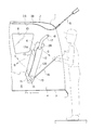
図1乃至図3は、車室内の様子を明らかにした自動車の概略断面図である。これらの図における符号Frは、自動車の前進方向を示し、この前進方向Frに直交する、図1乃至図3の紙面に対して垂直な方向が車幅方向である。図4にはこの車幅方向を符号Wで示してある(図5においても同様)。本明細書における「前」又は「後」なる文言は、自動車の前進方向Frを基準とした前後を意味する。   FIG. 1 to FIG. 3 are schematic cross-sectional views of an automobile in which the interior of the vehicle interior is clarified. Reference numeral Fr in these figures indicates the forward direction of the automobile, and the direction perpendicular to the paper surface of FIGS. 1 to 3 perpendicular to the forward direction Fr is the vehicle width direction. In FIG. 4, the vehicle width direction is indicated by a symbol W (the same applies to FIG. 5). In this specification, the terms “front” or “rear” mean front and rear with respect to the forward direction Fr of the automobile.

図1に示した自動車の車体1、すなわちそのメインボデーは、それ自体周知のように、車体1の上部を構成するルーフパネル2と、車室Rの床面を構成するフロアパネル3と、車室Rの車幅方向各側部を構成するサイドパネル4などの各種のパネルから構成されており、図1乃至図3には一方のサイドパネル4だけが示されている。ルーフパネル2は、互いに一体に固着されたインナパネル2Aとアウタパネル2Bより成る。かかる車体1の後部開口にはバックドア5が配置され、このバックドア5は図1に矢印A,Bで示した方向に回動開閉可能に車体1に支持されている。さらに、車体1の各サイドパネル4に形成されたドア開口7には、車体1に回動開閉可能に支持されたサイドドア9が配置され、その後方の窓開口8には窓ガラス10が配置されている。また、サイドパネル4の車室内側の面は図示していない内装材によって覆われ、ルーフパネル2のインナパネル2Aの車室内側の面は図示していない天井材で覆われている。   The vehicle body 1 shown in FIG. 1, that is, its main body, as is known per se, is a roof panel 2 that forms the upper part of the vehicle body 1, a floor panel 3 that forms the floor surface of the passenger compartment R, It is comprised from various panels, such as the side panel 4 which comprises each side part of the vehicle width direction of the room | chamber R, and only the one side panel 4 is shown by FIG. The roof panel 2 includes an inner panel 2A and an outer panel 2B that are integrally fixed to each other. A back door 5 is disposed at the rear opening of the vehicle body 1, and the back door 5 is supported by the vehicle body 1 so as to be rotatable and openable in directions indicated by arrows A and B in FIG. Further, a side door 9 supported by the vehicle body 1 so as to be capable of opening and closing is disposed in the door opening 7 formed in each side panel 4 of the vehicle body 1, and a window glass 10 is disposed in the rear window opening 8. Has been. Further, the surface of the side panel 4 on the vehicle interior side is covered with an interior material (not shown), and the surface of the inner panel 2A of the roof panel 2 on the vehicle interior side is covered with a ceiling material (not shown).

車室R内には、フロントシートより成る座席20と、このフロントシートよりも後方に配置されたリヤシートより成る座席11が配置され、この座席11は、図1に示すように、他の座席20と同じく、着座者の背部を支えるシートバック12と、着座者の尻部を支えるシートクッション13と、シートバック12の上部に装着されていて、着座者の頭部を支えるヘッドレスト6とを有している。図4に示すように、本例の座席11には、2つのヘッドレスト6が設けられている。また、図1には座席11に着座した着座者Pを二点鎖線で簡略化して示してある。   In the passenger compartment R, a seat 20 made of a front seat and a seat 11 made of a rear seat arranged behind the front seat are arranged. As shown in FIG. Similarly, the seat back 12 that supports the back of the seat occupant, the seat cushion 13 that supports the back of the seat occupant, and the headrest 6 that is mounted on the top of the seat back 12 and supports the head of the seat occupant. ing. As shown in FIG. 4, two headrests 6 are provided in the seat 11 of this example. Further, FIG. 1 shows a seated person P seated on the seat 11 in a simplified manner with a two-dot chain line.

図1は、シートクッション13とシートバック12が共にその使用位置を占めた状態を示しており、このときシートクッション13はほぼ水平な姿勢を保ち、シートバック12はシートクッション13に対してほぼ垂直に立ち上がった姿勢を占めている。このように、シートバック12とシートクッション13が使用位置にある状態で、図1に示すように、着座者Pが座席11に着座することができる。   FIG. 1 shows a state in which the seat cushion 13 and the seat back 12 both occupy the use position. At this time, the seat cushion 13 maintains a substantially horizontal posture, and the seat back 12 is substantially perpendicular to the seat cushion 13. Occupy standing up. In this way, the seated person P can sit on the seat 11 as shown in FIG. 1 with the seat back 12 and the seat cushion 13 in the use position.

シートバック12が使用位置を占めたときに下部となるシートバック部分の車幅方向各側部には、そのシートバックフレーム(図5参照)に固定されたヒンジピン15がそれぞれ設けられている。またシートクッション13の車幅方向各側部には、そのクッションフレーム(図示せず)に固着されたブラケット14がそれぞれ設けられ、その各ブラケット14に形成された各孔が各ヒンジピン15にそれぞれ相対回転可能に嵌合している。   A hinge pin 15 fixed to the seat back frame (see FIG. 5) is provided on each side in the vehicle width direction of the seat back portion which is the lower portion when the seat back 12 occupies the use position. Each side portion of the seat cushion 13 in the vehicle width direction is provided with a bracket 14 fixed to the cushion frame (not shown), and the holes formed in the bracket 14 are respectively relative to the hinge pins 15. It is fitted so that it can rotate.

一方、図4にも示すように、シートバック12の車幅方向各側部の上部には、シートアーム17の一端部がそれぞれ固定され、その各シートアームの他端部は、枢ピン18を介して車体1の各サイドパネル4にそれぞれ回動可能に連結されている。   On the other hand, as shown in FIG. 4, one end portion of the seat arm 17 is fixed to the upper portion of each side portion in the vehicle width direction of the seat back 12, and the other end portion of each seat arm has a pivot pin 18. Via each of the side panels 4 of the vehicle body 1 via a via.

シートクッション13とシートバック12が図1に示した使用位置にあるとき、シートバック12に設けられた図示していないロック部材と、車体1に固定された図示していないストライカとが互いに係合し、同じくシートクッション13に設けられた図示していないロック部材と、車体1に固定された図示していないストライカが互いに係合する。これによってシートバック12とシートクッション13は、それぞれ図1に示した使用位置にロックされ、これによってシートクッション13は着座者Pの尻部を支え、シートバック12は着座者Pの背部を支えることができる。   When the seat cushion 13 and the seat back 12 are in the use position shown in FIG. 1, a lock member (not shown) provided on the seat back 12 and a striker (not shown) fixed to the vehicle body 1 are engaged with each other. Similarly, a lock member (not shown) provided on the seat cushion 13 and a striker (not shown) fixed to the vehicle body 1 are engaged with each other. As a result, the seat back 12 and the seat cushion 13 are locked in the use positions shown in FIG. 1, respectively, so that the seat cushion 13 supports the buttocks of the seated person P and the seat back 12 supports the back of the seated person P. Can do.

シートクッション13に設けられた上述のロック部材を、車体1に固定されたストライカから外して、シートクッション13に対するロックを解除すると、そのシートクッション13は、ヒンジピン15のまわりに設けられた図示していないスパイラルスプリングの作用によって、シートバック12のヒンジピン15のまわりに、図1に矢印Cで示した方向に回動し、図2に示したように、使用位置にあるシートバック12に重なった位置を占める。このときのシートクッション13の位置が、その非使用位置である。   When the lock member provided on the seat cushion 13 is removed from the striker fixed to the vehicle body 1 and the lock on the seat cushion 13 is released, the seat cushion 13 is provided around the hinge pin 15. 1 is rotated around the hinge pin 15 of the seat back 12 in the direction indicated by the arrow C in FIG. 1, and overlaps with the seat back 12 in the use position as shown in FIG. Occupy. The position of the seat cushion 13 at this time is the non-use position.

さらに、シートバック12に設けられた上述のロック部材を、車体1に固定されたストライカから外して、シートバック12に対するロックを解除し、そのシートバック12を軽く前方に押すと、シートバック12と車体1との間に設けられた図示していないガスダンパステーの作用によって、シートバック12は、シートクッション13と共に、枢ピン18のまわりに、図2に矢印Eで示した前方に向けて回動し、図3に示すように車室Rの上部に持ち上がった位置を占める。このときのシートバック12の位置が、その非使用位置である。このとき、シートクッション13はシートバック12の上に重なって位置し、シートバック12に設けられた図示していないロック部材が、車体に固定された図示していないストライカに係合して、シートバック12が車体1に対してロックされ、該シートバック12がシートクッション13と共にその非使用位置に保持される。   Further, when the above-described locking member provided on the seat back 12 is removed from the striker fixed to the vehicle body 1, the lock on the seat back 12 is released, and the seat back 12 is lightly pushed forward, the seat back 12 By the action of a gas damper stay (not shown) provided between the vehicle body 1 and the seat cushion 12, the seat back 12 and the seat cushion 13 are rotated around the pivot pin 18 toward the front indicated by the arrow E in FIG. As shown in FIG. 3, it occupies a position raised above the passenger compartment R. The position of the seat back 12 at this time is the non-use position. At this time, the seat cushion 13 is positioned so as to overlap the seat back 12, and a lock member (not shown) provided on the seat back 12 is engaged with a striker (not shown) fixed to the vehicle body. The back 12 is locked with respect to the vehicle body 1, and the seat back 12 is held in the non-use position together with the seat cushion 13.

上述のように、座席11を車室Rの上部に格納するので、その座席11の下方に大きな空間を確保でき、この空間に荷物(図示せず)を効率よく収納することができる。上述したところと逆の操作によって、座席11を図1に示した使用位置にもたらして、その座席11を使用することができる。すなわち、シートクッション13と共に、車室上部の非使用位置に持ち上げられたシートバック12に対するロックを解除した上で、シートバック12を枢ピン18のまわりに図3に矢印Fで示した方向に回動させて図2に示した位置にもたらし、次いでシートクッション13をヒンジピン15のまわりに図2に矢印Dで示した方向に回動させて、図1に示した位置にもたらす。このようにして、シートバック12とシートクッション13は再び使用位置を占め、このときそのシートクッション13とシートバック12は、それぞれ前述のロック部材とストライカによって車体1に対してロックされる。   As described above, since the seat 11 is stored in the upper portion of the passenger compartment R, a large space can be secured below the seat 11, and luggage (not shown) can be efficiently stored in this space. By reverse operation as described above, the seat 11 can be brought to the use position shown in FIG. 1 and the seat 11 can be used. In other words, together with the seat cushion 13, the lock on the seat back 12 lifted to the non-use position at the upper part of the passenger compartment is released, and the seat back 12 is rotated around the pivot pin 18 in the direction indicated by the arrow F in FIG. 2 is moved to the position shown in FIG. 2, and then the seat cushion 13 is rotated around the hinge pin 15 in the direction shown by the arrow D in FIG. 2 to the position shown in FIG. Thus, the seat back 12 and the seat cushion 13 again occupy the use position, and at this time, the seat cushion 13 and the seat back 12 are locked to the vehicle body 1 by the above-described locking member and striker, respectively.

上述のように、本例の自動車は、車室R内に配置された座席11を具備し、その座席11は、着座者Pの背部を支えるシートバック12と、該着座者Pの尻部を支えるシートクッション13と、そのシートバック12に装着されていて、着座者Pの頭部を支えるヘッドレスト6を有し、シートクッション13は、着座者Pが着座できる使用位置と、シートバック12に重なった状態の非使用位置との間を回動可能にシートバック12に連結され、該シートバック12は、着座者Pの背部を支えることのできる使用位置と、該シートバック12にシートクッション13が重なった状態で、該シートクッション13と共に、車室Rの上部に持ち上がった状態の非使用位置との間を回動可能に車体1に支持されていて、該シートバック12が非使用位置にあるとき、シートクッション13はシートバック12の上に重なった状態で位置し、そのシートクッション13とシートバック12は、ほぼ水平姿勢を保つように構成されている。また、ヘッドレスト6は、シートバック12が使用位置にある状態で、図1に示した最も上方に持ち上がった最上位置と、図2に示した最も下方に下がった最下位置との間を移動可能にシートバック12に支持されている。これに関連する具体的構成は後に詳しく説明する。   As described above, the automobile of this example includes the seat 11 disposed in the passenger compartment R, and the seat 11 includes the seat back 12 that supports the back of the seated person P and the buttocks of the seated person P. A seat cushion 13 to be supported and a headrest 6 which is mounted on the seat back 12 and supports the head of the seated person P. The seat cushion 13 overlaps the seat back 12 and a use position where the seated person P can sit. The seat back 12 is connected to the seat back 12 so as to be able to rotate between a non-use position in the closed state, and the seat back 12 has a use position capable of supporting the back of the seated person P, and a seat cushion 13 on the seat back 12. In the overlapped state, the seat cushion 13 is supported by the vehicle body 1 so as to be rotatable between the seat cushion 13 and the non-use position lifted to the upper part of the passenger compartment R, and the seat back 12 is not used. When in the location, the seat cushion 13 is located in a state where it is superimposed on the seat back 12, the seat cushion 13 and the seat back 12 that is configured to maintain a substantially horizontal attitude. Further, the headrest 6 is movable between the uppermost position shown in FIG. 1 and the lowermost position shown in FIG. 2 with the seat back 12 in the use position. It is supported by the seat back 12. A specific configuration related to this will be described in detail later.

さらに、本例の自動車においては、図2に示したようにシートバック12とシートクッション13を折り畳んで、これらを図3に示した車室上部に持ち上げ、逆にそのシートバック12とシートクッション13を再び図2に示した位置に降ろすときの操作性を高める目的で、そのシートバック12に把手アーム16が設けられている。図1に示したように、着座者Pが座席11に着座したとき、その着座者Pの背部を支えるシートバック12の面をシートバック支え面12Aと称し、これとは反対側の面をシートバック背面12Bと称することにすると、把手アーム16は、このシートバック背面12Bの側に設けられている。しかも、シートバック12が図1に示した使用位置にあるときに下部となる把手アーム16の基端部に支持軸19が固定され、把手アーム16はこの支持軸19を介して、シートバック12のシートバックフレームに回動可能に連結されている。また、図4に示すように、把手アーム16の自由端21の側には、孔22が形成され、この孔22によって把手アーム16用の把手部が構成されている。   Further, in the automobile of this example, the seat back 12 and the seat cushion 13 are folded as shown in FIG. 2, and these are lifted to the upper part of the passenger compartment shown in FIG. 3, and conversely the seat back 12 and the seat cushion 13 A handle arm 16 is provided on the seat back 12 for the purpose of improving the operability when the door is lowered to the position shown in FIG. As shown in FIG. 1, when the seated person P is seated on the seat 11, the surface of the seat back 12 that supports the back of the seated person P is referred to as a seat back support surface 12A, and the surface on the opposite side is seated. When referred to as the back back surface 12B, the handle arm 16 is provided on the seat back back surface 12B side. Moreover, a support shaft 19 is fixed to the base end portion of the lower handle arm 16 when the seat back 12 is in the use position shown in FIG. 1, and the handle arm 16 is connected to the seat back 12 via the support shaft 19. The seat back frame is rotatably connected. As shown in FIG. 4, a hole 22 is formed on the free end 21 side of the handle arm 16, and a handle portion for the handle arm 16 is configured by the hole 22.

座席11に着座者Pが着座して、その座席11を使用しているとき、把手アーム16は、通常、図1に破線で示したようにシートバック背面12Bに沿って位置する格納位置に収められている。このとき、把手アーム16は、図示していないロック装置によって、その格納位置に保持されている。このロック装置としては、例えば、シートバック背面12Bに回動可能に支持されたロック爪を用いることができ、そのロック爪によって、格納位置にある把手アーム16を押えて、これをロックし、当該ロック爪を回動することによって、そのロック爪を把手アーム16から離して該把手アーム16に対するロックを解除することができる。   When a seated person P is seated on the seat 11 and is using the seat 11, the handle arm 16 is normally stored in a retracted position located along the seat back back surface 12B as indicated by a broken line in FIG. It has been. At this time, the handle arm 16 is held in its retracted position by a lock device (not shown). As this locking device, for example, a locking claw that is rotatably supported on the seat back back surface 12B can be used, and the lock arm 16 presses the handle arm 16 in the storage position to lock it, and By rotating the lock claw, the lock claw can be separated from the handle arm 16 and the lock on the handle arm 16 can be released.

シートバック12とシートクッション13を前述のように車室上部に持ち上げるときは、先ず図1に示したバックドア5を矢印A方向に回動させて、これを図2に示した開位置にもたらす。次いで、図2に二点鎖線で簡略化して示した操作者が、バックドア5を開くことにより開放された車体後部の開口から手を入れ、上述のロック爪を回動して把手アーム16のロックを解除した上で、把手アーム16の孔22(図4)に指を掛けて、該把手アーム16を、図1に矢印Gで示したように、その自由端21が後方に移動する向きに回動させ、その把手アーム16を図2に示した使用位置に回動させる。このとき、その把手アーム16は、シートバック12に設けられた図示していないストッパに当って、使用位置に保持される。把手アーム16が格納位置と使用位置の間の中間位置まで回動したときの様子を図1に二点鎖線で示してある。また、図4は、把手アーム16がこの中間位置まで回動したときの様子を示している。   When the seat back 12 and the seat cushion 13 are lifted to the upper part of the passenger compartment as described above, the back door 5 shown in FIG. 1 is first rotated in the direction of arrow A to bring it to the open position shown in FIG. . Next, the operator shown in a simplified manner with a two-dot chain line in FIG. 2 puts his hand through the opening at the rear of the vehicle body which is opened by opening the back door 5, and rotates the lock claw to move the handle arm 16. After releasing the lock, a finger is put on the hole 22 (FIG. 4) of the handle arm 16, and the handle arm 16 is moved in the direction in which the free end 21 moves backward as indicated by an arrow G in FIG. The handle arm 16 is rotated to the use position shown in FIG. At this time, the handle arm 16 hits a stopper (not shown) provided on the seat back 12 and is held at the use position. A state when the handle arm 16 is rotated to an intermediate position between the storage position and the use position is indicated by a two-dot chain line in FIG. FIG. 4 shows a state where the handle arm 16 is rotated to the intermediate position.

把手アーム16を使用位置にもたらし、前述のロック部材によるシートクッション13に対するロックを解除して、シートクッション13を図2に示した非使用位置に回動させると共に、シートバック12に対するロックを解除して、操作者は、その把手アーム16を掴んだまま、これを車体1の前方側に軽く押せば、前述のガスダンパステーの作用により、シートバック12は、シートクッション13と共に、矢印E方向に回動し、図3に示した非使用位置に持ち上げられる。引き続き、操作者は、把手アーム16を矢印H方向に回動させて、これを格納位置に収め、前述のロック爪を回動して把手アーム16を格納位置にロックする。逆の操作によって、シートバック12をシートクッション13と共に楽にその使用位置に回動させることができる。   The handle arm 16 is brought to the use position, the lock to the seat cushion 13 by the locking member is released, the seat cushion 13 is rotated to the non-use position shown in FIG. 2, and the lock to the seat back 12 is released. Then, if the operator holds the handle arm 16 and presses it lightly toward the front side of the vehicle body 1, the seat back 12 and the seat cushion 13 together with the seat cushion 13 are moved in the direction of the arrow E by the action of the gas damper stage. It rotates and is lifted to the non-use position shown in FIG. Subsequently, the operator rotates the handle arm 16 in the direction of arrow H, stores it in the storage position, and rotates the locking claw described above to lock the handle arm 16 in the storage position. By the reverse operation, the seat back 12 together with the seat cushion 13 can be easily rotated to the use position.

上述のように、シートバック12を使用位置と非使用位置との間で移動させるときに使用される把手アーム16は、シートバック背面12Bに沿って位置する格納位置と、その把手アーム16の自由端21がシートバック背面12Bから離間して位置する使用位置との間を回動できるように、シートバック12が使用位置にあるときに下部となる把手アーム16の基端部が、シートバック12に回動可能に連結されている。このように、本例の自動車は、使用位置と格納位置との間を回動可能にシートバック12に支持された把手アーム16を有しているので、操作者は、使用位置にある把手アーム16に手を掛けて楽にシートクッションとシートバックを車室上部に回動させ、或いはそのシートクッションとシートバックを楽に下方に回動させることができる。また、把手アーム16はシートバック背面12Bの側に設けられているので、図4に示すように把手アーム16を大型に構成しても、着座者の邪魔となることはない。このように把手アーム16のサイズを大きくすることにより、図2及び図3に示したように、操作者は楽な姿勢を保ったまま、その把手アーム16に手を掛けて、シートバック12とシートクッション13を回動させることができる。 As described above, the handle arm 16 used when the seat back 12 is moved between the use position and the non-use position includes the storage position positioned along the seat back back surface 12B and the free movement of the handle arm 16. The base end portion of the grip arm 16 serving as a lower portion when the seat back 12 is in the use position is configured so that the end 21 can be rotated between the use position positioned away from the seat back back surface 12B. It is connected to the pivotable. Thus, since the automobile of this example has the handle arm 16 supported by the seat back 12 so as to be rotatable between the use position and the storage position, the operator can use the handle arm in the use position. It is possible to easily turn the seat cushion and the seat back to the upper part of the passenger compartment by placing the hand on the seat 16, or to easily turn the seat cushion and the seat back downward. Further, since the handle arm 16 is provided on the seat back back surface 12B side, even if the handle arm 16 is configured to be large as shown in FIG. 4, it does not disturb the seated person. By increasing the size of the handle arm 16 in this manner, as shown in FIG. 2 and FIG. 3, the operator holds his / her grip arm 16 while maintaining a comfortable posture, and the seat back 12 and The seat cushion 13 can be rotated.

前述のように、ヘッドレスト6は、図1に示した最上位置と図2に示した最下位置との間を移動可能にシートバック12に支持されているので、着座者Pの体躯に合わせてヘッドレスト6の高さ位置を調整することができる。ところが、ヘッドレスト6を最上位置に持ち上げたまま、シートバック12を非使用位置に格納したとすると、シートバック12から大きく突出したヘッドレスト6が車室内の大きな空間を占めてしまうので、荷物収納空間が狭められてしまう。また、ルーフパネル2の形態によっては、ヘッドレスト6を最上位置に突出させたまま、シートバック12を非使用位置へと回動させたとき、そのヘッドレスト6がルーフパネル2の車室内側に設けられた天井材に干渉して、シートバック12を非使用位置に格納できなくなることも考えられる。そこで、操作者は、先ずヘッドレスト6を最下位置に押し下げ、次いでシートバック12をシートクッション13と共に非使用位置に回動させればよいが、シートバック12を格納する毎に、手操作によってヘッドレスト6を最下位置に押し下げることは煩わしい。   As described above, the headrest 6 is supported by the seat back 12 so as to be movable between the uppermost position shown in FIG. 1 and the lowermost position shown in FIG. The height position of the headrest 6 can be adjusted. However, if the seatback 12 is stored in the non-use position while the headrest 6 is lifted to the uppermost position, the headrest 6 that protrudes greatly from the seatback 12 occupies a large space in the passenger compartment, so that the luggage storage space is reduced. It will be narrowed. Further, depending on the form of the roof panel 2, when the seat back 12 is rotated to the non-use position with the headrest 6 protruding to the uppermost position, the headrest 6 is provided on the vehicle interior side of the roof panel 2. It is conceivable that the seat back 12 cannot be stored in the non-use position due to interference with the ceiling material. Therefore, the operator may first push down the headrest 6 to the lowest position, and then rotate the seat back 12 together with the seat cushion 13 to the non-use position, but each time the seat back 12 is stored, the headrest is manually operated. It is troublesome to push 6 down to the lowest position.

そこで、本例の自動車には、シートバック12が使用位置を占め、かつヘッドレスト6が最上位置にある状態で、把手アーム16を格納位置から使用位置へと回動させたとき、その回動に伴って、ヘッドレスト6が最上位置から最下位置へと移動するように、把手アーム16の回動に連動してヘッドレスト6を作動させる連動手段が設けられている。以下にこの連動手段の具体的構成を明らかにする。   Therefore, in the automobile of this example, when the handle arm 16 is rotated from the storage position to the use position in a state where the seat back 12 occupies the use position and the headrest 6 is at the uppermost position, the rotation is not performed. Accordingly, interlocking means for operating the headrest 6 in conjunction with the rotation of the handle arm 16 is provided so that the headrest 6 moves from the uppermost position to the lowermost position. The specific configuration of the interlocking means will be clarified below.

図5は、シートバック12のシートバックフレーム23の一部と、一方のヘッドレスト6と、把手アーム16と、連動手段とを示す斜視図である。ここに示したシートバックフレーム23は、上フレーム部材24と、下フレーム部材25と、これらのフレーム部材24,25の車幅方向各端部を一体に連結する端部連結部材31(図5には一方の端部連結部材のみを示す)と、上フレーム部材24と下フレーム部材25の車幅方向中間領域を一体に連結する一対の中間連結部材26と、これらの中間連結部材26に固定された架橋板27とから構成されている。かかるシートバックフレーム23と、図示していないクッション材と、そのクッション材を覆う図示していない表皮とによってシートバック12が構成される。   FIG. 5 is a perspective view showing a part of the seat back frame 23 of the seat back 12, one headrest 6, the handle arm 16, and the interlocking means. The seat back frame 23 shown here includes an upper frame member 24, a lower frame member 25, and end connection members 31 (see FIG. 5) that integrally connect the end portions of the frame members 24 and 25 in the vehicle width direction. Shows only one end connecting member), a pair of intermediate connecting members 26 that integrally connect the intermediate region in the vehicle width direction of the upper frame member 24 and the lower frame member 25, and these intermediate connecting members 26. And a cross-linked plate 27. The seat back 12 includes the seat back frame 23, a cushion material (not shown), and a skin (not shown) that covers the cushion material.

ここで、ヘッドレスト6は、図5及び図6に示すように、着座者の頭部を支えるヘッドレスト本体28と、その本体28から下方に突出する一対のステー29と、その両ステー29の下端に固定された係合部材41とを有している。かかるヘッドレスト6の各ステー29がシートバックフレーム23の上フレーム部材24に固定された筒状の一対のガイド部材30に摺動可能に嵌合している。係合部材41の機能については後述する。   Here, as shown in FIGS. 5 and 6, the headrest 6 has a headrest main body 28 that supports the head of the seated person, a pair of stays 29 protruding downward from the main body 28, and lower ends of both the stays 29. And a fixed engaging member 41. Each stay 29 of the headrest 6 is slidably fitted to a pair of cylindrical guide members 30 fixed to the upper frame member 24 of the seat back frame 23. The function of the engaging member 41 will be described later.

上述のヘッドレスト6を図5に矢印I,Jで示した方向に移動させることによって、そのヘッドレスト6を最上位置と最下位置の間を作動させることができる。このようにして、ヘッドレスト6を所望する高さ位置にもたらした後、図示していないロック装置によってヘッドレスト6をその位置に固定する。再び、そのロック装置のロックを解除することにより、ヘッドレスト6を上下方向に作動させることができる。   By moving the headrest 6 described above in the directions indicated by arrows I and J in FIG. 5, the headrest 6 can be operated between the uppermost position and the lowermost position. In this way, after the headrest 6 is brought to a desired height position, the headrest 6 is fixed to the position by a locking device (not shown). The headrest 6 can be operated in the up-down direction again by releasing the lock of the locking device.

一方、把手アーム16の基端部に固定された支持軸19は、図5に示すように、シートバックフレーム23の下フレーム部材25に固着された一対のブラケット32に回転可能に支持されている。支持軸19がブラケット32を介して、シートバック12に回転可能に支持されているのである。かかる支持軸19には、図6にも示すように、ピニオン33が固定され、このピニオン33は、作動部材34に固定されたラック35に噛み合っている。なお、図5及び図6においては、ピニオン33とラック35の歯を簡略化して示してある。   On the other hand, the support shaft 19 fixed to the proximal end portion of the handle arm 16 is rotatably supported by a pair of brackets 32 fixed to the lower frame member 25 of the seat back frame 23 as shown in FIG. . The support shaft 19 is rotatably supported by the seat back 12 via the bracket 32. As shown in FIG. 6, a pinion 33 is fixed to the support shaft 19, and the pinion 33 meshes with a rack 35 fixed to the operating member 34. 5 and 6, the teeth of the pinion 33 and the rack 35 are shown in a simplified manner.

ここに一例として示した作動部材34は、図6にも示すように、シートバックが図1に示した使用位置にあるとき、ほぼ上下方向に延びる垂直板36と、その垂直板36に一体に固定されていて、ほぼ水平方向に延びる水平板37とから構成されていて、垂直板36の下部に上述のラック35が固定されている。また、垂直板36には、その長手方向に長く延びたガイド孔38が形成され、その各ガイド孔38には、前述の架橋板26に固定されたガイドピン39が相対摺動可能に嵌合している。このようにして、作動部材34は、シートバックフレーム23の架橋板27に、矢印K,Lで示す方向に移動可能に支持されている。また、また、水平板37には、一対の切欠40が形成され、その各切欠40にヘッドレスト6のステー29がそれぞれ摺動可能に嵌合している。   As shown in FIG. 6, the actuating member 34 shown as an example here, when the seat back is in the use position shown in FIG. The rack 35 is composed of a horizontal plate 37 that is fixed and extends substantially in the horizontal direction, and the rack 35 is fixed to the lower portion of the vertical plate 36. The vertical plate 36 is formed with guide holes 38 extending in the longitudinal direction, and the guide pins 39 fixed to the bridge plate 26 are fitted in the guide holes 38 so as to be slidable relative to each other. is doing. In this way, the operating member 34 is supported by the bridge plate 27 of the seat back frame 23 so as to be movable in the directions indicated by the arrows K and L. Moreover, a pair of notches 40 are formed in the horizontal plate 37, and the stays 29 of the headrest 6 are slidably fitted in the notches 40, respectively.

図7乃至図9は、ヘッドレスト6と、作動部材34と、ラック35と、ピニオン33と、把手アーム16の動作を説明する図であって、使用位置を占めたシートバック12を仮想線で示した説明図である。図5及び図7は、把手アーム16が格納位置に収められ、しかもヘッドレスト6が最上位置に上昇したときの状態を示している。   FIGS. 7 to 9 are views for explaining the operations of the headrest 6, the operating member 34, the rack 35, the pinion 33, and the handle arm 16, and the seat back 12 that occupies the use position is indicated by a virtual line. FIG. 5 and 7 show a state where the handle arm 16 is stored in the storage position and the headrest 6 is raised to the uppermost position.

ここで、先にも説明したように、シートバック12を非使用位置に収めるには、先ず、ロック装置によるヘッドレスト6のロックを解除した後、格納位置にある把手アーム16を掴んで、これを支持軸19の中心軸線のまわりに図7に矢印Gで示した方向に回動させる。これにより、支持軸19と、その支持軸19に固定されたピニオン33も把手アーム16と同じ方向に回転する。把手アーム16の回動に伴って、ピニオン33がその把手アーム16と同じ方向に回転するのである。   Here, as described above, in order to place the seat back 12 in the non-use position, first, after unlocking the headrest 6 by the locking device, the grip arm 16 in the storage position is gripped, 7 is rotated around the central axis of the support shaft 19 in the direction indicated by the arrow G in FIG. As a result, the support shaft 19 and the pinion 33 fixed to the support shaft 19 also rotate in the same direction as the handle arm 16. As the handle arm 16 rotates, the pinion 33 rotates in the same direction as the handle arm 16.

上述のようにピニオン33が回転すると、これに噛み合ったラック35と、そのラック35が固定された作動部材34が、図7に矢印Kで示したように下方に移動する。このとき、図5に示した架橋部材27に固定されたガイドピン39が、作動部材34に形成された長孔より成るガイド孔38に相対摺動可能に嵌合しているので、作動部材34は、そのガイドピン39によって案内されながら、確実に矢印K方向に移動することができる。   When the pinion 33 rotates as described above, the rack 35 engaged with the pinion 33 and the operation member 34 to which the rack 35 is fixed move downward as indicated by an arrow K in FIG. At this time, the guide pin 39 fixed to the bridging member 27 shown in FIG. 5 is fitted in the guide hole 38 formed of a long hole formed in the operating member 34 so as to be slidable relative to the operating member 34. Can be reliably moved in the direction of the arrow K while being guided by the guide pins 39.

作動部材34が上述のように下降すると、その水平板37がヘッドレスト6のステー29の下端部に固定された係合部材41に係合して、その係合部材41を下方に押し下げる。これによって、ヘッドレスト6は、図7に矢印Iで示すように下方に移動する。このようにして、図8に示したように把手アーム16を使用位置まで回動させたとき、ヘッドレスト6は最下位置に至る。   When the operation member 34 is lowered as described above, the horizontal plate 37 engages with the engagement member 41 fixed to the lower end portion of the stay 29 of the headrest 6 and pushes the engagement member 41 downward. As a result, the headrest 6 moves downward as indicated by an arrow I in FIG. In this manner, when the handle arm 16 is rotated to the use position as shown in FIG. 8, the headrest 6 reaches the lowest position.

上述のように、ヘッドレスト6が最上位置にある状態で、把手アーム16を格納位置から使用位置へと回動させたとき、その回動に伴って、ヘッドレスト6が自動的にその最上位置から最下位置に移動するのである。このようにヘッドレスト6を最下位置に下降させた後、前述のようにシートクッション13と共にシートバック12を図3に示した非使用位置にもたらせば、車室内に大きな荷物収納空間を確保することができる。   As described above, when the handle arm 16 is rotated from the retracted position to the use position while the headrest 6 is at the uppermost position, the headrest 6 is automatically moved from the uppermost position to the uppermost position along with the rotation. It moves to the lower position. After the headrest 6 is lowered to the lowest position in this way, if the seat back 12 is brought into the non-use position shown in FIG. 3 together with the seat cushion 13 as described above, a large luggage storage space is secured in the vehicle interior. can do.

上述のように、本例の連動手段は、把手アーム16の回動に伴って回転するように支持軸19に固定されたピニオン33と、該ピニオン33に噛み合うラック35と、該ラック35が固定された作動部材34とを有し、該作動部材34は、把手アーム16を格納位置から使用位置へと回動させるのに伴って、ピニオン33が回転し、かつ該ピニオン33に噛み合ったラック35が作動したとき、最上位置にあったヘッドレスト16に係合して、該ヘッドレスト16を最下位置へ移動させるようにシートバック12に支持されている。   As described above, the interlocking means of this example includes the pinion 33 that is fixed to the support shaft 19 so as to rotate as the handle arm 16 rotates, the rack 35 that meshes with the pinion 33, and the rack 35 that is fixed. The operating member 34 has a rack 35 in which the pinion 33 rotates and meshes with the pinion 33 as the handle arm 16 is rotated from the retracted position to the operating position. Is operated by the seat back 12 so as to engage with the headrest 16 located at the uppermost position and move the headrest 16 to the lowermost position.

図8に示したようにヘッドレスト6を最下位置に押し込んだまま、非使用位置に収められていたシートバック12を使用位置に戻し、次いで把手アーム16を支持軸19の中心軸線まわりに矢印H方向に回動させると、ピニオン33が同じ方向に回転するので、ラック35と作動部材34は図8に矢印Lで示すように上方に作動する。これに対し、ヘッドレスト6は最下位置に留まる。このため、把手アーム16を図9に示した格納位置に収めたとき、作動部材34の水平板37とヘッドレスト6の係合部材41は、上下方向に大きく離間している。この状態で、ヘッドレスト6を図9に矢印Jで示すように上方に持ち上げれば、支障なくそのヘッドレスト6を図7に示した最上位置に移動させることができる。把手アーム16を格納位置に収めておき、ヘッドレスト6に対するロックを解除すれば、ヘッドレスト6を自由に昇降させることができ、任意の上下方向位置でそのヘッドレスト6をロックすることができるのである。   As shown in FIG. 8, with the headrest 6 pushed into the lowest position, the seat back 12 stored in the non-use position is returned to the use position, and then the handle arm 16 is moved to the arrow H around the central axis of the support shaft 19. As the pinion 33 is rotated in the same direction, the rack 35 and the operating member 34 operate upward as indicated by an arrow L in FIG. On the other hand, the headrest 6 remains at the lowest position. For this reason, when the handle arm 16 is stored in the retracted position shown in FIG. 9, the horizontal plate 37 of the operating member 34 and the engaging member 41 of the headrest 6 are greatly separated in the vertical direction. In this state, if the headrest 6 is lifted upward as shown by an arrow J in FIG. 9, the headrest 6 can be moved to the uppermost position shown in FIG. If the handle arm 16 is stored in the retracted position and the lock on the headrest 6 is released, the headrest 6 can be freely raised and lowered, and the headrest 6 can be locked at an arbitrary vertical position.

以上、一方のヘッドレスト6の具体的構成と、そのヘッドレストを昇降させるための構成を説明したが、他方のヘッドレストも同じく構成され、かつ全く同様の構成によって昇降される。   Although the specific configuration of one headrest 6 and the configuration for raising and lowering the headrest have been described above, the other headrest is also configured in the same manner and lifted up and down with the same configuration.

自動車の概略断面図であって、シートバックとシートクッションが使用位置にあるときの車室内の様子を示した図である。1 is a schematic cross-sectional view of an automobile, and is a view showing a state of a passenger compartment when a seat back and a seat cushion are in a use position. シートクッションをシートバックに重ねた非使用位置に回動させたときの様子を示す、図1と同様な概略断面図である。FIG. 2 is a schematic cross-sectional view similar to FIG. 1, illustrating a state when the seat cushion is rotated to a non-use position where the seat cushion is stacked on the seat back. シートバックを車室上部の非使用位置にもたらしたときの様子を示す、図1と同様な概略断面図である。FIG. 2 is a schematic cross-sectional view similar to FIG. 1, showing a state when the seat back is brought to a non-use position in the upper part of the passenger compartment. 座席を斜め後方から見た斜視図である。It is the perspective view which looked at the seat from diagonally backward. シートバックフレームと、ヘッドレストと、把手アームと、連動手段を示す斜視図である。It is a perspective view which shows a seat back frame, a headrest, a handle arm, and interlocking means. ヘッドレストと、把手アームと、作動部材の分解斜視図である。It is a disassembled perspective view of a headrest, a handle arm, and an operation member. 把手アームの回動に伴うヘッドレストの作動状態を示す説明図である。It is explanatory drawing which shows the operation state of the headrest accompanying rotation of a handle arm. 把手アームの回動に伴うヘッドレストの作動状態を示す説明図である。It is explanatory drawing which shows the operation state of the headrest accompanying rotation of a handle arm. 把手アームの回動に伴うヘッドレストの作動状態を示す説明図である。It is explanatory drawing which shows the operation state of the headrest accompanying rotation of a handle arm.

符号の説明Explanation of symbols

1 車体
6 ヘッドレスト
11 座席
12 シートバック
12A シートバック支え面
12B シートバック背面
13 シートクッション
16 把手アーム
19 支持軸
21 自由端
33 ピニオン
34 作動部材
35 ラック
P 着座者
DESCRIPTION OF SYMBOLS 1 Car body 6 Headrest 11 Seat 12 Seat back 12A Seat back support surface 12B Seat back back surface 13 Seat cushion 16 Handle arm 19 Support shaft 21 Free end 33 Pinion 34 Actuating member 35 Rack P Seated person

Claims (3)

着座者の背部を支えることのできる使用位置と非使用位置との間を移動可能に車体に支持されたシートバックと、該シートバックに装着されていて、着座者の頭部を支えるヘッドレストと、前記シートバックを使用位置と非使用位置との間を移動させるときに使用される把手アームとを有し、該把手アームは、使用位置と格納位置との間を回動可能に前記シートバックに支持され、前記ヘッドレストは、前記シートバックが使用位置にある状態で最も上方に持ち上がった最上位置と最も下方に下がった最下位置との間を移動可能にシートバックに支持され、前記シートバックが使用位置を占め、かつ前記ヘッドレストが最上位置にある状態で、前記把手アームを格納位置から使用位置へと回動させたとき、その回動に伴って、前記ヘッドレストが最上位置から最下位置へと移動するように、該把手アームの回動に連動してヘッドレストを作動させる連動手段が設けられている自動車。 A seat back that is supported by the vehicle body so as to be movable between a use position and a non-use position that can support the back of the seated person, a headrest that is attached to the seat back and supports the head of the seated person, A grip arm used when the seat back is moved between the use position and the non-use position, and the handle arm can be pivoted between the use position and the storage position on the seat back. and supported, pre Symbol headrest, the seat back is supported movably seat back between a lowermost position most lowered downwardly most upwardly raised uppermost position in the position of use, the seat back When the handle arm is rotated from the retracted position to the used position while the headrest is at the uppermost position, the headless So they move to the lowermost position from the uppermost position, vehicle interlocking means is provided for operating the headrest in conjunction with rotation of 該把 hand arm. 車室内に配置された座席を具備し、該座席は、着座者の背部を支えるシートバックと、該着座者の尻部を支えるシートクッションと、前記シートバックに装着されていて、着座者の頭部を支えるヘッドレストとを有し、前記シートクッションは、着座者が着座できる使用位置と、前記シートバックに重なった状態の非使用位置との間を回動可能にシートバックに連結され、該シートバックは、着座者の背部を支えることのできる使用位置と、該シートバックにシートクッションが重なった状態で、該シートクッションと共に、車室の上部に持ち上がった状態の非使用位置との間を回動可能に車体に支持されていて、該シートバックが非使用位置にあるとき、前記シートクッションはシートバックの上に重なった状態で位置しており、前記ヘッドレストは、前記シートバックが使用位置にある状態で最も上方に持ち上がった最上位置と最も下方に下がった最下位置との間を移動可能にシートバックに支持されていて、着座者の背部を支えるシートバック支え面と反対側のシートバック背面の側に、該シートバックを使用位置と非使用位置との間で移動させるときに使用される把手アームが設けられ、該把手アームは、シートバック背面に沿って位置する格納位置と、該把手アームの自由端がシートバック背面から離間して位置する使用位置との間を回動できるように、前記シートバックが使用位置にあるときに下部となる把手アームの基端部が、シートバックに回動可能に連結され、前記シートバックが使用位置を占め、かつ前記ヘッドレストが最上位置にある状態で、前記把手アームを格納位置から使用位置へと回動させたとき、その回動に伴って、前記ヘッドレストが最上位置から最下位置へと移動するように、該把手アームの回動に連動してヘッドレストを作動させる連動手段が設けられている自動車。 A seat disposed in the passenger compartment, the seat being a seat back that supports the back of the seated person, a seat cushion that supports the buttocks of the seated person, and the seat back, The seat cushion is connected to the seat back so as to be rotatable between a use position where a seated person can sit and a non-use position in a state where the seat cushion overlaps the seat back. The back rotates between the use position where the back of the seated person can be supported and the non-use position where the seat cushion overlaps with the seat back and is lifted to the upper part of the passenger compartment together with the seat cushion. When the seat back is in a non-use position and is movably supported by the vehicle body, the seat cushion is positioned overlying the seat back, and the head The rest is supported by the seat back so as to be movable between an uppermost position lifted upward and a lowermost position lowered downward while the seatback is in the use position, and supports the back of the seated person A grip arm used when the seat back is moved between the use position and the non-use position is provided on the side of the back of the seat back opposite to the seat back support surface. When the seat back is in the use position, the lower portion becomes the lower position so that the free end of the handle arm can be rotated between the storage position located along With the base end of the handle arm pivotably connected to the seat back, the seat back occupies the use position, and the head rest is in the uppermost position. When the handle is rotated from the storage position to the use position, the headrest is operated in conjunction with the rotation of the handle arm so that the headrest moves from the uppermost position to the lowermost position along with the rotation. Automobiles that are provided with interlocking means. 前記把手アームの基端部に支持軸が固定され、該支持軸はシートバックに回転可能に支持されていて、前記連動手段は、前記把手アームの回動に伴って回転するように前記支持軸に固定されたピニオンと、該ピニオンに噛み合うラックと、該ラックが固定された作動部材とを有し、該作動部材は、前記把手アームを格納位置から使用位置へと回動させるのに伴って、前記ピニオンが回転し、かつ該ピニオンに噛み合ったラックが作動したとき、最上位置にあった前記ヘッドレストに係合して、該ヘッドレストを最下位置へ移動させるようにシートバックに支持されている請求項1又は2に記載の自動車。 A support shaft is fixed to a base end portion of the handle arm, the support shaft is rotatably supported by a seat back, and the interlocking means rotates so as to rotate as the handle arm rotates. A pinion fixed to the pinion, a rack meshing with the pinion, and an operation member to which the rack is fixed, and the operation member rotates the handle arm from the retracted position to the use position. When the pinion rotates and the rack engaged with the pinion is operated, the headrest is supported by the seat back so as to engage with the headrest located at the uppermost position and move the headrest to the lowermost position. The automobile according to claim 1 or 2.
JP2007310293A 2007-11-30 2007-11-30 Automobile Active JP4968534B2 (en)

Priority Applications (1)

Application Number Priority Date Filing Date Title
JP2007310293A JP4968534B2 (en) 2007-11-30 2007-11-30 Automobile

Applications Claiming Priority (1)

Application Number Priority Date Filing Date Title
JP2007310293A JP4968534B2 (en) 2007-11-30 2007-11-30 Automobile

Publications (2)

Publication Number Publication Date
JP2009132287A JP2009132287A (en) 2009-06-18
JP4968534B2 true JP4968534B2 (en) 2012-07-04

Family

ID=40864621

Family Applications (1)

Application Number Title Priority Date Filing Date
JP2007310293A Active JP4968534B2 (en) 2007-11-30 2007-11-30 Automobile

Country Status (1)

Country Link
JP (1) JP4968534B2 (en)

Family Cites Families (5)

* Cited by examiner, † Cited by third party
Publication number Priority date Publication date Assignee Title
JPS53140224U (en) * 1977-04-11 1978-11-06
JPS6224584Y2 (en) * 1980-12-10 1987-06-23
US6073986A (en) * 1997-03-14 2000-06-13 Magna Interior Systems, Inc. Easily handled movable vehicle seat assembly
JP2000025504A (en) * 1998-07-13 2000-01-25 Nissan Motor Co Ltd Automotive seat headrest structure
JP2007302141A (en) * 2006-05-12 2007-11-22 Toyota Motor Corp Retractable seat device for vehicles

Also Published As

Publication number Publication date
JP2009132287A (en) 2009-06-18

Similar Documents

Publication Publication Date Title
JP4447515B2 (en) Control lever arrangement structure for vehicle seat
CN101357603B (en) Car
JP4190566B2 (en) Car
JP4790686B2 (en) Car
JP4190567B2 (en) Car
JP2008544790A (en) Open car headrest device
JP3992897B2 (en) Underfloor storage seat structure
JP4968534B2 (en) Automobile
JP2003118449A (en) Vehicle seat
JP4790673B2 (en) Car
JP2003118441A (en) Vehicle seat
JP2009269546A (en) Automobile
JP4947497B2 (en) Automobile
JP2003118451A (en) Vehicle seat
JP2008037237A (en) Automobile
JP5428182B2 (en) Car seat storage structure
JP4569386B2 (en) Vehicle seat storage structure
JP7099301B2 (en) Vehicle seat
JP4887852B2 (en) Auto body structure
JP2008006989A (en) Automobile
JP4353965B2 (en) Car
JP2005041378A (en) Vehicle seat device
JP2009241768A (en) Seat structure for vehicle
JP2003118452A (en) Vehicle seat
JP4978568B2 (en) Automobile

Legal Events

Date Code Title Description
A977 Report on retrieval

Free format text: JAPANESE INTERMEDIATE CODE: A971007

Effective date: 20110929

A131 Notification of reasons for refusal

Free format text: JAPANESE INTERMEDIATE CODE: A131

Effective date: 20111007

A521 Written amendment

Free format text: JAPANESE INTERMEDIATE CODE: A523

Effective date: 20111205

A711 Notification of change in applicant

Free format text: JAPANESE INTERMEDIATE CODE: A711

Effective date: 20111207

A521 Written amendment

Free format text: JAPANESE INTERMEDIATE CODE: A821

Effective date: 20111207

TRDD Decision of grant or rejection written
A01 Written decision to grant a patent or to grant a registration (utility model)

Free format text: JAPANESE INTERMEDIATE CODE: A01

Effective date: 20120308

A01 Written decision to grant a patent or to grant a registration (utility model)

Free format text: JAPANESE INTERMEDIATE CODE: A01

A61 First payment of annual fees (during grant procedure)

Free format text: JAPANESE INTERMEDIATE CODE: A61

Effective date: 20120321

FPAY Renewal fee payment (event date is renewal date of database)

Free format text: PAYMENT UNTIL: 20150413

Year of fee payment: 3

R151 Written notification of patent or utility model registration

Ref document number: 4968534

Country of ref document: JP

Free format text: JAPANESE INTERMEDIATE CODE: R151

FPAY Renewal fee payment (event date is renewal date of database)

Free format text: PAYMENT UNTIL: 20150413

Year of fee payment: 3