JP4966610B2 - Information processing system, emergency power-off method for information processing system - Google Patents
Information processing system, emergency power-off method for information processing system Download PDFInfo
- Publication number
- JP4966610B2 JP4966610B2 JP2006231852A JP2006231852A JP4966610B2 JP 4966610 B2 JP4966610 B2 JP 4966610B2 JP 2006231852 A JP2006231852 A JP 2006231852A JP 2006231852 A JP2006231852 A JP 2006231852A JP 4966610 B2 JP4966610 B2 JP 4966610B2
- Authority
- JP
- Japan
- Prior art keywords
- uninterruptible power
- notification
- information processing
- processing system
- power
- Prior art date
- Legal status (The legal status is an assumption and is not a legal conclusion. Google has not performed a legal analysis and makes no representation as to the accuracy of the status listed.)
- Active
Links
Images


Landscapes
- Power Sources (AREA)
Description
本発明は情報処理システムの緊急時電源断方式と方法に関し、特にUPS(無停止電源装置)を備えた情報処理システムの緊急時電源断方式と方法に関する。 The present invention relates to an emergency power-off method and method for an information processing system, and more particularly to an emergency power-off method and method for an information processing system equipped with a UPS (non-stop power supply device).
従来の、EPO(Emergency Power Off=緊急時電源断)機能を備えた電源制御方式が特許文献1に示されている。この電源制御方式は、本体装置に緊急時に電源を切断するスイッチ手段を設け、本体装置の電源制御部はこのスイッチ手段によって本体装置の電源が切断されたことを検出して複数の周辺装置に電源切断指令を送出し、各周辺装置の電源も同時に切断する。
A conventional power supply control system having an EPO (Emergency Power Off = Emergency Power Off) function is disclosed in
一方最近の情報処理システムでは、システムの一部に、EMU(拡張記憶装置)等の様に無停止電源を必要とする装置を含むシステムがあり、この様なシステムでは、EMUはUPSからAC電源を受けるが、設備費用等の理由により他の装置はそれぞれの電源装置が分電盤からAC電源を受けている。 On the other hand, in recent information processing systems, there is a system that includes a device that requires a non-disruptive power source, such as an EMU (Extended Storage Device), as part of the system. However, due to equipment costs and the like, each of the other power supply devices receives AC power from the distribution board.
この情報処理システムに従来のEPO機能付きの電源制御方式を採用した場合のシステム構成を図3に示す。 FIG. 3 shows a system configuration when a conventional power control method with an EPO function is adopted in this information processing system.
図3を参照すると、CPU10のEPOスイッチ101からの通知を受け、分電盤70に設けたリレー701によりAC切断を行う機能のほか、UPS50からEMU30に供給されている無停止電源も切断する必要があり、UPS50に外付けでリレー80等のハードウェアを設けることになる。
Referring to FIG. 3, in addition to the function of receiving the notification from the
また、上記情報処理システムには、システムの診断制御や状態監視のためSVP40(サービスプロセッサ)が設けられている。SVP40とEMU30間やSVP40とCPU10間は、診断制御等を行うためのインタフェースとしてバス100で接続されている。EMU30とUPS50の間は、EMU30がUPS50の状態を検知するための制御インタフェースケーブル105’が張られている。
The information processing system is provided with an SVP 40 (service processor) for system diagnostic control and status monitoring. The
しかしながら、従来のEPO機能を持つ電源制御方式においては、次のような課題がある。第1の課題は、UPSを使用している情報処理システムに適用すると、UPS側にリレー等の大掛かりなハードウェアを具備する必要があるということである。 However, the power supply control method having the conventional EPO function has the following problems. The first problem is that when applied to an information processing system using a UPS, it is necessary to provide a large-scale hardware such as a relay on the UPS side.
第2の課題は、UPSを使用している情報処理システムに適用すると、UPS側のリレーが駆動されると一方的に、無停止電源受電装置(EMU等)への給電が断たれるために、無停止電源受電装置の中で電源断シーケンスを守ることができず、電子部品の電気的な破壊を招くことがあるということである。 The second problem is that, when applied to an information processing system using a UPS, when a UPS-side relay is driven, power supply to a non-stop power receiving device (such as an EMU) is cut off. This means that the power-off sequence cannot be maintained in the non-stop power receiving device, and the electronic components may be electrically destroyed.
本発明の目的は前記課題を解決した、情報処理システムの緊急時電源断方式と方法を提供することにある。 An object of the present invention is to provide an emergency power-off method and method for an information processing system that solves the above-described problems.
本発明の第1の情報処理システムの緊急時電源断方式は、無停止電源を供給するUPS装置と前記UPS装置から無停止電源を受電する装置を含む情報処理システムの緊急時電源断方式であって、前記情報処理システムに緊急時電源断スイッチがオンになりEPO状態になったことを通知する手段を備え、前記無停止電源を受電する装置に前記EPO状態の通知を受け前記通知を前記UPS装置に転送する手段とクローズ処理を行い通常のオフシーケンスで動作電源をオフにする手段を備え、前記UPS装置に前記転送された通知を受信し所定時間経過後にAC電源出力を断つ手段を備える。 The emergency power-off method of the first information processing system of the present invention is an emergency power-off method of an information processing system including a UPS device that supplies non-stop power and a device that receives non-stop power from the UPS device. Means for notifying the information processing system that the emergency power-off switch has been turned on and has entered the EPO state, and the device receiving the non-stop power supply receives the notification of the EPO state and sends the notification to the UPS. Means for transferring to the apparatus and means for turning off the operating power in a normal off sequence, and means for receiving the transferred notification to the UPS apparatus and cutting off the AC power output after a predetermined time.
本発明の第2の情報処理システムの緊急時電源断方式は、情報処理システムの緊急時電源断方式であって、前記情報処理システムには、本体側の装置と、前記本体側の装置とインタフェースを持つサービスプロセッサと、周辺装置と、無停止電源を供給するUPS装置を含み、前記本体側の装置や周辺装置の内の少なくとも1台が前記UPS装置から無停止電源を受電する装置であり、前記本体側の装置の1台に、緊急時電源断スイッチと、前記緊急時電源断スイッチがオンになると分電盤にAC電源の切断動作開始を伝達し、EPO状態を前記サービスプロセッサに通知する手段を備え、前記サービスプロセッサに、前記インタフェースを監視しEPO状態になったことを検出するEPO状態監視手段と、前記検出を受け、EPO状態を通知する手段を備え、前記無停止電源を受電する装置に、前記EPO状態の通知を受け通知を前記UPS装置に転送する手段と、クローズ処理を行い通常のオフシーケンスで動作電源をオフにする手段を備え、前記UPS装置に、前記転送された通知を受信し所定時間経過後にAC電源出力を断つ手段を備える。 The emergency power-off method of the second information processing system of the present invention is an emergency power-off method of the information processing system, and the information processing system includes a main body side device, the main body side device and an interface. Including a service processor, a peripheral device, and a UPS device for supplying non-stop power, wherein at least one of the main body side device and the peripheral device receives non-stop power from the UPS device, When the emergency power-off switch and the emergency power-off switch are turned on, the AC power supply disconnection operation start is transmitted to the distribution board, and the EPO state is notified to the service processor. Means for monitoring the interface and detecting that the service processor is in an EPO state; and receiving the detection and passing the EPO state to the service processor. Means for receiving the notification of the EPO state and transferring the notification to the UPS device, and means for performing a closing process and turning off the operating power in a normal off sequence. And the UPS device includes means for receiving the transferred notification and cutting off the AC power output after a predetermined time has elapsed.
本発明の第3の情報処理システムの緊急時電源断方式は、前記第2の情報処理システムの緊急時電源断方式であって、前記サービスプロセッサの前記EPOを通知する手段が、通知先記憶部を参照し、前記無停止電源を受電する装置に、EPOを通知する様にした。 The emergency power-off method of the third information processing system of the present invention is the emergency power-off method of the second information processing system, and the means for notifying the EPO of the service processor is a notification destination storage unit The EPO is notified to the device that receives the non-stop power supply.
本発明の第4の情報処理システムの緊急時電源断方式は、前記第2の情報処理システムの緊急時電源断方式であって、前記緊急時電源断スイッチを備える前記本体側の装置を中央処理装置とする。 The emergency power-off method of the fourth information processing system of the present invention is the emergency power-off method of the second information processing system, and the apparatus on the main body side provided with the emergency power-off switch is centrally processed. A device.
本発明の第5の情報処理システムの緊急時電源断方式は、前記第2の情報処理システムの緊急時電源断方式であって、前記無停止電源を受電する装置を揮発性メモリを用いた拡張記憶装置とする。 The emergency power-off method of the fifth information processing system of the present invention is the emergency power-off method of the second information processing system, and the device that receives the non-stop power supply is expanded using a volatile memory. A storage device is assumed.
本発明の第1の情報処理システムの緊急時電源断方法は、無停止電源を供給するUPS装置と前記UPS装置から無停止電源を受電する装置を含む情報処理システムの緊急時電源断方法であって、前記情報処理システムに緊急時電源断スイッチがオンになりEPO状態になったことを通知する手順を備え、前記無停止電源を受電する装置に前記EPO状態の通知を受け前記通知を前記UPS装置に転送する手順と、クローズ処理を行い通常のオフシーケンスで動作電源をオフにする手順を備え、前記UPS装置に前記転送された通知を受信し所定時間経過後にAC電源出力を断つ手順を備える。 An emergency power-off method for an information processing system according to the present invention is an emergency power-off method for an information processing system including a UPS device that supplies non-stop power and a device that receives non-stop power from the UPS device. And a procedure for notifying the information processing system that the emergency power-off switch is turned on to enter the EPO state, and the device receiving the non-stop power supply receives the notification of the EPO state and sends the notification to the UPS. A procedure for transferring to the device, a procedure for performing a close process and turning off the operating power in a normal off sequence, and a procedure for receiving the transferred notification to the UPS device and cutting off the AC power output after a predetermined time has elapsed. .
本発明の第2の情報処理システムの緊急時電源断方法は、本体側の装置と、前記本体側の装置とインタフェースを持つサービスプロセッサと、周辺装置と、無停止電源を供給するUPS装置を含み、前記本体側の装置や周辺装置の内の少なくとも1台が前記UPS装置から無停止電源を受電する装置である情報処理システムの緊急時電源断方法であって、前記本体側の装置の一つが緊急時電源断スイッチと、前記スイッチがオンになると、分電盤にAC電源の切断動作開始を伝達し、EPO状態を前記サービスプロセッサに通知する手順を有し、前記サービスプロセッサが、前記インタフェースを監視しEPO状態になったことを検出するEPO状態監視手順と、前記検出を受けEPO状態を通知する手順を有し、前記無停止電源を受電する装置が、前記EPO状態の通知を受け、通知を前記UPS装置に転送する手順と、自装置のクローズ処理を行い通常のオフシーケンスで動作電源をオフにする手順を有し、前記UPS装置が、前記転送された通知を受信し所定時間経過後にAC電源出力を断つ手順を有する。 The emergency power-off method of the second information processing system according to the present invention includes a main body side device, a service processor having an interface with the main body side device, a peripheral device, and a UPS device for supplying non-stop power. An emergency information power-off method for an information processing system in which at least one of the main body side devices and peripheral devices receives non-stop power from the UPS device, wherein one of the main body side devices includes: An emergency power-off switch, and a procedure for transmitting an AC power-off operation start to a distribution board when the switch is turned on, and notifying the service processor of an EPO state. It has an EPO state monitoring procedure for monitoring and detecting the EPO state, and a procedure for receiving the detection and notifying the EPO state, and receiving the non-stop power supply Receiving a notification of the EPO state, transferring the notification to the UPS device, and performing a close process of the own device and turning off the operating power in a normal off sequence, It has a procedure of receiving the transferred notification and cutting off the AC power output after a predetermined time has elapsed.
本発明の第3の情報処理システムの緊急時電源断方法は、前記第2の情報処理システムの緊急時電源断方法であって、前記サービスプロセッサの前記EPOを通知する手順を、通知先記憶部を参照し、前記無停止電源を受電する装置にEPOを通知する手順とする。 An emergency power-off method of the third information processing system according to the present invention is an emergency power-off method of the second information processing system, and a procedure for notifying the EPO of the service processor is a notification destination storage unit. And a procedure for notifying the device that receives the non-stop power supply of EPO.
本発明の第4の情報処理システムの緊急時電源断方法は、前記第2の情報処理システムの緊急時電源断方法であって、前記緊急時電源断スイッチを備える前記本体側の装置を中央処理装置とする。 An emergency power-off method of the fourth information processing system according to the present invention is an emergency power-off method of the second information processing system, and the apparatus on the main body side including the emergency power-off switch is centrally processed. A device.
本発明の第5の情報処理システムの緊急時電源断方法は、前記第2の情報処理システムの緊急時電源断方法であって、前記無停止電源を受電する装置を揮発性メモリを用いた拡張記憶装置とする。 An emergency power-off method for an information processing system according to a fifth aspect of the present invention is an emergency power-off method for the second information processing system, wherein a device that receives the non-stop power supply is expanded using a volatile memory. A storage device is assumed.
本発明は、SVP、UPS、及びUPSからの無停止電源を受電している装置の既存のHWを流用することで、EPO時のUPS出力電源の切断やそれに伴う処理を実現することにより、UPSを含む情報処理システムに用いられても外付けで大掛かりなハードウェアの設備が不要になるという効果を持つ。 The present invention uses the existing HW of the device receiving the non-stop power supply from the SVP, UPS, and UPS, thereby realizing the UPS output power supply disconnection during EPO and the processing associated therewith. Even if it is used in an information processing system including a large amount of hardware, there is an effect that a large external hardware facility is unnecessary.
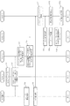
次に、本発明を実施するための最良の形態について図面を参照して詳細に説明する。図1は本発明の緊急時電源断方式を含む情報処理システムのブロック図である。図1を参照すると、本情報処理システムは、本体側装置として、CPU1(中央処理装置)とIOP2(入出力処理装置)とEMU3(拡張記憶装置)とSVP(サービスプロセッサ)を含み、周辺装置としてディスク記憶装置6−1、6−2を含み、更にEMU3は無停止電源を受電する装置であり、これ用のUPS5(無停止電源装置)も備える。 Next, the best mode for carrying out the present invention will be described in detail with reference to the drawings. FIG. 1 is a block diagram of an information processing system including an emergency power-off system according to the present invention. Referring to FIG. 1, the information processing system includes a CPU 1 (central processing unit), an IOP 2 (input / output processing unit), an EMU 3 (extended storage unit), and an SVP (service processor) as main unit side devices. The disk storage devices 6-1 and 6-2 are included, and the EMU 3 is a device that receives a non-stop power supply, and also includes a UPS 5 (non-stop power supply device).
CPU1には、EPOスイッチ11(緊急時電源断スイッチ)が実装されている。本実施形態ではEPOスイッチ11をCPU1に実装しているが、単独でEPO(緊急時電源断)機能を持つ装置があってもよく、情報処理システムとしての実装場所には拘らない。
The
大型汎用コンピュータでは診断制御やシステムの状態監視、或いはシステムのログ記録を行う目的で専用のSVP(サービスプロセッサ)を備えていることが多い。SVP4は、バス103によりCPU1、IOP2の本体側の各装置と接続されている。
Large general-purpose computers often have a dedicated SVP (service processor) for diagnostic control, system status monitoring, or system log recording. The
EPOスイッチ11が操作されオンになるとその旨(EPO状態)がバス103を介してSVP4に通知される。SVP4はバス103を監視し、EPO状態になったことを検出するEPO状態監視手段41を持つ。EPO状態監視手段41は、バス103を通じ所定回数以上EPO状態通知が行われたことをソフトウェア的に検出することで実現される。
When the EPO switch 11 is operated and turned on, the fact (EPO state) is notified to the
EMU3は、UPS5より無停止のAC電源を受けている。汎用大型コンピュータのEMU3は主記憶とディスク記憶装置6−1、6−2の中間に位置するために、記憶素子には主記憶と同じ高速の揮発性メモリ素子が用いられるが、アーキテクチャ上は不揮発性であることも要求されるので停電時の対策としてUPS5を通じて電源を受けている。
The EMU 3 receives a non-stop AC power supply from the UPS 5. Since the
SVP4は、情報処理システムでUPS5からAC電源を受電している装置の識別情報(通信アドレス)を付属する通知先記憶部43に記憶している。この通知先記憶部43にはEMU3が記憶されており、EPO通知手段42がEPO状態監視手段41から、システムがEPO状態になったことを通知されると、通知先記憶部43を参照し、EMU3に制御インタフェース106を介して、その旨を通知する。
The
EPO通知手段42はそのための手段であるが、SVP4から他装置への通信は多くのケースは汎用的なLAN(Local Area Network)カードによるネットワーク制御で行われるために、この通知はネットワーク上に特定の通信コードを定義し、そのコードをソフトウェアで発生することで実現する他の実施例もある。
The EPO notification means 42 is a means for this, but since communication from the
EMU3は制御インタフェース106を介して情報処理システムがEPO状態になったことをEPO通知受信手段31によって知る。前記他の実施例ではEPO通知受信手段31も、ネットワーク上に定義された前述の特定のコードをソフトウェア的に検出することで実現される。
The EMU 3 knows through the
今般の汎用コンピュータでは、自装置の電源をオフする際に、システムデータ等の保護をし、また電子部品を電気的な破壊から守るために、電源断のシーケンスを制御することが一般的である。例えば受電コンポーネントを同一の電源オフ/オンのタイミングを取るもの同士でセグメント化し、セグメントA〜セグメントDの各セグメントにそれぞれ専用の電源を割り当て、各電源のオフ/オンする順番をコントロールすることで実現している。ここで電源といっているのは、AC電源を入力として必要な動作用電源(主としてDC)を出力する装置のことで、EMU3に組み込まれている。
In general-purpose computers, it is common to control the power-off sequence in order to protect system data, etc., and to protect electronic components from electrical damage when turning off the power of its own device. . For example, it can be realized by segmenting power receiving components with the same power off / on timing, assigning a dedicated power source to each segment A to D, and controlling the order in which each power source is turned off / on is doing. The term “power source” as used herein refers to a device that outputs an operation power source (mainly DC) using an AC power source as an input, and is incorporated in the
この際にセグメントAにシステム制御上コアになるような情報があり、この情報を不揮発性メモリ(フラッシュメモリ等)に吐き出すまで電源を落としてはいけないようなケースでは、不揮発性メモリーに情報を吐き出すために必要充分な時間=Tを計算しておき、セグメントAの電源断が起動されてから、実際に電源をオフするまでの時間=Tを確保するようにソフトウェアや専用HWでコントロールしている。 At this time, in the case where the segment A has information that becomes a core for system control and the power cannot be turned off until the information is discharged to the nonvolatile memory (flash memory or the like), the information is discharged to the nonvolatile memory. Necessary and sufficient time = T is calculated, and control is performed by software or a dedicated HW so as to secure time = T from when the segment A power is turned off until the power is actually turned off. .
EMU3の自装置クローズ手段33は、こういった既存の電源断及び不揮発性メモリへの退避制御の仕掛けを起動する手段である。EMU3のEPO通知転送手段32は、EPO通知受信手段31で受信した内容を制御インタフェース105を介してUPS5に送信する手段である。
The
制御インタフェース105は汎用的なLANカードによるネットワーク接続でもよいし、単なる接点信号でのやりとりでもよい。例えば、レベルHigh=EPO状態/レベルLow=非EPO状態のように定義することで実現される。またこの制御インタフェース105は従来からEMU3側でUPS5の状態を検出するためにも必要なインタフェースである。従って、制御インタフェース105としてケーブル内の信号定義が本発明で新たに追加される程度であり、全体の金物量が増加する訳ではない。
The control interface 105 may be a network connection using a general-purpose LAN card, or may be a simple contact signal exchange. For example, it is realized by defining as Level High = EPO state / Level Low = non-EPO state. The control interface 105 is an interface necessary for detecting the state of the
EPO通知受信手段51は、制御インタフェース105が接点信号で定義される実施例では、この信号の立ち上がりエッジを検出し、その後定量的に同一LEVELとなっているかを確認することで実現される。こういったフィルター制御については一般的な事柄であるので詳細は言明しない。制御インタフェース105がLANネットワークでインタフェースが組まれている場合には、ソフトウェアでの検出となる。 In the embodiment in which the control interface 105 is defined by a contact signal, the EPO notification receiving means 51 is realized by detecting the rising edge of this signal and then confirming quantitatively the same LEVEL. Since such filter control is a general matter, details are not stated. When the control interface 105 is an LAN network interface, software detection is performed.
UPS5はEMU3に無停止のAC電源を給電しているが、短絡等の不具合を検出した場合には電源の供給を停止する電源供給断回路52を備えている。UPS5において、内部の短絡検出回路(図示せず)の出力にEPO通知受信手段51の出力がORされており、EPO通知受信手段51によってシステムがEPO状態となったことを検出した際に、電源供給断回路52を起動する。
The
次に、本発明を実施するための最良の形態の動作について図面を参照して説明する。図2は本発明の実施形態の動作を示したフローチャートである。図2を参照すると、EPOスイッチ11が操作されオンになると(ステップS1)、バス103を介してSVP4にEPO状態オンを示す通知コマンドが所定回数以上繰り返し通知され、また同時にEPOスイッチオン出力(レベル信号)がマシン室の分電盤7に伝送される(ステップS2)。
Next, the operation of the best mode for carrying out the present invention will be described with reference to the drawings. FIG. 2 is a flowchart showing the operation of the embodiment of the present invention. Referring to FIG. 2, when the EPO switch 11 is operated and turned on (step S1), a notification command indicating that the EPO state is turned on is repeatedly notified to the
分電盤7ではリレー71の駆動が開始される(ステップS3)。
In the
SVP4ではEPO状態監視手段41が、EPO状態通知コマンドの受信回数が所定値以上となり、情報処理システムがEPO状態になったことを検出し(ステップS4)、EPO通知手段42が通知先記憶部43を参照し、EMU3に制御インタフェース106を介しその旨を通知する(ステップS5)。
In
一方、分電盤7では、駆動開始より所定時間経つとリレー71がブレークし分電盤7からCPU1、IOP2、UPS5、ディスク記憶装置6−1、6−2の各装置への電源供給(例えばAC電源供給)は断たれる(ステップS6)。UPS5では、分電盤7からのAC電源断と同時に、バッテリからの電力供給が働きこれより作成されたAC電源をEMU3に給電し続ける(ステップS7)。
On the other hand, in the
EMU3ではEPO信号をEPO通知受信手段31が検出すると、EPO通知転送手段32がUPS5に制御インタフェース105を介してEPO状態を転送する(ステップS8)。次に、自装置クローズ手段33を使ってシステム情報等を不揮発性メモリ(フラッシュメモリ等)に吐き出し(ステップS9)、また電子部品の破壊がないように電源オフのシーケンスを守りながら動作電源をオフにする(ステップS10)。
In the
UPS5では、前記EPO状態が転送されるとEPO通知受信手段51によって情報処理装置システムがEPO状態になったことを検知し、電源供給断回路52の起動を指示する(ステップS11)。この際に、EMU3内の自装置クローズ処理に掛かる時間を電源供給断回路52を起動する際の時定数として扱い、この時定数経過後に、EMU3へのAC電源供給を断つ(ステップS12)。
In the
以上の実施形態の説明では、SVP4は前記通知先記憶部43を有し、EPO通知手段42がシステムがEPO状態になったことを通知されると、通知先記憶部43を参照し、EMU3にその旨を通知する例を説明したが、SVP4が前記通知先記憶部43を持たず、またEPO通知手段42がシステムがEPO状態になったことを通知されると、接続されている全装置にその旨を一斉に同報通知し、EMU3がこれを受けて、通知の転送やクローズ処理、動作電源オフシーケンスを行う実施例もある。
In the description of the above embodiment, the
本実施形態では、EPOスイッチ状態を監視しオン検出する手段や、EMUへの通知手段を実現するためのベースとなるハードウェアとしては既存のSVP4やバス103や制御インタフェース106の伝送メディアを利用し、EMU3からUPS5へのEPO状態通知は、両装置間の既存のインタフェースメデイアを利用することで実現し、UPSの出力を断つ手段そのものとしては、既存の電源供給断回路を利用している。
In this embodiment, existing SVP4,
従って、インタフェースメディアにおける信号線や、通知コマンド送信ソフトウェアや監視し検出するソフトウェアや既存回路の起動制御等を追加することで本発明が実施できるので、本発明の情報処理システムの緊急時電源断方式がUPSを含む情報処理システムに用いられても外付けで大掛かりなハードウェアの設備は不要である。 Accordingly, the present invention can be implemented by adding signal lines in the interface media, notification command transmission software, monitoring and detection software, activation control of existing circuits, etc., so the emergency power-off method of the information processing system of the present invention Even if it is used in an information processing system including a UPS, a large external hardware facility is not required.
本実施形態によれば、UPSに接続され、無停止電源を受電する装置内の電源断シーケンスを保証しながらEPO状態に遷移しているので、前記装置内の電気的な部品破壊等を招くことが無くなり、災害等からの復旧時に速やかに前記装置を再立ち上げすることができる。 According to the present embodiment, the state is changed to the EPO state while guaranteeing the power-off sequence in the device that is connected to the UPS and receives the non-stop power supply. And the apparatus can be restarted promptly upon recovery from a disaster or the like.
1 CPU
11 EPOスイッチ
2 IOP
3 EMU
31 EPO通知受信手段
32 EPO通知転送手段
33 自装置クローズ手段
4 SVP
41 EPO状態監視手段
42 EPO通知手段
43 通知先記憶部
5 UPS
51 EPO通知受信手段
52 電源供給断回路
6−1、6−2 ディスク記憶装置
7 分電盤
71 リレー
103 バス
105、106 制御インタフェース
1 CPU
11
3 EMU
31 EPO notification receiving means 32 EPO notification transferring means 33 Self-device closing means 4 SVP
41 EPO state monitoring means 42 EPO notification means 43 Notification
51 EPO
Claims (10)
前記情報処理システムは、緊急時電源断スイッチがオンになると、分電盤にAC電源の切断動作開始を伝達し、緊急時電源断(EPO)状態になったことを示す通知を、前記無停電電源受電装置に送信するEPO通知手段を備え、
前記無停電電源受電装置は、前記通知を受け、前記通知を前記UPS装置に転送する手段と、前記通知を受け、自装置のクローズ処理を行い所定のオフシーケンスで動作電源をオフにする手段を備え、
前記UPS装置は、前記無停電電源受電装置から前記転送された通知を受信し所定時間経過後に前記無停電電源受電装置への無停電電源の出力を断つ手段を備える情報処理システム。 An information processing system including a UPS device that supplies uninterruptible power and an uninterruptible power receiving device that is a device that receives uninterrupted power from the UPS device
When the emergency power-off switch is turned on, the information processing system transmits an AC power-off operation start to the distribution board, and notifies the uninterruptible power supply that the emergency power-off (EPO) state has been established. EPO notification means for transmitting to the power receiving device,
The uninterruptible power supply receiving device receives the notification, means for transferring the notification to the UPS device, and means for receiving the notification , performing a closing process of the own device, and turning off the operating power in a predetermined off sequence. Prepared,
The UPS device is an information processing system comprising means for receiving the transferred notification from the uninterruptible power receiving device and cutting off the output of the uninterruptible power supply to the uninterruptible power receiving device after a predetermined time has elapsed.
前記本体側装置または前記周辺装置の内の少なくとも1台が前記UPS装置から無停止電源を受電する装置である無停電電源受電装置であり、
前記本体側装置の1台に、緊急時電源断スイッチと、前記緊急時電源断スイッチがオンになると分電盤にAC電源の切断動作開始を伝達し、緊急時電源断(EPO)状態を前記サービスプロセッサに通知する手段を備え、
前記サービスプロセッサは、前記インタフェースを監視しEPO状態になったことを検出するEPO状態監視手段と、前記検出を受け、EPO状態になったことを示す通知を、前記無停電電源受電装置に送信するEPO通知手段を備え、
前記無停電電源受電装置は、前記通知を受け、前記通知を前記UPS装置に転送する手段と、前記通知を受け、自装置のクローズ処理を行い所定のオフシーケンスで動作電源をオフにする手段を備え、
前記UPS装置は、前記無停電電源受電装置から前記転送された通知を受信し所定時間経過後に前記無停電電源受電装置への無停電電源の出力を断つ手段を備える情報処理システム。 A main body side device, a service processor having an interface with the main body side device, a peripheral device, and a UPS device for supplying a non-stop power supply,
An uninterruptible power supply receiving device in which at least one of the main body side device or the peripheral device receives uninterruptible power from the UPS device,
When the emergency power cut-off switch and the emergency power cut-off switch are turned on, an AC power cut-off operation start is transmitted to one of the main body side devices, and the emergency power-off (EPO) state is Means for notifying the service processor;
The service processor transmits to the uninterruptible power receiving device an EPO state monitoring unit that monitors the interface and detects that the EPO state has been detected, and a notification indicating that the service has entered the EPO state. EPO notification means
The uninterruptible power supply receiving device receives the notification, means for transferring the notification to the UPS device, and means for receiving the notification , performing a closing process of the own device, and turning off the operating power in a predetermined off sequence. Prepared,
The UPS device is an information processing system comprising means for receiving the transferred notification from the uninterruptible power receiving device and cutting off the output of the uninterruptible power supply to the uninterruptible power receiving device after a predetermined time has elapsed.
前記UPS装置は、前記時間Tを経過後に前記無停電電源受電装置への無停電電源の出力を断つ、請求項2に記載の情報処理システム。 The uninterruptible power receiving device is segmented for each component having the same timing to turn off the operating power until the information included in the segment including information necessary for controlling the information processing system is output to the nonvolatile memory Controlling the off sequence so that the operating power is turned off after a time T required for
The information processing system according to claim 2, wherein the UPS device cuts off the output of the uninterruptible power supply to the uninterruptible power receiving device after the time T has elapsed.
前記情報処理システムは、緊急時電源断スイッチがオンになり緊急時電源断(EPO)状態になったことを示す通知を、前記無停電電源受電装置に送信し、
前記無停電電源受電装置は、前記通知を受け、前記通知を前記UPS装置に転送し、前記通知を受け、自装置のクローズ処理を行い所定のオフシーケンスで動作電源をオフにし、
前記UPS装置は、前記無停電電源受電装置から前記転送された通知を受信し所定時間経過後に前記無停電電源受電装置への無停電電源の出力を断つ、情報処理システムの緊急時電源断方法。 An emergency power-off method for an information processing system including a UPS device that supplies uninterruptible power and an uninterruptible power supply that is a device that receives uninterruptible power from the UPS device,
The information processing system transmits a notification indicating that an emergency power-off switch is turned on and an emergency power-off (EPO) state is established, to the uninterruptible power supply device,
The uninterruptible power supply device receives the notification, transfers the notification to the UPS device, receives the notification , performs a close process of the own device, and turns off the operating power in a predetermined off sequence,
An emergency power-off method for an information processing system, wherein the UPS device receives the transferred notification from the uninterruptible power supply device and cuts off the output of the uninterruptible power supply to the uninterruptible power supply device after a lapse of a predetermined time.
前記本体側装置または前記周辺装置の内の少なくとも1台が前記UPS装置から無停止電源を受電する装置である無停電電源受電装置である情報処理システムの緊急時電源断方法であって、
前記本体側装置の一つは、緊急時電源断スイッチがオンになると、分電盤にAC電源の切断動作開始を伝達し、緊急時電源断(EPO)状態を前記サービスプロセッサに通知する手順を有し、
前記サービスプロセッサは、前記インタフェースを監視しEPO状態になったことを検出し、前記検出を受けEPO状態になったことを示す通知を、前記無停電電源受電装置に送信し、
前記無停電電源受電装置は、前記通知を受け、前記通知を前記UPS装置に転送し、前記通知を受け、自装置のクローズ処理を行い所定のオフシーケンスで動作電源をオフにし、
前記UPS装置は、前記無停電電源受電装置から前記転送された通知を受信し所定時間経過後に前記無停電電源受電装置への無停電電源の出力を断つ、情報処理システムの緊急時電源断方法。 A main body side device, a service processor having an interface with the main body side device, a peripheral device, and a UPS device for supplying a non-stop power supply,
An emergency power-off method for an information processing system, which is an uninterruptible power receiving device, in which at least one of the main body side device or the peripheral device receives uninterruptible power from the UPS device,
When the emergency power-off switch is turned on, one of the main body-side devices transmits a procedure for notifying the service processor of an emergency power-off (EPO) state by transmitting an AC power-off operation start to the distribution board. Have
The service processor monitors the interface to detect that it has entered the EPO state, and transmits a notification indicating that the detection has entered the EPO state to the uninterruptible power supply device.
The uninterruptible power supply device receives the notification, transfers the notification to the UPS device, receives the notification , performs a close process of the own device, and turns off the operating power in a predetermined off sequence,
An emergency power-off method for an information processing system, wherein the UPS device receives the transferred notification from the uninterruptible power supply device and cuts off the output of the uninterruptible power supply to the uninterruptible power supply device after a lapse of a predetermined time.
前記UPS装置は、前記時間Tを経過後に前記無停電電源受電装置への無停電電源の出力を断つ、請求項7記載の情報処理システムの緊急時電源断方法。 The uninterruptible power receiving device is segmented for each component having the same timing to turn off the operating power until the information included in the segment including information necessary for controlling the information processing system is output to the nonvolatile memory Controlling the off sequence so that the operating power is turned off after a time T required for
8. The emergency power-off method for an information processing system according to claim 7, wherein the UPS device cuts off the output of the uninterruptible power source to the uninterruptible power receiving device after the time T has elapsed.
Priority Applications (1)
| Application Number | Priority Date | Filing Date | Title |
|---|---|---|---|
| JP2006231852A JP4966610B2 (en) | 2006-08-29 | 2006-08-29 | Information processing system, emergency power-off method for information processing system |
Applications Claiming Priority (1)
| Application Number | Priority Date | Filing Date | Title |
|---|---|---|---|
| JP2006231852A JP4966610B2 (en) | 2006-08-29 | 2006-08-29 | Information processing system, emergency power-off method for information processing system |
Publications (2)
| Publication Number | Publication Date |
|---|---|
| JP2008059029A JP2008059029A (en) | 2008-03-13 |
| JP4966610B2 true JP4966610B2 (en) | 2012-07-04 |
Family
ID=39241734
Family Applications (1)
| Application Number | Title | Priority Date | Filing Date |
|---|---|---|---|
| JP2006231852A Active JP4966610B2 (en) | 2006-08-29 | 2006-08-29 | Information processing system, emergency power-off method for information processing system |
Country Status (1)
| Country | Link |
|---|---|
| JP (1) | JP4966610B2 (en) |
Families Citing this family (2)
| Publication number | Priority date | Publication date | Assignee | Title |
|---|---|---|---|---|
| KR100858341B1 (en) | 2008-04-24 | 2008-09-16 | (주)재원엔지니어링 | Electric supply line structure for apartment house |
| JP2010016283A (en) * | 2008-07-07 | 2010-01-21 | Nuflare Technology Inc | Drawing device |
Family Cites Families (11)
| Publication number | Priority date | Publication date | Assignee | Title |
|---|---|---|---|---|
| JPS6197730A (en) * | 1984-10-17 | 1986-05-16 | Fujitsu Ltd | Power failure processing system for computer system |
| JPS62123517A (en) * | 1985-11-22 | 1987-06-04 | Panafacom Ltd | Control system for power supply |
| JPS62134725A (en) * | 1985-12-06 | 1987-06-17 | Nec Corp | Recognizing system for device constitution of computer system |
| JPS6349916A (en) * | 1986-08-20 | 1988-03-02 | Fujitsu Ltd | Detecting system for computer failure due to voltage abnormality |
| JPH0239311A (en) * | 1988-07-29 | 1990-02-08 | Fujitsu Ltd | Power supply control system |
| JPH0793058A (en) * | 1993-09-28 | 1995-04-07 | Fujitsu Ltd | Power source control unit for input/output device |
| JPH113150A (en) * | 1997-06-12 | 1999-01-06 | Meidensha Corp | Information processor |
| JP2000010667A (en) * | 1998-06-22 | 2000-01-14 | Kawamura Electric Inc | Power source controller |
| JP2000357059A (en) * | 1999-06-14 | 2000-12-26 | Toshiba Corp | Disk array device |
| JP2003174737A (en) * | 2001-12-06 | 2003-06-20 | Hitachi Ltd | Uninterruptive power supply unit |
| JP2006172276A (en) * | 2004-12-17 | 2006-06-29 | Hitachi Ltd | Uninterruptible power supply system and program |
-
2006
- 2006-08-29 JP JP2006231852A patent/JP4966610B2/en active Active
Also Published As
| Publication number | Publication date |
|---|---|
| JP2008059029A (en) | 2008-03-13 |
Similar Documents
| Publication | Publication Date | Title |
|---|---|---|
| KR20010062749A (en) | Remote power management system of information processing apparatus or the like | |
| US9026685B2 (en) | Memory module communication control | |
| US7275182B2 (en) | Method and apparatus for correlating UPS capacity to system power requirements | |
| JP6130520B2 (en) | MULTISYSTEM SYSTEM AND MULTISYSTEM SYSTEM MANAGEMENT METHOD | |
| US6438639B1 (en) | Computer system bus network providing concurrent communication and connection transition of peripheral devices | |
| JP2005192306A (en) | Uninterruptible power supply device, power supply control program, recording medium for power supply control program, and power supply control method | |
| JP4655718B2 (en) | Computer system and control method thereof | |
| JP4966610B2 (en) | Information processing system, emergency power-off method for information processing system | |
| CN115795568A (en) | Liquid cooling server liquid leakage protection method, device, equipment and storage medium | |
| CN102646176A (en) | Hard disk data protection system and protection method thereof | |
| JP5174093B2 (en) | Electronic device and control program thereof | |
| JP2000163164A (en) | Power source controller and no-break power unit | |
| JP6762032B2 (en) | Power receiving device and control method | |
| JP2007218453A (en) | Air conditioner controller, air conditioner control method, and recording medium recording air conditioner control program | |
| JP4068277B2 (en) | Hardware system | |
| JP2014164488A (en) | Control device, control method, and control program | |
| JP4987450B2 (en) | Image forming apparatus | |
| JP2017033321A (en) | Power supply control system, power supply control device, and power supply control method | |
| JP2008299749A (en) | Power supply control circuit, function expansion unit, image forming apparatus, and power supply control method | |
| JP2008129969A (en) | Power supply backup system and electronic equipment provided with the same | |
| JP2008152316A (en) | Communication system, device, host, communication method, and program | |
| JP3107104B2 (en) | Standby redundancy method | |
| JPH07319574A (en) | Method and circuit for protecting device in abnormal temperature | |
| JP2003208245A (en) | Communication adapter connected to information processor and ups | |
| JP2006085497A (en) | Cooling method, cooling system, and cooling program |
Legal Events
| Date | Code | Title | Description |
|---|---|---|---|
| RD01 | Notification of change of attorney |
Free format text: JAPANESE INTERMEDIATE CODE: A7421 Effective date: 20080616 |
|
| A621 | Written request for application examination |
Free format text: JAPANESE INTERMEDIATE CODE: A621 Effective date: 20081020 |
|
| RD01 | Notification of change of attorney |
Free format text: JAPANESE INTERMEDIATE CODE: A7421 Effective date: 20090519 |
|
| A977 | Report on retrieval |
Free format text: JAPANESE INTERMEDIATE CODE: A971007 Effective date: 20100602 |
|
| A131 | Notification of reasons for refusal |
Free format text: JAPANESE INTERMEDIATE CODE: A131 Effective date: 20100615 |
|
| A521 | Written amendment |
Free format text: JAPANESE INTERMEDIATE CODE: A523 Effective date: 20100726 |
|
| A131 | Notification of reasons for refusal |
Free format text: JAPANESE INTERMEDIATE CODE: A131 Effective date: 20110510 |
|
| A521 | Written amendment |
Free format text: JAPANESE INTERMEDIATE CODE: A523 Effective date: 20110610 |
|
| RD01 | Notification of change of attorney |
Free format text: JAPANESE INTERMEDIATE CODE: A7421 Effective date: 20110712 |
|
| TRDD | Decision of grant or rejection written | ||
| A01 | Written decision to grant a patent or to grant a registration (utility model) |
Free format text: JAPANESE INTERMEDIATE CODE: A01 Effective date: 20120313 |
|
| A01 | Written decision to grant a patent or to grant a registration (utility model) |
Free format text: JAPANESE INTERMEDIATE CODE: A01 |
|
| A61 | First payment of annual fees (during grant procedure) |
Free format text: JAPANESE INTERMEDIATE CODE: A61 Effective date: 20120402 |
|
| R150 | Certificate of patent or registration of utility model |
Ref document number: 4966610 Country of ref document: JP Free format text: JAPANESE INTERMEDIATE CODE: R150 Free format text: JAPANESE INTERMEDIATE CODE: R150 |
|
| FPAY | Renewal fee payment (event date is renewal date of database) |
Free format text: PAYMENT UNTIL: 20150406 Year of fee payment: 3 |
|
| S111 | Request for change of ownership or part of ownership |
Free format text: JAPANESE INTERMEDIATE CODE: R313111 |
|
| R350 | Written notification of registration of transfer |
Free format text: JAPANESE INTERMEDIATE CODE: R350 |