JP4965911B2 - Inkjet recording apparatus and inkjet recording control method - Google Patents
Inkjet recording apparatus and inkjet recording control method Download PDFInfo
- Publication number
- JP4965911B2 JP4965911B2 JP2006179818A JP2006179818A JP4965911B2 JP 4965911 B2 JP4965911 B2 JP 4965911B2 JP 2006179818 A JP2006179818 A JP 2006179818A JP 2006179818 A JP2006179818 A JP 2006179818A JP 4965911 B2 JP4965911 B2 JP 4965911B2
- Authority
- JP
- Japan
- Prior art keywords
- recording
- ink
- port array
- ejection
- discharge
- Prior art date
- Legal status (The legal status is an assumption and is not a legal conclusion. Google has not performed a legal analysis and makes no representation as to the accuracy of the status listed.)
- Expired - Fee Related
Links
- 238000000034 method Methods 0.000 title claims description 20
- 238000003491 array Methods 0.000 claims description 35
- 239000000976 ink Substances 0.000 description 439
- 238000006073 displacement reaction Methods 0.000 description 44
- 238000010586 diagram Methods 0.000 description 25
- 230000003111 delayed effect Effects 0.000 description 12
- 238000004519 manufacturing process Methods 0.000 description 12
- 230000006866 deterioration Effects 0.000 description 6
- 238000011084 recovery Methods 0.000 description 6
- 230000000694 effects Effects 0.000 description 5
- 239000000758 substrate Substances 0.000 description 3
- 238000007599 discharging Methods 0.000 description 2
- 230000003287 optical effect Effects 0.000 description 2
- WBMKMLWMIQUJDP-STHHAXOLSA-N (4R,4aS,7aR,12bS)-4a,9-dihydroxy-3-prop-2-ynyl-2,4,5,6,7a,13-hexahydro-1H-4,12-methanobenzofuro[3,2-e]isoquinolin-7-one hydrochloride Chemical compound Cl.Oc1ccc2C[C@H]3N(CC#C)CC[C@@]45[C@@H](Oc1c24)C(=O)CC[C@@]35O WBMKMLWMIQUJDP-STHHAXOLSA-N 0.000 description 1
- 241000396922 Pontia daplidice Species 0.000 description 1
- 230000002457 bidirectional effect Effects 0.000 description 1
- 238000004140 cleaning Methods 0.000 description 1
- 239000003086 colorant Substances 0.000 description 1
- 239000000470 constituent Substances 0.000 description 1
- 230000007547 defect Effects 0.000 description 1
- 238000010438 heat treatment Methods 0.000 description 1
- 238000003860 storage Methods 0.000 description 1
Images


Classifications
-
- B—PERFORMING OPERATIONS; TRANSPORTING
- B41—PRINTING; LINING MACHINES; TYPEWRITERS; STAMPS
- B41J—TYPEWRITERS; SELECTIVE PRINTING MECHANISMS, i.e. MECHANISMS PRINTING OTHERWISE THAN FROM A FORME; CORRECTION OF TYPOGRAPHICAL ERRORS
- B41J19/00—Character- or line-spacing mechanisms
- B41J19/14—Character- or line-spacing mechanisms with means for effecting line or character spacing in either direction
- B41J19/142—Character- or line-spacing mechanisms with means for effecting line or character spacing in either direction with a reciprocating print head printing in both directions across the paper width
- B41J19/145—Dot misalignment correction
Description
本発明は、インクジェット記録装置およびその記録制御方法に関し、特に記録位置ずれを調整するための構成および方法に関する。 The present invention relates to an ink jet recording apparatus and a recording control method thereof, and more particularly to a configuration and a method for adjusting a recording position shift.
インクジェット記録装置は、記録速度の向上のため、複数の記録素子を集積配列してなる記録ヘッドとして、インク吐出部としてのインク吐出口及び液路を複数集積したものを用い、さらにカラー対応として、複数個の前記記録ヘッドを備えたものが一般的である。 The ink jet recording apparatus uses a recording head in which a plurality of recording elements are integrated and arranged in order to improve recording speed. Generally, a plurality of the recording heads are provided.
図1は前記記録ヘッドで記録紙面上を記録していく際のインクジェットプリンタ部の構成を示したものである。同図において、101はインクカートリッジである。これらはブラック、シアン、マゼンタ、イエローの4色のインクがそれぞれ詰め込まれたインクタンクと、102の同一の記録ヘッドより構成されている。この記録ヘッド上に配列する吐出口の様子をZ方向から示したものが図2であり、201、202は記録ヘッド102上に複数配列された吐出口である。再び図1に戻ると、103は紙送りローラで104の拍車とともに記録媒体Pを抑えながら図の矢印の方向に回転し、記録媒体PをY方向の副走査方向に随時送っていく。また105は給紙ローラであり記録媒体Pの給紙を行うとともに、103、104と同様、記録媒体Pを抑える役割も果たす。106は4つのインクカートリッジを支持し、記録とともにこれらを移動させるキャリッジである。キャリッジは、記録を行っていないとき、あるいは記録ヘッドの回復作業などを行うときには図の点線で示した位置のホームポジション(h)に待機する。
FIG. 1 shows a configuration of an ink jet printer section when recording on a recording paper surface by the recording head. In the figure,
記録開始前、図の位置(ホームポジション)にあるキャリッジ106は、記録開始命令がくると、X方向の主走査方向に移動しながら、記録ヘッド102上の複数の吐出口201、202からインクを吐出して記録を行う。ホームポジションとは反対側に位置する記録媒体端部まで画像を形成するための記録が終了するとキャリッジは元のホームポジションに戻り、再びX方向への記録を繰り返す片方向記録を行う。また、高速印刷を行うために、+X方向の往路方向と−X方向の復路方向の両方から記録を行う双方向記録を行う。
Prior to the start of printing, the carriage 106 at the position shown in the figure (home position) receives ink from a plurality of
このとき、上記4色の各吐出口列から吐出されるドットの記録位置にズレや往路方向と復路方向の両方から吐出されるドットの記録位置のズレが発生する場合がある。また、記録ヘッドの取り付け精度、製造バラツキが原因で吐出口列の主走査方向に対する傾きを引き起こす。こうした不具合が存在したままだと、記録媒体に対して傾斜したドットが印刷されてしまう。これを調整するために、ドットの記録位置調整(レジ調整)を行うことが知られている。 At this time, there may be a shift in the recording position of the dots ejected from each of the four color ejection port arrays and a shift in the recording position of the dots ejected from both the forward direction and the backward direction. Further, the ejection head array is inclined with respect to the main scanning direction due to the mounting accuracy of the recording head and manufacturing variations. If these defects remain, dots that are inclined with respect to the recording medium are printed. In order to adjust this, it is known to perform dot recording position adjustment (registration adjustment).
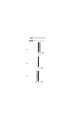
図2は、図1で説明した4色のインクの内ブラックインクを吐出するインク吐出口列Aとシアンインクを吐出するインク吐出口列Bの各1列のインク吐出口列で構成された2つの記録ヘッドを示す。記録ヘッドはインク吐出口数L=12個で、インク吐出口の間隔が1/600インチにより記録画素密度が600dpiになるように構成されている。インク吐出口201はインク吐出口列Aのインク吐出口n12を示し、同様にインク吐出口202はインク吐出口列Bのインク吐出口n1を示す。また、記録ヘッドからの吐出量は、1滴あたり約2plのインク滴が吐出可能なように構成されており、このインク滴を安定して吐出するための吐出周波数は30kHzで吐出速度は、約20m/秒となっている。この記録ヘッドを搭載したキャリッジの主走査方向への速度は、主走査方向にインク滴を1200dpi間隔に記録すると約25インチ/秒となる。
FIG. 2 is a diagram showing an example of two ink discharge port arrays each including an ink discharge port array A for discharging black ink and an ink discharge port array B for discharging cyan ink among the four color inks described in FIG. Two recording heads are shown. The recording head is configured so that the number of ink ejection ports is L = 12, the interval between the ink ejection ports is 1/600 inch, and the recording pixel density is 600 dpi. The
上記記録ヘッド102を用いて、2列の吐出口列間の記録位置のズレを調整する。図34は、図2のインク吐出口列Aとインク吐出口列Bの往路方向から吐出されるドットの2列間の記録位置のズレを調整するためのチェックパターンであり、図4は、図34の0〜+2を拡大したものである。インク吐出口列Aから吐出されるドットの記録位置を基準として、インク吐出口列Bからの吐出タイミングを異ならせて往路で記録する。+方向は、吐出タイミングを遅く、−方向は吐出タイミングを早くしている。
Using the
この記録位置ズレを調整できる分解能は、1200dpiの約21μmであり、ドットの記録位置のズレを−3から+3の7段階のパターンの範囲内で調整することができる。 The resolution at which this recording position deviation can be adjusted is about 21 μm of 1200 dpi, and the deviation of the dot recording position can be adjusted within a range of seven patterns from -3 to +3.
図4の+1は、インク吐出口列Aで記録する黒丸と、インク吐出口列Bで記録する白丸が重なって一本の線に見え、2列間のX方向のズレ量d2はほぼ0μmである。 +1 in FIG. 4 shows that a black circle recorded by the ink discharge port array A and a white circle recorded by the ink discharge port array B overlap each other and appears as a single line, and the amount of deviation d2 in the X direction between the two columns is almost 0 μm. is there.
+2は、インク吐出口列Aで記録する黒丸に対して、インク吐出口列Bで記録する白丸の記録タイミングが1200dpiで1画素遅く、2列間のX方向のズレ量d1は約21μmである。0は、インク吐出口列Aで記録する黒丸に対してインク吐出口列Bで記録する白丸の記録タイミングが1200dpiで1画素早く、2列間のX方向のズレ量は約21μmである。 +2 indicates that the recording timing of the white circle recorded in the ink ejection port array B is one pixel slower at 1200 dpi than the black circle recorded in the ink ejection port array A, and the shift amount d1 in the X direction between the two columns is about 21 μm. . In the case of 0, the recording timing of the white circle recorded in the ink ejection port array B is 1200 pixels faster than the black circle recorded in the ink ejection port array A, and the amount of deviation in the X direction between the two columns is about 21 μm.
図35は、前述したインク吐出口列Aとインク吐出口列Bの2列間の記録位置のズレの調整について説明するためのフローチャートである。 FIG. 35 is a flowchart for explaining the adjustment of the displacement of the recording position between the two rows of the ink discharge port array A and the ink discharge port array B described above.
まず、ステップ4601において、インク吐出口列Aとインク吐出口列Bの2列間の記録位置のズレを調整するための図34に示したチェックパターンを記録する。
First, in
ステップ4602において、インク吐出口列Aとインク吐出口列Bの2列間の記録位置のズレを調整するための図34のチェックパターンから2列間のX方向のズレ量が最も少ない+1の番号を選択する。
In
ステップ4603において、選択された+1を記録位置調整値として記録装置本体のEEPROM(不揮発性メモリ、以後EEPROMと称する)に格納する。この格納された記録位置調整値を基に記録を行う。以上述べた記録位置調整に関しては、特許文献1がある。
しかしながら、写真印刷に用いるインクジェット記録装置は、さらなる画質の向上のために小液滴化等により画質の向上をはかっている。そのため、記録ヘッドの製造バラツキや記録ヘッドを記録装置に取り付けたときの精度が重要となる。特に、図2に示した製造バラツキや記録ヘッドの取り付け精度による回転方向θの傾きによる記録媒体上の傾斜印刷を低減し、記録位置のズレを無くすことが求められている。 However, the ink jet recording apparatus used for photographic printing is improving the image quality by reducing the size of the droplets in order to further improve the image quality. For this reason, the manufacturing variation of the recording head and the accuracy when the recording head is attached to the recording apparatus are important. In particular, there is a demand to reduce the tilt printing on the recording medium due to the manufacturing variation shown in FIG. 2 and the tilt of the rotation direction θ due to the mounting accuracy of the recording head, and to eliminate the shift of the recording position.
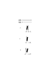
図7は、図2で説明した記録ヘッドに対して製造バラツキなどでインク吐出口列の回転方向θの傾きが異なる2つの記録ヘッドを示す。 FIG. 7 shows two recording heads having different inclinations in the rotation direction θ of the ink discharge port array due to manufacturing variations or the like with respect to the recording head described in FIG.
インク吐出口列Aのインク吐出口n1は、インク吐出口n12に対して図7の+X方向に1200dpiで3dotの約63μm離れている。また、インク吐出口列Bのインク吐出口n1は、インク吐出口n12に対して図7の−X方向に1200dpiで3dotの約63μm離れている。 The ink ejection port n1 of the ink ejection port array A is separated from the ink ejection port n12 by about 63 μm of 3 dots at 1200 dpi in the + X direction in FIG. Further, the ink ejection port n1 of the ink ejection port array B is separated from the ink ejection port n12 by about 63 μm, which is 3 dots at 1200 dpi in the −X direction of FIG.
図10は、図7のインク吐出口列Aとインク吐出口列Bの往路方向から吐出されるドットの2列間の記録位置のズレを調整するためのチェックパターンであり、図11は、図10の−3〜−1を拡大したものである。 FIG. 10 is a check pattern for adjusting the displacement of the recording position between two rows of dots ejected from the forward direction of the ink ejection port array A and the ink ejection port array B in FIG. 10 −3 to −1 is enlarged.
インク吐出口列Aから吐出されるドットの記録位置を基準として、インク吐出口列Bの吐出タイミングを異ならせて往路で記録する。+方向は、吐出タイミングを遅く、−方向は吐出タイミングを早くしている。 Recording is performed in the forward path by changing the ejection timing of the ink ejection port array B with reference to the recording position of the dots ejected from the ink ejection port array A. In the + direction, the discharge timing is delayed, and in the-direction, the discharge timing is advanced.
調整分解能は、1200dpiの約21μmでドットの記録位置のズレを−3から+3の7段階のパターンの範囲内で調整することができる。 The adjustment resolution is approximately 21 μm of 1200 dpi, and the deviation of the dot recording position can be adjusted within a range of seven patterns from -3 to +3.
図10の−3から+3の7段階のパターンでズレ量が最も少ないパターンである−2は、インク吐出口列Aで記録する黒丸と、インク吐出口列Bで記録する白丸の2列間のX方向のズレ量d2は約63μmである。 In the pattern of −3 to +3 in FIG. 10, the pattern −2 having the smallest deviation amount is between two black circles recorded by the ink ejection port array A and white circles recorded by the ink ejection port array B. The amount of deviation d2 in the X direction is about 63 μm.
−1は、インク吐出口列Aで記録する黒丸に対してインク吐出口列Bで記録する白丸の記録タイミングが1200dpiで1画素遅く、2列間のX方向のズレ量d1は約84μmである。 −1 indicates that the recording timing of white circles recorded in the ink discharge port array B is 1200 pixels slower than the black circles recorded in the ink discharge port array A by one pixel, and the shift amount d1 in the X direction between the two columns is about 84 μm. .
−3は、インク吐出口列Aで記録する黒丸に対して、インク吐出口列Bで記録する白丸の記録タイミングが1200dpiで1画素早く、2列間のX方向のズレ量は約84μmである。 -3 indicates that the recording timing of the white circle recorded by the ink ejection port array B is 1200 dpi faster than the black circle recorded by the ink ejection port array A by one pixel, and the amount of deviation in the X direction between the two columns is about 84 μm. .
以上、図2のように傾きθが無い記録ヘッドでは、最も少ない記録位置のズレ量が0μmであるのに対し、図7に示した傾きθを持つ記録ヘッドでは、最も少ない記録位置のズレ量でさえ63μmで記録位置のズレが大きくなり、画像劣化の原因となる。 As described above, in the recording head having no inclination θ as shown in FIG. 2, the smallest recording position deviation amount is 0 μm, whereas in the recording head having the inclination θ shown in FIG. 7, the smallest recording position deviation amount. Even at 63 μm, the displacement of the recording position becomes large, which causes image deterioration.
図5(b)は、図7の記録ヘッドを用いて記録する場合に生じる回転方向θの傾きによる記録位置のズレを調整するためチェックパターンである。チェックパターンAはインク吐出口列Aの往路で記録し、図6はそれを拡大したものである。チェックパターンBはインク吐出口列Bの往路で記録し、図8はそれを拡大したものである。 FIG. 5B is a check pattern for adjusting the shift of the recording position due to the inclination of the rotation direction θ that occurs when recording is performed using the recording head of FIG. The check pattern A is recorded on the forward path of the ink discharge port array A, and FIG. 6 is an enlarged view of the check pattern A. The check pattern B is recorded on the forward path of the ink discharge port array B, and FIG. 8 is an enlarged view of the check pattern B.
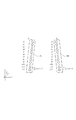
図9は、図5(b)の傾斜印刷の調整で行われるインク吐出口列の分割について示したものである。インク吐出口群2401は、吐出口列Aの吐出口n1から吐出口n6および吐出口列Bの吐出口n1から吐出口n6に対応している。インク吐出口群2402は、吐出口列Aの吐出口n7から吐出口n12および吐出口列Bの吐出口n7から吐出口n12に対応している。インク吐出口群2403は、吐出口列Aのインク吐出口n1から吐出口n4および吐出口列Bの吐出口n1から吐出口n4に対応している。インク吐出口群2404は、吐出口列Aの吐出口n5から吐出口n8および吐出口列Bの吐出口n5から吐出口n8に対応している。インク吐出口群2405は、吐出口列Aの吐出口n9から吐出口n12および吐出口列Bの吐出口n9から吐出口n12に対応している。ノズル列を2分割した場合、基準となるインク吐出口群2401に対してインク吐出口群2402の吐出タイミングを異ならせて、往路で記録するものである。+方向は吐出タイミングを遅く、−方向は吐出タイミングを早くしている。
FIG. 9 shows the division of the ink ejection port array performed in the tilt printing adjustment of FIG. The ink
ノズル列を3分割した場合、インク吐出口群2403に対してインク吐出口群2404の吐出タイミングを異ならせて、往路で記録する。同様に、インク吐出口群2404に対してインク吐出口群2405の吐出タイミングを異ならせて往路で記録する。+方向は吐出タイミングを遅く、−方向は吐出タイミングを早くしている。
When the nozzle row is divided into three, the ejection timing of the ink ejection port group 2404 is made different from that of the ink
分割数調整分解能は、1200dpiの約21μmでドットの記録位置のズレを−2から+2の5段階のパターンの範囲内で調整することができる。 The resolution for adjusting the number of divisions can be adjusted within a 5-step pattern range of −2 to +2 at a dot recording position shift of about 21 μm of 1200 dpi.
図6に示した0は、インク吐出口列Aを分割せずに記録し記録位置のズレ量d3は約84μmである。+1は、吐出口列Aを2分割し吐出口群2401に対して吐出口群2402で記録するタイミングが1200dpiで1画素遅く、インク吐出口列Aの記録位置のズレ量d4は約63μmである。+2は、吐出口列Aを3分割し吐出口群2403に対して吐出口群2404で記録するタイミングが1200dpiで1画素遅く、さらに基準となる吐出口群2403に対して吐出口群2405で記録するタイミングが1200dpiで2画素遅い。この時のインク吐出口列Aの記録位置のズレ量d5は約42μmである。−1は、吐出口列を2分割し吐出口群2401に対して吐出口群2402で記録するタイミングが1200dpiで1画素早く、インク吐出口列Aの記録位置のズレ量d2は約105μmである。−2は、吐出口列を3分割し吐出口群2403に対してインク吐出口群2404で記録するタイミングが1200dpiで1画素早く、さらに基準となる吐出口群2403に対して吐出口群2405で記録するタイミングが1200dpiで2画素早い。この時のインク吐出口列Aの記録位置のズレ量d2は約126μmである。
In FIG. 6, 0 is recorded without dividing the ink discharge port array A, and the shift amount d3 of the recording position is about 84 μm. +1 is that the ejection port array A is divided into two and the recording timing of the
図8に示す0は、インク吐出口列Bを分割せずに記録したもので記録幅d3は約84μmである。+1は、吐出口列を2分割し吐出口群2401に対して吐出口群2402で記録するタイミングが1200dpiで1画素遅く、インク吐出口列Bの記録位置のズレ量d4は約105μmである。+2は、吐出口列を3分割し吐出口群2403に対して吐出口群2404で記録するタイミングが遅く、さらに基準となる図24の吐出口群2403に対して吐出口群2405で記録するタイミングが1200dpiで2画素遅い。この時のインク吐出口列Bの記録位置のズレ量d5は約126μmである。−1は、吐出口列を2分割し吐出口群2401に対して吐出口群2402で記録するタイミングが1200dpiで1画素早く、インク吐出口列Bの記録位置のズレ量d2は約63μmである。−2は、吐出口列を3分割し吐出口群2403に対してインク吐出口群2404で記録するタイミングが1200dpiで1画素早く、さらに基準となる図24の吐出口群2403に対して吐出口群2405で記録するタイミングが1200dpiで2画素早い。この時のインク吐出口列Bの記録位置のズレ量d1は約42μmである。
8 shown in FIG. 8 is recorded without dividing the ink discharge port array B, and the recording width d3 is about 84 μm. For +1, the ejection port array is divided into two and the recording timing of the
図15(a)は、図7の記録ヘッドを用いたインク吐出口列内の記録位置ズレ調整について説明するためのフローチャートである。まず、ステップ1501において、吐出口列A内のθ方向の記録位置ズレを調整するためのチェックパターンAを記録する。 FIG. 15A is a flowchart for explaining the adjustment of the recording position in the ink discharge port array using the recording head of FIG. First, in step 1501, a check pattern A for adjusting a recording position shift in the θ direction in the ejection port array A is recorded.
ステップ1502において、吐出口列A内のθ方向の記録位置のズレを調整するための図5のチェックパターンAから、最も記録位置のズレ量が少ない、つまり主走査方向に対するズレが少ない+2の番号を選択する。ステップ1503において、選択された+2を記録位置調整値Aとして記録装置本体のEEPROMに格納する。ステップ1504において、吐出口列B内のθ方向の記録位置のズレを調整するためのチェックパターンBを記録する。ステップ1505において、吐出口列B内のθ方向の記録位置ズレを調整するための図5(a)のチェックパターンBから、最も記録位置のズレ量が少ない、つまり主走査方向に対するズレが少ない−2の番号を選択する。ステップ1506において、選択された−2の番号を記録位置調整値Bとして記録装置本体のEEPROMに格納する。
In step 1502, from the check pattern A in FIG. 5 for adjusting the deviation of the recording position in the θ direction in the ejection port array A, the number +2 is the smallest amount of deviation of the recording position, that is, the deviation in the main scanning direction is the smallest. Select. In
図12は、図7のインク吐出口列内Aとインク吐出口列内BのEEPROMに格納された記録位置調整値を反映させて往路で記録した、2列のインク吐出口列間の記録位置のズレを調整するためのチェックパターンである。図13は、図12の0〜+2を拡大したものである。 FIG. 12 shows the recording positions between the two ink ejection port arrays that are recorded on the forward path by reflecting the recording position adjustment values stored in the EEPROM in the ink ejection port arrays A and B in FIG. This is a check pattern for adjusting the deviation of the image. FIG. 13 is an enlarged view of 0 to +2 in FIG.
インク吐出口列Aから吐出されるドットの記録位置を基準として、インク吐出口列Bからの吐出タイミングを異ならせて往路で記録する。+方向は、吐出タイミングを遅く、−方向は吐出タイミングを早くしている。 Recording is performed in the forward path by changing the ejection timing from the ink ejection port array B with reference to the recording position of the dots ejected from the ink ejection port array A. In the + direction, the discharge timing is delayed, and in the-direction, the discharge timing is advanced.
調整分解能は1200dpiの約21μmであり、ドットの記録位置のズレを−3から+3の7段階のパターンの範囲内で調整することができる。 The adjustment resolution is about 21 μm of 1200 dpi, and the deviation of the dot recording position can be adjusted within the range of seven patterns from -3 to +3.
図13に示す+1は、インク吐出口列Aで記録する黒丸と、インク吐出口列Bで記録する白丸が重なって、2列間のX方向のズレ量d2は約42μmである。+2は、インク吐出口列Aで記録する黒丸に対して、インク吐出口列Bで記録する白丸の記録タイミングが1200dpiで1画素遅く、2列間のX方向のズレ量d1は約63μmである。0は、インク吐出口列Aで記録する黒丸に対して、インク吐出口列Bで記録する白丸の記録タイミングが1200dpiで1画素早く、2列間のX方向のズレ量d3は約63μmである。 In FIG. 13, +1 indicates that the black circle recorded by the ink ejection port array A and the white circle recorded by the ink ejection port array B overlap, and the misalignment amount d2 in the X direction between the two columns is about 42 μm. +2 indicates that the recording timing of the white circle recorded by the ink ejection port array B is one pixel slower at 1200 dpi than the black circle recorded by the ink ejection port array A, and the shift amount d1 in the X direction between the two columns is about 63 μm. . For 0, the recording timing of the white circle recorded in the ink ejection port array B is 1200 pixels faster than the black circle recorded in the ink ejection port array A, and the displacement d3 in the X direction between the two columns is about 63 μm. .
ここで、図15(b)は、図7の記録ヘッドを用いたインク吐出口列間の記録位置ズレ調整について説明するためのフローチャートである。ステップ1507において、θ方向の記録位置を調整する記録位置調整値Aと記録位置調整値Bに基づきインク吐出口列Aとインク吐出口列Bの2列間の記録位置ズレを調整するための図12のチェックパターンCを記録する。ステップ1508において、インク吐出口列Aとインク吐出口列Bの2列間の記録位置ズレを調整するための図12のチェックパターンCから、2列間のX方向のズレ量が最も少ない+1の番号を選択する。
Here, FIG. 15B is a flowchart for explaining the adjustment of the recording position deviation between the ink discharge port arrays using the recording head of FIG. FIG. 10 is a diagram for adjusting the recording position deviation between the two rows of the ink ejection port array A and the ink ejection port array B based on the recording position adjustment value A and the recording position adjustment value B for adjusting the recording position in the θ direction in Step 1507. Twelve check patterns C are recorded. In step 1508, from the check pattern C in FIG. 12 for adjusting the printing position deviation between the two rows of the ink ejection port array A and the ink ejection port array B, the displacement amount in the X direction between the two columns is the
ステップ1509において、選択された+1の番号を記録位置調整値Cとして記録装置本体のEEPROMに格納する。この格納された記録位置調整値を基に記録を行う。以上のように、記録装置、記録ヘッドの製造バラツキ及び記録ヘッドの取り付けバラツキによって生じる記録ドットの記録位置のズレによる画像劣化を低減することができる。 In step 1509, the selected +1 number is stored as the recording position adjustment value C in the EEPROM of the recording apparatus main body. Recording is performed based on the stored recording position adjustment value. As described above, it is possible to reduce image deterioration due to deviation of the recording position of the recording dots caused by the manufacturing variation of the recording apparatus and the recording head and the mounting variation of the recording head.
ところがこの方法では、最初にインク吐出口列内の記録位置のずれを調整するための記録位置調整値を各インク吐出口列毎に求める必要がある。そして、その調整値でインク吐出口列内の記録位置のズレを調整した状態で2列間の記録位置のズレを調整することになる。したがって、記録位置調整を二段階で行う必要があり、非常に使い勝手が悪い。本発明は上記問題点を解消するためになされたもので、その目的とするところは、記録装置、記録ヘッドの製造バラツキ、記録ヘッドの取り付け精度による記録ドットの記録位置のズレによる画像劣化を防止する記録装置および記録時の記録位置ズレの調整方法を提供することである。さらには、各吐出口列内の記録位置調整値を反映させなくても、2列間の記録位置のズレを調整できる調整方法を提供する。 However, in this method, it is necessary to first obtain a recording position adjustment value for adjusting a deviation of the recording position in the ink ejection port array for each ink ejection port column. Then, the deviation of the printing position between the two rows is adjusted in a state where the deviation of the printing position in the ink discharge port row is adjusted with the adjustment value. Therefore, it is necessary to adjust the recording position in two stages, which is very inconvenient. The present invention has been made to solve the above-described problems, and its object is to prevent image deterioration due to deviations in the recording positions of recording dots due to manufacturing variations of the recording apparatus and recording head, and mounting accuracy of the recording head. And a method for adjusting a recording position shift during recording. Furthermore, the present invention provides an adjustment method that can adjust the displacement of the print position between the two rows without reflecting the print position adjustment value in each discharge port row.
上述の課題を解決する本発明は、複数の吐出口が配列されることにより構成される第1吐出口列と第2吐出口列を有する記録ヘッドを前記第1、第2の吐出口列を構成する吐出口の配列方向と交差する走査方向に走査させながら前記記録ヘッドよりインクを吐出させて記録媒体に画像を記録するインクジェット記録装置であって、前記第1吐出口列の一部の連続して配置される複数の吐出口と前記第1吐出口列の他部の連続して配置される複数の吐出口との相対的なインクの吐出タイミングを、前記第1の吐出口列の前記一部の複数の吐出口からの吐出タイミングを基準として前記第1の吐出口列の前記他部の複数の吐出口からの吐出のタイミングを変更することにより調整するための第1調整値を取得するための第1パターンと、前記第2吐出口列の一部の連続して配置される複数の吐出口と前記第2吐出口列の吐出口のうちの他部の連続して配置される複数の吐出口との相対的なインクの吐出タイミングを、前記第1の吐出口列の前記一部の複数の吐出口からの吐出タイミングを基準として前記第1の吐出口列の前記他部の複数の吐出口からの吐出タイミングを変更することにより調整するための第2調整値を取得するための第2パターンと、前記第1吐出口列の前記一部の連続して配置される複数の吐出口と前記第2吐出口列の前記一部の連続して配置される複数の吐出口との相対的なインクの吐出タイミングを調整するための第3調整値を取得するための第3パターンと、を記録ヘッドに記録させるパターン記録手段と、前記第1パターンと前記第2パターンと前記第3パターンとを記録した後に、前記第1パターンに基づいて前記第1調整値をメモリに格納することと、前記第2パターンに基づいて前記第2調整値をメモリに格納することと、前記第3パターンに基づいて前記第3調整値をメモリに格納することと、を行う制御手段と、を有することを特徴とする。 The present invention that solves the above-described problems includes a recording head having a first discharge port array and a second discharge port array configured by arranging a plurality of discharge ports. An inkjet recording apparatus that records an image on a recording medium by ejecting ink from the recording head while scanning in a scanning direction that intersects an arrangement direction of the constituent ejection ports, and is a continuous part of the first ejection port array The relative ejection timing of ink between the plurality of ejection ports arranged in this manner and the plurality of ejection ports arranged continuously in the other part of the first ejection port array Obtaining a first adjustment value for adjustment by changing the timing of ejection from the plurality of ejection ports in the other part of the first ejection port array on the basis of ejection timing from some of the plurality of ejection ports A first pattern for performing the second pattern Relative ink ejection between a plurality of ejection ports arranged continuously in a part of the outlet row and a plurality of ejection ports arranged continuously in the other portion of the ejection ports of the second ejection port row Changing the timing of the discharge from the plurality of other outlets of the first outlet row with reference to the timing of the discharge from the plurality of outlets of the first outlet row. A second pattern for obtaining a second adjustment value for adjustment according to the above, a plurality of the plurality of discharge ports arranged continuously in the first discharge port row, and the one of the second discharge port row Pattern recording means for causing the recording head to record a third pattern for obtaining a third adjustment value for adjusting the relative ink ejection timing with a plurality of ejection ports arranged continuously in the unit; , The first pattern, the second pattern, and the third pattern. Storing the first adjustment value in a memory based on the first pattern, storing the second adjustment value in a memory based on the second pattern, and Control means for storing the third adjustment value in a memory based on three patterns.
本発明によれば、記録装置、記録ヘッドの製造バラツキ、記録ヘッドの取り付け精度による記録位置のズレによる画像劣化を低減することができる。さらには、各吐出口列内の記録位置調整値を反映させなくても、2列間の記録位置のズレを調整できる調整方法を提供することができる効果を有する。 According to the present invention, it is possible to reduce image deterioration due to deviation of a recording position due to manufacturing variations of a recording apparatus and a recording head, and mounting accuracy of the recording head. Furthermore, there is an effect that it is possible to provide an adjustment method capable of adjusting the shift of the print position between the two rows without reflecting the print position adjustment value in each discharge port row.
(実施形態1)
図3は、本発明の一実施形態に係るインクジェット記録装置の制御構成を示すブロック図である。なお、本実施形態のインクジェット記録装置の機械的構成は図1に示したものと同様とする。メインバスライン305に対して夫々アクセスする画像入力部303、それに対応する画像信号処理部304、中央制御部CPU300といった印字データやファームウェアを制御する処理手段と、操作部306、回復系制御回路307、ヘッド温度制御回路314、ヘッド駆動制御回路315、主走査方向へのキャリッジ駆動制御回路316、副走査方向への紙送り制御回路317といったハード系処理手段とに大別される。CPU300は、通常ROM(読み出し専用メモリ)301とRAM(任意のアドレスにアクセスできるメモリ)302とEEPROM318を有し、入力情報に対して適正な記録条件を与えて記録ヘッド313を駆動して記録を行う。又、RAM302内には、予め記録ヘッドの回復タイミングチャートを実行するプログラムが格納されており、必要に応じて予備吐出条件等の回復条件を回復系制御回路307、記録ヘッド、保温ヒータ等に与える。回復系モータ308は、前述したような記録ヘッド313とこれに当接離間するクリーニングブレード309やキャップ310、吸引ポンプ311を駆動する。ヘッド駆動制御回路315は、記録ヘッド313のインク吐出用電気熱変換体の駆動条件を実行するもので、通常予備吐出や記録用インク吐出を記録ヘッド313に行わせる。
(Embodiment 1)
FIG. 3 is a block diagram showing a control configuration of the ink jet recording apparatus according to the embodiment of the present invention. The mechanical configuration of the ink jet recording apparatus of the present embodiment is the same as that shown in FIG. An
ちなみにヘッド駆動制御回路315は、CPU300の制御のもとに、記録ヘッドの各ノズル列毎、またはあるノズル列と他のノズル列(ノズル列間)との駆動タイミング調整の制御も行う。
Incidentally, under the control of the
一方、記録ヘッド313のインク吐出用の電気熱変換体が設けられている基板には、保温ヒータが設けられている場合もあり、記録ヘッド内のインク温度を所望設定温度に加熱調整することができる。又、ダイオードセンサ312は、同様に前記基板に設けられているもので、実質的な記録ヘッド内部のインク温度を測定するためのものである。ダイオードセンサ312も同様に、基板にではなく外部に設けられていても良く記録ヘッドの周囲近傍にあっても良い。
On the other hand, the substrate on which the electrothermal transducer for ink ejection of the
本発明の第1の実施形態では、図7に示したインク吐出口列が1列で構成された記録ヘッド2つを用いた場合について説明を行う。図5(a)(b)は、図7の記録ヘッドを用いて記録する場合に生じる回転方向θの傾きによる記録位置のズレと、インク吐出口列Aとインク吐出口列Bの2列間の記録位置のズレを調整するためチェックパターンである。 In the first embodiment of the present invention, a case will be described in which two recording heads each having one ink discharge port array shown in FIG. 7 are used. FIGS. 5A and 5B are diagrams showing the displacement of the recording position due to the inclination of the rotation direction θ that occurs when recording is performed using the recording head of FIG. 7, and the interval between the two ink ejection port arrays A and B. This is a check pattern for adjusting the shift of the recording position.
また、図5(a)のチェックパターンAはインク吐出口列Aの往路で記録し、図5(b)のチェックパターンAの+2〜−2と同じパターンで、図6はそれを拡大したものである。 Further, the check pattern A in FIG. 5A is recorded in the forward path of the ink discharge port array A, and is the same pattern as +2 to −2 in the check pattern A in FIG. 5B, and FIG. 6 is an enlarged view thereof. It is.
図5(a)のチェックパターンBはインク吐出口列Bの往路で記録し、図5(b)のチェックパターンBの+2〜−2と同じパターンで、図8はそれを拡大したものである。 The check pattern B of FIG. 5A is recorded in the forward path of the ink ejection port array B, and is the same pattern as +2 to −2 of the check pattern B of FIG. 5B, and FIG. 8 is an enlarged view thereof. .
チェックパターンAとチェックパターンBの調整分解能は、1200dpiの約21μmでドットの記録位置のズレを−2から+2の5段階のパターンの範囲内で調整することができる。 The adjustment resolution of the check pattern A and the check pattern B is about 21 μm of 1200 dpi, and the deviation of the dot recording position can be adjusted within a range of five steps from −2 to +2.
図5(a)のチェックパターンCは、インク吐出口列A内のθ方向の記録位置のズレの調整で用いた基準のインク吐出口群2403と、インク吐出口列Bのθ方向の記録位置のズレの調整で用いた基準のインク吐出口群2403の往路で記録したものである。図21は図5のチェックパターンCの−2〜0を拡大したものである。吐出口列A内のθ方向のズレの調整で用いた基準のインク吐出口群2403から吐出されるドットの記録位置を基準として、インク吐出口列B内のθ方向の記録位置のズレの調整で用いた基準のインク吐出口群2403からの吐出タイミングを異ならせて往路で記録する。+方向は、吐出タイミングを遅く、−方向は吐出タイミングを早くしている。
The check pattern C in FIG. 5A shows the reference ink
図21に示す−1は、インク吐出口列A内のθ方向の記録位置のズレの調整で用いた基準のインク吐出口群2403で記録する黒丸と、インク吐出口列B内のθ方向の記録位置のズレの調整で用いた基準のインク吐出口群2403で記録する白丸が重なる。2列間のX方向のズレ量d2は約21μmである。0は、インク吐出口列A内のθ方向の記録位置のズレの調整で用いた基準のインク吐出口群2403で記録する黒丸に対して、インク吐出口列B内のθ方向のズレ調整で用いた基準のインク吐出口群2403による白丸の記録タイミングが1200dpiで1画素遅い。2列間のX方向のズレ量d1は約42μmである。−2は、インク吐出口列A内のθ方向のズレ調整で用いた基準のインク吐出口群2403で記録する黒丸に対して、インク吐出口列B内のθ方向の記録位置のズレの調整で用いた基準のインク吐出口群2403による白丸の記録タイミングが1200dpiで1画素早い。2列間のX方向のズレ量d3は約42μmである。チェックパターンCの調整分解能は、1200dpiの約21μmでドットの記録位置のズレを−3から+3の7段階のパターンの範囲内で調整することができる。
-1 shown in FIG. 21 indicates a black circle recorded by the reference ink
また、図14は、図7の記録ヘッドを用いた記録位置のズレの調整について説明するための本実施形態でのフローチャートである。 FIG. 14 is a flowchart in the present embodiment for explaining the adjustment of the displacement of the recording position using the recording head of FIG.
まず、ステップ1401において、図5の吐出口列A内のθ方向の記録位置のズレを調整するためのチェックパターンAと、吐出口列B内のθ方向の記録位置のズレを調整するためのチェックパターンBを記録する。さらにインク吐出口列Aとインク吐出口列Bの2列間の記録位置のズレを調整するためチェックパターンCを記録する。ステップ1402において、吐出口列A内のθ方向の記録位置のズレを調整するための図5のチェックパターンAから、最も記録位置のズレ量が少ない+2の番号を選択する。ステップ1403において、吐出口列B内のθ方向の記録位置のズレを調整するための図5のチェックパターンBから、最も記録位置のズレ量が少ない−2の番号を選択する。ステップ1404において、インク吐出口列Aとインク吐出口列Bの2列間の記録位置のズレを調整するためチェックパターンCから、最も記録位置のズレ量が少ない−1の番号を選択する。ステップ1405において、選択された+2を記録位置調整値Aとして記録装置本体のEEPROMに格納する。ステップ1406において、選択された−2の番号を記録位置調整値Bとして記録装置本体のEEPROMに格納する。ステップ1407において、選択された−1を記録位置調整値Cとして記録装置本体のEEPROMに格納する。
First, in step 1401, a check pattern A for adjusting the recording position deviation in the θ direction in the ejection port array A in FIG. 5 and a recording position deviation in the θ direction in the ejection port array B are adjusted. Record check pattern B. Further, a check pattern C is recorded in order to adjust the shift of the recording position between the two ink ejection port arrays A and B. In step 1402, the number +2 with the smallest recording position deviation is selected from the check pattern A in FIG. 5 for adjusting the recording position deviation in the θ direction in the ejection port array A. In step 1403, the number -2 having the smallest recording position deviation is selected from the check pattern B in FIG. 5 for adjusting the deviation of the recording position in the θ direction in the ejection port array B. In
これら格納した記録位置調整値AからCを用いて、記録を行う。 Recording is performed using the stored recording position adjustment values A to C.
以上、図7のインク吐出口列が回転方向の傾きθを持つ記録ヘッドでは、従来の記録位置調整方法では、最も少ない記録位置のズレ量が63μmとなっていた。対して本実施形態で説明した記録位置ズレの調整方法を用いると、最も少ない記録位置のズレ量が21μmとなり、記録位置のズレを低減することができる。このように、記録装置、記録ヘッドの製造バラツキ及び記録ヘッドの取り付けバラツキによって生じる記録ドットの記録位置のズレによる画像劣化を低減することができ、さらには、各吐出口列内の記録位置調整値を反映させなくても、2列間の記録位置のズレを調整できる調整方法を提供することができた。本実施形態では、図7に示したインク吐出口列が1列で構成された記録ヘッドを2つ備え、インク吐出口列Aはブラックインクを吐出し、インク吐出口列Bはシアンインクを吐出する場合について説明した。しかしこれに限定されるものではない。各インク吐出口列からマゼンタ、イエローなどの異なるインクを吐出する場合においても適用できる。また、本実施形態では約2plのインク滴を用いて説明したが、これに限定されるものではない。約2plよりも大きなインク滴でも、小さなインク滴でも良く、さらに色ごと、吐出口列ごとにインク滴の大きさを異ならせてもよい。 As described above, in the recording head in which the ink discharge port array in FIG. 7 has the inclination θ in the rotation direction, the smallest recording position deviation amount is 63 μm in the conventional recording position adjustment method. On the other hand, when the recording position deviation adjusting method described in the present embodiment is used, the smallest recording position deviation amount is 21 μm, and the recording position deviation can be reduced. In this way, it is possible to reduce image deterioration due to deviation of the recording position of the recording dots caused by the manufacturing variation of the recording apparatus and the recording head and the mounting variation of the recording head, and further, the recording position adjustment value in each ejection port array Thus, an adjustment method capable of adjusting the shift of the recording position between the two rows without reflecting the above can be provided. In this embodiment, two recording heads each having one ink discharge port array shown in FIG. 7 are provided, the ink discharge port array A discharges black ink, and the ink discharge port array B discharges cyan ink. Explained when to do. However, the present invention is not limited to this. The present invention can also be applied to the case where different inks such as magenta and yellow are ejected from each ink ejection port array. In the present embodiment, the ink droplet of about 2 pl has been described, but the present invention is not limited to this. Ink droplets larger than about 2 pl or small ink droplets may be used, and the size of the ink droplets may be different for each color and each ejection port array.
本実施形態における調整値の取得に関しては様様な手法がある。ユーザーがPCプリンタドライバを通して直接インクジェット記録装置本体に選択した値を手動で入力しても良い。光学センサー等でチェックパターンを読み取り、最も記録位置のズレ量が少ないパターンを検出し、検出されたパターンの値を自動で入力しても良い。また、すべてのチェックパターンは、吐出タイミングを変化させて記録する方法について説明したが、あらかじめ用意した複数の記録データを基に作成する場合も含む。上記チェックパターンは、記録装置内で作成してもよいし、記録データを生成するホスト装置内で作成してもよい。また、すべてのパターンを往路において記録する方法について説明したが、これに限定されるものではなく、復路において記録する場合も含む。また、本実施形態では、インク吐出口列内のθ方向の記録位置のズレを判別し、調整できる図5のチェックパターンA、Bや、インク吐出口列A、Bの2列間の記録位置のズレを判別し、調整できる図5のチェックパターンCを用いて説明した。これに限定されずインク吐出口列内の記録位置のズレや2列間の記録位置のズレを判別し、調整できるような他のパターンを用いてもよい。また、本実施形態では、図5のチェックパターンから記録位置調整値を選択した後、決定し、EEPROMに格納する順番をチェックパターンA、B、Cの順としたが、これに限定されるものではない。例えばチェックパターンB、C、Aの順番のように異なる順番でもよい。また、θ方向の記録位置のズレは、図7で説明したように記録ヘッド102の製造バラツキにより、インク吐出口列がθ方向へ傾くことで発生すると説明したが、これに限定されるものではなく、以下のような2つの場合についても同様の効果を得ることが出来る。図25(c)は、主走査方向の復路で、図2の記録ヘッド102のインク吐出口列Aから吐出されたドットが記録媒体3501に着弾した状態を模式的に示したものである。記録ドット3502は、インク吐出口列Aのインク吐出口n12から吐出され、記録ドット3503は、インク吐出口列Aのインク吐出口n1から吐出されて記録媒体3501に着弾する。図25(a)は、インクジェット記録装置本体への記録ヘッド102の取り付けバラツキに起因して、記録ヘッドが記録媒体面に対してZ方向に傾いた状態を示したものである。インク吐出口列Aのインク吐出口n12と記録媒体間の距離Z1は、インク吐出口列Aのインク吐出口n1と記録媒体間の距離Z2よりも長くなっている。この時、インク吐出口列Aから同時に吐出された記録ドット3502と3503は、インク吐出口と記録媒体までの距離が短い記録ドット3503が初めに記録媒体に着弾し、インク吐出口と記録媒体までの距離が長い記録ドット3502が最後に記録媒体に着弾する。そのため、記録媒体上に形成された記録ドット列は、θ方向に記録位置がずれる。また、図24(b)の矢印3504と矢印3505は、インク吐出口から吐出された記録ドットの吐出速度を示し、矢印の長さが記録ドットの吐出速度に比例している。インク吐出口列Aから同時に吐出された記録ドットは、インク吐出速度が速い記録ドット3505が初めに記録媒体に着弾し、インク吐速度が遅い記録ドット3504が最後に記録媒体に着弾する。そのため、主走査しながら記録すると、記録媒体上に形成された記録ドット列はθ方向に記録位置がずれる。本実施形態では、インク吐出口列内のθ方向の記録位置のズレの調整で用いた基準のインク吐出口群を、インク吐出口列Aのインク吐出口n1からn4またはインク吐出口列Bの吐出口n1からn4とした。しかしながら、図26および図27のようにインク吐出口列Aのインク吐出口n5からn8またはインク吐出口列Bのインク吐出口n5からn8としてもよい。図30は、インクジェット記録装置本体への記録ヘッド102の取り付けバラツキに起因して、記録ヘッド102がθ方向へ傾いた状態を示す図である。このように記録ヘッド102がθ方向へ傾いた状態で記録媒体へ記録を行った場合にも本実施形態と同様の効果を得ることが出来る。
There are various methods for obtaining adjustment values in the present embodiment. The value selected by the user directly into the main body of the inkjet recording apparatus may be manually input through the PC printer driver. It is also possible to read the check pattern with an optical sensor or the like, detect the pattern with the smallest amount of deviation of the recording position, and automatically input the value of the detected pattern. Further, although all the check patterns have been described with respect to the method of recording by changing the ejection timing, it includes the case of creating based on a plurality of recording data prepared in advance. The check pattern may be created in the recording device or in the host device that generates the recording data. Moreover, although the method for recording all patterns in the forward path has been described, the present invention is not limited to this, and includes the case of recording in the backward path. Further, in the present embodiment, the recording position between the two columns of the check patterns A and B in FIG. 5 and the ink ejection port arrays A and B that can determine and adjust the deviation of the recording position in the θ direction in the ink ejection port array. This has been described using the check pattern C of FIG. However, the present invention is not limited to this, and other patterns that can discriminate and adjust the displacement of the recording position in the ink discharge port array and the displacement of the recording position between the two rows may be used. In this embodiment, the recording position adjustment value is selected from the check pattern shown in FIG. 5 and then determined and stored in the EEPROM in the order of check patterns A, B, and C. However, the present invention is not limited to this. is not. For example, different orders such as the order of check patterns B, C, and A may be used. Further, it has been described that the deviation of the recording position in the θ direction occurs when the ink discharge port array is inclined in the θ direction due to manufacturing variations of the
本実施形態で用いた2つの記録ヘッドのインク吐出口数とインク吐出口の間隔はそれぞれ等しい。しかし、図31のように2つの記録ヘッドのインク吐出口間隔が、インク吐出口列Aでは1/600インチ、インク吐出口列Bでは1/300インチと異なる場合においても、本実施形態を適用できる。すなわち、インク吐出口列内のθ方向の記録位置のズレの調整で用いる基準となるインク吐出口群をインク吐出口列Aのn1からn4とインク吐出口列Bのn1からn4とするのである。また、図32のように2つの記録ヘッドのインク吐出口数が、インク吐出口列Aでは12個、インク吐出口列Bでは18個と異なる場合においても、本実施形態は適用できる。すなわち、インク吐出口列内のθ方向の記録位置のズレの調整で用いる基準となるインク吐出口群をインク吐出口列Aのn1からn4とインク吐出口列Bのn1からn6とすることで同様の効果を得ることができる。 The number of ink ejection ports and the interval between the ink ejection ports of the two recording heads used in this embodiment are the same. However, the present embodiment is applied even when the interval between the ink discharge ports of the two recording heads is different from 1/600 inch in the ink discharge port array A and 1/300 inch in the ink discharge port array B as shown in FIG. it can. That is, the reference ink discharge port groups used for adjusting the shift of the recording position in the θ direction in the ink discharge port array are n1 to n4 of the ink discharge port array A and n1 to n4 of the ink discharge port array B. . The present embodiment can also be applied to the case where the number of ink ejection ports of the two recording heads is different from 12 in the ink ejection port array A and 18 in the ink ejection port array B as shown in FIG. That is, the reference ink discharge port groups used for adjusting the shift of the recording position in the θ direction in the ink discharge port array are n1 to n4 of the ink discharge port array A and n1 to n6 of the ink discharge port array B. Similar effects can be obtained.
(実施形態2)
本発明の第2の実施形態では、図16に示したインク吐出口列が2列で構成された記録ヘッドを2つ用いた場合について説明を行う。図16は、ブラックインクを吐出するインク吐出口列Aとシアンインクを吐出するインク吐出口列Bの2列で構成された記録ヘッド2601と、マゼンタインクを吐出するインク吐出口列Cとイエローインクを吐出するインク吐出口列Dの2列で構成された記録ヘッド2602の2つの記録ヘッドを示す。
(Embodiment 2)
In the second embodiment of the present invention, a case will be described where two recording heads each having two ink discharge port arrays shown in FIG. 16 are used. FIG. 16 shows a
記録ヘッドは、吐出口数L=12個で、吐出口の間隔が1/600インチにより記録画素密度が600dpiになるように構成されている。また、記録ヘッドからの吐出量は、1滴あたり約2plのインク滴が吐出可能なように構成されており、このインク滴を安定して吐出するための吐出周波数は30kHzで吐出速度は、約20m/秒となっている。この記録ヘッドを搭載したキャリッジの主走査方向への速度は、主走査方向にインク滴を1200dpi間隔に記録すると約25インチ/秒となる。図16の記録ヘッドは、製造バラツキによりインク吐出口列の回転方向θへ傾いている。記録ヘッド1601のインク吐出口列Aのインク吐出口n1は、インク吐出口n12に対して+X方向に1200dpiで3dotの約63μm離れている。記録ヘッド1601のインク吐出口列Bのインク吐出口n1は、インク吐出口n12に対して−X方向に1200dpiで2dotの約42μm離れている。記録ヘッド1602のインク吐出口列Cのインク吐出口n1は、インク吐出口n12に対して+X方向に1200dpiで2dotの約42μm離れている。記録ヘッド1602のインク吐出口列Dのインク吐出口n1は、インク吐出口n12に対して−X方向に1200dpiで3dotの約63μm離れている。また、図16に示したインク吐出口列Aからインク吐出口列Dに対して、2つ以上のインク吐出口群に分割した図は、図9と同じである。図19は、図16の記録ヘッドを用いて記録する場合に生じる回転方向θの傾きによる記録位置のズレを調整するためチェックパターンと、2列のインク吐出口列間の記録位置のズレを調整するためのチェックパターンである。チェックパターンAは、インク吐出口列Aの往路で記録し、図5(b)のチェックパターンAの+2〜−2と同じで、図6はそれを拡大したものである。チェックパターンBは、インク吐出口列Bの往路で記録し、図8はそれを拡大したものである。チェックパターンBの+2〜−2が、図17のチェックパターンの+2〜−2に対応している。チェックパターンCは、インク吐出口列Cの往路で記録し、図19はそれを拡大したものである。チェックパターンCの+2〜−2が図19のチェックパターンの+2〜−2に対応している。チェックパターンDは、インク吐出口列Dの往路で記録し、図5(b)のチェックパターンBの+2〜−2と同じで、図8はそれを拡大したものである。チェックパターンA、B、C、Dの調整分解能は、1200dpiの約21μmでドットの記録位置のズレを−2から+2の5段階のパターンの範囲内で調整することができる。図8において、0はインク吐出口列Bを分割せずに記録し、記録位置のズレ量d3は約42μmである。 The recording head is configured so that the number of ejection ports is L = 12, the interval between the ejection ports is 1/600 inch, and the recording pixel density is 600 dpi. Further, the ejection amount from the recording head is configured so that about 2 pl of ink droplets can be ejected per droplet. The ejection frequency for stably ejecting these ink droplets is 30 kHz, and the ejection speed is about 20 m / sec. The speed in the main scanning direction of the carriage on which this recording head is mounted is about 25 inches / second when ink droplets are recorded at intervals of 1200 dpi in the main scanning direction. The recording head in FIG. 16 is inclined in the rotation direction θ of the ink discharge port array due to manufacturing variations. The ink ejection port n1 of the ink ejection port array A of the recording head 1601 is separated from the ink ejection port n12 by about 63 μm of 3 dots at 1200 dpi in the + X direction. The ink ejection port n1 of the ink ejection port array B of the recording head 1601 is separated from the ink ejection port n12 by about 42 μm of 2 dots at 1200 dpi in the −X direction. The ink ejection port n1 of the ink ejection port array C of the recording head 1602 is separated from the ink ejection port n12 by about 42 μm of 2 dots at 1200 dpi in the + X direction. The ink ejection port n1 of the ink ejection port array D of the recording head 1602 is separated from the ink ejection port n12 by about 63 μm of 3 dots at 1200 dpi in the −X direction. Also, the drawing in which the ink discharge port array A to the ink discharge port array D shown in FIG. 16 are divided into two or more ink discharge port groups is the same as FIG. FIG. 19 shows the adjustment of the recording position deviation between the check pattern and the two ink ejection port arrays in order to adjust the recording position deviation caused by the inclination of the rotation direction θ that occurs when recording is performed using the recording head of FIG. It is a check pattern for The check pattern A is recorded in the forward path of the ink discharge port array A, and is the same as +2 to −2 of the check pattern A in FIG. 5B, and FIG. 6 is an enlarged view thereof. The check pattern B is recorded on the forward path of the ink discharge port array B, and FIG. 8 is an enlarged view of the check pattern B. +2 to -2 of the check pattern B corresponds to +2 to -2 of the check pattern in FIG. The check pattern C is recorded on the forward path of the ink discharge port array C, and FIG. 19 is an enlarged view of the check pattern C. The check pattern C +2 to -2 corresponds to the check pattern +2 to -2 in FIG. The check pattern D is recorded in the forward path of the ink discharge port array D and is the same as +2 to −2 of the check pattern B in FIG. 5B, and FIG. 8 is an enlarged view thereof. The adjustment resolution of the check patterns A, B, C, and D is approximately 21 μm of 1200 dpi, and the shift of the dot recording position can be adjusted within a range of five patterns from −2 to +2. In FIG. 8, 0 is recorded without dividing the ink discharge port array B, and the shift amount d3 of the recording position is about 42 μm.
+1は吐出口列Bを2分割し、基準のインク吐出口群である図9の吐出口群2401に対して吐出口群2402で記録するタイミングが1200dpiの1画素遅く、インク吐出口列Aの記録位置のズレ量d4は約63μmである。+2は、吐出口列Bを3分割し、基準のインク吐出口群である図17の吐出口群2403に対して吐出口群2404で記録するタイミングが1200dpiの1画素遅い。さらに基準のインク吐出口群である図174の吐出口群2403に対して吐出口群2405で記録するタイミングが1200dpiの2画素遅い。この時のインク吐出口列Bの記録位置のズレ量d5は約84μmである。
+1 divides the ejection port array B into two, and the recording timing of the
−1は、吐出口列Bを2分割し、基準のインク吐出口群である吐出口群2401に対して吐出口群2402で記録するタイミングが1200dpiの1画素早く、インク吐出口列Bの記録位置のズレ量d2は約21μmである。−2は、吐出口列Bを3分割し、吐出口群2403に対してインク吐出口群2404で記録するタイミングが1200dpiの1画素早い。さらに基準のインク吐出口群である図24の吐出口群2401に対して吐出口群2405で記録するタイミングが1200dpiの2画素早い。この時のインク吐出口列Bの記録位置のズレ量d2は約42μmである。図18の0は、インク吐出口列Cを分割せずに記録し、記録位置のズレ量d3は約42μmである。+1は、吐出口列Cを2分割し、吐出口群2401に対して吐出口群2402で記録するタイミングが1200dpiの1画素遅く、インク吐出口列Bの記録位置のズレ量d4は約21μmである。+2は、吐出口列Cを3分割し、吐出口群2403に対して吐出口群2404で記録するタイミングが1200dpiの1画素遅く、さらに吐出口群2403に対して吐出口群2405で記録するタイミングが1200dpiの2画素遅い。この時のインク吐出口列Bの記録位置のズレ量d5は約42μmである。−1は、吐出口列Cを2分割し、吐出口群2401に対して吐出口群2402で記録するタイミングが1200dpiの1画素早く、インク吐出口列Bの記録位置のズレ量d2は約63μmである。−2は、吐出口列Cを3分割し、吐出口群2403に対してインク吐出口群2404で記録するタイミングが1200dpiの1画素早く、さらに吐出口群2403に対して吐出口群2405で記録するタイミングが1200dpiの2画素早い。この時のインク吐出口列Bの記録位置のズレ量d2は約84μmである。
-1 divides the ejection port array B into two, and the recording timing of the
また、図19のチェックパターンEは、インク吐出口列A内のθ方向の記録位置のズレの調整で用いた基準のインク吐出口群2403と、インク吐出口列B内のθ方向の記録位置のズレの調整で用いた基準のインク吐出口群2043の往路で記録したものである。図24(b)が図19のチェックパターンEの0〜−2を拡大したものである。同様にチェックパターンFは、インク吐出口列A内のθ方向の記録位置のズレの調整で用いた基準のインク吐出口群2403と、インク吐出口列C内のθ方向の記録位置のズレの調整で用いた基準のインク吐出口群2403の往路で記録したものである。図24(a)が図19のチェックパターンFの+1〜+3を拡大したものである。チェックパターンGは、インク吐出口列C内のθ方向の記録位置のズレの調整で用いた基準のインク吐出口群2403と、インク吐出口列D内のθ方向の記録位置のズレの調整で用いた基準のインク吐出口群2403の往路で記録したものである。図22が図19のチェックパターンGの0〜+2を拡大したものである。+方向は、吐出タイミングを遅く、−方向は吐出タイミングを早くしている。チェックパターンE、F、Gの調整分解能は、1200dpiの約21μmでドットの記録位置のズレを−3から+3の7段階のパターンの範囲内で調整できる。
Further, the check pattern E in FIG. 19 shows the reference ink
図24(b)の−1は、インク吐出口列A内のθ方向の記録位置のズレの調整で用いた基準のインク吐出口群2403で記録する黒丸と、インク吐出口列B内のθ方向の記録位置のズレの調整で用いた基準のインク吐出口群2403で記録する白丸が重なっている。2列間のX方向のズレ量は約21μmである。0は、インク吐出口列A内のθ方向の記録位置のズレの調整で用いた基準のインク吐出口群2403で記録する黒丸に対して、インク吐出口列B内のθ方向の記録位置のズレの調整で用いた基準のインク吐出口群2403で記録する白丸の記録タイミングが遅い。2列間のX方向のズレ量は約42μmである。
In FIG. 24B, -1 indicates a black circle recorded by the reference ink
−2は、インク吐出口列A内のθ方向の記録位置のズレの調整で用いた基準のインク吐出口群2403で記録する黒丸に対して、インク吐出口列B内のθ方向の記録位置のズレの調整で用いた基準のインク吐出口群2403で記録する白丸の記録タイミングが早い。2列間のX方向のズレ量は約42μmである。
-2 represents the recording position in the θ direction in the ink ejection port array B with respect to the black circle recorded in the reference ink
図24(a)の+2は、インク吐出口列A内のθ方向の記録位置のズレの調整で用いた基準のインク吐出口群2403で記録する黒丸と、インク吐出口列C内のθ方向の記録位置のズレの調整で用いた基準のインク吐出口群2403で記録する白丸が重なっている。2列間のX方向のズレ量は約21μmである。+3は、インク吐出口列A内のθ方向の記録位置のズレの調整で用いた基準のインク吐出口群2403で記録する黒丸に対して、インク吐出口列C内のθ方向の記録位置のズレの調整で用いた基準のインク吐出口群2403で記録する白丸の記録タイミングが遅い。2列間のX方向のズレ量は約42μmである。+1は、インク吐出口列A内のθ方向の記録位置のズレの調整で用いた基準のインク吐出口群2403で記録する黒丸に対して、インク吐出口列C内のθ方向の記録位置のズレの調整で用いた基準のインク吐出口群2403で記録する白丸の記録タイミングが早い。2列間のX方向のズレ量は約42μmである。
In FIG. 24A, +2 indicates a black circle recorded by the reference ink
図22の+1は、インク吐出口列C内のθ方向の記録位置のズレの調整で用いた基準のインク吐出口群2403で記録する黒丸と、インク吐出口列D内のθ方向の記録位置のズレの調整で用いた基準のインク吐出口群2403で記録する白丸が重なっている。2列間のX方向のズレ量は約21μmである。+2は、インク吐出口列C内のθ方向の記録位置のズレの調整で用いた基準のインク吐出口群2403で記録する黒丸に対して、インク吐出口列D内のθ方向の記録位置のズレの調整で用いた基準のインク吐出口群2403で記録する白丸の記録タイミングが遅い。2列間のX方向のズレ量は約42μmである。0は、インク吐出口列C内のθ方向の記録位置のズレの調整で用いた基準のインク吐出口群2403で記録する黒丸に対して、インク吐出口列D内のθ方向の記録位置のズレの調整で用いた基準のインク吐出口群2403で記録する白丸の記録タイミングが早い。2列間のX方向のズレ量は約42μmである。
+1 in FIG. 22 indicates a black circle recorded by the reference ink
また、図33は、図16の記録ヘッドを用いた記録位置のズレの調整について説明するための本実施形態でのフローチャートである。 FIG. 33 is a flowchart in the present embodiment for explaining the adjustment of the displacement of the recording position using the recording head of FIG.
まず、ステップ4001において、吐出口列A内のθ方向の記録位置のズレを調整するためのチェックパターンAを記録する。同様に各吐出口列B、C、Dのθ方向の記録位置ずれのためのチェックパターンを記録する。さらに、吐出口列Aと吐出口列Bの記録位置のズレを調整するためのチェックパターンEを記録する。同様に、吐出口列AとC、吐出口列CとDとの間での記録位置のズレを調整するためのチェックパターンを記録する。
First, in
ステップ4002において、吐出口列A内のθ方向の記録位置のズレを調整するための図19のチェックパターンAから最も記録位置のズレ量が少ない+2の番号を選択する。
In
ステップ4003において、吐出口列B内のθ方向の記録位置のズレを調整するための図19のチェックパターンBから最も記録位置のズレ量が少ない−1の番号を選択する。
In
ステップ4004において、吐出口列C内のθ方向の記録位置のズレを調整するための図19のチェックパターンCから最も記録位置のズレ量が少ない+1の番号を選択する。 In step 4004, the number +1 with the smallest recording position deviation is selected from the check pattern C in FIG. 19 for adjusting the recording position deviation in the θ direction in the ejection port array C.
ステップ4005において、吐出口列D内のθ方向の記録位置のズレを調整するための図19のチェックパターンDから最も記録位置のズレ量が少ない−2の番号を選択する。 In step 4005, the number -2 having the smallest recording position deviation is selected from the check pattern D in FIG. 19 for adjusting the recording position deviation in the θ direction in the ejection port array D.
ステップ4006において、インク吐出口列Aとインク吐出口列Bの2列間の記録位置のズレを調整するためのチェックパターンEから2列間のX方向のズレ量が最も少ない−1の番号を選択する。ステップ4007において、インク吐出口列Aとインク吐出口列Cの2列間の記録位置のズレを調整するためのチェックパターンFから2列間のX方向のズレ量が最も少ない+2の番号を選択する。ステップ4008において、インク吐出口列Cとインク吐出口列Dの2列間の記録位置のズレを調整するためのチェックパターンGから2列間のX方向のズレ量が最も少ない+1の番号を選択する。ステップ4009において、選択された+2を記録位置調整値Aとして記録装置本体のEEPROMに格納する。ステップ4010において、選択された−1の番号を記録位置調整値Bとして記録装置本体のEEPROMに格納する。ステップ4011において、選択された+1の番号を記録位置調整値Cとして記録装置本体のEEPROMに格納する。ステップ4012において、選択された−2の番号を記録位置調整値Dとして記録装置本体のEEPROMに格納する。
In
ステップ4013において、選択された−1の番号を記録位置調整値Eとして記録装置本体のEEPROMに格納する。ステップ4014において、選択された+2の番号を記録位置調整値Fとして記録装置本体のEEPROMに格納する。ステップ4015において、選択された+1の番号を記録位置調整値Gとして記録装置本体のEEPROMに格納する。これら格納した記録位置調整値AからGを用いて記録を行う。
In
以上のように、図16のインク吐出口列が傾きθを持つ記録ヘッドでは、従来の記録位置調整方法を用いると、最も少ない記録位置のズレ量が63μmとなっていた。しかし本実施形態で説明した記録位置ズレの調整方法を用いると、最も少ない記録位置のズレ量が21μmとなり、記録位置のズレを低減することができる。 As described above, in the recording head in which the ink discharge port array of FIG. 16 has the inclination θ, the smallest recording position shift amount is 63 μm when the conventional recording position adjustment method is used. However, when the recording position deviation adjusting method described in the present embodiment is used, the smallest recording position deviation amount is 21 μm, and the recording position deviation can be reduced.
このように、記録装置、記録ヘッドの製造バラツキ及び記録ヘッドの取付誤差によって生じる記録ドット位置のズレによる画像劣化を低減することができる。さらには、各吐出口列内の記録位置調整値を反映させなくても、2列間の記録位置のズレを調整できる調整方法を提供することができた。本実施形態では、図16に示したインク吐出口列が2列で構成された記録ヘッドを2つ備え、インク吐出口列Aはブラックインク、Bはシアンインク、Cはマゼンタインク、Dはイエローインクを吐出する場合について説明した。しかしながら、これに限定されるものではなく、レッド、ブルーなどの異なる色インクを吐出し、インク吐出口列が2列以上の記録ヘッドを2つ以上備えた場合においても本実施形態は適用できる。 In this way, it is possible to reduce image deterioration due to deviations in recording dot positions caused by manufacturing variations of the recording apparatus and the recording head and mounting errors of the recording head. Furthermore, it is possible to provide an adjustment method that can adjust the displacement of the print position between the two rows without reflecting the print position adjustment value in each discharge port row. In this embodiment, two recording heads each having two ink discharge port arrays shown in FIG. 16 are provided, the ink discharge port array A is black ink, B is cyan ink, C is magenta ink, and D is yellow. The case where ink is ejected has been described. However, the present embodiment is not limited to this, and the present embodiment can also be applied to a case where different color inks such as red and blue are ejected and two or more recording heads each having two or more ink ejection port arrays are provided.
また、本実施形態では約2plのインク滴を用いて説明したが、これに限定されるものではなく、大小のインク滴でも良く、さらに色ごと吐出口列ごとに異なるインク滴の大きさにおいても本実施形態は適用可能である。本実施形態では、ユーザーがPCプリンタドライバを通して直接インクジェット記録装置本体に選択した値を手動で入力しても良い。光学センサー等でチェックパターンを読み取り、最も記録位置のズレ量が少ないパターンを検出し、検出されたパターンの値を自動で入力しても良い。 In the present embodiment, the ink droplet of about 2 pl has been described. However, the present invention is not limited to this, and may be a large or small ink droplet. Further, the ink droplet size may be different for each color for each ejection port array. This embodiment is applicable. In the present embodiment, a value selected by the user directly into the ink jet recording apparatus main body through a PC printer driver may be manually input. It is also possible to read the check pattern with an optical sensor or the like, detect the pattern with the smallest amount of deviation of the recording position, and automatically input the value of the detected pattern.
本実施形態では、すべてのチェックパターンは、吐出タイミングを変化させて記録する方法について説明したが、これに限定されるものではなく、すべてのチェックパターンは、あらかじめ用意した複数の記録データを基に作成する場合も含む。上記チェックパターンは、記録装置内で作成してもよいし、記録データを生成するホスト装置内で作成してもよい。本実施形態では、すべてのパターンを往路において記録する方法について説明したが、これに限定されるものではなく、復路において記録する場合も含む。 In the present embodiment, the method for recording all check patterns by changing the ejection timing has been described. However, the present invention is not limited to this, and all check patterns are based on a plurality of recording data prepared in advance. Including the case of creating. The check pattern may be created in the recording device or in the host device that generates the recording data. In the present embodiment, the method of recording all patterns in the forward path has been described. However, the present invention is not limited to this, and includes a case of recording in the backward path.
本実施形態では、インク吐出口列内のθ方向の記録位置のズレを判別し、調整できる図19のチェックパターンAからDや、インク吐出口列AとB、インク吐出口列AとC、インク吐出口列CとDの2列間の記録位置のズレを判別し、調整できる図19のチェックパターンEからGを用いて説明した。しかし、インク吐出口列内の記録位置のズレや2列間の記録位置のズレを判別し、調整できる他のパターンを用いてもよい。本実施形態では、θ方向の記録位置のズレは、図19で説明したように記録ヘッド102の製造バラツキにより、インク吐出口列がθ方向へ傾くことで発生すると説明した。しかしこれに限定されるものではない。図23(c)は、主走査方向の復路で、図2の記録ヘッド102のインク吐出口列Aから吐出されたドットが記録媒体3501に着弾した状態を示したものである。記録ドット3502は、インク吐出口列Aのn12から吐出され、記録ドット3503は、インク吐出口列Aのn1から吐出されて記録媒体3501に着弾する。図23(a)は、インクジェット記録装置本体への記録ヘッド102の取り付けバラツキに起因して、記録ヘッドが記録媒体面に対してZ方向に傾いた状態を示したものである。インク吐出口列Aのインク吐出口n12と記録媒体間の距離Z1は、インク吐出口列Aのn1と記録媒体間の距離Z2よりも長くなっている。この時、インク吐出口列Aから同時に吐出された記録ドット3502と3503は、インク吐出口と記録媒体までの距離が短い記録ドット3503が初めに記録媒体に着弾する。そしてインク吐出口と記録媒体までの距離が長い記録ドット3502が最後に記録媒体に着弾するする。そのため記録媒体上に形成された記録ドット列は、θ方向に記録位置がずれる。
In the present embodiment, check pattern A to D, ink discharge port arrays A and B, ink discharge port arrays A and C in FIG. The description has been given using check patterns E to G in FIG. 19 that can discriminate and adjust the deviation of the printing position between the two ink ejection port rows C and D. However, other patterns that can determine and adjust the displacement of the recording position in the ink ejection port array and the displacement of the recording position between the two rows may be used. In the present embodiment, it has been described that the deviation of the recording position in the θ direction occurs when the ink discharge port array is inclined in the θ direction due to manufacturing variations of the
また、図35(b)の矢印3504と矢印3505は、インク吐出口から吐出された記録ドットの吐出速度を示し、矢印の長さが記録ドットの吐出速度に比例している。インク吐出口列Aから同時に吐出された記録ドットは、インク吐出速度が速い記録ドット3505が初めに記録媒体に着弾する。そしてインク吐速度が遅い記録ドット3504が最後に記録媒体に着弾する。そのため記録媒体上に形成された記録ドット列は、θ方向に記録位置がずれる。
Also,
本実施形態では、インク吐出口列内のθ方向の記録位置のズレの調整で用いた基準のインク吐出口群をn1からn4としたが、これに限定されるものではない。図25および図26および図27および図28のように、インク吐出口列内のθ方向の記録位置のズレの調整で用いる基準のインク吐出口群を、インク吐出口列A、B、C、Dいずれかの吐出口n5からn8を用いてもよい。 In this embodiment, the reference ink discharge port group used for adjusting the shift of the recording position in the θ direction in the ink discharge port array is set to n1 to n4. However, the present invention is not limited to this. As shown in FIG. 25, FIG. 26, FIG. 27, and FIG. 28, the reference ink discharge port group used for adjusting the shift of the recording position in the θ direction in the ink discharge port row is the ink discharge port row A, B, C, Any one of the discharge ports n5 to n8 may be used.
本実施形態で用いた2つの記録ヘッドのインク吐出口数とインク吐出口の間隔はそれぞれ等しい。しかし、これに限定されるものではない。図32(a)のように2つの記録ヘッドのインク吐出口間隔が、インク吐出口列Aとインク吐出口列Bでは1/600インチ、インク吐出口列Cとインク吐出口列Dでは1/300インチと異なる場合においても適用可能である。基準となるインク吐出口群をインク吐出口列Aのn1からn4、インク吐出口列Bのn1からn4、インク吐出口列Cのn1からn2、インク吐出口列Dのn1からn2としてもよい。また、図32(b)のように2つの記録ヘッドのインク吐出口数が、インク吐出口列Aとインク吐出口列Bでは12個、インク吐出口列Cとインク吐出口列Dでは18個と異なる場合においても適用できる。インク吐出口列内のθ方向の記録位置のズレの調整で用いる基準となるインク吐出口群をインク吐出口列Aとインク吐出口列Bのn1からn4とインク吐出口列Cとインク吐出口列Dのn1からn6としてもよい。 The number of ink ejection ports and the interval between the ink ejection ports of the two recording heads used in this embodiment are the same. However, it is not limited to this. As shown in FIG. 32A, the ink discharge port interval between the two recording heads is 1/600 inch for the ink discharge port array A and the ink discharge port column B, and 1/600 for the ink discharge port column C and the ink discharge port column D. The present invention can be applied even when it is different from 300 inches. The reference ink discharge port groups may be n1 to n4 of the ink discharge port array A, n1 to n4 of the ink discharge port array B, n1 to n2 of the ink discharge port array C, and n1 to n2 of the ink discharge port array D. . Further, as shown in FIG. 32B, the number of ink ejection ports of the two recording heads is 12 in the ink ejection port array A and the ink ejection port array B, and 18 in the ink ejection port array C and the ink ejection port array D. It can also be applied in different cases. The reference ink discharge port groups used for adjusting the shift of the recording position in the θ direction in the ink discharge port row are n1 to n4 of the ink discharge port row A and the ink discharge port row B, the ink discharge port row C, and the ink discharge port. It may be n1 to n6 in column D.
図20は、インクジェット記録装置本体への記録ヘッド102の取り付けバラツキに起因して、記録ヘッド102がθ方向へ傾いた状態を示している。このように記録ヘッド102がθ方向へ傾いた状態で記録媒体へ記録を行うと記録位置がずれる。ただし、インク吐出口列Aとインク吐出口列Bから吐出された記録ドットは、θ方向に同じ量だけ傾いて記録媒体へ着弾するため、インク吐出口列A内とインク吐出口列B内のθ方向の記録位置のズレを調整する記録位置調整値は等しくなる。そのため、本実施形態で用いた図19の吐出口列B内の記録位置のズレを調整するチェックパターンBは、チェックパターンAで代用が可能である。同様に、本実施形態で用いた図19の吐出口列D内の記録位置のズレを調整するチェックパターンDは、チェックパターンCで代用が可能である。また、インク吐出口列Aとインク吐出口列Bが同一チップ内にある場合は、インク吐出口列Aとインク吐出口列Bの距離は一意的に決まる。したがって本実施形態で用いた図19のインク吐出口列Aとインク吐出口列Bの2列間の記録位置のズレを調整するチェックパターンEについても必要がなくなる。同様に、インク吐出口列Cとインク吐出口列Dが同一チップ内にある場合は、インク吐出口列Cとインク吐出口列Dの距離は一意的に決まる。本実施形態で用いた図19のインク吐出口列Cとインク吐出口列Dの2列間の記録位置のズレを調整するチェックパターンGについても必要がなくなる。このように、同一チップや同一カートリッジ内のインク吐出口列内のθ方向の記録位置のズレが同じである場合は、ある1つのインク吐出口列を基準(代表)として記録位置調整値を求めても良い。又、各インク吐出口列間の距離が一意的に決まる場合は記録位置調整値を求めずに固定値としても良い。
FIG. 20 shows a state in which the
(実施形態3)
本実施形態では、2種類のインク吐出口列のインク吐出口列間の駆動タイミングを調整するのに使用するインク吐出口が、少なくとも1種類のインク吐出口列はインク吐出口列の基準となるインク吐出口を含んでいる場合について説明する。
(Embodiment 3)
In the present embodiment, at least one type of ink ejection port array serves as a reference for the ink ejection port array, and the ink ejection ports used to adjust the drive timing between the two types of ink ejection port arrays. A case where the ink discharge port is included will be described.
図36は、本実施形態を説明する記録ヘッドを示す。 FIG. 36 shows a recording head for explaining the present embodiment.
記録ヘッドは、吐出口の間隔が1/600インチで吐出口数が18個の記録ヘッドAと吐出口の間隔が1/600インチで吐出口数が12個の記録ヘッドBからなる。 The recording head includes a recording head A having an ejection port interval of 1/600 inch and 18 ejection ports and a recording head B having an ejection port interval of 1/600 inch and 12 ejection ports.
記録ヘッドAのインク吐出口列内の回転方向θ方向の記録位置のズレの調整で用いるインク吐出口群は、n1からn6、n7からn12、n13からn18の3つとし、基準となるインク吐出口群をn1からn6とする。 There are three ink ejection port groups, n1 to n6, n7 to n12, and n13 to n18, used for adjusting the recording position deviation in the rotational direction θ direction in the ink ejection port array of the recording head A. Let the exit group be n1 to n6.
記録ヘッドBのインク吐出口列内の回転方向θ方向の記録位置のズレの調整で用いるインク吐出口群は、n1からn4、n5からn8、n9からn12の3つとし、基準となるインク吐出口群をn1からn4とする。 There are three ink ejection port groups, n1 to n4, n5 to n8, and n9 to n12, used for adjusting the displacement of the recording position in the rotational direction θ direction in the ink ejection port array of the recording head B. Let the exit group be n1 to n4.
また、記録ヘッドAのインク吐出口n1と記録ヘッドBのインク吐出口n1は、記録媒体を搬送する副走査方向に、1/600インチで吐出口数4個分の4/600インチずれて配置されている。 Further, the ink ejection port n1 of the recording head A and the ink ejection port n1 of the recording head B are arranged with a shift of 1/600 inch and 4/600 inch corresponding to the number of ejection ports of 4 in the sub-scanning direction for conveying the recording medium. ing.
記録ヘッドA、Bの各インク吐出口列内の回転方向θ方向の記録位置のズレの調整については、前記実施例と同様に基準インク吐出口群に対して、非基準インク吐出口群の駆動タイミングをずらして調整を行う。駆動タイミングのずらし方は、前記実施例の様にデータをずらしても良いし、吐出パルスを加えるタイミングをオフセットさせても良い。 Regarding the adjustment of the displacement of the recording position in the rotational direction θ direction in each ink discharge port array of the recording heads A and B, the driving of the non-reference ink discharge port group with respect to the reference ink discharge port group is performed as in the above embodiment. Adjust the timing. For shifting the drive timing, the data may be shifted as in the above embodiment, or the timing at which the ejection pulse is applied may be offset.
次に、記録ヘッドA、Bの各インク吐出口列間の記録位置のズレの調整について説明を行う。インク吐出口列間の記録位置のズレの調整で使用するインク吐出口は、記録ヘッドAが、基準インク吐出口群n1からn6を含むn1からn8までの8つのインク吐出口を使用する。記録ヘッドBは、前記記録ヘッドAと記録媒体を搬送する副走査方向が同じ位置にあたるn5からn12までの8つのインク吐出口を使用する。 Next, adjustment of the displacement of the recording position between the ink discharge port arrays of the recording heads A and B will be described. As the ink discharge ports used for adjusting the displacement of the recording position between the ink discharge port arrays, the recording head A uses eight ink discharge ports from n1 to n8 including the reference ink discharge port groups n1 to n6. The recording head B uses eight ink ejection ports from n5 to n12 where the sub-scanning direction for conveying the recording head A and the recording medium is the same position.
図37は、本実施形態の記録ヘッドAとBのインク吐出口列間の記録位置のズレの調整をするためのチェックパターンを示す。黒丸は、記録ヘッドAのn1からn8までの8つのインク吐出口から吐出されたパターンを示し、白丸は、記録ヘッドBのn5からn12までの8つのインク吐出口から吐出されたパターンである。記録ヘッドAから吐出された黒丸のパターンを基準インク吐出口列として、記録ヘッドBから吐出される白丸のパターンを記録する駆動タイミングを主走査の往路方向にずらした3種類のチェックパターンを示す。黒丸と白丸からなるパターンの走査方向の幅が最も狭い幅d1のチェックパターンを記録した時の駆動タイミングの調整値+1をインク吐出口列間の記録位置調整値として記録装置本体のEEPROM等の記憶領域に格納する。 FIG. 37 shows a check pattern for adjusting the displacement of the recording position between the ink discharge port arrays of the recording heads A and B of this embodiment. The black circles indicate patterns ejected from the eight ink ejection ports from n1 to n8 of the recording head A, and the white circles are patterns ejected from the eight ink ejection ports from n5 to n12 of the recording head B. Three types of check patterns are shown in which the drive timing for recording the white circle pattern ejected from the recording head B is shifted in the forward direction of the main scanning, using the black circle pattern ejected from the recording head A as a reference ink ejection port array. The drive timing adjustment value +1 when the check pattern having the narrowest width d1 in the scanning direction of the pattern composed of black circles and white circles is recorded is stored as the print position adjustment value between the ink discharge port arrays in the EEPROM of the printing apparatus main body Store in the area.
上記記録ヘッドA、Bの各インク吐出口列内の回転方向θ方向の記録位置のズレの調整(説明文は前記実施例と同様のため省略)と、記録ヘッドA、Bの各インク吐出口列間の記録位置のズレの調整を前記記憶領域に格納された調整値+1を基に実施した状態で画像データの記録を行う。 Adjustment of the displacement of the recording position in the rotation direction θ direction in each ink discharge port array of the recording heads A and B (description is omitted because it is the same as in the above embodiment), and each ink discharge port of the recording heads A and B The image data is recorded in a state where the adjustment of the shift of the recording position between the columns is performed based on the adjustment value +1 stored in the storage area.
以上の様に、記録ヘッドAとBからなる少なくとも2種類のインク吐出口列間の記録位置のズレを調整するのに使用するインク吐出口が、少なくともどちらか1種類(記録ヘッドA)のインク吐出口列に関しては、インク吐出口列内の回転方向θ方向の記録位置のズレを調整するのに使用する基準となるインク吐出口を含んでいることで、前記実施例で説明したように効果がある。つまり、インク吐出口列内の回転方向θ方向の記録位置のズレを調整した状態でのインク吐出口列間のズレ量を低減させることができる。 As described above, at least one of the ink discharge ports (recording head A) is used for adjusting the displacement of the recording position between at least two types of ink discharge port arrays composed of the recording heads A and B. With respect to the ejection port array, the ink ejection port serving as a reference used for adjusting the displacement of the recording position in the rotation direction θ direction in the ink ejection port array includes the effect as described in the above embodiment. There is. That is, it is possible to reduce the amount of misalignment between the ink ejection port arrays in a state where the displacement of the recording position in the rotation direction θ direction in the ink ejection port array is adjusted.
更に、本実施形態で説明した様にインク吐出口列内の回転方向θ方向の記録位置のズレを調整するのに使用する基準となるインク吐出口位置が記録媒体を搬送する副走査方向に異なる少なくとも2種類のインク吐出口列を備えた構成において、
インク吐出口列間の記録位置のズレを調整するのに使用するインク吐出口位置が記録媒体を搬送する副走査方向に同じ位置とすることで、各インク吐出口列のチェックパターンを同一記録走査で記録できるため、記録媒体を搬送させたときの搬送バラツキによる記録位置のズレの発生を防止できる。また、各インク吐出口列のチェックパターンを同一記録走査で記録できるため、記録位置をズレを調整する調整値を求めるためのチェックパターンの記録に要する時間短縮も可能となる。
Further, as described in the present embodiment, the reference ink discharge port position used for adjusting the displacement of the recording position in the rotation direction θ direction in the ink discharge port array is different in the sub-scanning direction for conveying the recording medium. In a configuration including at least two types of ink ejection port arrays,
The ink discharge port position used to adjust the displacement of the print position between the ink discharge port arrays is set to the same position in the sub-scanning direction in which the recording medium is conveyed. Therefore, it is possible to prevent the deviation of the recording position due to the conveyance variation when the recording medium is conveyed. Further, since the check pattern of each ink discharge port array can be recorded by the same recording scan, it is possible to shorten the time required for recording the check pattern for obtaining an adjustment value for adjusting the shift of the recording position.
101 インクカートリッジ
102 記録ヘッド
103 紙送りローラ
104 補助ローラ
105 給紙ローラ
106 キャリッジ
201 吐出口
700 中央制御部(CPU)
701 ROM
702 RAM
703 画像入力部
704 画像信号処理部
705 バスライン
706 操作部
DESCRIPTION OF
701 ROM
702 RAM
703 Image input unit 704 Image signal processing unit 705 Bus line 706 Operation unit
Claims (8)
前記第1吐出口列の一部の連続して配置される複数の吐出口と前記第1吐出口列の他部の連続して配置される複数の吐出口との相対的なインクの吐出タイミングを、前記第1の吐出口列の前記一部の複数の吐出口からの吐出タイミングを基準として前記第1の吐出口列の前記他部の複数の吐出口からの吐出タイミングを変更することにより調整するための第1調整値を取得するための第1パターンと、前記第2吐出口列の一部の連続して配置される複数の吐出口と前記第2吐出口列の吐出口のうちの他部の連続して配置される複数の吐出口との相対的なインクの吐出タイミングを、前記第2の吐出口列の前記一部の複数の吐出口からの吐出タイミングを基準として前記第2の吐出口列の前記他部の複数の吐出口からの吐出タイミングを変更することにより調整するための第2調整値を取得するための第2パターンと、前記第1吐出口列の前記一部の連続して配置される複数の吐出口と前記第2吐出口列の前記一部の連続して配置される複数の吐出口との相対的なインクの吐出タイミングを調整するための第3調整値を取得するための第3パターンと、を記録ヘッドに記録させるパターン記録手段と、
前記第1パターンと前記第2パターンと前記第3パターンとを記録した後に、前記第1パターンに基づいて前記第1調整値をメモリに格納することと、前記第2パターンに基づいて前記第2調整値をメモリに格納することと、前記第3パターンに基づいて前記第3調整値をメモリに格納することと、を行う制御手段と、を有することを特徴とするインクジェット記録装置。 A recording head having a first discharge port array and a second discharge port array configured by arranging a plurality of discharge ports intersects the array direction of the discharge ports constituting the first and second discharge port arrays. An inkjet recording apparatus that records an image on a recording medium by ejecting ink from the recording head while scanning in a scanning direction,
Relative ink ejection timing between a plurality of continuously disposed ejection ports in a part of the first ejection port array and a plurality of continuously disposed ejection ports in the other part of the first ejection port array By changing the discharge timing from the plurality of other discharge ports of the first discharge port row with reference to the discharge timing from the plurality of discharge ports of the part of the first discharge port row Of the first pattern for obtaining the first adjustment value for adjustment, the plurality of discharge ports arranged continuously in part of the second discharge port row, and the discharge ports of the second discharge port row The relative ejection timing of the ink with respect to the plurality of ejection ports arranged continuously in the other part is determined based on the ejection timing from the plurality of ejection ports of the part of the second ejection port array. The discharge timing from the plurality of discharge ports in the other part of the two discharge port arrays is changed. Said second pattern and, wherein the first outlet row plurality of discharge ports which the is arranged a part of the succession of the second ejection port array for acquiring second adjustment value for adjusting by Pattern recording means for causing the recording head to record a third pattern for obtaining a third adjustment value for adjusting the relative ink ejection timing with a plurality of ejection ports arranged continuously. When,
After recording the first pattern, the second pattern, and the third pattern, storing the first adjustment value in a memory based on the first pattern, and the second based on the second pattern. An ink jet recording apparatus comprising: control means for storing an adjustment value in a memory and storing the third adjustment value in a memory based on the third pattern.
前記調整手段は、記録データを前記主走査方向にオフセットさせることによりインクの吐出タイミングを調整することを特徴とする請求項1から4のいずれかに記載のインクジェット記録装置。 Relative ink ejection between the part of the plurality of continuous ejection openings of the first ejection port array and the part of the plurality of continuous ejection ports of the first ejection port array based on the first adjustment value. The timing is adjusted, and relative to the part of the plurality of continuous outlets of the first outlet array and the part of the plurality of consecutive outlets of the second outlet array based on the third adjustment value A plurality of the plurality of ejection ports arranged continuously in the part of the first ejection port array and the plurality of parts arranged in the part of the second ejection port array by adjusting the ink ejection timing. Adjusting means for adjusting the discharge timing of the ink relative to the discharge port of
5. The ink jet recording apparatus according to claim 1, wherein the adjusting unit adjusts ink ejection timing by offsetting print data in the main scanning direction. 6.
前記調整手段は、記録データの吐出開始位置を前記主走査方向にオフセットさせることによりインクの吐出タイミングを調整することを特徴とする請求項1から4のいずれかに記載のインクジェット記録装置。 Based on the first adjustment value, the relative ejection timing of ink between one ejection port group of the first ejection port array and the other ejection port group of the first ejection port array is adjusted, and the second adjustment value For adjusting the relative ink discharge timings of the plurality of continuous discharge ports of the first discharge port array and the plurality of continuous discharge ports of the second discharge port array based on Having means,
5. The ink jet recording apparatus according to claim 1, wherein the adjusting unit adjusts an ink discharge timing by offsetting a discharge start position of print data in the main scanning direction. 6.
前記第1吐出口列の一部の連続する複数の吐出口と前記第1吐出口列の他部の連続する複数の吐出口との相対的なインクの吐出タイミングを、前記第1の吐出口列の前記一部の複数の吐出口からの吐出タイミングを基準として前記第1の吐出口列の前記他部の複数の吐出口からの吐出タイミングを変更することにより調整するための第1調整値を取得するための第1パターンと、前記第2吐出口列の一部の連続する複数の吐出口と前記第2吐出口列の他部の連続する複数の吐出口との相対的なインクの吐出タイミングを、前記第1の吐出口列の前記一部の複数の吐出口からの吐出タイミングを基準として前記第1の吐出口列の前記他部の複数の吐出口からの吐出タイミングを変更することにより調整するための第2調整値を取得するための第2パターンと、前記第1吐出口列の前記一部の連続する複数の吐出口と前記第2吐出口列の前記一部の連続する複数の吐出口との相対的なインクの吐出タイミングを調整するための第3調整値を取得するための第2パターンと、を記録ヘッドに記録させるステップと、
前記第1パターンと前記第2パターンと前記第3パターンとを記録した後に、前記第1パターンに基づいて前記第1調整値をメモリに格納することと、前記第2パターンに基づいて前記第2調整値をメモリに格納することと、前記第3パターンに基づいて前記第3調整値をメモリに格納することと、を行うステップと、を有することを特徴とするインクジェット記録制御方法。 A recording head having a first discharge port array and a second discharge port array configured by arranging a plurality of discharge ports intersects the array direction of the discharge ports constituting the first and second discharge port arrays. An inkjet recording control method for recording an image on a recording medium by ejecting ink from the recording head while scanning in a scanning direction,
The relative discharge timing of ink between a plurality of continuous discharge ports in a part of the first discharge port array and a plurality of continuous discharge ports in the other part of the first discharge port array is expressed as the first discharge port. A first adjustment value for adjusting by changing the discharge timing from the plurality of discharge ports in the other part of the first discharge port row on the basis of the discharge timing from the plurality of discharge ports of the part of the row The first pattern for obtaining the ink, the relative discharge of the plurality of continuous discharge ports in a part of the second discharge port row and the continuous discharge ports in the other part of the second discharge port row The discharge timing is changed from the plurality of discharge ports in the other part of the first discharge port row with reference to the discharge timing from the plurality of discharge ports of the first discharge port row. the for obtaining a second adjustment value for adjusting by The relative ink ejection timing of the pattern and the part of the plurality of continuous ejection ports of the first ejection port array and the part of the plurality of continuous ejection ports of the second ejection port array are adjusted. A second pattern for obtaining a third adjustment value for recording on the recording head;
After recording the first pattern, the second pattern, and the third pattern, storing the first adjustment value in a memory based on the first pattern, and the second based on the second pattern. An inkjet recording control method comprising: storing an adjustment value in a memory; and storing the third adjustment value in a memory based on the third pattern.
Priority Applications (1)
| Application Number | Priority Date | Filing Date | Title |
|---|---|---|---|
| JP2006179818A JP4965911B2 (en) | 2005-07-08 | 2006-06-29 | Inkjet recording apparatus and inkjet recording control method |
Applications Claiming Priority (3)
| Application Number | Priority Date | Filing Date | Title |
|---|---|---|---|
| JP2005199970 | 2005-07-08 | ||
| JP2005199970 | 2005-07-08 | ||
| JP2006179818A JP4965911B2 (en) | 2005-07-08 | 2006-06-29 | Inkjet recording apparatus and inkjet recording control method |
Related Child Applications (1)
| Application Number | Title | Priority Date | Filing Date |
|---|---|---|---|
| JP2012033413A Division JP5165127B2 (en) | 2005-07-08 | 2012-02-17 | Inkjet recording apparatus and inkjet recording control method |
Publications (3)
| Publication Number | Publication Date |
|---|---|
| JP2007038663A JP2007038663A (en) | 2007-02-15 |
| JP2007038663A5 JP2007038663A5 (en) | 2009-08-06 |
| JP4965911B2 true JP4965911B2 (en) | 2012-07-04 |
Family
ID=37797068
Family Applications (1)
| Application Number | Title | Priority Date | Filing Date |
|---|---|---|---|
| JP2006179818A Expired - Fee Related JP4965911B2 (en) | 2005-07-08 | 2006-06-29 | Inkjet recording apparatus and inkjet recording control method |
Country Status (1)
| Country | Link |
|---|---|
| JP (1) | JP4965911B2 (en) |
Families Citing this family (1)
| Publication number | Priority date | Publication date | Assignee | Title |
|---|---|---|---|---|
| US7549720B2 (en) | 2005-07-08 | 2009-06-23 | Canon Kabushiki Kaisha | Ink-jet recording device and ink-jet recording control method |
Family Cites Families (4)
| Publication number | Priority date | Publication date | Assignee | Title |
|---|---|---|---|---|
| JPH0740551A (en) * | 1993-07-27 | 1995-02-10 | Canon Inc | Ink jet recording device |
| JPH11187267A (en) * | 1997-12-24 | 1999-07-09 | Canon Inc | Correction data generating method, correction data generating system, printer and recording control method therefor |
| JP4055380B2 (en) * | 2001-07-27 | 2008-03-05 | 富士ゼロックス株式会社 | Recording position adjustment pattern forming method, image recording position adjusting method, and image recording apparatus |
| JP4143337B2 (en) * | 2002-05-31 | 2008-09-03 | キヤノン株式会社 | Recording apparatus and recording position correction method for the apparatus |
-
2006
- 2006-06-29 JP JP2006179818A patent/JP4965911B2/en not_active Expired - Fee Related
Also Published As
| Publication number | Publication date |
|---|---|
| JP2007038663A (en) | 2007-02-15 |
Similar Documents
| Publication | Publication Date | Title |
|---|---|---|
| JP5165127B2 (en) | Inkjet recording apparatus and inkjet recording control method | |
| JP5093999B2 (en) | Recording apparatus and recording position adjusting method | |
| JP5027999B2 (en) | Recording apparatus and control method thereof | |
| JP3359211B2 (en) | Recording method and recording device | |
| JP5230399B2 (en) | Recording apparatus and recording method | |
| JP5020555B2 (en) | Ink jet recording apparatus and dot pattern recording method thereof | |
| JP5480765B2 (en) | Ink discharge amount adjusting device for each color of line type ink jet printer | |
| JP4006786B2 (en) | Test dot recording method and printer | |
| JP2008000922A (en) | Method for processing image and inkjet recorder | |
| JP5882567B2 (en) | Ink jet recording apparatus and nozzle drive control method in ink jet recording apparatus | |
| JP5656480B2 (en) | Recording apparatus and recording position adjusting method thereof | |
| JP2008296506A (en) | Recorder | |
| JP2010000665A (en) | Recorder and method for adjusting recording position | |
| JP2009000836A (en) | Ink jet recording device and ink jet recording method | |
| JP4148279B2 (en) | Test dot recording method and printer | |
| JP4965911B2 (en) | Inkjet recording apparatus and inkjet recording control method | |
| JP6292782B2 (en) | Recording apparatus and recording method | |
| JP5603703B2 (en) | Recording apparatus and recording position adjusting method thereof | |
| JP5031234B2 (en) | Ink jet recording apparatus and recording method | |
| JP2009039958A (en) | Recording apparatus | |
| JP7366590B2 (en) | Recording device and recording method | |
| JP2004009476A (en) | Inkjet recording device and method for controlling the same | |
| JP2004188763A (en) | Ink jet recording device | |
| JP6636114B2 (en) | Recording system, recording apparatus, and recording control method | |
| JP2006088395A (en) | Recording device and recording position adjustment method of recording device |
Legal Events
| Date | Code | Title | Description |
|---|---|---|---|
| A521 | Request for written amendment filed |
Free format text: JAPANESE INTERMEDIATE CODE: A523 Effective date: 20090619 |
|
| A621 | Written request for application examination |
Free format text: JAPANESE INTERMEDIATE CODE: A621 Effective date: 20090619 |
|
| RD04 | Notification of resignation of power of attorney |
Free format text: JAPANESE INTERMEDIATE CODE: A7424 Effective date: 20100201 |
|
| RD01 | Notification of change of attorney |
Free format text: JAPANESE INTERMEDIATE CODE: A7421 Effective date: 20100630 |
|
| A977 | Report on retrieval |
Free format text: JAPANESE INTERMEDIATE CODE: A971007 Effective date: 20110708 |
|
| A131 | Notification of reasons for refusal |
Free format text: JAPANESE INTERMEDIATE CODE: A131 Effective date: 20110719 |
|
| A521 | Request for written amendment filed |
Free format text: JAPANESE INTERMEDIATE CODE: A523 Effective date: 20110916 |
|
| A131 | Notification of reasons for refusal |
Free format text: JAPANESE INTERMEDIATE CODE: A131 Effective date: 20111220 |
|
| A521 | Request for written amendment filed |
Free format text: JAPANESE INTERMEDIATE CODE: A523 Effective date: 20120217 |
|
| TRDD | Decision of grant or rejection written | ||
| A01 | Written decision to grant a patent or to grant a registration (utility model) |
Free format text: JAPANESE INTERMEDIATE CODE: A01 Effective date: 20120327 |
|
| A01 | Written decision to grant a patent or to grant a registration (utility model) |
Free format text: JAPANESE INTERMEDIATE CODE: A01 |
|
| A61 | First payment of annual fees (during grant procedure) |
Free format text: JAPANESE INTERMEDIATE CODE: A61 Effective date: 20120330 |
|
| R151 | Written notification of patent or utility model registration |
Ref document number: 4965911 Country of ref document: JP Free format text: JAPANESE INTERMEDIATE CODE: R151 |
|
| FPAY | Renewal fee payment (event date is renewal date of database) |
Free format text: PAYMENT UNTIL: 20150406 Year of fee payment: 3 |
|
| LAPS | Cancellation because of no payment of annual fees |