JP4965771B2 - Communication system for collective housing - Google Patents
Communication system for collective housing Download PDFInfo
- Publication number
- JP4965771B2 JP4965771B2 JP2001159099A JP2001159099A JP4965771B2 JP 4965771 B2 JP4965771 B2 JP 4965771B2 JP 2001159099 A JP2001159099 A JP 2001159099A JP 2001159099 A JP2001159099 A JP 2001159099A JP 4965771 B2 JP4965771 B2 JP 4965771B2
- Authority
- JP
- Japan
- Prior art keywords
- network
- call
- housing
- interphone
- unit
- Prior art date
- Legal status (The legal status is an assumption and is not a legal conclusion. Google has not performed a legal analysis and makes no representation as to the accuracy of the status listed.)
- Expired - Fee Related
Links
Images


Description
【0001】
【発明の属する技術分野】
本発明は、マンションなどの集合住宅に設置される集合住宅用通信システムに関するものである。
【0002】
【従来の技術】
従来集合住宅用の通信システムは、一般にロビーインターホン装置と、各住戸に設けられた住宅情報盤に付設されているインターホンとの間、或いは管理人室に設けられている管理装置のインターホンと、各住戸の住宅情報盤のインターホンとの間等で通話を行う通話系と、ロビーインターホン装置に付設されるTVカメラの映像を住戸の住宅情報盤のモニタTVや管理装置のモニタTVでモニタするための映像系と、更に住宅情報盤に接続されるセンサの検知に応じて警報情報を管理装置へ伝達するための情報伝送系の線路により構築されており、通話系の場合、通話路形成のために線路切り替え制御を行っていた。
【0003】
【発明が解決しようとする課題】
上記のような従来の集合住宅用の通信システムでは夫々の系に応じた配線や切り替え制御のための構成が必要な上に、同じ集合住宅内の住戸に設けている住宅情報盤のインターホン同士の通話ができず、通話が必要な場合には、外部との通話と同様に電話網を用いた加入者電話同士によって行っていた。
【0004】
本発明は、上記の点に鑑みた為されたもので、住戸数に関係なく共通のIPネットワークを通じて通話路を形成でき、配線が簡単な上に容易な上に、線路切り替えなどの制御のための構成が不要でシステムコストも安価で、しかも住戸同士で住宅情報盤のインターホンによる通話ができる集合住宅用通信システムを提供することにある。
【0005】
【課題を解決するための手段】
上述の目的を達成するために、請求項1の発明では、集合住宅の共用部に設置されるロビーインターホン装置と、集合住宅内の各住戸に設置されるインターホンを具備した住宅情報盤と、ロビーインターホン装置及び各住戸の住宅情報盤を接続したIPネットワークを少なくとも備え、ロビーインターホン装置及び各々の住宅情報盤にVoIPによる通話処理機能を設け、ロビーインターホン装置と住宅情報盤のインターホンとの間若しくは各々の住宅情報盤のインターホン間の通話をVoIPにて行い、IPネットワークと同じ通信方式による通信が行われ複数のIPネットワークが接続可能な第1の公衆網とIPネットワークと異なる通信方式による通信が行われる第2の公衆網とを接続するVoIPサーバを備え、IPネットワークを第1の公衆網に接続し、第1の公衆網を介して第2の公衆網に接続された通話機器と、ロビーインターホン装置若しくは住宅情報盤のインターホンとの間で通話可能とし、住宅情報盤に設けた留守設定手段によって留守設定が為されている住戸に対する呼び出しがあると、起動して呼び出し側に対して留守録状態であることを知らせ且つ呼び出し側の音声データを記録する留守録機能を備え、IPネットワークに接続された管理装置を具備したことを特徴とする。
【0007】
請求項2の発明では、請求項1の発明において、上記ロビーインターホン装置及び各住宅情報盤に、固有の呼び出し番号及び対応するIPアドレスを割り当てるとともに、通話相手先の呼び出し時に通話相手先の呼び出し番号を入力する入力手段と、該入力手段から入力された相手先番号から対応するIPアドレスに変換する番号−IPアドレス変換手段とを備えたことを特徴とする。
【0008】
請求項3の発明では、請求項1又は2の何れかの発明において、上記ロビーインターホン装置にTVカメラを具備していることを特徴とする。
【0009】
請求項4の発明では、請求項1乃至3の何れか記載の発明において、上記住戸には、VoIP処理機能を有し且つ上記IPネットワークに接続されたドアホンを設けて成ることを特徴とする。
【0010】
請求項5の発明では、請求項4の発明において、上記ドアホンにTVカメラを具備していることを特徴とする。
【0011】
請求項6の発明では、請求項1乃至5の何れかの発明において、上記集合住宅の共用部に、VoIP処理機能を有し、上記IPネットワークに接続された音声装置を設置して成ることを特徴とする。
【0013】
請求項7の発明では、請求項1乃至6の何れかの発明において、上記管理装置には各住戸の通話履歴を保存する履歴保存機能を備えていることを特徴とする。
【0014】
【実施の形態】
以下本発明を実施形態により説明する。
【0015】
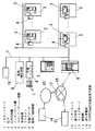
図1は本発明の一実施形態のシステム構成を示しており、図示するシステムを設置する集合住宅ではIP(インターネットプロトコル)ネットワーク1が敷設され、このIPネットワーク1に対して各住戸2に設置されている住宅情報盤3を接続するとともに各住戸2のドアホン4…を住宅情報盤3を通じて接続している。
【0016】
同様に集合住宅の玄関に設置されているロビーインターホン装置5、管理人室に設置される管理装置6、共用部の監視用TVカメラ7…の映像信号をIPネットワーク1上に送出するための映像アダプタ8、共用部であるエレベータ内の監視とエレベータ内から通話を行うための監視/通話装置9、共用部に設ける共用部内固定設置型音声装置15を夫々IPネットワーク1に接続している。これらの監視/通話装置9、共用部に設ける共用部内固定設置型音声装置15は請求項6に係る発明の音声装置に対応するものである。
【0017】
上記IPネットワーク1に接続される各機器にはローカルのIPアドレスが付与されて、音声、映像、情報を夫々に適応したIPを用いて伝送することができるようになっており、音声データの伝送にはVoIPが用いられる。
【0018】
そして管理装置6はルータ機能を備え、CATV(ケーブルテレビ回線)網、ISDN(Integrated Services Digital Network)、ADSL等のxDSL(x Digtal SubscriberLine)や、モデムを介する電話回線等の公衆網や専用回線を介してインターネット10に接続し、該インターネット10を介して他の集合住宅11のIPネットワークとの間で適宜のIPによる情報通信を可能とするとともに、インターネット10上のVoIPサーバ12を通じて加入者電話網13の加入者電話機14との間でのVoIPによる通話網を構築するようになっている。
【0019】
ここで図2は住宅情報盤3の概略構成を示しており、住宅情報盤3全体の統御を行うためのCPUユニット30,インターホン31,モニタTV32、集合住宅内のIPネットワーク1に接続するためのIPインターフェース33と、住戸間通話や、他の集合住宅の住戸内の住宅情報盤若しくはインターネット電話更には加入者電話網13上の加入者電話機14を呼び出すためのテンキーを含む入力操作部34等を備えている。
【0020】
そして各住戸の住宅情報盤3にはローカルのIPアドレスが付与されるとともに、IPアドレスに対応付けしたインターホン31用の呼び出し番号が設定されている。これらのCPUユニット30内の記憶部には自己IPアドレスを記憶保持するとともに、同一集合住戸の各住戸2の住宅情報盤3や管理装置6に具備している後述するインターホン61、相互間で通話系統が連係される他の集合住宅11の住戸2に設置されている住宅情報盤3のIPアドレスと該IPアドレスに対応して割り当てている呼び出し番号の対応関係を格納したテーブルを格納している。
【0021】
CPUユニット30は住宅情報盤3を統御するものであって、防犯、防災等住戸に設置されている各種センサ35からの検知信号を取り込んで警報器36より警報を発生させたり、モニタTV32に警報表示を行うとともに、IPインターフェース33とIPネットワーク1を通じて警報情報や、入力操作部34の操作でセットされる留守録のセット情報を管理装置6へIPにより送出する機能を備え、またインターホン31のオフフック/オンフックを監視し、オフフックされた状態で入力操作部34から呼び出し番号が入力された際に、当該呼び出し番号に対応するIPアドレスを上記記憶部より読み出し、宛先IPアドレスをIPインターフェース33に送る番号−IPアドレス変換機能を備えている。
【0022】
また加入者電話14に対する通話指示の場合には、VoIPサーバ12のIPアドレス及び呼び出し先電話番号をIPインターフェース33に送出するデータ処理機能をCPUユニット30は備えている。また住宅情報盤3に割り当てられているIPアドレスに対応した着信要求データがIPインターフェース31を通じて受信されると、起動してスピーカ37より着信音を報知させるリンガ発生機能と、その後インターホン31がオフフックされたことが検知されると着信要求先IPアドレスに対する通話路の形成を知らせたり、また話し中の場合にはビジーステータスで応答して着信拒否を着信要求先へ知らせる機能等を備えている。
【0023】
インターホン31は、送話器31aと、受話器31bと、アンプ31cを介して入力が送話器31aに接続されたA/D変換器31dと、アンプ31eを介して受話器31bに出力が接続されたD/A変換器31fとを備え、オフフック/オンフックの信号をCPUユニット30に送るとともに、A/D変換器31dの入力、D/A変換器31fの出力をIPインターフェース33内の音声復号化伸張部33a、音声符号化圧縮部33bに接続してある。
【0024】
IPインターフェース33は、通話経路形成時に、IPネットワーク1上に送出されている所定IPのパケットのヘッダの宛先が自己機器のIPアドレスであって、VoIPであれば、パケットを取り込んで音声復号化伸張処理を行って音声データを取り出し、D/A変換器31fによりD/A変換後、アンプ31eを通じて受話器31aに送る機能と、送話器31bから入力されアンプ31cを介してA/D変換器31dを通じて音声データが入力されると、音声データを音声符号化圧縮部33bにより圧縮符号化してパケット化するとともに通話先のIPアドレスを宛先としてヘッダに付し、VoIPによりIPネットワーク1上に送出する機能を有する。
【0025】
またIPインターフェース33は、IPネットワーク1上に送出されている所定IPのパケットのヘッダの宛先が自己のIPアドレスであって、送られてくるパケットの内容が画像データであれば画像処理部38へ送出する機能を備え、画像処理部38は送られてきた画像データを復号伸張化した後アナログの画像信号に変換してモニタTV32へ送り出し、モニタTV32で映し出させるようになっている。この画像データは当該住戸2のドアホン4に設けられたTVカメラ42の画像や、ロビーインターホン5に設けられたTVカメラ52の画像に対応する。
【0026】
さらにIPインターフェース33は、CPUユニット30の番号−IPアドレス変換機能を通じて通話先のIPアドレスが与えられると、着信要求データをパケット化した上でIPアドレスを宛先情報としてヘッダに付し、IPネットワーク1上に送出し、宛先から通話路確立を示すデータが送られてくると、CPUユニット30の制御の下で、上述したインターホン31に対する音声データの処理を行う。
【0027】
住戸2に備わっているドアホン4は、図2に示すようにCPUユニット40と、通話入出力部41と、TVカメラ42と、IPインターフェース43と、画像処理部44と、呼び出し釦45とで構成され、インターホン通話の処理機能は住宅情報盤3と同じとなっており、CPUユニット40は呼び出し釦45が操作されると、番号−IPアドレス変換機能により、予め登録されている当該住戸2の住宅情報盤3のIPアドレスをIPインターフェース43に与えるようになっている。IPインターフェース43は、CPUユニット40の番号−IPアドレス変換機能を通じて通話先のIPアドレスが与えられると、着信要求データをパケット化した上でIPアドレスを宛先としてヘッダに付して、IPネットワーク1上に送出し、着信要求先、この場合当該住戸2の住宅情報盤3から通話路確立を示すデータが送られてくると、CPUユニット40の制御の下で通話入出力部41に対する音声通話の処理を開始するようなっている。通話入出力部41はインターホン31と同様に送話器41a、アンプ41c、A/D変換器41d、受話器41b、アンプ41e、D/A変換器41fからなり、IPインターフェース43は、音声復号化伸張機能(図示せず)によりVoIPにより送られてくるパケット化された音声データを復号化して通話入出力部41へ、また通話入出力部41から入力される音声データを音声符号化圧縮機能により圧縮符号化してVoIPによりIPネットワーク1上に送出する。
【0028】
また通話路が形成されると、CPUユニット40は画像処理部44を動作させてTVカメラ42がとらえた映像のデータを画像処理部44に取り込ませ、データを圧縮符号化した後、IPインターフェース43によりパケット化して画像用のIPを用いて当該住戸2の住宅情報盤3のIPアドレスに対してIPネットワーク1を通じて送出させるようになっており、この画像データは上述したように住宅情報盤3で伸張復号化されてモニタTV32により映し出される。
【0029】
以上のように住戸2の住宅情報盤1とドアホン5とはIPネットワーク1を介して接続され、従来の住宅情報盤1とドアホン5との関係のように来訪者との通話や来訪者の姿のモニタが行えるのである。
【0030】
ロビーインターホン装置5の構成は、図3に示すようにCPUユニット50と、インターホン51と、TVカメラ52と、IPインターフェース53と、入力操作部54と、画像処理部55とで構成されている。このロビーインターホン装置5は住宅情報盤3と同様に入力操作部54によって訪問先の住戸の番号が入力されるとCPUユニット50の番号−IPアドレス変換機能により当該番号を、当該番号に対応する住戸2の住宅情報盤3に与えられているIPアドレスに変換し、IPインターフェース53に宛先情報として出力するようになっている。IPインターフェース53は通話先のIPアドレスが与えられると、着信要求データをパケット化した上でIPアドレスを宛先としてヘッダに付し、IPネットワーク1上に送出し、着信要求先の住戸2の住宅情報盤3から通話路確立を示すデータが送られてくると、CPUユニット50の制御の下でインターホン51に対する音声通話の処理を開始する。インターホン51はインターホン31と同様に送話器51a、アンプ51c、A/D変換器51d、受話器51b、アンプ51e、D/A変換器51fからなり、IPインターフェース53は、音声復号化伸張機能(図示せず)によりVoIPにより送られてくるパケット化された音声データを復号化してインターホン51へ、またインターホン51から入力される音声データを圧縮符号化機能(図示せず)により圧縮符号化してVoIPによりIPネットワーク1上に送出する。
【0031】
また音声通話路が形成されると、CPUユニット50は画像処理部54を動作させてTVカメラ52がとらえた映像のデータを画像処理部54に取り込んで、画像データを圧縮符号化した後、IPインターフェース53によりパケット化し、画像に対応するIPにより通報先の住戸2の住宅情報盤3のIPアドレスに対してIPネットワーク1を通じて送出させるようになっており、この画像データは上述したように住宅情報盤3で伸張復号化されてモニタTV32により映し出される。勿論管理人室に対する呼び出し時には通話相手が管理装置6のインターホン61となる。
【0032】
管理装置6の構成は、図4に示すようにCPUユニット60と、インターホン61と、モニタTV62と、IPインターフェース63と、入力操作部64と、画像処理部65と、ルータ66と、留守録部67と、警報監視部68とで構成されている。
【0033】
この管理装置6のCPUユニット60の番号−IPアドレス変換機能には各住戸2の住宅情報盤5は勿論のこと、ロビーインターホン装置5,エレベータ内の監視/通話装置9、他の集合住宅11の住戸2の住宅情報盤5、共用部内固定設置型音声装置15に割り当てている番号と、IPアドレスとの関係テーブルを備え、夫々に備わっているインターホンや通話機能を呼び出すことができるのは勿論のこと、一斉呼び出しの操作指示があると、当該集合住宅内の各住戸2の住宅情報盤3のインターホン31に対するIPアドレスを順次抽出するとともに共用部内固定設置型音声装置15のIPアドレスを抽出する機能を備えている。
【0034】
IPインターフェース63は通話先のIPアドレスが与えられると、着信要求データをパケット化した上でIPアドレスを宛先としてヘッダに付し、IPネットワーク1上に送出し、着信要求先の住戸2の住宅情報盤3等から通話路確立を示すデータが送られてくると、CPUユニット60の制御の下でインターホン61に対する音声通話の処理を開始する。インターホン61はインターホン61と同様に送話器61a、アンプ61c、A/D変換器61d、受話器61b、アンプ61e、D/A変換器61fからなり、IPインターフェース63は、音声復号化伸張機能(図示せず)によりVoIPにより送られてくるパケット化された音声データを復号化してインターホン61へ、またインターホン61から入力される音声データを圧縮符号化機能(図示せず)により圧縮符号化してVoIPによりIPネットワーク1上に送出する機能を備えている。
【0035】
またIPインターフェース63は、IPネットワーク1上に送出されている所定IPのパケットのヘッダの宛先が自己機器のIPアドレスであって、送られてくるパケットの内容が画像データであれば画像処理部65へ送出する機能を備え、画像処理部65は送られてきた画像データを復号伸張化した後、アナログの画像信号に変換して、モニタTV62へ送り出し、モニタTV62に映し出すようになっている。この画像データは当該住戸2のドアホン4に設けられたTVカメラ40の画像や、ロビーインターホン5に設けられたTVカメラ50、更にエレベータ内の監視/通話装置9に設けられているTVカメラや共用部に設けられたTVカメラ7の画像に対応する。ルータ66は当該集合住宅内のIPネットワーク1と、外部のインターネット10とを接続するためのものであり、また内部には住戸2の住宅情報盤3から外部への通信履歴を蓄積する履歴蓄積部を備え、外部通信に対する施設利用代の課金するための情報として使用するようなっている。
【0036】
留守録部67は、各住戸2の住宅情報盤3から留守録セット情報が情報伝送に対応するIPにより送られてくると、CPUユニット60の制御の下で機能するようになっている。そして、来訪者がロビーインターホン装置5を通じて留守録セットを行った当該住戸2の住宅情報盤3のインターホン31に対する呼び出し操作があって当該住宅情報盤3のIPアドレスに対する宛先をヘッダに付したパケットがIPネットワーク1上に送出されたことを、CPUユニット60がIPインターフェース63を通じて検知すると、CPUユニット60の制御の下でロビーインターホン装置5のインターホン51との間で通話路を形成し、留守録部67内のメッセージ登録部67aから当該住戸2の住人が留守である旨と、録音開始のタイミングを知らせる音声メッセージをVoIPによりロビーインターホン装置5に対してへ送出し、VoIPによりIPインターフェース63を通じてロビーインターホン装置5のインターホン51からの音声データが取り込まれると、留守録部67内の録音部に音声データを記録するようになっている。この記録された音声データは、留守録セットを行った住戸2の住宅情報盤3のインターホン31がオフフックされると、CPUユニット30の制御の下で自動的に管理装置6のIPアドレスを宛先としてヘッダに付し、留守録再生指示のデータが書き込まれたパケットを情報伝送に対応するIPによりIPインターフェース33を通じてIPネットワーク1に送出するようになっている。管理装置6のCPUユニット60はIPインターフェース63を通じて留守録再生指示のデータを受け取ると、当該住戸2の住宅情報盤3のインターホン31との通話経路を形成し、留守録部67の録音部に記録している当該住戸2宛の音声データを読み出し、IPインターフェース63を介してVoIPによりIPネットワーク1上に送出するとともに、留守録セット状態をリセットする。ネットワーク1上に送出されたVoIPによる音声データは当該住戸2の住宅情報盤3のIPインターフェース33を通じてインターホン31の受話器31bを介して聞こえ、住人は来訪者のメッセージを受け取ることができることになる。
【0037】
警報監視部68は住戸2の住宅情報盤3からIPネットワーク1を通じて情報伝送に対応するIPにより管理装置6へ警報情報が送られてくると、CPUユニット60の制御の下で、警報情報の内容や発報した住宅2の情報をモニタTV62に表示するとともに警報を発し、管理人に住戸2に異常発生があったことを知らせるようになっている。管理人はこの警報と情報とにより当該住戸2に対する確認のためにインターホン61による呼び出し通話や、住戸2へ出向き、その結果に基づいて異常発生時の処理を行うことができる。また共用部に設けた共用部内固定設置型音声装置15に対してIPネットワーク1を通じてVoIPにより放送音声データを送り一斉放送を行うこともできる。
【0038】
尚図中69は、着信音を報知させるためのスピーカであり、CPUユニット60のリング発生機能により制御される。
【0039】
尚監視/通話装置9は、呼び出し先が管理装置6のインターホン61である点でドアホン5と相違するが、ハードウェア的な構成はドアホン5と同じであるので、構成の図示と説明は省略する。
【0040】
また共用部のTVカメラ7が撮像する画像は、映像アダプタ8によって圧縮符号化されてパッケット化されIPによりIPネットワーク1上を通じて管理装置6に対して常時或いは定期的に送られ、管理装置6に設けたモニタTV62に映し出されるようになっている。
【0041】
而して上述のように構成した本実施形態の集合住宅用通信システムは、ロビーインターホン装置5と住戸2の住宅情報盤3のインターホン31との間、ロビーインターホン装置5と管理装置6のインターホン61との間、住戸2の住宅情報盤3のインターホン31と管理装置6のインターホン61との間の通話は勿論のこと、各住戸2の住宅情報盤3のインターホン31同士の通話経路を同じIPネットワーク1を通じて構築でき、VoIPを用いて双方向に音声データを送ることにより、従来のように通話路形成時の線路切り替えの制御などを必要とせず、更に電話網13に接続されている加入者電話14との間の通話も集合住宅内のIPネットワーク1を通じて行うこともできる。
【0042】
更に警報情報や画像情報等の情報も情報伝送に対応するIPによってIPネットワーク1を通じて伝送することができるため、特別な監視制御のための伝送制御を行う必要がなくなる。また住戸2の戸数の増減に対してもIPアドレスとこれに対応する呼び出しのための番号の割り当てを行うことと、番号−IPアドレス変換機能に持たせる関係テーブルの変更のみで簡単に対処できることになる。
【0043】
【発明の効果】
請求項1の発明では、集合住宅の共用部に設置されるロビーインターホン装置と、集合住宅内の各住戸に設置されるインターホンを具備した住宅情報盤と、ロビーインターホン装置及び各住戸の住宅情報盤を接続したIPネットワークを少なくとも備え、ロビーインターホン装置及び各々の住宅情報盤にVoIPによる通話処理機能を設け、ロビーインターホン装置と住宅情報盤のインターホンとの間若しくは各々の住宅情報盤のインターホン間の通話をVoIPにて行い、IPネットワークと同じ通信方式による通信が行われ複数のIPネットワークが接続可能な第1の公衆網とIPネットワークと異なる通信方式による通信が行われる第2の公衆網とを接続するVoIPサーバを備え、IPネットワークを第1の公衆網に接続し、第1の公衆網を介して第2の公衆網に接続された通話機器と、ロビーインターホン装置若しくは住宅情報盤のインターホンとの間で通話可能とし、住宅情報盤に設けた留守設定手段によって留守設定が為されている住宅に対する呼び出しがあると、起動して呼び出し側に対して留守録状態であることを知らせ且つ呼び出し側の音声データを記録する留守録機能を備え、IPネットワークに接続された管理装置を具備したので、共通のIPネットワークを利用して線路の切り替え無く、通話路を構築することができ、住戸数に関わりなく配線が簡単になる上に、線路切り替えの制御のための構成を必要とせず、システムコストも安価となり、また住戸の住宅情報盤のインターホン同士の通話もできるという効果がある。さらに、住戸の住人の留守中に来訪者が有った場合に、その来訪者に留守であることを告げることと、来訪者のメッセージを後で聞くことができる。
【0044】
また請求項1の発明では、他の集合住宅の住戸の住宅情報盤のインターホンとの間の通話や、VoIPゲートウェアを介して電話網に接続された加入者電話との通話も可能となる。
【0045】
請求項2の発明では、請求項1の発明において、上記ロビーインターホン装置及び各住宅情報盤に、固有の呼び出し番号及び対応するIPアドレスを割り当てるとともに、通話相手先の呼び出し時に通話相手先の呼び出し番号を入力する入力手段と、該入力手段から入力された相手先番号から対応するIPアドレスに変換する番号−IPアドレス変換手段を備えたので、IPアドレスの代わりに取り扱い易い番号により、加入者電話でのダイヤル操作と同様な感覚で呼び出し操作ができる。
【0046】
請求項3の発明では、請求項1又は2の何れかの発明において、上記ロビーインターホン装置にTVカメラを具備しているので、来訪者を画像によってモニタすることが可能となる。
【0047】
請求項4の発明では、請求項1乃至3の何れか記載の発明において、上記住戸には、VoIP処理機能を有し且つ上記IPネットワークに接続されたドアホンを設けてあるので、ドアホンと住宅情報盤との接続配線が簡単になる。
【0048】
請求項5の発明では、請求項4の発明において、上記ドアホンにTVカメラを具備しているので、来訪者を画像によってモニタすることが可能となる。
【0049】
請求項6の発明では、請求項1乃至5の何れかの発明において、上記集合住宅の共用部に、VoIP処理機能を有し、上記IPネットワークに接続された音声装置を設置しているので、共用部の音声装置に対する音声通信の配線も共通のIPネットワークを使用することができ、この音声装置に対する配線も簡単となる。
【0051】
請求項7の発明では、請求項1乃至6の何れかの発明において、上記管理装置には各住戸の通話履歴を保存する履歴保存機能を備えているので、保存履歴を各住戸のシステム利用に伴う課金などの資料として利用することができる。
【図面の簡単な説明】
【図1】本発明の一実施形態のシステム構成図である。
【図2】同上の住戸の住宅情報盤及びインターホン子機の構成図である。
【図3】同上のロビーインターホン装置の構成図である。
【図4】同上の管理装置の構成図である。
【符号の説明】
1 IPネットワーク
2 住戸
3 住宅情報盤
4 インターホン子機
5 ロビーインターホン装置
6 管理装置
7 TVカメラ
8 映像アダプタ
9 監視/通話装置
10 インターネット
11 集合住宅
12 VoIPサーバ
13 電話網
14 加入者電話
15 共用部内固定設置型音声装置[0001]
BACKGROUND OF THE INVENTION
The present invention relates to a communication system for an apartment house installed in an apartment house such as an apartment.
[0002]
[Prior art]
Conventional communication systems for collective housing generally include a lobby interphone device and an interphone attached to a housing information panel provided in each dwelling unit, or an interphone of a management device provided in a manager's room, A telephone system for making a call with the intercom of the housing information panel of the dwelling unit, and a TV camera image attached to the lobby intercom device for monitoring the monitor TV of the housing information panel of the dwelling unit or the monitor TV of the management device It is constructed with video transmission lines and information transmission lines for transmitting alarm information to the management device in response to detection of sensors connected to the housing information board. Line switching control was performed.
[0003]
[Problems to be solved by the invention]
In the conventional communication system for collective housing as described above, a configuration for wiring and switching control according to each system is required, and intercoms of housing information panels provided in dwelling units in the same collective housing are used. When a call cannot be made and a call is necessary, the call is made between subscriber telephones using a telephone network in the same manner as a call with the outside.
[0004]
The present invention has been made in view of the above points. A communication path can be formed through a common IP network regardless of the number of dwelling units. In addition to simple wiring, control of line switching and the like is possible. It is an object of the present invention to provide a communication system for collective housing, which requires no system configuration, has a low system cost, and can communicate with each other using an intercom on a housing information panel.
[0005]
[Means for Solving the Problems]
In order to achieve the above-mentioned object, according to the invention of
[0007]
Claim2In the invention of claim1In the invention, an input means for assigning a unique call number and a corresponding IP address to the lobby intercom device and each house information panel, and inputting the call number of the call partner when calling the call partner, and the input means And a number-IP address converting means for converting the destination number input from 1 to the corresponding IP address.
[0008]
Claim3In the invention of claim1 or 2In any one of the inventions, the lobby intercom apparatus includes a TV camera.
[0009]
Claim4In the present invention, claims 1 to3In any one of the inventions, the dwelling unit is provided with a door phone having a VoIP processing function and connected to the IP network.
[0010]
Claim5In the invention of claim4In the present invention, the door phone is provided with a TV camera.
[0011]
Claim6In the present invention, claims 1 to5In any one of the inventions, an audio device having a VoIP processing function and connected to the IP network is installed in a common part of the apartment house.
[0013]
Claim7In the invention of claimAny one of 1-6According to the invention, the management device is provided with a history storage function for storing a call history of each dwelling unit.
[0014]
Embodiment
Embodiments of the present invention will be described below.
[0015]
FIG. 1 shows a system configuration of an embodiment of the present invention. An IP (Internet Protocol)
[0016]
Similarly, a video for sending video signals from the
[0017]
Each device connected to the
[0018]
The
[0019]
Here, FIG. 2 shows a schematic configuration of the
[0020]
A local IP address is assigned to the
[0021]
The
[0022]
In the case of a call instruction to the
[0023]
The
[0024]
The
[0025]
Further, the
[0026]
Further, when the IP address of the call destination is given through the number-to-IP address conversion function of the
[0027]
As shown in FIG. 2, the
[0028]
When the communication path is formed, the
[0029]
As described above, the
[0030]
As shown in FIG. 3, the
[0031]
When the voice communication path is formed, the
[0032]
As shown in FIG. 4, the configuration of the
[0033]
The number-IP address conversion function of the
[0034]
When the IP address of the call destination is given, the
[0035]
Further, the
[0036]
The answering machine 67 functions under the control of the
[0037]
When alarm information is sent from the
[0038]
In the figure,
[0039]
The monitoring /
[0040]
An image captured by the
[0041]
Thus, the communication system for collective housing of the present embodiment configured as described above is provided between the
[0042]
Furthermore, since information such as alarm information and image information can be transmitted through the
[0043]
【The invention's effect】
According to the first aspect of the present invention, a lobby intercom device installed in a common part of an apartment house, a housing information board equipped with an interphone installed in each dwelling unit in the apartment house, a lobby intercom apparatus, and a housing information board of each dwelling unit At least an IP network connected to the lobby intercom device andEachA VoIP call processing function is provided on the home information board, between the lobby intercom device and the home information board intercom orEachA call between intercoms on a housing information panel is performed by VoIP, communication is performed using the same communication method as the IP network, and communication is performed using a communication method different from the IP network and the first public network to which a plurality of IP networks can be connected. A VoIP server for connecting to the second public network, connecting the IP network to the first public network,FirstIt is possible to make a call between a telephone device connected to the second public network via the public network and the intercom of the lobby intercom device or the housing information panel.When there is a call to a house for which an absence setting has been made by an absence setting means provided on the house information board, it is activated to notify the calling side that it is in an absence recording state and record the voice data of the calling side It has an answering machine function and a management device connected to the IP network.Therefore, it is possible to construct a communication path without switching lines using a common IP network, and the wiring is simple regardless of the number of units, and a configuration for controlling line switching is not required. As a result, the system cost can be reduced, and the intercom on the housing information panel of the dwelling unit can be used for communication.Furthermore, if there is a visitor while the resident of the dwelling unit is away, the visitor can be told that he / she is away and the message of the visitor can be heard later.
[0044]
In the invention of
[0045]
Claim2In the invention of claim1In the invention, an input means for assigning a unique call number and a corresponding IP address to the lobby intercom device and each house information panel, and inputting the call number of the call partner when calling the call partner, and the input means The number-IP address conversion means for converting the destination number input from the IP address into the corresponding IP address is provided, so that the number can be handled easily instead of the IP address, and the call operation can be performed in the same manner as the dial operation on the subscriber telephone. Can do.
[0046]
Claim3In the invention of claim1 or 2In any one of the inventions, since the lobby intercom apparatus is equipped with a TV camera, it is possible to monitor visitors with images.
[0047]
Claim4In the present invention, claims 1 to3In any of the inventions described above, since the dwelling unit is provided with a doorphone having a VoIP processing function and connected to the IP network, connection wiring between the doorphone and the house information panel is simplified.
[0048]
Claim5In the invention of claim4In this invention, since the door phone is equipped with a TV camera, it is possible to monitor the visitors with images.
[0049]
Claim6In the present invention, claims 1 to5In any of the inventions, since the voice device having the VoIP processing function and connected to the IP network is installed in the common part of the apartment house, the voice communication wiring for the voice device of the common part is also common. The IP network can be used, and wiring for the audio device is also simplified.
[0051]
Claim7In the invention of claimAny one of 1-6In the present invention, since the management device has a history storage function for storing the call history of each dwelling unit, the saved history can be used as materials such as billing associated with the system use of each dwelling unit.
[Brief description of the drawings]
FIG. 1 is a system configuration diagram of an embodiment of the present invention.
FIG. 2 is a configuration diagram of a housing information panel and an intercom handset of the same dwelling unit.
FIG. 3 is a configuration diagram of the lobby intercom apparatus of the above.
FIG. 4 is a configuration diagram of the management apparatus of the above.
[Explanation of symbols]
1 IP network
2 dwelling units
3 housing information board
4 Interphone cordless handset
5 lobby intercom equipment
6 management devices
7 TV camera
8 Video adapter
9 Monitoring / calling equipment
10 Internet
11 apartment houses
12 VoIP server
13 Telephone network
14 Subscriber telephone
15 Fixed installation type audio equipment in common area
Claims (7)
前記IPネットワークと同じ通信方式による通信が行われ複数の前記IPネットワークが接続可能な第1の公衆網と前記IPネットワークと異なる通信方式による通信が行われる第2の公衆網とを接続するVoIPサーバを備え、
前記IPネットワークを前記第1の公衆網に接続し、前記第1の公衆網を介して前記第2の公衆網に接続された通話機器と、前記ロビーインターホン装置若しくは前記住宅情報盤の前記インターホンとの間で通話可能とし、
前記住宅情報盤に設けた留守設定手段によって留守設定が為されている住戸に対する呼び出しがあると、起動して呼び出し側に対して留守録状態であることを知らせ且つ呼び出し側の音声データを記録する留守録機能を備え、前記IPネットワークに接続された管理装置を具備したことを特徴とする集合住宅用通信システム。And lobby intercom device installed in the shared portion of the apartment, connected and housing information panel provided with the interphone installed in each dwelling unit in said housing complex, the lobby intercom apparatus and the residential information panel of each dwelling unit IP at least a network, the lobby intercom apparatus and each of the housing information panel provided call handling function by VoIP, or between each said housing information panel of the intercom and the interphone of the lobby intercom apparatus with the housing information panel Calls between VoIP,
A VoIP server that connects a first public network in which communication is performed using the same communication method as the IP network and a plurality of the IP networks can be connected to a second public network in which communication is performed using a communication method different from the IP network. With
Connecting the IP network to the first public network, and the second call device connected to the public network via the first public network, and the interphone of the lobby interphone device or the housing information panel to allow calls between,
When there is a call to a dwelling unit for which an absence setting has been made by the absence setting means provided on the housing information board, it is activated to notify the calling side that it is in the absence recording state and record the voice data of the calling side A communication system for collective housing , comprising an answering machine function, and a management device connected to the IP network .
Priority Applications (1)
| Application Number | Priority Date | Filing Date | Title |
|---|---|---|---|
| JP2001159099A JP4965771B2 (en) | 2001-05-28 | 2001-05-28 | Communication system for collective housing |
Applications Claiming Priority (1)
| Application Number | Priority Date | Filing Date | Title |
|---|---|---|---|
| JP2001159099A JP4965771B2 (en) | 2001-05-28 | 2001-05-28 | Communication system for collective housing |
Publications (2)
| Publication Number | Publication Date |
|---|---|
| JP2002354133A JP2002354133A (en) | 2002-12-06 |
| JP4965771B2 true JP4965771B2 (en) | 2012-07-04 |
Family
ID=19002739
Family Applications (1)
| Application Number | Title | Priority Date | Filing Date |
|---|---|---|---|
| JP2001159099A Expired - Fee Related JP4965771B2 (en) | 2001-05-28 | 2001-05-28 | Communication system for collective housing |
Country Status (1)
| Country | Link |
|---|---|
| JP (1) | JP4965771B2 (en) |
Families Citing this family (10)
| Publication number | Priority date | Publication date | Assignee | Title |
|---|---|---|---|---|
| JP3937799B2 (en) * | 2001-10-26 | 2007-06-27 | 松下電工株式会社 | On-premises communication system |
| JP2004213218A (en) * | 2002-12-27 | 2004-07-29 | Nec Corp | Facility collective management center device and method |
| KR100685813B1 (en) * | 2004-09-16 | 2007-02-23 | 주식회사 캡스 | Apparatus for controlling door using server pc and camera and interphone and method thereof |
| JP4685576B2 (en) * | 2005-09-29 | 2011-05-18 | アイホン株式会社 | Intercom system |
| JP5000141B2 (en) * | 2006-01-26 | 2012-08-15 | 三菱電機株式会社 | Elevator remote monitoring system |
| JP2009296034A (en) * | 2008-06-02 | 2009-12-17 | Tietech Co Ltd | Interphone system in apartment house |
| JP5302023B2 (en) * | 2009-01-28 | 2013-10-02 | アイホン株式会社 | Intercom system |
| JP2010178072A (en) * | 2009-01-29 | 2010-08-12 | Panasonic Electric Works Co Ltd | Apartment intercom system |
| JP2014229915A (en) * | 2013-05-17 | 2014-12-08 | アイホン株式会社 | Intercom system |
| JP7242384B2 (en) * | 2019-03-29 | 2023-03-20 | アイホン株式会社 | Housing intercom system |
Family Cites Families (11)
| Publication number | Priority date | Publication date | Assignee | Title |
|---|---|---|---|---|
| JPH09121252A (en) * | 1995-10-25 | 1997-05-06 | Aiphone Co Ltd | Multiple dwelling house interphone device |
| JPH09163462A (en) * | 1995-12-12 | 1997-06-20 | Inmeru:Kk | Multiple dwelling house information processing system |
| JPH10229413A (en) * | 1997-02-17 | 1998-08-25 | Shimizu Corp | Housing area intra-net system |
| JPH10327256A (en) * | 1997-05-23 | 1998-12-08 | N T T Facilities:Kk | Interphone system adaptable for remote operation |
| JPH11275070A (en) * | 1998-03-19 | 1999-10-08 | Sony Corp | Connection device |
| JPH11284660A (en) * | 1998-03-26 | 1999-10-15 | Mc Corporation:Kk | Sectioned building equipped with connection terminal for information equipment |
| JP4199371B2 (en) * | 1998-10-02 | 2008-12-17 | アイホン株式会社 | Apartment house intercom device |
| JP4317614B2 (en) * | 1999-06-30 | 2009-08-19 | 株式会社ナカヨ通信機 | Terminal adapter with doorphone function |
| JP4151184B2 (en) * | 1999-12-22 | 2008-09-17 | 松下電工株式会社 | Regional service network |
| JP3425109B2 (en) * | 1999-12-27 | 2003-07-07 | 鹿島建設株式会社 | Network system for apartment houses |
| JP2000196601A (en) * | 2000-03-06 | 2000-07-14 | ▼高▲木 祥澄 | Lan system in the same area |
-
2001
- 2001-05-28 JP JP2001159099A patent/JP4965771B2/en not_active Expired - Fee Related
Also Published As
| Publication number | Publication date |
|---|---|
| JP2002354133A (en) | 2002-12-06 |
Similar Documents
| Publication | Publication Date | Title |
|---|---|---|
| US6529230B1 (en) | Security and fire control system | |
| JP2002125059A (en) | Interphone system and interphone system transfer method for multiple dwelling house | |
| WO2007104212A1 (en) | Network terminal door bell device, system and method | |
| JP2007274177A (en) | Interphone system | |
| JP4965771B2 (en) | Communication system for collective housing | |
| KR100647819B1 (en) | System and method for monitoring home using the IP phone | |
| JP5291288B2 (en) | Intercom system | |
| JP3937799B2 (en) | On-premises communication system | |
| KR20050014357A (en) | Home networking system connected with home automation machine using home gateway and computer | |
| KR20010019901A (en) | Doorphone system capable of taking over the telephone with a visitor during my absence | |
| JP2006222887A (en) | Dwelling machine of intercom system for multiple dwelling house and intercom system for multiple dwelling house | |
| JP3726549B2 (en) | Door phone cordless handset adapter | |
| KR20010093604A (en) | A cyber phone protection system using internet network system | |
| KR20070010635A (en) | System and method for advertisement and security monitoring service using the ip based private branch exchange | |
| JP2003032375A (en) | Interphone system | |
| JP2005260359A (en) | Monitoring/speech system for multiple dwelling house | |
| KR20020013646A (en) | Internet call-bell system and its service method | |
| KR20020009002A (en) | Internet video phone | |
| JP3727953B2 (en) | Terminal apparatus and control method thereof | |
| KR101131904B1 (en) | REAL TIME SECURITY SYSTEM USING VoIP | |
| KR20010069630A (en) | The method and Security and visitor communication systems based on IP network | |
| JP2004072441A (en) | Ip camera telephone device with image display function | |
| JP2005294968A (en) | Intercom system for condominium and security system for condominium having auto lock function | |
| KR20080049968A (en) | Video Phone System and Its Method of Apartment Housing Using IP Telephone Network | |
| KR200454715Y1 (en) | Unmanned security system including VoIP joint hall and DTMF receiver. |
Legal Events
| Date | Code | Title | Description |
|---|---|---|---|
| A621 | Written request for application examination |
Free format text: JAPANESE INTERMEDIATE CODE: A621 Effective date: 20071221 |
|
| A977 | Report on retrieval |
Free format text: JAPANESE INTERMEDIATE CODE: A971007 Effective date: 20091218 |
|
| RD04 | Notification of resignation of power of attorney |
Free format text: JAPANESE INTERMEDIATE CODE: A7424 Effective date: 20100622 |
|
| A131 | Notification of reasons for refusal |
Free format text: JAPANESE INTERMEDIATE CODE: A131 Effective date: 20100907 |
|
| A521 | Written amendment |
Free format text: JAPANESE INTERMEDIATE CODE: A523 Effective date: 20101108 |
|
| A02 | Decision of refusal |
Free format text: JAPANESE INTERMEDIATE CODE: A02 Effective date: 20111004 |
|
| A521 | Written amendment |
Free format text: JAPANESE INTERMEDIATE CODE: A523 Effective date: 20111205 |
|
| A911 | Transfer to examiner for re-examination before appeal (zenchi) |
Free format text: JAPANESE INTERMEDIATE CODE: A911 Effective date: 20111212 |
|
| A711 | Notification of change in applicant |
Free format text: JAPANESE INTERMEDIATE CODE: A712 Effective date: 20120111 |
|
| TRDD | Decision of grant or rejection written | ||
| A01 | Written decision to grant a patent or to grant a registration (utility model) |
Free format text: JAPANESE INTERMEDIATE CODE: A01 Effective date: 20120306 |
|
| A01 | Written decision to grant a patent or to grant a registration (utility model) |
Free format text: JAPANESE INTERMEDIATE CODE: A01 |
|
| A61 | First payment of annual fees (during grant procedure) |
Free format text: JAPANESE INTERMEDIATE CODE: A61 Effective date: 20120330 |
|
| R150 | Certificate of patent or registration of utility model |
Free format text: JAPANESE INTERMEDIATE CODE: R150 |
|
| FPAY | Renewal fee payment (event date is renewal date of database) |
Free format text: PAYMENT UNTIL: 20150406 Year of fee payment: 3 |
|
| LAPS | Cancellation because of no payment of annual fees |