JP4961930B2 - Telephone system and telephone control device - Google Patents
Telephone system and telephone control device Download PDFInfo
- Publication number
- JP4961930B2 JP4961930B2 JP2006267680A JP2006267680A JP4961930B2 JP 4961930 B2 JP4961930 B2 JP 4961930B2 JP 2006267680 A JP2006267680 A JP 2006267680A JP 2006267680 A JP2006267680 A JP 2006267680A JP 4961930 B2 JP4961930 B2 JP 4961930B2
- Authority
- JP
- Japan
- Prior art keywords
- telephone
- wired
- wireless
- call
- wireless telephone
- Prior art date
- Legal status (The legal status is an assumption and is not a legal conclusion. Google has not performed a legal analysis and makes no representation as to the accuracy of the status listed.)
- Active
Links
Images


Description
本発明は、電話制御技術に関し、特に、ボタン電話機(有線子機)と無線電話機とを収容した電話システムに関する。 The present invention relates to a telephone control technique, and more particularly to a telephone system that accommodates a button telephone (wired handset) and a wireless telephone.
従来より、会社や工場等において、無線電話機を利用した電話システムが用いられている(例えば、特許文献1参照。)。この無線電話機は、持ち運びできて便利であるので、近年では、ボタン電話機(有線子機)とともに無線電話機を収容した電話システムが提案されている。この電話システムでは、一人のユーザが有線子機と無線電話機の両方を所持することが可能である。この場合、例えば、自分の席には有線子機を設置しておき、席から離れるときには無線電話機を携帯することより、机にいる場合でも机から離れた場合でも電話を利用することができる。 Conventionally, a telephone system using a wireless telephone has been used in a company, a factory, or the like (for example, see Patent Document 1). Since this wireless telephone is portable and convenient, a telephone system that accommodates a wireless telephone together with a button telephone (wired handset) has recently been proposed. In this telephone system, one user can possess both a wired slave unit and a wireless telephone. In this case, for example, a wired cordless handset is installed in his / her seat, and when he / she is away from the seat, he / she can carry the telephone regardless of whether he / she is at his / her desk.
一般に、有線子機と無線電話機にはそれぞれ異なる内線番号が付与される。このため、有線子機と無線電話機とを所有するユーザは、二つの内線番号を有することになるので、このユーザに対して何れの電話番号を用いればよいのか特定するのが困難な場合がある。例えば、外線を上記ユーザの有線子機に転送しようとした場合、そのユーザが席から離れていると無線電話機に転送し直さなければならない。また、普段は有線子機から呼出を行っているがときおり無線電話機から呼出を行うような場合、上記ユーザから呼び出された相手は、発信者番号が異なるため、何れのユーザからの着信であるのか識別することが困難である。このように、従来の電話システムでは、ユーザを特定するのが困難なため、相手を混乱させてしまうことがあった。 Generally, a different extension number is assigned to each of the wired slave unit and the wireless telephone. For this reason, a user who owns a wired cordless handset and a wireless telephone has two extension numbers, so it may be difficult to specify which telephone number should be used for this user. . For example, when an outside line is to be transferred to the user's wired cordless handset, if the user is away from the seat, the user must transfer the outside line back to the wireless telephone. Also, when a call is normally made from a cordless handset, but a call is made from a wireless telephone, the other party called by the user has a different caller number, so which user is the incoming call? It is difficult to identify. As described above, in the conventional telephone system, it is difficult to specify the user, so that the other party may be confused.
そこで、本願発明は、同一のユーザにより複数の電話機が使用される場合であっても、そのユーザを特定することができる電話システムおよび電話制御装置を提供することを目的とする。 Therefore, an object of the present invention is to provide a telephone system and a telephone control device that can specify a user even when a plurality of telephones are used by the same user.
上述したような課題を解決するために、本発明にかかる電話システムは、電話回線に接続される電話制御装置と、この電話制御装置に収容された複数の電話機とを有する電話システムにおいて、電話制御装置は、電話機の呼出先を対応付けて登録した端末登録情報を記憶する記憶手段と、端末登録情報に基づいて、電話機を呼制御する呼制御手段とを有し、電話機は、有線伝送路を介して電話制御装置に接続される有線電話機と、無線伝送路を介して電話制御装置に接続される無線電話機とを含み、端末登録情報により有線電話機と対応付けられた無線電話機の状態を検出する検出手段と、この検出手段の検出結果に応じて端末管理情報を記憶手段に登録する登録手段とをさらに備え、呼制御手段は、有線電話機が呼び出されたとき、端末管理情報に基づいて、当該有線電話機と対応付けられた無線電話機を呼び出す電話システムであって、呼制御手段は、無線電話機からの発信を検出すると、この無線電話機と対応付けられた有線電話機の識別番号を相手先に送信することを特徴とする。 In order to solve the above-described problems, a telephone system according to the present invention includes a telephone control device connected to a telephone line and a telephone system having a plurality of telephones accommodated in the telephone control device. apparatus includes storage means for storing a terminal registration information registered in association with the called phone, based on the terminal registration information, and have a call control means for call control the phone, the phone, the wired transmission path Including a wired telephone connected to the telephone control device via the wireless communication path and a wireless telephone connected to the telephone control device via a wireless transmission path, and detecting the state of the wireless telephone associated with the wired telephone based on the terminal registration information Detection means, and registration means for registering terminal management information in the storage means in accordance with the detection result of the detection means, and the call control means is connected to the terminal tube when the wired telephone is called. A telephone system for calling a wireless telephone associated with the wired telephone based on the information, and when the call control means detects an outgoing call from the wireless telephone, the identification number of the wired telephone associated with the wireless telephone Is transmitted to the other party .
また、本発明にかかる電話制御装置は、電話回線に接続され、複数の電話機を収容し、電話機の呼出先を対応付けて登録した端末登録情報を記憶する記憶手段と、端末登録情報に基づいて、電話機を呼制御する呼制御手段とを有し、電話機は、有線伝送路を介して接続される有線電話機と、無線伝送路を介して接続される無線電話機とを含み、端末登録情報により有線電話機と対応付けられた無線電話機の状態を検出する検出手段と、この検出手段の検出結果に応じて端末管理情報を記憶手段に登録する登録手段とをさらに備え、呼制御手段は、有線電話機が呼び出されたとき、端末管理情報に基づいて、当該有線電話機と対応付けられた無線電話機を呼び出す電話制御装置であって、呼制御手段は、無線電話機からの発信を検出すると、この無線電話機と対応付けられた有線電話機の識別番号を相手先に送信することを特徴とする。 The telephone control device according to the present invention is connected to a telephone line, accommodates a plurality of telephones, stores terminal registration information registered in association with telephone call destinations, and based on the terminal registration information. , and a call control unit for call control the phone, the phone includes a wire telephone set connected through a wired transmission path, and a radio telephone set connected via a radio transmission path, the terminal registration information And a registration means for registering terminal management information in the storage means according to the detection result of the detection means. When a telephone is called, the telephone control device calls a wireless telephone associated with the wired telephone based on the terminal management information. When the call control means detects a call from the wireless telephone, And transmitting the identification number of the wired telephone associated with the wireless telephone to the destination.
本発明によれば、電話機の呼出先を対応付けて登録した端末登録情報に基づいて電話機の呼制御が行われるので、同一のユーザにより複数の電話機が使用される場合であっても、これらの電話機のうち何れの電話機を呼び出せばよいか特定することができるので、結果として、ユーザを確実に特定することができる。したがって、相手を混乱させるのを防ぐことができる。 According to the present invention, since the call control of the telephone is performed based on the terminal registration information registered in association with the call destination of the telephone, even when a plurality of telephones are used by the same user, Since it is possible to specify which of the telephones should be called, as a result, the user can be reliably specified. Therefore, it is possible to prevent the other party from being confused.
次に、本発明の実施の形態について図面を参照して詳細に説明する。 Next, embodiments of the present invention will be described in detail with reference to the drawings.
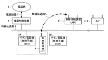
図1に示すように、本実施の形態にかかる電話システムは、電話制御装置1と、少なくとも1つのボタン電話機(有線子機)2と、少なくとも1つの無線接続装置(AP:Access Point)3と、少なくとも1つの無線電話機4とから構成されている。なお、本実施の形態においては、無線接続装置3が2つ設けられている(無線接続装置3−1,3−2)場合を例に説明する。
As shown in FIG. 1, the telephone system according to the present embodiment includes a
電話制御装置1は、公衆電話網(PSTN:Public Switched Telephone Network)、ISDN(Integrated Service Digital Network)、IP(Internet Protocol)電話網などの電話網8からの電話回線7に接続されて、電話回線7を終端制御することにより各種呼制御を行う制御装置である。
The
ボタン電話機(有線子機)2は、LAN(Local Area Network)などの内線伝送路6を介して電話制御装置1に接続されて電話制御装置1との間で各種データをやり取りすることにより、電話制御装置1の内線電話機として動作し、その内線電話機の呼に関する音声通話を行う端末装置である。
A key telephone (wired handset) 2 is connected to the
無線接続装置(AP)3,3−1,3−2は、内線伝送路6を介して電話制御装置1に接続されて、無線伝送路5を介して無線電話機4とデジタルデータ通信を行うことにより、電話制御装置1と無線電話機4との間でやり取りされる各種データを相互に通信する装置である。
The wireless connection devices (AP) 3, 3-1 and 3-2 are connected to the
無線電話機4は、無線伝送路5を介して無線接続装置3と接続されて電話制御装置1との間で各種データのやり取りをすることにより、電話制御装置1の内線電話機として動作し、その内線電話機の呼に関する音声通話を行う端末装置である。
The
本実施の形態は、電話制御装置1により、ボタン電話機(有線子機)2と無線電話機4との対応関係を示す端末登録情報を管理しておき、この端末登録情報に基づいてボタン電話機(有線子機)2と無線電話機4の呼を制御するようにしたものである。
In the present embodiment, terminal registration information indicating the correspondence between the key telephone (wired handset) 2 and the
[電話制御装置]
図2に示すように、電話制御装置1は、コンピュータで動作する通信制御装置であり、回線インターフェース部(以下、「回線I/F部」という)11と、LANインターフェース部(以下、「LANI/F部」という)12と、記憶部13と、制御部14とから構成される。
[Telephone control device]
As shown in FIG. 2, the
回線I/F部11は、電話網8からの電話回線7を終端制御する回路部であり、電話回線7について着信検出や発信などの回線制御を行う機能を有している。
The line I /
LANI/F部12は、内線伝送路6を介してデジタルデータ通信を行う回路部であり、ボタン電話機(有線子機)2や無線接続装置(AP)3と制御データや音声データをやり取りする機能を有している。
The LAN I /
記憶部13は、メモリやハードディスクなどの記憶装置からなり、制御部14での各種処理に用いる処理情報やプログラム13Pを格納する機能を有している。プログラム13Pは、回線I/F部11やLANI/F部12などの入出力インターフェース部を介して外部装置や記録媒体から読み取られ予め記憶部13へ格納される。
The
記憶部13に格納される主な処理情報としては、呼制御情報13A、端末登録情報13B、位置情報13Cなどがある。呼制御情報13Aは、電話回線7の状態や、ボタン電話機(有線子機)2や無線電話機4の動作状態を管理するための情報である。端末登録情報13Bは、電話システムのボタン電話機(有線子機)2と無線電話機4の対応関係を示す情報である。
Main processing information stored in the
図3は端末登録情報13Bの構成例であり、電話制御装置1の内線電話機に割り当てられた内線電話番号ごとに、外線や内線電話機に発信する際に相手先の端末装置に表示させる電話番号に関する表示番号と、外線や内線電話機からの着信を転送する内線電話機の電話番号に関する転送先番号と、この転送先番号の内線電話機に着信を転送するか否かを示す端末管理情報とが組として管理されている。
FIG. 3 shows an example of the configuration of the
位置情報13Cは、ボタン電話機(有線子機)2や無線接続装置3が配置された物理的な位置に関する情報である。
The
制御部14は、CPUなどのマイクロプロセッサとその周辺回路からなり、記憶部13からプログラム13Pを読み込んで実行することにより、上記ハードウェアとプログラム13Pを協働させて各種機能手段を実現する機能部である。制御部14で実現される主な機能手段としては、呼制御手段14A、検出手段14Bおよび登録手段14Cがある。
The
呼制御手段14Aは、記憶部13の呼制御情報13Aや端末登録情報13Bに基づき回線I/F部11やLANI/F部12を制御して、電話回線7の回線制御や、ボタン電話機(有線子機)2および無線電話機4の動作制御を行う機能を有している。
The
検出手段14Bは、LANI/F部12を制御して無線接続装置(AP)3が通信を行っている無線電話機4と各種情報のやり取りをすることにより、無線電話機4の電源のON/OFF状態や、無線電話機4が充電中か否かや、記憶部13の位置情報13Cに基づいてその無線電話機4の位置を検出する機能する機能を有している。
The detecting
登録手段14Cは、検出手段14Bにより検出結果に基づいて、端末登録情報13Bの端末管理情報を登録する機能を有している。
The
[登録動作]
次に、図4,図5を参照して、端末登録情報13Bにおける転送先番号の登録動作について説明する。この登録動作においては、内線電話番号が101の有線子機2Aと、内線電話番号が102の有線子機2Bと、内線電話番号が701の無線電話機4とを備えた電話システムにおいて、有線子機2Aと無線電話機4とが対応付けられる、すなわち同一のユーザによって有線子機2Aと無線電話機4と使用される場合を例に説明する。
[Registration action]
Next, with reference to FIGS. 4 and 5, the transfer destination number registration operation in the
まず、電話制御装置1の制御部14の検出手段14Bは、無線電話機4の状態を検出する。この状態としては、無線電話機4に電源が投入されているか否か、無線電話機4が充電中であるか否か、無線電話機4が有線子機2Aから離れた位置にあるか否かが挙げられる。それぞれの状態は、以下のようにして検出する。
First, the detection means 14B of the
無線電話機4に電源が投入されているか否かは、LANI/F部12を制御して、会社や工場などの所定の領域に設定された何れかのAP3−1,3−2が通信を行っている無線電話機4を検出し、この検出した無線電話機4については電源が投入されているものとして検出する。また、検出した無線電話機4と端末登録情報13Bとを比較し、端末登録情報13Bに含まれているがLANI/F部12により検出されなかった無線電話機4は、電源が投入されていないものとして検出する。なお、充電中であるか否かは、電源が投入されているか否かを検出する場合と同様、端末登録情報13Bに含まれているがLANI/F部12により検出されなかった無線電話機4を充電中であるものとして検出するようにしてもよい。
Whether or not the power of the
無線電話機4が有線子機2Aから離れた位置にあるか否かは、LANI/F部12を制御して、無線電話機4と通信を行っているAP3を検出し、位置情報13Cに基づいて当該AP3の位置を検出し、例えば有線子機2Aの位置が当該AP3により無線電話機4からの無線信号を検出可能な範囲外であるなど、当該AP3の位置が有線子機2Aから所定の距離だけ離れている場合、当該無線電話機4は有線子機2Aから離れた位置にあるものとして検出する。
Whether or not the
検出手段14Bにより無線電話機4が所定の状態(以下、「登録状態」という)にないことが検出されると、登録手段14Cは、端末登録情報13Bにおける有線子機2Aの端末管理情報を登録しない。ここで、登録状態ではないとは、例えば、無線電話機4に電源が投入されていない、無線電話機4が有線子機2Aの近くにあるなど、ユーザが有線子機2Aの近くにいる状態を表す。
When the
例えば、図4(a)に示すように、有線子機2Aと対応付けられた無線電話機4が、有線子機2Aから離れた位置にあるAP3−2により検出されない場合、登録手段14Cは、無線電話機4が登録状態にないとして、端末登録情報13Bにその無線電話機4の端末管理情報を登録しない。このとき、端末登録情報13Bには、図4(b)に示すように、有線子機2Aの内線電話番号(101)の端末管理情報のフラグが「0」となる。
For example, as shown in FIG. 4A, when the
一方、検出手段14Bにより無線電話機4が登録状態にあることが検出されると、登録手段14Cは、端末登録情報13bにその無線電話機4の端末管理情報を登録する。ここで、登録状態であるとは、無線電話機4に電源が投入されている、無線電話機4が有線子機2Aから離れているなど、ユーザが有線子機2Aから離れた位置にいる状態を表す。
On the other hand, when the
例えば、図5(a)に示すように、有線子機2Aと対応付けられた無線電話機4が、有線子機2Aから離れた位置にあるAP3−2により検出された場合、登録手段14Cは、無線電話機4が登録状態にあるとして、端末登録情報13Bにその無線電話機4の端末管理情報を登録する。すると、端末登録情報13Bには、図5(b)に示すように、転送先番号に無線電話機4の内線番号(701)が登録されている有線子機(101)の端末管理情報のフラグが「1」となる。
For example, as shown in FIG. 5A, when the
このように、本実施の形態によれば、無線電話機4の状態に応じて、端末登録情報13Bの端末管理情報が登録される、すなわち端末管理情報のフラグが変更される。
Thus, according to the present embodiment, the terminal management information of the
[着信動作]
次に、図6を参照して、本実施の形態にかかる電話システムにおける着信動作について説明する。この着信動作は、上述した登録動作と同等の構成の電話システムにおいて、有線子機2Bが有線子機2Aに対して内線呼出を行った場合を例に説明する。
[Incoming call operation]
Next, an incoming call operation in the telephone system according to the present embodiment will be described with reference to FIG. This incoming call operation will be described by taking as an example a case where the
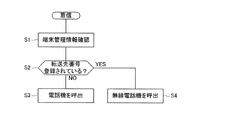
有線子機2Bが有線子機2Aに対して内線呼出を行ったことを検出すると、呼制御手段14Aは、端末登録情報13Bにより、有線子機2Aの端末管理情報を確認する(ステップS1)。
When it is detected that the
例えば図4に示すように、端末管理情報のフラグが「0」となっている場合(ステップS2:NO)、呼制御手段14Aは、有線子機2Aのスピーカから呼出音を出力させたり、有線子機2Aのディスプレイに有線子機2Bの内線番号を表示させたりすることにより、有線子機2Aに対して内線呼出を行う(ステップS3)。有線子機2Aのハンドセットがオフフックされたり、有線子機2Aの応答ボタンを押下されたりすると、呼制御手段14Aは、LANI/F部12を制御して内線伝送路6を介して有線子機2Aと有線子機2Bとの通話パスを接続する。これにより、有線子機2Aと有線子機2Bとの通話が実現される。
For example, as shown in FIG. 4, when the flag of the terminal management information is “0” (step S2: NO), the
一方、例えば図5に示すように、端末管理情報のフラグが「1」となっている場合(ステップS2:YES)、呼制御手段14Aは、無線電話機4に対して内線呼出を行う(ステップS4)。具体的には、図7に示すように、有線子機2Bにより有線子機2Aの内線番号(101)に対する内線呼出を検出すると、呼制御手段14Aは、端末登録情報13Bの端末管理情報を確認する。上述したように、端末管理情報のフラグが「1」となっていると、呼制御手段14Aは、有線子機2Aの内線番号を転送先番号に置き換える。図5に示すように、端末登録情報13Bには、有線子機2Aの転送先番号として無線電話機4の内線番号(701)が登録されているので、呼制御手段14Aは、有線子機2Aの内線番号(101)を無線電話機4の内線番号(701)に置き換え、無線電話機4に対して内線呼出を行う。これにより、無線電話機4のスピーカから呼出音が出力されたり、無線電話機4のディスプレイに有線子機2Bの内線番号が表示されたりする。このような内線呼出に対して、無線電話機4のハンドセットがオフフックされたり、無線電話機4の応答ボタンが押下されたりすると、呼制御手段14Aは、LANI/F部12を制御して内線伝送路6を介して無線電話機4と有線子機2Bとの通話パスを接続する。これにより、無線電話機4と有線子機2Bとの間の通話が実現する。
On the other hand, as shown in FIG. 5, for example, when the flag of the terminal management information is “1” (step S2: YES), the
上述したように本実施の形態によれば、一人のユーザが有線子機2Aと無線電話機4の両方を使用する場合において、端末登録情報13Bに端末管理情報が登録されていると、有線子機2Aに対して内線呼出等が行われたとき、この内線呼出が有線子機2Aの転送先番号として内線番号が登録されている無線電話機4に対して行われるので、発信者は有線子機2Aのユーザとの通話を行うことができる。このように、一人のユーザが有線子機2Aと無線電話機4の両方を使用する場合においても、そのユーザを確実に特定することができる。結果として、そのユーザを呼び出した相手が混乱することを防ぐことができる。
As described above, according to the present embodiment, when one user uses both the wired
[発信動作]
次に、図8を参照して、本実施の形態にかかる電話システムにおける発信動作について説明する。この発信動作は、上述した登録動作および着信動作と同等の構成の電話システムにおいて、無線電話機4が有線子機2Bに対して内線呼出を行った場合を例に説明する。ここで、有線子機2Aと無線電話機4とは同一のユーザに使用されるものとし、図4(b),図5(b)に示すように、無線電話機4の表示番号には有線子機2Aの内線番号が登録されているものとする。
[Outgoing action]
Next, with reference to FIG. 8, a call operation in the telephone system according to the present embodiment will be described. This outgoing call operation will be described by taking as an example a case where the
無線電話機4が有線子機2Bに対して内線呼出を行ったことを検出すると、呼制御手段14Aは、端末登録情報13Bにより、無線電話機4の表示番号を確認し(ステップS11)、無線電話機4の表示番号を取得する(ステップS12)。上述したように、有線子機2Aと無線電話機4とが対応付けられており、図4(b),図5(b)に示すように、無線電話機4の表示番号には有線子機2Aの内線番号(101)が登録されている。したがって、呼制御手段14Aは、無線電話機4の表示番号として有線子機2Aの内線番号(101)を取得する。
When detecting that the
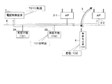
表示番号を取得すると、呼制御手段14Aは、有線子機2Bに対して内線呼出を行う際に、取得した表示番号を発信者番号として有線子機2Bに送信する(ステップS13)。具体的には、図9に示すように、無線電話機4により有線子機2Bに対する内線呼出を検出すると、呼制御手段14Aは、端末登録情報13Bを確認する。端末登録情報13Bには、無線電話機4の表示番号として有線子機2Aの内線番号(101)が登録されているので、呼制御手段14Aは、有線子機2Bに送信する発信者番号を有線子機2Aの内線番号(101)とし、有線子機2Bに対して内線呼出を行う。すると、有線子機2Bのディスプレイには、有線子機2Aの内線番号(101)が表示される。したがって、有線子機2Bのユーザは、有線子機2Aのユーザからの内線呼出であることを認識することができる。このような内線呼出に対して、有線子機2Bのハンドセットがオフフックされたり、有線子機2Bの応答ボタンが押下されたりすると、呼制御手段14Aは、LANI/F部12を制御して内線伝送路6を介して無線電話機4と有線子機2Bとの通話パスを接続する。これにより、無線電話機4と有線子機2Bとの間の通話が実現する。
When the display number is acquired, the
会社や工場等に設置される電話システムにおいて、一人のユーザが有線子機と無線電話機の両方を使用すると、同じユーザからの内線呼出の場合であっても通知される内線番号が異なるため、何れのユーザからの着信か識別することが困難であった。そこで、本実施の形態では、端末登録情報13Bにおいて無線電話機4の表示番号を有線子機2Aの内線番号と登録することにより、有線子機2Aと無線電話機4の両方を使用するユーザからの着信は、常に有線子機2Aの内線番号が通知される。このため、何れのユーザからの着信かを容易に特定することができる。結果として、そのユーザから呼び出された相手が混乱するのを防ぐことができる。
In a telephone system installed in a company, factory, etc., if one user uses both a wired cordless handset and a wireless telephone, the extension number to be notified will be different even if the extension call is made from the same user. It was difficult to identify incoming calls from other users. Therefore, in the present embodiment, by registering the display number of the
なお、本実施の形態では、一人のユーザが有線子機と無線電話機を使用する場合を例に説明したが、一人のユーザが使用する電話機は有線子機と無線電話機に限定されず、例えば、2台以上の有線子機、2台以上の有線子機と1台の無線電話機、1台の有線子機と2台以上の無線電話機、2台以上の無線電話機など、有線子機と無線子機の組み合わせや数量を適宜自由に設定することができる。 In this embodiment, a case where one user uses a wired slave unit and a wireless telephone has been described as an example. However, a telephone used by one user is not limited to a wired slave unit and a wireless telephone. For example, Two or more wired slave units, two or more wired slave units and one wireless telephone, one wired slave unit and two or more wireless telephones, two or more wireless telephones, etc. The combination and quantity of machines can be set freely as appropriate.
本発明は、無線電話機とボタン電話機とを収容した電話システムに適用することができる。 The present invention can be applied to a telephone system that accommodates a radio telephone and a button telephone.
1…電話制御装置、2,2A,2B…ボタン電話機(有線子機)、3…無線接続装置、4…無線電話機、5…無線伝送路、6…内線伝送路、7…電話回線、8…電話網、11…回線I/F部、12…LANI/F部、13…記憶部、13A…呼制御情報、13B…端末登録情報、13C…位置情報、13P…プログラム、14…制御部、14A…呼制御手段、14B…検出手段、14C…登録手段。
DESCRIPTION OF
Claims (2)
この電話制御装置に収容された複数の電話機と
を有し、
前記電話制御装置は、
前記電話機の呼出先を対応付けて登録した端末登録情報を記憶する記憶手段と、
前記端末登録情報に基づいて、前記電話機を呼制御する呼制御手段と
を有し、
前記電話機は、有線伝送路を介して前記電話制御装置に接続される有線電話機と、無線伝送路を介して前記電話制御装置に接続される無線電話機とを含み、
前記端末登録情報により前記有線電話機と対応付けられた前記無線電話機の状態を検出する検出手段と、
この検出手段の検出結果に応じて端末管理情報を前記記憶手段に登録する登録手段と
をさらに備え、
前記呼制御手段は、前記有線電話機が呼び出されたとき、前記端末管理情報に基づいて、当該有線電話機と対応付けられた前記無線電話機を呼び出す電話システムであって、
前記呼制御手段は、前記無線電話機からの発信を検出すると、この無線電話機と対応付けられた前記有線電話機の識別番号を相手先に送信する
ことを特徴とする電話システム。 A telephone control device connected to the telephone line;
Have a plurality of telephone accommodated in the telephone controller,
The telephone control device
Storage means for storing terminal registration information registered in association with a call destination of the telephone;
Based on the terminal registration information, the telephone have a call control means for call control,
The telephone includes a wired telephone connected to the telephone control apparatus via a wired transmission path, and a wireless telephone connected to the telephone control apparatus via a wireless transmission path,
Detecting means for detecting a state of the wireless telephone associated with the wired telephone by the terminal registration information;
Registration means for registering terminal management information in the storage means according to the detection result of the detection means;
Further comprising
The call control means is a telephone system for calling the wireless telephone associated with the wired telephone based on the terminal management information when the wired telephone is called,
When the call control means detects an outgoing call from the wireless telephone, the telephone control system transmits the identification number of the wired telephone associated with the wireless telephone to the other party .
前記電話機の呼出先を対応付けて登録した端末登録情報を記憶する記憶手段と、
前記端末登録情報に基づいて、前記電話機を呼制御する呼制御手段と
を有し、
前記電話機は、有線伝送路を介して接続される有線電話機と、無線伝送路を介して接続される無線電話機とを含み、
前記端末登録情報により前記有線電話機と対応付けられた前記無線電話機の状態を検出する検出手段と、
この検出手段の検出結果に応じて端末管理情報を前記記憶手段に登録する登録手段と
をさらに備え、
前記呼制御手段は、前記有線電話機が呼び出されたとき、前記端末管理情報に基づいて、当該有線電話機と対応付けられた前記無線電話機を呼び出す電話制御装置であって、
前記呼制御手段は、前記無線電話機からの発信を検出すると、この無線電話機と対応付けられた前記有線電話機の識別番号を相手先に送信する
ことを特徴とする電話制御装置。 Connected to a telephone line, accommodates multiple telephones,
Storage means for storing terminal registration information registered in association with a call destination of the telephone;
Call control means for performing call control of the telephone based on the terminal registration information;
It said telephone comprises a wired telephone set connected through a wired transmission path, and a radio telephone set connected via a radio transmission path,
Detecting means for detecting a state of the wireless telephone associated with the wired telephone by the terminal registration information;
Registration means for registering terminal management information in the storage means according to the detection result of the detection means; and
The call control means is a telephone control device that, when the wired telephone is called, calls the wireless telephone associated with the wired telephone based on the terminal management information,
When the call control means detects an outgoing call from the wireless telephone, the call control means transmits the identification number of the wired telephone associated with the wireless telephone to the other party.
Priority Applications (1)
| Application Number | Priority Date | Filing Date | Title |
|---|---|---|---|
| JP2006267680A JP4961930B2 (en) | 2006-09-29 | 2006-09-29 | Telephone system and telephone control device |
Applications Claiming Priority (1)
| Application Number | Priority Date | Filing Date | Title |
|---|---|---|---|
| JP2006267680A JP4961930B2 (en) | 2006-09-29 | 2006-09-29 | Telephone system and telephone control device |
Publications (2)
| Publication Number | Publication Date |
|---|---|
| JP2008092044A JP2008092044A (en) | 2008-04-17 |
| JP4961930B2 true JP4961930B2 (en) | 2012-06-27 |
Family
ID=39375758
Family Applications (1)
| Application Number | Title | Priority Date | Filing Date |
|---|---|---|---|
| JP2006267680A Active JP4961930B2 (en) | 2006-09-29 | 2006-09-29 | Telephone system and telephone control device |
Country Status (1)
| Country | Link |
|---|---|
| JP (1) | JP4961930B2 (en) |
Family Cites Families (2)
| Publication number | Priority date | Publication date | Assignee | Title |
|---|---|---|---|---|
| JP2780106B2 (en) * | 1989-05-29 | 1998-07-30 | 岩崎通信機株式会社 | Wireless telephone transfer setting method |
| JPH10155168A (en) * | 1996-11-20 | 1998-06-09 | Oki Electric Ind Co Ltd | Private branch of exchange system |
-
2006
- 2006-09-29 JP JP2006267680A patent/JP4961930B2/en active Active
Also Published As
| Publication number | Publication date |
|---|---|
| JP2008092044A (en) | 2008-04-17 |
Similar Documents
| Publication | Publication Date | Title |
|---|---|---|
| JP4016853B2 (en) | Button telephone system, button telephone apparatus and program | |
| JP4961930B2 (en) | Telephone system and telephone control device | |
| JP4419819B2 (en) | IP terminal equipment | |
| JP4784314B2 (en) | Telephone communication system | |
| JP5572977B2 (en) | Telephone system and telephone control method | |
| JP4667526B2 (en) | Cooperation apparatus, cooperation system, and computer program | |
| JP2006295775A (en) | Computer terminal, connection request method of ip phone terminal by means of computer terminal, program therefor, and recording medium recorded with program | |
| JP4100081B2 (en) | Relay device | |
| JP4402344B2 (en) | Button telephone system, button telephone apparatus and program | |
| JP4144650B2 (en) | Phone terminal | |
| JP2983357B2 (en) | Incoming call mode control method | |
| JP5176511B2 (en) | Telephone system with tag read / transfer function | |
| JP4410638B2 (en) | Button telephone device with transfer telephone mode | |
| JPH07107167A (en) | Key telephone equipment | |
| JP3845246B2 (en) | Button telephone equipment | |
| JP4264744B2 (en) | Telephone equipment | |
| JP4905189B2 (en) | Telephone system and group incoming ringing setting device | |
| JPH08265812A (en) | Telephone exchange | |
| JP3700535B2 (en) | Button telephone equipment | |
| JP4621130B2 (en) | Telephone system with proxy response history storage function | |
| JP5522366B2 (en) | Exchange control device and calling number notification method | |
| JP4258564B2 (en) | Telephone system, telephone control device, and program | |
| JP2006339825A (en) | Telephone system, telephone control apparatus, and program | |
| JP2007312441A (en) | Key telephone system | |
| JP2011087237A (en) | Communication system, exchange, and line control method |
Legal Events
| Date | Code | Title | Description |
|---|---|---|---|
| A621 | Written request for application examination |
Free format text: JAPANESE INTERMEDIATE CODE: A621 Effective date: 20081022 |
|
| A977 | Report on retrieval |
Free format text: JAPANESE INTERMEDIATE CODE: A971007 Effective date: 20110502 |
|
| A131 | Notification of reasons for refusal |
Free format text: JAPANESE INTERMEDIATE CODE: A131 Effective date: 20110614 |
|
| A521 | Written amendment |
Free format text: JAPANESE INTERMEDIATE CODE: A523 Effective date: 20110812 |
|
| A131 | Notification of reasons for refusal |
Free format text: JAPANESE INTERMEDIATE CODE: A131 Effective date: 20110906 |
|
| A521 | Written amendment |
Free format text: JAPANESE INTERMEDIATE CODE: A523 Effective date: 20111101 |
|
| A131 | Notification of reasons for refusal |
Free format text: JAPANESE INTERMEDIATE CODE: A131 Effective date: 20111122 |
|
| A521 | Written amendment |
Free format text: JAPANESE INTERMEDIATE CODE: A523 Effective date: 20111214 |
|
| TRDD | Decision of grant or rejection written | ||
| A01 | Written decision to grant a patent or to grant a registration (utility model) |
Free format text: JAPANESE INTERMEDIATE CODE: A01 Effective date: 20120228 |
|
| A01 | Written decision to grant a patent or to grant a registration (utility model) |
Free format text: JAPANESE INTERMEDIATE CODE: A01 |
|
| A61 | First payment of annual fees (during grant procedure) |
Free format text: JAPANESE INTERMEDIATE CODE: A61 Effective date: 20120312 |
|
| R150 | Certificate of patent or registration of utility model |
Ref document number: 4961930 Country of ref document: JP Free format text: JAPANESE INTERMEDIATE CODE: R150 Free format text: JAPANESE INTERMEDIATE CODE: R150 |
|
| FPAY | Renewal fee payment (event date is renewal date of database) |
Free format text: PAYMENT UNTIL: 20150406 Year of fee payment: 3 |