JP4959142B2 - System and method for storing high level waste - Google Patents
System and method for storing high level waste Download PDFInfo
- Publication number
- JP4959142B2 JP4959142B2 JP2005079075A JP2005079075A JP4959142B2 JP 4959142 B2 JP4959142 B2 JP 4959142B2 JP 2005079075 A JP2005079075 A JP 2005079075A JP 2005079075 A JP2005079075 A JP 2005079075A JP 4959142 B2 JP4959142 B2 JP 4959142B2
- Authority
- JP
- Japan
- Prior art keywords
- cavity
- ventilation duct
- canister
- outlet
- ground
- Prior art date
- Legal status (The legal status is an assumption and is not a legal conclusion. Google has not performed a legal analysis and makes no representation as to the accuracy of the status listed.)
- Expired - Fee Related
Links
Images


Classifications
-
- A—HUMAN NECESSITIES
- A01—AGRICULTURE; FORESTRY; ANIMAL HUSBANDRY; HUNTING; TRAPPING; FISHING
- A01K—ANIMAL HUSBANDRY; CARE OF BIRDS, FISHES, INSECTS; FISHING; REARING OR BREEDING ANIMALS, NOT OTHERWISE PROVIDED FOR; NEW BREEDS OF ANIMALS
- A01K5/00—Feeding devices for stock or game ; Feeding wagons; Feeding stacks
- A01K5/02—Automatic devices
- A01K5/0225—Gravity replenishment from a reserve, e.g. a hopper
-
- G—PHYSICS
- G21—NUCLEAR PHYSICS; NUCLEAR ENGINEERING
- G21F—PROTECTION AGAINST X-RADIATION, GAMMA RADIATION, CORPUSCULAR RADIATION OR PARTICLE BOMBARDMENT; TREATING RADIOACTIVELY CONTAMINATED MATERIAL; DECONTAMINATION ARRANGEMENTS THEREFOR
- G21F9/00—Treating radioactively contaminated material; Decontamination arrangements therefor
- G21F9/28—Treating solids
- G21F9/34—Disposal of solid waste
- G21F9/36—Disposal of solid waste by packaging; by baling
-
- G—PHYSICS
- G21—NUCLEAR PHYSICS; NUCLEAR ENGINEERING
- G21F—PROTECTION AGAINST X-RADIATION, GAMMA RADIATION, CORPUSCULAR RADIATION OR PARTICLE BOMBARDMENT; TREATING RADIOACTIVELY CONTAMINATED MATERIAL; DECONTAMINATION ARRANGEMENTS THEREFOR
- G21F5/00—Transportable or portable shielded containers
-
- G—PHYSICS
- G21—NUCLEAR PHYSICS; NUCLEAR ENGINEERING
- G21F—PROTECTION AGAINST X-RADIATION, GAMMA RADIATION, CORPUSCULAR RADIATION OR PARTICLE BOMBARDMENT; TREATING RADIOACTIVELY CONTAMINATED MATERIAL; DECONTAMINATION ARRANGEMENTS THEREFOR
- G21F7/00—Shielded cells or rooms
- G21F7/015—Room atmosphere, temperature or pressure control devices
-
- G—PHYSICS
- G21—NUCLEAR PHYSICS; NUCLEAR ENGINEERING
- G21F—PROTECTION AGAINST X-RADIATION, GAMMA RADIATION, CORPUSCULAR RADIATION OR PARTICLE BOMBARDMENT; TREATING RADIOACTIVELY CONTAMINATED MATERIAL; DECONTAMINATION ARRANGEMENTS THEREFOR
- G21F9/00—Treating radioactively contaminated material; Decontamination arrangements therefor
- G21F9/28—Treating solids
- G21F9/34—Disposal of solid waste
Abstract
Description
本出願は、2005年2月10日付けで出願された米国特許出願第11/054,869号、2005年2月10日付けで出願された米国特許出願第11/054,897号、2005年2月10日付けで出願された米国特許出願第11/054,898号に基づく優先権を主張するものであり、上記米国特許出願の全ては、2004年3月18日付けで出願された米国特許出願第10/803,620号に基づく優先権を主張するものである。 No. 11 / 054,869, filed Feb. 10, 2005, US application Ser. No. 11 / 054,897, filed Feb. 10, 2005, 2005. Claims priority based on US patent application Ser. No. 11 / 054,898 filed on Feb. 10, all of which are US patent applications filed on Mar. 18, 2004. Claim priority based on patent application No. 10 / 803,620.
本発明は、全体として、高レベル廃棄物を貯蔵する分野、特に、使用済み核燃料のような高レベル廃棄物を換気した垂直モジュール内に貯蔵するシステム及び方法に関する。 The present invention relates generally to the field of storing high level waste, and more particularly to a system and method for storing high level waste, such as spent nuclear fuel, in a ventilated vertical module.
原子炉の運転時、燃料エネルギが所定の程度まで使い尽くされた後、燃料組立体を除去することが一般的である。除去したとき、この使用済み核燃料は、未だ高放射性であり、また、多量の熱を発生させ、このため、その包装、移送及び貯蔵時、非常な注意を必要とする。環境を放射線の被爆から保護するため、使用済み核燃料は、最初に、キャニスタ内に配置される。次に、装填したキャニスタは、移送し且つ、キャクスと称される大型の円筒状容器内に貯蔵される。使用済み核燃料をある位置からある位置まで移送するため移送キャスクが使用される一方、使用済み核燃料を所定の時間、貯蔵するため貯蔵キャスクが使用される。 During the operation of a nuclear reactor, it is common to remove the fuel assembly after the fuel energy has been used up to a predetermined extent. When removed, this spent nuclear fuel is still highly radioactive and generates a large amount of heat, which requires great care during its packaging, transport and storage. In order to protect the environment from radiation exposure, spent nuclear fuel is first placed in a canister. The loaded canister is then transported and stored in a large cylindrical container called a cax. A transfer cask is used to transfer spent nuclear fuel from one position to another, while a storage cask is used to store spent nuclear fuel for a predetermined time.
典型的な電子力発電所において、開放した空のキャニスタを最初、開放した移送キャスク内に配置する。次に、移送キャクス及び空のキャニスタを水プールに浸ける。キャニスタ及び移送キャスクが水プールに浸ったままである間に、使用済み核燃料をキャニスタ内に装填する。使用済み核燃料にて完全に装填されたならば、典型的に、水プール中にある間に、キャニスタの頂部に蓋を配置する。次に、移送キャスク及びキャニスタを水プールから除去し、その上にキャニスタの蓋を溶接し、蓋を移送キャスクに取り付ける。次に、キャニスタを適正に水抜きし且つ、不活性気体を充填する。次に、移送キャスク(装填したキャニスタを保持している)を貯蔵キャスクが配置された位置まで搬送する。次に、装填したキャニスタを長時間貯蔵のため、移送キャスクから貯蔵キャスクまで移送する。移送キャスクから貯蔵キャスクまで移送する間、装填したキャニスタを環境に露呈させないことが必須である。 In a typical electronic power plant, an open empty canister is first placed in an open transfer cask. Next, the transfer cask and the empty canister are immersed in the water pool. Spent nuclear fuel is loaded into the canister while the canister and transfer cask remain immersed in the water pool. Once fully loaded with spent nuclear fuel, a lid is typically placed on top of the canister while in the water pool. Next, the transfer cask and canister are removed from the water pool, the canister lid is welded thereon, and the lid is attached to the transfer cask. Next, the canister is properly drained and filled with an inert gas. Next, the transfer cask (holding the loaded canister) is transported to the position where the storage cask is located. Next, the loaded canister is transferred from the transfer cask to the storage cask for long-term storage. It is essential that the loaded canister is not exposed to the environment during transfer from the transfer cask to the storage cask.
貯蔵キャスクの1型式のものは、換気した垂直オーバパック(「VVO」)である。VVOは、主として、スチール及びコンクリートで出来た大型の構造物であり、使用済み核燃料が装填されたキャニスタを貯蔵するため使用される。VVOは、地面に立っており、典型的に、円筒状の形状をしており、重量が150トン以上と極めて重く、高さは4.8768m(16フィート)以上であることがしばしばである。VVOは、典型的に、平坦な底部と、使用済み核燃料のキャニスタを受け入れるキャビティを有する円筒状本体と、除去可能な頂部蓋とを有している。 One type of storage cask is a ventilated vertical overpack ("VVO"). VVOs are large structures made primarily of steel and concrete and are used to store canisters loaded with spent nuclear fuel. VVOs are standing on the ground, typically in a cylindrical shape, are very heavy, weighing over 150 tons, and are often over 4.8768 meters (16 feet) in height. VVOs typically have a flat bottom, a cylindrical body with a cavity for receiving a spent nuclear fuel canister, and a removable top lid.
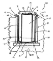
使用済み核燃料を貯蔵するためVVOを使用するとき、使用済み核燃料にて装填されたキャニスタは、VVOの円筒状本体のキャビティ内に配置される。使用済み核燃料は貯蔵のためVVOに配置されたとき、未だ多量の熱を発生させるため、この熱エネルギがVVOキャビティから逃げるための手段を有することが必要である。この熱エネルギは、VVOキャビティを換気することによりキャニスタの外面から除去される。VVOキャビティを換気するとき、冷たい空気が底部の換気ダクトを通ってVVOチャンバに入り、装填したキャニスタを通って上方に流れ且つ、頂部の換気ダクトを通って上昇した温度にてVVOから出る。既存のVVOの底部及び頂部換気ダクトは、図1に示すように、VVOの円筒状本体の実質的に底部及び頂部付近にてそれぞれ周方向に配置されている。 When using VVO to store spent nuclear fuel, a canister loaded with spent nuclear fuel is placed in the cavity of the cylindrical body of the VVO. Since spent nuclear fuel still generates a large amount of heat when placed in the VVO for storage, it is necessary to have a means for this thermal energy to escape from the VVO cavity. This thermal energy is removed from the outer surface of the canister by ventilating the VVO cavity. When ventilating the VVO cavity, cold air enters the VVO chamber through the bottom ventilation duct, flows upward through the loaded canister, and exits the VVO at an elevated temperature through the top ventilation duct. As shown in FIG. 1, the existing VVO bottom and top ventilation ducts are circumferentially arranged substantially near the bottom and top, respectively, of the cylindrical body of the VVO.
熱がキャニスタから逃げることができるようにVVOキャビティを換気することが必要であるが、VVOが十分な放射線遮蔽効果を提供し且つ、使用済み核燃料が外部環境に直接、露呈されないようにすることも必須である。オーバパックの底部付近に配置された入口ダクトは、装填したオーバパックを監視するため、自分自身、短時間、ダクトに接近する位置にいなければならない安全及び監視員に対する特に無防備な放射線の被曝源である。 Although it is necessary to ventilate the VVO cavity so that heat can escape from the canister, the VVO provides sufficient radiation shielding and also prevents spent nuclear fuel from being directly exposed to the external environment. It is essential. An inlet duct located near the bottom of the overpack is a particularly unprotected source of radiation for safety and surveillance personnel who must be in close proximity to the duct for a short time to monitor the loaded overpack. It is.
更に、使用済み核燃料にて装填されたキャニスタが移送キャスクから貯蔵VVOまで移送されるとき、移送キャスクは、キャニスタは、貯蔵VVOキャビティ内に下降するように貯蔵VVOの頂部に積み重ねられる。殆どのキャスクは、極めて大型の構造物であり、重量が250,000lbsもあり、また、高さは4.8768m(16フィート)以上である。移送キャスクを貯蔵VVO/キャスクの頂部に積み重ねるためには、広いスペース、大型の天井クレーン、及び多分、安定化のため拘束システムを必要とするであろう。発電所内にてかかるスペースが利用できないことがしばしばである。最後に、地上貯蔵VVOは、地面上に少なくとも4.8768m(16フィート)立ち、テロリストによる大きな攻撃標的となる。 Further, when a canister loaded with spent nuclear fuel is transferred from the transfer cask to the storage VVO, the transfer cask is stacked on top of the storage VVO such that the canister descends into the storage VVO cavity. Most casks are very large structures, weigh as much as 250,000 lbs, and are over 4.8768 meters (16 feet) in height. Stacking the transfer cask on top of the storage VVO / cask will require a large space, a large overhead crane, and possibly a restraint system for stabilization. Often such space is not available within the power plant. Finally, ground storage VVO stands at least 16 feet above the ground, making it a major attack target by terrorists.
図1には、従来の技術のVVO2が示されている。従来の技術のVVO2は、平坦な底部17と、円筒状本体12と、蓋14とを備えている。蓋14は、ボルト18により円筒状本体12に固定されている。ボルト18は、従来の技術のVVO2が転倒したならば、蓋14が本体12から分離するのを阻止する働きをする。円筒状本体12は、頂部換気ダクト15と、底部換気ダクト16とを有している。頂部換気ダクト15は、円筒状本体12の頂部付近に配置される一方、底部換気ダクト16は、円筒状本体12の底部付近に配置される。底部換気ダクト16及び頂部換気ダクト15の双方が円筒状本体12の円周の周りに配置される。従来の技術のVVO2の全体は、地盤上に配置される。
A
本発明の1つの目的は、移送キャスクが貯蔵VVOの頂部に積み重ねられたとき、積み重ね組立体の高さを低くする、使用済み核燃料のような高レベル廃棄物を貯蔵するシステム及び方法を提供することである。 One object of the present invention is to provide a system and method for storing high level waste, such as spent nuclear fuel, that lowers the height of the stack assembly when transfer casks are stacked on top of a storage VVO. That is.
本発明の別の目的は、必要とする垂直スペースが少なくて済む、使用済み核燃料のような、高レベル廃棄物を貯蔵するシステム及び方法を提供することである。 Another object of the present invention is to provide a system and method for storing high-level waste, such as spent nuclear fuel, that requires less vertical space.
本発明の更に別の目的は、高レベル廃棄物を十分に換気しつつ、貯蔵中、地盤の放射線遮蔽性質を利用する、使用済み核燃料のような、高レベル廃棄物を貯蔵するシステム及び方法を提供することである。 Yet another object of the present invention is to provide a system and method for storing high level waste, such as spent nuclear fuel, that utilizes the radiation shielding properties of the ground during storage while providing sufficient ventilation of the high level waste. Is to provide.
本発明の更なる目的は、十分に保証された原子力発電所内にて得られるものと同一程度又はより高レベルの運転上の防護策を提供する、使用済み核燃料のような、高レベルの廃棄物を貯蔵するシステム及び方法を提供することである。 A further object of the present invention is to provide a high level of waste, such as spent nuclear fuel, that provides the same or higher level of operational protection as obtained within a fully guaranteed nuclear power plant. A system and method for storing food.
本発明の更に別の目的は、地震及びその他の大災害により生じた危険性を減少させ且つ、貯蔵したキャニスタに対する世界貿易センター又はペンタゴン型式の攻撃による潜在的な損傷を実質的に解消する、使用済み核燃料のような、高レベル廃棄物を貯蔵するシステム及び方法を提供することである。 Yet another object of the present invention is to reduce the risk caused by earthquakes and other catastrophes and to substantially eliminate potential damage from World Trade Center or Pentagon type attacks on stored canisters. A system and method for storing high level waste, such as spent nuclear fuel.
本発明の1つの目的は、高レベル廃棄物を移送キャスクから貯蔵VVOまで人間工学的に移送することを許容する、使用済み核燃料のような、高レベル廃棄物を貯蔵するシステム及び方法を提供することである。 One object of the present invention is to provide a system and method for storing high level waste, such as spent nuclear fuel, that permits ergonomic transfer of high level waste from a transfer cask to a storage VVO. That is.
本発明の別の目的は、使用済み核燃料のような、高レベル廃棄物を地盤下に貯蔵するシステム及び方法を提供することである。 Another object of the present invention is to provide a system and method for storing high-level waste, such as spent nuclear fuel, below ground.
本発明の更に別の目的は、環境に放出される放射線の量を減少させる、使用済み核燃料のような高レベル廃棄物を貯蔵するシステム及び方法を提供することである。 Yet another object of the present invention is to provide a system and method for storing high level waste such as spent nuclear fuel that reduces the amount of radiation emitted to the environment.
本発明の更に別の目的は、「急速な浸水(smart flood)」状態を含む、浸水状態の間、貯蔵したキャニスタからの十分な熱除去能力を提供する、使用済み核燃料のような高レベル廃棄物を貯蔵するシステム及び方法を提供することである。 Yet another object of the present invention is to provide a high level waste, such as spent nuclear fuel, that provides sufficient heat removal capability from stored canisters during flood conditions, including “smart flood” conditions. It is to provide a system and method for storing things.
1つの面において、高レベル廃棄物キャニスタを受け入れ且つ貯蔵するキャビティを有し、一部分が地盤下に配置された本体であって、地盤上入口からキャビティの地盤下出口まで伸びる少なくとも1つの入口換気ダクトを有する上記本体とを備える、高レベル廃棄物を貯蔵するシステムである、本発明によって上記及びその他の目的は実現される。地盤上から地盤下の箇所におけるキャビティまで伸びる入口換気ダクトを本体に設けることにより、周囲空気によるキャビティ内のキャニスタの換気を妨害することなく、高レベル廃棄物キャニスタに対し地盤の放射線遮蔽性質を利用することができる。高温の高レベル廃棄物にて装填されたとき、冷たい周囲空気が地盤上の入口に入り、入口換気ダクトを通って移動し、好ましくは、その底部付近にてキャビティに入る。高レベル廃棄物からの熱は冷たい空気を暖め、空気をキャビティ内で上昇させる。加熱された空気はその後、蓋又は本体の地盤上の開口部の何れかに配置された出口換気ダクトを介してキャビティから出る。このように、高レベル廃棄物キャニスタの地盤下の貯蔵は、高レベル廃棄物に対する十分な熱換気を提供しつつ容易となる。 In one aspect, at least one inlet ventilation duct having a cavity for receiving and storing a high-level waste canister, a portion of which is disposed below the ground, extending from the ground entrance to the cavity below ground exit The above and other objects are realized by the present invention, which is a system for storing high-level waste, comprising the main body having: By providing the main body with an inlet ventilation duct that extends from above the ground to the cavity at the location below the ground, the radiation shielding properties of the ground are used against high-level waste canisters without disturbing the ventilation of the canister in the cavity by ambient air can do. When loaded with hot high-level waste, cold ambient air enters the inlet on the ground, travels through the inlet ventilation duct, and preferably enters the cavity near its bottom. The heat from the high level waste warms the cold air and raises the air in the cavity. The heated air then exits the cavity through an outlet ventilation duct located either in the lid or in an opening on the ground of the body. Thus, storage below the ground of the high level waste canister is facilitated while providing sufficient thermal ventilation for the high level waste.
好ましくは、入口換気ダクトの地盤上入口は、本体の側壁にあるものとする。地盤上入口が本体の側壁にあるとき、入口換気ダクトは、細長い実質的にS字形の形状とすることができる。十分な換気を提供するため、本体の両側壁にて本体に2つの入口換気ダクトを設けることが好ましい。入口換気ダクトの地盤上入口を被うため、換気スクリーンが設けられることが好ましい。 Preferably, the above-ground entrance of the inlet ventilation duct is on the side wall of the main body. When the ground inlet is on the side wall of the body, the inlet ventilation duct can be elongated and substantially S-shaped. In order to provide sufficient ventilation, it is preferable to provide the body with two inlet ventilation ducts on both side walls of the body. A ventilation screen is preferably provided to cover the ground entrance of the inlet ventilation duct.
本体は、コンクリートにて出来たものであることが好ましく、キャビティ及び換気ダクトは、コンクリート本体から絶縁して本体がFSAR限界値以上に加熱されるのを防止すること、及び入口換気ダクトに入る空気がキャビティに入る前に加熱されるのを防止することの双方を行うことができる。入口換気ダクト及びキャビティは、地盤下液体が侵入しないように密閉的に密封された一体型部分となるような構造とされることが好ましい。このことは、キャビティ内部が腐食する可能性を減少させることになる。この実施の形態において、キャビティを裏当てするためスチール殻体を設け、入口換気ダクトはスチールライニングで出来たものとすることができる。次に、殻体及び入口換気ダクトを互いに溶接して密閉的シールを実現することができる。また、殻体及び入口換気ダクトと一体型である底部板をキャビティの下方に設けることもできる。該システムはまた、強化コンクリートスラブのような、その上に本体が配置される基部を備えることもできる。 The body is preferably made of concrete, and the cavity and ventilation duct are insulated from the concrete body to prevent the body from being heated above the FSAR limit, and the air entering the inlet ventilation duct Both can be prevented from being heated before entering the cavity. The inlet ventilation duct and cavity are preferably structured to be an integral part that is hermetically sealed to prevent penetration of subsurface liquid. This will reduce the possibility of corrosion inside the cavity. In this embodiment, a steel shell may be provided to back the cavity and the inlet ventilation duct may be made of steel lining. The shell and inlet ventilation duct can then be welded together to achieve a hermetic seal. Also, a bottom plate that is integral with the shell and the inlet ventilation duct can be provided below the cavity. The system can also include a base on which the body is disposed, such as a reinforced concrete slab.
システムはまた、キャビティの底部/床に配置された支持ブロックを有することもできる。好ましくは、これらの支持ブロックは周方向に隔てられ且つ、キャニスタが貯蔵のためキャニスタ内に配置されたとき、高レベル廃棄物のキャニスタとキャビティの底面との間に入口空気プレナムを提供するようにする。入口空気プレナムが存在することは、キャビティの好適な換気を容易にするのを助ける。支持ブロックは、低炭素鋼にて出来たものとすることができる。以下に説明するように、本発明の幾つかの面において、支持ブロックとキャビティ内への入口換気ダクトの地盤下の出口(すなわち開口部)との間の相対的な高さは、浸水状態の間、過熱に対して保護することになろう。 The system can also have a support block located at the bottom / floor of the cavity. Preferably, the support blocks are circumferentially spaced and provide an inlet air plenum between the high level waste canister and the bottom surface of the cavity when the canister is disposed in the canister for storage. To do. The presence of the inlet air plenum helps facilitate proper ventilation of the cavity. The support block can be made of low carbon steel. As will be described below, in some aspects of the invention, the relative height between the support block and the sub-floor outlet (ie, the opening) of the inlet ventilation duct into the cavity is a submerged condition. During this time, it will protect against overheating.
高レベル廃棄物を貯蔵する間、システムは、本体の頂部に配置され且つ、キャビティを被う蓋を更に備えることが好ましい。好ましくは、高レベル廃棄物キャニスタがキャビティ内に配置され、蓋が本体の頂部に配置されてキャビティを取り囲むとき、キャニスタと蓋との間に出口空気プレナムが存在するようにする。該蓋は、該蓋が本体の頂部に配置されたとき、キャビティ内に突き出すせん断リングを備えることも好ましい。せん断リングは、地震、衝撃性ミサイル又はその他の反射体からの側方力に対して極めて大きいせん断抵抗を提供し、これにより、システムの放射線遮蔽の完全さを維持する。 During storage of high level waste, the system preferably further comprises a lid disposed on the top of the body and covering the cavity. Preferably, an exit air plenum is present between the canister and the lid when the high level waste canister is disposed within the cavity and the lid is disposed at the top of the body and surrounds the cavity. The lid also preferably includes a shear ring that projects into the cavity when the lid is placed on top of the body. The shear ring provides a very high shear resistance to lateral forces from earthquakes, impact missiles or other reflectors, thereby maintaining the integrity of the system's radiation shielding.
蓋は、加熱された空気がキャビティから出るのを許容する少なくとも1つの出口換気ダクトを備えることも好ましい。この出口換気ダクトは、例えば、蓋の側壁における水平方向通路とすることができる。この実施の形態において、蓋の出口換気ダクトは、本体の入口換気ダクトの地盤上入口から周方向に且つ方位角にて分離されている。このことは、蓋を介してキャビティから出る加熱された空気が本体の入口換気ダクト内に吸引され且つ、キャビティ内に戻るのを阻止するのを助けることになる。その他の実施の形態において、出口換気ダクトをVVO自体の本体内に配置することができる。 The lid also preferably comprises at least one outlet ventilation duct that allows heated air to exit the cavity. This outlet ventilation duct can be, for example, a horizontal passage in the side wall of the lid. In this embodiment, the lid outlet ventilation duct is separated circumferentially and azimuthally from the ground inlet of the main body inlet ventilation duct. This will help to prevent heated air exiting the cavity through the lid from being drawn into the body inlet ventilation duct and back into the cavity. In other embodiments, the outlet ventilation duct can be located within the body of the VVO itself.
本体の過半部分は地盤下に配置されることが好ましく、本体は地盤上を約106.68cm(42インチ)以下だけ、伸びることがより好ましい。また、キャビティの高さの過半部分は地盤下にあり、高レベル廃棄物キャニスタがキャビティ内に下降されたとき、キャニスタの少なくとも過半部分が地盤下となるようにすることが好ましい。最も好ましくは、キャニスタの全体が、貯蔵する間、地盤下になるようにする。 The majority of the body is preferably located below the ground, and more preferably the body extends by about 106.68 cm (42 inches) or less above the ground. It is also preferred that the majority of the cavity height is below the ground and that at least the majority of the canister is below the ground when the high level waste canister is lowered into the cavity. Most preferably, the entire canister is underground during storage.
別の面において、本発明は、上述したシステムであって、少なくとも1つの出口換気ダクトを有するシステムを提供するステップと、キャニスタの過半部分が地盤下となるように高レベル廃棄物をキャビティ内に下降させるステップと、キャビティを取り囲むように蓋を本体の頂部に配置するステップとを備え、キャニスタの換気が本体の入口換気ダクトを通ってキャビティに入る冷たい空気により提供され、冷たい温空気は高レベル廃棄物によりキャビティ内で加熱され、暖かい空気は出口換気ダクトを通ってキャビティから出るようにした、高レベル廃棄物を貯蔵する方法である。本発明の方法を実施するために使用されるシステムは、上述した設計仕様の任意のものを含むことができる。 In another aspect, the present invention provides a system as described above, comprising a system having at least one outlet ventilation duct, and placing high level waste in the cavity such that a majority of the canister is below ground. Lowering and placing a lid on the top of the body so as to surround the cavity, canister ventilation is provided by the cold air entering the cavity through the inlet ventilation duct of the body, and the cold hot air is at a high level A method of storing high-level waste that is heated in the cavity by the waste so that warm air exits the cavity through the outlet ventilation duct. The system used to implement the method of the present invention can include any of the design specifications described above.
更に別の面において、本発明は、高レベル廃棄物キャニスタを受け入れ且つ貯蔵し、頂部と、底部と、底面とを有するキャビティを備える本体と、周囲空気入口からキャビティの底部付近の出口までの通路を形成する少なくとも1つの入口換気ダクトと、キャビティの頂部付近から周囲空気までの通路を形成する少なくとも1つの出口換気ダクトと、高レベル廃棄物キャニスタの底部とキャビティの底面との間に空気プレナムが形成されるように高レベル廃棄物キャニスタをキャビティ内に支持する手段とを備え、支持手段が、キャニスタの底部が出口の頂部よりも下方となるように高レベル廃棄物キャニスタをキャビティ内に支持するようにした、高レベル廃棄物を貯蔵するシステムである。好ましくは、支持手段は、キャニスタの底部が出口の頂部よりも少なくとも5.08cm(2インチ)だけ下方となるように高レベル廃棄物キャニスタをキャビティ内に支持するものとする。 In yet another aspect, the present invention receives and stores a high level waste canister, a body comprising a cavity having a top, a bottom, and a bottom, and a passageway from an ambient air inlet to an outlet near the bottom of the cavity. An air plenum between the bottom of the high-level waste canister and the bottom of the cavity, at least one inlet ventilation duct that forms a channel, at least one outlet ventilation duct that forms a passageway from near the top of the cavity to ambient air Means for supporting the high level waste canister in the cavity as formed, wherein the support means supports the high level waste canister in the cavity such that the bottom of the canister is below the top of the outlet. This is a system for storing high-level waste. Preferably, the support means shall support the high level waste canister in the cavity such that the bottom of the canister is at least 2 inches below the top of the outlet.
本発明のこの面において、VVOの本体は、完全に又は部分的に地盤上となるものとすることができる。本体の少なくとも一部分が地盤下に配置される1つの実施の形態において、入口換気ダクトの周囲空気入口は地盤上となる一方、入口換気ダクトの出口は地盤下となる。 In this aspect of the invention, the VVO body may be completely or partially on the ground. In one embodiment where at least a portion of the body is located below the ground, the ambient air inlet of the inlet ventilation duct is above the ground, while the outlet of the inlet ventilation duct is below the ground.
本体の全体が地盤上となる本発明のこの面の1つの実施の形態において、入口換気ダクトの周囲空気入口及び出口の双方が地盤上となるようにすることができる。この実施の形態において、入口換気ダクトは、周囲空気入口から支持手段により支持されたキャニスタまでの視線が存在しないような形状とされよう。例えば、入口換気ダクトは、L字形、角度付き形状、S字形又は湾曲形状の一部分を備えることができる。このことは、キャニスタにより放出された放射線が周囲環境に「照射する」のを防止するために行われる。 In one embodiment of this aspect of the invention in which the entire body is on the ground, both the ambient air inlet and outlet of the inlet ventilation duct can be on the ground. In this embodiment, the inlet ventilation duct will be shaped such that there is no line of sight from the ambient air inlet to the canister supported by the support means. For example, the inlet ventilation duct can comprise a portion of an L shape, an angled shape, an S shape, or a curved shape. This is done to prevent the radiation emitted by the canister from “irradiating” the surrounding environment.
更に別の面において、本発明は、高レベル廃棄物キャニスタを受け入れるキャビティを形成する殻体であって、その少なくとも一部分が地盤下に配置された上記殻体と、地盤上入口からキャビティの底部付近の地盤下出口まで伸びる少なくとも1つの入口換気ダクトであって、地盤下流体が侵入しないようキャビティが密閉的に密封されるように殻体に接続された上記少なくとも1つの入口換気ダクトとを備える、高レベル廃棄物を貯蔵するシステムである。 In yet another aspect, the present invention provides a shell forming a cavity for receiving a high-level waste canister, the shell having at least a portion thereof disposed below the ground, and the bottom of the cavity from the top entrance to the ground. At least one inlet ventilation duct extending to a subsurface outlet of the at least one inlet, wherein the at least one inlet ventilation duct is connected to the shell so that the cavity is hermetically sealed to prevent ingress of subsurface fluid. A system for storing high-level waste.
更に別の面において、本発明は、地盤下穴を提供するステップと、高レベル廃棄物のキャニスタを受け入れるキャビティを成形する殻体であって、その少なくとも一部分が地盤下に配置された上記殻体と、入口からキャビティの底部付近の出口まで伸びる少なくとも1つの入口換気ダクトであって、殻体に接続された上記入口ダクトとを備えるシステムを提供するステップと、入口換気ダクトの入口が地盤上となり、キャビティ内への入力換気ダクトの出口が地盤下となるように装置を穴内に配置するステップと、穴を工学的に設計した充填材にて充填するステップと、高レベル廃棄物キャニスタをキャビティ内に下降させるステップとを備える、高レベル廃棄物を貯蔵する方法である。 In yet another aspect, the present invention provides a shell for forming a ground hole and forming a cavity for receiving a high-level waste canister, wherein at least a portion of the shell is disposed below the ground. Providing a system comprising: an inlet ventilation duct extending from the inlet to an outlet near the bottom of the cavity, the inlet duct connected to the shell; and the inlet of the inlet ventilation duct is above ground Placing the device in the hole so that the outlet of the input ventilation duct into the cavity is below the ground, filling the hole with engineered filler, and placing the high-level waste canister in the cavity And storing the high-level waste.
別の面において、本発明は、高レベル廃棄物のキャニスタを受け入れるキャビティを形成する殻体であって、その少なくとも一部分が地盤下に配置された上記殻体と、キャビティの頂部付近から周囲雰囲気まで伸びる通路を形成する少なくとも1つの換気ダクトと、を備え、地盤下の流体が侵入しないようにキャビティが密閉的に密封される、高レベル廃棄物を貯蔵するシステムである。 In another aspect, the present invention provides a shell that forms a cavity for receiving a high-level waste canister, the shell having at least a portion thereof disposed below the ground, and from near the top of the cavity to the ambient atmosphere. A system for storing high-level waste, comprising at least one ventilation duct forming an extending passageway, wherein the cavity is hermetically sealed to prevent intrusion of subsurface fluid.
更なる面において、本発明は、高レベル廃棄物のキャニスタを受け入れるキャビティを形成する殻体であって、その少なくとも一部分が地盤下に配置された上記殻体と、キャビティの頂部付近から周囲雰囲気まで伸びる通路を形成する少なくとも1つの換気ダクトとを備えるシステムを提供するステップを備え、地盤下の流体が侵入しないようにキャビティが密閉的に密封され、キャニスタの少なくとも過半部分が地盤下となる迄、低熱の高レベル廃棄物のキャニスタをキャビティ内に下降させるステップを備える、低熱の高レベル廃棄物を貯蔵する方法である。 In a further aspect, the present invention provides a shell forming a cavity for receiving a high-level waste canister, the shell having at least a portion thereof disposed below the ground, and from near the top of the cavity to the ambient atmosphere. Providing a system comprising at least one ventilation duct that forms an extending passageway, until the cavity is hermetically sealed to prevent intrusion of fluid below the ground, and at least a majority of the canister is below the ground, A method for storing low heat, high level waste, comprising lowering a low heat, high level waste canister into a cavity.
本発明は特定型式の高レベル廃棄物に何ら限定されるものではないとの理解の下、使用済み燃料を貯蔵するシステム及び方法に関し本発明を以下に説明する。 With the understanding that the present invention is not limited to any particular type of high level waste, the present invention is described below with respect to a system and method for storing spent fuel.
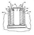
図2及び図3を参照すると、本発明の第一の実施の形態に従った地下VVO20が示されている。地下VVO20は、使用済みキャニスタの移送作業のため100トン及び125トン移送キャスクと完全に適合可能な垂直の換気、乾燥した使用済み燃料貯蔵システムである。地下VVO20は、任意の寸法又は型式の移送キャスクと適合し得るよう形態変更し且つ設計することができる。地下VVO20は、地上オーバパック(図1の従来技術のVVO2のような)に代えて独立的な使用済み燃料貯蔵設備(「ISFSI」)にて貯蔵すべく使用済み燃料キャニスタを受け入れる設計とされている。自立し且つ定着されたオーバパックモデルにて貯蔵し得るよう工学的に設計された全ての型式の使用済み燃料キャニスタを、地下VVO20内に貯蔵することができる。
2 and 3, an
本明細書にて使用するように、「キャニスタ」という語は、広く、非限定的に、多目的キャニスタ及び熱伝達性キャスクを含む、任意の使用済み燃料封じ込め装置を含む。例えば、世界の幾つかの地域において、使用済み燃料は移送されて且つ、金属キャスク内に直接、組み込まれたハニカム格子工作物/バスケットを有する金属キャスク内に貯蔵される。かかるキャスク及び同様の封じ込め装置は、本明細書にて使用するキャニスタという語の点にてキャニスタとしての資格を有し、また、以下に説明するように、地下VVO20と共に使用することができる。
As used herein, the term “canister” broadly includes any spent fuel containment device, including but not limited to a multi-purpose canister and a heat transfer cask. For example, in some parts of the world, spent fuel is transported and stored in metal casks with honeycomb grid workpieces / baskets incorporated directly into the metal casks. Such casks and similar containment devices are qualified as canisters in terms of canisters as used herein and can be used with
地下VVO20は、本体21と、基部22と、取り外し可能な蓋41とを備えている。本体21は、コンクリートにて出来ているが、その他の適宜な材料にて出来たものとしてもよい。本体21は、矩形の形状であるが、例えば、円筒状、円錐形、球形、半球形、三角形又は不規則の形状のような、任意の形状のものとすることができる。本体21の一部分は、地盤下に配置され、このため、頂部分24のみが地盤上位置23から突き出す。好ましくは、本体21の高さの少なくとも大部分が地盤下に配置されるものとする。本体21の頂部分21が地面の水準23よりも上方に伸びる正確な高さは、大幅に変更することができ、キャニスタの寸法、貯蔵すべき使用済み燃料の放射能レベル、ISFSIのスペースの制限、ミサイル型及び地上攻撃のされ易さを考慮した地理的位置、自然災害(地震、洪水、竜巻、ハリケーン、津波等のような)の頻度及び受け易さを考慮した地理的位置、環境状態(温度、析出レベルのような)及び(又は)地下水位のような、多数の設計上の条件に依存する。好ましくは、本体21の頂部分24は、地面の水準23から約1066.8mm(約42インチ)以下の位置にあり、地面の水準23から約152.4mm(約6インチ)ないし914.4mm(36インチ)上方にあることが最も好ましい。
The
幾つかの実施の形態において、本体21の全高さは地盤下(図8D及び図8Eに図示)となるようにすることも好ましい。以下により詳細に説明するように、本体の全高さが地盤下にあるとき、本体の最上面のみが地盤上の周囲雰囲気に露呈されよう。
In some embodiments, it is also preferable that the total height of the
図2及び図3を更に参照すると、本体21は、円筒状キャビティ26を形成する(図3に最も良く図示)。キャビティ26は、円筒状の形状であるが、キャビティ26は、何らかの特定の寸法、形状、及び(又は)深さに限定されるものではなく、本発明の精神から逸脱せずに、ほぼあらゆる形状のキャニスタを受け入れ且つ貯蔵し得る設計とすることができる。本発明を実施するのに必ずしも必要ではないが、キャビティ26の水平方向断面寸法及び形状は該特定の地下VVOと共に使用すべきキャニスタ型式の水平方向断面寸法及び形状に全体として相応する設計とすることが好ましい。より具体的には、キャビティ26の寸法及び形状は、使用済み燃料キャニスタ(キャニスタ70のような)が貯蔵のためキャビティ26内に配置されたとき、キャニスタの外側壁とキャビティ26の側壁との間に小さい隙間が存在するような設計とされることが望ましい。
With further reference to FIGS. 2 and 3, the
貯蔵したキャニスタの側壁とキャビティ26の側壁との間に小さい隙間が形成されるように、キャビティ26を設計することは、大災害のとき、キャニスタがキャビティ内にて動くことができる程度を制限し、これによりキャニスタ及びキャビティの壁に対する損傷を最小にし且つ、キャニスタがキャビティ内にて転倒するのを防止することとなる。この小さい隙間は、また、使用済み核燃料が冷却する間、加熱された空気が流れるのも容易にする。隙間の正確な寸法は、任意の所定の状況に対し所望の流体流れ動力学及び熱伝達能力を実現し得るよう制御し/設計することができる。例えば、幾つかの実施の形態において、隙間は25.4mm(1インチ)ないし76.2mm(3インチ)とすることができる。小さい隙間は放射線の流れを減少させる。
Designing the
キャビティ26の底部に対して入口換気を提供し得るよう本体21に2つの入口換気ダクト26が設けられる。入口換気ダクト25は、地盤入口27から地盤下出口28まで伸びる細長い実質的にS字形の通路である。地盤上入口27は、本体21の頂部分24の両側壁に配置され且つ、地面の水準23の上方の周囲空気に対し開放している。本明細書にて使用するように、周囲空気、周囲雰囲気又は外部雰囲気という語は、地下VVOの外部の環境/空気を意味し、自然の外部環境及び建物、テント、洞窟、トンネル又はその他の人工又は自然の囲い物内の空間を包含するものである。
Two
地盤下出口28は、地面の水準23の下方の位置にてその底部付近でキャビティ26内に開放している。このように、入口換気ダクト25は、キャビティ26の底部が十分に地盤下にあるにも拘らず、周囲空気がキャビティ26の底部に入るための通路を提供する。物及びその他の塵が入口換気ダクト25の通路に入り且つ、該通路を閉塞し得ないよう換気スクリーン31(図3)が地盤上入口27を被うように設けられる。入口換気ダクト25が細長いS字形の形状をしている結果、地盤上入口27は、自立する地上VVOsにて一般的である増大した被曝量の位置でなくなる。地盤下出口28は、キャビティ26の壁の底部付近にて開放しているとして示されているが、地盤下出口28は、望まれるようにキャビティ26の床に配置することができる。このことは、入口換気ダクト25の形状を適宜に再設定し且つ、底部板38を通ってキャビティ26内に達する開口部を形成することにより実現することができる。かかる実施の形態において、基部22は、入口換気ダクト25が伸びるときに通る本体21の一部であると見なすことができる。
The
地盤上ダクト27は、地面の水準23から約254mm(約10インチ)の上方の高さにて本体21の側壁に配置されている。しかし、地盤上入口27の高さは、本発明を制限するものではない。入口27は、図8D及び図8Eに示すように、水平/面一を含んで、地面の水準よりも上方の任意の所望の高さに配置することができる。地盤上入口27を実質的に、地面の水準23よりも上方に上昇させることは、雨又は浸水がキャビティ26内に入る可能性を減少させるのに役立つ。浸水地域におけるIFSI’sの場合、浸水は地面の水準よりも多分、304.8mm(1フィート)以上上昇し、このため、入口換気ダクト25を介してキャビティ26に入る可能性があることが分かる。しかし、図6に関して以下に説明するように、地下VVO20は、最悪の浸水状態を安全で且つ、効果的な仕方にて取り扱うよう特に設計されている。
The
地盤上入口27は、本体21の側壁に配置されることが好ましいが、地盤上入口は、かかる位置にのみ限定されず、所望であるならば、例えば、本体の最上面(又は、任意のその他の表面)を含む、本体の任意の箇所に配置することができる。本体21における地盤上入口27に対する可能な位置の更なる例は、図8Aないし図8Eに示されている。
The
再度、図2及び図3を参照すると、入口換気ダクト25は、約152.4mm(約6インチ)×1016mm(40インチ)の矩形の断面積を有している。しかし、例えば、丸形、楕円形、三角形、六角形、八角形等のような、任意の断面形状及び(又は)寸法のものを使用することができる。更に、入口換気ダクト25の形状は、細長い基本的にS字形の通路であるが、地盤上入口27にて許容可能な被曝量を依然として実現する多数の形状を使用することができる。例えば、細長いS字形の形状ではなくて、入口換気ダクトは、地盤上入口から地盤下出口までジグザグの形状、傾斜した直線状の形状、全体としてL字形の形状、又は任意の角度、直線状又は湾曲した形状の組み合わせにて伸びるものとすることができる。入口換気ダクトの正確な形状、寸法及び断面の形態は、設計上の好みの問題であり、VVOの本体の厚さ、キャビティ内に貯蔵された使用済み燃料の放射能レベル、使用済み燃料キャニスタの温度、ダクトを通る所望の流体の流れ動力学及び本体における地盤上入口の配置(すなわち、地盤上入口換気口/開口部が本体の側壁、その最上面又は本体の幾つかのその他の表面に配置されるかどうか)というような因子によって決まる。入口換気ダクト25に対して可能な形状の更なる例は、図8Aないし図8Eに示されている。
Referring again to FIGS. 2 and 3, the
入口換気ダクト25は、低炭素鋼ライナーにより形成されることが好ましい。しかし、入口換気ダクト25は、任意の材料にて出来たものとしてよく、又は、単にライニング無しにてコンクリート本体21内に形成された通路としてもよい。
The
図3に最も良く示すように、キャビティ26は、厚いスチール殻体34及び底部板38により形成される。殻体34、底部板38及び入口換気ダクト25は、低炭素鋼のような、金属で出来ていることが好ましいが、ステンレス鋼、アルミニウム、アルミニウム合金、プラスチック等のようなその他の材料で出来たものでもよい。入口換気ダクト25は、殻体34及び底部板38にシール接続され、一体型/単一物構造体100(図9に独立的に図示)を形成し、該構造体100は、地盤下水及びその他の流体が侵入しないよう密閉的に密封されている。溶接可能な金属の場合、このシール接続は、溶接又はガスケットを使用することを備えることができる。このように、水又はその他の流体がキャビティ26に入る唯一の経路は、地盤上入口27又は蓋41の出口換気ダクト42を通るものである。図9ないし図15に関して以下に説明するように、一体型構造体自体が1つの発明であり、本体21を使用せずに、使用済み核燃料を貯蔵するため使用することができる。
As best shown in FIG. 3, the
コールタールエポキシ等のような、適当な防腐剤を殻体34、底部板38及び入口換気ダクト25の露出面に施し、密封効果を保証し、材料の劣化を少なくし且つ、火災から保護し得るようにする。適宜なコールタールエポキシは、ミズリー州、セントルイスのカーボラインカンパニー(Carboline Company)からビティマスティック(Bitumastic)300Mという商標名にて製造されているものである。本発明の地下VVOの幾つかの実施の形態において、底部板は使用されないであろう。
Appropriate preservatives, such as coal tar epoxy, can be applied to the exposed surfaces of the
コンクリート本体21は、殻体34及び入口換気ダクト25を取り囲む。本体21は、殻体34及び入口換気ダクト25に対する非構造的保護を提供する。殻体34とコンクリート本体21との間の境界部及び入口換気ダクト25とコンクリート本体21との間の境界部に絶縁体37が提供される。使用済み燃料キャニスタ70からコンクリート本体21への崩壊熱の過剰な伝達を防止するため、絶縁体37が設けられており、これによりコンクリートの全体温度をFSAR限界値以内に維持することができる。また、殻体34及び入口換気ダクト25をコンクリート本体21から絶縁することは、入って来る冷たい空気がキャビティ26に入る前に、その冷たい空気が加熱されるのを最小限にする働きもする。絶縁体の適宜な形態は、非限定的に、アルミナ−シリカ耐火粘土のブランケット(カオウールブランケット)、アルミナ及びシリカの酸化物(カオウールSブランケット)、アルミナ−シリカ−ジルコニア繊維(セラブランケット)及びアルミナ−シリカ−クロミア(セラクロムブランケット)を含む。
The
入口換気ダクト25をキャビティ26内の使用済み燃料の熱負荷から絶縁することは、使用済み燃料の十分な換気/冷却効果を容易にし且つ、維持する上で極めて重要である。絶縁過程は、多岐に亙る方法にて実施することができ、その何れも本発明を限定するものではない。例えば、殻体34及び入口換気ダクト25の外側に絶縁性材料を追加することに加えて、キャビティ26と入口換気ダクト25との間にてコンクリート本体21内に空隙を提供することにより、入口換気ダクト25を絶縁することも可能である。この空隙は、所望であれば、不活性気体又は空気にて充填することができる。更に、絶縁効果を提供するために使用される手段に関係なく、絶縁手段は、殻体34又は入口換気ダクト25の外面上に配置することのみに限定されるものではなく、キャビティ26と入口換気ダクト25との間の任意の位置に配置することができる。
Insulating the
本体21は、底部板38、殻体34及び換気ダクト25により形成された一体型のスチールユニットと共に、基部22の頂部に配置される。基部22は、非限定的に、ACI−349のような、認定された業界標準の荷重の組み合わせを満足させる設計とされた強化コンクリートスラブである。基部22は、矩形の形状であるが、円形、楕円形、三角形、六角形、八角形、不規則な形状等のような、本体21を支持するため必要な任意の形状とすることができる。十分な荷重支持条件を実現するため基部を使用することが好ましいが、かかる基部を使用することが不要な状況が生じる可能性がある。
The
図2を再度参照すると、地下VVO20は、取り外し可能な換気した蓋41を有している。蓋41は本体21の頂部に配置され、これによりキャビティ26を実質的に取り囲み、キャニスタ70がキャビティ26内に配置されたとき、放射線がキャビティ26の頂部から逃げないようにする。蓋41が本体21の頂部に配置され、使用済み燃料キャニスタ70がキャビティ26内に配置されたとき、キャニスタ70の最上面と蓋41との間に出口空気プレナム36が形成される。出口空気プレナム36は、高さが最小76.2mm(3インチ)であることが好ましいが、任意の所望の高さとすることができる。正確な高さは所望の流体流れ動力学、キャニスタの高さ、VVOの高さ、キャビティの深さ、キャニスタの熱負荷等のような設計条件によって決まろう。
Referring back to FIG. 2, the
蓋41は、4つの出口換気ダクト42を有している。出口換気ダクト42は、キャビティ26の頂部(特に、出口空気プレナム36)から周囲空気への通路を形成し、加熱された空気はキャビティ26から逃げることができる。出口換気ダクト42は、蓋41の側壁30を貫通して伸びる水平方向通路である。しかし、出口換気ダクトは、垂直、L字形、S字形、角度付き、湾曲等のような任意の形状又は向きのものとすることができる。出口換気ダクト42は蓋41自体に配置されるから、本体21の全体高さは最小となる。
The lid 41 has four
蓋41は、コンクリートで出来た屋根35を備えている。屋根35は、放射線遮蔽効果を提供し、このため放射線がキャビティ26の頂部から逃げることはない。蓋41の側壁30は環状リングである。出口空気プレナム36は、加熱された空気を出口管ダクト42を介して除去することを容易にするのを助ける。出口換気ダクト42から出る加熱された空気が換気ダクト25内に吸い上げられて戻るのを最小にするため、出口換気ダクト42は、入口換気ダクト25から方位角にて且つ周方向に分離されている。
The lid 41 includes a
換気した蓋41は、せん断リング47も備えている。蓋41が本体21の頂部に配置されたとき、せん断リング47は、キャビティ26内に突き出し、これにより、地震、衝撃性ミサイル又はその他の発射体による側方力に対する極めて大きいせん断抵抗を提供する。蓋41は、貫通して伸びるボルト(図示せず)により本体21に固定される。
The ventilated lid 41 is also provided with a shear ring 47. When the lid 41 is placed on top of the
図示しないが、形状及び(又は)寸法に関係なく、ダクトの光子減衰器を地下VVO20の入口換気ダクト25及び(又は)出口換気ダクト42の全てに挿入することが好ましい。適宜なダクトの光子減衰器は、その教示内容を参考として引用し、本明細書に含めたボングラジオ(Bongrazio)の米国特許第6,519,307号に記載されている。
Although not shown, it is preferable to insert the photon attenuator of the duct into all of the
次に、図4を参照すると、地下VVO20にて使用することのできる蓋50の1つの実施の形態が示されている。蓋50は、蓋41と同様の設計上の特徴を保持しており、上述した蓋の設計の特徴をより完全に開示し得るように図示されている。蓋50は、側壁52に4つの水平方向出口換気ダクト51を有している。せん断リング54がキャビティ26内に嵌まるよう蓋50の底部に設けられている。蓋50を本体21の頂部のタップ穴に固定するためボルト18が使用される。
Referring now to FIG. 4, one embodiment of a
出口換気ダクトは地下VVO20の蓋50内に配置された状態で示されているが、本発明は、このように限定されるものではない。例えば、出口換気ダクトは、地盤上の位置にて地下VVOの本体内に配置することができる。この着想は、図8Aないし図8Eに示されている。出口換気ダクトが地下VVOの本体内に配置されるならば、周囲空気に対する出口換気ダクトの開口部は、本体の側壁、その最上面又は任意のその他の面に配置することができる。出口換気ダクトが蓋内に配置される場合と同様に、出口換気ダクトは、地下VVO自体の本体内に配置されたとき、多岐に亙る形状及び(又は)形態をとることができる。入口換気ダクトの場合と同様に、出口換気ダクトは、低炭素鋼ライナーにて形成されることが好ましいが、任意の材料にて出来たものとし又は単にライニング無しにてコンクリート本体21又は蓋41内に形成された通路としてもよい。入口及び出口換気ダクトの双方を有する本発明の全ての実施の形態において、出口換気ダクトの開口部は、入口及び出口空気流れの間の相互作用を最小にし得るよう入口換気ダクトの入口から方位角にて且つ周方向に分離されることが好ましい。地下VVO20と共に使用される蓋の形状及び型式に関し何ら制限はない。
Although the outlet ventilation duct is shown as being disposed within the
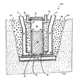
図2を再度参照すると、土29は本体21をその高さのほぼ全体に亙って取り囲む。使用済み燃料キャニスタ70がキャビティ26内に配置されたとき、キャニスタ70の全体ではないにしても、その少なくとも過半部分は地盤下となる。好ましくは、キャニスタ70の全高さは地盤下となり、土29の遮蔽効果を完全に活用し得るようにする。このように、土29は、地下VVO20内に貯蔵された使用済み燃料に対し、地上オーバパックにて実現することのできない程度の放射線遮蔽効果を提供する。地下VVO20は、外観上、障害物無しであり、また、地下VVO20が転倒する危険はない。更に、地下VVO20は、自由場の加速を拡大し且つ、地上の自立オーバパックの安定性を危険にする可能性のある、土−構造体の相互作用効果と取り組む必要はない。
Referring again to FIG. 2, the
図6を参照すると、図2の領域VI−VIが詳細に示されている。図6には、地下VVO20が好ましくない衝撃を伴わず浸水状態に成功裏に耐えることのできることを保証するために重要である設計上の特徴が示してある。キャニスタ70をその上に配置することのできるようにキャビティ26の底面(板38により形成される)に支持ブロック32が設けられる。支持ブロック32は、互いから周方向に隔てられている(図7に図示)。キャニスタ70が貯蔵のためキャビティ26内に装填されたとき、キャニスタ70の底面71は支持ブロック32上に静止し、キャニスタ70の底面71とキャビティ26の底面/床との間に入口空気プレナム33を形成する。支持ブロック32は、低炭素鋼にて出来ており且つ、キャビティ26の底面に溶接されることが好ましい。その他の適宜な構造材料は、非限定的に、強化コンクリート、ステンレス鋼及びその他の金属合金を含む。
Referring to FIG. 6, the area VI-VI of FIG. 2 is shown in detail. FIG. 6 shows design features that are important to ensure that the
支持ブロック32は、エネルギ/衝撃吸収機能も果たす。支持ブロック32は、米国、カリフォルニア州のヘクセル(Hexcel)コーポレーションが製造するもののようなハニカム格子型式のものであることが好ましい。
The
支持ブロック32は、キャニスタ70の底面71が入口換気ダクト25の地盤下出口28(図2)の頂部74よりも低くなるように特に設計されている。好ましくは、支持ブロック32は、キャニスタ70の底面71が地盤下出口28の頂部74から約50.8mm(約2インチ)ないし152.4mm(6インチ)だけ下方となるような設計とされるものとする。しかし、適宜な設計を通じて任意の所望の高さの差を実現することができる。その底面71が地盤下出口28の頂部74よりも低くなるようにキャニスタ70をキャビティ26内で支持することにより、地下VVO20は、口語的に「急速な浸水」と称される最悪の浸水状態の下でさえ、キャニスタ70に対し十分な冷却効果を提供する。「急速な浸水」は、水位が入口換気ダクト25を通る空気流を完全に遮断するのに丁度十分であるようにVVOに溢れるものである。換言すれば、水位は、地盤下出口28の頂部74と丁度、等しい。
The
しかし、キャニスタ70の底面71が地盤下出口28の頂部74よりも低い高さに配置されているから、地下VVO20は、「急速な浸水」状態を十分に取り扱うことができる。従って、「急速な浸水」が生じたならば、キャニスタ70の底部は水と接触する(すなわち水に浸かる)ことになろう。水の熱除去効果は空気の100倍以上であるから、熱を効率的に除去し且つキャニスタ70を低温状態に保つためには、底部が湿っていればよい。キャニスタ70が水中に浸かる程度が深ければ深い程、キャニスタ70及びその保持された燃料はより冷たいままであることになろう。キャビティ26内の水がキャニスタ70の底部により加熱されるに伴い、水は蒸発し、環状空間60を介してキャビティ26を通って上昇し且つ、出口換気ダクトを介してキャビティ26から出る。したがって、キャニスタの冷却作用は、換気冷却より蒸発水による冷却に変わる。
However, since the
1つの実施の形態において、入口換気ダクト25の地盤下出口28は、高さ203.2mm(8インチ)×幅1016mm(40インチ)であり、また、入口空気プレナム33の高さは152.4mm(6インチ)である。このことは、50.8mm(2インチ)の高さの差を提供することになる。
In one embodiment, the
図6に詳細に示した地下VVO20の高さの差の設計の特徴は、地下VVO20のその他の特徴と独立的に、「急速な浸水」を取り扱うべく自立する地面上キャスク及びVVOs内に組み込むことができることを理解すべきである。このように、この着想は、本出願の独立的な発明の特徴である。地上VVOs内に組み込まれたとき、入口換気ダクトは、放射線が入口換気ダクトから周囲環境に逃げることができないような設計とする必要がある。このことは、キャニスタが貯蔵キャビティ内への入口ダクトの開口部の下方にあるため、危険である。この実施の形態において、入口換気ダクトは、周囲空気から貯蔵キャビティ内のキャニスタに対する視線が存在しないような形状とする。例えば、入口換気ダクトは、L字形、角度付き、S字形又は湾曲した形状の一部分を備えることができる。
The height difference design features of the
更に、図6の高さの差の設計の特徴は支持ブロック32を使用して実現されるが、支持ブロック32無しにて本発明のこの特徴を具体化することも可能である。かかる実施の形態において、キャニスタ70は、キャビティ26内に配置され且つ、キャビティ26の床に直接、静止することになる。しかし、空気入口プレナム33を形成するから、また、支持ブロック32を使用することは塵埃がキャビティ26の底部にて取り込まれるのを阻止するのに役立つことから、支持ブロック32を使用することは望ましい。
Furthermore, although the height difference design feature of FIG. 6 is realized using the
次に、図8Aないし図8Eを参照すると、本発明に従った地下VVO内の出口換気ダクト及び入口換気ダクトの代替的な形態の例が概略図的に示されている。地下VVO20に関して上述した詳細の任意のもの又は全てはその内部に組み込むことが可能であるとの理解の下、簡略化のため、図8Aないし図8Eにて詳細の多く及び幾つかの構造体は省略されている。各実施の形態に対してアルファベットの接頭辞を使用する点を除いて、同様の部品は同様の番号で表示してある。
Referring now to FIGS. 8A-8E, there are schematically illustrated examples of alternative forms of outlet and duct ventilation ducts in an underground VVO according to the present invention. With the understanding that any or all of the details described above for the
図8Aないし図8Eに示した入口換気ダクト及び出口換気ダクトの形態に加えて、その他の多数の形態、組み合わせ及び形態変更を本発明にて具体化することが可能であることを理解すべきである。これら詳細の幾つかについては上記に説明した通りである。更に、図示した実施の形態の任意の出口換気ダクトの形態を図示した入口換気ダクトの形態の任意のものと組み合わせ、また、その逆とすることができる。 It should be understood that many other configurations, combinations and modifications may be implemented in the present invention in addition to the configurations of the inlet and outlet ventilation ducts shown in FIGS. 8A-8E. is there. Some of these details are as described above. Further, any outlet ventilation duct configuration of the illustrated embodiment can be combined with any of the illustrated inlet ventilation duct configurations and vice versa.
本発明の全ての実施の形態において、出口換気ダクト42から出る加熱された空気は、入口換気ダクト25内に吸い上げられて戻るのが阻止される(すなわち、加熱された出口空気流が低温の入口空気流と混合するのを防止する)ことが望ましい。このことは、(1)入口27を出口換気ダクト42の出口に対して地下VVO20の上に位置決めし/配置すること、空気流を分離する板98又はその他の構造体を提供すること(図8A及び図8Cないし図8Eに例示するように)、及び(又は)(3)入口換気ダクト25を出口換気ダクト42から離れた位置まで伸ばすことを含む、多数の方法にて実現することができる。
In all embodiments of the present invention, heated air exiting the
キャニスタ70から熱が放出する結果として、周囲からの冷たい空気は入口換気ダクト25及びキャビティ26の底部内に吸い上げられる。次に、この冷たい空気は、キャニスタ70内の使用済み燃料からの熱により加熱され、キャニスタ70の周りの環状空間60(図6)を介してキャビティ26内を上昇し、次に、蓋41の出口換気ダクト42を介して加熱された空気としてキャビティ26から出る。
As a result of the heat released from the
次に、図5を参照すると、ISFIsは、任意の数の地下VVOs20(又は一体型構造体100)を採用するよう設計し且つ、増大する需要に合うように数を容易に増すことができる。地下VVOs20は、狭い間隔とされているが、この設計は、任意のキャビティに対しキャスククローラー90により容易に独立的にアクセスすることを許容する。地下VVOs20の地下室の形態は、移送キャスク80が地下VVO20の頂部に配置される装填/移送手順の間、形成された積み重ね構造体の高さを大幅に低くする。
Referring now to FIG. 5, ISFIs can be designed to employ any number of underground VVOs 20 (or monolithic structures 100) and can be easily increased in number to meet increasing demand. Although the
次に、使用済み核燃料キャニスタ70を貯蔵するため、地下VVO20を使用する方法の1つの実施の形態に関して図2ないし図5を参照して説明する。使用済み燃料プールから除去され且つ乾燥貯蔵するため処理されたならば、使用済み燃料キャニスタ70は、移送キャスク80内に配置される。移送キャスク80は、キャスククローラー90により、貯蔵のため所望の地下VVO20まで運ばれる。キャスククローラーが示されているが、移送キャスク80を地下VVO20の上方の位置まで搬送する任意の適宜な手段を使用することができる。例えば、非限定的に、ガントリークレーン、天井クレーン又はその他のクレーン装置のような適宜な型式の荷重取り扱い装置を使用することができる。
Next, one embodiment of a method for using the
キャニスタ70を受け入れるように所望の地下VVO20を準備するとき、蓋41を本体21から除去し、キャビティ26が開放するようにする。キャスククローラー90は移送キャスク80を地下VVO20の頂部に配置する。移送キャスクが地下VVO20の頂部に適正に固定された後、移送キャスク80の底部板を除去する。必要であれば、地下VVO20に対する移送キャスク80の接続を確実にし且つ、移送キャスク80の底部板を妨害しない位置まで除去するため適宜な契合装置を使用することができる。かかる契合装置は、当該技術分野にて周知であり、キャニスタの移送手順にてしばしば使用される。次に、上述したようにキャニスタ70の底面が支持ブロック32と接触し且つ該支持ブロック32の頂部に静止する迄、キャニスタ70はキャスククローラー90により移送キャスク80から地下VVO20のキャビティ26内に下降させる。
When preparing the desired
支持ブロック32に静止したとき、キャニスタの高さの過半部分は地盤下となる。最も好ましくは、キャニスタ70の全体がその貯蔵位置にあるとき、地盤下となるようにする。キャニスタ70がキャビティ26内に配置され且つ、キャビティ26内で静止するならば、蓋41をキャビティ26上に配置し、キャビティ26を実質的に取り囲むようにする。蓋41は、せん断リング47がキャビティ26内に突き出し、出口換気ダクト42が本体21の上で入口換気ダクト25から方位角にて且つ周方向に分離されるよう本体21の頂部にて方向決めされている。次に、蓋41をボルトにて本体21に固定する。キャニスタ70から放出される熱の結果、雰囲気からの冷たい空気は、入口換気ダクト25及びキャビティ26の底に吸い上げられる。次に、この冷たい空気は、キャニスタ70内の使用済み燃料からの熱により加熱され、キャニスタ70の周りの環状空間60(図6)を介してキャビティ26内を上昇し、次に、蓋41の出口換気ダクト42を介して加熱された空気としてキャビティ26から出る。
When resting on the
次に、図9を参照すると、本発明の1つの実施の形態に従った使用済み核燃料を貯蔵する一体型構造体100が示されている。一体型構造体100は、実質的に、殻体34と、入口換気ダクト25と、コンクリート本体無しの地下VVO20の底部板38との組み合わせ体である。コンクリート本体を追加せずに使用済み核燃料のキャニスタを貯蔵するため、一体型殻体100を使用することができる。このため、本発明の幾つかの実施の形態は、一体型構造体100自体である。
Referring now to FIG. 9, an
殻体34、底部板38及び入口換気ダクト25は、低炭素鋼のような金属で出来ていることが好ましい。その他の適宜な材料は、非限定的に、ステンレス鋼、アルミニウム、アルミニウム合金、プラスチック等を含む。
入口換気ダクト25、底部板38及び殻体34は、全ての接続部にて密封溶接され、水及びその他の流体が侵入しないように密閉的に密封された単一物構造体を形成する。水又はその他の流体がキャビティ26に入ることのできる唯一の経路は、入口27又は殻体34の頂部開口部101を介するものである。使用済み燃料のキャニスタが頂部開口部101から突き出さないようにキャビティ26内に配置することができるよう殻体34の高さが設計されている。殻体34を製造する高さに関して何ら制限はない。殻体34の正確な高さは、その内部に貯蔵すべき使用済み燃料キャニスタの高さ、キャニスタの貯蔵すべき所望の深さ(地盤下)、出口換気ダクトが蓋内にあるか又は殻体34内に一体化されるかどうか及び(又は)キャニスタを貯蔵する間、存在する出口空気プレナムの所望の高さによって決まる。
The
図10ないし図13には、本発明の1つの実施の形態に従って、使用済み燃料キャニスタをISFSIにおける地盤下位置又はその他の位置に貯蔵するため、一体型構造体100を使用する方法が示されている。例えば、換気スクリーンを使用すること、入口及び出口ダクトの形態を可変とすること、隙間を設けるここと、絶縁体を使用すること等のような、地下VVO20に関して上記に説明した設計及び(又は)構造的詳細の任意のものを一体型構造体100内に組み込むことができる。しかし、冗長さを回避するため、地下VVO20の詳細のいくつか又は全てを貯蔵方法及び一体型構造体100の装置に取り入れ(又は具体化することができる)又はその逆とすることが可能であるとの理解の下、これら詳細の説明は省略する。
FIGS. 10-13 illustrate a method of using the
図10を参照すると、最初に、ISFSI内の所望の位置及び所望の深さにて地下210に穴200を掘る。穴200を掘ったならば、その底部を適正に平らにし、基部22を穴200の底部に配置する。基部22は、ACI−349のような認定された業界標準の荷重組み合わせを満足させるような設計とされた強化コンクリートスラブである。しかし、幾つかの実施の形態において、支持すべき荷重及び(又は)地面の特徴に依存して、基部を使用する必要がないこともある。
Referring to FIG. 10, first, a
基部22が穴200内に適正に配置されたならば、基部22の頂部に静止する迄、一体型構造体100を垂直方向に向けて穴200内に下降させる。一体型構造体100の底部板38は基部22の最上面の頂部と接触し且つ該最上面の上に静止する。所望であれば、底部板38は、この箇所にて基部22にボルト止めし又はその他の方法で固定し、将来、一体型構造体0が基部22に対して動くのを阻止することができる。
Once the
図11を参照すると、一体型構造体100が垂直方向に向けて基部22の頂部に静止したならば、土供給管300を穴200の上方の位置まで移動させる。土301は一体型構造体100の外部にて穴200内に供給され、これにより、穴200を土301にて充填し且つ、一体型構造体100の一部分を埋める。土301は穴200を充填するものとして例示されているが、環境的及び遮蔽条件に適合する任意の適宜な工学的に設計された充填材を使用することができる。その他の適宜な工学的に設計された充填材は、非限定的に、砂利、破砕岩石、コンクリート、砂等を含む。更に、所望の工学的に設計とされた充填材は、手作業、投棄等を含む可能な任意の手段により穴に供給することができる。
Referring to FIG. 11, when the
図12を参照すると、土301が一体型構造体100を取り巻き且つ、土301が地面の水準201とほぼ等しくなる水準迄、穴200を充填する迄、土301は穴200に供給される。土301は、地盤下にある一体型構造体100の外面と直接、接触している。穴200が土301にて充填されたとき、入口換気ダクト25の入口27は地盤上となる。殻体34は、土301から突き出し、このため、開口部101は僅かに地盤上となる。このため、一体型構造体100は、全ての接続部にて密閉的に密封されるから、地盤下の液体及び土はキャビティ26又は入口換気ダクト25に入ることができない。貯蔵した使用済み燃料キャニスタを支持するため、キャビティ26の底部に支持ブロック32が設けられる。
Referring to FIG. 12,
図13を参照すると、穴200が土301にて十分に充填されたならば、使用済み燃料70のキャニスタ70を一体型構造体100のキャビティ26内に装填する。キャニスタの装填順序は、図5に関して上記により詳細に説明してある。キャニスタ70は、支持ブロック32上に静止する迄、キャビティ26内に下降させる。図6に関して上述したように、一体型構造体100の支持ブロック32及び出口28は、「急速な浸水」状態を取り扱うよう特別な設計とされている。キャニスタ70は、支持ブロック32上に静止し、キャニスタ70の底部とキャビティ26の床(この場合、底部板38)との間に入口空気プレナム33を形成する。
Referring to FIG. 13, once the
キャニスタ70が支持ブロック32上に支持されたとき、キャニスタ70の高さの全体は、地面の水準212の下方となる。このことは、地面の放射線遮蔽能力を最大限、使用することになる。キャニスタ70が地面の水準212の下方にあるときの深さは、穴200の深さを増大又は減少させることにより変更することができる。キャニスタ70がキャビティ26内で支持されたならば、蓋41を殻体34の頂部に配置し、これにより開口部101を閉じ且つ、放射線がキャビティ26から上方に逃げるのを阻止する。蓋41の底面とキャニスタ70の頂部との間に出口空気プレナム36が形成される。
When the
蓋41は出口換気ダクト42を備えている。出口換気ダクト42は、出口空気プレナム36から蓋41を通り地面の水準の212の上方の周囲空気までの通路を形成する。出口換気ダクト42は、蓋41に設ける必要はなく、所望であるならば、一体型構造体100の一部として形成することができる。この点については、図14に関して以下により詳細に説明する。
The lid 41 is provided with an
次に、図13を参照すると、使用済み核燃料キャニスタ70を貯蔵するため、一体型構造体100が使用されるとき、キャニスタ70の冷却を十分に容易にしつつ、地面の放射線遮蔽効果が利用される。地盤上入口27を介して入口換気ダクト25に入る冷たい空気によりキャニスタ70の冷却が促進される。冷たい空気は、地盤下出口28を介して入口空気プレナム33付近にてキャビティ26に入る迄、入口換気ダクト25を通って移動する。冷たい空気がキャビティ26に入ったならば、その空気は、キャニスタ70から放出される熱によって暖められる。空気が暖められるに伴い、空気は、空気が出口空気プレナム36に入る迄、環状空間60を介してキャニスタ70の外面に沿って上方に移動する。空気が環状空間60を通って上方に移動するとき、該空気はキャニスタ70からの熱の除去を続ける。次に、暖まった空気は、出口換気ダクト42を介してキャビティ26から出て且つ、周囲空気に入る。この自然な対流的冷却流れは、キャニスタ70が十分に冷却される迄、連続的に繰り返される。
Referring now to FIG. 13, when the
次に、図14を参照すると、一体型構造体200の1つの代替的な実施の形態が示されている。使用済み燃料キャニスタを上述した一体型構造体100と同様の方法にて貯蔵するため、一体型構造体200が使用される。構造体の多くは一体型構造体100と同一であるが、一体型構造体200は、殻体34に直接、密封溶接された出口換気ダクト42を更に備えている。出口換気ダクト42は、入口換気ダクト25に関して上述した材料の任意のものにて形成することができる。出口換気ダクト42が一体型構造体200の一部である結果、蓋41は、かかるダクト無しとすることができる。キャニスタ70の冷却過程は同一のままである。
Referring now to FIG. 14, one alternative embodiment of the
図15には、本発明の別の面に従った一体型構造体300が示されている。一体型構造体300は、その設計及び機能の点にて一体型構造体100、200と多くの点にて同様である。しかし、一体型構造体300は、低熱の使用済み燃料を保持するキャニスタ70を貯蔵し得るよう特に設計されている。キャニスタ70が例えば、2ないし3kWの程度の低熱を発するとき、冷たい空気をキャビティ26に供給するため入口換気ダクトを提供する必要はない。このため、一体型構造体300から入口換気ダクトは省略される。一体型構造体300は、冷たい空気に対する入口及び暖まった空気に対する出口の双方として機能する出口換気ダクト42のみを備えている。
FIG. 15 illustrates an
一体型構造体300の出口換気ダクト42は、殻体34に対し密封溶接されているが、所望であるならば、出口換気ダクトを蓋41内に配置することが可能である。更に、低熱負荷キャニスタの貯蔵のため、入口換気ダクトを不要にする着想は、本出願にて示し、特に、地下VVO20及びその派生物を含む、地下又は地上VVOの実施の形態の任意のものに適用可能である。
The
本発明は、当該技術分野の当業者が容易に実施し且つ使用することのできるのに十分、詳細に説明し且つ図示したが、本発明の精神及び範囲から逸脱せずに、各種の代替例、形態変更及び改良は容易に明らかになるであろう。具体的には、入口換気ダクト及び(又は)出口換気ダクトが地盤上にて周囲空気に開放している限り、地下VVOの全体及び(又は)本発明の一体型構造体を地盤下とすることも可能である。このことは、使用済み燃料キャニスタを極めて深い位置に貯蔵することも容易にする。最後に、本発明は使用済み核燃料の貯蔵に関して説明したが、本発明はこのように限定されるものではなく、任意の高レベル廃棄物材料の貯蔵に関して使用することができる。 Although the present invention has been described and illustrated in sufficient detail to be readily implemented and used by those skilled in the art, various alternatives may be used without departing from the spirit and scope of the invention. Modifications and improvements will be readily apparent. Specifically, as long as the inlet ventilation duct and / or the outlet ventilation duct are open to the surrounding air on the ground, the entire underground VVO and / or the integrated structure of the present invention shall be the ground. Is also possible. This also facilitates storing spent fuel canisters in very deep locations. Finally, although the present invention has been described with respect to storage of spent nuclear fuel, the present invention is not so limited and can be used with respect to storage of any high level waste material.
18 ボルト
21 本体
22 基部
23 地面の水準
24 本体の頂部分
25 入口換気ダクト
26 キャビティ/入口換気ダクト
27 地盤上入口
28 地盤下出口
30 蓋41の側壁
31 換気スクリーン
32 支持ブロック
33 入口空気プレナム
34 スチール殻体
35 コンクリート製屋根
36 出口空気プレナム
37 絶縁体
38 底部板
41 蓋
42 出口換気ダクト
47 せん断リング
50 蓋
51 4つの水平方向換気ダクト
52 蓋の側壁
54 せん断リング
60 環状空間
70 使用済み燃料キャニスタ
71 キャニスタ70の底面
74 地盤出口28の頂部
80 移送キャスク
90 キャスククローラー
98 空気流を分離する板
100 一体型/単一構造体/一体型構造体/一体型殻体
101 頂部開口部
200 穴/一体型構造体
210 地下
212 地面の水準
300 土供給管/一体型構造体
301 土
18
Claims (41)
高レベル廃棄物キャニスタを受け入れ且つ貯蔵するキャビティを有し、その一部分が地盤下に配置された本体であって、
該本体が、地盤上入口から地盤下出口まで伸びる少なくとも1つの入口換気ダクトを有し、地盤下出口はキャビティ内に開口した、本体と、
本体の頂部に配置されてキャビティを取り囲む取り外し可能な蓋とを備えた、高レベル廃棄物を貯蔵するシステム。 In a system for storing high-level waste,
A body having a cavity for receiving and storing a high level waste canister, a portion of which is located below the ground,
The body has at least one inlet ventilation duct extending from the ground entrance to the ground exit, the ground exit opening into the cavity; and
A system for storing high-level waste with a removable lid disposed on top of the body and surrounding the cavity.
加熱された空気がキャビティから出るのを許容する少なくとも1つの出口換気ダクトを更に備える、請求項1に記載のシステムを提供するステップと、
キャニスタの過半部分が地盤下となるように高レベル廃棄物キャニスタをキャビティ内に下降させるステップと、
キャビティを取り囲み得るように取り外し可能な蓋を本体の頂部に配置するステップとを備え、
本体の入口換気ダクトを通ってキャビティ内に入る冷たい空気によりキャニスタの換気が行われ、該冷たい空気は、高レベル廃棄物によりキャビティ内にて加熱され、暖められた空気が出口換気ダクトを通ってキャビティから出るようにした、高レベル廃棄物を貯蔵する方法。 In a method for storing high-level waste,
Providing the system of claim 1 further comprising at least one outlet ventilation duct that allows heated air to exit the cavity;
Lowering the high level waste canister into the cavity so that the majority of the canister is below the ground; and
Placing a removable lid on the top of the body so as to surround the cavity;
The canister is ventilated by cold air entering the cavity through the body inlet ventilation duct, which is heated in the cavity by high level waste, and the warmed air passes through the outlet ventilation duct. A method of storing high-level waste that leaves the cavity.
高レベル廃棄物キャニスタを受け入れ且つ貯蔵するキャビティを形成し、該キャビティが頂部と、底部と、底面とを有する構造体と、
周囲空気入口からキャビティの底部の出口までの通路を形成し、出口はキャビティ内に開口した、少なくとも1つの入口換気ダクトと、
キャビティの頂部から周囲空気までの通路を形成する少なくとも1つの出口換気ダクトと、
構造体の頂部に配置されてキャビティを取り囲む取り外し可能な蓋と、
キャニスタの底面が出口の頂部よりも下方となるように高レベル廃棄物キャニスタをキャビティ内に支持する手段とを備え、
入口換気ダクトが、周囲空気入口からキャビティに対する視線が存在しないよう入口換気ダクトの形状とされる、システム。 In a system for storing high-level waste,
Forming a cavity for receiving and storing a high level waste canister, the cavity having a top, a bottom and a bottom;
At least one inlet ventilation duct forming a passageway from an ambient air inlet to an outlet at the bottom of the cavity, the outlet opening into the cavity;
And at least one outlet ventilation duct forming a passageway to the top to the ambient air of the cavity,
A removable lid disposed on top of the structure and surrounding the cavity;
Means for supporting the high level waste canister in the cavity such that the bottom surface of the canister is below the top of the outlet;
A system in which the inlet ventilation duct is shaped as an inlet ventilation duct so that there is no line of sight to the cavity from the ambient air inlet.
高レベル廃棄物のキャニスタを受け入れるキャビティを形成し、その少なくとも一部分が地盤下に配置された殻体と、
地盤上入口からキャビティの底部の地盤下出口まで伸び、地盤下出口はキャビティ内に開口した、少なくとも1つの入口換気ダクトとを備え、
取り外し可能な蓋が殻体の頂部に配置されてキャビティを取り囲み、
地盤下流体が侵入しないようキャビティが密閉的に密封されるよう該入口換気ダクトが殻体に接続される、システム。 In a system for storing high-level waste,
Forming a cavity for receiving a high-level waste canister, at least a portion of which is located below the ground;
Extending from a ground top inlet to a ground bottom outlet at the bottom of the cavity, the ground bottom outlet comprising at least one inlet ventilation duct opening into the cavity;
A removable lid is placed on top of the shell to surround the cavity,
The system wherein the inlet ventilation duct is connected to the shell so that the cavity is hermetically sealed to prevent ingress of subsurface fluid.
地盤下穴を提供するステップと、
高レベル廃棄物のキャニスタを受け入れるキャビティを形成し、その少なくとも一部分が地盤下に配置された殻体と、入口からキャビティの底部の出口まで伸び、出口はキャビティ内に開口し、殻体に接続された、少なくとも1つの入口換気ダクトとを備えるシステムを提供するステップと、
入口換気ダクトの入口が地盤上となり、キャビティ内への入口換気ダクトの出口が地盤下となるように装置を穴内に配置するステップと、
穴を土、砂利、破砕岩石、コンクリート、又は砂にて充填するステップと、
高レベル廃棄物キャニスタをキャビティ内に下降させるステップと、
キャビティを取り囲むために取り外し可能な蓋を殻体の頂部に配置するステップとを備える、高レベル廃棄物を貯蔵する方法。 In a method for storing high-level waste,
Providing a ground pilot hole;
Forms a cavity that accepts high-level waste canisters, at least a portion of which is located below the ground, and extends from the inlet to the outlet at the bottom of the cavity, and the outlet opens into the cavity and connects to the shell Providing a system comprising at least one inlet ventilation duct,
Placing the device in the hole so that the entrance of the entrance ventilation duct is above the ground and the exit of the entrance ventilation duct into the cavity is below the ground;
Filling the hole with soil, gravel, crushed rock, concrete, or sand ;
Lowering the high-level waste canister into the cavity;
Placing a removable lid on the top of the shell to enclose the cavity.
高レベル廃棄物キャニスタを受け入れ且つ貯蔵するキャビティであって、頂部と、底部と、底面とを有する前記キャビティを形成する構造体と、周囲空気入口からキャビティの底部の出口までの通路を形成し、出口はキャビティ内に開口した、少なくとも1つの入口換気ダクトと、キャビティの頂部から周囲空気までの通路を形成する少なくとも1つの出口換気ダクトとを備えるシステムを提供するステップと、
キャニスタの底面が少なくとも1つの入口換気ダクトの出口の頂部よりも下方となる迄、高レベル廃棄物が装填されたキャニスタをキャビティ内に下降させるステップと、
キャニスタの底面が少なくとも1つの入口換気ダクトの出口の頂部よりも下方となる位置にて、キャニスタをキャビティ内に支持するステップと、
キャビティを取り囲むために取り外し可能な蓋を構造体の頂部に配置するステップとを備える、高レベル廃棄物を貯蔵する方法。 In a method for storing high-level waste,
A cavity for receiving and storing a high-level waste canister, the structure forming the cavity having a top, a bottom, and a bottom, and a passage from an ambient air inlet to an outlet at the bottom of the cavity. , the outlet was opened to the cavity, the method comprising: providing a system comprising the at least one inlet ventilation duct, and at least one outlet ventilation duct forming a passageway to the top to the ambient air of the cavity,
Lowering the canister loaded with high level waste into the cavity until the bottom surface of the canister is below the top of the outlet of the at least one inlet ventilation duct;
Supporting the canister in the cavity at a position where the bottom surface of the canister is below the top of the outlet of the at least one inlet ventilation duct;
Placing a removable lid on top of the structure to surround the cavity.
Applications Claiming Priority (8)
| Application Number | Priority Date | Filing Date | Title |
|---|---|---|---|
| US10/803,620 US7068748B2 (en) | 2004-03-18 | 2004-03-18 | Underground system and apparatus for storing spent nuclear fuel |
| US10/803620 | 2004-03-18 | ||
| US11/054,897 US7590213B1 (en) | 2004-03-18 | 2005-02-10 | Systems and methods for storing spent nuclear fuel having protection design |
| US11/054898 | 2005-02-10 | ||
| US11/054,869 US20050220256A1 (en) | 2004-03-18 | 2005-02-10 | Systems and methods for storing spent nuclear fuel having a low heat load |
| US11/054869 | 2005-02-10 | ||
| US11/054,898 US8098790B2 (en) | 2004-03-18 | 2005-02-10 | Systems and methods for storing spent nuclear fuel |
| US11/054897 | 2005-02-10 |
Publications (3)
| Publication Number | Publication Date |
|---|---|
| JP2005265851A JP2005265851A (en) | 2005-09-29 |
| JP2005265851A5 JP2005265851A5 (en) | 2012-03-22 |
| JP4959142B2 true JP4959142B2 (en) | 2012-06-20 |
Family
ID=34916472
Family Applications (1)
| Application Number | Title | Priority Date | Filing Date |
|---|---|---|---|
| JP2005079075A Expired - Fee Related JP4959142B2 (en) | 2004-03-18 | 2005-03-18 | System and method for storing high level waste |
Country Status (6)
| Country | Link |
|---|---|
| EP (2) | EP1585141B1 (en) |
| JP (1) | JP4959142B2 (en) |
| KR (1) | KR101123651B1 (en) |
| AT (1) | ATE424028T1 (en) |
| DE (1) | DE602005012884D1 (en) |
| ES (2) | ES2394236T3 (en) |
Families Citing this family (6)
| Publication number | Priority date | Publication date | Assignee | Title |
|---|---|---|---|---|
| EP1585141B1 (en) | 2004-03-18 | 2009-02-25 | Holtec International, Inc. | Systems and methods for storing high level radioactive waste |
| US7330526B2 (en) * | 2005-03-25 | 2008-02-12 | Holtec International, Inc. | System and method of storing high level waste |
| CN102061788B (en) * | 2010-11-09 | 2012-11-21 | 中国核工业华兴建设有限公司 | Method for mounting bottom plates and cylinder of steel lining of nuclear power plant |
| RU2537815C2 (en) * | 2012-10-25 | 2015-01-10 | Владимир Николаевич Иванов | Method for preparation and burial of radioactive wastes |
| RU2519248C1 (en) * | 2013-01-10 | 2014-06-10 | Федеральное государственное унитарное предприятие "Горно-химический комбинат" | Method of dry storage of spent nuclear fuel and device for its implementation |
| CN113223742B (en) * | 2021-04-19 | 2022-09-23 | 中广核工程有限公司 | Radiation shielding and insulating device |
Family Cites Families (12)
| Publication number | Priority date | Publication date | Assignee | Title |
|---|---|---|---|---|
| DE2821780A1 (en) * | 1978-05-18 | 1979-11-22 | Lovincic Miroslav | Transport coffin for radioactive cpd., esp. irradiated fuel elements - has ventilation openings at opposite ends and internal sealed capsules |
| DE3107158A1 (en) * | 1981-02-26 | 1983-01-05 | Anton J. 7302 Ostfildern Vox | Device for storing transport casks or storage containers containing radioactive fuel elements |
| DE3151475A1 (en) * | 1981-10-15 | 1983-05-05 | Anton J. 7302 Ostfildern Vox | Silo container, which can be set up or erected in the open, for accommodating at least one transfer flask or storage container or fuel can containing at least one radioactive fuel element |
| JPS61132895A (en) * | 1984-11-30 | 1986-06-20 | 株式会社竹中工務店 | High-level radioactive substance storage facility |
| FR2601809B1 (en) * | 1986-07-17 | 1988-09-16 | Commissariat Energie Atomique | DEVICE FOR THE DRY STORAGE OF MATERIALS GENERATING HEAT, PARTICULARLY RADIOACTIVE MATERIALS |
| US5387741A (en) * | 1993-07-30 | 1995-02-07 | Shuttle; Anthony J. | Method and apparatus for subterranean containment of hazardous waste material |
| GB2295484A (en) * | 1994-11-17 | 1996-05-29 | William Robert Burton | Improvements in or relating to disposal of waste |
| JP2001141891A (en) * | 1999-11-10 | 2001-05-25 | Mitsubishi Heavy Ind Ltd | Concrete-made storage container, and storage room of the concrete-made storage container |
| US6519307B1 (en) | 2000-05-30 | 2003-02-11 | Holtec International | Ventilated overpack apparatus and method for storing spent nuclear fuel |
| JP2003207597A (en) * | 2002-01-10 | 2003-07-25 | Hitachi Ltd | Radioactive substance storage facility |
| EP1585141B1 (en) | 2004-03-18 | 2009-02-25 | Holtec International, Inc. | Systems and methods for storing high level radioactive waste |
| JP2005291796A (en) * | 2004-03-31 | 2005-10-20 | Toshiba Corp | Radioactive material dry storage facility and method |
-
2005
- 2005-03-18 EP EP05251655A patent/EP1585141B1/en not_active Not-in-force
- 2005-03-18 DE DE602005012884T patent/DE602005012884D1/en active Active
- 2005-03-18 AT AT05251655T patent/ATE424028T1/en not_active IP Right Cessation
- 2005-03-18 EP EP09002604A patent/EP2075799B1/en not_active Expired - Fee Related
- 2005-03-18 ES ES09002604T patent/ES2394236T3/en active Active
- 2005-03-18 JP JP2005079075A patent/JP4959142B2/en not_active Expired - Fee Related
- 2005-03-18 ES ES05251655T patent/ES2320675T3/en active Active
- 2005-03-18 KR KR1020050022649A patent/KR101123651B1/en not_active IP Right Cessation
Also Published As
| Publication number | Publication date |
|---|---|
| ES2394236T3 (en) | 2013-01-23 |
| KR20060044398A (en) | 2006-05-16 |
| JP2005265851A (en) | 2005-09-29 |
| DE602005012884D1 (en) | 2009-04-09 |
| ATE424028T1 (en) | 2009-03-15 |
| KR101123651B1 (en) | 2012-03-20 |
| ES2320675T3 (en) | 2009-05-27 |
| EP1585141B1 (en) | 2009-02-25 |
| EP2075799A1 (en) | 2009-07-01 |
| EP1585141A1 (en) | 2005-10-12 |
| EP2075799B1 (en) | 2012-08-29 |
Similar Documents
| Publication | Publication Date | Title |
|---|---|---|
| US11342091B2 (en) | Systems and methods for storing spent nuclear fuel | |
| US11250963B2 (en) | Nuclear fuel storage facility | |
| US7590213B1 (en) | Systems and methods for storing spent nuclear fuel having protection design | |
| JP5106382B2 (en) | System and method for storing high-level waste | |
| US7676016B2 (en) | Manifold system for the ventilated storage of high level waste and a method of using the same to store high level waste in a below-grade environment | |
| US20050220256A1 (en) | Systems and methods for storing spent nuclear fuel having a low heat load | |
| US20050207525A1 (en) | Underground system and apparatus for storing spent nuclear fuel | |
| US8718220B2 (en) | Manifold system for the ventilated storage of high level waste and a method of using the same to store high level waste in a below-grade environment | |
| JP4959142B2 (en) | System and method for storing high level waste |
Legal Events
| Date | Code | Title | Description |
|---|---|---|---|
| A621 | Written request for application examination |
Free format text: JAPANESE INTERMEDIATE CODE: A621 Effective date: 20080318 |
|
| A131 | Notification of reasons for refusal |
Free format text: JAPANESE INTERMEDIATE CODE: A131 Effective date: 20100831 |
|
| A601 | Written request for extension of time |
Free format text: JAPANESE INTERMEDIATE CODE: A601 Effective date: 20101130 |
|
| A602 | Written permission of extension of time |
Free format text: JAPANESE INTERMEDIATE CODE: A602 Effective date: 20101203 |
|
| A521 | Request for written amendment filed |
Free format text: JAPANESE INTERMEDIATE CODE: A523 Effective date: 20101227 |
|
| A131 | Notification of reasons for refusal |
Free format text: JAPANESE INTERMEDIATE CODE: A131 Effective date: 20110808 |
|
| A601 | Written request for extension of time |
Free format text: JAPANESE INTERMEDIATE CODE: A601 Effective date: 20111108 |
|
| A602 | Written permission of extension of time |
Free format text: JAPANESE INTERMEDIATE CODE: A602 Effective date: 20111111 |
|
| A524 | Written submission of copy of amendment under article 19 pct |
Free format text: JAPANESE INTERMEDIATE CODE: A524 Effective date: 20120206 |
|
| TRDD | Decision of grant or rejection written | ||
| A01 | Written decision to grant a patent or to grant a registration (utility model) |
Free format text: JAPANESE INTERMEDIATE CODE: A01 Effective date: 20120222 |
|
| A01 | Written decision to grant a patent or to grant a registration (utility model) |
Free format text: JAPANESE INTERMEDIATE CODE: A01 |
|
| A61 | First payment of annual fees (during grant procedure) |
Free format text: JAPANESE INTERMEDIATE CODE: A61 Effective date: 20120321 |
|
| FPAY | Renewal fee payment (event date is renewal date of database) |
Free format text: PAYMENT UNTIL: 20150330 Year of fee payment: 3 |
|
| R150 | Certificate of patent or registration of utility model |
Free format text: JAPANESE INTERMEDIATE CODE: R150 |
|
| R250 | Receipt of annual fees |
Free format text: JAPANESE INTERMEDIATE CODE: R250 |
|
| LAPS | Cancellation because of no payment of annual fees |