EP1585141B1 - Systems and methods for storing high level radioactive waste - Google Patents
Systems and methods for storing high level radioactive waste Download PDFInfo
- Publication number
- EP1585141B1 EP1585141B1 EP05251655A EP05251655A EP1585141B1 EP 1585141 B1 EP1585141 B1 EP 1585141B1 EP 05251655 A EP05251655 A EP 05251655A EP 05251655 A EP05251655 A EP 05251655A EP 1585141 B1 EP1585141 B1 EP 1585141B1
- Authority
- EP
- European Patent Office
- Prior art keywords
- cavity
- canister
- inlet
- ventilation duct
- outlet
- Prior art date
- Legal status (The legal status is an assumption and is not a legal conclusion. Google has not performed a legal analysis and makes no representation as to the accuracy of the status listed.)
- Expired - Lifetime
Links
- 239000002927 high level radioactive waste Substances 0.000 title claims abstract description 63
- 238000000034 method Methods 0.000 title claims abstract description 26
- 238000009423 ventilation Methods 0.000 claims abstract description 194
- 238000003860 storage Methods 0.000 claims abstract description 39
- 239000004567 concrete Substances 0.000 claims description 19
- 229910052751 metal Inorganic materials 0.000 claims description 11
- 239000002184 metal Substances 0.000 claims description 11
- 229910000831 Steel Inorganic materials 0.000 claims description 6
- 239000010959 steel Substances 0.000 claims description 6
- 239000007788 liquid Substances 0.000 claims description 4
- 101100437784 Drosophila melanogaster bocks gene Proteins 0.000 claims description 2
- 239000012080 ambient air Substances 0.000 abstract description 19
- 239000002915 spent fuel radioactive waste Substances 0.000 description 65
- 239000003570 air Substances 0.000 description 55
- MCPTUMJSKDUTAQ-UHFFFAOYSA-N vanadium;hydrate Chemical compound O.[V] MCPTUMJSKDUTAQ-UHFFFAOYSA-N 0.000 description 38
- 238000012546 transfer Methods 0.000 description 32
- 239000002689 soil Substances 0.000 description 17
- XLYOFNOQVPJJNP-UHFFFAOYSA-N water Substances O XLYOFNOQVPJJNP-UHFFFAOYSA-N 0.000 description 16
- 230000005855 radiation Effects 0.000 description 15
- 238000013461 design Methods 0.000 description 13
- 238000001816 cooling Methods 0.000 description 11
- 239000012530 fluid Substances 0.000 description 10
- 239000000463 material Substances 0.000 description 9
- 229910001209 Low-carbon steel Inorganic materials 0.000 description 6
- 230000000694 effects Effects 0.000 description 4
- 238000009413 insulation Methods 0.000 description 4
- 239000011150 reinforced concrete Substances 0.000 description 4
- VYPSYNLAJGMNEJ-UHFFFAOYSA-N silicon dioxide Inorganic materials O=[Si]=O VYPSYNLAJGMNEJ-UHFFFAOYSA-N 0.000 description 4
- 230000008569 process Effects 0.000 description 3
- 230000000284 resting effect Effects 0.000 description 3
- 239000010935 stainless steel Substances 0.000 description 3
- 229910001220 stainless steel Inorganic materials 0.000 description 3
- 229910000838 Al alloy Inorganic materials 0.000 description 2
- 239000004593 Epoxy Substances 0.000 description 2
- 238000006424 Flood reaction Methods 0.000 description 2
- 230000002411 adverse Effects 0.000 description 2
- 229910052782 aluminium Inorganic materials 0.000 description 2
- XAGFODPZIPBFFR-UHFFFAOYSA-N aluminium Chemical compound [Al] XAGFODPZIPBFFR-UHFFFAOYSA-N 0.000 description 2
- 239000011280 coal tar Substances 0.000 description 2
- 230000007423 decrease Effects 0.000 description 2
- 230000007613 environmental effect Effects 0.000 description 2
- 238000011049 filling Methods 0.000 description 2
- 239000000446 fuel Substances 0.000 description 2
- 239000011261 inert gas Substances 0.000 description 2
- 230000003993 interaction Effects 0.000 description 2
- 230000000670 limiting effect Effects 0.000 description 2
- 238000011068 loading method Methods 0.000 description 2
- 230000013011 mating Effects 0.000 description 2
- 238000012986 modification Methods 0.000 description 2
- 230000004048 modification Effects 0.000 description 2
- 239000004033 plastic Substances 0.000 description 2
- 229920003023 plastic Polymers 0.000 description 2
- 239000000377 silicon dioxide Substances 0.000 description 2
- MCMNRKCIXSYSNV-UHFFFAOYSA-N ZrO2 Inorganic materials O=[Zr]=O MCMNRKCIXSYSNV-UHFFFAOYSA-N 0.000 description 1
- 230000001133 acceleration Effects 0.000 description 1
- 230000009471 action Effects 0.000 description 1
- 230000000712 assembly Effects 0.000 description 1
- 238000000429 assembly Methods 0.000 description 1
- 230000008901 benefit Effects 0.000 description 1
- 230000005540 biological transmission Effects 0.000 description 1
- 235000019994 cava Nutrition 0.000 description 1
- 239000004927 clay Substances 0.000 description 1
- 238000010276 construction Methods 0.000 description 1
- 230000007797 corrosion Effects 0.000 description 1
- 238000005260 corrosion Methods 0.000 description 1
- 230000003247 decreasing effect Effects 0.000 description 1
- 230000003028 elevating effect Effects 0.000 description 1
- 239000000835 fiber Substances 0.000 description 1
- 239000003673 groundwater Substances 0.000 description 1
- 238000009434 installation Methods 0.000 description 1
- 239000011810 insulating material Substances 0.000 description 1
- 230000001788 irregular Effects 0.000 description 1
- 238000002955 isolation Methods 0.000 description 1
- 238000005304 joining Methods 0.000 description 1
- 230000007774 longterm Effects 0.000 description 1
- 229910001092 metal group alloy Inorganic materials 0.000 description 1
- 150000002739 metals Chemical class 0.000 description 1
- 238000002156 mixing Methods 0.000 description 1
- 238000013021 overheating Methods 0.000 description 1
- 238000004806 packaging method and process Methods 0.000 description 1
- 238000001556 precipitation Methods 0.000 description 1
- 239000003755 preservative agent Substances 0.000 description 1
- 230000002335 preservative effect Effects 0.000 description 1
- 230000002285 radioactive effect Effects 0.000 description 1
- 239000011435 rock Substances 0.000 description 1
- 239000004576 sand Substances 0.000 description 1
- 238000007789 sealing Methods 0.000 description 1
- 238000000926 separation method Methods 0.000 description 1
- 230000006641 stabilisation Effects 0.000 description 1
- 238000011105 stabilization Methods 0.000 description 1
- 238000005303 weighing Methods 0.000 description 1
- 238000003466 welding Methods 0.000 description 1
Images


Classifications
-
- A—HUMAN NECESSITIES
- A01—AGRICULTURE; FORESTRY; ANIMAL HUSBANDRY; HUNTING; TRAPPING; FISHING
- A01K—ANIMAL HUSBANDRY; AVICULTURE; APICULTURE; PISCICULTURE; FISHING; REARING OR BREEDING ANIMALS, NOT OTHERWISE PROVIDED FOR; NEW BREEDS OF ANIMALS
- A01K5/00—Feeding devices for stock or game ; Feeding wagons; Feeding stacks
- A01K5/02—Automatic devices
- A01K5/0225—Gravity replenishment from a reserve, e.g. a hopper
-
- G—PHYSICS
- G21—NUCLEAR PHYSICS; NUCLEAR ENGINEERING
- G21F—PROTECTION AGAINST X-RADIATION, GAMMA RADIATION, CORPUSCULAR RADIATION OR PARTICLE BOMBARDMENT; TREATING RADIOACTIVELY CONTAMINATED MATERIAL; DECONTAMINATION ARRANGEMENTS THEREFOR
- G21F9/00—Treating radioactively contaminated material; Decontamination arrangements therefor
- G21F9/28—Treating solids
- G21F9/34—Disposal of solid waste
- G21F9/36—Disposal of solid waste by packaging; by baling
-
- G—PHYSICS
- G21—NUCLEAR PHYSICS; NUCLEAR ENGINEERING
- G21F—PROTECTION AGAINST X-RADIATION, GAMMA RADIATION, CORPUSCULAR RADIATION OR PARTICLE BOMBARDMENT; TREATING RADIOACTIVELY CONTAMINATED MATERIAL; DECONTAMINATION ARRANGEMENTS THEREFOR
- G21F5/00—Transportable or portable shielded containers
-
- G—PHYSICS
- G21—NUCLEAR PHYSICS; NUCLEAR ENGINEERING
- G21F—PROTECTION AGAINST X-RADIATION, GAMMA RADIATION, CORPUSCULAR RADIATION OR PARTICLE BOMBARDMENT; TREATING RADIOACTIVELY CONTAMINATED MATERIAL; DECONTAMINATION ARRANGEMENTS THEREFOR
- G21F7/00—Shielded cells or rooms
- G21F7/015—Room atmosphere, temperature or pressure control devices
-
- G—PHYSICS
- G21—NUCLEAR PHYSICS; NUCLEAR ENGINEERING
- G21F—PROTECTION AGAINST X-RADIATION, GAMMA RADIATION, CORPUSCULAR RADIATION OR PARTICLE BOMBARDMENT; TREATING RADIOACTIVELY CONTAMINATED MATERIAL; DECONTAMINATION ARRANGEMENTS THEREFOR
- G21F9/00—Treating radioactively contaminated material; Decontamination arrangements therefor
- G21F9/28—Treating solids
- G21F9/34—Disposal of solid waste
Definitions
- the present invention related generally to the field of storing high level radioactive waste, and specifically to systems and methods for storing high level radioactive waste, such as spent nuclear fuel, in ventilated vertical modules.
- an open empty canister is first placed in an open transfer cask.
- the transfer cask and empty canister are then submerged in a pool of water.
- Spent nuclear fuel is loaded into the canister while the canister and transfer cask remain submerged in the pool of water.
- a lid is typically placed atop the canister while in the pool..
- the transfer cask and canister are then removed from the pool of water, the lid of the canister is welded thereon and a lid is installed on the transfer cask.
- the canister is then properly dewatered and filled with inert gas.
- the transfer cask (which is holding the loaded canister) is then transported to a location where a storage cask is located.
- the loaded canister is then transferred from the transfer cask to the storage cask for long term storage. During transfer from the transfer cask to the storage cask, it is imperative that the loaded canister is not exposed to the environment. cask to the storage cask, it is imperative that the loaded canister is not exposed to the environment.
- VVO ventilated vertical overpack
- a VVO is a massive structure made principally from steel and concrete and is used to store a canister loaded with spent nuclear fuel.
- VVOs stand above ground and are typically cylindrical in shape and extremely heavy, weighing over 150 tons and often having a height greater than 4.9m (16 feet).
- VVOs typically have a flat bottom, a cylindrical body having a cavity to receive a canister of spent nuclear fuel, and a removable top lid.
- a canister loaded with spent nuclear fuel is placed in the cavity of the cylindrical body of the VVO. Because the spent nuclear fuel is still producing a considerable amount of heat when it is placed in the VVO for storage, it is necessary that this heat energy have a means to escape from the VVO cavity. This heat energy is removed from the outside surface of the canister by ventilating the VVO cavity. In ventilating the VVO cavity, cool air enters the VVO chamber through bottom ventilation ducts, flows upward past the loaded canister, and exits the VVO at an elevated temperature through top ventilation ducts.
- the bottom and top ventilation ducts of existing VVOs are located circumferentially near the bottom and top of the VVO's cylindrical body respectively, as illustrated in FIG. 1 .
- the inlet duct located near the bottom of the overpack is a particularly vulnerable source of radiation exposure to security and surveillance personnel who, in order to monitor the loaded overpacks, must place themselves in close vicinity of the ducts for short durations.
- a canister loaded with spent nuclear fuel is transferred from a transfer cask to a storage VVO
- the transfer cask is stacked atop the storage VVO so that the canister can be lowered into the storage VVO's cavity.
- Most casks are very large structures and can weigh up to 250,000 lbs. and have a height of 4.9m (16 ft). or more.
- Stacking a transfer cask atop a storage VVO/cask requires a lot of space, a large overhead crane, and possibly a restraint system for stabilization. Often, such space is not available inside a nuclear power plant.
- above ground storage VVOs stand at least 16 feet above ground, thus, presenting a sizable target of attack to a terrorist.
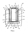
- FIG. 1 illustrates a traditional prior art VVO 2.
- Prior art VVO 2 comprises flat bottom 17, cylindrical body 12, and lid 14. Lid 14 is secured to cylindrical body 12 by bolts 18. Bolts 18 serve to restrain separation of lid 14 from body 12 if prior art VVO 2 were to tip over.
- Cylindrical body 12 has top ventilation ducts 15 and bottom ventilation ducts 16. Top ventilation ducts 15 are located at or near the top of cylindrical body 12 while bottom ventilation ducts 16 are located at or near the bottom of cylindrical body 12. Both bottom ventilation ducts 16 and top ventilation ducts 15 are located around the circumference of the cylindrical body 12. The entirety of prior art VVO 2 is positioned above grade.
- Yet another object of the present invention is to provide a system and method,for storing high level radioactive waste, such as spent nuclear fuel, that utilizes the radiation shielding properties of the subgrade during storage while providing adequate ventilation of the high level radioactive waste.
- high level radioactive waste such as spent nuclear fuel
- a further object of the present invention is to provide a system and method for storing high level radioactive waste, such as spent nuclear fuel, that provides the same or greater level of operational safeguards that are available inside a fully certified nuclear power plant structure.
- a still further object of the present invention is to provide a system and method for storing high level radioactive waste, such as spent nuclear fuel, that decreases the dangers presented by earthquakes and other catastrophic events and virtually eliminates the potential damage from a World Trade Center or Pentagon type of attack on the stored canister.
- high level radioactive waste such as spent nuclear fuel
- high level radioactive waste such as spent nuclear fuel
- Another object of the present invention is to provide a system and method for storing high level radioactive waste, such as spent nuclear fuel, below grade.
- Yet another object of the present invention is to provide a system and method of storing high level radioactive waste, such as spent nuclear fuel, that reduces the amount of radiation emitted to the environment.
- Still another object of the present invention is to provide a system and method of storing high level radioactive waste, such as spent nuclear fuel, that affords adequate heat removal capabilities from a stored canister during flood conditions, including "smart flood” conditions.
- high level radioactive waste such as spent nuclear fuel
- a system for storing high level radioactive waste comprising: a body having a cavity for receiving and storing a high level radioactive waste canister, a portion of the body positioned below grade; the body having at least one inlet ventilation duct extending from an above grade inlet to a below grade outlet in the cavity.
- the above grade inlet of the inlet ventilation duct is in a side wall of the body.
- the inlet ventilation duct can be an elongated substantially S-shape.
- two inlet ventilation ducts be provided in the body in opposing side walls of the body. Vent screens are preferably provided to cover the above grade inlets of the inlet ventilation ducts.
- the body is preferably constructed of concrete and the cavity and the ventilation duct can be insulated from the concrete body to both prevent the body from becoming heated beyond FSAR limits and to prevent the cold air entering the inlet ventilation duct from becoming heated before it enters the cavity.
- the inlet ventilation duct and the cavity are preferably built to be an integral piece that is hermetically sealed, preventing the ingress of below grade liquids. This reduces the possibility of corrosion of the internals of the cavity.
- a steel shell can be provided to line the cavity and the inlet ventilation duct can be constructed of a steel lining. The shell and the inlet ventilation duct can then be welded together to achieve the hermetic seal.
- a bottom plate that is also integral to the shell and the inlet ventilation duct can be provided below the cavity.
- the system can also comprise a base on which the body is positioned, such as a reinforced concrete slab.
- the system can also have support blocks located on the bottom/floor of the cavity.
- these support blocks will be circumferentially spaced apart and provide an inlet air plenum between a canister of high level radioactive waste and the bottom surface of the cavity when the canister is placed in the cavity for storage.
- the existence of the inlet air plenum will help facilitate optimal ventilation of the cavity.
- the support blocks can be made of low carbon steel.
- the relative height between the support blocks and the below grade outlet (i.e. the opening) of the inlet ventilation duct into the cavity will protect against overheating during flood conditions.
- the system will preferably further comprise a lid positioned atop the body and covering the cavity.
- a lid positioned atop the body and covering the cavity.
- the lid comprises a shear ring that protrudes into the cavity when the lid is positioned atop the body. The shear ring provides enormous shear resistance against lateral forces from earthquakes, impactive missiles, or other projectiles, thus, maintaining the radiation shielding integrity of the system.
- the lid also preferably comprises at least one outlet ventilation duct for allowing heated air to exit the cavity.
- This outlet ventilation duct can be, for example, a horizontal passageway in a side wall of the lid.
- the outlet ventilation ducts in the lid are circumferentially and azimuthally separated from the above grade inlet of the inlet ventilation ducts in the body. This helps prevent the heated air that exits the cavity via the lid from being drawn back into the inlet ventilation ducts in the body and back into the cavity.
- the outlet ventilation ducts can be located in the body of the VVO itself.
- a major portion of the body be positioned below grade, and more preferably that the body extend approximately less than 107cm (42 inches) above grade. It is also preferred that a major portion of the cavity's height be below grade so that when a high level radioactive waste canister is lowered into the cavity, at least a major portion of the canister is below grade. Most preferably, the entirety of the canister will be below grade during storage.
- the invention is a method of storing high level radioactive waste comprising: providing the system described above and having at least one outlet ventilation duct; lowering a high level radioactive waste into the cavity so that a major portion of the canister is below grade; and placing a lid atop the body so as to enclose the cavity; wherein ventilation of the canister is provided by cold air entering the cavity through the inlet ventilation duct in the body, the cold air being heated within the cavity by the high level radioactive waste, and warm air exiting the cavity through the outlet ventilation duct.
- the system used to perform the method of the present invention can contain any of the design particulars discussed above.
- the invention is a system for storing high level radioactive waste comprising: a body having a cavity for receiving and storing a high level radioactive waste canister, the cavity having a top, a bottom, and a bottom surface; at least one inlet ventilation duct forming a passageway from an ambient air inlet to an outlet at or near the bottom the cavity; at least one outlet ventilation duct forming a passageway from at or near the top of the cavity to ambient air; and means to support a high level radioactive waste canister in the cavity so that an air plenum is created between a bottom of the canister of high level radioactive waste and the bottom surface of the cavity; the support means supporting the high level radioactive waste canister in the cavity so that a bottom of the canister is lower than a top of the outlet.
- the support means supports the high level radioactive waste canister in the cavity so that the bottom of the canister is at least 5cm (two inches) below the top of the outlet.
- the body of the VVO can be entirely or partially above grade.
- the ambient air inlet of the inlet ventilation duct can be above grade while the outlet of the inlet ventilation duct is below grade.
- both the ambient air inlet and the outlet of the inlet ventilation duct can be above grade.
- the inlet ventilation duct will be shaped so that a line of sight does not exist to a canister supported by the support means from the ambient air inlet.
- the inlet ventilation duct can comprise a portion that is L-shaped, angled, S-shaped, or curved. This is done to prevent the radiation emitted by the canister from "shining" into the surrounding environment.
- the invention is a system for storing high level radioactive waste comprising: a shell forming a cavity for receiving a canister of high level radioactive waste, at least a portion of the shell positioned below grade; and at least one inlet ventilation duct extending from an above grade inlet to a below grade outlet at or near a bottom of the cavity; the inlet ventilation duct connected to the shell so that the cavity is hermetically sealed to ingress of below grade fluids.
- the invention is a method of storing high level radioactive waste comprising: providing a below grade hole; providing a system comprising a shell forming a cavity for receiving a canister of high level radioactive waste, at least a portion of the shell positioned below grade, and at least one inlet ventilation duct extending from an inlet to an outlet at or near a bottom of the cavity, the inlet ventilation duct connected to the shell; positioning the apparatus in the hole so the inlet of the inlet ventilation duct is above grade and the outlet of the inlet ventilation duct into the cavity is below grade; filling the hole with engineered fill; and lowering a high level radioactive waste canister into the cavity.
- the invention is a system for storing high level radioactive waste comprising: a shell forming a cavity for receiving a canister of high level radioactive waste, at least a portion of the shell positioned below grade; and at least one ventilation duct forming a passageway from at or near the top of the cavity to an ambient atmosphere; wherein the cavity is hermetically sealed to ingress of below grade fluids.
- the invention is a method of storing low heat high level radioactive waste comprising: providing a system comprising a shell forming a cavity for receiving a canister of high level radioactive waste, at least a portion of the shell positioned below grade, and at least one ventilation duct forming a passageway from at or near the top of the cavity to an ambient atmosphere; wherein the cavity is hermetically sealed to ingress of below grade fluids; and lowering a canister of low heat high level radioactive waste into the cavity until at least a major portion of the canister is below grade.
- Figure 1 is a top perspective view of a prior art VVO.
- Figure 2 is a side cross sectional view of an underground VVO according to an embodiment of the present invention having a spent fuel canister positioned therein.
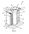
- Figure 3 is a perspective view of the underground VVO of FIG. 2 removed from the ground.
- Figure 4 is a bottom perspective view of an alternate embodiment of a lid to be used with the underground VVO of FIG. 2 .
- Figure 5 is a perspective view of an array of underground VVO's according to an embodiment of the present invention stored at an ISFSI.
- Figure 6 is a side cross sectional view of area VI-VI of FIG. 2 .
- Figure 7 is a top view of the underground VVO of FIG. 2 removed from the ground and with the spent fuel canister removed from the cavity and the lid removed.
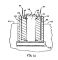
- Figure 8A is a schematic cross-sectional view of an underground VVO according to an embodiment of the present invention having a first alternative configuration of the inlet and outlet ventilation ducts.
- Figure 8B is a schematic cross-sectional view of an underground VVO according to an embodiment of the present invention having a second alternative configuration of the inlet and outlet ventilation ducts.
- Figure 8C is a schematic cross-sectional view of an underground VVO according to an embodiment of the present invention having a third alternative configuration of the inlet and outlet ventilation ducts.
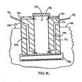
- Figure 8D is a schematic cross-sectional view of an underground VVO according to an embodiment of the present invention wherein the body of the underground VVO is substantially flush with the ground.
- Figure 8E is a schematic cross-sectional view of an underground VVO according to an embodiment of the present invention wherein the body of the underground VVO is substantially flush with the ground and having an alternative configuration of the inlet and outlet ventilation ducts.
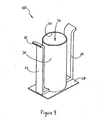
- Figure 9 is a top perspective view of an integral structure for storing spent nuclear fuel according to an embodiment of the present invention.
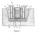
- Figure 10 is a schematic of the integral structure of FIG. 9 lowered into a below grade hole and positioned atop a base.
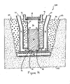
- Figure 11 is a schematic of the arrangement of FIG. 10 wherein the below grade hole is being filled with soil.
- Figure 12 is a schematic illustrating the arrangement of FIG. 10 wherein the below grade hole is completely filled with soil.
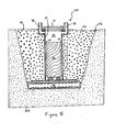
- Figure 13 is a schematic illustrating the arrangement of FIG. 12 wherein a spent fuel canister is loaded in the integral structure and a lid positioned thereon.
- Figure 14 is a schematic view of an integral structure according to an embodiment of the present invention having an alternative configuration for the inlet and outlet ventilation ducts.
- Figure 15 is a schematic view of an integral structure for storing low heat spent fuel according to an embodiment of the present invention free of inlet ventilation ducts.
- Underground VVO 20 is illustrated according to a first embodiment of the present invention.
- Underground VVO 20 is a vertical, ventilated dry spent fuel storage system that is fully compatible with 100 ton and 125 ton transfer casks for spent fuel canister transfer operations.
- Underground VVO 20 can be modified/designed to be compatible with any size or style transfer cask.
- Underground VVO 20 is designed to accept spent fuel canisters for storage at an Independent Spent Fuel Storage Installation ("ISFSI") in lieu of above ground overpacks (such as prior art VVO 2 in FIG. 1 ). All spent fuel canister types engineered for storage in free-standing and anchored overpack models can be stored in underground VVO 20.
- ISFSI Independent Spent Fuel Storage Installation
- canister broadly includes any spent fuel containment apparatus, including, without limitation, multi-purpose canisters and thermally conductive casks.
- spent fuel is transferred and stored in metal casks having a honeycomb grid-work/basket built directly into the metal cask.
- casks and similar containment apparatus qualify as canisters, as that term is used herein, and can be used in conjunction with underground VVO 20 as discussed below
- Underground VVO 20 comprises body 21, base 22, and removable lid 41.
- Body 21 is constructed of concrete, but can be constructed of other suitable materials.
- Body 21 is rectangular in shape but can be any shape, such as for example, cylindrical, conical, spherical, semi-spherical, triangular, or irregular in shape.
- a portion of body 21 is positioned below grade so that only top portion 24 protrudes above grade level 23.
- top portion 24 of body 21 extends above ground level 23 can be varied greatly and will depend on a multitude of design considerations, such as canister dimensions, radioactivity levels of the spent fuel to be stored, ISFSI space limitations, geographic location considering susceptibility to missile-type and ground attacks, geographic location considering frequency of and susceptibility to natural disasters (such as earthquakes, floods, tornadoes, hurricanes, tsunamis, etc.), environmental conditions (such as temperature, precipitation levels), and/or ground water levels.
- top portion 24 of body 21 is less than approximately 107cm (42 inches) above ground level 23, and most preferably approximately 15 to 91cm (6 to 36 inches) above ground level 23.
- the entire height of body 21 be below grade (illustrated in FIGS. 8D and 8E ). As will be discussed in more detail below, when the entire height of body is below grade, only the top surface of the body will be exposed to the ambient air above grade.
- body 21 forms cylindrical cavity 26 therein (best shown in FIG. 3 ). While cavity 26 is cylindrical in shape, cavity 26 is not limited to any specific size, shape, and/or depth and can be designed to receive and store almost any shape of canister without departing from the spirit of the invention. While not necessary to practice the invention, it is preferred that the horizontal cross-sectional size and shape of cavity 26 be designed to generally correspond to the horizontal cross-sectional size and shape of the canister-type that is to be used in conjunction with that particular underground VVO.
- cavity 26 it is desirable that the size and shape of cavity 26 be designed so that when a spent fuel canister (such as canister 70 ) is positioned in cavity 26 for storage, a small clearance exists between the outer side walls of the canister and the side walls of cavity 26.
- a spent fuel canister such as canister 70
- This small clearance also facilitates flow of the heated air during spent nuclear fuel cooling.
- the exact size of the clearance can be controlled/designed to achieve the desired fluid flow dynamics and heat transfer capabilities for any given situation. In some embodiments, for example, the clearance may be 2.5 to 7.5cm (1 to 3 inches). A small clearance also reduces radiation streaming.
- Inlet ventilation ducts 25 are provided in body 21 for providing inlet ventilation to the bottom of cavity 26.
- Inlet ventilation ducts 25 are elongated substantially S-shaped passageways extending from above grade inlets 27 to below grade outlets 28.
- Above grade inlets 27 are located on opposing side walls of top portion 24 of body 21 and open to the ambient air above ground level 23.
- ambient air, ambient atmosphere, or outside atmosphere refer to the atmosphere/air external to the underground VVO, and include the natural outside environment and spaces within buildings, tents, caves, tunnels, or other man-made or natural enclosures.
- inlet ventilation ducts 25 provide a passageway for the inlet of ambient air to the bottom of cavity 26, despite the bottom of cavity 26 being well below grade.
- Vent screens 31 FIG. 3
- above grade inlets 27 cease to be a location of elevated dose rate that is common in free-standing above ground VVOs.
- below grade outlets 28 are illustrated as being opening near the bottom of the walls of cavity 26, below grade outlets 28 can be located in the floor of cavity 26 is desired. This can be accomplished by appropriately reshaping inlet ventilation ducts 25 and forming an opening through bottom plate 38 and into cavity 26.
- base 22 can be considered part of the body 21 through which the inlet ventilation ducts 25 extend.
- Above grade inlets 27 are located in the side walls of body 21 at an elevation of about 25cm (10 inches) above ground level 23.
- the inlets 27 can be located at any desired elevation above the ground level, including level/flush therewith, as shown in FIGS. 8D and 8E . Elevating above grade inlets 27 substantially above the ground level 23 helps reduce the likelihood that rain or flood water will enter the cavity 26. It is noted that for IFSI's in flood zones, floodwater can possibly rise more than a foot above ground level and, thus, enter cavity 26 via inlet ventilation ducts 25. However, as discussed below with respect to FIG. 6 , underground VVO 20 is specifically designed to deal with the worst flood conditions in a safe and effective manner.
- above grade inlets 27 are preferably located in the side walls of body 21, the above grade inlets are not limited to such a location and, if desired, can be located anywhere on the body, including for example in the top surface (or any other surface) of the body. Further examples of possible locations for above grade inlets 27 on body 21 are illustrated in FIGS. 8A-8E .
- inlet ventilation ducts 25 have a rectangular cross-sectional area of about 15cm by 102cm (6 inches by 40 inches). However, any cross-sectional shape and/or size can be used, such as for example, round, elliptical, triangular, hexagonal, octagonal, etc. Additionally, while the shape of inlet ventilation ducts 25 is an elongated substantially S-shaped passageway, a multitude of shapes can be used that still achieve acceptable dose rates at the above grade inlets 27.
- the inlet ventilation duct can extend from the above grade inlet to the below grade outlet in a zig-zag shape, a tilted linear shape, a general L-shape, or any angular, linear, or curved combination.
- inlet ventilation duct The exact shape, size, and cross-sectional configuration of the inlet ventilation duct is a matter of design preference and will be dictated by such factors, such as thickness of the body of the VVO, radioactivity level of the spent fuel being stored in the cavity, temperature of the spent fuel canister, desired fluid flow dynamics through the ducts, and placement of the above grade inlet vents on the body (i.e., whether the above grade inlet vents/opening are located on the side walls of the body, its top surface, or some other surface of the body). Further examples of possible shapes for inlet ventilation ducts 25 are illustrated in FIGS. 8A-8E .
- Inlet ventilation ducts 25 are preferably formed by a low carbon steel liner. However, inlet ventilation ducts 25 can be made of any material or can be mere passageways formed into concrete body 21 without a lining.
- the integral structure itself is an invention and can be used to store spent nuclear fuel without the use of body 21.
- An appropriate preservative such as a coal tar epoxy or the like, is applied to the exposed surfaces of shell 34, bottom plate 38, and inlet ventilation ducts 25 in order to ensure sealing, to decrease decay of the materials, and to protect against fire.
- a suitable coal tar epoxy is produced by Carboline Company out of St. Louis, Missouri under the tradename Bitumastic 300M.
- a bottom plate will not be used.
- Concrete body 21 surrounds shell 34 and inlet ventilation ducts 25.
- Body 21 provides non-structural protection for shell 34 and inlet ventilation ducts 25.
- Insulation 37 is provided at the interface between shell 34 and concrete body 21 and at the interface between inlet ventilation ducts 25 and concrete body 21. Insulation 37 is provided to prevent excessive transmission of heat decay from spent fuel canister 70 to concrete body 21, thus maintaining the bulk temperature of the concrete within FSAR limits. Insulating shell 34 and inlet ventilation ducts 25 from concrete body 21 also serves to minimize the heat-up of the incoming cooling air before it enters cavity 26.
- Suitable forms of insulation include, without limitation, blankets of alumina-silica fire clay (Kaowool Blanket), oxides of alimuna and silica (Kaowool S Blanket), alumina-silica-zirconia fiber (Cerablanket), and alumina-silica-chromia (Cerachrome Blanket).
- Insulating inlet ventilation ducts 25 from the heat load of spent fuel in cavity 26 is very important in facilitating and maintaining adequate ventilation/cooling of the spent fuel.
- the insulating process can be achieved in a variety of ways, none of which are limiting of the present invention.
- the gap may be filled with an inert gas or air if desired.
- the insulating means is not limited to being positioned on the outside surfaces of shell 34 or inlet ventilation ducts 25 but can be positioned anywhere between cavity 26 and inlet ventilation ducts 25.
- Base 22 is a reinforced concrete slab designed to satisfy the load combinations of recognized industry standards, such as, without limitation, ACI-349.
- Base 22 is rectangular in shape but can take on any shape necessary to support body 21, such as round, elliptical, triangular, hexagonal, octagonal, irregularly shaped, etc. While using a base is preferable to achieve adequate load supporting requirements, situations can arise where using such a base may be unnecessary.
- underground VVO 20 has a removable ventilated lid 41.
- Lid 41 is positioned atop body 21, thereby substantially enclosing cavity 26 so that radiation does not escape through the top of cavity 26 when canister 70 is positioned in cavity 26.
- outlet air plenum 36 is formed between the top surface of canister 70 and lid 41.
- Outlet air plenum 36 is preferably a minimum of 7.5cm (3 inches) in height, but can be any desired height. The exact height will be dictated by design considerations such as desired fluid flow dynamics, canister height, VVO height, the depth of the cavity, canister heat load, etc.
- Lid 41 has four outlet ventilation ducts 42.
- Outlet ventilation ducts 42 form a passageway from the top of cavity 26 (specifically from outlet air plenum 36 ) to the ambient air so that heated air can escape from cavity 26.
- Outlet ventilation ducts 42 are horizontal passageways that extend through side wall 30 of lid 41.
- the outlet ventilation ducts can be any shape or orientation, such as vertical, L-shaped, S-shaped, angular, curved, etc. Because outlet ventilation ducts 42 are located within lid 41 itself, the total height of body 21 is minimized.
- Lid 41 comprises a roof 35 made of concrete. Roof 35 provides radiation shielding so that radiation does not escape from the top of cavity 26. Side wall 30 of lid 41 is an annular ring. Outlet air plenum 36 helps facilitate the removal of heated air via outlet ventilation ducts 42. In order to minimize the heated air exiting outlet ventilation ducts 42 from being siphoned back into inlet ventilation ducts 25, outlet ventilation ducts 42 are azimuthally and circumferentially separated from inlet ventilation ducts 25.
- Ventilated lid 41 also comprises shear ring 47.
- shear ring 47 protrudes into cavity 26, thus, providing enormous shear resistance against lateral forces from earthquakes, impactive missiles, or other projectiles.
- Lid 41 is secured to body 21 with bolts (not shown) that extend therethrough.
- duct photon attenuators be inserted into all of inlet ventilation ducts 25 and/or outlet ventilation ducts 42 of underground VVO 20, irrespective of shape and/or size.
- a suitable duct photon attenuator is described in United States Patent 6,519,307, Bongrazio , the teachings of which are incorporated herein by reference.
- Lid 50 contains similar design aspects as lid 41 and is illustrated to more fully disclose the aforementioned lid design aspects.
- Lid 50 has four horizontal outlet ventilation ducts 51 in side wall 52.
- Shear ring 54 is provided on the bottom of lid 50 to fit into cavity 26.
- Bolts 18 are used to secure lid 50 to tapped holes in the top of body 21.
- outlet ventilation ducts are illustrated as being located within the lid 50 of underground VVO 20, the present invention is not so limited.
- outlet ventilation ducts can be located in the body of the underground VVO at a location above grade. This concept is illustrated if FIGS . 8A-8E .
- the openings of the outlet ventilation ducts to the ambient air can be located in the body's side walls, on its top surface, or in any other surface. Similar to when the outlet ventilation ducts are located in the lid, the outlet ventilation ducts can take on a variety of shapes and/or configurations when located in the body of the underground VVO itself.
- the outlet ventilation ducts are preferably formed by a low carbon steel liner, but can be made of any material or can be mere passageways formed into concrete body 21 or lid 41 without a lining.
- the outlet ventilation duct openings be azimuthally and circumferentially separated from the inlets of the inlet ventilation ducts to minimize interaction between inlet and outlet air streams.
- soil 29 surrounds body 21 for almost the entirety of its height.
- spent fuel canister 70 is positioned in cavity 26, at least a major portion, if not the entirety, of canister 70 is below grade.
- the entire height of canister 70 is below grade in order to take full advantage of the shielding effect of the soil 29.
- soil 29 provides a degree of radiation shielding for spent fuel stored in underground VVO 20 that can not be achieved in above-ground overpacks.
- Underground VVO 20 is unobtrusive in appearance and there is no danger of underground VVO 20 tipping over. Additionally, underground VVO 20 does not have to contend with soil-structure interaction effects that magnify the free-field acceleration and potentially challenge the stability of an above ground free-standing overpack.
- FIG. 6 illustrates design aspects that are important to ensure that underground VVO 20 can successfully withstand flood conditions without adverse impact.
- Support blocks 32 are provided on the bottom surface (formed by plate 38 ) of cavity 26 so that canister 70 can be placed thereon. Support blocks 32 are circumferentially spaced from one another (shown in FIG. 7 ).
- the bottom surface 71 of canister 70 rests on support bocks 32, forming an inlet air plenum 33 between the bottom surface 71 of the canister 70 and the bottom surface/floor of cavity 26.
- Support blocks 32 are made of low carbon steel and are preferably welded to the bottom surface of the cavity 26. Other suitable materials of construction include, without limitation, reinforced-concrete, stainless steel, and other metal alloys.
- Support blocks 32 also serve an energy/impact absorbing function .
- Support blocks 32 are preferably of a honeycomb grid style, such as those manufactured by Hexcel Corp., out of California, U.S.
- Support blocks 32 are specifically designed so that bottom surface 71 of canister 70 is lower than top 74 of below grade outlets 28 ( FIG. 2 ) of inlet ventilation ducts 25. Preferably, support blocks 32 are designed so that bottom surface 71 of canister 70 is about 5 to 15cm (2 to 6 inches) below top 74 of below grade outlets 28. However, any desired height differential can be achieved through proper design.
- VVO 20 By supporting canister 70 in cavity 26 so that its bottom surface 71 is lower than top 74 of below grade outlets 28, underground VVO 20 will provide adequate cooling to canister 70 under even the most adverse flood condition, which is colloquially referred to as a "smart flood.”
- a “smart flood” is one that floods the VVO so that the water level is just high enough to block airflow though the inlet ventilation ducts 25 completely. In other words, the water level is just even with top 74 of the below grade outlets 28.
- underground VVO 20 can adequately deal with the "smart flood” condition because the bottom surface 71 of the canister 70 is situated at a height that is below top 74 of below grade outlets 28.
- the bottom of the canister 70 will be in contact with (i.e. submerged in) the water. Because the heat removal efficacy of water is over 100 times that of air, a wet bottom is all that is needed to effectively remove heat and keep the canister 70 cool. The deeper the submergence of canister 70 in the water, the cooler canister 70 and its contained fuel will remain.
- the canister cooling action changes from ventilation air-cooling to evaporative water cooling.
- below grade outlets 28 of inlet ventilation ducts 25 will be 10cm (8 inches) high by 102cm (40 inches) wide and inlet air plenum 33 is 15cm (6 inches) high. This provides a height differential of 5cm (2 inches).
- the inlet ventilation ducts When incorporated into above ground VVOs, the inlet ventilation ducts should be designed so that radiation can not escape to the surrounding environment from the inlet ventilation ducts. This is a threat because the canister will be below the inlet duct's opening into the storage cavity.
- the inlet ventilation ducts will be shaped so that a line of sight does not exist to the canister in the storage cavity from the ambient air.
- the inlet ventilation ducts can comprise a portion that is L-shaped, angled, S-shaped, or curved.
- canister 70 will be positioned in cavity 26 and rest directly on the floor of cavity 26.
- support blocks 32 is desirable because of the creation of air inlet plenum 33 and because the use of support blocks 32 helps prohibit debris and dirt from getting trapped at the bottom of cavity 26.
- FIGS. 8A-8E examples of alternative configurations of the outlet ventilation ducts and the inlet ventilation ducts in an underground VVO according to the present invention are schematically illustrated. Much of the detail, and some structure, has been omitted in FIGS. 8A-8E for simplicity with the understanding that any or all of the details discussed above with respect to underground VVO 20 can be incorporated therein. Like numbers are used to identify like parts with the exception of alphabetical suffixes being used for each embodiment.
- the heated air exiting the outlet ventilation ducts 42 be prohibited from being siphoned back into the inlet ventilation ducts 25 (i.e., keeping the warm outlet air stream from mixing with the cool inlet air stream).
- This can be accomplished by in a number of ways, including: (1) the positioning/placement of the inlets 27 on the underground VVO 20 with respect to the outlets of the outlet ventilation ducts 42; providing a plate 98 or other structure that segregates the air streams (as exemplified in FIGS. 8A and 8C-8E ); and/or (3) extending the inlet ventilation ducts 25 to a position away from the outlet ventilation ducts 42.
- ISFIs can be designed to employ any number of underground VVOs 20 (or integral structures 100 ) and can be expanded in number easily to meet growing needs. Although underground VVOs 20 are closely spaced, the design permits any cavity to be independently accessed by cask crawler 90 with ease. The subterranean configuration of underground VVOs 20 greatly reduce the height of the stack structures created during loading/transfer procedures where transfer cask 80 is positioned atop underground VVO 20.
- FIGS. 2-5 An embodiment of a method of using underground VVO 20 to store spent nuclear fuel canister 70 will now be discussed in relation to FIGS. 2-5 .
- spent fuel canister 70 Upon being removed from a spent fuel pool and treated for dry storage, spent fuel canister 70 is positioned in transfer cask 80.
- Transfer cask is 80 is carried by cask crawler 90 to a desired underground VVO 20 for storage. While a cask crawler is illustrated, any suitable means of transporting transfer cask 80 to a position above underground VVO 20 can be used.
- any suitable type of load-handling device such as without limitation, a gantry crane, overhead crane, or other crane device can be used.
- lid 41 is removed from body 21 so that cavity 26 is open.
- Cask crawler 90 positions transfer cask 80 atop underground VVO 20. After transfer cask is properly secured to the top of underground VVO 20, a bottom plate of transfer cask 80 is removed. If necessary, a suitable mating device can be used to secure the connection of transfer cask 80 to underground VVO 20 and to remove the bottom plate of transfer cask 80 to an unobtrusive position. Such mating devices are well known in the art and are often used in canister transfer procedures. Canister 70 is then lowered by cask crawler 90 from transfer cask 80 into cavity 26 of underground VVO 20 until the bottom surface of canister 70 contacts and rests atop support blocks 32, as described above.
- canister 70 When resting on support blocks 32, a major portion of the canister's height is below grade. Most preferably, the entirety of canister 70 is below grade when in its storage position.
- lid 41 is placed over cavity 26, substantially enclosing cavity 26. Lid 41 is oriented atop body 21 so that shear ring 47 protrudes into cavity 26 and outlet ventilation ducts 42 are azimuthally and circumferentially separated from inlet ventilation ducts 25 on body 21. Lid 41 is then secured to body 21 with bolts.
- cool air from the ambient is siphoned into inlet ventilation ducts 25 and into the bottom of cavity 26. This cool air is then warmed by the heat from the spent fuel in canister 70, rises in cavity 26 via annular space 60 ( FIG. 6 ) around canister 70, and then exits cavity 26 as heated air via outlet ventilation ducts 42 in lid 41.
- Integral structure 100 for storing spent nuclear fuel is illustrated according to an embodiment of the invention.
- Integral structure 100 is essentially a combination of shell 34, inlet ventilation ducts 25, and bottom plate 38 of underground VVO 20 without the concrete body.
- Integral shell 100 can be used to store canisters of spent nuclear fuel without the addition of the concrete body. Therefore, some embodiments of the present invention will be the integral structure 100 itself.
- Shell 34, bottom plate 38, and inlet ventilation ducts 25 are preferably formed of a metal, such as low carbon steel.
- suitable materials include, without limitation, stainless steel, aluminum, aluminum-alloys and plastics.
- Inlet ventilation ducts 25, bottom plate 38, and shell 34 are seal welded at all junctures to form a unitary structure that is hermetically sealed to the ingress water and other fluids.
- the only way water or other fluids can enter cavity 26 is through inlets 27 or top opening 101 of shell 34.
- the height of shell 34 is designed so that a canister of spent fuel can be positioned within cavity 26 so as not to protrude from top opening 101. There is no limitation on the height to which shell 34 can be constructed.
- shell 34 The exact height of shell 34 will be dictated by the height of the spent fuel canister to be stored therein, the desired depth (below grade) at which the canister is to be stored, whether the outlet ventilation ducts are in the lid or integrated into the shell 34, and/or the desired height of the outlet air plenum that is to exist during canister storage.
- FIGS. 10-13 illustrate a process of using integral structure 100 to store a spent fuel canister at a below grade position at an ISFSI, or other location, according to one embodiment of the present invention.
- integral structure 100 such as, for example, the use of vent screens, variable configurations of the inlet and outlet ducts, clearances, the use of an insulation, etc.
- vent screens variable configurations of the inlet and outlet ducts
- clearances the use of an insulation, etc.
- a discussion of these details will be omitted with the understanding that any or all of the details of underground VVO 20 are (or can be) incorporated into the storing methods and apparatus of integral structure 100, and vice versa.
- a hole 200 is first dug into the ground 210 at a desired position within the ISFSI and at a desired depth. Once hole 200 is dug, and its bottom properly leveled, base 22 is placed at the bottom of hole 200.
- Base 22 is a reinforced concrete slab designed to satisfy the load combinations of recognized industry standards, such as ACI- 349. However, in some embodiments, depending on the load to be supported and/or the ground characteristics, the use of a base may be unnecessary.
- integral structure 100 is lowered into the hole 200 in a vertical orientation until it rests atop base 22.
- Bottom plate 38 of integral structure 100 contacts and rests atop the top surface of base 22. If desired, the bottom plate 38 can be bolted or otherwise secured to the base 22 at this point to prohibit future movement of the integral structure 100 with respect to the base 22.
- soil supply pipe 300 is moved into position above hole 200.
- Soil 301 is delivered into hole 200 exterior of integral structure 100, thereby filling hole 200 with soil 301 and burying a portion of the integral structure 100.
- soil 301 is exemplified to fill hole 200
- any suitable engineered fill can be used that meets environmental and shielding requirements.
- Other suitable engineered fills include, without limitation, gravel, crushed rock, concrete, sand, and the like.
- the desired engineered fill can be supplied to the hole by any means feasible, including manually, dumping, and the like.
- soil 301 is supplied to hole 200 until soil 301 surrounds integral structure 100 and fills hole 200 to a level where soil 301 is approximately equal to ground level 212.
- Soil 301 is in direct contact with the exterior surfaces of integral structure 100 that are below grade.
- inlets 27 of inlet ventilation ducts 25 are above grade.
- Shell 34 also protrudes from soil 301 so that opening 101 is slightly above grade. Therefore, because integral structure 100 is hermetically sealed at all junctures, below grade liquids and soil can not enter into cavity 26 or inlet ventilation ducts 25.
- Support blocks 32 are provided at the bottom of cavity 26 for supporting a stored spent fuel canister.
- canister 70 When canister 70 is supported on support blocks 32, the entire height of canister 70 is below ground level 212. This maximizes use of the ground's radiation shielding capabilities. The depth at which canister 70 is below ground level 212 can be varied by increasing or decreasing the depth of hole 200.
- Lid 41 comprises outlet ventilation ducts 42.
- Outlet ventilation ducts 42 form passageways from outlet air plenum 36, through lid 41, to the ambient air above ground level 212.
- Outlet ventilation ducts 42 do not have to be provided in lid 41, but can be formed as part of the integral structure 100 if desired. This will be discussed in greater detail below with respect to FIG. 14 .
- the radiation shielding effect of the sub-grade is utilized while adequately facilitating cooling of canister 70.
- the cooling of canister 70 is facilitated by cool air entering inlet ventilation ducts 25 via above grade inlets 27.
- the cool air travels through inlet ventilation ducts 25 until it enters cavity 26 at or near inlet air plenum 33 via below grade outlets 28.
- Once the cool air is within cavity 26 it is warmed by the heat emanating from canister 70.
- the air As the air is warmed, it travels upward along the outer surface of canister 70 via annular space 60 until the air enters outlet air plenum 36.
- As the air travels upward through annular space 60 it continues to remove heat from canister 70.
- the warmed air then exits cavity 26 via outlet ventilation ducts 42 and enters the ambient air. This natural convective cooling flow repeats continuously until the canister 70 is adequately cooled.
- Integral structure 200 is used to store a spent fuel canister in manner similar to that of integral structure 100 discussed above. While much of the structure is identical to that of integral structure 100, integral structure 200 further comprises outlet ventilation ducts 42 seal welded directly to shell 34.
- the outlet ventilation ducts 42 can be formed out of any of the materials discussed above with respect to the inlet ventilation ducts 25.
- lid 41 can be free of such ducts. The cooling process of canister 70 remains the same.
- FIG. 15 illustrates an integral structure 300 according to another aspect of the present invention.
- Integral structure 300 is similar in many respect to that of integral structures 100 and 200 in its design and functioning. However, integral structure 300 is specifically designed to store canisters 70 holding low heat spent fuel. When a canister 70 is giving off low heat, for example in the magnitude of 2-3 kW, it is not necessary to supply inlet ventilation ducts to supply cool air to cavity 26. Therefore, the inlet ventilation ducts are omitted from integral structure 300. Integral structure 300 comprises only outlet ventilation ducts 42, which act as both an inlet for the cooler air and an outlet for the warmer air.
- outlet ventilation ducts 42 of integral structure 300 are seal welded to shell 34, it is possible for the outlet ventilation ducts to be located in the lid 41 if desired.
- the concept of eliminating the inlet ventilation ducts for low heat load canister storage can be applied to any of the underground or above ground VVO embodiments illustrated in this application, specifically including underground VVO 20 and it derivatives.
Landscapes
- Engineering & Computer Science (AREA)
- Physics & Mathematics (AREA)
- General Engineering & Computer Science (AREA)
- High Energy & Nuclear Physics (AREA)
- Life Sciences & Earth Sciences (AREA)
- Environmental Sciences (AREA)
- Environmental & Geological Engineering (AREA)
- Birds (AREA)
- Animal Husbandry (AREA)
- Biodiversity & Conservation Biology (AREA)
- Filling Or Discharging Of Gas Storage Vessels (AREA)
- Processing Of Solid Wastes (AREA)
- Gasification And Melting Of Waste (AREA)
Abstract
Description
- The present application claims priority to United States Patent Application
11/054,869, filed February 10, 2005 11/054,897, filed February 10, 2005 11/054,898, filed February 10, 2005 10/803,620, filed March 18, 2004 - The present invention related generally to the field of storing high level radioactive waste, and specifically to systems and methods for storing high level radioactive waste, such as spent nuclear fuel, in ventilated vertical modules.
- In the operation of nuclear reactors, it is customary to remove fuel assemblies after their energy has been depleted down to a predetermined level. Upon removal, this spent nuclear fuel is still highly radioactive and produces considerable heat, requiring that great care be taken in its packaging, transporting, and storing. In order to protect the environment from radiation exposure, spent nuclear fuel is first placed in a canister. The loaded canister is then transported and stored in large cylindrical containers called casks. A transfer cask is used to transport spent nuclear fuel from location to location while a storage cask is used to store spent nuclear fuel for a determined period of time.
- In a typical nuclear power plant, an open empty canister is first placed in an open transfer cask. The transfer cask and empty canister are then submerged in a pool of water. Spent nuclear fuel is loaded into the canister while the canister and transfer cask remain submerged in the pool of water. Once fully loaded with spent nuclear fuel, a lid is typically placed atop the canister while in the pool.. The transfer cask and canister are then removed from the pool of water, the lid of the canister is welded thereon and a lid is installed on the transfer cask. The canister is then properly dewatered and filled with inert gas. The transfer cask (which is holding the loaded canister) is then transported to a location where a storage cask is located. The loaded canister is then transferred from the transfer cask to the storage cask for long term storage. During transfer from the transfer cask to the storage cask, it is imperative that the loaded canister is not exposed to the environment. cask to the storage cask, it is imperative that the loaded canister is not exposed to the environment.
- One type of storage cask is a ventilated vertical overpack ("VVO"). A VVO is a massive structure made principally from steel and concrete and is used to store a canister loaded with spent nuclear fuel. VVOs stand above ground and are typically cylindrical in shape and extremely heavy, weighing over 150 tons and often having a height greater than 4.9m (16 feet). VVOs typically have a flat bottom, a cylindrical body having a cavity to receive a canister of spent nuclear fuel, and a removable top lid.
- In using a VVO to store spent nuclear fuel, a canister loaded with spent nuclear fuel is placed in the cavity of the cylindrical body of the VVO. Because the spent nuclear fuel is still producing a considerable amount of heat when it is placed in the VVO for storage, it is necessary that this heat energy have a means to escape from the VVO cavity. This heat energy is removed from the outside surface of the canister by ventilating the VVO cavity. In ventilating the VVO cavity, cool air enters the VVO chamber through bottom ventilation ducts, flows upward past the loaded canister, and exits the VVO at an elevated temperature through top ventilation ducts. The bottom and top ventilation ducts of existing VVOs are located circumferentially near the bottom and top of the VVO's cylindrical body respectively, as illustrated in
FIG. 1 . - While it is necessary that the VVO cavity be vented so that heat can escape from the canister, it is also imperative that the VVO provide adequate radiation shielding and that the spent nuclear fuel not be directly exposed to the external environment. The inlet duct located near the bottom of the overpack is a particularly vulnerable source of radiation exposure to security and surveillance personnel who, in order to monitor the loaded overpacks, must place themselves in close vicinity of the ducts for short durations.
- Additionally, when a canister loaded with spent nuclear fuel is transferred from a transfer cask to a storage VVO, the transfer cask is stacked atop the storage VVO so that the canister can be lowered into the storage VVO's cavity. Most casks are very large structures and can weigh up to 250,000 lbs. and have a height of 4.9m (16 ft). or more. Stacking a transfer cask atop a storage VVO/cask requires a lot of space, a large overhead crane, and possibly a restraint system for stabilization. Often, such space is not available inside a nuclear power plant. Finally, above ground storage VVOs stand at least 16 feet above ground, thus, presenting a sizable target of attack to a terrorist.
-
FIG. 1 illustrates a traditional prior art VVO 2. Prior art VVO 2 comprisesflat bottom 17,cylindrical body 12, andlid 14.Lid 14 is secured tocylindrical body 12 bybolts 18.Bolts 18 serve to restrain separation oflid 14 frombody 12 ifprior art VVO 2 were to tip over.Cylindrical body 12 hastop ventilation ducts 15 andbottom ventilation ducts 16.Top ventilation ducts 15 are located at or near the top ofcylindrical body 12 whilebottom ventilation ducts 16 are located at or near the bottom ofcylindrical body 12. Bothbottom ventilation ducts 16 andtop ventilation ducts 15 are located around the circumference of thecylindrical body 12. The entirety of prior art VVO 2 is positioned above grade. - It is an object of the present invention to provide a system and method for storing high level radioactive waste, such as spent nuclear fuel, that reduces the height of the stack assembly when a transfer cask is stacked atop a storage VVO.
- It is another object of the present invention to provide a system and method for storing high level radioactive waste, such as spent nuclear fuel, that requires less vertical space.
- Yet another object of the present invention is to provide a system and method,for storing high level radioactive waste, such as spent nuclear fuel, that utilizes the radiation shielding properties of the subgrade during storage while providing adequate ventilation of the high level radioactive waste.
- A further object of the present invention is to provide a system and method for storing high level radioactive waste, such as spent nuclear fuel, that provides the same or greater level of operational safeguards that are available inside a fully certified nuclear power plant structure.
- A still further object of the present invention is to provide a system and method for storing high level radioactive waste, such as spent nuclear fuel, that decreases the dangers presented by earthquakes and other catastrophic events and virtually eliminates the potential damage from a World Trade Center or Pentagon type of attack on the stored canister.
- It is also an object of the present invention to provide a system and method for storing high level radioactive waste, such as spent nuclear fuel, that allows an ergonomic transfer of the high level radioactive waste from a transfer cask to a storage VVO.
- Another object of the present invention is to provide a system and method for storing high level radioactive waste, such as spent nuclear fuel, below grade.
- Yet another object of the present invention is to provide a system and method of storing high level radioactive waste, such as spent nuclear fuel, that reduces the amount of radiation emitted to the environment.
- Still another object of the present invention is to provide a system and method of storing high level radioactive waste, such as spent nuclear fuel, that affords adequate heat removal capabilities from a stored canister during flood conditions, including "smart flood" conditions.
- These and other objects are met by the present invention which in one aspect is a system for storing high level radioactive waste comprising: a body having a cavity for receiving and storing a high level radioactive waste canister, a portion of the body positioned below grade; the body having at least one inlet ventilation duct extending from an above grade inlet to a below grade outlet in the cavity. By providing an inlet ventilation duct in the body that extends from above grade to the cavity at a point below grade, the radiation shielding properties of the subgrade can be utilized for the high level radioactive waste canister without obstructing the ventilation of the canister in the cavity with ambient air. When loaded with a hot high level radioactive waste, cool ambient air will enter the above grade inlet, travel through the inlet ventilation duct, and enter the cavity preferably, at or near its bottom. Heat from the high level radioactive waste will warm the cool air causing it to rise within the cavity. The heated air will then exit the cavity via an outlet ventilation duct located in either a lid or in an above grade opening in the body. Thus, below grade storage of the high level radioactive waste canister is facilitated while affording adequate heat ventilation for the high level radioactive waste.
- Preferably, the above grade inlet of the inlet ventilation duct is in a side wall of the body. When the above grade inlet is in the side wall of the body, the inlet ventilation duct can be an elongated substantially S-shape. In order to provide sufficient ventilation, it is preferred that two inlet ventilation ducts be provided in the body in opposing side walls of the body. Vent screens are preferably provided to cover the above grade inlets of the inlet ventilation ducts.
- The body is preferably constructed of concrete and the cavity and the ventilation duct can be insulated from the concrete body to both prevent the body from becoming heated beyond FSAR limits and to prevent the cold air entering the inlet ventilation duct from becoming heated before it enters the cavity. The inlet ventilation duct and the cavity are preferably built to be an integral piece that is hermetically sealed, preventing the ingress of below grade liquids. This reduces the possibility of corrosion of the internals of the cavity. In this embodiment, a steel shell can be provided to line the cavity and the inlet ventilation duct can be constructed of a steel lining. The shell and the inlet ventilation duct can then be welded together to achieve the hermetic seal. A bottom plate that is also integral to the shell and the inlet ventilation duct can be provided below the cavity. The system can also comprise a base on which the body is positioned, such as a reinforced concrete slab.
- The system can also have support blocks located on the bottom/floor of the cavity. Preferably, these support blocks will be circumferentially spaced apart and provide an inlet air plenum between a canister of high level radioactive waste and the bottom surface of the cavity when the canister is placed in the cavity for storage. The existence of the inlet air plenum will help facilitate optimal ventilation of the cavity. The support blocks can be made of low carbon steel. As discussed below, in some aspects of the invention, the relative height between the support blocks and the below grade outlet (i.e. the opening) of the inlet ventilation duct into the cavity will protect against overheating during flood conditions.
- During the storage of a high level radioactive waste, the system will preferably further comprise a lid positioned atop the body and covering the cavity. Preferably, when a high level radioactive waste canister is positioned in the cavity and the lid is placed atop the body enclosing the cavity, an outlet air plenum exists between the canister and the lid. It is also preferable that the lid comprises a shear ring that protrudes into the cavity when the lid is positioned atop the body. The shear ring provides enormous shear resistance against lateral forces from earthquakes, impactive missiles, or other projectiles, thus, maintaining the radiation shielding integrity of the system.
- The lid also preferably comprises at least one outlet ventilation duct for allowing heated air to exit the cavity. This outlet ventilation duct can be, for example, a horizontal passageway in a side wall of the lid. In this embodiment, the outlet ventilation ducts in the lid are circumferentially and azimuthally separated from the above grade inlet of the inlet ventilation ducts in the body. This helps prevent the heated air that exits the cavity via the lid from being drawn back into the inlet ventilation ducts in the body and back into the cavity. In other embodiments, the outlet ventilation ducts can be located in the body of the VVO itself.
- It is preferred that a major portion of the body be positioned below grade, and more preferably that the body extend approximately less than 107cm (42 inches) above grade. It is also preferred that a major portion of the cavity's height be below grade so that when a high level radioactive waste canister is lowered into the cavity, at least a major portion of the canister is below grade. Most preferably, the entirety of the canister will be below grade during storage.
- In another aspect, the invention is a method of storing high level radioactive waste comprising: providing the system described above and having at least one outlet ventilation duct; lowering a high level radioactive waste into the cavity so that a major portion of the canister is below grade; and placing a lid atop the body so as to enclose the cavity; wherein ventilation of the canister is provided by cold air entering the cavity through the inlet ventilation duct in the body, the cold air being heated within the cavity by the high level radioactive waste, and warm air exiting the cavity through the outlet ventilation duct. The system used to perform the method of the present invention can contain any of the design particulars discussed above.
- In yet another aspect, the invention is a system for storing high level radioactive waste comprising: a body having a cavity for receiving and storing a high level radioactive waste canister, the cavity having a top, a bottom, and a bottom surface; at least one inlet ventilation duct forming a passageway from an ambient air inlet to an outlet at or near the bottom the cavity; at least one outlet ventilation duct forming a passageway from at or near the top of the cavity to ambient air; and means to support a high level radioactive waste canister in the cavity so that an air plenum is created between a bottom of the canister of high level radioactive waste and the bottom surface of the cavity; the support means supporting the high level radioactive waste canister in the cavity so that a bottom of the canister is lower than a top of the outlet. Preferably, the support means supports the high level radioactive waste canister in the cavity so that the bottom of the canister is at least 5cm (two inches) below the top of the outlet.
- In this aspect of the invention, the body of the VVO can be entirely or partially above grade. In an embodiment where at least a portion of the body is positioned below grade, the ambient air inlet of the inlet ventilation duct can be above grade while the outlet of the inlet ventilation duct is below grade.
- In an embodiment of this aspect of the invention where the entirety of the body is above grade, both the ambient air inlet and the outlet of the inlet ventilation duct can be above grade. In this embodiment, the inlet ventilation duct will be shaped so that a line of sight does not exist to a canister supported by the support means from the ambient air inlet. For example, the inlet ventilation duct can comprise a portion that is L-shaped, angled, S-shaped, or curved. This is done to prevent the radiation emitted by the canister from "shining" into the surrounding environment.
- In still another aspect, the invention is a system for storing high level radioactive waste comprising: a shell forming a cavity for receiving a canister of high level radioactive waste, at least a portion of the shell positioned below grade; and at least one inlet ventilation duct extending from an above grade inlet to a below grade outlet at or near a bottom of the cavity; the inlet ventilation duct connected to the shell so that the cavity is hermetically sealed to ingress of below grade fluids.
- In a still further aspect, the invention is a method of storing high level radioactive waste comprising: providing a below grade hole; providing a system comprising a shell forming a cavity for receiving a canister of high level radioactive waste, at least a portion of the shell positioned below grade, and at least one inlet ventilation duct extending from an inlet to an outlet at or near a bottom of the cavity, the inlet ventilation duct connected to the shell; positioning the apparatus in the hole so the inlet of the inlet ventilation duct is above grade and the outlet of the inlet ventilation duct into the cavity is below grade; filling the hole with engineered fill; and lowering a high level radioactive waste canister into the cavity.
- In another aspect, the invention is a system for storing high level radioactive waste comprising: a shell forming a cavity for receiving a canister of high level radioactive waste, at least a portion of the shell positioned below grade; and at least one ventilation duct forming a passageway from at or near the top of the cavity to an ambient atmosphere; wherein the cavity is hermetically sealed to ingress of below grade fluids.
- In a further aspect, the invention is a method of storing low heat high level radioactive waste comprising: providing a system comprising a shell forming a cavity for receiving a canister of high level radioactive waste, at least a portion of the shell positioned below grade, and at least one ventilation duct forming a passageway from at or near the top of the cavity to an ambient atmosphere; wherein the cavity is hermetically sealed to ingress of below grade fluids; and lowering a canister of low heat high level radioactive waste into the cavity until at least a major portion of the canister is below grade.
- The invention will be described below with respect to systems and methods for storing spent nuclear fuel with the understanding that the invention is not limited to any specific type of high level radioactive waste.
-
Figure 1 is a top perspective view of a prior art VVO. -
Figure 2 is a side cross sectional view of an underground VVO according to an embodiment of the present invention having a spent fuel canister positioned therein. -
Figure 3 is a perspective view of the underground VVO ofFIG. 2 removed from the ground. -
Figure 4 is a bottom perspective view of an alternate embodiment of a lid to be used with the underground VVO ofFIG. 2 . -
Figure 5 is a perspective view of an array of underground VVO's according to an embodiment of the present invention stored at an ISFSI. -
Figure 6 is a side cross sectional view of area VI-VI ofFIG. 2 . -
Figure 7 is a top view of the underground VVO ofFIG. 2 removed from the ground and with the spent fuel canister removed from the cavity and the lid removed. -
Figure 8A is a schematic cross-sectional view of an underground VVO according to an embodiment of the present invention having a first alternative configuration of the inlet and outlet ventilation ducts. -
Figure 8B is a schematic cross-sectional view of an underground VVO according to an embodiment of the present invention having a second alternative configuration of the inlet and outlet ventilation ducts. -
Figure 8C is a schematic cross-sectional view of an underground VVO according to an embodiment of the present invention having a third alternative configuration of the inlet and outlet ventilation ducts. -
Figure 8D is a schematic cross-sectional view of an underground VVO according to an embodiment of the present invention wherein the body of the underground VVO is substantially flush with the ground. -
Figure 8E is a schematic cross-sectional view of an underground VVO according to an embodiment of the present invention wherein the body of the underground VVO is substantially flush with the ground and having an alternative configuration of the inlet and outlet ventilation ducts. -
Figure 9 is a top perspective view of an integral structure for storing spent nuclear fuel according to an embodiment of the present invention. -
Figure 10 is a schematic of the integral structure ofFIG. 9 lowered into a below grade hole and positioned atop a base. -
Figure 11 is a schematic of the arrangement ofFIG. 10 wherein the below grade hole is being filled with soil. -
Figure 12 is a schematic illustrating the arrangement ofFIG. 10 wherein the below grade hole is completely filled with soil. -
Figure 13 is a schematic illustrating the arrangement ofFIG. 12 wherein a spent fuel canister is loaded in the integral structure and a lid positioned thereon. -
Figure 14 is a schematic view of an integral structure according to an embodiment of the present invention having an alternative configuration for the inlet and outlet ventilation ducts. -
Figure 15 is a schematic view of an integral structure for storing low heat spent fuel according to an embodiment of the present invention free of inlet ventilation ducts. - Referring to
FIGS. 2 and3 ,underground VVO 20 is illustrated according to a first embodiment of the present invention.Underground VVO 20 is a vertical, ventilated dry spent fuel storage system that is fully compatible with 100 ton and 125 ton transfer casks for spent fuel canister transfer operations.Underground VVO 20 can be modified/designed to be compatible with any size or style transfer cask.Underground VVO 20 is designed to accept spent fuel canisters for storage at an Independent Spent Fuel Storage Installation ("ISFSI") in lieu of above ground overpacks (such asprior art VVO 2 inFIG. 1 ). All spent fuel canister types engineered for storage in free-standing and anchored overpack models can be stored inunderground VVO 20. - As used herein the term "canister" broadly includes any spent fuel containment apparatus, including, without limitation, multi-purpose canisters and thermally conductive casks. For example, in some areas of the world, spent fuel is transferred and stored in metal casks having a honeycomb grid-work/basket built directly into the metal cask. Such casks and similar containment apparatus qualify as canisters, as that term is used herein, and can be used in conjunction with
underground VVO 20 as discussed below -
Underground VVO 20 comprisesbody 21,base 22, andremovable lid 41.Body 21 is constructed of concrete, but can be constructed of other suitable materials.Body 21 is rectangular in shape but can be any shape, such as for example, cylindrical, conical, spherical, semi-spherical, triangular, or irregular in shape. A portion ofbody 21 is positioned below grade so that onlytop portion 24 protrudes abovegrade level 23. Preferably, at least a major portion of the height ofbody 21 is positioned below grade. The exact height whichtop portion 24 ofbody 21 extends aboveground level 23 can be varied greatly and will depend on a multitude of design considerations, such as canister dimensions, radioactivity levels of the spent fuel to be stored, ISFSI space limitations, geographic location considering susceptibility to missile-type and ground attacks, geographic location considering frequency of and susceptibility to natural disasters (such as earthquakes, floods, tornadoes, hurricanes, tsunamis, etc.), environmental conditions (such as temperature, precipitation levels), and/or ground water levels. Preferably,top portion 24 ofbody 21 is less than approximately 107cm (42 inches) aboveground level 23, and most preferably approximately 15 to 91cm (6 to 36 inches) aboveground level 23. - In some embodiments, it may even be preferable that the entire height of
body 21 be below grade (illustrated inFIGS. 8D and8E ). As will be discussed in more detail below, when the entire height of body is below grade, only the top surface of the body will be exposed to the ambient air above grade. - Referring still to
FIGS, 2 and3 ,body 21 formscylindrical cavity 26 therein (best shown inFIG. 3 ). Whilecavity 26 is cylindrical in shape,cavity 26 is not limited to any specific size, shape, and/or depth and can be designed to receive and store almost any shape of canister without departing from the spirit of the invention. While not necessary to practice the invention, it is preferred that the horizontal cross-sectional size and shape ofcavity 26 be designed to generally correspond to the horizontal cross-sectional size and shape of the canister-type that is to be used in conjunction with that particular underground VVO. More specifically, it is desirable that the size and shape ofcavity 26 be designed so that when a spent fuel canister (such as canister 70) is positioned incavity 26 for storage, a small clearance exists between the outer side walls of the canister and the side walls ofcavity 26. - Designing
cavity 26 so that a small clearance is formed between the side walls of the stored canister and the side walls ofcavity 26 limits the degree the canister can move within the cavity during a catastrophic event, thereby minimizing damage to the canister and the cavity walls and prohibiting the canister from tipping over within the cavity. This small clearance also facilitates flow of the heated air during spent nuclear fuel cooling. The exact size of the clearance can be controlled/designed to achieve the desired fluid flow dynamics and heat transfer capabilities for any given situation. In some embodiments, for example, the clearance may be 2.5 to 7.5cm (1 to 3 inches). A small clearance also reduces radiation streaming. - Two
inlet ventilation ducts 25 are provided inbody 21 for providing inlet ventilation to the bottom ofcavity 26.Inlet ventilation ducts 25 are elongated substantially S-shaped passageways extending from abovegrade inlets 27 to belowgrade outlets 28. Abovegrade inlets 27 are located on opposing side walls oftop portion 24 ofbody 21 and open to the ambient air aboveground level 23. As use herein, the terms ambient air, ambient atmosphere, or outside atmosphere, refer to the atmosphere/air external to the underground VVO, and include the natural outside environment and spaces within buildings, tents, caves, tunnels, or other man-made or natural enclosures. - Below
grade outlets 28 open intocavity 26 at or near its bottom at a position below theground level 23. Thus,inlet ventilation ducts 25 provide a passageway for the inlet of ambient air to the bottom ofcavity 26, despite the bottom ofcavity 26 being well below grade. Vent screens 31 (FIG. 3 ) are provided to cover abovegrade inlets 27 so that objects and other debris can not enter and block the passageways ofinlet ventilation ducts 25. As a result of the elongated S-shape ofinlet ventilation ducts 25, abovegrade inlets 27 cease to be a location of elevated dose rate that is common in free-standing above ground VVOs. While belowgrade outlets 28 are illustrated as being opening near the bottom of the walls ofcavity 26, belowgrade outlets 28 can be located in the floor ofcavity 26 is desired. This can be accomplished by appropriately reshapinginlet ventilation ducts 25 and forming an opening throughbottom plate 38 and intocavity 26. In such an embodiment,base 22 can be considered part of thebody 21 through which theinlet ventilation ducts 25 extend. - Above
grade inlets 27 are located in the side walls ofbody 21 at an elevation of about 25cm (10 inches) aboveground level 23. However, the elevation ofabove grade inlets 27 is not limiting of the present invention. Theinlets 27 can be located at any desired elevation above the ground level, including level/flush therewith, as shown inFIGS. 8D and8E . Elevating abovegrade inlets 27 substantially above theground level 23 helps reduce the likelihood that rain or flood water will enter thecavity 26. It is noted that for IFSI's in flood zones, floodwater can possibly rise more than a foot above ground level and, thus, entercavity 26 viainlet ventilation ducts 25. However, as discussed below with respect toFIG. 6 ,underground VVO 20 is specifically designed to deal with the worst flood conditions in a safe and effective manner. - While
above grade inlets 27 are preferably located in the side walls ofbody 21, the above grade inlets are not limited to such a location and, if desired, can be located anywhere on the body, including for example in the top surface (or any other surface) of the body. Further examples of possible locations forabove grade inlets 27 onbody 21 are illustrated inFIGS. 8A-8E . - Referring still to
FIGS. 2 and3 ,inlet ventilation ducts 25 have a rectangular cross-sectional area of about 15cm by 102cm (6 inches by 40 inches). However, any cross-sectional shape and/or size can be used, such as for example, round, elliptical, triangular, hexagonal, octagonal, etc. Additionally, while the shape ofinlet ventilation ducts 25 is an elongated substantially S-shaped passageway, a multitude of shapes can be used that still achieve acceptable dose rates at theabove grade inlets 27. For example, rather than an elongated S-shape, the inlet ventilation duct can extend from the above grade inlet to the below grade outlet in a zig-zag shape, a tilted linear shape, a general L-shape, or any angular, linear, or curved combination. The exact shape, size, and cross-sectional configuration of the inlet ventilation duct is a matter of design preference and will be dictated by such factors, such as thickness of the body of the VVO, radioactivity level of the spent fuel being stored in the cavity, temperature of the spent fuel canister, desired fluid flow dynamics through the ducts, and placement of the above grade inlet vents on the body (i.e., whether the above grade inlet vents/opening are located on the side walls of the body, its top surface, or some other surface of the body). Further examples of possible shapes forinlet ventilation ducts 25 are illustrated inFIGS. 8A-8E . -
Inlet ventilation ducts 25 are preferably formed by a low carbon steel liner. However,inlet ventilation ducts 25 can be made of any material or can be mere passageways formed intoconcrete body 21 without a lining. - As best illustrated in
FIG. 3 ,cavity 26 is formed bythick steel shell 34 andbottom plate 38.Shell 34,bottom plate 38, andinlet ventilation ducts 25 are preferably made of a metal, such as low carbon steel, but can be made of other materials, such as stainless steel, aluminum, aluminum-alloys, plastics, and the like.Inlet ventilation ducts 25 are seal joined to shell 34 andbottom plate 38 to form an integral/unitary structure 100 (shown in isolation inFIG. 9 ) that is hermetically sealed to the ingress of below grade water and other fluids. In the case of weldable metals, this seal joining may comprise welding or the use of gaskets. Thus, the only way water or other fluids can entercavity 26 is throughabove grade inlets 27 oroutlet ventilation ducts 42 inlid 41. As will be discussed below with respect toFIGS. 9-15 , the integral structure itself is an invention and can be used to store spent nuclear fuel without the use ofbody 21. - An appropriate preservative, such as a coal tar epoxy or the like, is applied to the exposed surfaces of
shell 34,bottom plate 38, andinlet ventilation ducts 25 in order to ensure sealing, to decrease decay of the materials, and to protect against fire. A suitable coal tar epoxy is produced by Carboline Company out of St. Louis, Missouri under the tradename Bitumastic 300M. In some embodiments of the underground VVO of the present invention, a bottom plate will not be used. -
Concrete body 21 surroundsshell 34 andinlet ventilation ducts 25.Body 21 provides non-structural protection forshell 34 andinlet ventilation ducts 25.Insulation 37 is provided at the interface betweenshell 34 andconcrete body 21 and at the interface betweeninlet ventilation ducts 25 andconcrete body 21.Insulation 37 is provided to prevent excessive transmission of heat decay from spentfuel canister 70 toconcrete body 21, thus maintaining the bulk temperature of the concrete within FSAR limits. Insulatingshell 34 andinlet ventilation ducts 25 fromconcrete body 21 also serves to minimize the heat-up of the incoming cooling air before it enterscavity 26. Suitable forms of insulation include, without limitation, blankets of alumina-silica fire clay (Kaowool Blanket), oxides of alimuna and silica (Kaowool S Blanket), alumina-silica-zirconia fiber (Cerablanket), and alumina-silica-chromia (Cerachrome Blanket). - Insulating
inlet ventilation ducts 25 from the heat load of spent fuel incavity 26 is very important in facilitating and maintaining adequate ventilation/cooling of the spent fuel. The insulating process can be achieved in a variety of ways, none of which are limiting of the present invention. For example, in addition to adding an insulating material to the exterior of theshell 34 andinlet ventilation ducts 25, it is also possible to insulateinlet ventilation ducts 25 by providing a gap inconcrete body 21 betweencavity 26 andinlet ventilation ducts 25. The gap may be filled with an inert gas or air if desired. Moreover, irrespective of the means used to provide the insulating effect, the insulating means is not limited to being positioned on the outside surfaces ofshell 34 orinlet ventilation ducts 25 but can be positioned anywhere betweencavity 26 andinlet ventilation ducts 25. -
Body 21, along with the integral steel unit formed bybottom plate 38,shell 34, andventilation ducts 25, are placed atopbase 22.Base 22 is a reinforced concrete slab designed to satisfy the load combinations of recognized industry standards, such as, without limitation, ACI-349.Base 22 is rectangular in shape but can take on any shape necessary to supportbody 21, such as round, elliptical, triangular, hexagonal, octagonal, irregularly shaped, etc. While using a base is preferable to achieve adequate load supporting requirements, situations can arise where using such a base may be unnecessary. - Referring back to
FIG. 2 ,underground VVO 20 has a removable ventilatedlid 41.Lid 41 is positioned atopbody 21, thereby substantially enclosingcavity 26 so that radiation does not escape through the top ofcavity 26 whencanister 70 is positioned incavity 26. Whenlid 41 is placed atopbody 21 and spentfuel canister 70 is positioned incavity 26,outlet air plenum 36 is formed between the top surface ofcanister 70 andlid 41.Outlet air plenum 36 is preferably a minimum of 7.5cm (3 inches) in height, but can be any desired height. The exact height will be dictated by design considerations such as desired fluid flow dynamics, canister height, VVO height, the depth of the cavity, canister heat load, etc. -
Lid 41 has fouroutlet ventilation ducts 42.Outlet ventilation ducts 42 form a passageway from the top of cavity 26 (specifically from outlet air plenum 36) to the ambient air so that heated air can escape fromcavity 26.Outlet ventilation ducts 42 are horizontal passageways that extend throughside wall 30 oflid 41. However, the outlet ventilation ducts can be any shape or orientation, such as vertical, L-shaped, S-shaped, angular, curved, etc. Becauseoutlet ventilation ducts 42 are located withinlid 41 itself, the total height ofbody 21 is minimized. -
Lid 41 comprises aroof 35 made of concrete.Roof 35 provides radiation shielding so that radiation does not escape from the top ofcavity 26.Side wall 30 oflid 41 is an annular ring.Outlet air plenum 36 helps facilitate the removal of heated air viaoutlet ventilation ducts 42. In order to minimize the heated air exitingoutlet ventilation ducts 42 from being siphoned back intoinlet ventilation ducts 25,outlet ventilation ducts 42 are azimuthally and circumferentially separated frominlet ventilation ducts 25. - Ventilated
lid 41 also comprises shear ring 47. Whenlid 41 is placed atopbody 21, shear ring 47 protrudes intocavity 26, thus, providing enormous shear resistance against lateral forces from earthquakes, impactive missiles, or other projectiles.Lid 41 is secured tobody 21 with bolts (not shown) that extend therethrough. - While not illustrated, it is preferable that duct photon attenuators be inserted into all of
inlet ventilation ducts 25 and/oroutlet ventilation ducts 42 ofunderground VVO 20, irrespective of shape and/or size. A suitable duct photon attenuator is described in United States Patent6,519,307, Bongrazio , the teachings of which are incorporated herein by reference. - Referring now to
FIG. 4 , an embodiment of alid 50 that can be used inunderground VVO 20 is illustrated.Lid 50 contains similar design aspects aslid 41 and is illustrated to more fully disclose the aforementioned lid design aspects.Lid 50 has four horizontaloutlet ventilation ducts 51 inside wall 52.Shear ring 54 is provided on the bottom oflid 50 to fit intocavity 26.Bolts 18 are used to securelid 50 to tapped holes in the top ofbody 21. - While the outlet ventilation ducts are illustrated as being located within the
lid 50 ofunderground VVO 20, the present invention is not so limited. For example, outlet ventilation ducts can be located in the body of the underground VVO at a location above grade. This concept is illustrated ifFIGS . 8A-8E . If the outlet ventilation ducts are located in the body of the underground VVO, the openings of the outlet ventilation ducts to the ambient air can be located in the body's side walls, on its top surface, or in any other surface. Similar to when the outlet ventilation ducts are located in the lid, the outlet ventilation ducts can take on a variety of shapes and/or configurations when located in the body of the underground VVO itself. As with the inlet ventilation ducts, the outlet ventilation ducts are preferably formed by a low carbon steel liner, but can be made of any material or can be mere passageways formed intoconcrete body 21 orlid 41 without a lining. In all embodiments of the present invention which have both inlet and outlet ventilation ducts, it is preferred that the outlet ventilation duct openings be azimuthally and circumferentially separated from the inlets of the inlet ventilation ducts to minimize interaction between inlet and outlet air streams. There is no limitation on the shape and style of lid used in conjunction withunderground VVO 20. - Referring back to
FIG. 2 ,soil 29 surroundsbody 21 for almost the entirety of its height. When spentfuel canister 70 is positioned incavity 26, at least a major portion, if not the entirety, ofcanister 70 is below grade. Preferably, the entire height ofcanister 70 is below grade in order to take full advantage of the shielding effect of thesoil 29. Thus,soil 29 provides a degree of radiation shielding for spent fuel stored inunderground VVO 20 that can not be achieved in above-ground overpacks.Underground VVO 20 is unobtrusive in appearance and there is no danger ofunderground VVO 20 tipping over. Additionally,underground VVO 20 does not have to contend with soil-structure interaction effects that magnify the free-field acceleration and potentially challenge the stability of an above ground free-standing overpack. - Referring to
FIG. 6 , area VI-VI ofFIG. 2 is illustrated in detail.FIG. 6 illustrates design aspects that are important to ensure thatunderground VVO 20 can successfully withstand flood conditions without adverse impact. Support blocks 32 are provided on the bottom surface (formed by plate 38) ofcavity 26 so thatcanister 70 can be placed thereon. Support blocks 32 are circumferentially spaced from one another (shown inFIG. 7 ). Whencanister 70 is loaded intocavity 26 for storage, thebottom surface 71 ofcanister 70 rests onsupport bocks 32, forming aninlet air plenum 33 between thebottom surface 71 of thecanister 70 and the bottom surface/floor ofcavity 26. Support blocks 32 are made of low carbon steel and are preferably welded to the bottom surface of thecavity 26. Other suitable materials of construction include, without limitation, reinforced-concrete, stainless steel, and other metal alloys. - Support blocks 32 also serve an energy/impact absorbing function . Support blocks 32 are preferably of a honeycomb grid style, such as those manufactured by Hexcel Corp., out of California, U.S.
- Support blocks 32 are specifically designed so that
bottom surface 71 ofcanister 70 is lower thantop 74 of below grade outlets 28 (FIG. 2 ) ofinlet ventilation ducts 25. Preferably, support blocks 32 are designed so thatbottom surface 71 ofcanister 70 is about 5 to 15cm (2 to 6 inches) belowtop 74 of belowgrade outlets 28. However, any desired height differential can be achieved through proper design. By supportingcanister 70 incavity 26 so that itsbottom surface 71 is lower thantop 74 of belowgrade outlets 28,underground VVO 20 will provide adequate cooling to canister 70 under even the most adverse flood condition, which is colloquially referred to as a "smart flood." A "smart flood" is one that floods the VVO so that the water level is just high enough to block airflow though theinlet ventilation ducts 25 completely. In other words, the water level is just even withtop 74 of thebelow grade outlets 28. - However,
underground VVO 20 can adequately deal with the "smart flood" condition because thebottom surface 71 of thecanister 70 is situated at a height that is belowtop 74 of belowgrade outlets 28. As a result, if a "smart flood" was to occur, the bottom of thecanister 70 will be in contact with (i.e. submerged in) the water. Because the heat removal efficacy of water is over 100 times that of air, a wet bottom is all that is needed to effectively remove heat and keep thecanister 70 cool. The deeper the submergence ofcanister 70 in the water, thecooler canister 70 and its contained fuel will remain. As the water incavity 26 is heated by the bottom ofcanister 70, the water evaporates, rises throughcavity 26 viaannular space 60, and exitscavity 26 via the outlet ventilation ducts. Thus, the canister cooling action changes from ventilation air-cooling to evaporative water cooling. - In one embodiment, below
grade outlets 28 ofinlet ventilation ducts 25 will be 10cm (8 inches) high by 102cm (40 inches) wide andinlet air plenum 33 is 15cm (6 inches) high. This provides a height differential of 5cm (2 inches). - It should be noted that the height differential design aspect of
underground VVO 20 that is detailed inFIG. 6 can also be incorporated into free-standing above ground casks and VVOs to deal with "smart flood" conditions, independent of the other features ofunderground VVO 20. Thus, this concept is an independent inventive aspect of the present application. When incorporated into above ground VVOs, the inlet ventilation ducts should be designed so that radiation can not escape to the surrounding environment from the inlet ventilation ducts. This is a threat because the canister will be below the inlet duct's opening into the storage cavity. In this embodiment, the inlet ventilation ducts will be shaped so that a line of sight does not exist to the canister in the storage cavity from the ambient air. For example, the inlet ventilation ducts can comprise a portion that is L-shaped, angled, S-shaped, or curved. - Moreover, while the height differential design aspect of
FIG. 6 is achieved using support blocks 32, it is also possible to practice this aspect of the invention without support blocks 32. In such embodiments,canister 70 will be positioned incavity 26 and rest directly on the floor ofcavity 26. However, the use of support blocks 32 is desirable because of the creation ofair inlet plenum 33 and because the use of support blocks 32 helps prohibit debris and dirt from getting trapped at the bottom ofcavity 26. - Referring now to
FIGS. 8A-8E , examples of alternative configurations of the outlet ventilation ducts and the inlet ventilation ducts in an underground VVO according to the present invention are schematically illustrated. Much of the detail, and some structure, has been omitted inFIGS. 8A-8E for simplicity with the understanding that any or all of the details discussed above with respect tounderground VVO 20 can be incorporated therein. Like numbers are used to identify like parts with the exception of alphabetical suffixes being used for each embodiment. - It should be noted that, in addition to the configurations of the inlet ventilation ducts and the outlet ventilation ducts illustrated in
FIGS. 8A-8E , a multitude of other configurations, combinations, and modifications can be incorporated into the present invention. Some of these details are discussed above. Additionally, the outlet ventilation duct configurations of any of the illustrated embodiments can be combined with any of the illustrated inlet ventilation duct configurations, and vice versa. - In all embodiments of the present invention, it is desirable that the heated air exiting the
outlet ventilation ducts 42 be prohibited from being siphoned back into the inlet ventilation ducts 25 (i.e., keeping the warm outlet air stream from mixing with the cool inlet air stream). This can be accomplished by in a number of ways, including: (1) the positioning/placement of theinlets 27 on theunderground VVO 20 with respect to the outlets of theoutlet ventilation ducts 42; providing a plate 98 or other structure that segregates the air streams (as exemplified inFIGS. 8A and8C-8E ); and/or (3) extending theinlet ventilation ducts 25 to a position away from theoutlet ventilation ducts 42. - As a result of the heat emanating from
canister 70, cool air from the ambient is siphoned intoinlet ventilation ducts 25 and into the bottom ofcavity 26. This cool air is then warmed by the heat from the spent fuel incanister 70, rises incavity 26 via annular space 60 (FIG. 6 ) aroundcanister 70, and then exitscavity 26 as heated air viaoutlet ventilation ducts 42 inlid 41. - Referring now to
FIGS. 5 , ISFIs can be designed to employ any number of underground VVOs 20 (or integral structures 100) and can be expanded in number easily to meet growing needs. Althoughunderground VVOs 20 are closely spaced, the design permits any cavity to be independently accessed by cask crawler 90 with ease. The subterranean configuration ofunderground VVOs 20 greatly reduce the height of the stack structures created during loading/transfer procedures wheretransfer cask 80 is positioned atopunderground VVO 20. - An embodiment of a method of using
underground VVO 20 to store spentnuclear fuel canister 70 will now be discussed in relation toFIGS. 2-5 . Upon being removed from a spent fuel pool and treated for dry storage, spentfuel canister 70 is positioned intransfer cask 80. Transfer cask is 80 is carried by cask crawler 90 to a desiredunderground VVO 20 for storage. While a cask crawler is illustrated, any suitable means of transportingtransfer cask 80 to a position aboveunderground VVO 20 can be used. For example, any suitable type of load-handling device, such as without limitation, a gantry crane, overhead crane, or other crane device can be used. - In preparing the desired
underground VVO 20 to receivecanister 70,lid 41 is removed frombody 21 so thatcavity 26 is open. Cask crawler 90 positions transfercask 80 atopunderground VVO 20. After transfer cask is properly secured to the top ofunderground VVO 20, a bottom plate oftransfer cask 80 is removed. If necessary, a suitable mating device can be used to secure the connection oftransfer cask 80 tounderground VVO 20 and to remove the bottom plate oftransfer cask 80 to an unobtrusive position. Such mating devices are well known in the art and are often used in canister transfer procedures.Canister 70 is then lowered by cask crawler 90 fromtransfer cask 80 intocavity 26 ofunderground VVO 20 until the bottom surface ofcanister 70 contacts and rests atop support blocks 32, as described above. - When resting on support blocks 32, a major portion of the canister's height is below grade. Most preferably, the entirety of
canister 70 is below grade when in its storage position. Oncecanister 70 is positioned and resting incavity 26,lid 41 is placed overcavity 26, substantially enclosingcavity 26.Lid 41 is oriented atopbody 21 so that shear ring 47 protrudes intocavity 26 andoutlet ventilation ducts 42 are azimuthally and circumferentially separated frominlet ventilation ducts 25 onbody 21.Lid 41 is then secured tobody 21 with bolts. As a result of the heat emanating fromcanister 70, cool air from the ambient is siphoned intoinlet ventilation ducts 25 and into the bottom ofcavity 26. This cool air is then warmed by the heat from the spent fuel incanister 70, rises incavity 26 via annular space 60 (FIG. 6 ) aroundcanister 70, and then exitscavity 26 as heated air viaoutlet ventilation ducts 42 inlid 41. - Referring now to
FIG. 9 , anintegral structure 100 for storing spent nuclear fuel is illustrated according to an embodiment of the invention.Integral structure 100 is essentially a combination ofshell 34,inlet ventilation ducts 25, andbottom plate 38 ofunderground VVO 20 without the concrete body.Integral shell 100 can be used to store canisters of spent nuclear fuel without the addition of the concrete body. Therefore, some embodiments of the present invention will be theintegral structure 100 itself. -
Shell 34,bottom plate 38, andinlet ventilation ducts 25 are preferably formed of a metal, such as low carbon steel. Other suitable materials include, without limitation, stainless steel, aluminum, aluminum-alloys and plastics. -
Inlet ventilation ducts 25,bottom plate 38, andshell 34 are seal welded at all junctures to form a unitary structure that is hermetically sealed to the ingress water and other fluids. The only way water or other fluids can entercavity 26 is throughinlets 27 ortop opening 101 ofshell 34. The height ofshell 34 is designed so that a canister of spent fuel can be positioned withincavity 26 so as not to protrude fromtop opening 101. There is no limitation on the height to which shell 34 can be constructed. The exact height ofshell 34 will be dictated by the height of the spent fuel canister to be stored therein, the desired depth (below grade) at which the canister is to be stored, whether the outlet ventilation ducts are in the lid or integrated into theshell 34, and/or the desired height of the outlet air plenum that is to exist during canister storage. -
FIGS. 10-13 illustrate a process of usingintegral structure 100 to store a spent fuel canister at a below grade position at an ISFSI, or other location, according to one embodiment of the present invention. It should be noted that the any of the design and/or structural details discussed above with respect tounderground VVO 20 can be incorporated intointegral structure 100, such as, for example, the use of vent screens, variable configurations of the inlet and outlet ducts, clearances, the use of an insulation, etc. However, in order to avoid redundancy, a discussion of these details will be omitted with the understanding that any or all of the details ofunderground VVO 20 are (or can be) incorporated into the storing methods and apparatus ofintegral structure 100, and vice versa. - Referring to
FIG. 10 , ahole 200 is first dug into theground 210 at a desired position within the ISFSI and at a desired depth. Oncehole 200 is dug, and its bottom properly leveled,base 22 is placed at the bottom ofhole 200.Base 22 is a reinforced concrete slab designed to satisfy the load combinations of recognized industry standards, such as ACI-349. However, in some embodiments, depending on the load to be supported and/or the ground characteristics, the use of a base may be unnecessary. - Once
base 22 is properly positioned inhole 200,integral structure 100 is lowered into thehole 200 in a vertical orientation until it rests atopbase 22.Bottom plate 38 ofintegral structure 100 contacts and rests atop the top surface ofbase 22. If desired, thebottom plate 38 can be bolted or otherwise secured to the base 22 at this point to prohibit future movement of theintegral structure 100 with respect to thebase 22. - Referring to
FIG. 11 , onceintegral structure 100 is resting atopbase 22 in the vertical orientation,soil supply pipe 300 is moved into position abovehole 200.Soil 301 is delivered intohole 200 exterior ofintegral structure 100, thereby fillinghole 200 withsoil 301 and burying a portion of theintegral structure 100. Whilesoil 301 is exemplified to fillhole 200, any suitable engineered fill can be used that meets environmental and shielding requirements. Other suitable engineered fills include, without limitation, gravel, crushed rock, concrete, sand, and the like. Moreover, the desired engineered fill can be supplied to the hole by any means feasible, including manually, dumping, and the like. - Referring to
FIG. 12 ,soil 301 is supplied to hole 200 untilsoil 301 surroundsintegral structure 100 and fillshole 200 to a level wheresoil 301 is approximately equal toground level 212.Soil 301 is in direct contact with the exterior surfaces ofintegral structure 100 that are below grade. Whenhole 200 is filled withsoil 301,inlets 27 ofinlet ventilation ducts 25 are above grade.Shell 34 also protrudes fromsoil 301 so that opening 101 is slightly above grade. Therefore, becauseintegral structure 100 is hermetically sealed at all junctures, below grade liquids and soil can not enter intocavity 26 orinlet ventilation ducts 25. Support blocks 32 are provided at the bottom ofcavity 26 for supporting a stored spent fuel canister. - Referring to
FIG. 13 , oncehole 200 is adequately filled withsoil 301, acanister 70 of spentfuel 70 is loaded intocavity 26 ofintegral structure 100. The canister loading sequence is discussed in greater detail above with respect toFIG. 5 .Canister 70 is lowered intocavity 26 until it rests on support blocks 32. As discussed above with respect toFIG. 6 , support blocks 32 andoutlets 28 ofintegral structure 100 are specially designed to deal with "smart flood" conditions.Canister 70 rests on support blocks 32, forming aninlet air plenum 33 between the bottom ofcanister 70 and the floor of cavity 26 (which in this case is bottom plate 38). - When
canister 70 is supported on support blocks 32, the entire height ofcanister 70 is belowground level 212. This maximizes use of the ground's radiation shielding capabilities. The depth at whichcanister 70 is belowground level 212 can be varied by increasing or decreasing the depth ofhole 200. Oncecanister 70 is supported incavity 26,lid 41 is placed atopshell 34, thereby closingopening 101 and prohibiting radiation from escaping upwards fromcavity 26.Outlet air plenum 36 is formed between the bottom surface oflid 41 and the top ofcanister 70. -
Lid 41 comprisesoutlet ventilation ducts 42.Outlet ventilation ducts 42 form passageways fromoutlet air plenum 36, throughlid 41, to the ambient air aboveground level 212.Outlet ventilation ducts 42 do not have to be provided inlid 41, but can be formed as part of theintegral structure 100 if desired. This will be discussed in greater detail below with respect toFIG. 14 . - Referring still to
FIG. 13 , whenintegral structure 100 is used to store spentnuclear fuel canister 70, the radiation shielding effect of the sub-grade is utilized while adequately facilitating cooling ofcanister 70. The cooling ofcanister 70 is facilitated by cool air enteringinlet ventilation ducts 25 via abovegrade inlets 27. The cool air travels throughinlet ventilation ducts 25 until it enterscavity 26 at or nearinlet air plenum 33 via belowgrade outlets 28. Once the cool air is withincavity 26 it is warmed by the heat emanating fromcanister 70. As the air is warmed, it travels upward along the outer surface ofcanister 70 viaannular space 60 until the air entersoutlet air plenum 36. As the air travels upward throughannular space 60 it continues to remove heat fromcanister 70. The warmed air then exitscavity 26 viaoutlet ventilation ducts 42 and enters the ambient air. This natural convective cooling flow repeats continuously until thecanister 70 is adequately cooled. - Referring now to
FIG 14 , an alternative embodiment of anintegral structure 200 is illustrated.Integral structure 200 is used to store a spent fuel canister in manner similar to that ofintegral structure 100 discussed above. While much of the structure is identical to that ofintegral structure 100,integral structure 200 further comprisesoutlet ventilation ducts 42 seal welded directly to shell 34. Theoutlet ventilation ducts 42 can be formed out of any of the materials discussed above with respect to theinlet ventilation ducts 25. As a result of theoutlet ventilation ducts 42 being part ofintegral structure 200,lid 41 can be free of such ducts. The cooling process ofcanister 70 remains the same. -
FIG. 15 illustrates anintegral structure 300 according to another aspect of the present invention.Integral structure 300 is similar in many respect to that ofintegral structures integral structure 300 is specifically designed to storecanisters 70 holding low heat spent fuel. When acanister 70 is giving off low heat, for example in the magnitude of 2-3 kW, it is not necessary to supply inlet ventilation ducts to supply cool air tocavity 26. Therefore, the inlet ventilation ducts are omitted fromintegral structure 300.Integral structure 300 comprises onlyoutlet ventilation ducts 42, which act as both an inlet for the cooler air and an outlet for the warmer air. - While
outlet ventilation ducts 42 ofintegral structure 300 are seal welded to shell 34, it is possible for the outlet ventilation ducts to be located in thelid 41 if desired. Moreover, the concept of eliminating the inlet ventilation ducts for low heat load canister storage can be applied to any of the underground or above ground VVO embodiments illustrated in this application, specifically includingunderground VVO 20 and it derivatives. - While the invention has been described and illustrated in sufficient detail that those skilled in this art can readily make and use it, various alternatives, modifications, and improvements should become readily apparent without departing from the spirit and scope of the invention as set out in the claims. Specifically, it is possible for the entire underground VVO and/or integral structure of the present invention to be below grade, so long as the inlet ventilation ducts and/or outlet ventilation ducts open to the ambient air above grade. This facilitates very deep storage of spent fuel canisters. Finally, while the invention has been described in conjunction with the storage of spent nuclear fuel, the invention is not so limited, and can be used in conjunction with the storage of any high level radioactive waste material.
Claims (23)
- A system for storing high level radioactive waste comprising:a body having a cavity for receiving and storing a high level radioactive waste canister, a major portion of the body positioned below grade;the body having at least one inlet ventilation duct extending from an above grade inlet to a below grade outlet that opens into the cavity;a removable lid positioned atop the body and covering the cavity; andat least one outlet ventilation duct for allowing heated air to exit the cavity.
- The system of claim 1 wherein the above grade inlet is in a side wall of the body.
- The system of claim 2 wherein the below grade outlet is at or near a bottom of the cavity.
- The system of claim 3 wherein the inlet ventilation duct is an elongated substantially S-shape.
- The system of claim 1 wherein the number of inlet ventilation ducts in the body is two and the above grade inlets of the two inlet ventilation ducts are on opposing side walls of the body.
- The system of claim 1 wherein at least a portion of the inlet ventilation duct is insulated from the body.
- The system of claim 1 wherein at least a portion of the cavity is insulated from the body.
- The system of claim 1 wherein the inlet ventilation duct and the cavity are hermetically sealed to the ingress of below grade liquids.
- The system of claim 8 further comprising a metal shell lining the cavity and a metal bottom plate that forms a bottom surface of the cavity, the inlet ventilation duct being formed by a metal liner, wherein the shell, the bottom plate, and the inlet ventilation duct are welded together so as to form an integral structure.
- The system of claim 9 wherein the body is made of concrete.
- The system of claim 1 further comprising means to support a canister on a bottom surface of the cavity, the support means providing an air plenum between a canister of high level radioactive waste and the bottom surface of the cavity when the canister is placed in the cavity for storage.
- The system of claim 11 wherein the support means supports the high level radioactive waste canister in the cavity so that a bottom surface of the canister is lower than a top of the below grade outlet of the inlet ventilation duct.
- The system of claim 12 wherein the support means are one or more circumferentially spaced support bocks.
- The system of claim 12 wherein the support means supports the high level radioactive waste canister in the cavity so that the bottom surface of the canister is at least 5cm (two inches) below the top of the below grade outlet.
- The system of claim 1 wherein when a high level radioactive waste canister is positioned in the cavity, an air plenum exists between the canister and the lid.
- The system of claim 15 wherein the lid comprises the at least one outlet ventilation duct for allowing heated air to exit the cavity, the outlet ventilation duct extending from the air plenum, through a side wall of the lid, and to an outside atmosphere.
- The system of claim 16 wherein the outlet ventilation duct in the lid is circumferentially and azimuthally separated from the above grade inlet of the inlet ventilation duct in the body.
- The system of claim 1 further comprising a base on which the body is positioned.
- The system of claim 1 wherein approximately 0.9m (3 feet) or less of the body's height remains above grade.
- The system of claim 1 wherein the cavity and the inlet ventilation duct are formed by an integral steel lining and the body is formed of concrete.
- The system of claim 1 wherein a major portion of the cavity's height is below grade.
- The system of claim 1 further comprising a vent screen covering the above grade inlet of the inlet ventilation duct; the lid positioned atop the body and covering the cavity so that when a high level radioactive waste canister is in the cavity an outlet air plenum exists between the canister and the lid; a base on which the body is positioned; the at least one outlet ventilation duct forming a passageway from the outlet air plenum to an outside atmosphere above grade, the outlet ventilation duct being circumferentially and azimuthally separated from the above grade inlet of the inlet ventilation duct in the body; a metal shell lining the cavity; a metal bottom plate forming a bottom surface of the cavity; the inlet ventilation duct being formed by a metal liner, the shell, the bottom plate, and the inlet ventilation duct being welded together so as to form an integral structure that is hermetically sealed to the ingress of below grade liquids; wherein the below grade outlet is at or near a bottom of the cavity; means to support the canister on a bottom surface of the cavity, the support means providing an inlet air plenum between a canister of high level radioactive waste and the bottom surface of the cavity when the canister is placed in the cavity for storage; wherein the support means supports the high level radioactive waste canister in the cavity so that a bottom surface of the canister is lower than a top of the below grade outlet of the inlet ventilation duct; and wherein a major portion of the cavity's height is below grade.
- A method of storing high level radioactive waste comprising:providing a system according to claim 1,lowering a high level radioactive waste canister into the cavity so that a major portion of the canister is below grade; andplacing the lid atop the body so as to enclose the cavity;wherein ventilation of the canister is provided by cold air entering the cavity through the inlet ventilation duct in the body, the cold air being heated within the cavity by traveling upward along the outer surface of the high level radioactive waste canister, and warm air exiting the cavity through the outlet ventilation duct.
Priority Applications (1)
| Application Number | Priority Date | Filing Date | Title |
|---|---|---|---|
| EP09002604A EP2075799B1 (en) | 2004-03-18 | 2005-03-18 | Systems and methods for storing high level radioactive waste |
Applications Claiming Priority (8)
| Application Number | Priority Date | Filing Date | Title |
|---|---|---|---|
| US54869 | 1979-07-05 | ||
| US54898 | 1993-04-28 | ||
| US803620 | 2004-03-18 | ||
| US10/803,620 US7068748B2 (en) | 2004-03-18 | 2004-03-18 | Underground system and apparatus for storing spent nuclear fuel |
| US11/054,898 US8098790B2 (en) | 2004-03-18 | 2005-02-10 | Systems and methods for storing spent nuclear fuel |
| US11/054,869 US20050220256A1 (en) | 2004-03-18 | 2005-02-10 | Systems and methods for storing spent nuclear fuel having a low heat load |
| US54897 | 2005-02-10 | ||
| US11/054,897 US7590213B1 (en) | 2004-03-18 | 2005-02-10 | Systems and methods for storing spent nuclear fuel having protection design |
Related Child Applications (1)
| Application Number | Title | Priority Date | Filing Date |
|---|---|---|---|
| EP09002604A Division EP2075799B1 (en) | 2004-03-18 | 2005-03-18 | Systems and methods for storing high level radioactive waste |
Publications (2)
| Publication Number | Publication Date |
|---|---|
| EP1585141A1 EP1585141A1 (en) | 2005-10-12 |
| EP1585141B1 true EP1585141B1 (en) | 2009-02-25 |
Family
ID=34916472
Family Applications (2)
| Application Number | Title | Priority Date | Filing Date |
|---|---|---|---|
| EP09002604A Expired - Lifetime EP2075799B1 (en) | 2004-03-18 | 2005-03-18 | Systems and methods for storing high level radioactive waste |
| EP05251655A Expired - Lifetime EP1585141B1 (en) | 2004-03-18 | 2005-03-18 | Systems and methods for storing high level radioactive waste |
Family Applications Before (1)
| Application Number | Title | Priority Date | Filing Date |
|---|---|---|---|
| EP09002604A Expired - Lifetime EP2075799B1 (en) | 2004-03-18 | 2005-03-18 | Systems and methods for storing high level radioactive waste |
Country Status (6)
| Country | Link |
|---|---|
| EP (2) | EP2075799B1 (en) |
| JP (1) | JP4959142B2 (en) |
| KR (1) | KR101123651B1 (en) |
| AT (1) | ATE424028T1 (en) |
| DE (1) | DE602005012884D1 (en) |
| ES (2) | ES2394236T3 (en) |
Families Citing this family (11)
| Publication number | Priority date | Publication date | Assignee | Title |
|---|---|---|---|---|
| KR101123651B1 (en) | 2004-03-18 | 2012-03-20 | 홀텍 인터내셔날, 인크. | Systems and methods for storing high level waste |
| US7330526B2 (en) * | 2005-03-25 | 2008-02-12 | Holtec International, Inc. | System and method of storing high level waste |
| CN102061788B (en) * | 2010-11-09 | 2012-11-21 | 中国核工业华兴建设有限公司 | Method for mounting bottom plates and cylinder of steel lining of nuclear power plant |
| RU2537815C2 (en) * | 2012-10-25 | 2015-01-10 | Владимир Николаевич Иванов | Method for preparation and burial of radioactive wastes |
| RU2519248C1 (en) * | 2013-01-10 | 2014-06-10 | Федеральное государственное унитарное предприятие "Горно-химический комбинат" | Method of dry storage of spent nuclear fuel and device for its implementation |
| US20220165444A1 (en) * | 2020-11-25 | 2022-05-26 | Holtec International | High-density subterranean storage system for nuclear fuel and radioactive waste |
| CN113223742B (en) * | 2021-04-19 | 2022-09-23 | 中广核工程有限公司 | Radiation shielding and insulating device |
| WO2022260833A2 (en) * | 2021-05-17 | 2022-12-15 | Holtec International | Stackable nuclear waste storage system |
| CN120051836A (en) * | 2022-11-22 | 2025-05-27 | 阿科姆工程合资控股公司 | Spent fuel storage facility |
| US20250218614A1 (en) * | 2023-07-14 | 2025-07-03 | Nac International Inc. | Ventilated Storage System and Method Enabling Triangular Storage Array of Casks that Contain Hazardous Radioactive Materials |
| KR102660639B1 (en) * | 2023-12-13 | 2024-04-26 | 한전케이피에스 주식회사 | Canister dedicated for transferring reactor vessel monitoring specimens |
Family Cites Families (12)
| Publication number | Priority date | Publication date | Assignee | Title |
|---|---|---|---|---|
| DE2821780A1 (en) * | 1978-05-18 | 1979-11-22 | Lovincic Miroslav | Transport coffin for radioactive cpd., esp. irradiated fuel elements - has ventilation openings at opposite ends and internal sealed capsules |
| DE3107158A1 (en) * | 1981-02-26 | 1983-01-05 | Anton J. 7302 Ostfildern Vox | Device for storing transport casks or storage containers containing radioactive fuel elements |
| DE3151475A1 (en) * | 1981-10-15 | 1983-05-05 | Anton J. 7302 Ostfildern Vox | Silo container, which can be set up or erected in the open, for accommodating at least one transfer flask or storage container or fuel can containing at least one radioactive fuel element |
| JPS61132895A (en) * | 1984-11-30 | 1986-06-20 | 株式会社竹中工務店 | High-level radioactive substance storage facility |
| FR2601809B1 (en) * | 1986-07-17 | 1988-09-16 | Commissariat Energie Atomique | DEVICE FOR THE DRY STORAGE OF MATERIALS GENERATING HEAT, PARTICULARLY RADIOACTIVE MATERIALS |
| US5387741A (en) * | 1993-07-30 | 1995-02-07 | Shuttle; Anthony J. | Method and apparatus for subterranean containment of hazardous waste material |
| GB2295484A (en) * | 1994-11-17 | 1996-05-29 | William Robert Burton | Improvements in or relating to disposal of waste |
| JP2001141891A (en) * | 1999-11-10 | 2001-05-25 | Mitsubishi Heavy Ind Ltd | Concrete-made storage container, and storage room of the concrete-made storage container |
| US6519307B1 (en) | 2000-05-30 | 2003-02-11 | Holtec International | Ventilated overpack apparatus and method for storing spent nuclear fuel |
| JP2003207597A (en) * | 2002-01-10 | 2003-07-25 | Hitachi Ltd | Radioactive material storage facility |
| KR101123651B1 (en) | 2004-03-18 | 2012-03-20 | 홀텍 인터내셔날, 인크. | Systems and methods for storing high level waste |
| JP2005291796A (en) * | 2004-03-31 | 2005-10-20 | Toshiba Corp | Radioactive material dry storage facilities and methods |
-
2005
- 2005-03-18 KR KR1020050022649A patent/KR101123651B1/en not_active Expired - Fee Related
- 2005-03-18 DE DE602005012884T patent/DE602005012884D1/en not_active Expired - Lifetime
- 2005-03-18 AT AT05251655T patent/ATE424028T1/en not_active IP Right Cessation
- 2005-03-18 JP JP2005079075A patent/JP4959142B2/en not_active Expired - Fee Related
- 2005-03-18 EP EP09002604A patent/EP2075799B1/en not_active Expired - Lifetime
- 2005-03-18 ES ES09002604T patent/ES2394236T3/en not_active Expired - Lifetime
- 2005-03-18 EP EP05251655A patent/EP1585141B1/en not_active Expired - Lifetime
- 2005-03-18 ES ES05251655T patent/ES2320675T3/en not_active Expired - Lifetime
Also Published As
| Publication number | Publication date |
|---|---|
| KR101123651B1 (en) | 2012-03-20 |
| ES2320675T3 (en) | 2009-05-27 |
| JP4959142B2 (en) | 2012-06-20 |
| EP1585141A1 (en) | 2005-10-12 |
| EP2075799B1 (en) | 2012-08-29 |
| KR20060044398A (en) | 2006-05-16 |
| JP2005265851A (en) | 2005-09-29 |
| ES2394236T3 (en) | 2013-01-23 |
| DE602005012884D1 (en) | 2009-04-09 |
| ATE424028T1 (en) | 2009-03-15 |
| EP2075799A1 (en) | 2009-07-01 |
Similar Documents
| Publication | Publication Date | Title |
|---|---|---|
| US11342091B2 (en) | Systems and methods for storing spent nuclear fuel | |
| US7590213B1 (en) | Systems and methods for storing spent nuclear fuel having protection design | |
| US20220130564A1 (en) | Method for storing nuclear waste below grade | |
| US7068748B2 (en) | Underground system and apparatus for storing spent nuclear fuel | |
| US7676016B2 (en) | Manifold system for the ventilated storage of high level waste and a method of using the same to store high level waste in a below-grade environment | |
| US7933374B2 (en) | System and method of storing and/or transferring high level radioactive waste | |
| US8718220B2 (en) | Manifold system for the ventilated storage of high level waste and a method of using the same to store high level waste in a below-grade environment | |
| US20050220256A1 (en) | Systems and methods for storing spent nuclear fuel having a low heat load | |
| EP1585141B1 (en) | Systems and methods for storing high level radioactive waste |
Legal Events
| Date | Code | Title | Description |
|---|---|---|---|
| PUAI | Public reference made under article 153(3) epc to a published international application that has entered the european phase |
Free format text: ORIGINAL CODE: 0009012 |
|
| AK | Designated contracting states |
Kind code of ref document: A1 Designated state(s): AT BE BG CH CY CZ DE DK EE ES FI FR GB GR HU IE IS IT LI LT LU MC NL PL PT RO SE SI SK TR |
|
| AX | Request for extension of the european patent |
Extension state: AL BA HR LV MK YU |
|
| 17P | Request for examination filed |
Effective date: 20060412 |
|
| AKX | Designation fees paid |
Designated state(s): AT BE BG CH CY CZ DE DK EE ES FI FR GB GR HU IE IS IT LI LT LU MC NL PL PT RO SE SI SK TR |
|
| 17Q | First examination report despatched |
Effective date: 20060621 |
|
| GRAP | Despatch of communication of intention to grant a patent |
Free format text: ORIGINAL CODE: EPIDOSNIGR1 |
|
| GRAS | Grant fee paid |
Free format text: ORIGINAL CODE: EPIDOSNIGR3 |
|
| GRAA | (expected) grant |
Free format text: ORIGINAL CODE: 0009210 |
|
| AK | Designated contracting states |
Kind code of ref document: B1 Designated state(s): AT BE BG CH CY CZ DE DK EE ES FI FR GB GR HU IE IS IT LI LT LU MC NL PL PT RO SE SI SK TR |
|
| REG | Reference to a national code |
Ref country code: GB Ref legal event code: FG4D |
|
| REG | Reference to a national code |
Ref country code: CH Ref legal event code: EP |
|
| REG | Reference to a national code |
Ref country code: IE Ref legal event code: FG4D |
|
| REF | Corresponds to: |
Ref document number: 602005012884 Country of ref document: DE Date of ref document: 20090409 Kind code of ref document: P |
|
| REG | Reference to a national code |
Ref country code: ES Ref legal event code: FG2A Ref document number: 2320675 Country of ref document: ES Kind code of ref document: T3 |
|
| PG25 | Lapsed in a contracting state [announced via postgrant information from national office to epo] |
Ref country code: FI Free format text: LAPSE BECAUSE OF FAILURE TO SUBMIT A TRANSLATION OF THE DESCRIPTION OR TO PAY THE FEE WITHIN THE PRESCRIBED TIME-LIMIT Effective date: 20090225 Ref country code: NL Free format text: LAPSE BECAUSE OF FAILURE TO SUBMIT A TRANSLATION OF THE DESCRIPTION OR TO PAY THE FEE WITHIN THE PRESCRIBED TIME-LIMIT Effective date: 20090225 Ref country code: SI Free format text: LAPSE BECAUSE OF FAILURE TO SUBMIT A TRANSLATION OF THE DESCRIPTION OR TO PAY THE FEE WITHIN THE PRESCRIBED TIME-LIMIT Effective date: 20090225 Ref country code: LT Free format text: LAPSE BECAUSE OF FAILURE TO SUBMIT A TRANSLATION OF THE DESCRIPTION OR TO PAY THE FEE WITHIN THE PRESCRIBED TIME-LIMIT Effective date: 20090225 |
|
| NLV1 | Nl: lapsed or annulled due to failure to fulfill the requirements of art. 29p and 29m of the patents act | ||
| PG25 | Lapsed in a contracting state [announced via postgrant information from national office to epo] |
Ref country code: PL Free format text: LAPSE BECAUSE OF FAILURE TO SUBMIT A TRANSLATION OF THE DESCRIPTION OR TO PAY THE FEE WITHIN THE PRESCRIBED TIME-LIMIT Effective date: 20090225 Ref country code: IS Free format text: LAPSE BECAUSE OF FAILURE TO SUBMIT A TRANSLATION OF THE DESCRIPTION OR TO PAY THE FEE WITHIN THE PRESCRIBED TIME-LIMIT Effective date: 20090625 Ref country code: SE Free format text: LAPSE BECAUSE OF FAILURE TO SUBMIT A TRANSLATION OF THE DESCRIPTION OR TO PAY THE FEE WITHIN THE PRESCRIBED TIME-LIMIT Effective date: 20090525 Ref country code: AT Free format text: LAPSE BECAUSE OF FAILURE TO SUBMIT A TRANSLATION OF THE DESCRIPTION OR TO PAY THE FEE WITHIN THE PRESCRIBED TIME-LIMIT Effective date: 20090225 |
|
| PG25 | Lapsed in a contracting state [announced via postgrant information from national office to epo] |
Ref country code: BE Free format text: LAPSE BECAUSE OF FAILURE TO SUBMIT A TRANSLATION OF THE DESCRIPTION OR TO PAY THE FEE WITHIN THE PRESCRIBED TIME-LIMIT Effective date: 20090225 |
|
| PG25 | Lapsed in a contracting state [announced via postgrant information from national office to epo] |
Ref country code: PT Free format text: LAPSE BECAUSE OF FAILURE TO SUBMIT A TRANSLATION OF THE DESCRIPTION OR TO PAY THE FEE WITHIN THE PRESCRIBED TIME-LIMIT Effective date: 20090812 Ref country code: CZ Free format text: LAPSE BECAUSE OF FAILURE TO SUBMIT A TRANSLATION OF THE DESCRIPTION OR TO PAY THE FEE WITHIN THE PRESCRIBED TIME-LIMIT Effective date: 20090225 Ref country code: DK Free format text: LAPSE BECAUSE OF FAILURE TO SUBMIT A TRANSLATION OF THE DESCRIPTION OR TO PAY THE FEE WITHIN THE PRESCRIBED TIME-LIMIT Effective date: 20090225 Ref country code: EE Free format text: LAPSE BECAUSE OF FAILURE TO SUBMIT A TRANSLATION OF THE DESCRIPTION OR TO PAY THE FEE WITHIN THE PRESCRIBED TIME-LIMIT Effective date: 20090225 Ref country code: MC Free format text: LAPSE BECAUSE OF NON-PAYMENT OF DUE FEES Effective date: 20090331 |
|
| REG | Reference to a national code |
Ref country code: CH Ref legal event code: PL |
|
| PG25 | Lapsed in a contracting state [announced via postgrant information from national office to epo] |
Ref country code: SK Free format text: LAPSE BECAUSE OF FAILURE TO SUBMIT A TRANSLATION OF THE DESCRIPTION OR TO PAY THE FEE WITHIN THE PRESCRIBED TIME-LIMIT Effective date: 20090225 Ref country code: RO Free format text: LAPSE BECAUSE OF FAILURE TO SUBMIT A TRANSLATION OF THE DESCRIPTION OR TO PAY THE FEE WITHIN THE PRESCRIBED TIME-LIMIT Effective date: 20090225 |
|
| PLBE | No opposition filed within time limit |
Free format text: ORIGINAL CODE: 0009261 |
|
| STAA | Information on the status of an ep patent application or granted ep patent |
Free format text: STATUS: NO OPPOSITION FILED WITHIN TIME LIMIT |
|
| REG | Reference to a national code |
Ref country code: IE Ref legal event code: MM4A |
|
| PG25 | Lapsed in a contracting state [announced via postgrant information from national office to epo] |
Ref country code: LI Free format text: LAPSE BECAUSE OF NON-PAYMENT OF DUE FEES Effective date: 20090331 Ref country code: CH Free format text: LAPSE BECAUSE OF NON-PAYMENT OF DUE FEES Effective date: 20090331 Ref country code: IE Free format text: LAPSE BECAUSE OF NON-PAYMENT OF DUE FEES Effective date: 20090318 Ref country code: BG Free format text: LAPSE BECAUSE OF FAILURE TO SUBMIT A TRANSLATION OF THE DESCRIPTION OR TO PAY THE FEE WITHIN THE PRESCRIBED TIME-LIMIT Effective date: 20090525 |
|
| 26N | No opposition filed |
Effective date: 20091126 |
|
| PG25 | Lapsed in a contracting state [announced via postgrant information from national office to epo] |
Ref country code: GR Free format text: LAPSE BECAUSE OF FAILURE TO SUBMIT A TRANSLATION OF THE DESCRIPTION OR TO PAY THE FEE WITHIN THE PRESCRIBED TIME-LIMIT Effective date: 20090526 |
|
| PG25 | Lapsed in a contracting state [announced via postgrant information from national office to epo] |
Ref country code: IT Free format text: LAPSE BECAUSE OF FAILURE TO SUBMIT A TRANSLATION OF THE DESCRIPTION OR TO PAY THE FEE WITHIN THE PRESCRIBED TIME-LIMIT Effective date: 20090225 |
|
| PG25 | Lapsed in a contracting state [announced via postgrant information from national office to epo] |
Ref country code: LU Free format text: LAPSE BECAUSE OF NON-PAYMENT OF DUE FEES Effective date: 20090318 |
|
| PG25 | Lapsed in a contracting state [announced via postgrant information from national office to epo] |
Ref country code: HU Free format text: LAPSE BECAUSE OF FAILURE TO SUBMIT A TRANSLATION OF THE DESCRIPTION OR TO PAY THE FEE WITHIN THE PRESCRIBED TIME-LIMIT Effective date: 20090826 |
|
| PG25 | Lapsed in a contracting state [announced via postgrant information from national office to epo] |
Ref country code: TR Free format text: LAPSE BECAUSE OF FAILURE TO SUBMIT A TRANSLATION OF THE DESCRIPTION OR TO PAY THE FEE WITHIN THE PRESCRIBED TIME-LIMIT Effective date: 20090225 |
|
| PG25 | Lapsed in a contracting state [announced via postgrant information from national office to epo] |
Ref country code: CY Free format text: LAPSE BECAUSE OF FAILURE TO SUBMIT A TRANSLATION OF THE DESCRIPTION OR TO PAY THE FEE WITHIN THE PRESCRIBED TIME-LIMIT Effective date: 20090225 |
|
| REG | Reference to a national code |
Ref country code: FR Ref legal event code: PLFP Year of fee payment: 11 |
|
| PGFP | Annual fee paid to national office [announced via postgrant information from national office to epo] |
Ref country code: ES Payment date: 20150327 Year of fee payment: 11 Ref country code: DE Payment date: 20150324 Year of fee payment: 11 |
|
| PGFP | Annual fee paid to national office [announced via postgrant information from national office to epo] |
Ref country code: GB Payment date: 20150325 Year of fee payment: 11 |
|
| PGFP | Annual fee paid to national office [announced via postgrant information from national office to epo] |
Ref country code: FR Payment date: 20150327 Year of fee payment: 11 |
|
| REG | Reference to a national code |
Ref country code: DE Ref legal event code: R119 Ref document number: 602005012884 Country of ref document: DE |
|
| GBPC | Gb: european patent ceased through non-payment of renewal fee |
Effective date: 20160318 |
|
| REG | Reference to a national code |
Ref country code: FR Ref legal event code: ST Effective date: 20161130 |
|
| PG25 | Lapsed in a contracting state [announced via postgrant information from national office to epo] |
Ref country code: DE Free format text: LAPSE BECAUSE OF NON-PAYMENT OF DUE FEES Effective date: 20161001 Ref country code: FR Free format text: LAPSE BECAUSE OF NON-PAYMENT OF DUE FEES Effective date: 20160331 Ref country code: GB Free format text: LAPSE BECAUSE OF NON-PAYMENT OF DUE FEES Effective date: 20160318 |
|
| REG | Reference to a national code |
Ref country code: ES Ref legal event code: FD2A Effective date: 20170428 |
|
| PG25 | Lapsed in a contracting state [announced via postgrant information from national office to epo] |
Ref country code: ES Free format text: LAPSE BECAUSE OF NON-PAYMENT OF DUE FEES Effective date: 20160319 |