JP4958397B2 - Engine working machine - Google Patents
Engine working machine Download PDFInfo
- Publication number
- JP4958397B2 JP4958397B2 JP2005009105A JP2005009105A JP4958397B2 JP 4958397 B2 JP4958397 B2 JP 4958397B2 JP 2005009105 A JP2005009105 A JP 2005009105A JP 2005009105 A JP2005009105 A JP 2005009105A JP 4958397 B2 JP4958397 B2 JP 4958397B2
- Authority
- JP
- Japan
- Prior art keywords
- floor
- engine
- working machine
- package
- open
- Prior art date
- Legal status (The legal status is an assumption and is not a legal conclusion. Google has not performed a legal analysis and makes no representation as to the accuracy of the status listed.)
- Expired - Fee Related
Links
- 238000009434 installation Methods 0.000 claims description 15
- 239000002828 fuel tank Substances 0.000 claims description 9
- NJPPVKZQTLUDBO-UHFFFAOYSA-N novaluron Chemical compound C1=C(Cl)C(OC(F)(F)C(OC(F)(F)F)F)=CC=C1NC(=O)NC(=O)C1=C(F)C=CC=C1F NJPPVKZQTLUDBO-UHFFFAOYSA-N 0.000 claims description 6
- XLYOFNOQVPJJNP-UHFFFAOYSA-N water Substances O XLYOFNOQVPJJNP-UHFFFAOYSA-N 0.000 description 33
- 239000000428 dust Substances 0.000 description 32
- 238000004140 cleaning Methods 0.000 description 14
- 238000005406 washing Methods 0.000 description 10
- 230000000694 effects Effects 0.000 description 8
- 239000000463 material Substances 0.000 description 7
- 239000010705 motor oil Substances 0.000 description 3
- 230000005484 gravity Effects 0.000 description 2
- 239000002184 metal Substances 0.000 description 2
- 230000002093 peripheral effect Effects 0.000 description 2
- 230000002265 prevention Effects 0.000 description 2
- 239000010802 sludge Substances 0.000 description 2
- 229910000831 Steel Inorganic materials 0.000 description 1
- 230000002238 attenuated effect Effects 0.000 description 1
- 238000001816 cooling Methods 0.000 description 1
- 230000003247 decreasing effect Effects 0.000 description 1
- 206010016256 fatigue Diseases 0.000 description 1
- 239000000446 fuel Substances 0.000 description 1
- 238000011086 high cleaning Methods 0.000 description 1
- 238000007689 inspection Methods 0.000 description 1
- 238000012423 maintenance Methods 0.000 description 1
- 239000003921 oil Substances 0.000 description 1
- 239000010959 steel Substances 0.000 description 1
- 239000002699 waste material Substances 0.000 description 1
Images


Landscapes
- Body Structure For Vehicles (AREA)
Description
エンジンの他、そのエンジンによって駆動するオルタネータ、ポンプなどの油圧ユニットを一つの筺体をなすパッケージ内に収納して構成したエンジン作業機に関し、特に、パッケージ内部の洗浄を効果的に行うことができるエンジン作業機に関する。 In addition to the engine, an engine working machine configured by housing a hydraulic unit such as an alternator and a pump driven by the engine in a package that forms a single housing, and in particular, an engine that can effectively clean the inside of the package. It relates to work equipment.
エンジン作業機に関しては従来から各種タイプのものが提案されている。下記特許文献1にその一例が示されている。図11は、特許文献1に記載された、エンジン作業機の内部を示す側面図である。
このエンジン作業機100は、図面左右方向に長い長方形の床台101にエンジン103などが設置されている。エンジン103の出力側には、それによって駆動するオルタネータ105が連結され、その反対側には冷却ファン106、ラジエータ107およびマフラー108が配置されている。そして、ラジエータ107やマフラー108の下方には燃料タンク110が配置されている。
Various types of engine work machines have been proposed. An example is shown in
In the
床台101の長手方向の略中央部にはセンターフレーム121が立設されており、そこにはエンジン作業機100のほぼ重心位置に重なるように吊上金具122が設けられている。そして、このエンジン作業機100は、床台101に設置されたエンジン103などの内部機器を囲むように、その周りには筺体をなすパッケージ102が床台101に固定されている。
A
ここで、図12は、エンジン作業機100など、従来の一般的なエンジン作業機を示した外観斜視図である。このエンジン作業機100は、通常は野外で使用されるため、作業終了後には度々パッケージ102内部に入り込んだゴミや埃を水洗いによって洗浄が行われる。パッケージ102には、長手方向の両側面に向かい合うように開閉ドア111が設けられ、点検扉として内部を確認することができるようになっている。従って、洗浄の際には、図面に現れている開閉ドア111と反対側にもある同じ開閉ドアが左右に大きく開けられ、そこから水をかけて内部のゴミや埃が洗い流される。
ところが、従来のエンジン作業機100などでは、洗浄のために流した水と、洗い流されたゴミなどが一緒になって作業機内部の底に溜まってしまう問題があった。ここで、図13は、エンジン作業機100の床台101を示した斜視図である。床台101は、フレーム部材131,132によって枠が形成され、底部に床板133が張り付けられて容器型になっている。こうした床台101では、エンジンのオイルパンや燃料タンク110などをその凹部135に入れることでエンジン作業機全体をコンパクトにすることができる。しかし、その一方でこの凹部135には、水やゴミが溜まってしまうことになる。
However, in the conventional
そこで従来は、凹部135の隅に、図14に示すように水抜き穴136があけられ、そこから水が抜けるようになっている。なお、図14は、図13のP部を拡大して示した図である。ただし、床板133はエンジン音などが外に漏れないように騒音対策として設けられているため、その点で水抜き穴136もあまり大きくはできない。従って、凹部135内の水の排出はあまり良くはなく、洗い流されたゴミや埃がそのまま溜まってしまい、それがヘドロとなって体積してしまうこともある。その場合には、小さな水抜き穴136からは流れでないので、床板133にある程度大きく開口するカバー137の着脱が可能な水抜き窓をつくる必要があり、そこからヘドロを押し流す必要があった。
Therefore, conventionally, a
一方で、水洗いの度にカバー137を着脱していたのでは手間が増えるため、外した状態でエンジン作業機100を使用することもある。しかし、使用中のエンジン作業機100は発電機を有するものではパッケージ102内が負圧状態になるため、底に残ったゴミや埃が中で飛散してしまい、更には外からゴミや埃がパッケージ内に入ってしまい余計に洗浄が大変になってしまう。
On the other hand, if the
そこで、本発明は、かかる課題を解決すべく、水洗の水やゴミなどが溜まってしまわないように洗い流し効果の高いエンジン作業機を提供することを目的とする。 Therefore, an object of the present invention is to provide an engine working machine having a high washing effect so as not to collect water or dust from washing in order to solve such problems.
本発明のエンジン作業機は、エンジンやオルタネータ、あるいは油圧ユニットなどが床台上に設置され、筺体をなすパッケージによって囲まれたものであって、エンジンなどが設置される前記床台の床面がフラットな水平面、又は傾斜面であり、前記パッケージに形成された開閉ドアは、その底辺が床台の床面よりも低く、その内側底辺部分が床台側面に当接するようにしたものであり、前記床台は、前記フラットな床面の下に燃料タンクなどの配置が可能な空間を有する箱形形状をしたものであり、且つ前記開閉ドアの当接する側面がその開閉ドア表面よりも内側に位置するものであり、前記床台の側面に接続されたドレン接続口は、その先端が前記開閉ドア表面よりも内側に位置するものであることを特徴とする。 The engine working machine according to the present invention includes an engine, an alternator, a hydraulic unit or the like installed on a floor base and surrounded by a package that forms a casing, and the floor surface of the floor base on which the engine or the like is installed a flat horizontal surface or inclined surface, said door formed in the package, the bottom is lower than the floor of the nest state, and are not the inner bottom portion thereof was made to abut against the nest side surface The floor pedestal has a box shape having a space in which a fuel tank or the like can be arranged below the flat floor surface, and a side surface of the opening / closing door that is in contact with the opening / closing door surface. The drain connection port connected to the side surface of the floor base is characterized in that its tip is positioned inside the opening / closing door surface .
また、本発明のエンジン作業機は、前記開閉ドアが、底辺部分には内側に折り曲げた折り曲げ部分を有し、前記床台の床面より低い位置に複数の排水穴があけられたものであることを特徴とする。
また、本発明のエンジン作業機は、前記床台の下端には、外側に突き出した張出し部が形成されたものであることを特徴とする。
In the engine work machine according to the present invention, the opening / closing door has a bent portion bent inward at a bottom portion, and a plurality of drain holes are formed at a position lower than a floor surface of the floor base. It is characterized by that.
Also, the engine working machine of the present invention, the floor stand lower end is characterized in that the projecting portion projecting outward is formed.
また、本発明のエンジン作業機は、前記床台が、ベース部の上にエンジンなどが直接設置される設置部が重ねられたものであり、その設置部は、床面がフラットであり、前記開閉ドアの底辺がその床面よりも低く、前記開閉ドアの内側底辺部分が側面に当接するようにしたものであることを特徴とする。
Further, in the engine work machine of the present invention, the floor pedestal is obtained by superimposing an installation part on which an engine or the like is directly installed on a base part, and the installation part has a flat floor surface, lower bottom of the door than the floor surface, an inner bottom portion of the opening and closing door characterized in that which is adapted to abut against the side surface.
よって、本発明のエンジン作業機によれば、開閉ドアを開けて水を流すことによってパッケージ内のゴミや埃を洗い流す際、床台の床面がフラットであり、且つ開閉ドアの底辺部分をその床台側面に当てるようにしたので、水の流れを妨げる戸当りも無いことから、パッケージ内のゴミや埃は水に洗い流されて開閉ドアを開けた開口部から流れ出る。こうして洗浄のために流した水がフラットな床台の床面をスムーズに流れ出るため、パッケージ内に流れ出なかったゴミや埃そして水などが溜まることがなくなり、洗浄効果を上げることができる。 Therefore, according to the engine working machine of the present invention, when the dust and dirt in the package are washed away by opening the door and flowing water, the floor surface of the floor is flat and the bottom portion of the door is Since it is placed on the side of the floor, there is no door stop that blocks the flow of water, so the dust and dirt in the package are washed away by the water and flow out from the opening that opens the open / close door. Thus, since the water flowed for cleaning flows out smoothly on the floor surface of the flat floor base, dirt, dust, water, etc. that have not flowed into the package are not accumulated, and the cleaning effect can be improved.
また、本発明のエンジン作業機では、野外に置かれてパッケージ内に雨水などが入っても、そうした水は開閉ドアの折り曲げ部分に流れ込み、そこに形成された排水穴から落ちて外へ出る。一方、運転中にはパッケージ内が負圧になって排水穴から空気が吸い込まれるが、開閉ドアの床面より低い位置に排水穴が形成されているため、内部に広く飛散して内部を汚してしまうことはない。
また、本発明のエンジン作業機は、エンジンなどを搭載する床台が内部に広い空間を有する箱形をしているので、この床下空間に燃料タンクやマフラー等を配置させることができる。
Further, in the engine working machine of the present invention, even if rainwater or the like enters the package and enters the package, such water flows into the bent portion of the open / close door and falls out of the drainage hole formed there. On the other hand, during operation, the inside of the package becomes negative pressure and air is sucked in from the drain hole, but since the drain hole is formed at a position lower than the floor surface of the open / close door, it is scattered widely inside and contaminates the inside. There is no end to it.
In addition, since the engine working machine of the present invention has a box shape in which a floor on which an engine or the like is mounted has a wide space, a fuel tank, a muffler, or the like can be disposed in the underfloor space.
また、床台の側面が開閉ドアの表面よりも内側に位置しているので、ドレン接続口などを床台の側面から突き出るように取り付けても、エンジン作業機全体でみた場合にはパッケージの側面より内側に位置しているので、ドレン接続口などに何かをぶつけて破損させてしまうようなことを回避できる。また、床台には下端の張出し部があるため、エンジン作業機を現場で固定する必要が場合には、その張出し部を通してアンカーボルトを打ちつけることができ、設置が容易である。
また、ベース部の上にフラットな床面を有し、開閉ドアが側面に当接する設置部を設けることにより、従来のベースフレームなどをそのまま利用して洗浄効果の高いエンジン作業機を提供することができる。
更に、フラットな床面に傾斜を付けることにより、ゴミなどを洗い落とした水のパッケージ外への流れが良くなる。
In addition, since the side of the floor is located inside the surface of the open / close door, even if the drain connection port is installed so as to protrude from the side of the floor, Since it is located on the inner side, it can be avoided that something hits the drain connection port and breaks it. Further, since the floor base has a protruding portion at the lower end, when it is necessary to fix the engine working machine on site, an anchor bolt can be driven through the protruding portion, and installation is easy.
In addition, providing an engine working machine having a high cleaning effect by using a conventional base frame as it is by providing an installation part that has a flat floor surface on the base part and the open / close door contacts the side surface. Can do.
Further, by inclining the flat floor surface, the flow of the washed-off water out of the package is improved.
次に、本発明に係るエンジン作業機の一実施形態について図面を参照しながら以下に説明する。図1は、第1実施形態のエンジン作業機を示した外観斜視図である。
本実施形態のエンジン作業機1は、図11及び図12に示した従来のものと同様に、床台10にエンジンやオルタネータ、或いはラジエータやマフラーなどが設置され、それを囲むように筺体のパッケージ20で覆われている。そのパッケージ20には、長手方向側面に観音開きの開閉ドア21が取り付けられている。エンジン作業機1は、エンジンオイルの量、エンジンオイルフィルタ、エアクリーナエレメントなど日常のメンテナンスを行う必要があり、この開閉ドア21を開けて作業できるようになっている。従って、パッケージ20内の洗浄を行う場合もこの開閉ドア21を開け、ホースからの水を流し込んで洗浄が行われる。
Next, an embodiment of an engine working machine according to the present invention will be described below with reference to the drawings. FIG. 1 is an external perspective view showing the engine working machine according to the first embodiment.
The
パッケージ20内に入り込んだゴミや埃を水で洗い流す場合、前述した従来例のように(図13参照)床台101に凹部135があっては、水抜き穴136があってもスムーズに流れ出ない。そこで、本実施形態のエンジン作業機1では、床台10の床面11をフラットにしてその上にエンジンやオルタネータなどを設置するようにした。すなわち、従来のエンジン作業機100では、パッケージ102内において床台に凹みを設け、そこにエンジンのオイルパンなどを入れ込むようにしてコンパクト化を図っていたが、本実施形態では、そうした機器の一部を挿入する凹状のスペースを無くし、エンジン作業機1の背を高くしても床台10上の床面11をフラットにするようにした。
When washing away dust and dirt that has entered the
開閉ドア21はパッケージ20の長手方向側面にあって、図に表された面とその裏側の両面に形成されている。そのため、洗浄時にはその2箇所を同時に開けて一方の開口部から水を流し、内部に溜まったゴミや埃を反対側の開口部から排出させることができる。
しかし、床面をフラットにしようとする場合に問題となるのは、一般的に、エンジン作業機のパッケージは、内部の騒音が外に漏れないように開閉ドアの内側を押さえ込むように気密に当接する戸当りが床台の床面に必要になることである。具体的には、図9に示すようにフラットな床面211の床台210を有するエンジン作業機200の場合、開閉ドア220が形成された開口部に戸当り230が立設されている。
The open /
However, the problem when trying to flatten the floor surface is that the engine work equipment package is generally airtight so that the inside of the open / close door is pressed down so that internal noise does not leak outside. It is that the door contact which touches is required for the floor surface of the floor base. Specifically, as shown in FIG. 9, in the case of the
図10は、開閉ドア220を閉じた状態でのドア底辺部分を示した断面図である。床台210は、断面がコの字形状の鋼材212によって四辺が囲われたフレームを構成し、上面には床板213が一体に設けられてフラットな床面211が形成されている。その床面211には、断面がL字形の金具からなる戸当り230が固定され、開閉ドア220が押し当てられる外側にはゴム231が貼り付けられている。開閉ドア220は、周縁部分が図示するように内側に折り曲げられた折り曲げ部分221を有し、内側の返し面が図示するように戸当り230に当接している。なお、開閉ドア220は、袋状をした立体的な形状をしており、その内側に不図示の防音材が貼り付けられている。
FIG. 10 is a sectional view showing a door bottom side portion in a state where the open /
このように戸当り230を有する構造のエンジン作業機200では、折角、床台210の床面211をフラットにしても戸当り230が開閉ドア220を開けた開口部から流れ出ようとする水の流れを遮ってしまい、排出しきれずにパッケージ内にゴミや埃が残ってしまう。そのため、作業者が戸当りによって排出しきれずに残ってしまうゴミなどを後で取り除く必要があり、水洗いのメリットが半減してしまう。
そこで、本実施形態では、図1に示すように開閉ドア21の底辺を、フラットにした床台10の床面11よりも低くして床台の側面に開閉ドア21を当てるようにして、図9および図10に示すような戸当り230を無くすようにした。
As described above, in the
Therefore, in the present embodiment, as shown in FIG. 1, the bottom of the open /
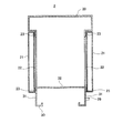
ここで、図2は、図1で示した、本実施形態のエンジン作業機の長手方向に直交したA−A断面を簡略化して示した図である。ただし、エンジンなどの内部機器は省略している。床台10は、図2に示すように下方が空けられた箱形をしたものであり、上部の床面11がフラットで水平な面が形成されている。そして、その床面10の長手方向側面12はパッケージ20よりも幅が狭く形成され、その下端からは水平に突き出した張出し部13が形成されている。パッケージ20は、その床台10を平面視した場合の外形形状に合った縦横の大きさで形成され、高さは搭載されるエンジンやオルタネータ或いはマフラーなどの配置に必要な大きさで形成されている。
Here, FIG. 2 is a simplified view of the AA cross section orthogonal to the longitudinal direction of the engine working machine of the present embodiment shown in FIG. However, internal devices such as engines are omitted. As shown in FIG. 2, the
パッケージ20の一部をなす開閉ドア21は、その表面がパッケージ20の外形形状を構成し、側面とほぼ面一になるように形成されている。開閉ドア21は、図10に示す開閉ドア220と同様に周縁部分が内側に折り返され立体的な形状をしており、不図示の防音材が貼り付けられている。開閉ドア21は、パッケージ20側面の開口部22を塞ぐように設けられ、本実施形態では、開閉ドア21の上辺部分が開口部22の上に当たり、その底辺部分は床台10の側面12に当てられるようになっている。そして、開閉ドア21の内側面が当たるパッケージ20および床台10には、いずれもゴム材23が貼設されている。なお、ゴム材23は、開閉ドア21の内側面に貼設するようにしてもよい。
従って、開閉ドア21がこのゴム材23に押し当てられてパッケージ20内を気密にする。一方で、その開閉ドア21には、底辺の内側に折り曲げられた折り曲げ部分24に排水穴25が数カ所あけられ、パッケージ20内の水がこの排水穴25から流れ落ちるようになっている。
The open /
Accordingly, the open /
以上のような構成からなる本実施形態のエンジン作業機1では、洗浄を行う場合、図3に示すように両側の開閉ドア21を開け、一方の開口部22からホース300で水を流すことによってパッケージ20内のゴミや埃を洗い流す。このとき、床台10の上部床面11がフラットであり、且つ開閉ドア21の底辺部分を床台10の側面に当てるようにしたので、水の流れを妨げる戸当りも無いことから、パッケージ20内のゴミや埃は水に洗い流されて反対の開口部22から流れ出る。こうして洗浄のために流した水がフラットな床台10の床面11をスムーズに流れ出るため、パッケージ20内に流れ出なかったゴミや埃そして水などが溜まることがなくなり、洗浄効果が上がった。
なお、図3では図の左側から水を流し込んでいるが、両側面ともにドアの戸当りがないことから、図の右側から流し込んでもよい。
In the
In FIG. 3, water is poured from the left side of the drawing, but both sides may be poured from the right side of the drawing because there is no door stop.
エンジン作業機1は、通常は野外に置かれたままになるためパッケージ20内には雨水などが入ったまま溜まってしまう。しかし、本実施形態のエンジン作業機1では、そうした水は開閉ドア21底辺の折り曲げ部分24に流れ込み、そこに形成された床面11より低い排水穴25から落ちて外へ出る。
また、運転中に侵入した水も同じように排水穴25から落ちるが、発電機を有するものの場合、運転中にパッケージ20内が負圧になることから、排水穴25から空気が吸い込まれる。この点、図14に示す水抜き穴136の場合、吸い込まれた空気によって、その周りの水がパッケージ内に飛散して内部を汚してしまう。しかし、本実施形態のエンジン作業機1では、排水穴25が狭い空間を構成する開閉ドア21底辺の折り曲げ部分24であって、床面11より低い位置に形成されているため、飛散した水はその折り曲げ部分24に留まって内部を汚してしまうことはない。
Since the
Further, water that has entered during operation also falls from the
また、本実施形態のエンジン作業機1は、エンジンなどを搭載する床台10が内部に広い空間を有する箱形をしたものである。従って、この床下空間に燃料タンクやマフラー等を配置させることができるようになった。これまで燃料タンクは図11に示すように、パッケージ内にて長手方向の一方に偏って配置されていた。そのため、図12に示す吊上金具122にクレーン車からのフックを引っかけてエンジン作業機100を吊り上げる場合、燃料タンク内の燃料が変わると重心がずれてしまってエンジン作業機が傾いてしまうことがあった。しかし、本実施形態では、床下に燃料タンクを入れることで全体の中央に配置させることができ、燃料の増減によって重心がほとんど変化しないようにすることができる。一方、床下にマフラーを入れる場合には、外部への排気口までの距離を長く取ることによってエンジン音を減衰させて騒音を抑えることができる。
Moreover, the
更に、床台10の長手方向側面12が開閉ドア21の表面よりも内側に位置している。そのため、図2に示すように、ドレン接続口29などを床台10の側面12から突き出るように取り付けても、エンジン作業機1全体でみた場合にはパッケージ20の側面より内側に位置しているので、ドレン接続口29などに何かをぶつけて破損させてしまうようなことを回避できる。
また、床台10には下端の張出し部13があるため、エンジン作業機1を現場で固定する必要がある場合には、その張出し部13を通してアンカーボルトを打ちつけることができ、設置が容易である。
Furthermore, the
Further, since the floor stand 10 there is
次に、本発明に係るエンジン作業機の他の実施形態について図4乃至図8を示して説明する。これらは、図2と同様、エンジン作業機の長手方向に直交した断面を簡略化して示した図であり、エンジンなどの内部構造は省略している。前記第1実施形態のエンジン作業機1と同様の構成については同じ符号を付して説明する。
先ず、図4は第2実施形態のエンジン作業機2を示した図である。これは、アンカーボルトによって固定が必要ないタイプのものである。一方、ドレン接続口29などの突き出した取付けが必要であるため、床台30の幅方向の寸法は側面31が開閉ドア21の表面よりも内側に位置するようになっており、固定のため底部が外側に張り出すことはなく内側に巻き込むように折り曲げられている。
Next, another embodiment of the engine working machine according to the present invention will be described with reference to FIGS. These are the figures which simplified and showed the cross section orthogonal to the longitudinal direction of an engine working machine like FIG. 2, The internal structures, such as an engine, are abbreviate | omitted. The same components as those of the
First, FIG. 4 is a view showing an
また、図5に示す第3実施形態のエンジン作業機3は、アンカーボルトによる固定の必要がないものであり、更にドレン接続口などの突き出しも無いタイプのものである。そのため、床台側面を凹ませた第1、第2実施形態のものとは異なり、床台40に段差41を形成し、開閉ドア21の底辺部分が当接する部分は幅が狭められ、当接しない部分は閉じたときの開閉ドア21の表面位置と同じ位置になるように幅が大きくなっている。
Further, the
第2、第3実施形態とも床台30,40の床面32,42を水平なフラットな面とし、その床面32,42より下に開閉ドア21の下端が位置するようにしたので、洗浄時の水はパッケージ20内のゴミや埃を洗い流してスムーズに流れ出るため、パッケージ20内に流れ出なかったゴミや埃そして水などが溜まることがなくなり、洗浄効果が上がった。
また、この他にも第1実施形態と同様に、運転時にパッケージ20内に入った水の飛散防止や、床台内の空間への燃料タンクなどの配置といった効果が得られる。
In both the second and third embodiments, the floor surfaces 32 and 42 of the floor bases 30 and 40 are horizontal flat surfaces, and the lower end of the open /
In addition, as in the first embodiment, effects such as prevention of scattering of water that has entered the
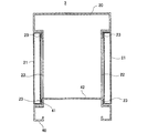
次に、図6に示した第4実施形態のエンジン作業機4は、アンカーボルトによって固定が必要ないのに加え、ドレン接続口などの突き出しが無いタイプのものであって、その床台50は、ベース部51上にエンジンなどを直接設置する設置部52が重ねられて二段になったものである。ベース部51は、前述した各実施形態の床台に比べて背の低いものであって、その上には箱形に形成されたフラットな床面53を構成する設置部52が固定されている。そして、開閉ドア21の底辺部分は、床面53よりも低い位置で設置部52の側面に当接するようになっている。
Next, the engine work machine 4 of the fourth embodiment shown in FIG. 6 is of a type that does not need to be fixed with anchor bolts, and that does not protrude such as a drain connection port. The
同じように、図7に示した第5実施形態のエンジン作業機5では、従来のように断面がコの字形のフレームからなるベース部61と、その上に箱形に形成され、エンジンなどを直接設置する設置部62が重ねて固定され、その設置部62にフラットな床面63が形成されている。そして、開閉ドア21の底辺部分は、床面63よりも低い位置で設置部62の側面に当接するようになっている。
更には、図8に示した第6実施形態のエンジン作業機6のように、従来のように断面がコの字形のフレームからなるベース部71と、その上にはエンジンなどを直接設置する板状の設置部72が重ねて固定され、フラットな床面73が形成されている。開閉ドア21の底辺部分がその板材の設置部72やベース部71を構成するコの字形をしたフレームの端部に当接するようになっている。
Similarly, in the
Further, as in the
こうした第4乃至第6実施形態のエンジン作業機4〜6でも、床台50,60,70はフラットな床面53,63,73を有し、その床面53,63,73より下に開閉ドア21の下端が位置するようにしたので、洗浄時の水はパッケージ20内のゴミや埃を洗い流してスムーズに流れ出るため、パッケージ20内に流れ出なかったゴミや埃そして水などが溜まることがなくなり、洗浄効果が上がった。
また、ベース部51,61,71の上にフラットな床面を有し、開閉ドアが側面に当接する設置部52,62,72を設けることにより、従来のベースフレームなどをそのまま利用して洗浄効果の高いエンジン作業機を提供することができる。
また、この他にも第1実施形態と同様に、運転時にパッケージ20内に入った水の飛散防止などの効果が得られる。
Also in the engine working machines 4 to 6 of the fourth to sixth embodiments, the floor bases 50, 60, and 70 have flat floor surfaces 53, 63, and 73, and are opened and closed below the floor surfaces 53, 63, and 73. Since the lower end of the
In addition, a flat floor surface is provided on the
In addition, as in the first embodiment, effects such as prevention of scattering of water that has entered the
以上、本発明のエンジン作業機について数種類の実施形態を説明したが、本発明はこれに限定されることなく、その趣旨を逸脱しない範囲で様々な変更が可能である。
例えば、前記各実施形態のエンジン作業機では床面を水平な面としたが、対峙して設けられた開口部22,22の一方側から他方側へわずかに傾斜させたり、その間の中央部分を高くして山形などするのが望ましい。このようにすれば、水洗いに使用した水が開口部22から外へ流れ易くなる。
また、例えば、エンジン作業機には、発電機を構成するものの他、オルタネータの変わりに油圧ポンプを搭載した油圧ユニットを構成するものであってもよい。
また、前記実施形態では、開閉ドア21底辺の折り曲げ部分24は、内側に折り返しを形成しているが、そうした返しを無くしたものであってもよい。
As mentioned above, although several types of embodiment was described about the engine working machine of this invention, this invention is not limited to this, A various change is possible in the range which does not deviate from the meaning.
For example, in the engine working machine of each of the embodiments described above, the floor surface is a horizontal surface. However, the opening
Further, for example, the engine working machine may constitute a hydraulic unit equipped with a hydraulic pump in place of the alternator in addition to the generator.
Moreover, in the said embodiment, although the
1 エンジン作業機
10 床台
11 床面
20 パッケージ
21 開閉ドア
22 開口部
23 ゴム
DESCRIPTION OF
Claims (4)
エンジンなどが設置される前記床台の床面がフラットな水平面、又は傾斜面であり、前記パッケージに形成された開閉ドアは、その底辺が床台の床面よりも低く、その内側底辺部分が床台側面に当接するようにしたものであり、
前記床台は、前記フラットな床面の下に燃料タンクなどの配置が可能な空間を有する箱形形状をしたものであり、且つ前記開閉ドアの当接する側面がその開閉ドア表面よりも内側に位置するものであり、
前記床台の側面に接続されたドレン接続口は、その先端が前記開閉ドア表面よりも内側に位置するものであることを特徴とするエンジン作業機。 In an engine working machine in which an engine, an alternator, a hydraulic unit, etc. are installed on a floor and surrounded by a package that forms a housing,
The floor surface of the floor base on which the engine or the like is installed is a flat horizontal surface or an inclined surface, and the open / close door formed in the package has a bottom lower than the floor surface of the floor base, and an inner bottom portion thereof all SANYO which is adapted to abut against the floor pad side,
The floor pedestal has a box shape having a space in which a fuel tank or the like can be arranged below the flat floor surface, and a side surface of the opening / closing door that contacts is inside the opening / closing door surface. Is located,
The drainage connection port connected to the side surface of the floor base has an end positioned on the inner side of the surface of the opening / closing door .
前記開閉ドアは、底辺部分には内側に折り曲げた折り曲げ部分を有し、前記床台の床面より低い位置に複数の排水穴があけられたものであることを特徴とするエンジン作業機。 In the engine working machine according to claim 1,
The engine work machine according to claim 1, wherein the open / close door has a bent portion bent inward at a bottom portion, and a plurality of drain holes are formed at a position lower than a floor surface of the floor base.
前記床台の下端には、外側に突き出した張出し部が形成されたものであることを特徴とするエンジン作業機。 In the engine work machine according to claim 1 or claim 2 ,
An engine working machine characterized in that a protruding portion protruding outward is formed at a lower end of the floor base.
前記床台は、ベース部の上にエンジンなどが直接設置される設置部が重ねられたものであり、その設置部は、床面がフラットであり、前記開閉ドアの底辺がその床面よりも低く、前記開閉ドアの内側底辺部分が側面に当接するようにしたものであることを特徴とするエンジン作業機。 The engine work machine according to any one of claims 1 to 3 ,
The floor pedestal is an installation part on which an engine or the like is directly installed on a base part. The installation part has a flat floor surface, and the bottom of the open / close door is more than the floor surface. An engine work machine characterized by being low and configured such that an inner bottom side portion of the open / close door is in contact with a side surface.
Priority Applications (1)
| Application Number | Priority Date | Filing Date | Title |
|---|---|---|---|
| JP2005009105A JP4958397B2 (en) | 2005-01-17 | 2005-01-17 | Engine working machine |
Applications Claiming Priority (1)
| Application Number | Priority Date | Filing Date | Title |
|---|---|---|---|
| JP2005009105A JP4958397B2 (en) | 2005-01-17 | 2005-01-17 | Engine working machine |
Publications (2)
| Publication Number | Publication Date |
|---|---|
| JP2006194219A JP2006194219A (en) | 2006-07-27 |
| JP4958397B2 true JP4958397B2 (en) | 2012-06-20 |
Family
ID=36800487
Family Applications (1)
| Application Number | Title | Priority Date | Filing Date |
|---|---|---|---|
| JP2005009105A Expired - Fee Related JP4958397B2 (en) | 2005-01-17 | 2005-01-17 | Engine working machine |
Country Status (1)
| Country | Link |
|---|---|
| JP (1) | JP4958397B2 (en) |
Family Cites Families (1)
| Publication number | Priority date | Publication date | Assignee | Title |
|---|---|---|---|---|
| JPS6127929U (en) * | 1984-07-25 | 1986-02-19 | 本田技研工業株式会社 | engine working machine |
-
2005
- 2005-01-17 JP JP2005009105A patent/JP4958397B2/en not_active Expired - Fee Related
Also Published As
| Publication number | Publication date |
|---|---|
| JP2006194219A (en) | 2006-07-27 |
Similar Documents
| Publication | Publication Date | Title |
|---|---|---|
| KR100894950B1 (en) | Cooling apparatus of construction machine | |
| JP6018426B2 (en) | Engine driven work machine | |
| JP2005229740A (en) | Electrical connection box for automobile | |
| JP6229694B2 (en) | Construction machine with engine | |
| JP4881224B2 (en) | Engine driven work machine | |
| JP4958397B2 (en) | Engine working machine | |
| JP7260311B2 (en) | construction machinery | |
| JP5575584B2 (en) | Engine working machine | |
| JP2013256904A (en) | Engine working machine | |
| JP2009138950A (en) | Air conditioner outdoor unit | |
| KR20110126521A (en) | Engine, and engine assembly | |
| JP4832106B2 (en) | Air conditioner for vehicles | |
| JP4235011B2 (en) | Engine intake piping structure | |
| JP5203720B2 (en) | pedestal | |
| JP5911709B2 (en) | Waterproof pan for washing machine | |
| JP2007056760A (en) | Rainwater intrusion prevention structure of stationary type engine working machine | |
| JP7515990B2 (en) | Rainwater drainage structure for engine-driven work equipment | |
| JP5462690B2 (en) | Engine working machine | |
| JP4587253B2 (en) | Rear exterior structure of construction machinery | |
| JP4472447B2 (en) | Sub-cleaner integrated engine cover | |
| KR101163690B1 (en) | Cylinder head cover assembly for engine | |
| JP6338609B2 (en) | Engine-driven work machine with leaked substance storage tank | |
| JP5089724B2 (en) | Exhaust port structure of engine driven work machine | |
| JP7635020B2 (en) | Soundproof box for engine-driven work equipment | |
| JPH08121162A (en) | Exhaust muffler for working machine |
Legal Events
| Date | Code | Title | Description |
|---|---|---|---|
| A621 | Written request for application examination |
Free format text: JAPANESE INTERMEDIATE CODE: A621 Effective date: 20071217 |
|
| A131 | Notification of reasons for refusal |
Free format text: JAPANESE INTERMEDIATE CODE: A131 Effective date: 20100713 |
|
| A521 | Request for written amendment filed |
Free format text: JAPANESE INTERMEDIATE CODE: A523 Effective date: 20100902 |
|
| A02 | Decision of refusal |
Free format text: JAPANESE INTERMEDIATE CODE: A02 Effective date: 20100928 |
|
| A521 | Request for written amendment filed |
Free format text: JAPANESE INTERMEDIATE CODE: A523 Effective date: 20120208 |
|
| A01 | Written decision to grant a patent or to grant a registration (utility model) |
Free format text: JAPANESE INTERMEDIATE CODE: A01 |
|
| A61 | First payment of annual fees (during grant procedure) |
Free format text: JAPANESE INTERMEDIATE CODE: A61 Effective date: 20120319 |
|
| FPAY | Renewal fee payment (event date is renewal date of database) |
Free format text: PAYMENT UNTIL: 20150330 Year of fee payment: 3 |
|
| R150 | Certificate of patent or registration of utility model |
Ref document number: 4958397 Country of ref document: JP Free format text: JAPANESE INTERMEDIATE CODE: R150 Free format text: JAPANESE INTERMEDIATE CODE: R150 |
|
| R250 | Receipt of annual fees |
Free format text: JAPANESE INTERMEDIATE CODE: R250 |
|
| R250 | Receipt of annual fees |
Free format text: JAPANESE INTERMEDIATE CODE: R250 |
|
| R250 | Receipt of annual fees |
Free format text: JAPANESE INTERMEDIATE CODE: R250 |
|
| R250 | Receipt of annual fees |
Free format text: JAPANESE INTERMEDIATE CODE: R250 |
|
| R250 | Receipt of annual fees |
Free format text: JAPANESE INTERMEDIATE CODE: R250 |
|
| R250 | Receipt of annual fees |
Free format text: JAPANESE INTERMEDIATE CODE: R250 |
|
| R250 | Receipt of annual fees |
Free format text: JAPANESE INTERMEDIATE CODE: R250 |
|
| LAPS | Cancellation because of no payment of annual fees |